

Page 1

Operator’s Manual
Page 2

NOTICE
The information in this document is subject to change without notice.
Welch Allyn makes no warranty of any kind on this material, including but not limited to, the implied
warranties of merchantability and fitness for a particular purpose. Welch Allyn shall not be liable for
errors contained herein or for incidental or consequential damages concerning the furnishing,
performance, or use of this material.
This document contains proprietary information that is protected by copyright. All rights are reserved. No
part of this document may be photocopied, reproduced or translated to another language without prior
written consent of Welch Allyn.
Before using this instrument, read this guide and become thoroughly familiar with the contents.
Welch Allyn only considers itself responsible for any effects on safety, reliability and performance of the
equipment if:
1 assembly operations, extensions, re-adjustments, modifications or repairs are done by persons
authorized by Welch Allyn, and
2 the electrical installation of the relevant room complies with the IEC or national requirements, and
3 the instrument is used according to the instructions for use presented in this manual.
WARNING
Welch Allyn assumes no liability for failures resulting from RF interference between Welch Allyn
medical electronics and any radio frequency device at levels exceeding those established by applicable
standards.
The use of accessories other than those recommended by Welch Allyn may compromise product
performance.
United States Federal law restricts this device to sale by or on the order of a licensed health care
practitioner.
Welch Allyn
Nellcor Puritan Bennett™ is a registered trademark of Nellcor Puritan Bennett, Inc.
and Atlas™ are registered trademarks of Welch Allyn, Inc.
ii
Page 3

Table Of Contents
1 HOW THIS MANUAL WORKS......................................................................................................................1
1.1 A QUICK TOUR OF THE WELCH ALLYN ATLAS MONITOR...........................................................................2
2 MONITORING THE PATIENT...................................................................................................................... 4
2.1 MONITORING BLOOD PRESSURE .................................................................................................................6
2.1.1 MAP (Mean Arterial Pressure) .............................................................................................................8
2.1.2 Alternate BP Field Settings (only available if language setting configured to Chinese).....................10
2.2 MONITORING SPO2, PULSE RATE AND THE SPO2 WAVEFORM...................................................................12
2.3 MONITORING HEART RATE AND THE ECG WAVEFORM............................................................................ 15
2.4 MONITORING IMPEDANCE RESPIRATION (MODELS 622XX & 623XX) .......................................................19
2.5 MONITORING TEMPERATURE (MODELS 622XX & 623XX) ........................................................................21
2.6 MONITORING CO2, RESPIRATION RATE, AND THE ETCO
3 MANAGING THE ALARMS......................................................................................................................... 25
3.1 PATIENT ALARMS .....................................................................................................................................29
3.1.1 Factory Default Patient Alarm Settings...............................................................................................30
3.2 MEASUREMENT INVALID ALARMS ............................................................................................................31
3.3 INSTRUMENT PROBLEM ALARMS ..............................................................................................................32
3.4 BATTERY ALARMS (MODELS 622XX & 623XX)........................................................................................33
4 CAPTURING AND DISPLAYING TREND DATA.....................................................................................35
5 USING PRINT AND WAVEFORM FREEZE .............................................................................................37
5.1 THE PRINTER – LOADING PAPER AND TROUBLESHOOTING .......................................................................39
6 CONNECTING TO THE PATIENT ............................................................................................................. 41
6.1 CONNECTING THE NIBP CUFF .................................................................................................................. 43
6.2 CONNECTING THE SPO
FINGERCLIP SENSOR............................................................................................46
2
6.3 CONNECTING THE ECG ELECTRODES .......................................................................................................48
6.4 CONNECTING THE TEMPERATURE PROBE (MODELS 622XX & 623XX)......................................................52
6.5 CONNECTING THE END TIDAL CO
SAMPLE TUBE (MODEL 623XX) .........................................................53
2
7 USING THE MENUS......................................................................................................................................54
7.1 THE SET DATE AND TIME AND OTHER OPTIONS MENU ............................................................................54
7.2 THE ADVANCED CONFIGURATION MENU.................................................................................................. 56
7.2.1 Advanced Configuration Menu Settings..............................................................................................58
8 CLEANING AND MAINTAINING THE ATLAS MONITOR ..................................................................60
WAVEFORM (MODEL 623XX) .........................23
2
9 UNPACKING AND INSTALLING THE ATLAS MONITOR...................................................................62
10 APPENDIX A: TECHNICAL SPECIFICATIONS FOR THE ATLAS MONITOR ................................ 64
11 APPENDIX B: ELECTROMAGNETIC COMPATIBILITY (EMC) ........................................................ 72
12 APPENDIX C: CALIBRATION AND MAINTENANCE ...........................................................................73
13 APPENDIX D: ACCESSORIES FOR THE WELCH ALLYN ATLAS MONITOR................................ 74
14 APPENDIX E: TROUBLESHOOTING........................................................................................................ 77
15 INDEX ..............................................................................................................................................................92
iii
Page 4

Safety Information
The Welch Allyn Atlas Monitor is intended for use in a hospital or clinical environment. It should not
be used at home or in emergency transport vehicles. Monitor users should be skilled at the level of a
technician, nurse, doctor or medical specialist.
The function of the Welch Allyn Atlas Monitor is to register ECG, CO
Noninvasive Blood Pressure (Systolic, Diastolic, and Mean Arterial Pressure), Pulse Oximetry,
Respiration Rate and Temperature for adult and pediatric patients (over the age of 3 years), in all hospital
or clinic facilities.
To ensure patient electrical isolation, the Atlas Monitor should only be connected to other equipment
that provides patient electrical isolation. When connecting the Welch Allyn Atlas Monitor to any
instrument, verify proper operation before clinical use. Accessory equipment connected to the monitor’s
serial data interface must be certified according to IEC Standard 950 for data-processing equipment or
IEC Standard 60601-1 for electromedical equipment. All combinations of equipment must be in
compliance with IEC Standard 60601-1-1 systems requirements. Anyone who connects additional
equipment to the signal input / output port is configuring a medical system and is therefore responsible
that the system comply with the requirements of IEC Standard 60601-1-1. If in doubt, consult the Welch
Allyn Technical Service Department.
The Welch Allyn Atlas Monitor and its accessories should be tested by qualified service personnel at
regular intervals to verify proper operation, according to the procedures of the user’s institution. A
Service Manual is available from the manufacturer. Other important safety information is located
throughout this manual where appropriate.
concentration, Heart Rate,
2
iv
Page 5
Warnings, Cautions, and Notes
All operating personnel should be familiarized with the general safety information in this summary.
Specific warnings and cautions will also be found throughout the operator’s manual. Such specific
warnings and cautions may not appear here in this summary.
This device has been tested and certified by the Canadian Standards
Association International to comply with applicable U.S. and Canadian
C
US
medical safety standards.
Defibrillator-proof, Type CF Applied Part.
Attention! Consult the accompanying documentation.
Handle with care.
Storage temperature. Refer to technical specification for more details.
Lead Acid Battery. For disposal see the Maintenance section of this
manual.
Storage humidity. Refer to technical specification for more details.
Warning – Tells you about something that could hurt the patient or hurt the operator.
Caution – Tells you about something that could damage the monitor.
Note – Tells you other important information.
v
Page 6

Warnings
• The Welch Allyn Atlas Monitor is designed for use by medical clinicians. Although this manual may
illustrate medical monitoring techniques, this system should only be used by a trained clinician who
knows how to take and interpret a patient’s vital signs.
• Do not operate this product in the presence of flammable anesthetics. Explosion may result.
• WARNING – PACEMAKER PATIENTS. Rate meters may continue to count the pacemaker rate
during occurrences of cardiac arrest or some arrhythmias. Do not rely entirely upon rate meter
alarms. Keep pacemaker patients under close surveillance. See this manual for disclosure of the
pacemaker pulse rejection capability of this instrument.
• This device must be used in conjunction with clinical signs and symptoms. This device is only
intended to be an adjunct in patient assessment. Certain arrhythmias or pacemaker signals could
adversely affect heart rate indications or alarms.
• During defibrillation, keep the discharge paddles away from ECG and other electrodes, as well as
other conductive components in contact with the patient. Avoid contact with any accessories
connected to the Welch Allyn Atlas Monitor’s panel.
• If pulse oximetry measurements are suspect, verify the reading using another clinically accepted
measurement method.
• Prolonged use or the patient’s condition may require changing the SpO
Change sensor site and check skin integrity, circulatory status, and correct alignment at least every 4
hours.
• When monitoring blood pressure over an extended period of time, or at frequent intervals, it is
recommended to check the cuff site and cuffed extremity regularly for possible ischemia, purpura
and/or neuropathy.
• Thoracic impedance respiration measurement may interfere with some pacemakers. Refer to the
pacemaker’s manual.
• To ensure patient safety, the conductive parts of the ECG electrodes (including associated
connectors) and other patient-applied parts, should not contact other conductive parts, including
earth ground, at any time.
• The safety and effectiveness of this product in the detection of apnea, particularly for infants and
neonates, has not been established.
• This equipment must not be connected to any other equipment that is not compliant with EN60601-1,
or a possibility exists that combined leakage currents could exceed safe limits.
• Do not fit the Blood Pressure or ETCO
systems with Luer Lock adapters. There is a risk of a user
2
mis-connection with an IV line introducing air bubbles into a patient’s blood.
• WARNING: Use of accessories, transducers, and cables other than those specified may result in
degraded electromagnetic compatibility performance of this device.
• Do not operate this product with MRI (Magnetic Resonance Imaging) equipment.
• It is the operator’s responsibility to set alarm limits as appropriate for each individual patient.
• Any Atlas Monitor which has been dropped or damaged should be checked by qualified service
personnel to insure proper operation prior to use.
• There are no user serviceable parts inside the Atlas Monitor other than paper replacement and
battery replacement.
• Blood pressure measurements may not be accurate for patients experiencing moderate to severe
arrhythmias.
• This Atlas Monitor should not be used on patients who are linked to heart / lung machines.
• If the integrity of the external protective conductor in the installation or its arrangements is in doubt,
equipment shall be operated from its internal power source (models 622xx and 623xx).
sensor site periodically.
2
vi
Page 7

• If an electrosurgical unit is used, place the ECG cable and wires as far as possible from the site of
the surgery and from the electrosurgical cables. This will minimize interference and the risk of burns
to the patient. Ensure that the electrosurgical return cable (neutral) is well attached and making good
contact with the patient.
• End tidal carbon dioxide (ETCO
ONLY when the second trace option is set to CO
ETCO
or ECG) the CO
and breath rate waveforms and data to another second trace selection (SpO2, Respiration
2
and breath rate monitoring and alarm capability will be disabled. This occurs
2
) and breath rate measurement and alarm capability are active
2
. Should the operator change from viewing the
2
even if the watertrap and cannula are still inserted into the Monitor.
• Impedance Respiration rate measurement and alarm capability are active ONLY when the second
trace option is set to Respiration. Should the operator change from viewing the Respiration
waveforms and breath rate to another selection (SpO
, CO2 or ECG) the Respiration rate
2
monitoring and alarm capability will be disabled. This occurs even if the ECG cable is still inserted
into the Monitor.
• If you are using battery power, the AC indicator (AC~) on the front panel will NOT be lit. When the
Atlas monitor is running on battery power, it will warn you when there is less than 10, less than 5,
and less than 1 minute of life remaining in the battery. See section 3.4 for battery alarm information.
• When using the motion tolerant pulse oximetry channel, a very sudden and substantial change in
pulse rate can result in erroneous pulse rate readings. Be sure to validate the patient data and patient
condition before intervention or change in patient care.
• When using the 6200-12 ECG Wrist-Klip, although a normal Lead I QRS waveform is produced on
the monitor, this waveform should not be used for serious clinical interpretation because the
electrodes are not properly triangulated around the patient’s heart.
• The 6200-12 ECG Wrist-Klip cannot be adjusted in size. Proper orientation of the clip with the
monitor depends on adjusting the position of the clip until a snug fit is found. The preferred position
of the clip is the patient’s wrist but it can be moved up the patient’s arm toward the torso. You may
find that the clip will not work with patients that have small wrists and arms. Caution must be
exercised when placing the clip so that circulation is not impeded along the patient’s wrist and arm.
If a snug fit cannot be found on the patient, other means of monitoring must be used.
Cautions
• When transporting or storing the Atlas monitor at temperatures between 40°C (104°F) and 50°C
°
F), the following procedure must be performed. The monitor must be returned to the normal
(122
°
operating temperature range of 10
patient monitoring is performed before two hours has elapsed, the displayed and printed ETCO2
values may be higher than the patient's actual values.
• Place the Welch Allyn Atlas Monitor and accessories in locations where they cannot harm the patient
if they fall off a shelf or mount.
• Never place fluids on top of this monitor. In case of fluid spilling on the monitor, disconnect power
cord, wipe clean immediately and have the monitor serviced to ensure that no hazard exists.
• This Welch Allyn Atlas Monitor should not be stacked directly on top of other equipment, and other
equipment should not be stacked on top of this Welch Allyn Atlas Monitor. If stacking is necessary,
observe the Welch Allyn Atlas Monitor to verify normal operation in the stacked configuration in
which it will be used.
• Unplug the external power cord from the monitor before cleaning or disinfecting the monitor.
• Do not autoclave, subject to ethylene oxide sterilization, or immerse the Welch Allyn Atlas Monitor in
liquid. Sterilize accessories only according to the manufacturer’s instructions.
C (50°F) - 40°C (104°F) for a period of at least two hours. If
vii
Page 8

• Make frequent electrical and visual checks on cables and electrode wires.
• Ensure the AC rating for the device is correct for the AC voltage at your installation site before using
the monitor. The AC rating is shown on the back of the instrument. If the rating is not correct, do not
use the monitor, and contact the Welch Allyn Technical Service Department for help.
• Line isolation monitor transients may resemble actual cardiac waveforms and thus inhibit heart rate
alarms. Use care in placement of ECG electrodes and routing of cables to avoid interference and
noise.
• Electrode polarization: the type of electrode used can affect the recovery time from overload,
especially defibrillation. Electrodes of dissimilar metals should not be used.
• If the accuracy of any measurement is in question, check the patient’s vital sign(s) by an alternate
method and then check the Atlas Monitor for proper functioning.
• Extremity and cuff motion should be minimized during blood pressure determinations.
• The pulse oximeter is calibrated to determine the percentage of arterial oxygen saturation of
functional hemoglobin. Significant levels of dysfunctional hemoglobins such as carboxyhemoglobin
or methemoglobin may affect the accuracy of the measurement.
• Grounding reliability can only be achieved when equipment is connected to an equivalent receptacle
marked “Hospital Only” or “Hospital Grade”.
Notes
• If the Atlas monitor is stored or transported at temperatures outside of the published storage
°
temperature range of -20
accuracy standards.
• Sidestream waste material and the CO
• Blood pressure measurements determined with this device are equivalent to those obtained by a
trained observer using the cuff/stethoscope auscultation method, within the limits prescribed by the
American National Standard, Electronic or automated sphygmomanometers (SP 10).
• Blood Pressure measurements can be affected by the position of the patient, by the patient’s
physiological condition, and other factors.
• The Blood Pressure system and Temperature system may not meet specifications if operated or stored
at conditions outside the stated ranges, or subjected to excessive shock or dropping.
• The Blood Pressure system is compliant with requirements of EN 1060-3:1995 Specification for
Noninvasive Sphygmomanometers.
• The Atlas Monitor is designed with protective circuitry and current isolation that eliminates any risk
to the patient from possible software errors.
C (-4°F) - 50°C (122°F) the Atlas monitor will not perform to the published
watertrap should be treated as biohazard material.
2
Product Warranty Information
Welch Allyn warrants the Welch Allyn Atlas Monitor, when new, to be free of defects in material and
workmanship and to perform in accordance with manufacturer’s specifications for a period of two years
from the date of purchase from Welch Allyn or its authorized distributors or agents. (Pulse oximetry
sensors and temperature probes are warranteed for one year). Welch Allyn will either repair or replace
any components found to be defective or at variance from the manufacturer’s specifications within this
time at no cost to the customer. It shall be the purchaser’s responsibility to return the instrument to Welch
viii
Page 9

Allyn or an authorized distributor, agent, or service representative. This warranty does not include
breakage or failure due to tampering, misuse, neglect, accidents, modification or shipping. This warranty
is also void if the instrument is not used in accordance with manufacturer’s recommendations or if
repaired by other than Welch Allyn or an authorized agent. Purchase date determines warranty
requirements. No other express warranty is given.
Return the Instrument Registration Card
Remember to submit the instrument registration card for warranty validation. Complete the information
and mail the pre-addressed card to Welch Allyn. You may also register on-line at
<http://www/welchallyn.com/medical/support/warranty
>.
Service Information: Service Policy
All service and repairs must be performed by authorized Welch Allyn personnel or agents, using
approved Welch Allyn replacement parts and approved process materials. Failure to do so will invalidate
the product warranty. Please refer to the product warranty for specific coverage.
Service Information: Technical Assistance
If you have an equipment problem that you cannot resolve, call the Welch Allyn Service Center nearest
you for assistance. Technical service support is available to you by telephone on normal business days at
the phone numbers listed below.
If you are advised to return a product to Welch Allyn for service or repair, schedule the repair with the
service center nearest you.
Before returning a product for repair you must obtain authorization from Welch Allyn. An RMA
(Return Materials Authorization) number will be given to you by our service personnel. Be sure to
note this number on the outside of your shipping box. Returns without an RMA number will not be
accepted.
ix
Page 10

Service Information
For Technical Support or to obtain return instructions, please contact your nearest Welch Allyn service
center:
USA 1-800-535-6663 France (+33) 1-60-09-33-66
Australia (+61) 2-9638-3000 Latin America (+1) 305-669-9591
Germany (+49) 7477-927-173 Singapore (+65) 6291-0882
Europe (+353) 469-067-790 Canada 1-800-561-8797
Japan (+81) 3-5212-7391 UK 0-207-365-6780
South Africa (+27) 11-777-7509 China (+86) 21-6327-9631
CLINICAL SUPPORT
For clinical questions about Atlas Monitor call the Welch Allyn Clinical Support line at 800-769-4014
Extension 3225 or 315-685-4100 Extension 3225.
x
Page 11

European contact for regulatory compliance:
European Regulator Manager
Welch Allyn LTD.
Navan, Co. Meath
Republic of Ireland
Phone 353-46-67700
Fax: 353-46-27128
Service Information: Service Manual / Spare Parts
A service manual is available by request to qualified electronics personnel. The service manual is a
comprehensive guide to troubleshooting, service and repair of the Welch Allyn Atlas Monitor.
A complete spare parts price list is available upon request. Spare parts may be ordered from your local
Welch Allyn Service Center.
Service Information: Service Loaners
Service loaners are provided, on request, when repair service is provided by a Welch Allyn Service
Center. Loaners for products repaired while under the original warranty, or while under extended
warranty or service contract, are provided free of charge and are shipped within 48 hours of notification
of need. Shipment charges to the user are paid by Welch Allyn.
For service repairs outside of warranty or contract, loaners will be available for a nominal charge and will
be shipped subject to availability. Loaners will be shipped pre-paid.
xi
Page 12

xii
Page 13

1 How This Manual Works
This manual is arranged so that everything about one topic is found in a single section. The statement
immediately below the chapter title (like this one) appears in italics and presents the important points of
the topic. Most topics include an illustration or a table. The chapters are numbered so that logically
connected topics begin with the same number-- for example 2.1 and 2.2.
The Welch Allyn Atlas Monitor and this manual
are designed for ease of use. Everything you
need to know about a specific operation of the
monitor is available in one place. This means
you can see all the required information at a
glance.
Redundancy - There is some redundancy in this
manual; some step-by-step procedures are
repeated in many places wherever they are
pertinent. We did this so you would not have to
search through other pages to find what you
need to know “right now.”
For instance, setting an alarm limit is fully
explained in the section on blood pressure, again
in the section on SpO
places.
Paragraphs - The statement in italics
immediately below the chapter heading
describes what the section is about. Sometimes
just reading this and looking at the illustrations
, and in several other
2
will give you enough information.
Section Numbers - The double numbered pages
indicate the relationship between the main
subject and closely related topics.
The sections are organized so that what you
want to know first is put first. Like most medical
professionals who use the Atlas Monitor, you
are probably very adept at taking blood pressure
and connecting ECG leads to patients, so the
section on how the Atlas Monitor is used for
monitoring patients and what you need to know
to operate the monitor comes first. We put the
information on connecting blood pressure cuffs
and ECG leads in a later section.
This manual is not meant for reading straight
through, like a book, although you can read it
that way. If you read it like this, the built-in
redundancy may become a little tedious. When
you read a paragraph or a step-by-step procedure
with which you are already familiar, just skip it.
It is there for the person who is doing the
activity for the first time.
1
Page 14

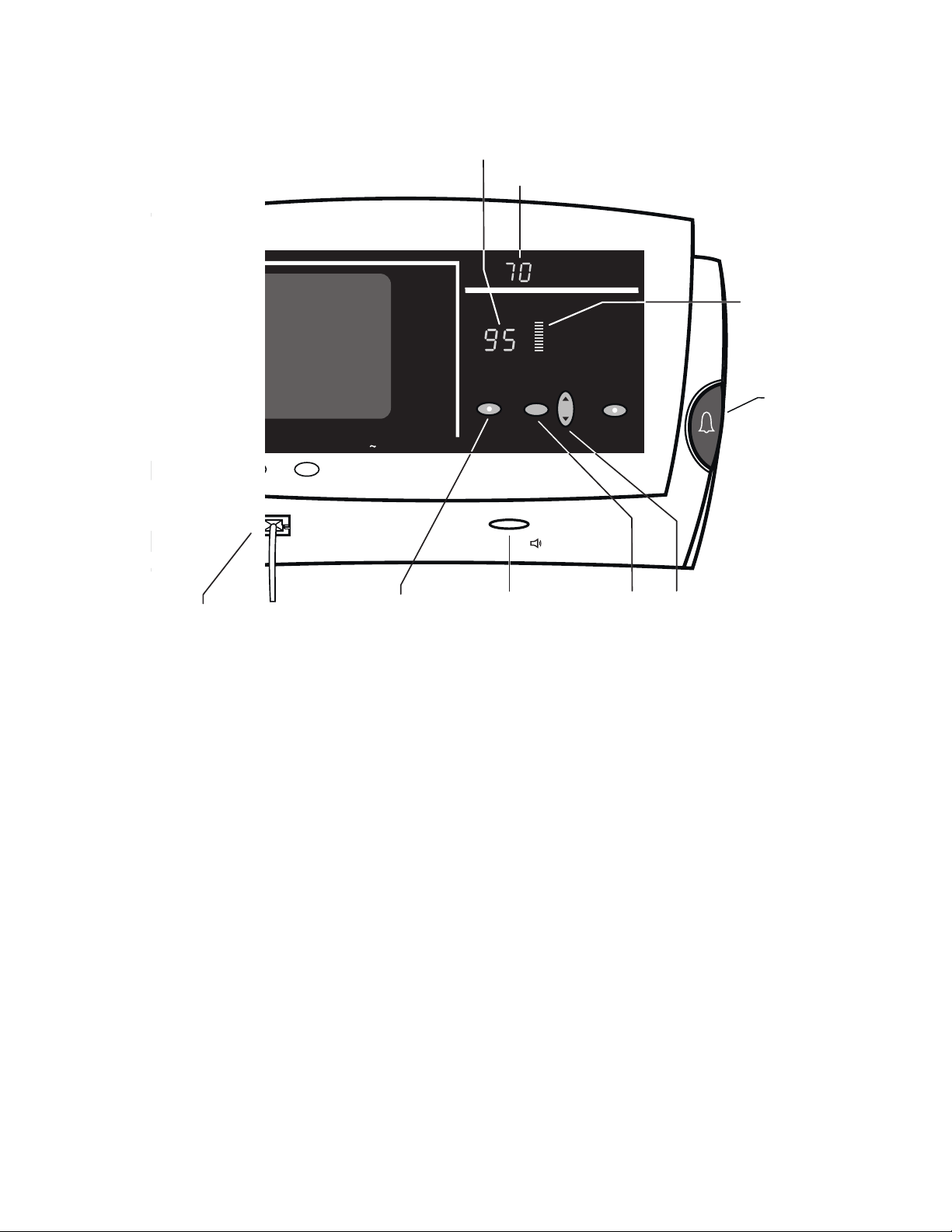
1.1 A Quick Tour of the Welch Allyn Atlas Monitor
When you turn on the power, the monitor starts with preset or default alarm levels. Waveforms are
displayed on the screen. Readings are displayed on the screen and on LEDs. You can perform the most
common operations — set and silence alarms, display trend data, print waveforms and trend data — from
the front panel without using a menu. This section gives only a brief overview of the monitor; later
sections present all the details.
Which model do you have? The Welch Allyn
Atlas Monitor is a single, portable unit providing
all the measurement capability normally needed to
monitor patients under anesthesia, patients
recovering from surgery, and patients who require
bedside monitoring. The model number is
encoded into the first three digits of the serial
number on the back of the unit. There are three
models:
Model
621NO
621NP
Features
SpO2, SpO2 waveform
Pulse Rate
NIBP: Systolic, Diastolic, MAP
ECG waveform, heart rate
Printer (optional)
622NO
622NP
All features of model 621xx,
plus:
Impedance Respiration
Patient Temperature
Battery Operation
PC Communication
Remote Nurse Call
Printer (optional)
623NP All features of model 622xx,
plus:
End Tidal CO
from ETCO
and Breath Rate
2
2
Printer (standard)
Power on - The Power On/Standby button is in
the lower right corner. When you first turn on the
monitor:
• all alarms are enabled, but no alarm will
sound until after a valid measurement value is
received.
• all alarm limits are set at their default values.
• all the trend data (history) is cleared.
2
AC~ indicator, located below the screen,
A lit
means the unit is being powered by the wall
outlet, and that the battery is being charged
(models 622xx and 623xx).
NOTE: Use the battery as a backup for low
power conditions or short-term transports.
Silencing Alarms - You can silence any alarm for
90 seconds by pressing the large blue
Silence
button on the right-hand edge of the instrument.
Silenced alarms continue to flash, as long as the
measurement is outside the alarm limits. When
alarms are silenced, they will not trigger a Print
On Alarm. When the silence period is over, an
alarm that is still active will trigger a Print On
Alarm if the Print On Alarm configuration is set
to Yes.
You can suspend an individual alarm by pressing
ALARMS Off button. There are four ALARMS
its
Off
buttons, each controlling a different group of
measurements. The audible alarm is suspended as
long as the red LED in the button is lit. When an
alarm is suspended, the audible alarm will not
sound, but readings will still flash when the
measurement is outside the limits. When an alarm
is suspended, it will not trigger a Print On Alarm.
When the alarm is unsuspended, an alarm that is
still active will trigger a Print On Alarm if the
Print On Alarm configuration is set to Yes.
Note: Individual alarms can be suspended for only
3 minutes when the language setting is
configured to “Francais”. If the language is set
to any other language, pressing the individual
ALARMS Off buttons will suspend the alarm
until you remove the suspension.
Page 15

Trend Data - Trend data is captured every time
blood pressure is measured, whether this event is
automatic or manual. Trend data is also
automatically captured every 15 minutes if blood
pressure intervals are longer, or blood pressure is
not used. Push the
data. Scroll through the trend data with either
button. Push
Trend button to see the trend
Set
Trend again to return to the
waveform display. The monitor will hold up to
144 lines of trend data, which is 36 hours if data is
captured every 15 minutes.
Printing - A printer option is available with both
models 621xx and 622xx, and is a standard model
623xx feature. Push the
Print button to print what
is on the screen. If the waveforms are displayed
on the screen, the
Print button prints 15 seconds
of waveforms plus all the current measurements.
The printout captures data from 9 seconds before
Print button was pressed until 6 seconds after.
the
Note: If any measurements exceed the alarm
limits, they will be marked with asterisks on
the printout. If trend data is displayed on the
screen,
Print prints all the trend data. If the
Print On Alarm configuration is set to Yes, and
a Patient Alarm or Measurement Invalid Alarm
occurs, Atlas will print the current
measurements and the currently configured
waveforms automatically.
If your model of the Atlas Monitor does not have
the optional printer, the
Freeze, and it freezes, or halts, the waveform
Print button is labeled
display for 10 seconds to permit studying of the
waveform.
3
Page 16

2 Monitoring the Patient
The patient’s vital measurements are displayed as numeric readings and as waveforms. You can set the
measurement limit alarm levels, silence the alarms for a short period, and suspend individual alarms.
You can print waveforms and current measurements, or print all the stored trend data.
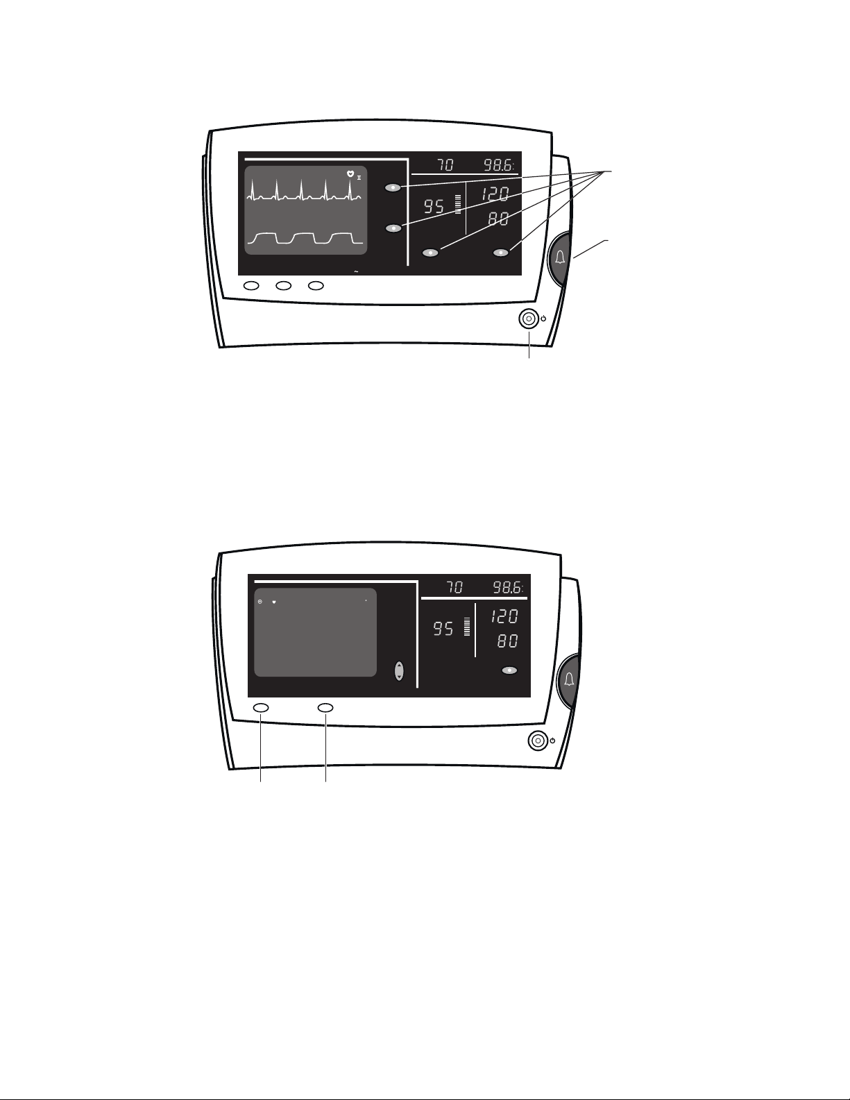
The front panel has two sides:
The left side displays
waveforms, numeric
readings, and trend
data on a CRT screen.
The right side has
measurements
displayed in green
and red LEDs.
Each side responds to the adjacent
Select and Set
buttons used for setting alarm limits. Each side
also has
ALARMS Off buttons, which are used to
suspend (turn off) individual alarms.
Note: Individual alarms can be suspended for only
3 minutes when the language setting is configured
to “Francais”. If the language is set to any other
language, pressing the individual
ALARMS Off
buttons will suspend the alarm until you remove
the suspension.
Note: The temperature measurement does not
have an alarm.
Setting alarm limits - Press the
Select button to
choose which alarm limit you want to set. Each
time you press the
next alarm, shown by small
Select button, it cycles to the
HI and LO indicators,
and the measurement display flashes the current
alarm setting. The
Set button changes this alarm
limit. Press the top or bottom of the button to
change the limit up or down.
Note: the flashing alarm-setting mode only lasts
10 seconds before reverting back to the normal
measurement mode. If you take too long to set
a limit, you’ll need to press the
Select button
and start over again.
Press the
Select button to go to the next
measurement alarm. Press it several times to cycle
out of all the alarm settings and go back to the
normal measurement mode.
Silencing alarms - The
Silence button silences
all alarms for 60, 90 or 120 seconds. This silence
period can be set to one of these three choices in
Advanced Configuration. During the silence
period, there will be no audible alarms, even for
measurements that go outside the limit range for
the first time. However, any measurement that is
outside the limits you set will flash. When alarms
are silenced, they will not trigger a Print On
Alarm. When the silence period is over, an alarm
that is still active will trigger a Print On Alarm if
the Print On Alarm configuration is set to Yes.
Trend data - Press the
Trend button to see the
trend data. The waveform display is replaced by
the first screen of trend data, starting with the
most recent measurements at the top. View the
rest of the trend data by pressing the
Set button up
or down.
The trend memory can hold up to 144 lines of
measurements, which is 36 hours of data if taken
at 15-minute intervals.
Printing - The
Print button prints what you see
on the screen - the waveforms (including all
current measurements) or the screen with trend
data. When you push the button, waveforms are
printed starting from 9 seconds before you pushed
Print button until 6 seconds after you pushed
the
the button for a total printout of 15 seconds. The
other information on the printout is captured at the
time that the
Print button is pressed. If the Print
On Alarm configuration is set to Yes and a Patient
Alarm or Measurement Invalid Alarm occurs,
Atlas will print the current measurements and the
currently configured waveforms automatically.
Freeze – If your monitor does not have a printer,
the button is labeled
Freeze. Pressing Freeze
stops the waveform display for 10 seconds, and
then the readout resumes.
4
Page 17
12
Trend
RR
Lead Select Print
70
23%
2
ALARMS
Off
TEMP
Systolic
HI
Diastolic
LO
(mmHg)
(mmHg)
BP ALARMS
F
C
HI
LO
HI
LO
Off
Alarm
Suspend
Buttons
Silence
PULSE
(bpm)
HR ALARMS
Off
SpO2%
2
/ RESP
CO
ALARMS
Off
SpO
AC
Power
TEMP
Systolic
Diastolic
LO
(mmHg)
(mmHg)
BP ALARMS
F
C
HI
LO
HI
LO
NIBP Sp0
2
CO2
3:50 70 122/89(--) 92 38 14/min 98.6
3:40 69 120/84(--) 95 38 12/min 95.4
3:30 70 119/88(--) 92 33 10/min 98.6
3:20 70 120/82(--) 95 36 12/min 96.2
3:10 74 128/86(--) 97 40 16/min 98.7
3:00 72 122/85(--) 90 38 12/min 95.6
2:50 70 120/86(--) 98 33 14/min 98.6
2:40 66 118/80(--) 95 38 10/min 98.6
2:30 67 120/78(--) 96 37 12/min 97.5
2:20 70 120/80(--) 95 38 12/min 98.6
2:10 68 121/85(--) 94 35 10/min 97.6
Trend
mmHg
Print
Trend Print
PULSE
(bpm)
RR
F
SpO2%
Set
Top – Model 623xx showing waveform display and alarm controls
Bottom – Model 623xx showing trend display and associated
controls
5
Page 18

2.1 Monitoring Blood Pressure
Blood pressure can be measured at timed intervals which you set, or you can start the blood pressure
measuring cycle manually. Systolic and Diastolic readings are shown on the LEDs at the upper right of
the monitor. You can set the high and low alarm limits for both the systolic and diastolic measurements.
Blood pressure cycles - You can measure NIBP
at timed intervals or manually. To set a timed
interval, press the
Auto button to cycle through
the available intervals: X, 1, 3, 5, 10, 15, 30, or
60 minutes. Wait until the number for the
selected interval stops flashing; the measurement
will automatically begin 20 seconds later.
Note: The interval is timed from the start of one
BP cycle to the start of the next cycle.
Pressing the button one more time after the 60 is
lit will return the
Auto timing to the Off mode
(indicated by an “X”). In this mode, automatic
measurement at timed intervals will not occur.
Initially, both blood pressure displays will be
blank.
Stopping a blood pressure cycle - The
Start/Cancel
button does one of two things:
BP
• If a blood pressure measurement is not in
progress, pressing
BP Start/Cancel will
start a blood pressure measurement cycle,
whether the
Auto timer is set to a specific
interval or is off.
• If a blood pressure measurement is in
progress, pressing BP Start/Cancel will
deflate the cuff immediately and cancel the
measurement. If the
Auto button is in one of
the timed modes, the cuff will inflate again
after the selected number of minutes.
Note: Canceling a blood pressure cycle does not
end automatic BP timing. If the
Auto is set to
any number, the next blood pressure cycle
will start again after that number of minutes
has elapsed.
Alarms - When any of the blood pressure limits
are exceeded, an audible alarm sounds and the
affected measurement flashes. If the Print On
Alarm configuration is set to Yes, a blood
pressure alarm will trigger an automatic print.
You can silence the blood pressure alarm, and
all alarms, by pressing the large blue
Silence
button at the right side of the instrument. This
will silence all alarms for 60, 90, or 120
seconds, depending on the setting selected in
Advanced Configuration. However, any
measurement still outside the set limits will
flash. When alarms are silenced, they do not
trigger a Print On Alarm.
To suspend the blood pressure alarms, press the
BP ALARMS Off button so the red LED in the
button lights. A suspended alarm will still flash
if it goes outside the range of the limits, but it
will not sound the audible alarm. When an alarm
is suspended, it will not trigger a Print On
Alarm.
Note: The blood pressure alarm can be
suspended for only 3 minutes when the
language setting is configured to “Francais”.
If the language is set to any other language,
pressing the
BP ALARMS Off button will
suspend the alarm until you remove the
suspension.
Trend data – Trend data is captured at each
blood pressure cycle, whether it is started
automatically or manually. If the
Auto timing of
NIBP is off (X), or greater than 15, then trend
data is captured every 15 minutes.
Initial pressure – The initial cuff pressure can
be set in the Advanced Configuration. The Atlas
Monitor will pump up to the selected initial cuff
pressure. If this pressure is too low to measure
the systolic pulse, the system will repeatedly
increase pressure by 40 mmHg and measure
again.
6
Page 19
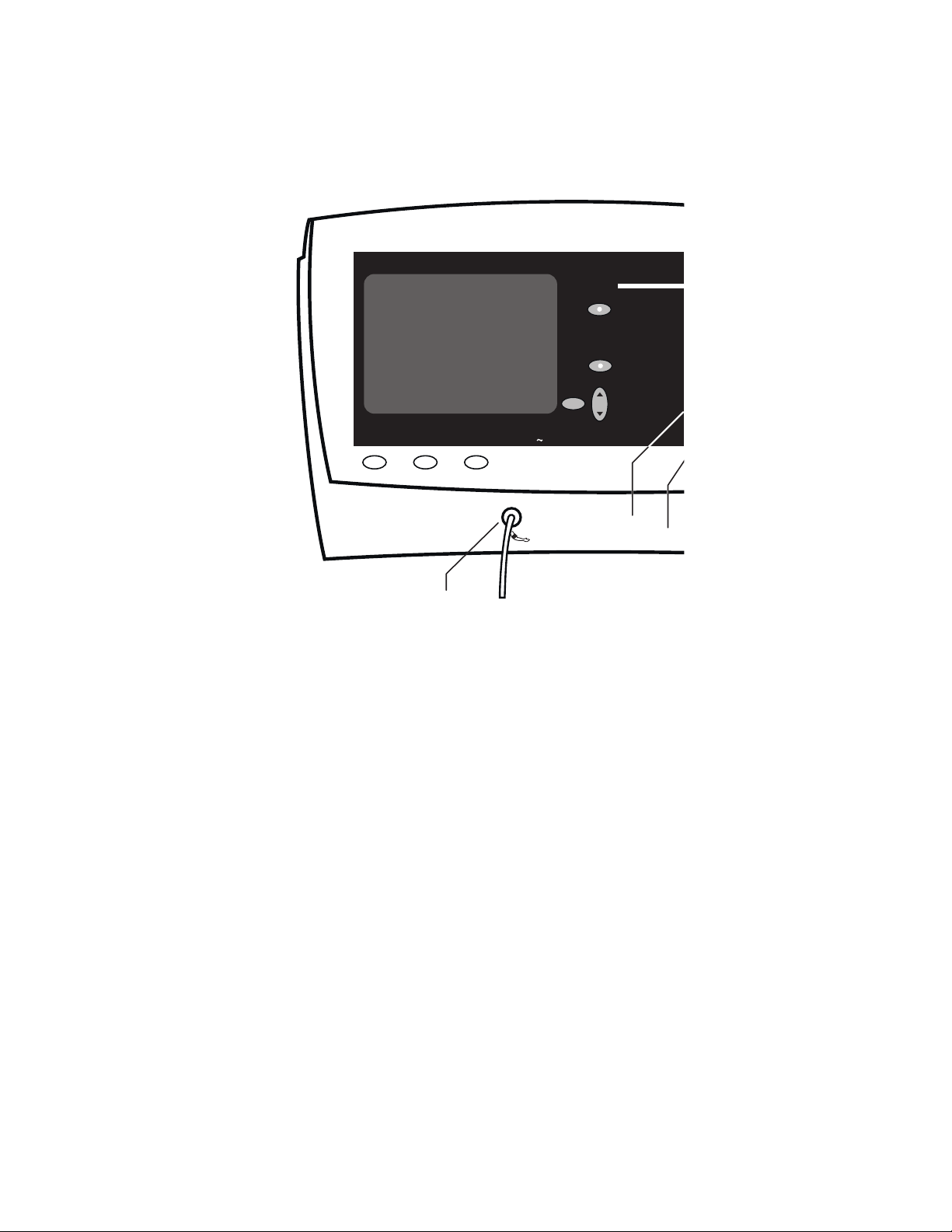
PG 2-5
Off
CO2 / RESP
ALARMS
Off
Select
Set
Lead Select Print
Trend
Blood
Pressure
Connector
Atlas Monitor showing NIBP displays, controls and tubing
connector
Setting alarm limits - To set the Systolic and
Diastolic alarm limits, use the
buttons on the right side of the monitor to follow
these steps:
• Press the
SpO
Diastolic
• Each push of
Select button to cycle through
LO, then Systolic HI and LO, and
2
HI and LO.
Select moves you to the next
limit. Stop at the limit you want to set. The
measurement and the
flash, indicating which limit is being
changed.
• Press the Set button up or down to raise or
lower the alarm limit. (When you come to
the end of the range, the numbers will stop
changing).
• Press the
Select button again to go to the
Select and Set
HI or LO LED will
AC
Select
Set
next limit, or press it several times until
none of the measurements flash and no
LO LEDs are lit. The instrument is now in
HI or
its normal measurement mode. (If you do
not press any button for 10 seconds, the
instrument will automatically revert to its
normal measurement mode).
Note: If the language setting is configured to
Chinese and the alternate BP field to kPa, the
blood pressure will be displayed in kPa on the
screen, but the Systolic and Diastolic readings
on the right side of the monitor will be displayed
in mmHg. When setting the alarm limits, the
and
LO alarm limits will be displayed in mmHg
on the right side of the monitor and in kPa on the
screen.
HI
7
Page 20

2.1.1 MAP (Mean Arterial Pressure)
Mean Arterial Pressure is calculated from the systolic and diastolic measurements. MAP may be
optionally displayed by selecting it on the Advanced Configuration menu. MAP is displayed in the upper
left corner of the screen.
MAP - (Mean Arterial Pressure) display can be
turned on and off by using the Advanced
Configuration menu. When MAP is shown, you
will see it in the upper left corner of the screen,
above the ECG waveform.
To display (or turn off) MAP, enter the Advanced
Configuration menu:
• Press the
• Press the
• Use the left
Date/Time button.
Trend button.
Select button to highlight
“MAP.”
• Press the left
• Press the
Set to choose “Yes” or “No.”
Trend button again to exit
Advanced Configuration.
If MAP is displayed on the screen, it will also
appear in the trend data and in the current
readings of a waveform printout.
Alarms - When either of the MAP limits are
exceeded, an audible alarm sounds and the
affected measurement flashes. If the Print On
Alarm configuration is set to Yes, a MAP alarm
will trigger an automatic print. You can silence
the MAP alarm, and all alarms, by pressing the
large blue
Silence button at the right side of the
instrument. This will silence all alarms for 60, 90,
or 120 seconds, depending on the setting selected
in Advanced Configuration. However, any
measurement still outside the set limits will flash.
When alarms are silenced, they do not trigger a
Print On Alarm.
To suspend the MAP alarm, press the
ALARMS Off
button so the red LED in the button
BP
lights. A suspended alarm will still flash if it goes
outside the range of the limits, but it will not
sound the audible alarm. When an alarm is
suspended, it will not trigger a Print On Alarm.
Note: The BP alarm can be suspended for only 3
minutes when the language setting is
configured to “Francais”. If the language is set
to any other language, pressing the
ALARMS Off
button will suspend the alarm
BP
until you remove the suspension.
Note: MAP is calculated mathematically from the
Systolic and Diastolic pressures; it is not
measured directly.
Setting alarm limits – If MAP is displayed, you
can set the alarm limits, using the
Select and Set
buttons on the left side of the monitor to follow
these steps:
• Press the left Select button to cycle
through MAP
LO, Respiration HI and LO (models 622xx
or 623xx)
LO.
HI and LO, Heart Rate HI and
, then (model 623xx) CO
HI and
2
• Each push of Select moves you to the next
limit. Stop at the limit you want to set. The
measurement and
HI or LO will flash,
indicating which limit is being changed.
• Press the Set button up or down to raise or
lower the alarm limit. (When you come to
the end of the range, the numbers will stop
changing).
• Press the Select button again to go to the
next limit, or press it several times until
none of the measurements flash and no
LO indicators are lit. The instrument is
or
HI
now in its normal measurement mode. (If
you do not press any button for 10 seconds,
the instrument will automatically revert to
its normal measurement mode).
8
Page 21
Map
MAP 96
Trend
Lead Select Print
Blood
Pressure
Connector
70
AC
Select
HR ALARMS
CO
2 / RESP
ALARMS
Off
Off
BP ALARMS
Set
SetSelect
Blood
Pressure
Alarm Off
Off
Atlas Monitor waveform display showing location of MAP reading
Silence
9
Page 22

2.1.2 Alternate BP Field Settings (only available if language setting
configured to Chinese)
Mean Arterial Pressure or blood pressure in kPa can be displayed by selecting it on the Advanced
Configuration menu. MAP or kPa is displayed in the upper left corner of the screen and is included on
the printout.
You can display MAP (Mean Arterial Pressure) or
blood pressure in kPa (kiloPascals) in the upper
left corner of the screen, above the ECG
waveform. This alternate BP field display can be
set by using the Advanced Configuration menu.
To set the alternate BP field display , enter the
Advanced Configuration menu:
• Press the
• Press the
• Use the left
Date/Time button.
Trend button.
Select button to highlight
“Alternate BP Field:”.
• Press the left
Set to choose “MAP”, “kPa”,
or “Nothing.”
• Press the
Trend button again to exit
Advanced Configuration.
MAP - If MAP is displayed on the screen, it will
also appear in the trend data and in the current
readings of a waveform printout.
MAP Alarms - When either of the MAP limits
are exceeded, an audible alarm sounds and the
affected measurement flashes. If the Print On
Alarm configuration is set to Yes, a MAP alarm
will trigger an automatic print. You can silence
the MAP alarm, and all alarms, by pressing the
large blue
Silence button at the right side of the
instrument. This will silence all alarms for 60, 90,
or 120 seconds, depending on the setting selected
in Advanced Configuration. However, any
measurement still outside the set limits will flash.
When alarms are silenced, they do not trigger a
Print On Alarm.
To suspend the MAP alarm, press the
BP
ALARMS Off
button so the red LED in the button
lights. A suspended alarm will still flash if it goes
outside the range of the limits, but it will not
sound the audible alarm. When an alarm is
suspended, it will not trigger a Print On Alarm.
Note: MAP is calculated mathematically from the
Systolic and Diastolic pressures; it is not
measured directly.
Setting alarm limits – If MAP is displayed, you
can set the alarm limits, using the
Select and Set
buttons on the left side of the monitor to follow
these steps:
• Press the left Select button to cycle
through MAP
LO, Respiration HI and LO (models 622xx
or 623xx)
LO.
HI and LO, Heart Rate HI and
, then (model 623xx) CO
HI and
2
• Each push of Select moves you to the next
limit. Stop at the limit you want to set. The
measurement and
HI or LO will flash,
indicating which limit is being changed.
• Press the Set button up or down to raise or
lower the alarm limit. (When you come to
the end of the range, the numbers will stop
changing).
• Press the Select button again to go to the
next limit, or press it several times until
none of the measurements flash and no
or
LO indicators are lit. The instrument is
HI
now in its normal measurement mode. (If
you do not press any button for 10 seconds,
the instrument will automatically revert to
its normal measurement mode).
10
Page 23

kPa – If the blood pressure is displayed in kPa on
the screen, the blood pressure readings will be in
kPa in the trend data and in the current readings of
the waveform printout.
Note: To set the blood pressure limits in kPa, you
will need to use the Select and Set buttons on
the right side of the monitor. The
alarm limits for systolic and diastolic will be
displayed in mmHg on the right side of the
monitor and in kPa on the screen.
HI and LO
11
Page 24

2.2 Monitoring SpO2, Pulse Rate and the SpO2 Waveform
The oximetry and pulse rate measurements are generally taken with the reusable fingerclip sensor
(provided), however a wide variety of SpO
volume is displayed as a vertical bar graph, called the Plethysmograph, beside the SpO
right side of the monitor. The SpO
pulse tone gives an audible indication of pulse rate and oxygen level.
2
Pulse - A fingerclip sensor provides the source
of the light transmitted through the patient’s
finger to determine the oximetry and pulse rate
measurements. The green Pulse Rate numbers
may sometimes differ slightly from the Heart
Rate displayed over the ECG waveform, even
though they both measure beats per minute
(bpm). This is normal.
Oxygen level - The oxygen level is displayed in
red numbers as a percentage. The
Plethysmograph vertical bar graph next to the
percentage shows the strength of the
SpO
2
fingerclip sensor signal with each beat. If this
signal is low, it could indicate that the fingerclip
sensor is not placed properly, or that the patient
has poor perfusion. Pigmented skin and nail
polish can also lower the signal.
System Displays – The system will begin
displaying the Plethysmograph signal almost
immediately upon attachment of the fingerclip
sensor to the patient. The SpO
level and Pulse
2
Rate will be displayed within about 5 seconds,
after the system determines that the reading is
stabilized.
Second waveform - The pulse oximetry
waveform can be selected as a second trace. If
this is chosen, the bottom line of the screen
displays the SpO
waveform. Select the Second
2
trace source from the Advanced Configuration
menu.
Pulse tone - A short SpO
tone sounds with
2
every pulse beat.
• The pulse tone timing is based on the ECG
heart rate. If ECG is not used, the pulse tone
timing is based on the SpO
measurement.
2
• The pulse tone pitch is determined by the
oxygen level, increasing in frequency (pitch)
sensors are available as accessory items. The oximetry pulse
2
% display on the
2
as the percentage of oxygen elevates.
The pulse tone volume can be controlled by a
button on the lower right panel. The button is
below the SpO
icon and
display, labeled with a speaker
2
SpO
.
2
Note: The pulse tone volume can be turned
completely off with this button.
Note: If the SpO
SpO
pulse tone is in synchrony with the
2
is inactive, the timing of the
2
ECG heart rate as is normally the case, but
the pitch of the tone is steady, unvarying, and
different from the tone tracking oxygen
content.
Alarms - When the oxygen percentage falls
below the SpO
limit, an alarm sounds and the
2
affected measurement flashes. If the Print On
Alarm configuration is set to Yes, an SpO
will trigger an automatic print. You can silence
the SpO
large blue
alarm, and all alarms, by pressing the
2
Silence button at the right side of the
instrument. This will silence all alarms for 60,
90, or 120 seconds, depending on the setting
selected in Advanced Configuration. However,
any measurement still outside the set limits will
flash. When alarms are silenced, they do not
trigger a Print On Alarm.
To suspend the SpO
ALARMS Off button so the red LED in the
alarm, press the SpO
2
button lights. A suspended alarm will still flash
if it goes outside the range of the limits, but it
will not sound the audible alarm. When an alarm
is suspended, it will not trigger a Print On
Alarm.
alarm
2
2
12
Page 25
e
Oximetry
Measurement
Pulse Rate
PULSE
(bpm)
Signal
Strength
Silenc
12/
min
SpO2%
SpO2ALARMS
Off
LO
Select
BP ALARMS
Off
Set
Trend
CO
SpO
2
Connector
Lead Select Print
2
2
SpO
AC
Alarms Off
SpO2
SpO
2
+
-
SpO
2
Pulse Tone Volume
Select
Set
Atlas Monitor showing SpO2 displays, controls, and sensor connector
13
Page 26

Note: The SpO2 alarm can be suspended for only
3 minutes when the language setting is
configured to “Francais”. If the language is
set to any other language, pressing the SpO
ALARMS Off
button will suspend the alarm
2
until you remove the suspension.
Setting alarm limits - To set the SpO
limits, use the
Select and Set buttons on the
alarm
2
right side of the monitor to follow these steps:
• Press the
SpO
Diastolic
• Each push of
Select button to cycle through
LO, then Systolic HI and LO, and
2
HI and LO.
Select moves you to the next
limit. Stop at the limit you want to set. The
measurement and the
HI or LO LED will
flash, indicating which limit is being
changed.
• Press the
Set button up or down to raise or
lower the alarm limit. (When you come to the
end of the range, the numbers will stop
changing).
• Press the
Select button again to go to the
next limit, or press it several times until none
of the measurements flash and no
HI or LO
LEDs are lit. The instrument is now in its
normal measurement mode. (If you do not
press any button for 10 seconds, the
instrument will automatically revert to its
normal measurement mode).
Pulse and Heart Rate alarms - There is one
case where the Heart Rate alarm receives status
information from the Oximeter pulse rate:
If ECG is inactive and the Heart Rate is shown
as dashes, the Heart Rate alarm is triggered by
the Pulse rate instead of the ECG Heart Rate.
If the Pulse rate falls outside the Heart Rate
limits, the Pulse measurement flashes and the
alarm sounds. If the Print On Alarm
configuration is set to Yes, a Pulse rate alarm
will trigger an automatic print. Use the large
Silence button to temporarily silence the
blue
alarm, and use the
SpO2 ALARMS Off button to
suspend it. When alarms are silenced or
suspended, they do not trigger a Print On Alarm.
Saving volume settings – You can save your
volume settings for alarms and for pulse tone
after you change them, so that they become the
initial settings every time the Atlas Monitor is
powered on. After making the alarm and pulse
volume changes, press
Other Options menu, and press
to save your settings. Press
Date/Time to display the
Print (or Freeze)
Date/Time to return
to the main screen. You may repeat this
whenever you want to change your settings.
14
Page 27

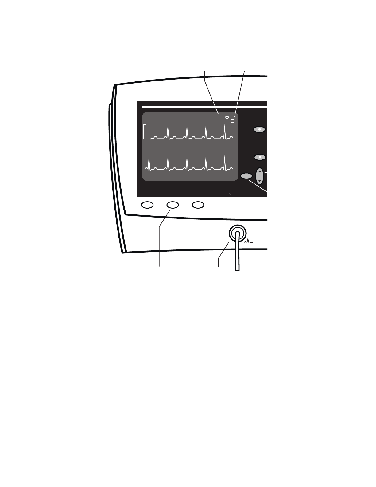
2.3 Monitoring Heart Rate and the ECG Waveform
The trace displays one of the ECG leads. This lead is indicated above the right end of the trace, near the
♥
symbol and heart rate value. Choose the lead with the Lead Select button. Heart rate is displayed at
the right.
ECG displays – The ECG waveform is always
displayed on the upper half of the screen. The
ECG waveform cascades (continues) from the
upper half of the screen to also appear at the
bottom portion when other waveforms are not
selected in Advanced Configuration. The Heart
Rate is displayed above the right end of the top
waveform, near the ♥ symbol. The symbol for
the selected ECG lead is shown to the right of
the Heart Rate.
There is always a scale reference bar shown to
the left of the upper ECG waveform. This scale
bar has a height that represents a 1 mV signal.
The apparent height of the scale bar will vary
depending upon the ECG gain setting being
used, but will always correspond to a 1mV
signal.
Selecting leads - Press Lead Select to change
the lead display. The ECG function can use
either 3 wire leads - I, II, III , or 5 wire leads I, II, III, aVR, aVL, aVF, and V. 3 wire or 5
wire lead setting is selected in the Advanced
Configuration menu.
Note: When using 3 wire leads, the ECG lead
set must be set correctly. Incorrect results
and noisy waveforms can be obtained if the
system is configured for 5 wire leads when
using 3 wire leads.
Alarms - When either of the Heart Rate limits
are exceeded, an audible alarm sounds and the
affected measurement flashes. If the Print On
Alarm configuration is set to Yes, this alarm will
trigger an automatic print. You can silence the
Heart Rate alarm, and all alarms, by pressing the
large blue
instrument. This will silence all alarms for 60,
90, or 120 seconds, depending on the setting
selected in Advanced Configuration. However,
any measurement still outside the set limits will
flash. When alarms are silenced, they do not
trigger a Print On Alarm.
To suspend the Heart Rate alarms, press the
ALARMS Off
button lights. A suspended alarm will still flash
if it goes outside the range of the limits, but it
will not sound the audible alarm. When an alarm
is suspended, it will not trigger a Print On
Alarm.
Note: The Heart Rate alarm can be suspended
for only 3 minutes when the language setting
is configured to “Francais”. If the language
is set to any other language, pressing the
ALARMS Off
until you remove the suspension.
If ECG is inactive for any reason, the Heart Rate
display will be dashes “---” and the Heart Rate
alarm will respond to the pulse oximetry rate.
Setting alarm limits –To set the Heart Rate
alarm limits, use the
the left side of the monitor to follow these steps:
• Press the left Select button to cycle through
• Each push of Select moves you to the next
• Press the Set button up or down to raise or
Silence button at the right side of the
HR
button so the red LED in the
HR
button will suspend the alarm
Select and Set buttons on
HI and LO, Heart Rate HI and LO,
MAP
Respiration
623xx)
LO.
HI and LO (models 622xx or
, then (model 623xx) CO
HI and
2
limit. Stop at the limit you want to set. The
measurement and
HI or LO will flash,
indicating which limit is being changed.
15
Page 28

lower the alarm limit. (When you come to
the end of the range, the numbers will stop
changing).
• Press the Select button again to go to the
next limit, or press it several times until
none of the measurements flash and no
LO indicators are lit. The instrument is now
in its normal measurement mode. (If you do
not press any button for 10 seconds, the
instrument will automatically revert to its
normal measurement mode).
HI or
16
Page 29
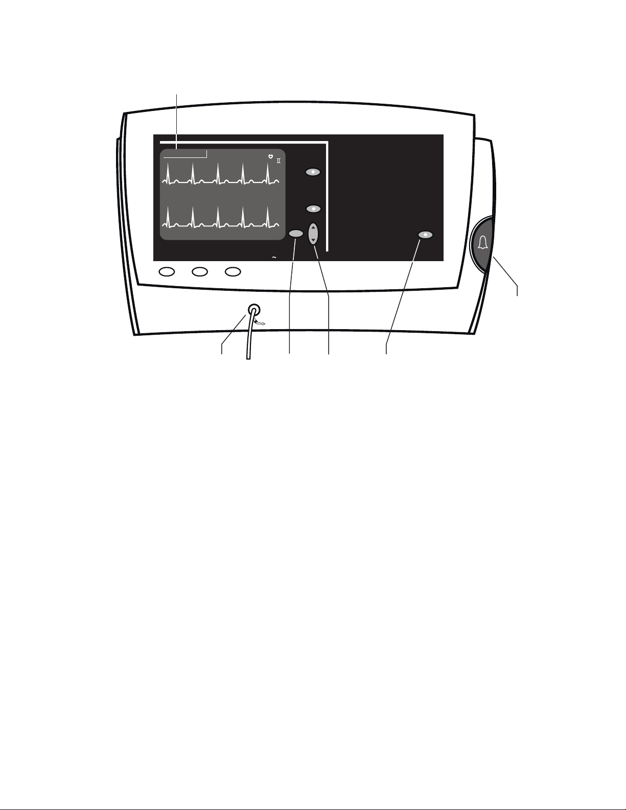
e
Heart Rate Selected Lead
Select
HR ALARMS
Off
2
/ RESP
CO
ALARMS
Off
S
Trend
Lead Select
Lead Select Print
80
AC
ECG
Connector
Atlas Monitor showing ECG waveform display, controls, and ECG
connector
17
Page 30
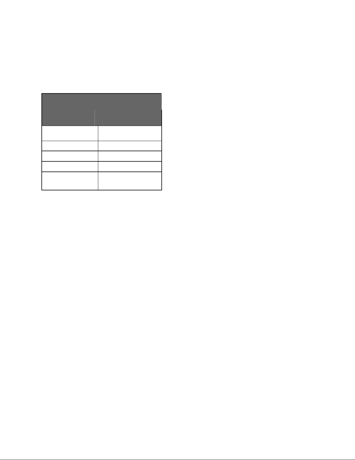
ECG settings in Advanced Configuration The five settings in the Advanced Configuration
menu associated with the ECG are listed in this
table:
Advanced Configuration
ECG setting
ECG gain automatic |
ECG lead set 3 wire | 5 wire
ECG speed 6.25 | 12.5 | 25 mm/s
ECG bandwidth Monitor | Extended
Second trace
selection
Possible values
10 mm/mV
ECG | SpO2 |
Respiration | CO
2
You can change the ECG settings in Advanced
Configuration:
• Press the Date/Time button.
• Press
• Use either
• Use the
• Press
ECG gain - The height of the vertical ruler that
appears to the left of the ECG waveform
indicates a 1 mV amplitude and is 10 mm high if
10 mm/mV gain is chosen. When automatic
gain is selected the ruler height will vary, but it
will always indicate a 1 mV signal size. The
ruler size is automatically increased or decreased
to scale to a particular set of waves, but the
vertical line still indicates the same amplitude of
1 mV.
ECG lead set - The Atlas Monitor allows for
both 3 wire and 5 wire ECG lead sets.
Trend.
Select button to highlight ECG
gain, ECG lead set , ECG speed, ECG
bandwidth, or Second trace selection.
Set button to change any of these
values.
Trend to exit Advanced Configuration
Note: When using 3 wire leads, the ECG lead
set must be set correctly. Incorrect results
and noisy waveforms can be obtained if the
system is configured for 5 wire leads when
using 3 wire leads.
ECG speed - The amount of ECG waveform
shown on the CRT is determined by the trace
speed. A slower trace speed means more
seconds of waveform are shown on the CRT.
ECG bandwidth - The ECG waveform can be
displayed and printed in either Monitor or
Extended bandwidth. Monitor mode allows for
a clearer picture of the waveform by filtering out
noise. Extended mode, usually used with
cardiac paced patients, shows the finer nuances
of ECG waveform, facilitating the detection of
conditions such as ischemia.
Note: Detection of ischemia is the interpretation
of the clinician only, the Atlas Monitor does
not provide automated ischemia detection.
Note: It is normal for the ECG baseline to
wander slightly in Extended bandwidth.
Pacemaker signals – The Atlas Monitor
displays pacemaker signals exactly as they are
captured. There is no option to display symbolic
pace indications. Use Extended bandwidth for
enhanced display of pacemaker signals.
18
Page 31

2.4 Monitoring Impedance Respiration (Models 622xx & 623xx)
The lower trace can display the Impedance Respiration waveform if this is chosen in Advanced
Configuration. In this case, the Respiration Rate is displayed above the right side of the waveform. The
Impedance Respiration waveform is always derived from Lead I (RA-LA).
What is it? - Respiration Rate is measured with
the ECG leads. As the chest expands and contracts
during the respiration cycle, the resistance, or
impedance, between the RA-LA electrodes (
) changes. The result of these changes indicates
I
Lead
the respiration rate.
For best performance in monitoring impedance
respiration rate, change the LA and RA electrode
placement to the mid-axillary line on each side of
the chest as shown in the section on connecting
the ECG.
Where is it? - In Atlas Monitor model 622xx, the
lower trace normally shows cascading ECG. In
Atlas Monitor model 623xx, the lower trace
normally displays the ETCO
waveform.
2
However, the lower trace can instead show
Impedance Respiration, if it is chosen in
Advanced Configuration.
How to display it – You can change the Second
trace selection settings in Advanced
Configuration:
• Press the
• Press
• Use either
Date/Time button.
Trend.
Select button to highlight Second
trace selection.
• Use either
from the choices ECG, SpO
CO
2
• Press
Set button to choose Respiration
, Respiration,
2
(model 623xx).
Trend to exit Advanced Configuration.
Impedance Respiration is sensitive to patient
movement, making it less accurate than ETCO
2
for measuring the breath rate. For this reason,
model 623xx users often prefer to view the
ETCO
waveform and let the monitor measure
2
breath rate from this source.
Alarms - When either of the respiration rate limits
are exceeded, an audible alarm sounds and the
affected measurement flashes. If the Print On
Alarm configuration is set to Yes, this alarm will
trigger an automatic print. You can silence the
respiration alarm, and all alarms, by pressing the
large blue
Silence button at the right side of the
instrument. This will silence all alarms for 60, 90,
or 120 seconds, depending on the setting selected
in Advanced Configuration. However, any
measurement still outside the set limits will flash.
When alarms are silenced, they do not trigger a
Print On Alarm.
To suspend the respiration rate alarms, press the
CO2/RESP ALARMS Off (RESP ALARMS Off)
button so the red LED in the button lights. A suspended alarm will still flash if it goes outside the
range of the limits, but it will not sound the
audible alarm. When an alarm is suspended, it will
not trigger a Print On Alarm.
Note: The respiration rate alarm can be suspended
for only 3 minutes when the language setting is
configured to “Francais”. If the language is set
to any other language, pressing the
ALARMS Off
button will suspend the alarm
CO2/RESP
until you remove the suspension.
Warning: Impedance Respiration rate
measurement and alarm capability are active
ONLY when the second trace option is set to
Respiration. Should the operator change from
viewing the Respiration waveforms and breath
rate to another selection (SpO
, CO2 or ECG)
2
the Respiration rate monitoring and alarm
capability will be disabled. This occurs even if
the ECG cable is still inserted into the Monitor.
19
Page 32

Atlas Monitor showing Impedance Respiration waveform display,
controls, and ECG connector
Setting alarm limits –To set the Respiration
alarm limits, use the
Select and Set buttons on
the left side of the monitor to follow these steps:
• Press the left Select button to cycle through
HI and LO, Heart Rate HI and LO,
MAP
Respiration
only) CO
HI and LO, then (model 623xx
HI and LO.
2
• Each push of Select moves you to the next
limit. Stop at the limit you want to set. The
measurement and
HI or LO will flash,
indicating which limit is being changed.
• Press the Set button up or down to raise or
lower the alarm limit. (When you come to
the end of the range, the numbers will stop
changing).
• Press the Select button again to go to the
next limit, or press it several times until
none of the measurements flash and no
LO indicators are lit. The instrument is now
HI or
in its normal measurement mode. (If you do
not press any button for 10 seconds, the
instrument will automatically revert to its
20
normal measurement mode).
Page 33

2.5 Monitoring Temperature (Models 622xx & 623xx)
°
The Temperature, measured on the skin surface with a skin sensor, is displayed in
Advanced Configuration. There are no audible alarms for Temperature. An invalid temperature reading
is indicated by dashes “---” in the numeric display.
Temperature can be measured with a skin sensor.
No alarms – There are no temperature alarm
limits and no audible alarms for temperature. If
there is no temperature probe connected when the
monitor is first turned on, the TEMP display will
be blank.
If the probe becomes disconnected from the
patient or the monitor, the TEMP display will
show steady dashes “---”, but there will be no
alarm.
Changing the scale – The temperature display
can be in °F or °C, as selected in Advanced
Configuration.
You can change the Temperature units setting in
Advanced Configuration:
• Press the
• Press
• Use either
Date/Time button.
Trend.
Select button to highlight
Temperature units.
• Use either
• Press
Set button to choose °F or °C.
Trend to exit Advanced Configuration.
Note: The temperature display is blank at power-
on until a temperature probe has been detected.
F or °C, as chosen in
21
Page 34

Temperature
Units
TEMP
F
C
Temperature
Connector
Atlas Monitor showing Temperature display and connector
22
Page 35

2.6 Monitoring CO2, Respiration Rate, and the ETCO2 Waveform
(Model 623xx)
The lower trace displays the ETCO
or SpO
in its place if desired. The CO2 measurement is shown above the right end of the trace, and
2
Respiration Rate appears on the left. You can set alarm limits for both of these measurements.
What is displayed – In the Atlas Monitor model
623xx, one of the lower trace alternatives to the
cascading ECG includes the CO
Respiration Rate is displayed above the left end
of this trace. Carbon Dioxide concentration
displayed above the right end of the trace. CO
can be displayed in units of %, mmHg, or kPa.
There are high and low alarm levels for
Respiration Rate and for CO
concentration.
2
Note: the watertrap must be installed for the CO
displays to be active. If the watertrap is not
installed, the Atlas Monitor will display
cascading ECG.
Warning: End tidal carbon dioxide (ETCO
and breath rate measurement and alarm
capability are active ONLY when the second
trace option is set to CO
. Should the
2
operator change from viewing the ETCO
and breath rate waveforms and data to
another second trace selection (SpO
Respiration or ECG) the CO
rate monitoring and alarm capability will be
disabled. This occurs even if the watertrap
and cannula are still inserted into the
Monitor.
How it works - The CO
sensor is based on a
2
single beam, single frequency Infra-Red (IR)
source and a dual thermopile detector. CO
measurement is based on the IR absorption
characteristics of CO
molecules. The CO2
2
sensor uses non-dispersive IR spectroscopy to
measure the number of CO
the sample gas. CO
gas has a unique absorption
2
molecules present in
2
band which is related to a CO
composition and mass. CO
gas concentration is
2
waveform, although you can display Impedance Respiration, ECG,
2
measured by detecting absorption in this band.
waveform. The
2
is
The IR absorption in the CO
may be affected by a number of factors that
skew the CO
measurement. The Atlas Monitor
2
automatically compensates for some of these
2
factors. Water vapor compensation accounts for
wavelength band
2
the effect that water vapor has on the IR
absorption characteristics of CO
2
During normal sidestream operation, CO
measurements are adjusted mathematically to
compensate for this effect.
2
Alarms - When any of the CO2 or Respiration
Rate limits are exceeded, an audible alarm
sounds and the affected measurement flashes. If
the Print On Alarm configuration is set to Yes,
)
2
this alarm will trigger an automatic print. You
can silence the CO
pressing the large blue
alarm, and all alarms, by
2
Silence button at the
right side of the instrument. This will silence all
2
alarms for 60, 90, or 120 seconds, depending on
the setting selected in Advanced Configuration.
,
2
and breath
2
However, any measurement still outside the set
limits will flash. When alarms are silenced, they
do not trigger a Print On Alarm.
To suspend both the CO
alarms, press the
CO2/RESP ALARMS Off
and Respiration Rate
2
button so the red LED in the button lights. A
suspended alarm will still flash if it goes outside
the range of the limits, but it will not sound the
audible alarm. When an alarm is suspended, it
2
will not trigger a Print On Alarm.
Note: The CO
and Respiration Rate alarms can
2
be suspended for only 3 minutes when the
language setting is configured to “Francais”.
If the language is set to any other language,
molecule’s
2
pressing the
CO2/RESP ALARMS Off button
will suspend the alarm indefinitely.
molecules.
2
23
Page 36

Atlas Monitor model 623xx showing ETCO2 waveform display,
controls, and watertrap connector
Setting alarm limits –To set the CO2 and
Respiration Rate alarm limits, use the
and
Set buttons on the left side of the monitor to
follow these steps:
• Press the left Select button to cycle through
HI and LO, Heart Rate HI and LO,
MAP
Respiration
• Each push of Select moves you to the next
limit. Stop at the limit you want to set. The
measurement and
indicating which limit is being changed.
• Press the Set button up or down to raise or
lower the alarm limit. (When you come to
the end of the range, the numbers will stop
changing).
• Press the Select button again to go to the
HI and LO, then CO
HI or LO will flash,
Select
HI and LO.
2
next limit, or press it several times until
none of the measurements flash and no
LO indicators are lit. The instrument is now
in its normal measurement mode. (If you do
not press any button for 10 seconds, the
instrument will automatically revert to its
normal measurement mode).
HI or
24
Page 37

3 Managing the Alarms
Four types of events can cause an alarm: 1) the patient’s measurement is outside the limits you set; 2) the
measurement is invalid; 3) the instrument is malfunctioning; 4) the battery is low. You can silence alarms
for a period (60, 90, or 120 seconds) by pressing the Silence button, or you can suspend the audible
signal for any patient alarm or measurement invalid alarm for 3 minutes under the “Francais” language
setting or indefinitely with other language setting configurations. Atlas can be configured to print
automatically when an alarm occurs. You can also adjust the alarm volume.
With this monitor, it is easy to set alarm levels, to
silence alarms for a short period, and to suspend a
selected measurement from triggering the audible
alarm.
Alarm types – Three types of events cause an
audible alarm:
• A Patient Alarm is triggered by a vital
measurement registering outside the limits
you set. That measurement display will flash
and, if the measurement is not suspended or
silenced, an audible alarm will sound.
• A Measurement Invalid Alarm means the
instrument is working properly, but something
is wrong with one of the measurements. This
could be caused by one of the leads coming
off the patient, or by the cable connection to
the instrument coming out. This alarm can
also mean that the actual patient vital sign is
outside of the range of measurement of the
Atlas Monitor. These events cause an audible
alarm, a message on the screen, and the
affected display turns to dashes “---” which
flash.
• An Instrument Problem Alarm means the
instrument has found an internal problem.
These alarms are very rare. They produce an
audible alarm, a message on the screen, and
the affected measurement display will be
blank.
• A Battery Low Alarm means that the battery
(models 622xx and 623xx) is running low and
has 10 or fewer minutes of life remaining.
To help you determine what an alarm means,
there are four principal alarm sounds. The four
alarm types and their visual indications are shown
in the table.
Print On Alarm - If the Print On Alarm
configuration is set to Yes in the Advanced
Configuration screen, then a new Patient Alarm or
a new Measurement Invalid Alarm will trigger a
print of the currently configured waveforms and
current measurements. The alarming values will
be marked with asterisks in the printed report. A
Print On Alarm will not occur for low battery
alarms or for instrument problem alarms. If alarms
are silenced or suspended, a Print On Alarm will
not occur, but if the alarm is still active when the
silence period is over or when the alarm is
unsuspended, a Print On Alarm will occur.
Alarm volume – The Alarm Volume is controlled
by a button labeled with a bell icon. Eight volume
settings are provided.
Note: The alarm volume cannot be turned
completely off with this button.
Saving volume settings – You can save your
volume settings for alarms and for pulse tone after
you change them, so that they become the initial
settings every time the Atlas Monitor is powered
on. After making the alarm and pulse volume
changes, press Date/Time to display the Other
Options menu, and press Print (or Freeze) to save
your settings. Press Date/Time to return to the
main screen. You may repeat this whenever you
want to change your settings.
Nurse Call – All alarms activate the Nurse Call
relay through a rear panel connector of models
622xx and 623xx. This relay can be connected to
either a normally open or a normally closed hospital
system to alert the central nurse station. The Nurse
Call relay will be activated for any condition that
causes an audible alarm at the unit. This means
25
Page 38
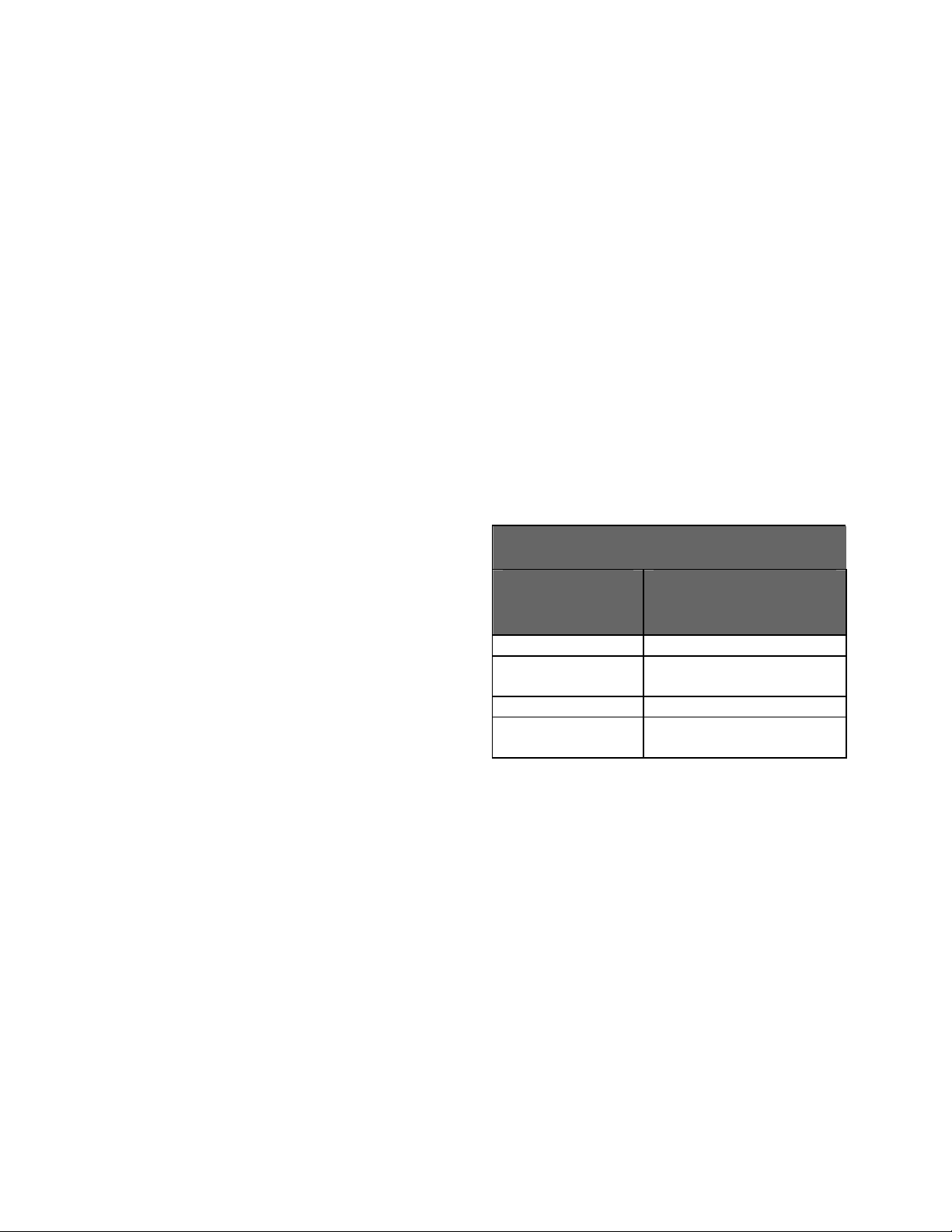
suspended alarms will not alert the nurse station, nor
will alarms that occur during a silence period, until
the period is over. See the Technical Service Manual
for details on the Nurse Call relay.
Warning: it is the user’s responsibility to
implement the interface between the Nurse
Call system and the Welch Allyn Atlas
Monitor. It is also the user’s responsibility to
adequately test the interface between the
Monitor and the Nurse Call system to ensure
that the desired functionality is operational.
Silencing alarms – You can turn off the audible
alarm sound for a brief period by pressing the
Silence button. The LED will light and no audible
alarms will be heard for 60, 90, or 120 seconds,
depending on the alarm silence duration. When
alarms are silenced, they will not trigger a Print
On Alarm. When the silence period is over, an
alarm that is still active will trigger a Print On
Alarm if the Print On Alarm configuration is set
to Yes.
To set the alarm silence duration, enter Advanced
Configuration by pressing
pressing
Trend. Use either Select button to
highlight Silence duration. Press the
to choose 60, 90 or 120 seconds. Exit by pressing
Trend button again.
the
Pressing the
Silence button silences all alarms,
including new alarm events that may occur after
you press the button. However, even with no
sound, those measurements that are outside their
limits will still be noticeable, by the flashing
numbers or dashes, or blank displays.
At the end of the silence period, when the LED on
Silence button turns off, any measurement
the
still outside its limits will cause another audible
alarm.
If you press the
Silence button during the silence
period, while the bell icon is still lit, the silence
period ends, and any alarm condition, new or old,
will sound the audible alarm.
Suspending alarms – Suspending an alarm
Date/Time, then
Set button
means preventing a patient measurement from
triggering an alarm. Suspended alarms are “off” in
the sense that they will not sound the alarm for a
period of time, but they are “on” in the sense that
the patient’s vital signs are still measured and
displayed. Suspended measurements flash if they
are outside the limits, but they do not cause an
alarm sound. When an alarm is suspended, it will
not trigger a Print On Alarm. When the alarm is
unsuspended, an alarm that is still active will
trigger a Print On Alarm if the Print On Alarm
configuration is set to Yes.
To suspend a measurement alarm, press the
appropriate ALARMS Off button and the red
LED in the center of the button will light. There
are 4 ALARMS Off buttons, and they suspend
the groups of measurements in the following
table:
Suspending Alarms
“Off” button
Suspends alarm
label
HR ALARMS Heart Rate
CO2/RESP
ALARMS
ETCO2 and Respiration
Rate
SpO2 ALARMS Oximetry and Pulse Rate
BP ALARMS Systolic, Diastolic and
MAP
Removing suspension of alarms – When the
“Francais” language option is selected in the
Advanced Configuration Menu, the alarms can
only be suspended for 3 minutes. To remove
suspension before the 3 minutes have elapsed,
press the
ALARMS Off button again.
When the Atlas Monitor is set to all other
languages including Canadian French, alarms will
remain suspended until they are turned back on or
the monitor is turned off. To remove suspension,
press the
ALARMS Off button again. Remember,
suspended alarms do not time out automatically.
Alarms are not suspended at power up, but an
alarm will not sound until valid measurements
have begun.
26
Page 39

Alarm Conditions
Alarm type
Patient Alarm; a vital
sign measurement is
outside limits
Sensor
disconnected from
patient
Measurement
outside the range of
the instrument
Temperature probe
disconnected*
Instrument problem Affected
Battery low Tone once every 2
Battery very low Tone once every
*The temperature display remains blank until a probe is detected for the first time after turning on the
monitor.
Normal operation
Numbers flash
Audible alarm –
medium pitched
tone once per
second
Print On Alarm if
configured.
Flashing “---”
Audible alarm – high
pitched tone twice
per second
Message on screen
Print On Alarm if
configured.
Flashing “---”
Audible alarm – high
pitched tone twice
per second
Message on screen
Print On Alarm if
configured.
Solid “---”
No audible alarm
Message on screen
measurement blank
Audible alarm – very
high pitched tone,
very rapid rate
Message on screen
minutes
Message on screen
minute
Message on screen
Numbers flash
No audible alarm
No Print On Alarm
Flashing “---”
No audible alarm
Message on screen
No Print On Alarm
Flashing “---”
No audible alarm
Message on screen
No Print On Alarm
Solid “---”
No audible alarm
Message on screen
Affected
measurement blank
No audible alarm
Message on screen
No audible tone
Message on screen
No audible tone
Message on screen
Silenced
Suspended
Numbers flash
No audible alarm
No Print On Alarm
Solid “---”
No audible alarm
No message on
screen
No Print On Alarm
Solid “---”
No audible alarm
No message on
screen
No Print On Alarm
Affected
measurement blank
No audible alarm
No message on
screen
27
Page 40

t
c
c
PG 3-6
Flashing Heart
Rate Limit
SpO
2
+
-
and Set
TEMP
Systolic
HI
Diastoli
LO
Select
Se
BP Start/Can
+
-
PULSE
(bpm)
HR ALARMS
HI
12
Trend
RR
Lead Select Print
170
23
%
AC
Select
Off
SpO2%
CO
2
/ RESP
ALARMS
Off
SpO2ALARMS
Off
Set
Alarm Select
Flashing Systolic
Pressure Limit
PULSE
(bpm)
70
23
Print
HR ALARMS
Off
2
%
SpO
CO
2
/ RESP
ALARMS
Select
Off
SpO2ALARMS
Off
Set
%
AC
TEMP
Systolic
HI
Diastolic
LO
Select
F
C
(mmHg)
HI
LO
(mmHg)
HI
LO
BP ALARMS
Off
Set
Off 1 3 5
10 15 30 60
AutoBP Start/Cancel
SpO
2
+
+
-
2
-
Alarm Select
and Set
Atlas Monitor showing alarm setting displays and controls
28
Page 41

3.1 Patient Alarms
Patient alarms sound when one of the patient’s vital measurements is registering outside the limits you
have set. You can set high and low alarm limits for most of the measurements. Setting and checking the
alarm limits can be easily done from the front panel. The alarm settings can be saved as defaults by
accessing a menu. Patient alarms trigger a Print On Alarm, if Print On Alarm is configured.
A Patient Alarm is a signal that some vital
measurement is outside the limits that were set
by you. Patient alarm limits assume preset
values when the monitor is first turned on and it
is easy to change the limits at the front panel.
Setting alarm limits – The front panel of the
monitor has 2 sets of Select and Set buttons.
One set is on the right side of the monitor, and
one set is on the left side. To set a patient alarm
limit, use one of the Select buttons and follow
these steps:
• Press the
Select button on the side of the
monitor closest to the measurement you
want to change several times until the limit
you want to change flashes. Successively
pressing this button cycles through the
settings for each different measurement.
These numbers and the
HI or LO indicator
will slowly flash. The flashing numbers
show the current alarm limit.
• While the alarm limit you want to change is
flashing, press the top or bottom half of the
Set button. This changes the alarm limit.
Note: The alarm limits do not wrap around at the
upper and lower end of their legal values.
Instead, the number stops changing when you
reach the upper or lower measurement limit
of the instrument.
• When you are satisfied with this alarm limit,
Select again to move to another
press
patient alarm.
• To exit alarm limit setting and return to
normal mode, press Select until there are no
alarm limits or
HI or LO indicators flashing.
Note: If the buttons are not pressed for 10
seconds, the unit will automatically revert to
its normal mode.
Silencing patient alarms – The
Silence button
turns off all audible alarms - patient alarms and
other types - for a short period. Any vital
measurement that is outside its limits will flash,
showing which measurement is out of range.
Any other measurements that go outside their
limits during the current silence period will also
flash, but will not trigger the audible alarm
during the silence period. When alarms are
silenced, they will not trigger a Print On Alarm.
When the silence period is over, an alarm that is
still active will trigger a Print On Alarm if the
Print On Alarm configuration is set to Yes.
Suspending patient alarms – You can suspend
patient alarms individually, which means that
the specific measurement will not sound the
audible alarm when it goes outside the limits.
However, this value will still flash whenever it is
outside the limits, giving you a visual indication
of an alarm condition. When an alarm is
suspended, it will not trigger a Print On Alarm.
When the alarm is unsuspended, an alarm that is
still active will trigger a Print On Alarm if the
Print On Alarm configuration is set to Yes.
ALARMS Off buttons to suspend alarms are
The
shown in the table:
29
Page 42
Suspending Alarms
“Off” button
Suspends alarms
label
HR ALARMS Heart Rate
CO2/RESP
ALARMS (RESP
ALARMS)
SpO2 ALARMS Oximetry and Pulse Rate
BP ALARMS Systolic, Diastolic and
Press the appropriate
suspend the audible alarm for a selected
measurement. The LED in the button will light,
indicating that the alarm is off. If this
measurement goes outside the set limits, the
displayed value will flash. When you remove
the suspension, the light will turn off.
Remove suspension under the Francais
language setting – When the “Francais”
language option is selected in the Advanced
Configuration Menu, the alarms can only be
ETCO2 and Respiration
Rate
MAP
ALARMS Off button to
suspended for 3 minutes. At the end of that time
the suspension will be removed. You can
remove the suspension before the 3 minutes
have elapsed by pressing the
button again.
Remove suspension under other language
settings – When the Atlas Monitor is set to all
other languages including Canadian French,
alarms will remain suspended until they are
turned back on or the monitor is turned off. To
remove suspension, press the
button again. Remember, suspended alarms do
not time out automatically. Alarms are not
suspended at power up, but an alarm will not
sound until valid measurements have begun.
Saving alarm settings – You can save your
alarm settings after you change them, so that
they become the initial settings every time the
Atlas Monitor is powered on. After making the
alarm limit changes, press
the Other Options menu, and press
Freeze) to save your settings. Press Date/Time
to return to the main screen. You may repeat this
whenever you want to change your settings.
ALARMS Off
ALARMS Off
Date/Time to display
Print (or
3.1.1 Factory Default Patient Alarm Settings
Measurement
Heart Rate 45 beats/minute 140 beats/minute
Blood Pressure – Systolic 70 mmHg 200 mmHg
Blood Pressure – Diastolic 50 mmHg 155 mmHg
Blood Pressure – MAP 60 mmHg 180 mmHg
SpO2 85% Respiration Rate 7 breaths/minute 30 breaths/minute
CO2 25 mmHg 60 mmHg
Low alarm default
30
High alarm default
Page 43

3.2 Measurement Invalid Alarms
Invalid measurements could be caused by problems such as an ECG lead detaching from the patient or by
a kinked ETCO
other alarms. You can quiet these with the Silence button, and you can suspend the alarm with the
appropriate
vital sign has exceeded the measurement capability of the Atlas Monitor. Measurement Invalid alarms
trigger a Print On Alarm, if Print On Alarm is configured.
The Measurement Invalid Alarm is indicated by
distinctly different alarm tones and by a message
on the screen. A variety of conditions might
cause this type of alarm, such as:
• the ETCO
• one of the ECG leads has fallen off the
patient.
• the ETCO
replaced.
• one of the sensor cables is unplugged from
the monitor.
• the blood pressure cuff is detached, has a
leak, or is kinked.
• the patient’s vital sign measurement is
outside the range supported by the
instrument.
Any of these Measurement Invalid conditions
will cause four things to happen:
• The audible alarm will sound, if the event
occurs outside a silence period.
• The affected measurement will show
flashing dashes “---”.
• A message appears on the screen.
• A Print On Alarm will occur if Print On
Alarm is configured and alarms are not
suspended or silenced.
Silencing alarms – You can silence the audible
alarm with the
This will not erase the message from the screen.
During this period, you should try to correct the
problem by reconnecting the cable or patient
lead, or changing the watertrap, if appropriate.
At the end of the silence period, if the condition
still exists, the audible alarm will announce the
problem again. When alarms are silenced, they
will not trigger a Print On Alarm. When the
sample line. Such conditions sound an alarm with a tone and pattern distinct from the
2
ALARMS Off button. A Measurement Invalid alarm could also indicate that the patient’s
silence period is over, an alarm that is still active
will trigger a Print On Alarm if the Print On
Alarm configuration is set to Yes.
sample line is kinked.
2
Suspending alarms – If the problem cannot be
corrected, or if you want to ignore this
measurement, you can suspend a measurement
watertrap is full and must be
2
invalid alarm by pressing the corresponding
ALARMS Off button. This will erase the
message from the screen and, depending on the
language setting, prevent further audible alarms
and messages for this condition. The dashes “--” will be solid, not blinking. A Print On Alarm
will not occur when an alarm is suspended. If
the alarm is still active when it is unsuspended, a
Print On Alarm will occur if it is configured.
The ALARMS Off buttons are:
HR ALARMS Off for heart rate.
•
SpO2 ALARMS Off for oximetry levels and
•
pulse rate.
BP ALARMS Off for blood pressure.
•
RESP ALARMS Off for respiration rate
•
(model 622xx). In model 623xx, this is
CO2/RESP ALARMS Off, and it suspends
alarms for respiration rate and CO
levels.
2
Note: Individual alarms can be suspended for
only 3 minutes when the language setting is
configured to “Francais”. If the language
Silence button for a short period.
setting is set to any other language, pressing
ALARMS Off button will suspend the
the
corresponding alarm until you remove the
suspension.
Note: The
Temperature measurement never
produces an audible alarm. If the temperature
probe disconnects from the patient, the display is
replaced by solid dashes “---”.
31
Page 44

3.3 Instrument Problem Alarms
Instrument Problem Alarms, although they rarely occur, are of three types: 1) the Atlas Monitor detected
an internal fault during power-on self test; 2) the Atlas Monitor detected an internal fault during use; 3)
the Atlas Monitor reports that it lost power while in use the last time it was operating. Instrument
Problem Alarms do not trigger a Print On Alarm.
You will rarely see an Instrument Problem Alarm.
These alarms indicate the failure of some internal
circuitry. The Atlas Monitor performs a SelfCheck when it is turned on. If it finds something
that does not respond correctly to the tests, an
Instrument Problem Alarm will be reported.
Problems detected at power-on will produce an
error message telling you what is wrong, but will
not sound an alarm. Also, the affected
measurement indicator will be blank. Problems
detected during use will produce an error message
and sound the Instrument Problem Alarm.
When a problem is detected by the Self-Check,
the rest of the instrument may not be affected, so
in most cases, you can use the monitor for the
other measurements. (Be sure to contact the
Welch Allyn Technical Service Department).
occur when the system is plugged in and turned
back on.
A message will appear reporting that the power
was interrupted and settings were lost. The Atlas
Monitor may not remember changes that you
made to alarm limits and Advanced Configuration
menu entries during the last session. You should
review your settings to ensure that you have the
proper values set.
The alarm and error message will clear when you
press any button on the Atlas Monitor.
The power failure alarm should not occur on Atlas
Monitor models 622xx and 623xx because the
built-in battery will keep the system running
during a power failure or power cord being pulled
out.
Silencing alarms – The audible alarm for
instrument problems has a distinctly different
sound from Patient Alarms and from
Measurement Invalid Alarms. Press the
button to silence this alarm for a short period. This
will not erase the message. Press the appropriate
ALARMS Off button to prevent this alarm from
sounding the audible alarm again and to remove
the error message.
Note: If the Atlas Monitor is set the “Francais”
language in the Advanced Configuration
Menu, the
suspend the alarm for 3 minutes.
Power failure – If the AC power to the Atlas
Monitor model 621xx is interrupted when the
monitor is in use, either because of a power failure
or because the AC cord was pulled out without
turning off the Atlas Monitor first, an alarm will
ALARMS Off buttons will only
Silence
32
Page 45

3.4 Battery Alarms (Models 622xx & 623xx)
Battery Alarms indicate that there are 10 or fewer minutes of battery life remaining. When one minute of
battery life remains, a final alarm tone indicates that the Atlas Monitor is about to shut down, and a
Trend report is automatically printed. Battery Alarms do not trigger a Print On Alarm.
Battery problems – When the Atlas Monitor is
running on battery power, it will warn you when
there is less than 10, less than 5, and less than 1
minute of life remaining in the battery.
If you are using battery power, the AC indicator
AC ~) on the front panel will not be lit. The
(
monitor will run on battery power for about one
hour, depending on what patient measurements
are being taken. More power is required by
NIBP than by some of the other measurements
because the air pump is used. This means that if
you are not taking blood pressure readings, the
battery power will last longer. Printing also uses
more power.
Low battery power – When only 10 minutes of
battery power is left, a chime sounds and a
message appears on the screen. The chime will
sound a reminder every two minutes.
Very low battery power - When the battery has
only 5 minutes of power left, a message appears
and a chime sounds every minute.
Battery Depleted - When the battery power is
nearly depleted, the Instrument Problem Alarm
sounds, a message is displayed, and the monitor
will automatically shut off within one minute.
If the Atlas Monitor is equipped with a printer, it
will print out a Trend report before shutting off
if there is any trend data that has not been
printed yet.
Note: If the battery is depleted, it may turn itself
off immediately without warning. This will
occur if the battery is defective or damaged
or if the battery was depleted when you
turned it on. In this case, plug the Atlas
Monitor into AC power and allow the battery
to charge for a few minutes before using the
instrument on AC.
Note: Atlas Monitor model 621xx does not have
a battery option
Note: Repeated total depletion of the battery will
reduce the life of the battery.
Recharging the battery – The battery is
permanently installed. The battery is recharged
whenever the instrument is operating on AC
power.
Note: It takes about five hours to recharge a
battery that is completely depleted to the
80% level. It can take up to 24 hours to
charge a depleted battery to full capacity.
.
33
Page 46
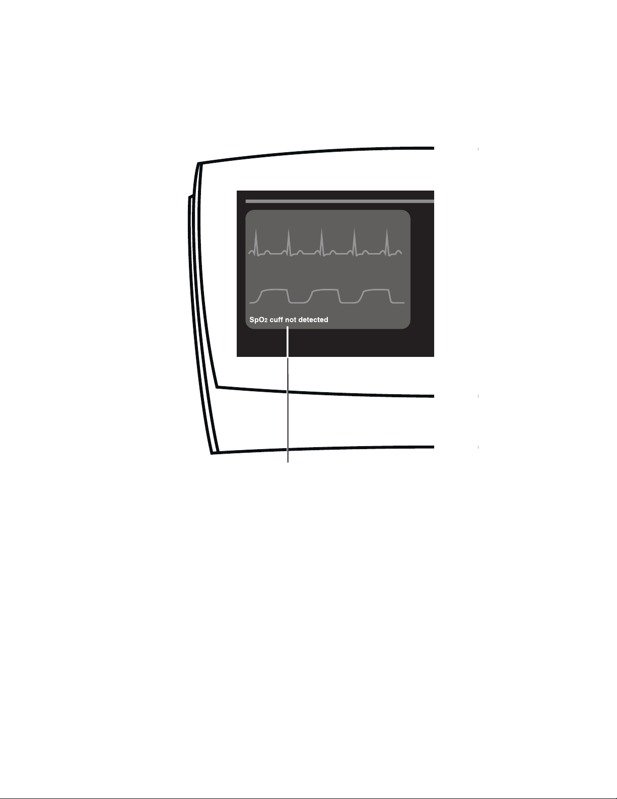
Message Location
Atlas Monitor showing location of system message
34
Page 47
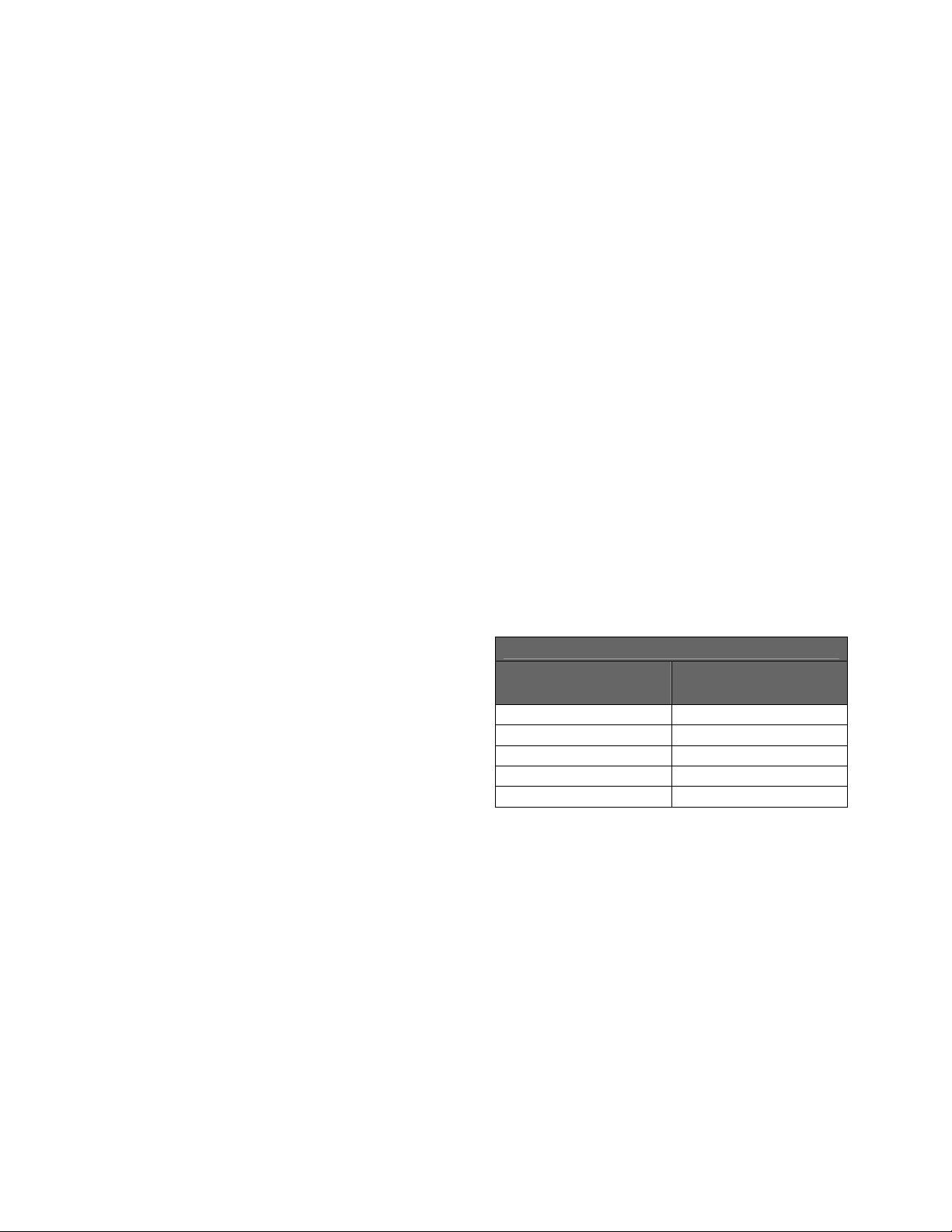
4 Capturing and Displaying Trend Data
Trend data is captured at every Blood Pressure cycle, whether it is automatically timed or manually
initiated. If automatic BP timing is turned off, trend data will be captured every 15 minutes. Display the
data by pressing
The Atlas Monitor can capture and hold up to 144 lines of trend data. This is 36 hours of data at 15
minute intervals. If the intervals are shorter, naturally the total time covered in the trend data is shorter.
A table on this page shows these times.
Viewing trend data - To see trend data, press
Trend button below the screen. The latest
the
measurements are shown at the top of the screen.
Scroll through the trend data with either
button. Return to the waveform screen by
pressing
Trend again. The system will
automatically return to the waveform screen
after 3 minutes of displaying the Trend screen.
All trend data is captured at every blood
pressure cycle whether automatically timed or
manually initiated. Automatic blood pressure
cycles occur at 1, 3, 5, 10, 15, 30 or 60 minute
intervals, as determined by the
located below the blood pressure indicators.
Pressing the
interval. One of these intervals is labeled “X” for
manual timing mode. When this is lit, blood
pressure is not taken automatically, and trend
data is captured every 15 minutes without any
action from you. If the blood pressure
setting is greater than 15 minutes, Trend data
will be captured every 15 minutes.
A blood pressure cycle is manually started by
pressing the
data is captured when this happens. Also, a
blood pressure cycle that has been canceled by
pressing the
by dashes in the trend screen.
Trend data: Printing, Erasing - The only way
to preserve the trend data is to print it. Press
Trend to display the data, then press Print. All
the trend data will be printed; you do not need to
scroll to the other screens of data to print them.
Trend. Then press Print to print it. Trend data is erased when the instrument is shut off.
Trend data is always erased when the instrument
is shut off.
Set
Note: If the monitor was not turned off between
patients, the printed trend data will include
that recorded from previous patients. Trend
data is only erased when the unit is turned
off.
Invalid or missing trend data – Invalid data or
measurements that are not active are displayed
Auto button
Auto button cycles to the next
by dashes in place of the data, on both the Trend
screen and the printout.
Trend Data Capacity
Auto
BP Start/Cancel button. All trend
BP Start/Cancel button is shown
Auto setting
(minutes)
1 2.4
3 7.2
5 12
10 24
15, 30, 60, X 36
Trend capacity
(hours)
35
Page 48
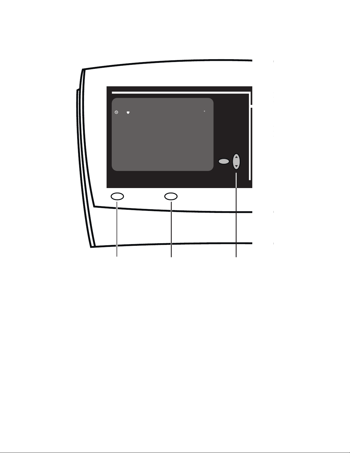
2
%
3:50 70 122/89(--) 92 38 14 98.6
3:40 69 120/84(--) 95 38 12 95.4
3:30 70 119/88(--) 92 33 10 98.6
3:20 70 120/82(--) 95 36 12 96.2
3:10 74 128/86(--) 97 40 16 98.7
3:00 72 122/85(--) 90 38 12 95.6
2:50 70 120/86(--) 98 33 14 98.6
2:40 66 118/80(--) 95 38 10 98.6
2:30 67 120/78(--) 96 37 12 97.5
2:20 70 120/80(--) 95 38 12 98.6
2:10 68 121/85(--) 94 35 10 97.6
BP Sp0
2
CO2
mmHg
RR
F
Select
SpO
Set
Trend
Trend
Print
Print Scroll using Set
Atlas Monitor showing Trend display with associated controls
36
Page 49

5 Using Print and Waveform Freeze
Pressing the
displayed. If a screen of trend data is displayed, all the trend data is printed. Atlas Monitors without
printers have a
Print or Freeze - Except for model 623xx, the
printer is optional. Your Welch Allyn Atlas
Monitor has a printer if there is a button labeled
Print beneath the screen. If there is no printer, this
button is labeled
Printing waveforms - To print the waveforms
and the current measurements, press
the screen shows the waveforms. When you print
waveforms, the waveforms are printed starting
from 9 seconds before you pressed the
button until 6 seconds after you pressed it. The
numeric data is captured and printed at the
moment that the
Printing trend data – To print trend data, press
Trend to view the data on the screen, then press
Print. If trend data is displayed and you want to
print the waveforms, press
the waveforms, then press
Note: If the monitor was not turned off between
patients, the printed trend data will include that
recorded from previous patients. Trend data is
only erased when the unit is turned off.
Printing On Alarm - If the Print On Alarm
configuration is set to Yes in the Advanced
Configuration screen, then a new Patient Alarm or
a new Measurement Invalid Alarm will trigger a
print of the currently configured waveforms and
current measurements. The alarming values are
marked with asterisks in the printed report. The
printout shows 9 seconds of waveform before the
alarm and 6 seconds after the alarm.
Note: If multiple alarms occur at the same time, it
is considered one new alarm and only one print
occurs. If the Atlas is printing and one or more
new alarms occur during the print cycle, an
additional print will occur after the first print.
The Atlas does not issue one print per alarm.
Print button prints the waveforms (and current measurements) if the waveforms are
Freeze button that halts the waveform display for 10 seconds for examination.
A Print On Alarm will not occur for low battery
alarms or for instrument problem alarms. If alarms
are silenced or suspended, a Print On Alarm will
Freeze.
not occur, but if the alarm is still active when the
silence period is over or when the alarm is
unsuspended, a Print On Alarm will occur.
Print while
Print
Freeze - If your monitor does not have a printer, it
Freeze button. Pressing this button halts the
has a
waveforms. You can then examine something on
the screen before it is overwritten. The heart rate
and alarm status are not updated during a freeze.
Print button is pressed.
Three events can end the freeze period and return
the waveforms to the normal, updating mode:
• Pressing
Freeze a second time ends the
freeze period.
Trend to go back to
Print.
• Ten seconds after you press
waveform starts again, automatically.
• Any patient alarm or instrument problem
Freeze, the
alarm that affects the frozen display will
end the freeze period.
Note: No data is lost during the freeze period.
Data is still added to the trend list during this
time.
ECG waveforms – Changing the ECG
bandwidth affects both the displayed and printed
waveforms. The bandwidth choices in Advanced
Configuration are:
• Monitor — a narrow bandwidth, which
produces a cleaner waveform printout.
• Extended — a wider bandwidth, which
allows better viewing of the ST segment
and enhanced detail of the pacemaker
signals in a paced patient.
Note: It is normal for the ECG baseline to wander
slightly in Extended bandwidth.
37
Page 50

M
TE
HI
LO
ECG Lead
ECG Scale
ECG Bandwidth
Print Speed
Respiration
Scale
Respiration
Rate
5mm/mV
.05 - 40Hz
25mm/s
CO
3 Dec 1998 23:40:01
25
2
0
Trend
20
PULSE
(bpm)
SpO2%
CO
RR
Print
21
86
mmHgCO
2
PrintLead Select
31
BP / ( )
23%
120
2
80
92
97
2
CO
2 Waveform
75.1 FRR SpO
Atlas Monitor showing waveform display and printed waveform
record
38
Page 51

5.1 The Printer – Loading Paper and Troubleshooting
The printer has an easy loading feature that doesn’t require threading the paper strip. The lid is popped
open, the thermal paper roll placed into the well with the correct surface towards the front, and the lid is
shut.
The printer - If your Atlas Monitor has this
feature, the printer is located on the top center of
the monitor, covered by a lid. The lid can be
popped open by pushing the button located on the
right side of the lid.
Printer paper – The printer is designed for
thermal paper only. The suggested size for the
paper roll is 2.25 inches (58 mm) in width and
100 feet long. Black ink is recommended.
Loading printer paper – A convenient feature
developed for the Atlas Monitor printer is that no
threading is involved to load the printer paper. To
load paper:
• Open the printer door by pressing on the
button and lifting the lid.
• Place the roll into the printer well with the
thermal, coated side facing out, towards you.
• Pull enough of the paper out so that the strip
will appear beyond the lid.
• Shut the lid to hold down the strip of paper.
Note: The coated side for thermal paper is
markable by a fingernail scratch, the noncoated side is not.
Note: Some manufacturers of paper may produce
paper rolls with the thermal side facing the
inside of the roll. The Atlas Monitor printer
will work with the paper rolled either way, as
long as the thermal side faces towards the front
of the monitor.
If it won’t print – The printer will not print if
there is no printer paper or if the printer door is
open. Check to see that the thermal coated side of
the paper is loaded against the print head (towards
the front).
The end of the paper must extend out of the slot
between the printer door and top of the monitor.
Make sure that the printer door is completely
latched closed.
39
Page 52

Atlas Monitor showing paper being loaded
40
Page 53

6 Connecting to the Patient
The main patient connections are for NIBP, SpO
additionally provide temperature measurement, and the model 623xx adds ETCO
the measurement capabilities of the monitor, you will not have alarms for the measurements you do not
use. You may connect the sensors to the patient before or after you turn the unit on.
, and ECG. Atlas Monitor models 622xx and 623xx
2
. If you do not use all
2
The Welch Allyn Atlas Monitor can only do its
job when it is properly connected to a patient
through the various sensors. You may turn on
the monitor before you connect any leads to the
patient. No alarm will sound until a valid
measurement is made.
Patient connections - The first step is usually to
connect the sensor cables and tubes to the
monitor, and then to the patient. For
convenience, all sensors connect to the front of
the machine. Also, all of the sensors have
different types of connectors, so there should be
no confusion when connecting cables and tubes.
Caution: It is possible to incorrectly connect
the blood pressure tubing to the CO
watertrap. Note that this is not a patient
safety issue, only that ETCO
not be captured and a CO
readings will
2
alarm will sound.
2
It is recommended that the blood pressure
tubing be left connected to the monitor, and
the cuff removed when necessary using the
quick-release connector.
Unused features - You don’t have to use all the
measurement capabilities on the monitor. For
instance, if you want ECG only, just connect
2
these leads. Other features that are not connected
will not produce alarms.
Warning: Impedance Respiration rate
measurement and alarm capability are active
ONLY when the second trace option is set to
Respiration. Should the operator change
from viewing the Respiration waveforms and
breath rate to another selection (SpO
, CO2
2
or ECG) the Respiration rate monitoring and
alarm capability will be disabled. This
occurs even if the ECG cable is still inserted
into the Monitor.
Warning: End tidal carbon dioxide (ETCO
)
2
and breath rate measurement and alarm
capability are active ONLY when the second
trace option is set to CO
operator change from viewing the ETCO
. Should the
2
2
and breath rate waveforms and data to
another second trace selection (SpO
Respiration or ECG) the CO
2
,
2
and breath
rate monitoring and alarm capability will be
disabled. This occurs even if the watertrap
and cannula are still inserted into the
Monitor.
41
Page 54

CO2
SpO2
BP
ECG Temp
Atlas Monitor showing hookup of patient sensors
42
Page 55

6.1 Connecting the NIBP Cuff
Select the proper cuff size (Small, Adult, Large Adult, or Extra Large Adult). Place cuff on patient,
correctly oriented. Connect the tubing to the cuff and to the monitor. Blood pressure measurements can
be taken automatically or manually.
BP cuff sizes - For accurate blood pressure
measurements, it is important to select the proper
cuff size. The Atlas Monitor comes with a Large
Adult cuff. This is the correct cuff for most adults.
(Other sizes are available from Welch Allyn:
Small, Standard Adult and Extra Large Adult).
Warning: The Welch Allyn Atlas Monitor is not
designed for use on children younger than 3
years old.
A good way to assure proper cuff size is to wrap
the cuff around the patient’s upper arm and
inspect it. Welch Allyn cuffs are marked with a
distinct white edge and two divisions that indicate
“range.” When the cuff fits properly, the white
edge marked “Index” will meet the cuff at some
point within the “Range” as shown in the
illustration.
You can also determine cuff size by measuring the
patient’s arm circumference midway between the
elbow and shoulder, and then use the chart below
to select the correct cuff.
ARM CIRCUMFERENCE CUFF
SIZE
Child 6.2 – 8.4 15.8 – 21.3
Small Adult 7.9 – 10.6 20.0 – 27.0
Adult 10.0 – 13.5 25.3 – 34.3
Large Adult 12.6 – 17.1 32.1 – 43.4
Extra Large
Adult
Cuff placement – The preferred blood pressure
measurement site for adults and children is the
upper arm. The arm must be relaxed and
motionless during the reading. For accurate blood
pressure measurements, the upper arm should be
INCHES CENTIMETERS
16.0 – 21.7 40.7 – 55.0
placed at the same elevation as the heart, with the
lower arm passively supported.
• Squeeze any air from the cuff.
• Wrap the cuff snugly around the limb with
room between cuff and arm for only one or
two fingers. If it is too loose, the cuff cannot
inflate properly, and it may result in an
inaccurate reading.
• There is a mark on the cuff indicating the
proper placement, to align the cuff over the
patient’s brachial artery.
• Connect the hose to the cuff and to the front
panel connector. The front panel connector is
a simple, push-on friction fit. The tubing-tocuff connection is a twist-on connection. Be
sure the hose is not kinked or pinched.
Warning: Do not apply the cuff to any extremity
being used for other diagnostic monitoring or
therapeutic intervention, which may include
intravenous infusions, intra-arterial lines, A-V
shunts, PIC lines, and central venous lines.
Warning: Do not place the cuff on any area
where circulation might be compromised. In a
situation involving repeated blood pressure
measurements, monitor the circulation of the
limb to ensure that blood flow is not
compromised.
Warning: Do not place the cuff on an arm that is
also being used for SpO
pressure cuff inflation during SpO
measurement will cause inaccurate SpO
results and false alarms.
monitoring. Blood
2
2
2
43
Page 56

;;;
;;;;
;
;
;;;
;;;
;
;
;
;
;
;;;
;
;
;
;
;
;;;
;;;
;
;
;
;
;
;
;
;
;
;
;;;;;;
;
;;;;;;
;
;;;;;
;;;;;;
;
;
;
;
;
;
;
R
A
N
G
E
A
R
T
ER
Y
3
1
.5
c
ADULT
INDEX
m
M
A
X
S
IZ
E
Correct placement of NIBP pressure cuff
44
Page 57

Blood pressure measurements – Blood
pressure cycling can be scheduled automatically
or started manually, as determined by the choice
selected by the
the monitor, the
Auto button. When you turn on
Auto setting defaults to “X”,
but it remembers the previous setting. Press the
Auto button once to return to the previous
setting, or press it repeatedly to select a new
interval. Or choose “X” for manual operation.
Wait 10 seconds for the selected Auto value to
stop flashing. If any value other than “X” is
selected, the first automatic measurement will
begin 20 seconds after the Auto LED stops
flashing.
If you press
BP Start/Cancel between
automatically timed measurements, the cuff will
begin to inflate immediately and the monitor
will record a new set of measurements. The
manual measurement will not interfere with the
automatic timing unless the next automatic
measurement is scheduled to occur within 30
seconds of the end of the manual measurement.
Pressing
BP Start/Cancel during a blood
pressure measurement will cause the cuff to
deflate immediately, and the reading is canceled.
The trend data for that reading will show as
dashes “---” on the screen and in the printout.
Both Systolic and Diastolic blood pressures are
displayed on the front panel. During
measurement, the Systolic display shows the
cuff pressure as it pumps up and steps down.
Mean Arterial Pressure (MAP) is displayed on
the screen (upper left) only if it is enabled in the
Advanced Configuration menu.
Note: If the language setting is configured to
Chinese, you can configure the Alternate BP
field to display MAP or blood pressure in
kPa on the screen (upper left).
Note: MAP is calculated using the formula: one
third of the Systolic reading plus two thirds
of the Diastolic reading.
Principles of Operation – The Atlas Monitor
uses an ‘oscillometric’ method to measure the
patient’s blood pressure. This technique is
characterized by inflating the blood pressure
cuff until the arterial blood flow is occluded, and
then slowly releasing the cuff pressure and
monitoring the oscillations in the cuff air
pressure due to arterial blood flow pulses. While
the cuff is deflating, the amplitude of the
oscillations are recorded versus cuff pressure.
The systolic measurement is found by noting the
cuff pressure when the pre-maximum
oscillations are at a fixed percentage of the
maximum oscillations. Similarly, the diastolic
pressure is found by noting the cuff pressure
when the post-maximum oscillations are at a
fixed percentage of the maximum oscillations.
If the initial cuff pressure is insufficient to
occlude the arterial blood flow, the instrument
will re-inflate the cuff by approximately 40
mmHg. During deflation, the instrument may
also re-inflate in order to re-measure the
oscillations.
45
Page 58
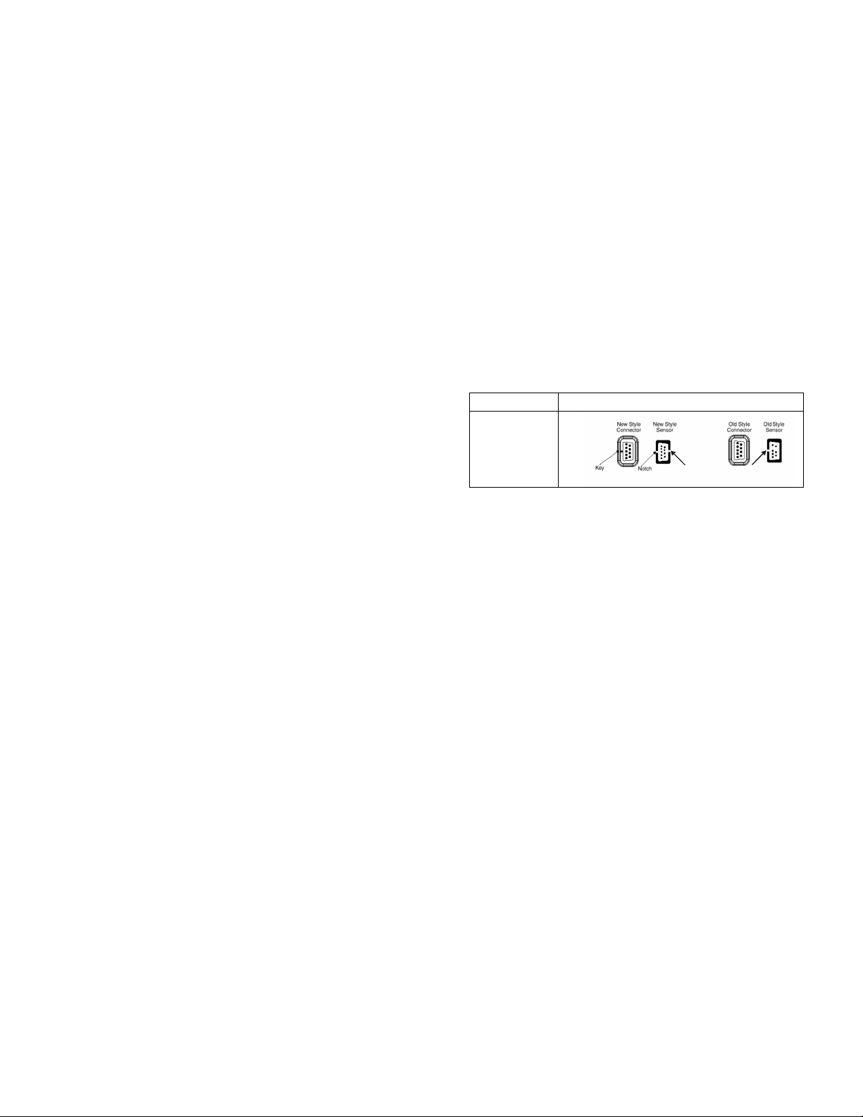
6.2 Connecting the SpO2 Fingerclip Sensor
The SpO
sensor to the patient, making sure it is in the correct orientation. Connect the sensor to the monitor. The
sensors come in sizes for adult and child. A range of sensors are available to attach to the patient’s
finger, toe, nose, forehead, or ear.
Fingerclip sensors – Pulse and oximetry are
measured from a fingerclip sensor. There are
several sizes of fingerclip sensors, and they
come in both reusable and disposable styles.
Sensors come in sizes for adults and children.
There are also sensors available that use the toes,
forehead, ear or nose as the measurement sites.
To obtain optimal performance, use an
appropriate sensor and apply it as described in
the sensor’s directions for use.
Connecting – Clip the sensor to the patient’s
finger. Make sure the cable to the sensor is
attached properly to the SpO
Warning: Do not place the fingerclip sensor on
Note: Avoid excessive ambient light, which can
Note: Prolonged use of the pulse oximetry probe
Note: If you fail to see any SpO
Note: Older style Nellcor™ sensors and extension cables
fingerclip sensor provides the means to take the oximetry and pulse readings. Clip the fingerclip
2
are not compatible with the connector on the
Nellcor™ option with motion tolerance, and must not
be plugged into it. However, new style Nellcor™
sensors and extension cables can be used with all
Nellcor options, and can be plugged into either the
old or new style connectors. The new style sensor
and connectors are illustrated below.
Cable Sensor
connector.
2
DEC-8
Performance factors –Many factors may
degrade the performance of the pulse oximeter,
an arm that is also being used for blood
pressure monitoring. Blood pressure cuff
inflation during SpO
cause inaccurate SpO
measurement will
2
results and false
2
alarms.
as indicated by a lowered rise of the
Plethysmograph display (next to SpO
These include:
• Excessive ambient light, particularly
fluorescent light.
• Excessive patient movement.
• Excessive duration on one finger.
affect sensor performance, by keeping the
fingerclip sensor and sensor site covered with
an opaque material.
• Cold hands/digits or hypothermia.
• Electrosurgical interference.
• Arterial catheters, blood pressure and fusion
lines.
may require you to change the location of the
probe. Move it to another finger every few
hours. Monitor skin condition and circulation
in the finger. Refer to the directions for use
provided with each sensor for specific
instructions on application and use.
• Moisture in the sensor.
• Improperly attached sensor.
• Incorrect sensor for the patient.
• Poor patient perfusion.
• Venous pulsations.
• Anemia or low hemoglobin concentrations.
• Cardiovascular dyes, such as methylene blue.
or
2
Plethysmograph readings, check that you
have properly inserted the sensor into the
Atlas monitor.
• Fingernail polish.
• Strongly pigmented skin.
•
Arterial occlusion proximal to the sensor.
Hypotension.
•
• Severe vasoconstriction.
• Cardiac arrest or shock
Notch Notch
display).
2
46
Page 59

Correct placement of reusable Nellcor SpO
fingerclip sensor
2
47
Page 60
6.3 Connecting the ECG Electrodes
Prepare the patient’s skin, attach the leads to the electrodes, place the electrodes in the three (or five)
correct locations, and plug the ECG cable into the monitor. The heart rate alarm usually operates in
conjunction with the ECG measurement.
Connecting - Connect the ECG leads to the
patient:
• Thoroughly clean the patient’s skin at each
place where an electrode will be attached.
Shave if necessary. Attach lead wires to the
electrodes before applying them to the
patient.
• Apply the electrodes to the patient as shown
in the diagrams for 3 wire and 5 wire
locations.
• Attach the ECG cable to the front panel
connector.
• Support the ECG cable so it does not stress
the electrode wires, the ECG cable
connectors, or electrodes. Ensure that
conductive parts of the electrodes and their
connectors do not contact any other
conductive parts, including earth.
• Verify that the monitor is configured for the
number of leads you are using.
You should now see an ECG waveform
•
scrolling across the upper part of the monitor
screen. If you do not, check the wires,
electrodes and cable.
3 wire or 5 wire - Either 3 wire or 5 wire ECG
leads can be used with the Atlas Monitor. You
must select either the 3 wire or 5 wire setting in
Advanced Configuration
are using. To change the lead set, press the
Date/Time button, then press Trend. The screen
will display the Advanced Configuration menu.
Scroll down to the ECG lead set selection using
Select button. Press the Set button to
either
choose 3 wire or 5 wire. After you make the
choice, press the
Advanced Configuration menu.
You can quickly determine whether the monitor
is set for 3 wire or 5 wire ECG: press the
button and watch the lead selection
Select
indicator in the upper right corner of the screen.
Trend button again to exit the
to match the leads you
Lead
• For 3 wire, Lead Select will cycle through I,
II, III
.
• For 5 wire,
II, III, aVR, aVL, aVF, V
Lead Select will cycle through I,
.
3 Wire Lead Colors & Symbols
Lead
Right arm White
Left arm Black
Left leg Red
AHA
RA
LA
LL
Red
Yellow
Green
5 Wire Lead Colors & Symbols
Lead
Right arm White
Left arm Black
Left leg Red
Right leg Green
Chest Brown V White
AHA
RA
LA
LL
RL
Red
Yellow
Green
Black
Interference factors - If an electrosurgical unit
is going to be used, place the ECG cable and
wires as far as possible from the site of the
surgery and from the electrosurgical cables. This
will minimize interference. Also ensure that the
electrosurgical return cable (neutral) is well
attached and making good contact with the
patient.
Impedance Respiration – In some patients,
impedance respiration detection may be
inadequate using the standard ECG electrode
placement. In these cases, change the LA and
RA electrode placement to the mid-axillary line
on each side of the chest as shown in the
illustration.
48
IEC
IEC
R
L
F
R
L
F
N
C
Page 61
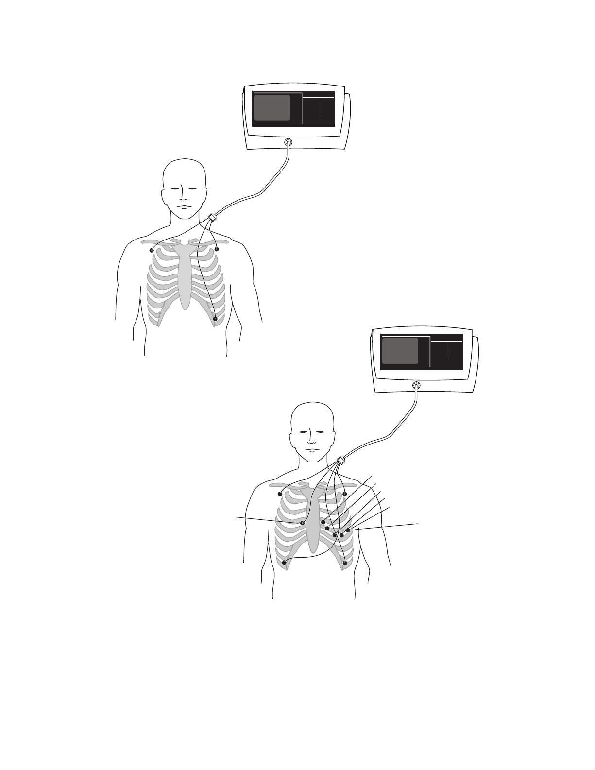
ECG
RA
LA
LLLL
ECG
V2
RA
V1
LA
V3
V4
V5
V6
One of six V Lead
electrode placement
sites for the fifth lead.
RL
LL
Correct placement of 3 wire and 5 wire ECG electrodes
49
Page 62

V-Lead Placement – The brown V-lead
connector can be placed at one of six standard
locations:
• V1 –Right Sternal border, fourth intercostal
space.
• V2 – Left sternal border, fourth intercostal
space.
• V3 –Between V2 and V4, midpoint between
the two, in a line that joins all three.
• V4 – Mid-clavicular line, fifth intercostal
space.
• V5 – Anterior axillary line, fifth intercostal
space.
• V6 – Mid-axillary line fifth intercostal
space.
Note: If you wish to see a cascading ECG
waveform from the upper line to the lower
line on the display, you must set the Second
trace source to ECG in the Advanced
Configuration menu.
50
Page 63
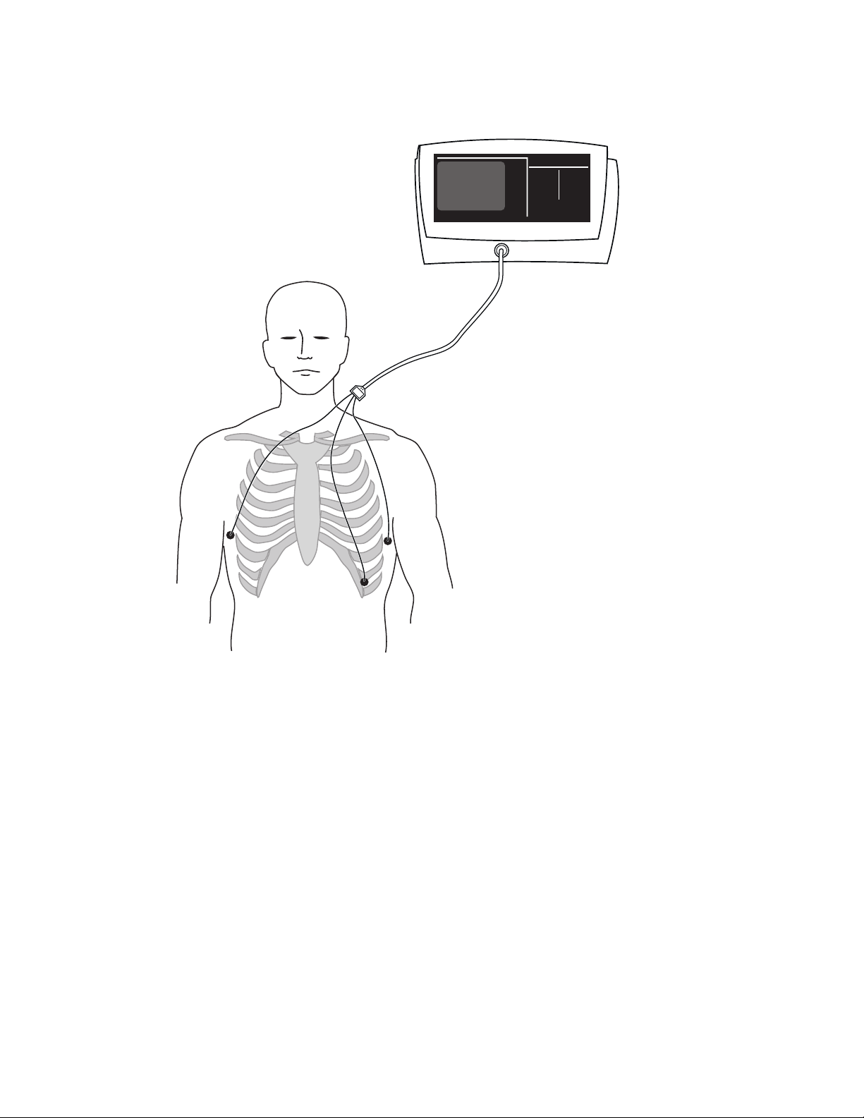
ECG
RA
LA
LLLL
Alternate ECG electrode placement for Impedance Respiration
51
Page 64

6.4 Connecting the Temperature Probe (Models 622xx & 623xx)
The Temperature measurement comes from a skin probe.
Atlas Monitor models 622xx and 623xx can
measure skin temperature with the supplied
surface probe. Follow the package instructions for
probe placement.
Fahrenheit or Celsius - Temperature is displayed
in °F or °C. The current setting is indicated next to
the temperature measurement.
You can change the Temperature units in
Advanced Configuration:
• Press the
• Press
Trend.
• Use either
Temperature units.
• Use either
and °C.
• Press
Trend to exit Advanced Configuration.
Date/Time button.
Select button to select
Set button to change between °F
No alarm - The temperature display is an
indicator only; there is no alarm for temperature.
If the monitor is unable to read a temperature
properly, dashes will appear in place of the
temperature measurement.
Note: The temperature display is blank at power-
up and will remain blank until a temperature
probe is detected.
52
Page 65

6.5 Connecting the End Tidal CO2 Sample Tube (Model 623xx)
ETCO
Attach the cannula to the patient’s nose. Connect the sample tube to the watertrap and plug the watertrap
into the monitor. – The watertrap should be replaced after (6) hours of use and discarded in accordance
with the institution’s infection control policies for disposables. An alarm sounds if the watertrap becomes
full.
End Tidal CO
with a cannula adapted for nasal use, and a
watertrap. These items are supplied with the
monitor. CO
medical supply vendors for direct connection to
ET tubes and LMAs.
Connecting the CO2 airway -
• Place the cannula below the patient’s nose so
• Direct the tubing along both cheeks and over
• Bring the tubing together beneath the patient’s
• Join the CO
• Plug the watertrap into the front panel of the
is measured with a sample tube using a nasal cannula adapted for sidestream CO2 measurement.
2
is collected through a sample tube
2
connectors are available from
2
Note: When ETCO
on the left and the CO
right above the CO
is displayed, the breath rate is
2
concentration is on the
2
waveform.
2
Watertrap – The watertrap should be replaced
after six (6) hours of use. The watertrap should be
discarded in accordance with the institution’s
infection control policies for disposables. If the
watertrap is full, an alarm will sound and a
that the tubes enter the nostrils.
the patient’s ears.
message reading “Replace CO
appear on the screen. The message “CO
watertrap occluded” may also appear. If this
watertrap” will
2
2
happens, change the watertrap.
chin and slide the plastic ring up to the chin for
a snug and comfortable fit.
watertrap to the sample line.
2
monitor at the connector for CO
analysis. Be
2
The watertrap should be handled as a biohazard
after use.
sure to push it in until it is firmly seated.
Correct placement of CO2 nasal cannula
53
Page 66

7 Using The Menus
Two menus are provided for configuring the Atlas Monitor. The items on these menus are choices that
you might make to configure the Atlas Monitor to your needs when you first place it into service. You may
change the date/time setting for Daylight Savings/Standard time, or when traveling across time zones.
You might change the Advanced Configuration settings when monitoring different patient health issues,
or for different display preferences.
7.1 The Set Date and Time and Other Options Menu
Pressing the
manage several settings. The Time and Date can be set using the
Options menu provides a list of buttons that have special functions.
Setting Date and Time - You will need to set the
Date and Time when:
• First unpacking and installing the monitor.
• Adjusting to different time zones.
• Starting or ending Daylight Savings Time.
To set the Date and Time:
• Press the
clock icon) to get to the Set Date and Time
menu.
• Use either Select button to sequentially
highlight the day, month, year, hours, minutes
and seconds.
• Use either
values for each setting.
• Stop pressing the
value is shown.
• Use either
highlight the next item you want to set, and
repeat.
• Press the
the waveform screen when the date and time
are correct.
The monitor now has the correct Time and Date,
and the monitor’s internal battery will retain these
settings, even after turning off the power and
unplugging the monitor.
Date/Time button on the bottom right of the monitor will access a menu from which you can
Select and Set buttons. The Other
Other Options menu - the buttons:
• Trend
• Lead Select
• Print (or Freeze)
• CO
/RESP ALARMS Off (model 623xx only)
2
which have been described earlier, serve a second
function, which is listed on this menu.
Date/Time button (labeled with a
Trend button accesses the Advanced
The
Configuration menu, which allows other settings
to be changed.
Lead Select button accesses the Service
The
Set button to scroll through the
Set button when the correct
Select button sequentially to
Mode screen, which allows a qualified technician
to service various aspects of the monitor.
Note: Service Mode is never used by the clinician
and is not to be used in any patient-oriented
operation of the monitor.
Print button (or Freeze in those monitors
Date/Time button again to return to
The
without a printer) saves the current alarm settings
as set by the user. These saved alarm settings are
used instead of the factory defaults when the
instrument is turned on.
CO2/RESP ALARMS Off button initiates the
The
process of CO
Reset.
2
Exiting the Set Date and Time Menu - To exit
the menu, press the
Date/Time button again.
54
Page 67

Set Date and Time
15 Jan 1999 19:18:50
Adjust using the Select and Set buttons
Press button to exit
Other Options
Press button
Trend
Adjust using the Select and Set buttons
Trend
Lead Select
Print
CO
/Resp Alarms
2
Lead Select Print
Alarm silence duration
ECG lead set
ECG sweep speed
ECG bandwidth
Initial cuff pressure
Monitor MAP
Second trace selection
Temperature units
Respiration sweep speed
Press the Trend button to exit
Advanced Configuration
Service Mode
automatic
Reset
Language
ECG gain
CO2 units
For
CO
2
English
60 seconds
automatic
5 wire
25mm/s
Monitor
160 mm/hg
Yes
CO
F
12.5 mm/s
mmHg
AC
2
Select
Select
PULSE
Off
Set
PULSE
Off
Set
Trend
Lead Select Print
AC
Atlas Monitor model 623xx showing the Advanced Configuration
and the Set Date and Time menus
55
Page 68

7.2 The Advanced Configuration Menu
The Advanced Configuration menu provides options to configure monitoring settings for your specific
needs. Access Advanced Configuration by pressing the
What’s it for? - This menu allows the user to
choose other options available with the monitor.
You may never need to change Advanced
Configuration settings. Most of the settings are
satisfactory for normal use as shipped from the
factory. Some users may make a few
adjustments when they first set up the monitor,
then may discover no further need to make
changes.
Advanced Configuration menu - To get to the
Advanced Configuration menu:
• Press the
the Set Date and Time and Other Options
menu.
• Press the
Advanced Configuration menu.
• Press either
Date/Time button. This will access
Trend button to enter the
Select button to highlight the
Date/Time button, then the Trend button.
parameter you want to change.
• Press either
you want for the parameter.
• Press either
parameter, or
• Press
the waveform display.
Advanced Configuration Details
lists all of the Advanced Configuration menu
items and the possible settings. Some of these
options may not appear on the monitor you are
using, depending on the model.
Set button to choose the value
Select to move on to the next
Trend to exit the menu and return to
- The table
56
Page 69

Advanced Configuration Menu Settings
Advanced Configuration Item
Possible settings
Factory
default
Language English, French, Canadian French,
Spanish, German, Portuguese, Italian,
Chinese, Japanese
Silence duration
ECG gain
ECG lead set
ECG speed
ECG bandwidth
Initial pressure
MAP
or
Alternate BP field (when language
setting is configured to Chinese only)
Second trace selection (621xx) ECG or SpO2 ECG
Second trace selection (622xx) ECG, SpO2 or Respiration ECG
Second trace selection (623xx) ECG, SpO2, Respiration or CO2 CO2
Temperature units (622xx and 623xx) ºF or ºC
Respiration speed (622xx and 623xx)
CO
units (623xx)
2
Print On Alarm (on models with
printers)
60, 90, or 120 seconds
automatic, or 10mm/mV
3 wire or 5 wire
6.25, 12.5, or 25 mm/s
Monitor or Extended
120, 140, 160, 180, 200, 240, 280 mmHg 160 mmHg
Yes or No
MAP, kPa, or nothing
12.5, 6.25, 3.125 mm/s 6.25 mm/s
mmHg, %, or kPa
Yes or No No
English
90 seconds
automatic
3 wire
25 mm/s
Monitor
No
ºF
mmHg
57
Page 70

7.2.1 Advanced Configuration Menu Settings
The Advanced Configuration menu offers settings to customize the Atlas Monitor to suit your needs. Not
all options are available on all models.
Language - Factory default will be set for the
dominant language used in your country. Of
course, if you are more familiar with another
language, the monitor provides a choice of eight.
Silence duration - The large
Silence button on
the right edge of the monitor allows you to turn
off all of the alarms simultaneously – for a short
duration lasting either 60, 90, or 120 seconds.
ECG gain - When 10 mm/mV gain is chosen,
the height of the vertical ruler that appears to the
left of the ECG waveform is 10 mm high and
indicates a 1 mV amplitude. When automatic
gain is selected the ruler height will vary, but it
will always indicate a 1 mV signal size. The ruler
size is automatically increased or decreased to
scale to a particular set of waves, but the vertical
line still indicates the same amplitude of 1 mV.
ECG lead set - The Atlas Monitor allows for
both 3 wire and 5 wire ECG lead sets.
ECG speed - The amount of ECG waveform
shown on the CRT is determined by the trace
speed. A slower trace speed means more
seconds of waveform are shown on the CRT.
ECG bandwidth - The ECG waveform can be
displayed and printed in either Monitor or
Extended bandwidth. Monitor mode allows for
a clearer picture of the waveform by filtering out
noise. Extended mode, usually used with
cardiac paced patients, shows the finer nuances
of ECG waveform facilitating the detection of
conditions such as ischemia.
Initial pressure – Specifies the initial blood
pressure cuff pump-up pressure. If this pressure
is not enough to complete a blood pressure
measurement, the cuff will re-inflate with a
higher target pressure and re-attempt the
measurement.
MAP - The Mean Arterial Pressure can be
displayed on the screen, above the ECG
waveform. This measurement is calculated from
the Systolic and Diastolic readings. The choices
are Yes (MAP is displayed) or No (MAP is not
displayed).
Alternate BP field (when language setting is
configured to Chinese only) – You can display
MAP or blood pressure in kPa on the screen
(upper left) above the ECG waveform. The
choices are MAP, kPa, or nothing. If you
choose “nothing” then, neither MAP nor kPa
will be displayed on the screen.
Second trace selection – All models offer a
choice of displaying a second line of ECG
waveform or displaying the SpO
waveform.
2
Model 622xx adds the option of displaying
Impedance Respiration as the second trace.
Model 623xx adds the option of displaying CO
concentration as the second trace.
Temperature units - In models 622xx and
623xx, temperature can be displayed as either
Celsius °C, or Fahrenheit °F.
Respiration speed – Models 622xx and 623xx
allow the Impedance Respiration or CO
2
waveforms to be displayed at three different
speeds.
2
58
Page 71

units – The concentration of Carbon Dioxide
CO
2
can be expressed in millimeters of mercury
(mmHg), percent (%), or kiloPascals (kPa). The
values displayed for percentage and kiloPascals are
calculated from the mmHg partial pressure based
upon current barometric conditions.
Print On Alarm - In models with printers, Print
On Alarm can be configured. If the
configuration is set to Yes, then a new Patient
Alarm or a new Measurement Invalid Alarm will
trigger an automatic print of the currently
configured waveforms and current
measurements. The alarming values will be
marked with asterisks in the printed report. A
Print On Alarm will not occur for low battery
alarms or for instrument problem alarms. If
alarms are silenced or suspended, a Print On
Alarm will not occur, but if the alarm is still
active when the silence period is over or when
the alarm is unsuspended, a Print On Alarm will
occur.
59
Page 72

8 Cleaning and Maintaining the Atlas Monitor
No harsh chemicals should be used for cleaning the monitor. A mild detergent solution works well. Care
should be taken to keep liquids away from the monitor and its connecting parts. Servicing should be
performed by a qualified technician at 6, 12, and 24-month intervals.
Cleaning – The Welch Allyn Atlas Monitor may
be wiped clean with a slightly damp cloth and a
mild detergent solution. Never immerse the
monitor in any type of liquid. As necessary, the
monitor may be cleaned with an appropriately
diluted, non-staining disinfectant solution.
Warning: Take care that no water or other
liquids enters any of the connectors. If this
should occur, dry them with warm air. Then
check all the monitoring functions to be sure
everything works properly.
Blood pressure cuff – The blood pressure cuff
should be cleaned by sponging with a damp
cloth.
Connections – Cables and hoses can be wiped
with a damp cloth and mild detergent. Do not
immerse the hoses or the cables.
Fingerclip sensor – The reusable SpO
fingerclip sensor may be cleaned with isopropyl
alcohol and may be sterilized with ethylene
oxide (EtO), cold cycle. Do not immerse the
sensor.
Temperature sensors – The temperature probes
and probe covers should be handled as biohazard
material after use and must be sterilized.
ETCO
watertrap – The watertrap should be
2
replaced after six (6) hours of use. The watertrap
should be replaced in accordance with the
2
institution’s infection control policies for
disposables. If the watertrap is full, an alarm will
sound and a message reading “Replace CO
2
watertrap” will appear on the screen. The
message “CO
watertrap occluded” may also
2
appear. If this happens, change the watertrap
The watertrap should be handled as a biohazard
after use.
Reset - The monitor keeps track of when
CO
2
the CO
subsystem was last reset. If the monitor
2
has been unused for a long time, is just being set
up, or if it has been more than one month since
its last reset, you may see a message on the
screen indicating that a CO
Reset is
2
recommended.
To perform a CO
• Press the
Reset:
2
Date/Time button on the lower
right of the monitor.
• The Set Date and Time and Other Options
menu will be displayed.
• Select the Reset CO
CO2/RESP ALARMS Off button.
the
• This will access a screen titled CO
selection by pressing
2
Reset.
2
• Follow the instructions on the screen.
• You will be told to remove the CO
2
watertrap
• You will be told to install the CO
Scrubber into the CO
watertrap socket.
2
2
The Scrubber looks similar to a
watertrap, but is filled with white
granules. It is included with model
623xx. The Scrubber must be attached to
the watertrap. Remove the tubing from
the watertrap and attach the Scrubber to
the watertrap. Insert the
watertrap/Scrubber combination into the
watertrap socket.
• There may be a message indicating a 5
minute Warming Up period.
60
Page 73

• The system will report that it is
Sampling.
• The system will then report Reset
Complete.
• Remove the watertrap/Scrubber from the
watertrap socket.
• Detach the Scrubber from the watertrap
and reattach the tubing.
• Replace the watertrap in the watertrap
socket.
• Press
Trend to return to the normal
screen.
Scrubber - The CO2 Scrubber has an
CO
2
indefinite lifespan when used at the normal rate
of one CO
reset every month and one CO2
2
calibration every 6 months. The Scrubber can be
disposed of as normal non-hazardous waste.
Servicing schedule – Servicing of the monitor
should be done at 6 month intervals by a
qualified service technician. It is important to
maintain this schedule to assure that the
measurements are accurate and that the unit is
working properly at all times. There are different
service requirements at 6, 12, and 24 month
periods, as documented in the Technical Service
Manual.
Battery Replacement (Models 622xx and
623xx) - If the monitor will not run for at least
an hour on battery after being plugged in to AC
for at least 24 hours, the battery may need to be
replaced. It is covered by warranty for the first
two years of ownership. If you are beyond the
warranty period, you can replace the battery by
the following method:
• Turn off the monitor and disconnect all
patient sensors
• Remove the AC power cord from the rear
of the monitor
• Using a TORX-10 screwdriver, remove
the two screws retaining the battery
cover
• Tip the monitor and slide the battery out
being careful not to stress the wires
• Press the locking clip release lever on the
plug that attaches the battery wires to the
Atlas and pull gently to remove the plug
from the Atlas
• Connect the replacement battery to the
connector in the Atlas. The plug can only
attach one way. The locking clip must
seat on the Atlas connector
• Slide the battery into the unit, routing the
wires around the edges of the battery and
being careful not to pinch the wires
• Replace the battery door and secure the
two screws
• Plug the Atlas back into AC power for at
least 24 hours to fully charge the battery
• You may return the Atlas to service (on
AC power) immediately
The battery is a non-spillable lead-acid battery.
In the USA, call 1-800-SAV-LEAD for
instructions on how to recycle. When the
internal lead-acid battery reaches the end of its
life, recycle the battery locally according
national, state, and local regulations. You can
also return the battery to Welch Allyn for
recycling.
61
Page 74

9 Unpacking and Installing the Atlas Monitor
When you first unpack the monitor, you should check it for shipping damage. Then verify that you have
all the accessories, documentation, and supplies.
Unpacking – As you carefully unpack the
monitor, inspect it for damage from shipping. If
you find any damage, notify the shipper
immediately. Save the packing material. It will
be useful if you have to return the monitor for
any reason. Next, remove the inner packing
material. Remove the plastic film that covers the
front panel.
Check the accessories - check all the
accessories against this list:
All models:
• 2 blood pressure cuffs.
• 1 SpO
fingerclip sensor with cable
2
• 1 power cord.
• 1 blood pressure hose.
• 1 ECG 3 wire lead set.
• 1 set of disposable ECG electrodes.
• (optional) 1 roll of printer paper.
• User manual.
Model 622xx: all the above plus:
• Temperature skin probe.
Model 623xx: all the above plus:
• 1 End Tidal CO
• 1 CO
• 1 CO
watertrap.
2
scrubber.
2
nasal cannula.
2
• 1 roll of printer paper.
Installing – The monitor can be installed and
used on a table top, shelf or other platform. This
surface should be level and stable. The Atlas
Monitor can optionally be mounted on a rigid
Welch Allyn custom mobile stand or wall
mount.
Warning: Do not use a standard hospital
mobile IV stand. The pole may tip over.
Warning: Keep the monitor away from liquids
that might spill on it.
Turn the Power On – When the monitor is
turned on, all alarms are enabled at the default
limits, and there is no trend data. If plugged into
AC power, an indicator AC~ shows the unit is
using AC power. The unit goes through an initial
self-check. When this is complete, the
instrument is ready to use.
Reset - On model 623xx, you may see a
CO
2
message indicating that a CO
reset is
2
recommended.
To perform a CO
• Press the
Reset:
2
Date/Time button on the lower
right of the monitor.
• The Set Date and Time and Other Options
menu will be displayed.
• Select the Reset CO
pressing the
CO2/RESP ALARMS Off
selection by
2
button.
• This will access a screen titled CO
Reset.
2
• Follow the instructions on the screen.
• You will be told to remove the CO
2
watertrap
• You will be told to install the CO
Scrubber into the CO
watertrap socket.
2
2
The Scrubber looks similar to a
watertrap, but is filled with white
granules. It is included with model
623xx. The Scrubber must be attached to
the watertrap. Remove the tubing from
the watertrap and attach the Scrubber to
the watertrap. Insert the
watertrap/Scrubber combination into the
watertrap socket.
• There may be a message indicating a 5-
minute Warming Up period.
62
Page 75

• The system will report that it is
Sampling.
• The system will then report Reset
Complete.
• Remove the watertrap/Scrubber from the
watertrap socket.
• Detach the Scrubber from the watertrap
and reattach the tubing.
• Replace the watertrap in the watertrap
socket.
• Press
Trend to return to the normal
screen.
63
Page 76

10 Appendix A: Technical Specifications for the Atlas Monitor
A.1 General Specifications:
Size 33 x 24 x 23 cm (13 x 9.5 x 8.75 inches)
Weight 4.3 kg (9.5 lb.) (model 621xx)
6 kg (13.2 lb.) (models 622xx & 623xx)
Display Type Cathode Ray Tube / LED
Display Size 275 x 125 mm (10.8 x 4.9 inches)
Screen Displays (numeric) Heart Rate (ECG)
MAP (mean arterial pressure)
BP in kPa (option for Chinese language setting
only)
Respiration Rate (impedance respiration, models
622xx and 623xx)
Respiration Rate (ETCO
CO
concentration (model 623xx only)
2
Screen Displays (waveform) ECG – one line, or cascading to two lines, with 1
mV scale bar on first line
SpO
2
Impedance Respiration (models 622xx and 623xx)
ETCO
(model 623xx)
2
Numeric Displays 3-digit green LED: Pulse
3 digit red LED: Systolic
3 digit red LED: Diastolic
2-digit red LED: SpO
4-digit green LED: Temperature (models 622xx
and 623xx)
Trend Data Date/Time, Heart Rate, Systolic, Diastolic, MAP,
SpO
2
Respiration Rate, Temperature (models 622xx and
623xx)
concentration (model 623xx)
CO
2
Trend Sampling Sample at every BP cycle, or every 15 minutes
Trend Capacity 144 samples, maximum time span 36 hours
Power Voltage 100 to 240 VAC
Power Frequency 50 - 60 Hz
Power Current 100 VA
Storage Temperature
-20° to 50° C
Storage Humidity 15 to 95% non-condensing
Storage Altitude -170 to 3050 meters
Operating Temperature
10° to 40° C
Operating Humidity 15 to 90% non-condensing
Operating Altitude -170 to 3050 meters
Type of Protection Against Electric Shock Class 1 (model 621xx)
Class 1, Internally powered (model 622xx, 623xx)
, model 623xx only)
2
%
2
64
Page 77

Degree of Protection Against Electric Shock Type CF: Defib Protected
Mode of Operation Continuous operation
Degree of Protection Against Harmful Ingress of
Water
Degree of Safety of Application in the Presence of
a Flammable Anesthetic
Medical Device Directive Classification II b
FDA Device Classification II
Canadian Medical Device Directive III
IPX2 (IEC 60529)
Equipment not suitable for use in the presence of a
Flammable Anesthetic Mixture.
A.2 SpO2 - Nellcor
SpO2 Range 40 to 100%
Measurement Method Functional saturation
SpO2 Accuracy
Nellcor (no motion)
Nellcor (with motion)
Pulse Range 20 to 250 beats/minute
Pulse Accuracy
Nellcor (no motion)
Nellcor (with motion)
Plethysmograph 10 segments, vertical bar graph; proportional to
Alarms Low SpO2
Alarm range SpO2: 60 to 99%
Audible signals (pulse tone) Frequency tracks SpO2 level
Audible volume (pulse tone) 8 levels including OFF
Update frequency – Nellcor Every heart beat
Sensor measurement wavelengths – Nellcor Red: 660 nm, nominal; Infrared: 890 nm, nominal
70 to 100%, (Specified at 28º to 42º C sensor
temperature)
± 2 digits
± 3 digits
± 3 digits at 20 to 250 bpm
± 5 digits at 55 to 125 bpm
pulse volume
High and Low Pulse Rate (if ECG not active)
Pulse Rate alarms use ECG Heart Rate settings
when ECG not used
Used alone, pulse tone tracks SpO
Used with ECG, pulse tone tracks ECG Heart Rate
pulse
2
65
Page 78

A.3 NIBP
Systolic Range 60 to 250 mmHg (8 to 33 kPa)
Diastolic Range 30 to 160 mmHg (4 to 21 kPa)
Mean Arterial Pressure (MAP) Range 40 to 190 mmHg
Blood Pressure Accuracy Per AAMI SP10-1992 Clause 4.4.2
Efficacy study results using Auscultatory Method
as Reference Standard are available upon request.
Heart Rate Range for Specified Accuracy 40 to 200 beats/minute
Display Numeric displays for Systolic, Diastolic and MAP
Cuff pressure displayed during measurement cycle
Data available in Trend display and printed report
Method Oscillometric
Control Manual and automatic control
Automatic Intervals 1, 3, 5, 10, 15, 30, and 60 minutes
Alarms High and Low Systolic
High and Low Diastolic
High and Low MAP (in mmHg)
Alarm Ranges Systolic Low Limits: 60 – 245 mmHg
Systolic High Limits: 65 – 250 mmHg
Diastolic Low Limits: 30 – 150 mmHg
Diastolic High Limits: 35 – 155 mmHg
MAP Low Limits: 45 – 185 mmHg
MAP High Limits 50 – 190 mmHg
Initial Cuff Pressure 120, 140, 160, 180, 200, 240, 280 mmHg - user
selectable
Repeated Cuff Pressure Previous Systolic pressure + 40 mmHg
Maximum Inflation Time 3 minutes (typical: <40 seconds)
Inflation Over-Pressure Dump <300 mmHg
Inflation Over-Pressure Dump Backup <330 mmHg
A.4 ECG
Heart Rate Range 21 to 249 beats/minute
Heart Rate Accuracy
Bandwidth, Normal Mode 0.5 to 40 Hz
Bandwidth, Extended Mode 0.05 to 100 Hz
Leads 3 wire or 5 wire, available in AHA or IEC colors
Connector AAMI 6 pin
Electrodes Disposable snap electrodes
Display Sweep Speeds 6.25, 12.5, 25 mm/second
Gain 10 mm/mV, and automatic gain with visual scale
±3 beats/minute or ±3% whichever is greater
indicator
66
Page 79

Scale Reference Bar A fixed 1 mV reference bar is displayed with the
top ECG waveform for scaling of the waveform.
This is provided in place of a standardizing voltage.
Lead Display Single, user selectable: I, II, III; or I, II, III, aVR,
aVL, aVF, V
Heart Rate Display Numeric
Waveform Display One or two rows (cascading) of ECG waveform
display
Leads Off Condition Detected and displayed (selected lead only)
Alarms High and Low Heart Rate
Alarm Ranges Heart Rate Low Limits: 21 to 245 beats/minute
Heart Rate High Limits: 25 to 249 beats/minute
Pulse Tone Constant frequency, ECG used alone;
Synchronized to SpO
pulse tone, ECG and SpO2
2
used together, frequency varies with perfusion
Input Impedance >2.5 Megohms at 10Hz
Input Protection Defibrillator and Electrosurgery protected
Defibrillator Recovery per EC13:1992 Clause
<8 seconds
3.1.2.1a)
Impedance Respiration/Leads Off Detection
Current per EC13:1992 Clause 3.1.2.1b)
Tall T Wave Rejection per EC13:1992 Clause
50nA max for RA ,LA, LL, V; 200nA max for RL
Rejects Tall T waves through 1.4 mV
3.1.2.1c)
Heart Rate Averaging Method per EC13:1992
Clause 3.1.2.1d)
Number of consecutively detected beats:
>12: Heart rate = 60/(average of last 12 detected
consecutive R-R intervals)
<12: Heart rate = 60/(average of the detected
consecutive R-R intervals)
Response to Change in Heart Rate per EC13:1992
Clause 3.1.2.1f)
Time to Alarm for Tachycardia per EC13:1992
Clause 3.1.2.1g)
Increasing from 80 to 120 beats/minute: 3 sec
Decreasing from 80 to 40 beats/minute: 9 sec
Waveform 4(a)
Amplitude: Average time to alarm:
0.5 mV 6.21 seconds
1.0 mV 50.2 seconds
2.0 mV 10.96 seconds
Waveform 4(b)
Amplitude: Average time to alarm:
1.0 mV 50.3 seconds
2.0 mV 12.06 seconds
4.0 mV 6.40 seconds
Pacemaker Display per EC13:1992 Clause 3.2.9.12 Pacemaker signals displayed as captured.
67
Page 80

Pacemaker Rejection per EC13:1992 Clause 3.1.4.1 Rejects all specified pacemaker signals, including
double paces, without over/undershoot.
Exception: Ineffectively paced QRS pattern may
cause a QRS to be rejected and not counted as a
pulse when the pace occurs very close to the R
wave.
Pacemaker Rejection per EC13:1992 Clause 3.1.4.2 Rejects all specified pacemaker signals, including
double paces, with over/undershoot with the
exception of ±2 mV amplitude, 0.1 ms duration, 0.5
mV overshoot, time constant=100
A.5 Printer (standard Model 623xx, optional Models 621xx & 622xx)
Printing method Direct thermal
Printer type Thermal array
Resolution Vertical: 8 dots/mm (203 dots/inch)
horizontal: 12 dots/mm (305 dots/inch)
Printing speed 25 mm/second
Chart position accuracy (dot to dot)
Effective print width 54 mm ± 0.2 mm
Paper capacity 100 foot roll of 58 mm paper, non printed grid
Paper loading non-threading, drop-in from top of unit
Time scale 25 mm/second
Printout data Waveform: 15 second record of ECG; lead
Print timing Waveforms: 9 seconds prior to PRINT button
±5%
selected, gain setting, time scale
Waveform: 15 second record of selected second
waveform
Numeric: Systolic, Diastolic, MAP, ETCO
Respiration Rate, Temperature, Time and Date (as
configured)
press, 6 seconds after button press
Numeric data captured at time of button press
,
2
A.6 Impedance Respiration (Models 622xx & 623xx)
Measurement Technique Trans-thoracic impedance
Leads RA to LA (Lead I)
Current 50 nA max
68
Page 81

Range 5 to 100 breaths/minute
Accuracy
Alarms High and Low Respiration Rate
Alarm Ranges Respiration Low limits: 5 to 99 breaths/minute
Waveform Display One line Respiration waveform
Respiration Rate Display Numeric
Display Sweep Speeds 3.125, 6.25, 12.5 mm/second
±3 breaths/minute
Respiration High limits: 6 to 100 breaths/minute
A.7 Temperature (Models 622xx & 623xx)
Range 17° to 50°C (62.6° to 122° F)
Accuracy ±0.2°F, ±0.1°C plus probe tolerance.
Resolution ±0.1°F or ±0.1°C
Compatibility YSI 400 series probes
Alarms None provided
Temperature Display Numeric
Units Fahrenheit or Centigrade
A.8 Backup Battery (Models 622xx & 623xx)
Type Sealed Lead Acid (leak proof)
Duration BP reading every 5 minutes; 15 second strip printed
every 5 minutes:
1 hour (model 622xx)
45 minutes (model 623xx)
Charging Automatic when AC power connected
Charge time 80% capacity: 5 hours
100% capacity: 24 hours
Alarms Low battery
Very low battery
Nearly depleted battery
Low Battery Alarm 10 minutes remaining; chime every 2 minutes and
CRT message
Very Low Battery Alarm 5 minutes remaining; chime every minute and CRT
message
Nearly depleted Battery Alarm 1 minute remaining; trend data printed; continuous
alarm and CRT message; system shut down, BP
pressure released
69
Page 82

A.9 I/O Communications (Models 622xx & 623xx)
Connector RJ45 socket on rear of case
Nurse Call Signal Normally open relay contacts between pins #1 and
#8 of RJ45 connector. Contacts closed when any
alarm is audible.
Normally closed relay contacts between pins #2
and #8 of RJ45 connector. Contacts open when any
alarm is audible. Contacts rated for 1 A, 240 VAC.
Serial Interface Bi-directional RS232; 9600 baud, 8 bit, 1 stop bit,
no parity, no flow control
Protocols Pangea SIO command interface
Welch Allyn serial communications protocol
A.10 End Tidal CO2 (Model 623xx)
Measurement Method Sidestream
Measurement Range 0 to 98 mmHg
Percentage and kPa conversions are based on
current barometric pressure.
Measurement Accuracy Ambient temperature 15ºC to 45ºC:
0 to 40 mmHg: ±3 mmHg;
41 to76mmHg: ±8% of reading;
77 to 99 mmHg: ±10% of reading.
Ambient temperature 5ºC to 15ºC and 45ºC to
55ºC:
0 to 40 mmHg: ±4 mmHg;
41 to76mmHg: ±10% of reading;
77 to 99 mmHg: ±12% of reading.
Accuracy unspecified for breath rates >30
breaths/minute.
Standard Conditions Automatic compensation to comply with BTPS.
BTPS CO
Breath Rate Range 5 to 100 breaths/minute
Breath Rate Accuracy
Display Units mmHg, %, kPa; user selectable
Resolution 1 mmHg
Alarms High and Low CO2 measurement
±1 breath/minute or ±5%, whichever is greater
High and Low Respiration Rate
= (internal measurement) x 1.03
2
70
Page 83

Alarm Ranges Low CO2 Limits: 0 to 97 mmHg
High CO
Limits: 1 to 98 mmHg
2
Low Respiration Limits: 5 to 99 breaths/minute
High Respiration Limits: 6 to 100 breaths/minute
Display Sweep Speed 3.125, 6.25, 12.5 mm/second
Start-up Time <10 seconds to acquire waveform; <5 minutes to
full operating specifications
Display Waveform, Respiration Rate and CO2 measurement
displayed on CRT and printer
Interfering Gas Compensation:
Nitrous Oxide or Oxygen Concentration Greater
than 50%
No automatic compensation provided, user must
apply equations provided.
O2 concentration >50%, no N2O:
Actual CO
= (displayed measurement) x 1.03
2
O concentration >50%:
N
2
Actual CO
= (displayed measurement) x 0.952
2
Stability Unaffected by humidity or temperature within
specified operating range; unaffected by moisture
in sampled air
Rise Time 0.58 second rise time; 0.59 second fall time
Delay Time 5.4 seconds
Total System Response Time 5.99 seconds
Sound Pressure Without tubing: 50.2 dB
With tubing: 48 dB
Diversion Flow Nominal 175 ml/minute
Adverse Effects of Testing per ISO 9918:1992
System remains within specification
Clauses 50, 60, 61, 62; EN864:1997 Clauses 50,
101, 102, 103
Adverse Effects of Electrocautery, Electrosurgery,
Defibrillation, X-ray, IR, Conducted Transients,
Magnetic Fields, RFI
Clinical Utility within 8 seconds of electrosurgery
and defibrillation;
Not suitable for use in MRI
71
Page 84

11 Appendix B: Electromagnetic Compatibility (EMC)
The Atlas monitor has been tested and found in compliance with the requirements of IEC 60601-12:1993.
This Welch Allyn Atlas Monitor is suitable for use in the specified electromagnetic environment. The
buyer or user of this product should assure that it is used in an electromagnetic environment as
specified below:
Emissions Category EMC Environment
CISPR 11
(Radiated and
Conducted)
Harmonics IEC1000-3-2
Voltage
Fluctuations/Flicker
Immunity Severity Level EMC Environment
ESD 3 Floors are wood, concrete, ceramic or are covered
Radiated RF 2
Conducted RF 2
EFT 2 Mains power quality is that of a typical commercial
Surge 3 Mains power quality is that of a typical commercial
Voltage
Dips/Interrupts
Magnetic Field 2 Magnetic fields are at levels typical in a commercial
Group 1, Class B
IEC 1000-3-3
3 Mains power quality is that of a typical commercial
This product is suitable for use in domestic
establishments and in establishments directly
connected to the low voltage power supply network
that supplies buildings used for domestic purposes.
with synthetic material. Relative humidity must be
greater than 15%.
Portable communication devices may interfere with
the proper operation of this device. Warnings should
be posted to prevent these devices from coming near
the monitor during operation. If the monitor is placed
near a stationary RF transmitter and the performance
of the monitor is questioned, either remove the
transmitter or monitor then document the change in
performance from the monitor. A site survey may be
required to determine if excessive RF energy could
pose a problem for monitor operation.
and hospital environment.
and hospital environment.
and hospital environment. If CLINICAL UTILITY is
required during power interruptions, it is
recommended that the unit be operated from an
uninterruptible power supply.
and hospital environment.
72
Page 85

12 Appendix C: Calibration and Maintenance
The Atlas Monitor must be serviced by authorized Welch Allyn personnel or agents at 6 month intervals.
Maintenance requirements are specified for 6 month, 12 month and 24 month service intervals. The
monthly CO
Reset operation can be performed by the user.
2
Service Interval Maintenance Requirements
Every month CO2 Reset
Every 6 months CO2 Calibration
Button test
LED test
Printer test
Every 12 months All 6 month maintenance requirements
BP Calibration
ECG Calibration
Battery test
Every 24 months All 6 month maintenance requirements
All 12 month maintenance requirements
ECG signal gain & noise test
Temperature measurement check with calibrated probe
measurement check and functional tests
SpO
2
73
Page 86

13 Appendix D: Accessories for the Welch Allyn Atlas Monitor
Part number
Blood Pressure Accessories
5200-01 Adult Cuff Assembly (cuff, latex-free bladder and connectors)
5200-02 Large Adult Cuff Assembly (cuff, latex-free bladder and connectors)
5200-03 Small Cuff Assembly (cuff, latex-free bladder and connectors)
5200-10 Extra-large Cuff Assembly (cuff, latex-free bladder and connectors)
5200-04 Adult Bladder (latex-free, includes connector)
5200-05 Large Adult Bladder (latex-free, includes connector)
5200-06 Small Bladder (latex-free, includes connector)
5200-11 Extra-large Adult Bladder (latex-free, includes connector)
5082-59 Adult Cuff
5082-61 Large Adult Cuff
5082-63 Small Cuff
5082-64 Extra-large Adult Cuff
5082-204-3 Child size durable, one piece cuff (includes connectors)
5082-205-3 Small adult size durable, one piece cuff (includes connectors)
5082-206-3 Adult size durable, one piece cuff (includes connectors)
5082-207-3 Large Adult size durable, one piece cuff (includes connectors)
5082-208-3 Extra-large adult size durable, one piece cuff (includes connectors)
5200-19 Straight Pressure Hose (5 feet, latex-free)
5200-12 Straight Pressure Hose (8 feet, latex-free)
5200-08 Calibration "T" Connector
Nellcor Puritan Bennett Pulse Oximetry Accessories
DS-100A DURASENSOR Adult Oxygen Transducer
DEC-8 Extension Cable (8 feet)
D-YS DURA-Y Oxygen Transducer (1 sensor, 40 wraps)
D-YSE Ear Clip (use with Dura-Y sensor)
D-YSPD PediCheck Pediatric Spot Check (use with Dura-Y sensor)
MAX-A OxiMAX Adult (single use, case of 24)
MAX-AL OxiMAX Adult, long cable (single use, case of 24)
MAX-P OxiMAX Pediatric (single use, case of 24)
MAX-R OxiMAX Adult Nasal (case of 24)
MAX-FAST OxiMAX Adult Forehead (case)
OXICLIQ A Adult Oxygen Transducer, use with OC-3 cable
OXICLIQ P Pediatric Oxygen Transducer, use with OC-3 cable
OC-3 OxiCliq Sensor Cable
OXI - A/N
OXI - P/I OXIBAND Pediatric/Infant Transducer (1 sensor, 50 wraps)
SRC-MAX Portable Oximetry Tester
Description
OXIBAND™ Adult/Neonatal Transducer (1 sensor, 50 wraps)
74
Page 87

Power Cord Accessories
5200-110 Line Cord (US / Canada / Japan version)
5200-111 Line Cord (European version)
5200-112 Line Cord (United Kingdom version)
5200-113 Line Cord (Australian version)
5200-114 Line Cord (Swiss version)
5200-115 Line Cord (South American version)
Mounting Accessories
6200-30 Mobile Stand
6200-31 Wall Mount
Miscellaneous Accessory Items
6200-40 Printer Paper – Case (25 rolls)
6200-41 Replacement battery
6200-42E Operator Manual (English version)
6200-42F Operator Manual (French version)
6200-42G Operator Manual (German version)
6200-42S Operator Manual (Spanish version)
6200-42I Operator Manual (Italian version)
6200-42P Operator Manual (Portuguese version)
6200-42C Operator Manual (Chinese version)
6200-42J Operator Manual (Japanese version)
6200-44 Inservice Training Videotape (English, NTSC version)
6200-43E Technical Service Manual (English)
6200-45 Monitor Carrying Case
Thermometry Accessories
6200-15 Temperature Probe-Surface
ECG Accessories
6200-01 ECG Patient Cable (3 lead AHA)
6200-02 ECG Patient Cable (5 lead AHA)
6200-03 ECG Patient Cable (3 lead IEC)
6200-04 ECG Patient Cable (5 lead IEC)
6200-05 ECG Leads, 3 Lead (AHA)
6200-06 ECG Leads, 5 Lead (AHA)
6200-07 ECG Leads, 3 Lead (IEC)
6200-08 ECG Leads, 5 Lead (IEC)
6200-09 Disposable Electrodes (package of 3)
6200-10 Disposable Electrodes (package of 5)
6200-11 Disposable Electrodes (package of 30)
6200-12 ECG Wrist-Klip
6200-71 ECG Cable with attached leads (3 lead AHA)
6200-72 ECG Cable with attached leads (5 lead AHA)
6200-73 ECG Cable with attached leads (3 lead IEC)
6200-74 ECG Cable with attached leads (5 lead IEC)
75
Page 88

ETCO2 Accessories
6200-20 ETCO2 Water Trap (package of 5)
6200-21 ETCO2 Scrubber
6200-22 ETCO2 Adult Nasal Sample Line
6200-23 ETCO2 Adult Nasal Sample Line (package of 10)
6200-24 ETCO2 Sample Line
6200-25 ETCO2 Divided Cannula (ETCO2 sample line plus O2 delivery)
6200-120 ETCO2 Dryer Sampling Line with TEE for High Humidity Circuits (package of 25)
6200-121 ETCO2 Dryer Sampling Line for High Humidity Circuits (package of 25)
6200-122 ETCO2 Dryer Sampling Line with TEE for Low Humidity Circuits (package of 25)
6200-123 ETCO2 Dryer Sampling Line for Low Humidity Circuits (package of 25)
6200-124 Adult O2 Delivery / ETCO2 Nasal Sampling Line (Soft) (package of 25)
6200-125 Adult O2 Delivery / ETCO2 Nasal Sampling Line (Molded) (package of 25)
6200-126 Adult ETCO2 Nasal Sampling Line (Soft) (package of 25)
6200-127 Pediatric ETCO2 Nasal Sampling Line (Soft) (package of 25)
6200-128 Pediatric O2 Delivery / ETCO2 Nasal Sampling Line (Soft) (package of 25)
6200-129 Adult/Pediatric ETCO2 Sampling Tee (package of 50)
76
Page 89

14 Appendix E: Troubleshooting
E.1 Diagnosing Atlas Monitor Problems
E.1.1 Blood Pressure
PROBLEM:
Blood pressure readings are inaccurate.
RECOMMENDED ACTIONS:
Squeeze all air out of cuff and repeat measurement.
Check the cuff for correct size for the patient – check that the index mark falls within the range markings.
Check the cuff for proper fit – there should be room to insert no more than two fingers between the
deflated cuff and the patient’s limb. A cuff applied too loosely may result in artificially high readings.
Check the cuff for proper alignment – there is a mark indicating where the cuff should align over the
patient’s brachial artery.
Check the patient:
The blood pressure should be taken on a bare arm.
Place patient with midpoint of upper arm at heart level. This is approximately at the mid-axillary
line at the 4
Have patient lie down.
Patient must be motionless. Excess movement, shivering, seizure could interfere with the
measurement.
If the patient is sitting, the back and legs should be supported. The lower arm should be passively
supported. i.e. sitting in patient’s lap.
Unusual physiology, obesity, or poor circulation could be preventing Atlas Monitor from
detecting the pulse.
Cardiac arrhythmia could interfere with the measurement.
Have the unit recalibrated.
PROBLEM:
Blood pressure cannot complete reading in 3 minutes.
RECOMMENDED ACTIONS:
Safety mechanisms automatically abort blood pressure measurements when a reading has not been
obtained within 3 minutes;
Check for leaks in tubing and cuff, and at connections.
Check the cuff for correct size for the patient – check that the index mark falls within the range markings.
Check the cuff for proper alignment – there is a mark indicating where the cuff should align over the
patient’s artery.
Check the patient:
Must be motionless. Excess movement, shivering, seizure could interfere with the measurement.
Unusual physiology, obesity, or poor circulation could be preventing Atlas Monitor from
detecting the pulse.
Cardiac arrhythmia could interfere with the measurement.
Set Initial pressure higher if many repressurization steps are necessary due to high patient blood
pressure.
th
intercostal space.
77
Page 90

PROBLEM:
Blood pressure automatic timing stops.
RECOMMENDED ACTIONS:
Safety mechanisms automatically stop the timed blood pressure measurements when the Atlas Monitor
repeatedly fails to make a measurement within 3 minutes
;
Determine the reason that the measurements are failing and restart the timed cycle. Press BP
Start/Cancel
to manually start a measurement; Auto timing will resume.
E.1.2 CO2
PROBLEM:
Pump does not start.
RECOMMENDED ACTIONS:
Watertrap not fully inserted.
CO
not selected as Second trace selection in Advanced Configuration menu.
2
PROBLEM:
Display does not start - waveform, Respiration Rate, CO
RECOMMENDED ACTIONS:
Watertrap not fully inserted.
not selected as Second trace selection in Advanced Configuration menu.
CO
2
PROBLEM:
Long delay in starting/stabilizing waveform display or numeric displays.
RECOMMENDED ACTIONS:
function is specified to begin display within 10 seconds, but not to reach full specification for up to 5
CO
2
minutes.
Restriction in sampling tubing.
Poor placement of nasal cannula in patient’s nose.
Patient breathing orally.
Patient breathing very shallowly.
PROBLEM:
readings inaccurate.
CO
2
RECOMMENDED ACTIONS:
Pressure or suction being applied to sampling tubing – check for flow interference from ventilation,
oxygen, anesthetic supplies.
High concentration of oxygen or nitrous oxide requires compensation calculation – see section
A.10 End Tidal CO2 (Model 623xx).
Poor placement of nasal cannula in patient’s nose.
not displayed.
2
78
Page 91

Patient breathing orally.
Patient breathing very shallowly.
exhaust port on rear of unit blocked or obstructed.
CO
2
Have the unit recalibrated.
PROBLEM:
pump sounds change – speeding up, slowing down.
CO
2
RECOMMENDED ACTIONS:
Flow restrictions or leaks in tubing.
exhaust port on rear of unit blocked or obstructed.
CO
2
E.1.3 Displays
PROBLEM:
CRT display is misaligned, twisted, or tilted.
RECOMMENDED ACTIONS:
Have CRT mounting adjusted by Service.
PROBLEM:
Extraneous marks on CRT display – extra lines, overlapping numbers.
RECOMMENDED ACTIONS:
Turn the power off and back on; this will clear the display.
PROBLEM:
An LED segment/display is not functioning.
RECOMMENDED ACTIONS:
Have unit repaired.
E.1.4 ECG
PROBLEM:
ECG waveform baseline is drifting on screen.
RECOMMENDED ACTIONS:
Change ECG Bandwidth from Extended to Monitor in Advanced Configuration menu.
Check connections:
ECG trunk cable at Atlas Monitor socket.
ECG leads at trunk cable.
ECG leads at electrodes.
Check for proper placement of electrodes on patient.
Check for good contact of electrodes to patient – shave, clean if necessary.
Minimize patient motion.
79
Page 92

PROBLEM:
Heart Rate is not being displayed by ECG.
RECOMMENDED ACTIONS:
If ECG waveform is displayed:
Wait 20 seconds for heart rate to be determined and displayed.
Select different leads for display (wait 20 seconds after selecting). Some leads may sense QRS
complexes that have too low of an amplitude for the Heart Rate detection circuit.
Evaluate ECG waveform – excess noise, low QRS amplitude, arrhythmia could interfere with
determining stable heart rate.
If ECG waveform is not displayed:
Check connections:
ECG trunk cable at Atlas Monitor socket.
ECG leads at trunk cable.
ECG leads at electrodes.
Check for proper placement of electrodes on patient.
Check for good contact of electrodes to patient – shave, clean if necessary.
PROBLEM:
ECG waveform is noisy or erratic.
RECOMMENDED ACTIONS:
Change ECG Bandwidth from Extended to Monitor in Advanced Configuration menu.
Change ECG Gain to Automatic in Advanced Configuration menu.
If using a 3 wire lead set, ensure that ECG lead set is set to 3 wire in Advanced Configuration menu.
Check connections:
ECG trunk cable at Atlas Monitor socket.
ECG leads at trunk cable.
ECG leads at electrodes.
Check for proper placement of electrodes on patient.
Check for good contact of electrodes to patient – shave, clean if necessary.
Eliminate patient movement.
Move ECG cables away from other equipment and possible interference sources.
Evaluate interference sources:
Models 622xx, 623xx – unplug AC and run on battery power to determine whether interference is
from power line.
Move RFI sources and radio transmitters away from Atlas.
Turn off fluorescent lights.
PROBLEM:
ECG Leads Off fault not reported.
RECOMMENDED ACTIONS:
ECG Leads Off is only detected and reported on the Lead that is currently being monitored.
80
Page 93

PROBLEM:
ECG waveform, heart rate corrupted by Electrosurgery or Electrocautery.
RECOMMENDED ACTIONS:
Monitor is specified to return to Clinical Utility within 8 seconds of discontinuance of electrosurgery;
Heart Rate display may require up to 20 seconds to stabilize.
Verify that electrosurgery neutral (return) line is making good contact with patient.
Route ECG cables as far as possible from electrosurgery site and neutral line.
PROBLEM:
ECG Heart Rate significantly differs from SpO
pulse rate.
2
RECOMMENDED ACTIONS:
ECG heart rate may be inaccurate due to arrhythmia, cabling problems.
SpO2 pulse rate may be inaccurate due to poor perfusion, poor blood flow to limb, light interfering with
sensor, patient movement.
Manually measure pulse by
arterial palpation to determine which instrument is reading incorrectly and
troubleshoot that instrument further.
PROBLEM:
Pacemaker signals not visible on ECG trace.
RECOMMENDED ACTIONS:
Pacemaker signals are displayed as captured; the Atlas Monitor does not have an option to present
symbolic indication of pacemaker signals;
Change ECG Bandwidth to Extended in Advanced Configuration menu.
Change ECG Gain to Automatic in Advanced Configuration menu.
PROBLEM:
Heart Rate inaccurate on pacemaker patient.
RECOMMENDED ACTIONS:
Certain unusual artifacts of pacemaker signals may be counted as pulse signals. Connect SpO
sensor and
2
monitor displayed Pulse rate as an adjunct measurement.
In patients with pacemakers that are not successfully capturing the pulse, certain timing interactions
between pace signal and pulse can cause an occasional additional pulse beat to be counted.
E.1.5 Impedance Respiration
PROBLEM:
Cannot detect impedance respiration.
RECOMMENDED ACTIONS:
Move leads to mid-axillary positions as shown in Connecting the ECG Electrodes.
Check connections:
ECG trunk cable at Atlas Monitor socket.
ECG leads at trunk cable.
ECG leads at electrodes.
81
Page 94

Check for good contact of electrodes to patient – shave, clean if necessary.
PROBLEM:
Impedance respiration waveforms are not displayed immediately.
RECOMMENDED ACTIONS:
Some impedance respiration signals will cause a delay of up to two minutes to properly display the
waveform. This time is required as the Atlas Monitor adapts to the specific signals and centers the
waveform on the screen.
E.1.6 Power
PROBLEM:
AC~ indicator not lit.
RECOMMENDED ACTIONS:
Atlas Monitor is specified to operate on any voltage from 100 to 240, and on 50 or 60 Hz – verify that the
service provided meets these requirements;
Check proper connection of AC cord in Atlas Monitor appliance socket.
Check proper connection of AC cord in wall outlet.
Check proper power cord for local outlet standards.
Check for tripped fuse or circuit breaker in AC service.
If no problems are found, have the unit repaired.
PROBLEM:
Atlas Monitor turns itself off without warning.
RECOMMENDED ACTIONS:
Atlas Monitor is designed to turn itself off if the battery is depleted (goes below 5 volts).
During normal usage, the “Battery depleted – shutdown imminent” warning message will appear before
the Atlas Monitor turns itself off.
Plug the Atlas Monitor into AC and allow the battery to charge for a few minutes before using the
instrument on AC.
If this problem occurs while you are using the Atlas Monitor and not at startup, it indicates that the battery
is likely defective or damaged.
The battery must be repaired/replaced.
You can still operate the Atlas Monitor on AC power if available.
PROBLEM:
Battery life is too short.
RECOMMENDED ACTIONS:
Model 622xx is specified for 1 hour of battery life when operating ECG, SpO
pressure, with one blood pressure measurement every 5 minutes, and one printout every 30 minutes;
Model 623xx is specified for 45 minutes of battery life when operating ECG, SpO
and blood pressure with one blood pressure measurement every 5 minutes, and one printout every 30
minutes;
Battery charge time is specified as 24 hours to full charge, 5 hours to 80% charge;
Battery charging occurs whenever unit is plugged in to AC power, whether it is operating or not;
The Atlas monitor should be plugged into AC power unless being used on a short-term transport.
, Temperature, and blood
2
, Temperature, CO2,
2
82
Page 95

Reduce the frequency of blood pressure measurements or printouts if practical.
Charge Atlas for 24 hours and time battery life in use as specified above; if less than the specified battery
life is provided, the battery must be replaced.
E.1.7 Printer
PROBLEM:
Printer does not print
RECOMMENDED ACTIONS:
If paper is not feeding out of printer:
Check that paper is installed with end of paper extending beyond door slot.
Check that printer door is closed.
Check for paper scraps jamming in roller and gears in printer door.
Have unit repaired.
If paper is feeding out of printer, but it is blank:
Check that thermal side of paper faces the front of the Atlas Monitor.
Replace paper with a new roll (preferably with a known good partial roll).
Check that the printer door is fully closed and latched.
Have unit repaired.
PROBLEM:
Printing too light / too dark.
RECOMMENDED ACTIONS:
Replace paper with a new roll.
Have unit repaired.
PROBLEM:
Printing blurred.
RECOMMENDED ACTIONS:
Check that printer door is properly closed.
Replace paper with a new roll.
Have unit repaired.
PROBLEM:
Printer keeps printing without stopping (or without stopping for long).
RECOMMENDED ACTIONS:
If Print On Alarm is configured and a physiological value is near the alarm limit, multiple Print On Alarm
prints could be triggered in a row as the physiological value moves over the limit and then back into the
normal range again and again. This appears like continuous printing. Adjust the alarm limit so that the
current physiological value does not keep tripping the alarm, or change the Print On alarm setting to No
in the Advanced Configuration screen.
83
Page 96

E.1.8 Sounds
PROBLEM:
Pulse or alarm sounds are too loud or too quiet when unit is turned on.
RECOMMENDED ACTIONS:
Sound levels can be changed and then set as default values – see section: Managing the Alarms
PROBLEM:
No pulse tone.
RECOMMENDED ACTIONS:
Check default volume setting for pulse tone – see section: Managing the Alarms.
Press SpO
volume up button several times.
2
If SpO
is not active and ECG is active:
2
Pulse tone will not sound until a stable Heart Rate is measured and displayed by ECG – this can
take up to 20 seconds;
If Heart Rate is displayed, have unit repaired.
If SpO
is active and ECG is active:
2
Pulse tone will not sound until a stable heart rate is measured and displayed by ECG – this can
take up to 20 seconds;
If Heart Rate is displayed, have unit repaired.
If SpO
is active and ECG is not active:
2
If Pulse measurement is displayed, have unit repaired.
E.1.9 SpO
2
PROBLEM:
No SpO
reading or plethysmograph display.
2
RECOMMENDED ACTIONS:
Check that the sensor is properly installed in the Atlas monitor.
Check connection of SpO
sensor to extension cable.
2
Check patient: see section Connecting the SpO2 Fingerclip Sensor
E.1.10 Temperature
PROBLEM:
Temperature display is blank
RECOMMENDED ACTIONS:
No temperature probe has been detected: check connection at Atlas Monitor front panel.
84
Page 97

PROBLEM:
Temperature display is inaccurate
RECOMMENDED ACTIONS:
Skin probe:
Verify proper placement on patient.
Eliminate drafts or other airflow near probe – cover with tape.
Oral, rectal, skin probe:
Replace probe.
Have unit repaired.
E.2 Atlas Monitor Error Messages
MESSAGE:
Altitude too high - CO2 unavailable
Altitude too low - CO
MEANING:
The ambient barometric pressure is too high or low for Atlas Monitor ETCO
RECOMMENDED ACTIONS:
If you are not above 1700 meters, or below 170 meters below sea level, this indicates a failure or
calibration error in the Atlas Monitor barometric sensing system. The unit must be repaired.
MESSAGE:
unavailable
2
functions.
2
Battery depleted - shutdown imminent
MEANING:
The battery (models 622xx and 623xx) is drained. The system will shut down within one minute.
RECOMMENDED ACTIONS:
If you have AC power available, plug in the Atlas Monitor. The battery will recharge automatically,
whether the Atlas Monitor is turned on or off. The battery will return to 80% charge within 5 hours, and
full charge within 24 hours. You will see the
When operating on battery power, you can extend the battery life by reducing the number of Blood
Pressure measurements and printouts.
MESSAGE:
AC~ symbol lit above the ECG cable connection.
Battery is missing
MEANING:
The Atlas Monitor cannot detect the battery (models 622xx and 623xx). It has been removed, or there has
been a failure of the battery or its connections.
RECOMMENDED ACTIONS:
The battery must be replaced.
You can still operate the Atlas Monitor on AC power if available.
85
Page 98

MESSAGE:
Blood pressure failure, service required
MEANING:
Atlas Monitor has detected a malfunction of the Blood Pressure system.
RECOMMENDED ACTIONS:
A mechanical or electrical fault has been detected in the Blood Pressure system. Remove the Atlas
Monitor from service. The unit must be repaired.
MESSAGE:
Check blood pressure cuff
MEANING:
The Atlas Monitor has detected a problem in making a Blood Pressure measurement. No internal problem
is detected. Either the Atlas Monitor could not detect a pulse, could not bring the cuff to the required
pressure, or detected an overpressure condition. There may also be a problem that prevented the Atlas
Monitor from completing a measurement within 3 minutes of the start of the measurement.
RECOMMENDED ACTIONS:
Check the tubing for kinks, crimps, or constrictions.
Check the tubing for leaks at the Atlas Monitor connection, and at the cuff connection.
Check the cuff for leaks.
Check the cuff for correct size for the patient – check that the index mark falls within the range markings.
Check the cuff for proper fit – there should be room to insert two fingers between the deflated cuff and
the patient’s limb.
Check the cuff for proper alignment – there is a mark indicating where the cuff should align over the
patient’s brachial artery.
Check the patient – must be motionless. Excess movement, shivering, seizure could interfere with the
measurement.
Check the patient – unusual physiology, obesity, or poor circulation could be preventing Atlas Monitor
from detecting the pulse.
MESSAGE:
Clock battery is dead - service required
MEANING:
There is a lithium battery inside the Atlas Monitor model 621xx that runs the time-of-day clock. It has
lost power and the Atlas Monitor is no longer able to maintain its time settings. In models 622xx and
623xx, the rechargeable battery runs the clock, and it is depleted.
RECOMMENDED ACTIONS:
The model 621xx lithium battery must be replaced. The models 622xx and 623xx batteries can be
recharged by plugging the system into AC power for 5 to 24 hours.
MESSAGE:
Clock not set
MEANING:
The time-of-day clock and calendar has not been set.
86
Page 99

RECOMMENDED ACTIONS:
Press the
Date/Time button to access the Set Date and Time menu. Use the Select and Set buttons to set
the correct date and time.
MESSAGE:
CO2 cannula or hose occluded
MEANING:
The CO
system has detected a flow restriction in its intake.
2
RECOMMENDED ACTIONS:
Check the tubing for kinks, bends, or blockage.
Check the patient’s nasal cannula for blockage.
Replace the watertrap.
MESSAGE:
CO2 failure, service required
MEANING:
The Atlas Monitor has detected a malfunction of the CO
system.
2
RECOMMENDED ACTIONS:
A mechanical or electrical fault has been detected in the CO
system. Remove the Atlas Monitor from
2
service. The unit must be repaired.
MESSAGE:
CO2 Reset Failed
MEANING:
When performing a CO
Reset operation, the Atlas Monitor samples CO2-free air through the Scrubber, to
2
use as a baseline reference. This reset operation has failed.
RECOMMENDED ACTIONS:
Turn the Atlas Monitor off and back on, and retry the CO
Reset operation. Repeat several times if
2
necessary. If repeated attempts fail, then the unit must be repaired.
MESSAGE:
CO2 reset recommended
MEANING:
The Atlas Monitor has determined that the baseline (no CO
CO
Reset procedure. The Atlas Monitor will recommend a CO2 Reset operation about once per month.
2
RECOMMENDED ACTIONS:
At a convenient time, perform a CO
623xx. The CO
system is safe to use in the interim before you perform the reset.
2
Reset procedure using the CO2 Scrubber included with your model
2
) setting should be verified by performing a
2
87
Page 100

MESSAGE:
CO2 watertrap not detected
MEANING:
The Atlas Monitor has CO
selected as the Second trace selection, has been monitoring CO2, and can
2
now no longer detect the watertrap. This message will not occur unless the Atlas Monitor has been
successfully monitoring CO
and has subsequently lost contact with the watertrap.
2
RECOMMENDED ACTIONS:
Check to see that the watertrap is firmly inserted in its socket. You will hear the CO
pump start when the
2
watertrap is properly inserted.
If the CO
pump does not start when the watertrap is inserted, there is a failure in the circuitry that detects
2
the watertrap. The unit must be repaired.
MESSAGE:
Configuration lost - Factory default settings are active
MEANING:
A problem has occurred with the internal memory of the Atlas Monitor. The Patient Alarm settings that
were saved have been lost, and the Patient Alarms are set back to the factory default settings. Advanced
Configuration settings and volume settings may also have been reset to factory defaults.
RECOMMENDED ACTIONS:
Change the alarm limit settings and volume settings back to your preferences. Check the Advanced
Configuration menu settings and change them to your preferences. Save your settings. Return to the
waveform screen, and turn off the power. Turn the power back on. Your settings should remain, and you
should not see the error message again. It is now safe to return the Atlas Monitor to use.
If you see the error message again when you turn on the power, it indicates an internal problem with the
Atlas Monitor. The unit must be removed from service and repaired.
MESSAGE:
ECG failure, service required
MEANING:
The Atlas Monitor has detected a malfunction of the ECG system.
RECOMMENDED ACTIONS:
An electrical fault has been detected in the ECG system. Remove the Atlas Monitor from service. The
unit must be repaired.
MESSAGE:
ECG lead fault
MEANING:
Atlas Monitor has detected a problem with the ECG leads. A signal cannot be properly detected.
Note that Atlas Monitor only reports lead faults on the lead that is currently selected by the Lead Select
button (and indicated in the upper right corner of the screen).
RECOMMENDED ACTIONS:
Check the ECG cable connection on the front of the Atlas Monitor.
Check the connections of the individual ECG leads where they attach to the ECG trunk cable. Verify that
the correct leads are plugged into the correct sockets. Make sure that you are not confusing AHA and IEC
lead color schemes.
88
 Loading...