

Page 1
Patient Monitor
Operator Manual
Welch Allyn Medical Division
Page 2

oNtraPveR
noitpircseD#NCEetaDdevorppA
E34-0026A
launaM
ecivreSSALTAfoesaeleRweN
92404-599/01PL/SR
Drawings and/or illustrations and/or part numbers contained in this document
are for reference purposes only. For current revisions call the Welch Allyn
Customer Service phone number listed in Section 1 page 2.
SERVICE MANUAL 6200-43E REV. A
WELCH ALLYN ATLAS PATIENT MONITOR i
Page 3

Contents PAGE
Section 1: General Information
1.1 About the Atlas ............................................................................................................ 1
1.2 T echnical Help Information, W orldwide T ech Support Phone Number........................... 2
1.3 Product Model Number Structure ................................................................................. 3
1.4 Main Menu Architecture ................................................................................................ 6
1.5 Atlas System Block Diagram ........................................................................................ 7
Section 2: Service (See User Manual 6200-42E for Atlas Specifications)
2.1 Incoming Inspection,Checklist ...................................................................................... 1
2.2 Repair Tests ............................................................................................................. 2-4
Table 2-1 :Tools Required for Service, Calibration and Software Loading ................... 5
Table 2-2:Software/Firmware Revision Levels ............................................................ 6
2.3 Calibration Procedures
BP Calibration - Section 2.3.1 ........................................................................... 7
ETCO2 Calibration (623Models only) - Section 2.3.2.........................................7&8
CO2 Reset (623Models only) - Section 2.3.3 ........................................................ 9
Printer Calibration - Section 2.3.4 ....................................................................... 10
Battery V oltage Calibration (Models 622xx and 623xx only)- Section 2.3.5 .... 10&11
T emperature Measurement Subsystem Calibration- Section 2.3.6 ...................... 12
Set Battery Charge V oltage-Section 2.3.7 .......................................................... 13
2.4 Software
Software Chart#2.4 .1.......................................................................................... 14
Downloading Operating System 2.4.................................................................... 15
2.5 Downloading NVRAM T ext files ............................................................................ 15&16
2.6 Downloading Software and NVRAM T ext files............................................................. 16
2.7 Product Numbering Structure .................................................................................... 17
Section 3: Troubleshooting (Also see Atlas Operator’s manual Appendix E)
3.1 Functional T ests/ Initial Diagnostic Steps ...................................................................... 1
3.2 T echnical T roubleshooting T ables: Complaint/Cause/Corrective Action ....................... 12
3.3 T op Level T roubleshooting Index .................................................................................. 15
3.4 Diagnostic T ests and Test Setups ............................................................................... 17
Section 4: Disassembly and Repair
About Section 4 .................................................................................................................... 1
4.1 Model 200 Dissassembly .............................................................................................. 2
4.2 Model 200 Re-assembly.............................................................................................. 13
4.3 Other Models notes ..................................................................................................... 15
ii WELCH ALL YN A TLAS P ATIENT MONITOR
SERVICE MANUAL 6200-43E REV. A
Page 4

Appendix Section:
A...............................................................................................................theory of operations
B...................................................................................................................... repair parts list
C....................................................................................interconnect diagram 620396 Rev A
D...................................................................... electrical schematics and circuit board layouts
E...........................Safety T ests: Required Equipment and Procedures and Test Results Form
SERVICE MANUAL 6200-43E REV. A
WELCH ALLYN ATLAS PATIENT MONITOR iii
Page 5

Section 1 - General Information
The Atlas combines in one unit all the necessary measurements for patients under anesthesia, for surgical
recovery , or bed side monitoring. See Section 1.3 for a
complete listing of product models and options.
According to the standards of care for Nurse Anesthetists and Anesthesiologists, all patients receiving conscious sedation are to be continuously monitored
throughout the procedure and recovery phase by ECG,
SpO2, and NIBP. CO2 monitoring is a requirement during gas anesthesia (when patient is ventilated).
The Atlas combines a CRT to display ECG and CO
waveforms and LEDs for the other numeric values to
maximize visibility and viewing angle. Although not
designed to be a transport product, the monitor has an
integral handle and it is small and light enough at 13 lb
to be easily moved. A one hour battery enables the
monitor to be moved with the patient from the surgery
room to recovery room. It also maintains unit operation
for up to an hour when power is interrupted.
1.1 About the Atlas Monitor
2
IMPORT ANT: for a complete description on the function and use of the Atlas, as well as user safety warnings, cautions, and warranty information, read and
understand the Atlas Operator’s Manual part number
6200-42E (English). Other languages are available.
SERVICE MANUAL 6200-43E REV. A
WELCH ALLYN ATLAS PATIENT MONITOR 1
Page 6

Section 1 - General Information
1.2
Help Information
Safety Warnings
All service and repairs must be performed by fully trained
and properly equipped personnel, using genuine
replacement parts and correct procedures. Failure to do
so will invalidate the product warranty.
Read and understand all safety warnings and
service notes printed in this Service Manual and the
Operator’s Manual part number 6200-42E. If in
doubt about any precaution or procedure, for
phone help, or to order additional copies of the
Atlas Operator’s Manual, contact:
Customer Service
Welch Allyn, Inc.
4341 State Street Road, PO Box 220
Skaneatles Falls, NY 13153-0220 U.S.A
Telephone 1-800-535-6663
When calling, refer to the model number on the
bottom of the Atlas. The Model Number is the first three
digits of the Serial number number found on the bottom
of the Atlas.
Treat all returned opened Nasal CO2 Sample Lines
and watertraps as Bio Hazard material and dispose
of them in an approved manner.
Troubleshooting assistance is contained in Section 3 of
this manual to help determine which board is
malfunctioning. This manual does not support repairing
the printed circuit boards.
Year 2000 Information: The Atlas is Y2K compliant and
will not encounter “Year 2000” problems.
2 WELCH ALL YN A TLAS P ATIENT MONITOR
SERVICE MANUAL 6200-43E REV . A
Page 7

Section 1 - General Information
1.3 Product Model Number Structure
621S0 ECG, Nonin SpO2, NIBP
621SP ECG, Nonin SpO2, NIBP , Printer
622S0 ECG, Nonin SpO2, NIBP, T emp, Respiration, Battery , RS232
622SP ECG, Nonin SpO2 , NIBP, T emp, Respiration, Battery , RS232, Printer
622N0 ECG, Nellcor SpO2, NIBP , Temp, Respiration, Battery , RS232
622NP ECG, Nellcor SpO2, NIBP, T emp, Respiration, Battery , RS232, Printer
623SP ECG, Nonin SpO2, NIBP, ETCO2, T emp, Respiration, Battery , RS232, Printer
623NP ECG, Nellcor SpO2, NIBP, ETCO2, T emp, Respiration, Battery , RS232, Printer
SUFFIX:
Use letter designation for language localization as follows:
E = English, F= French, G= German, I= Italian, S= Spanish, P= Portuguese C = Chinese,
J= Japanese
Use number designation for line cord localization as follows:
1 = US, Canada, Japan V ersion
2 = European Version
4 = United Kingdom Version
6 = Australian V ersion
SERVICE MANUAL 6200-43E REV A WELCH ALLYN ATLAS PATIENT MONITOR 3
Page 8
Section 1 - General Information
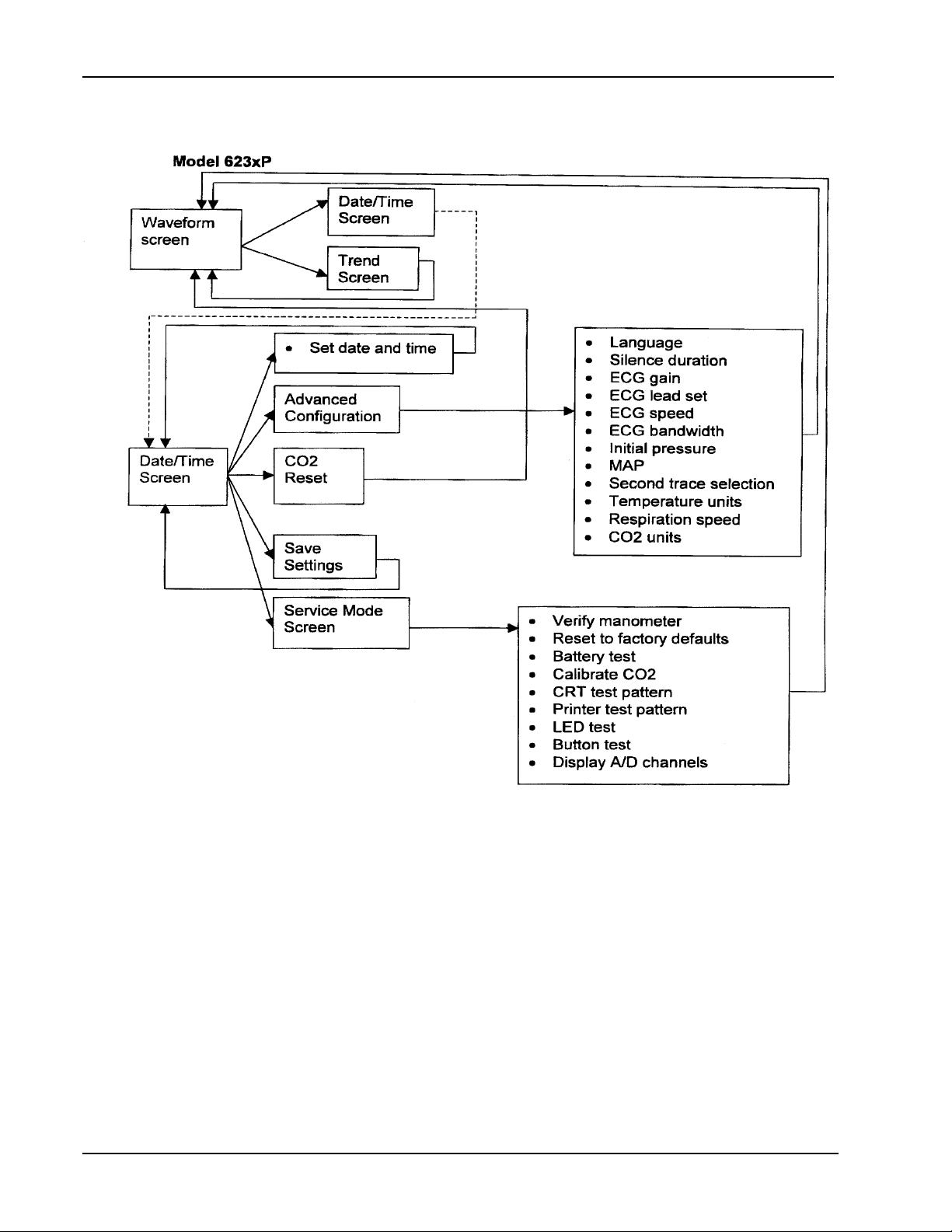
1.4 Main Menu Architecture
*
Also note that this is for the 623xx system.
• On a 622xP system, delete the CO2 Reset box, the Calibrate CO2 item, and the CO
units item.
• On a 621xP system, delete the CO2 Reset box, the Calibrate CO2 item, the CO
units item, Respiration speed item, the T emperature units item, and the Battery
test item.
• On systems without printers (621x0 and 622x0) delete the Printer test pattern item.
*
The Display A/D Channels also lets you press <SET> up and down to display additional
sets of information, but does not change the menu page that you are on, just writes
different information on the right side of the screen.
4 WELCH ALL YN A TLAS P A TIENT MONITOR SERVICE MANUAL 6200-43E REV A
2
2
Page 9
Section 1 - General Information
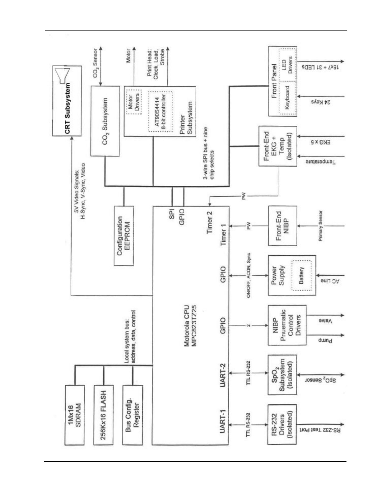
Section 1.5 Atlas System Block Diagram
SERVICE MANUAL 6200-43E REV A WELCH ALLYN ATLAS PATIENT MONITOR 5
Page 10

Section 2 - Service
o 2.1.1 Inspect shipping package and product
for damage. Make a record of possible
shipping damage.
2.1.2 List accessories in box.
o power cord
o SpO2 probe
o ECG leads
o ECG lead cable
o Cuff(s)
o Operator Manual
o nasal C02 Line
o ECG Electrode(s)
o temperature probe
o BP tubing
o paper
o loose parts, describe
2.1 Incoming Inspection
Service Intervals for
Calibration and Maintenance are listed in
Atlas Operator’s
Manual Appendix C.
o 2.1.3 Clean and disinfect by following the
instructions printed in the Operator
Manual.
o 2.1.4 Operate the Atlas to verify the customer
complaint before making any changes to
the unit. Call the customer if the complaint
is unclear .
NOTE: Perform REPAIR TESTS in
Section 2.2 to fully inspect the
Atlas monitor before and after
servicing. Refer to Section 3
for Troubleshooting help.
2.1.5 If the unit has caused or is suspected of
having caused an injury of any type:
DO NOT DISASSEMBLE OR REP AIR
THE UN IT IN ANY WA Y.
Contact Welch Allyn Customer Service
immediately .
SERVICE MANUAL 6200-43E REV . A WELCH ALLYN ATLAS MONITOR 1
Page 11

Section 2 - Service
2.2 Repair Tests 2.2.1 Blood Pressure System Leakage T est:
BP Leak Test
Unit must not leak more than 5 mmHg in a 15
second interval while attached to a 100 cc
volume at test pressures of 50mmHg and
250mmHg.
Need:
100cc (+10/-0cc) test cavity
stopwatch
squeeze bulb
2.2.1.1 Connect Atlas to test 100cc volume and
Setra Gage as shown in Figure 2.3.1.1
2.2.1.2 Turn Atlas ON
2.2.1.3 Press Time and Date button to access
Options Menu.
2.2.1.4Press Lead Select button to select
Service Mode. Select V erify Manometer
2.2.1.5Pressurize the Atlas with squeeze bulb
to 50mmHg.
NOTE: Allow reading to stabilize for 15 seconds.
2.2.1.6Observe pressure for 15 additional
seconds. Unit should not leak more than
5mmHg during this time.
2.2.1.7Perform this process at 250mmHg
BP Dump Test
Manometer Accuracy Test
2.2.2 Dump T est:
Unit must be able to deflate a 500 cc volume
from greater than 260.0 mmHg to less than
15.0 mmHg in 10 seconds or less.
2.2.3 Manometer Accuracy T est
Internal temperature of the unit must be less
than 32.0 degrees Celsius before performing
test.
2.2.3.1 The primary transducer must be within +/-
0.75 mmHg at 0 +/-0.3 mmHg. The safety
transducer must be within +/-1 mmHg at
0+/-0.3 mmHg.
2.2.3.2 The primary transducer must be within +/-
1.5 mmHg at 50 +/-5.0 mmHg. The safety
transducer must be within +/-1.5 mmHg at
50 +/- 5.0 mmHg.
2.2.3.3 The primary transducer must be within +/-
1.5 mmHg at 150 +/-5.0 mmHg. The
safety transducer must be within +/-4.5
mmHg at 150 +/- 5.0 mmHg.
2.2.3.4 The primary transducer must be within +/-
2 WELCH ALL YN A TLAS MONITOR
SERVICE MANUAL 6200-43E REV. A
Page 12

Section 2 - Service
2.2.4 Deflation T est:
With the unit connected to a large adult cuff
and a target inflation pressure of 200 mmHg*
have the unit perform a complete “normal”
BP cycle.
For steps two and three, the size of the step
must be between 3.0 mmHg and 1 1.0 mmHg.
Step 4 and all other steps above or equal to
40 mmHg, step size must be between 7.0
mmH gand 1 1.0 mmHg. All steps below 40
mmHg, except for the last step, will be
between 4.5 mmHg and 10 mmHg. The last
step will be between 0.01 mmHg and 10
mmHg.
2.2.5 Charge Voltage Test:
Check battery charging circuit:
Specification :No Load: 6.85VDC across
right pin (+) and left pin (-) of Main PCB
battery charge connector .
Deflation T est
* Go to service mode
screen and set initial
pressure to 200mmHg.
Charge Voltage Test
2.2.6 Hardware Fail Safe Tests
2.2.6.1 Over Pressure T est:
Atlas hardware must detect over
pressure on unit pneumatic system
between 296.0 mmHg and 329.0 mmHg.
2.2.6.2 Over 15 mmHg T est:
Atlas hardware must detect if the
pneumatic system has been pressurized
greater than 15 mmHg for more than 155
seconds but less than 180 seconds.
2.2.6.3 Under 15 mmHg Test:
Atlas hardware must detect if the
pneumatic system has been pressurized
less than 15 mmHg for more than 25.0
seconds but less than 35.0 seconds
before alowing new inflation cycle in “nonStat” Auto Mode.
2.2.7 RS232 T est:
The RS232 communication operation
will be confirmed with successful
serial transmit and receive.
Hardware Fail Safe Tests
RS232 Test
2.2.8 Printer Option T est:
Printer Option T est
The printer must be able to print out the test
pattern . Inspect print quality .
SERVICE MANUAL 6200-43E REV . A WELCH ALLYN ATLAS MONITOR 3
Page 13

Section 2 - Service
ECG Test
NOTE:
Section 3 of this Service
Manual contains
troubleshooting steps for
the ECG subsystem.
These tests will help
determine if the main
board is faulty .
2.2.9 ECG T est:
Use a calibrated simulator to check
performance.
NOTE: There is no calibration for the ECG or
impedance Respiration subsystems.
If the performance does not match up to that
expected using a calibrated simulator then
there could be a problem with the cable, leads,
connectors, wiring or the main board itself. If
the main board is faulty then replace it.
SpO2 T est
NOTE:There is no
calibration for the SpO2 and
Pulse subsystem. If the
performance does not
match up to that expected
using a calibrated simulator,
or the Phantom finger set,
then the subsystem board
must be replaced.
2.2.10SpO2 T ests:
Need:
Appropriate Phantom finger set
SpO2 cuff and cable
Or:
Nellcor or Nonin (as fitted) simulator
(replaces cuff to drive subsystem)
Or:
Calibrated SpO2 simulator that has a cuff
fitting that simulates a perfused finger
Nonin: Settings for NoninPatient Simulator
8000S are 98% O2 / 80 BPM. SpO2 board
accuracy after 25 second stabilization period
must be within +/-2%O2 and +/- 2BPM.
Nellcor: Settings for Nellcor Patient Simulator
SRC-2 are 81% O2 and 112 BPM. SpO2 board
accuracy after 25 second stabilization period
must be within +/-2% O2 and +/- 2 BPM.
Temperature Test
4 WELCH ALL YN A TLAS MONITOR
2.2.1 1TEMP ACCURACY VERIFICA TION
Need:
Calibrated thermometer (DIGIT AL OR GLASS)
small insulated container with cover for warm water
2.2.1 1.1Fill container wtih approximately 96 degree
F water
2.2.1 1.2Attach temperature probe neaqr the sensing
part of the thermometer and insert into the
warm water .
2.2.1 1.3Accuracy must be within +/- 0.2 degrees F.
SERVICE MANUAL 6200-43E REV. A
Page 14
Page 15

Section 2 - Service
T able 2-2:Software/Firmware revision levels
LEDOMmetsySgnitarepOredaoltooBroclleNninoNnoyrP
OS12699/8/9,0004.10.AA99/02/6,0000.10.AA7V
PS12699/8/9,0004.10.AA99/02/6,0000.10.AA7V
OS22699/8/9,0004.10.AA99/02/6,0000.10.AA7V
PS22699/8/9,0004.10.AA99/02/6,0000.10.AA7V
ON22699/8/9,0004.10.AA99/02/6,0000.10.AA79/71/210.0.2.1V
PN22699/8/9,0004.10.AA99/02/6,0000.10.AA79/71/210.0.2.1V
PS32699/8/9,0004.10.AA99/02/6,0000.10.AA7V00.1VE.0
PN32699/8/9,0004.10.AA99/02/6,0000.10.AA79/71/210.0.2.1V00.1VE.0
6 WELCH ALLYN ATLAS MONITO R SERVICE MANUAL 6200-43E REV. A
Page 16
Section 2 - Service
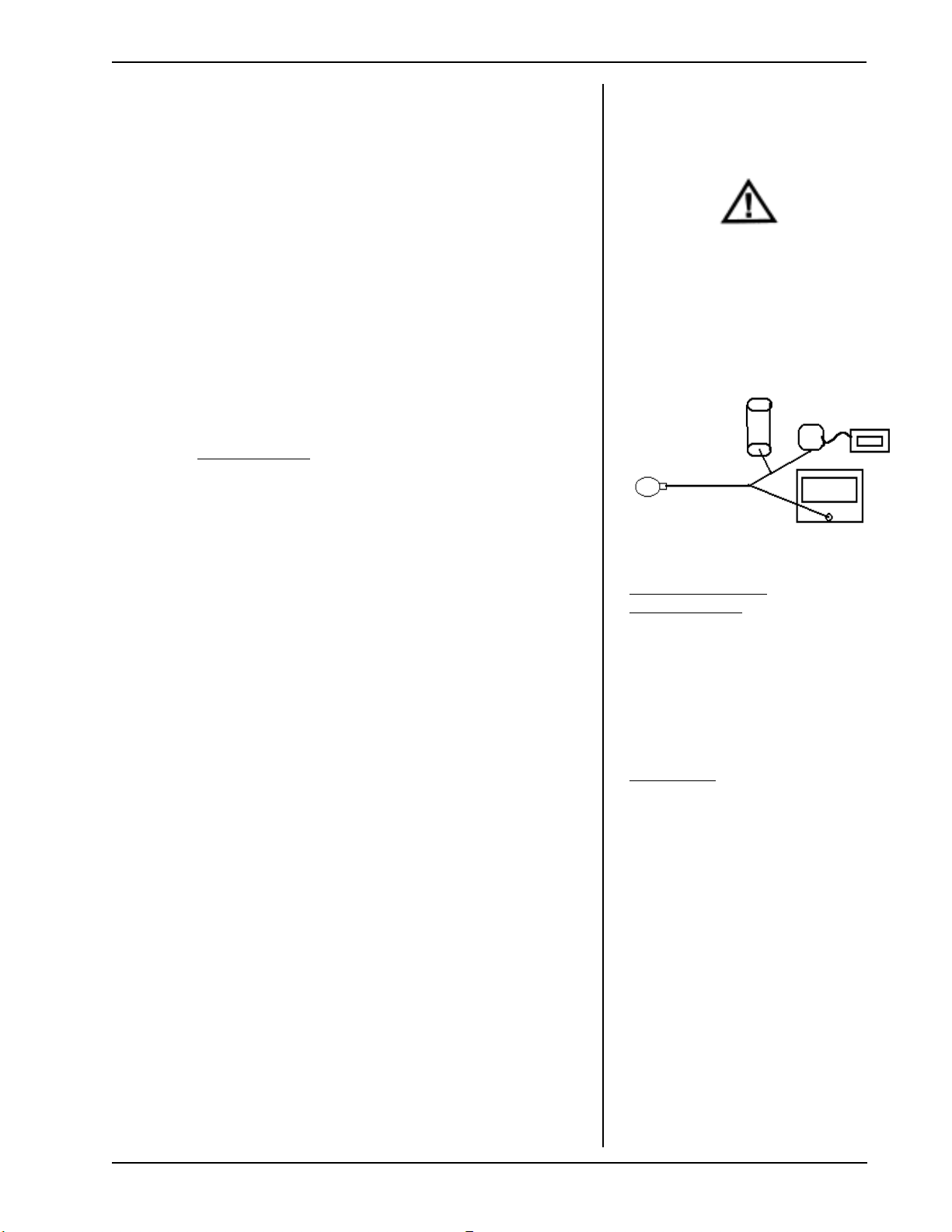
2.3.1 BP Calibration :
Need: 500cc vessel (approximate)
calibrated digital manometer
squeeze bulb with one-way valve
tubing and T fittings
PC with HyperT erminal *
serial cable
2.3.1.1 Connect: manometer, bulb, and 500cc vessel
to BP port with “T” connectors, Atlas to PC
with serial cable.
2.3.1.2 Turn AtlasON and start HyperTerminal on PC.
2.3.1.3 Enter commands on Serial interface:
Pangea> bp valve close<ENTER>
Pangea> bp safety off<ENTER>
2.3.1.4 Enter command:
Pangea> bp cal 5000
Do not press <ENTER> yet!
2.3.1.5 Raise pressure with bulb to as close to
50.00mmHg as possible or slightly higher. Let
the pressure bleed down toexactly
50.00mmHg. Now press <ENTER> . Take no
more than 3 minutes for this step.
2.3.1.6 Enter command:
Pangea> bp cal 25000<ENTER>
2.3.1.7 Repeat step 2.3.1.5 with 250.00 as target.
Press <ENTER> when pressure deteriorates to
250.00 mmHG.
2.3.1.8 Enter command:
Pangea> nvram write<ENTER>
2.3.1.9 Disconnect serial cable and instruments and
cycle power on Atlas. BP cal complete.
2.3.1.10 Verify accuracy of pressure settings
by repeating step 2.3.1.3 then 2.3.1.5 and
compare Atlas front panel reading with Setra
readout. Do this at 50.00mm and 250 mm Hg.
2.3 Calibration
2.3.1 BP Calibration
Caution: Improper use, storage, handling of compressed
gas vessels can cause injury
or death! Follow gas manufacturers safety processes.
500cc volume
Setra
Figure 2.3.1.1
*Access and set up
HyperT erminal:
1-Start
2-Settings
3-Control Panel
4-Add/Remove Programs
5-Windows Setup
6-Communications
7-selectHyperT erminal
8-APPL Y
Settings are:
9600 Baud, 8 bit word, 1 stop bit
no parity , no flow control
ANSI character set
Find HyperT erminal in Programs,
Accessories
2.3.2 ET CO2 Calibration: 623 Models only
Need: T ank of approximately 10% CO2, balance N
2
(certified) Blood Gas Mixture
Tubing and T connectors
Watertrap and scrubber
2.3.2.1 Insert water trap. Power up.
2.3.2.2 Place the instrument into Service Mode: Press
Date/Time Lead Select button.
2.3.2.3 Select Calibrate CO
2
Message “Remove CO2 water trap” will
appear.
SERVICE MANUAL 6200-43E REV . A WELCH ALLYN ATLAS MONITOR 7
2.3.2 ET CO2 Calibration
NOTE:Replace water trap
every 6 hrs of use. Treat
water trap and used
NasalCO2 Sample lines
as bio hazard material!
NOTE: The Scrubber looks
similar to a watertrap, but
is filled with white granules.
It is included with model
623XX.
Page 17
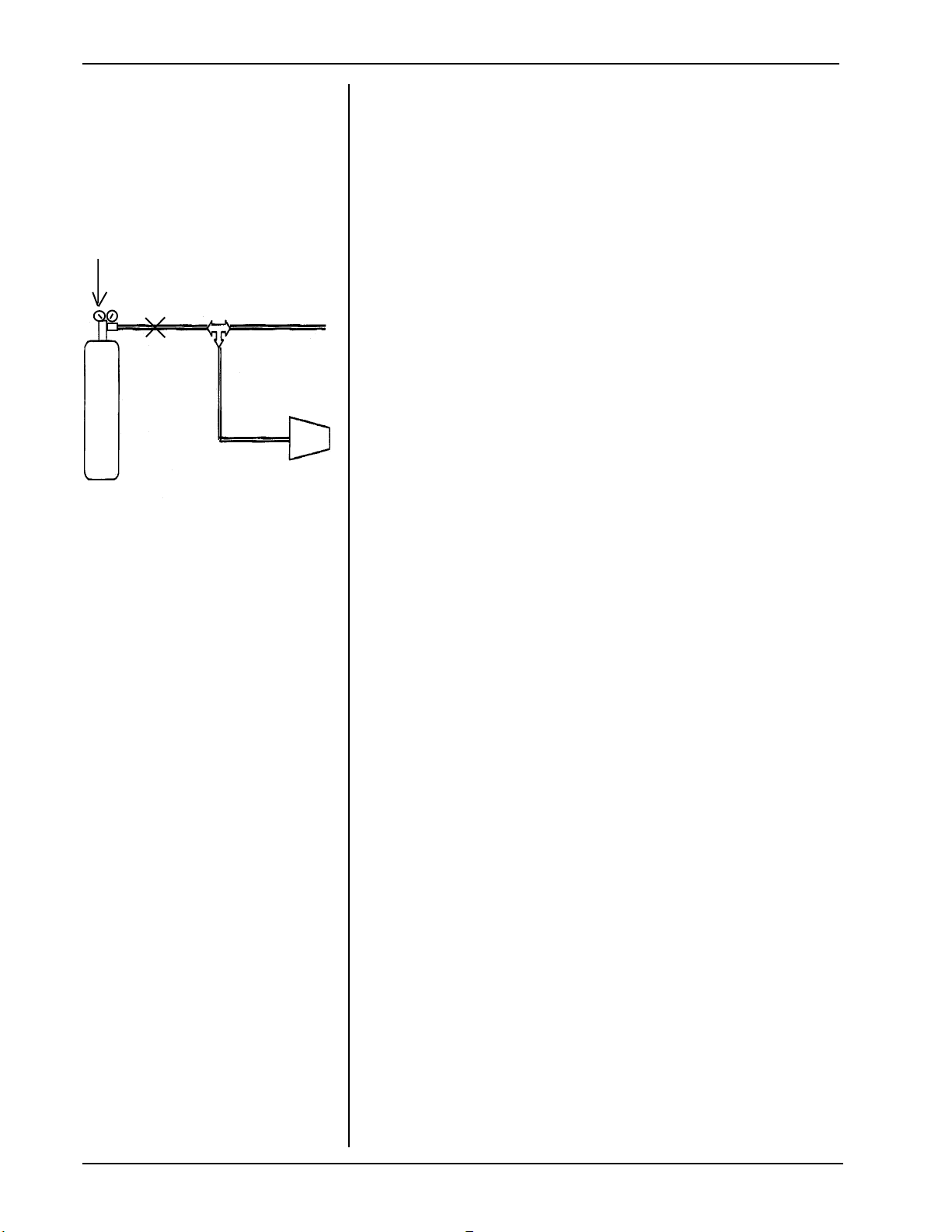
Section 2 - Service
Note
approximately 2 PSI.
: Adjust regulator to
valve
2
CO
watertrap
Figure 2.3.2.11
vent
2.3.2.4 Remove water trap from water trap socket .
2.3.2.5 Message “Install scrubber” will appear .
2.3.2.6 Attach scrubber to water trap.
2.3.2.7 Insert scrubber/water trap assembly into water
trap socket.
Message “Enter span gas value using
<Set> button” will appear.
2.3.2.8 Change the default value (10%) to the value of
span gas being used (calibrated 8% to 12%
concentration known to ±0.01%).
2.3.2.9 Press <BP Start/Cancel>
Message: “Sampling” appears while the
instrument is sampling the scrubber air.
2.3.2.10 When instructed, remove the scrubber from
the CO2 water trap. Do not remove water trap.
2.3.2.1 1 Attach the calibrated source of CO2 gas
to the CO2 side-stream sampling tube as per
Figure 2.3.2.1 1
2.3.2.12 Adjust the CO2 regulator just enough to
allow a small amount of gas to flow out of the
vent (approximately 3 PSI).
NOTE:Replace water trap
every 6 hrs of use. Treat
water trap and used
NasalCO2 Sample lines
as bio hazard material!
SR856: CO2 Calibration
beyond the year 2021
Important: Once positive flow is
established, let the it flow for one minute
before pressing the Continue button and
actually sampling.
After one minute, press the Continue
button to let the Atlas start sampling CO
2.3.2.13 Press <BP Start/Cancel>
Message: “CO2 calibration successful” or
“CO2 calibration failed” will appear on
th e CRT display .
(Note: Serial Communication is not the cause of a failure
if the Prion Serial appears in the Service Screen.
Therefore the problem is with the board or connections
and not serial communication problems.)
2.3.2.14 Press Trend button to Exit.
T o calibrate the CO2 system in years 2022 or later it is
necessary to reset the system clock to an earlier year ,
perform the calibration, and then set the clock to the
correct year again. The service center should keep a
record of this since the Cal display in the Service Mode
screen will be incorrect.
2.
.
8 WELCH ALL YN A TLAS MONITOR
SERVICE MANUAL 6200-43E REV. A
Page 18

Section 2 - Service
2.3.3 CO2 RESET
Need: Watertrap and Scrubber
2.3.3.1 Press the Date/Time button on the lower
right of the monitor. The Set Date and T ime
and Other Options menu will be displayed.
2.3.3.2 Select the Reset CO2 selection by pressing
the CO2/RESP ALARMS Off button.
CO2 Reset screen will appear.
2.3.3.3 Follow the instructions on the screen.
“Remove the CO2 watertrap”.
“Install the CO2 Scrubber onto the CO
watertrap.”
NOTE: The Scrubber looks similar to a watertrap,
but is filled with white granules. It is included
with model 623XX.
2.3.3 CO2 RESET
2
2.3.3.4 Remove the tubing from the watertrap and
attach the Scrubber to the watertrap.
2.3.3.5 Insert the watertrap/Scrubber combination
into the watertrap socket.
2.3.3.6 Messages: The system will report that it is
Sampling. The system will then report Reset
Complete.
2.3.3.7 Remove the watertrap/Scrubber from the
watertrap socket.
2.3.3.8 Detach the Scrubber from the watertrap and
reattach the tubing.
2.3.3.9 Replace the watertrap in the watertrap socket.
2.3.3.10 Press Trend to return to the waveform
screen.
NOTE: There may be a
message indicating a 5
minute Warming Up period.
SERVICE MANUAL 6200-43E REV . A WELCH ALLYN ATLAS MONITOR 9
Page 19

Section 2 - Service
2.3.4
PRINTER CALIBRATION
Note: Two lines are displayed:
Waveform +128, Text +70
These two numbers are factory
defaults and a good starting point
if the system is printing very
poorly or not at all.
The LEFT<SET> button controls
the Waveform setting, up and
down. The RIGHT <SET> button controls the Text setting, up
and down. Make changes tothe
settings as needed, where a
larger number = darker printing
and a smaller number = lighter
printing. Make initial changes of
about 10 points each time. After
making an adjustment, press
<TREND> to exit the Service
Mode.
2.3.4 PRINTER CALIBRA TION
Need:
PC with HyperT erminal
Serial cable
Connector
2.3.4.1 Use HyperTerminal to get strobe width
settings for printer normal for waveforms text for trend
Advanced configuration printing:
Pangea> nvram get
printer_strobe_width_normal<ENT>
(normal value 130)
Pangea> nvram get printer_strobe_width_text<ENT>
(normal value 70)
2.3.4.2 Change values - larger number for darker
printing. Change with:
Pangea> nvram set printer_strobe_width_normal XX X
Pangea> nvram set printer_strobe_width_text YYY
2.3.4.3 Test and reset until satisfied.
2.3.4.4 Press Trend button to exit the Service Mode.
2.3.5 BA TTER Y VOLTAGE
CALIBRA TION
2.3.5 BA TTERY VOL T AGE CALIBRA TION for models
622XX and 623XX.
NOTE: CHECK BA TTERY VOL T AGE CALIBRA TION
AFTER REPLACING MAIN PCB.
Need:
DC power supply rated: 7 VDC at 5A
Battery eliminator cable - Atlas battery plug on one
end, interface to the power supply on the other.
There should be access for voltmeter probes at
the Atlas end of the cable when it is installed
DMM / DVM with 10mV resolution on a 10V scale
PC with HyperT erminal
Serial cable and connector
2.3.5.1. Connect serial cable to PC and Atlas
2.3.5.2 Remove battery from Atlas
2.3.5.3 Set the power supply to 6.8V +/- 200mV
2.3.5.4 Connect the power supply to the Atlas battery
connector .
2.3.5.5 Turn At las ON.
2.3.5.6 Reduce the power supply to 6.0V
10 WELCH ALL YN A TLAS MONITOR
SERVICE MANUAL 6200-43E REV. A
Page 20

Section 2 - Service
2.3.5.7 Measure the voltage at the battery connector
(at the Atlas) to the nearest 10mV .
NOTE: Do not measure at the power supply , since
cable resistance will introduce error.
2.3.5.8 At the HyperT erminal, type:
Pangea> power cal XXXX<ENTER>
(where XXXX represents the measured voltage in
millivolts no decimal point.) For example, if you
measured 6.010V at the battery connector , use the
command “power cal 6010<ENTER>”.
2.3.5.8 The Atlas will respond:
raw = ZZZZ mV true = 6010 mV OK
(where ZZZZ is the raw uncalibrated reading that the
instrument made.)
2.3.5.9 Reduce the power supply to 5.6 volts. Y ou
should soon hear the “low battery” alarm.
2.3.5.10Measure the voltage at the battery connector
to the nearest 10mV .
2.3.5.1 1At the HyperT erminal, type:
Pangea> power cal XXXX<ENTER>
(where XXXX represents the measured voltage in
millivolts no decimal point.) For example, if you
measured 5.590V at the battery connector , use the
command “power cal 5590<ENTER>”.
2.3.5.12
raw = ZZZZ mV true = 5590 mV OK
The Atlas will respond:
(where ZZZZ is the raw uncalibrated reading that the
instrument made.)
2.3.5.13
Pangea> hw reset<ENTER>
2.3.5.14 Turn Atlas OFF and remove the power
supply .
2.3.5.15 Re-Install the battery .
SERVICE MANUAL 6200-43E REV . A WELCH ALLYN ATLAS MONITOR 11
Finish by typing: (this will re-boot A TLAS)
Page 21

Section 2 - Service
2.3.6 TEMPERATURE
MEASUREMENT
SUBSYSTEM
CALIBRATION
2.3.6 TEMPERA TURE MEASUREMENT
SUBSYSTEM CALIBRA TION:
Need:
PC
Serial Cable
HyperTerminal
1kOhm - 2kOhm 1% 1/2watt resistor
Large RCA plug (1/4”) 2 conductor
Short length of wire (optional)
Soldering iron and solder
2.3.6.1Prepare Resistor/Plug assembly .
Solder the resistor across RCA plug
terminals.
2.3.6.2 Plug the resistor assembly into the Atlas
T emperature jack.
2.3.6.3 Connect the Atlas to the PC serial port.
2.3.6.4 Turn the Atlas ON.
NOTE: T emperature display will show a valid
temperature.
2.3.6.5 Start HyperTerminal on the PC.
2.3.6.6 At the Pangea prompt, type:
Pangea>temp cal xxxxxx<ENTER>
(where the xxxxxx is the value of the precision resistor
in centiOhms- Specify the Ohms, tenths, and
hundredths of Ohms with no decimal point- for
example, a 1200.00 Ohm resistor would be:
Pangea>temp cal 120000<ENTER>
2.3.6.7
Wait four seconds then type:
Pangea>temp state<ENTER>
2.3.6.8 Displayed resistance will be within 0.5
Ohms of the value that you entered.
The Offset should not exceed 5.0 Ohms.
NOTE: The system will silently fail (without error) if it
is unable to calibrate properly . Therefore you
must manually verify that this resistance is
correct.
2.3.6.9 Turn the Atlas OFF.
2.3.6.10Unplug the resistor/plug assembly.
2.3.6.1 1Remove the serial cable.
2.3.6.12Check the accuracy of the
temperature sensing system using the
process described in Section 2.2.1 1
12 WELCH ALL YN A TLAS MONITOR
SERVICE MANUAL 6200-43E REV. A
Page 22

Section 2 - Service
2.3.7Set battery charging voltage:
Specification :No Load: 6.85VDC
Need: DVMM
2.3.7.1Remove battery from unit and unplug.
2.3.7.2Use DVMM to check across right pin (+)
and left pin (-) when viewed looking into
the battery compartment.
2.3.7.3Adjust potentiometer R338 to obtain
6.85VDC. (It is located at the right of the
battery jack.
Turn it counterclockwise to increase the
charging voltage.
2.3.7 Set Battery Charge
Voltage
SERVICE MANUAL 6200-43E REV. A WELCH ALLYN ATLAS MONITOR 13
Page 23

4X noitautiS noitidnoC noitcA sliateD decnavdA
11A
1B
1C
1D
noitarugifnoC
tesresu(
gnisusecnereferp
slortnoclenaptnorf
1E
ezilaitinI
gnisuMARVN
lanimretrepyh
1F
daolnwoD
metsysgnitarepo
swodniwgnisu
1G
1H
tarbilaCeR
?saltA
,rewoP,PB(
erutarepmet
)
OCtondna
2
1I
ecneuqeS
erawtfoS
edargdpU
Software Chart 2.4.1
22A
deliaf
33A
deliaf
44A
2B
draobniaM
3B
draobUPC
4B
onsahtinU
smelborp
2C
gnicalpertsuJ
.draobniaM
lanigiroehT
sidraobUPC
.KO
3C
gnicalpertsuJ
.draobUPC
lanigiroehT
sidraobniaM
.KO
4C
wenehtesU
ytilitudaolnwod
"exe.ld_salta"
niaMecalpeR
ezilaitini,draob
dna,marvn
.etarbilacer
UPCecalpeR
daoldnadraob
gnitarepo
.metsys
.deriuqer
2D
3D
4D
tonlanimreTrepyH
.noitarbilac
SEY
sdaol"exe.ld_salta"
llasetirwrevohcihw
sgnittesecnereferp
decnavdA(
2E
lanimreTrepyHdeeN
dnamarvngnittesrof
3E
elifexe.ld_saltadeeN
4E
ON
eliftxt.nommoc_marvn
htiwsgnittessuoiverp
,riaperretfA.stluafed
resullakcehcesaelp
)uneMnoitarugifnoC
sgnittesMRALAdna
yawehtmehttesdna
.deviecersawtinueht
2F
evobasaemaS..seY
SEY
3F
evobasaemaS..seY
ON
4F
SEY erawtfos
UPCni
2G
:ON gnitarepo
sawhcihwUPC
.dehcuotnu
3G
SEY
erawtfos
UPCni
4G
ON htiW
sedisernoitamrofni
2H
nisedisermetsys
3H
ON
sedisernoitamrofni
4H
exe.ld_salta
ehtmargorp
noitarbilac
erastnatsnoc
.degnahcton
SEY eht
ehtfoMARVN
niamwen
tonlliwdraob
tcerrocehtevah
noitarbilac
.stnatsnoc
nuR.1
exe.ld_salta
mralakcehC.2
rehtodnasgnittes
remusnoc
ecnereferp
decnavda
noitarugifnoc
.sgnittes
2I
MARVNteS-1
etarbilaceR-2
mralakcehC-3
sgnittes
3I
daolnwod-1
metsysgnitarepo
mralakcehC-2
rehtodnasgnittes
remusnoc
ecnereferp
decnavda
noitarugifnoc
sgnittes
4I
UPChtoB
niamdna
deliafdraob
Section 2 - Service
gnicalpeR
UPCehthtob
niaMdna
.sdraob
htobecalpeR
esu,sdraob
,exe.ld_salta
,erugifnocer
.etarbilac
.noitarbilac
lanimreTrepyHdeeN
dnamarvngnittesrof
evobasaemaS..seY
SEY
SEY
erawtfos
UPCni
SEY eht
sedisernoitamrofni
ehtfoMARVN
niamwen
tonlliwdraob
tcerrocehtevah
noitarbilac
.stnatsnoc
sgnittes
exe.ld_saltanuR-1
marvnteS-2
etarbilaceR-3
mralates/kcehC-4
14 WELCH ALLYN ATLAS MONITOR SERVICE MANUAL 6200-43E REV. A
Page 24

Section 2 - Service
2.4 Downloading Operating System
When required: to load latest revision software*
o na fully functioning Atlas or to reload software
after replacing the MCU board. The
atlas_dl.exe program loads the following files:
atlas.out.gz
nvram_common.txt
nvram_(model#).txt **
nvram_(language).txt **
Equipment or supplies required:
PC with Windows ‘95/NT
Serial cable with connector: (COM1to PC)
File : atlas_dl.exe
2.4.1 Connect serial cable between Atlas and
PC COM1
2.4.2 Double click “atlas_dl.exe” explorer window
2.4.3 After downloading is complete, check alarm
and other User controlled advanced
configuration settings since these are ‘reset’ by
this downloading process.
2.4 Downloading Operating System
(when upgrading software or
replacing CPU board)
**Note: Hyperterminal
queries the Atlas to determine which model number
and language to download.
Note: If Atlas calibration
was satisfactory prior to
downloading software
then recalibration is not
required.
Downloading Operating System complete
2.5 Downloading NVRAM files with Hyperterminal*.
The NVRAM resides on Main Board. Hyper
terminal loads the following files:
cal_init.txt
common.txt
(model#).txt **
(language).txt,**
printer .txt (if required),
or no_printer.txt.
2.5.1Connect serial cable between Atlas and
PC COM1 as in 2.4 above.
2.5.2Open HyperT erminal program on PC:
ST ART
PROGRAMS
ACCESSORIES
HYPERTERMINAL
2.5.3Turn Atlas ON. You should see some
version information and a prompt:
Pangea>
2.5.4 Transfer Text files:
(TRANSFER/SEND TEXT FILE)
NVRAM_CAL_INIT .TXT (only if main board has been
replaced)
2.5 Downloading NVRAM
T ext files
after replacing Main Board
*Configure HyperT erminal
9600 Baud
8 bits
1 stop bit
no parity
no flow control
SERVICE MANUAL 6200-43E REV . A WELCH ALLYN ATLAS MONITOR 15
Page 25

Section 2 - Service
2.5 Downloading NVRAM
T ext files
when replacing Main Board
continued
2.6 Downloading Soft-
ware &
NVRAM T ext files
after replacing Main Board
AND CPU board
NVRAM_COMMON.TXT
NVRAM_NO_PRINTER.TXT
or
NVRAM_PRINTER.TXT
NVRAM_(model 200,210,220).TXT
NVRAM_<LANGUAGE>.TXT
2.5.5 After these text files are transferred,
T ype the following serial commands to update
the serial number:
nvram set serial___ (last 3 digits of serial#)
nvram write
hw reset (hardware reset restartsAtlas and
saves the new settings)
2.5.6 Verify the serial number correct
2.5.7 Recalibrate Atlas unit. After calibration is
complete.
2.5.8 Check alarm settings and User selected
advanced Configurations
2.6 Downloading Software & NVRAM T ext files
2.6.1 Use atlas_dl.exe as in step 2.4. to Program
ne w CPU board.
2.6.2 Use HyperTerminal as in step 2.5 to set
NVRAM on new Main Board.
2.6.3 Recalibrate Atlas
2.6.4 Check alarm settings and User selected
advanced Configurations
16 WELCH ALL YN A TLAS MONITOR
NOTE: Firmware Download
Software versions of OEM boards are not field
upgradeable. (SpO2 boards or the CO2 board.)
Replace the subsystem board with a higher
(current) version if necessary .
SERVICE MANUAL 6200-43E REV. A
Page 26

Section 2 - Service
2.7 Product Model Number Structure
621S0* ECG, Nonin SpO2, NIBP
621SP* ECG, Nonin SpO2, NIBP , Printer
622S0** ECG, Nonin SpO2, NIBP , Temp, Respiration, Battery, RS232, Nurse Call
622SP** ECG, Nonin SpO2, NIBP , Temp, Respiration, Battery, RS232, Printer , Nurse Call
622N0** ECG, Nellcor SpO2, NIBP , Temp, Respiration, Battery, RS232, Nurse Call
622NP** ECG, Nellcor SpO2, NIBP , Temp, Respiration, Battery, RS232, Printer , Nurse Call
623SP** ECG, Nonin SpO2, NIBP , ETCO2, T emp, Respiration, Battery , RS232, Printer , Nurse Call
623NP** ECG, Nellcor SpO2, NIBP , ETCO2, T emp, Respiration, Battery , RS232, Printer , Nurse Call
SUFFIX:
Use letter designation for language localization as follows:
E = English, F= French, G= German, I= Italian, S= Spanish, P= Portuguese C = Chinese, J= Japanese
Use number designation for line cord localization as follows:
1 = US, Canada, Japan Version
2 = European Version
4 = United Kingdom Version
6 = Australian Version
Specifications: See Operator Manual
Specifications for all of the above listed models of Atlas including performance, accuracy ,
range, size, weight, power, environmental, are documented in an appendix to the User
Manual.
* Model 200 Main Board and Schematic 200
** Model 220 Main Board and Schematic 220
SERVICE MANUAL 6200-43E REV. A
WELCH ALLYN ATLAS MONITOR 17
Page 27

Section 3 - Troubleshooting
3.1 Functional Test and Initial Diagnostic
1.Review customer complaint and determine if it is
safe to plug in and turn on Atlas
2.Plug in Atlas, no sensors attached.
3.Check for AC~ LED lit.
4.Install paper in printer if fitted.
5.Turn on power
6.Green light in power button.
7.Loud beep when button pressed.
8.Three dashes in SYSTOLIC.
9.Three dashes in DIASTOLIC.
10.Two dashes in SpO2 (takes several seconds after BP
dashes come on).
11.Three dashes in PULSE (takes several seconds after
BP dashes come on).
12.Pleth: none, or a single bar at the bottom, or two bars at
the bottom.
13.No lights in TEMP.
14.No lights in ALARMS OFF buttons.
15.X lit on AUTO.
16.AC~ lit
17.CRT display comes on slowly if cold, quickly if still warm
from last use.
18.May see version string in center if comes on quickly, not
a problem if not seen because it comes on slowly.
19.CRT: three dashes for Heart Rate
20.Heart picture
21.Lead select symbol
22.Scale bar
23.One or two lines of dashes for waveforms – depends
upon settings.
24.Three dashes for MAP – or blank, depends upon
settings.
25.Error message(s) at bottom of screen?
Note: “Idle” screen is normal
waveform display.
26.If 622 or 623, pull AC cable. Should be no change
except AC~ unlit.
26.1. If errors of low, very low or depleted battery,
or if system dies, plug back in and repeat
test in 2 hours.
SERVICE MANUAL 6200-43E REV. A
WELCH ALLYN ATLAS MONITOR 1
Page 28

Section 3 - Troubleshooting
3.1 Functional Test and Initial Diagnostic
Plug AC back in.
MENU TESTS
27.Press <DA TE/TIME><TREND>
28.Get Advanced Configuration menu.
29.Write down all settings for resetting to customer preference later.
30.Set language to your native tongue if necessary to
allow you to write down the other settings. The top
item is always the language, press either <SET> button
to step through list.
31.Press <PRINT> if printer fitted.
32.Press <TREND> to return to idle screen.
33.Press <DA TE/TIME>
34.Get date/time menu.
35.V erify date/time, set if necessary .
35.1. Bad date may indicate battery problem. If
date was bad, turn off unit, pull power cable,
wait 5 minutes reconnect power cable, turn
on unit. Check date again.
35.1.1. If date comes back bad: Replace
main board Model 200. Model 210,
220, if battery not dead replace main
board.
Press Date/Time to return to waveform screen if needed.
36.Press <DATE/TIME><LEAD SELECT>
37.Get Service Mode menu.
38.Examine version/configuration data in lower half of
menu, and write it all down.
39.Press <SELECT> to highlight Reset to factory de-
faults.
40.Press <BP START/CANCEL> to reset configuration.
41.Press <TREND> to return to idle screen.
42.Press <DA TE/TIME><TREND>
43.Get Advanced Configuration menu.
44.Set language to your native tongue if necessary
44.1. We have just reset to factory defaults.
Compare settings to factory defaults appropriate for the country – in Operator manual. Ifno t
matching, indicates memory problems.
Changing only the language should not change
any of the other factory default settings.
45.Press <DATE/TIME><LEAD SELECT>
2 WELCH ALL YN ATLAS MONITOR
SERVICE MANUAL 6200-43E REV. A
Page 29

Section 3 - Troubleshooting
46.Get Service Mode menu.
47.Press <Select> to highlight CRT test pattern.
48.Press <BP START/CANCEL> to show test pattern.
Examine display .
49.Press any key to end display .
50.Press <Select> to highlight Printer test pattern (if
fitted).
51.Press <BP START/CANCEL> to start test pattern.
52.Printer should print test pattern.
53.Press any key to end display .
54.Examine printout.
55.Press <Select> to highlight LED test .
56.Press <AUTO> to turn on all LEDs .
57.Press <BP START/CANCEL> to show automatic test
pattern.
58.Watch for a while, look for glitches in pattern.
59.Press <Set> to go to manual mode and step through
individual segments if needed to observe a problem.
3.1 Functional Test and Initial Diagnostic
60.Press <Select> to highlight Button test.
61.Press <BP START/CANCEL> to start test.
62.Press every button on system, <BP ST ART/CANCEL>
last.
62.1. Verify that buttons match up with their names,
and that all buttons are functional.
62.1.1. If names don’t match, indicates
memory corruption: Replace main
board
63.Press <Select> to highlight Display A/D channels
(three or four screens worth)
63.1. Write down all values for later review.
63.2. Press <Set> and write down all values for
each screen.
64.Press <Trend> to return to Idle screen.
65.Connect the BP port to the BP simulator.
66.Set the simulator for a normal reading (140/80,
100BPM, NSR).
67.Press <BP START/CANCEL>
67.1. System should start pump, display manom-
eter value in SYSTOLIC LED; this value
should track and be very close to pressure
BP test
SERVICE MANUAL 6200-43E REV. A
WELCH ALLYN ATLAS MONITOR 3
Page 30

Section 3 - Troubleshooting
3.1 Functional Test and Initial Diagnostic
displayed by manometer in BP simulator (if
fitted). Largest number shown in SYSTOLIC
should be very close to the Initial pressure
setting recorded above from Advanced
Configuration.
67.2. System should step down pressure, showing
step values in SYSTOLIC LED, and then display correct SYSTOLIC and DIASTOLIC
values. System may show MAP value depending upon country .
68.Press <DA TE/TIME><TREND> to get to Advanced
Configuration menu.
69.Press <Select> to highlight Initial pressure.
70.Press <Set> to change Initial pressure to 280 mmHg.
71.Press <Select> to highlight MAP.
72.Press <Set> to change MAP to Yes.
73.Press <TREND> to return to idle screen.
74.Press <BP START/CANCEL>
75.System should start pump, display manometer value in
SYSTOLIC LED; this value should track and be very
close to pressure displayed by manometer in BP
simulator (if fitted). Largest number shown in SYSTOLIC should be very close to the Initial pressure
setting of 280 mmHg.
75.1. If pressure shown exceeds 300 mmHg:
Recalibrate BP
76.System should step down pressure, showing step
values in SYSTOLIC LED, and then display correct
SYSTOLIC and DIASTOLIC values. System should
show MAP value. MAP value should match what is
shown by simulator.
77.Set simulator to highest Systolic <=250, lowest Diastolic >= 30, and lowest heart rate >=30.
78.Press <AUTO>
79.X goes unlit, 1 flashes for 10 seconds.
80.20 seconds after 1 stops flashing, BP measurement
starts.
81.BP reading as above.
81.1. If BP does not start: Replace main board
81.2. If BP measurement incorrect recalibrate
4 WELCH ALL YN ATLAS MONITOR
SERVICE MANUAL 6200-43E REV. A
Page 31

Section 3 - Troubleshooting
82.No less than 30 seconds after completing the measurement another measurement should start. While it is
pumping up, press <BP ST ART/CANCEL>. Measurement stops immediately and pressure is dumped (as
seen on manometer on simulator).
82.1. If measurement does not stop immediately:
Main board or button.
82.2. If pressure does not drop below 10mmHg
immediately: Main board
83.Press <AUTO> and X lights up (not flashing).
84.Disconnect the tubing from the BP port on the Atlas.
85.Press <BP START/CANCEL> and note the time (to the
second).
86.The BP should abort with an alarm after no longer than
one minute.
3.1 Functional Test and Initial Diagnostic
87.Cycle power on Atlas, connect a 5 lead cable set to the
simulator.
88.Configure the simulator for NSR 100BPM and Impedance Respiration.
89.Plug the cable into Atlas.
90.Press <DA TE/TIME> <TREND> to access Advanced
Configuration menu.
91.Press <Select> to highlight ECG lead set and press
<Set> to select 5 wire.
92.Set ECG gain to Automatic.
93.Set ECG speed to 25mm/s.
94.Set ECG bandwidth to Monitor.
95.Set Second trace selection to ECG.
Press <TREND> to return to idle screen
Should see:
95.1. ECG cascading onto second line
95.2. Scale bar on left of top line
95.3. Heart rate displayed as set on simulator
95.4. Lead Selected = II
95.5. Pulse tone high pitched
ECG
Note: Simulator must support impedance respirator .
Press <LEAD SELECT> and step through each of the lead
settings.
Should see:
95.6. Different looking ECG waveforms
95.7. Heart Rate will go to dashes and alarms on
some leads
96.Set lead selected to II
SERVICE MANUAL 6200-43E REV. A
WELCH ALLYN ATLAS MONITOR 5
Page 32

Section 3 - Troubleshooting
3.1 Functional Test and Initial Diagnostic
97.Press <DA TE/TIME><TREND> to access Advanced
Configuration menu.
98.Change Second trace selection to Respiration.
99.Press <TREND> to return to idle screen.
100. Should see:
100.1. ECG on top line
100.2. Scale bar on left of top line
100.3. Heart rate displayed as set on simulator
100.4. Lead Selected = II
100.5. Pulse tone high pitched
100.6. Respiration trace on second line
100.7. Respiration rate displayed as set on simula-
tor.
101. Disconnect ECG simulator
SpO
2
Temp
102. Connect SpO2 cable and cuff and install cuff on
simulator (or your finger).
103. Set simulator to normal readings.
104. See pleth signals immediately .
105. See SpO2 percentage within several seconds .
106. See Pulse display at the same time as SpO
2
percentage.
107. Disconnect SpO2 cuff from simulator .
108. See error “SpO2 cuff not detected”.
109. Unplug SpO2 cable from Atlas.
1 10. See error “SpO2 cable not detected”.
1 1 1. T emp display is blank.
1 12. Connect temp probe.
1 13. See temp display of ambient temperature.
1 14. Disconnect temp probe.
1 15. Temp display becomes dashes. No alarm or error
CO
2
6 WELCH ALL YN ATLAS MONITOR
1 16. Press <DATE/TIME><TREND>
1 17. Get Advanced Configuration menu.
1 18. Set Second trace selection to CO
2.
1 19. Press <TREND> to return to idle screen.
120. Insert watertrap with tubing attached.
121. Should see:
121.1. Hear pump motor start.
121.2. See solid line waveform on lower trace.
121.3. See dashes in Respiration Rate.
121.4. See dashes in mmHg (or % or kPa, as
configured).
SERVICE MANUAL 6200-43E REV. A
Page 33

Section 3 - Troubleshooting
122. Breathe gently and repeatedly over end of tubing
123. Should see:
123.1. See waveform within seconds of breathing
123.2. See respiration rate non zero within one
minute.
123.3. See CO2 concentration non zero within one
minute.
3.1 Functional Test and Initial Diagnostic
124. System must have been plugged in for 24 hours for
a real battery test to guarantee that battery is fully
charged, but for functional test we can try it:
125. Press <DA TE/TIME><LEAD SELECT>
126. Get Service Mode menu
127. Press <SELECT> to highlight Battery test
128. The menu reports
Battery Low Time XXX and
Battery Dead Time YYY
These are the results from the last battery test. The
Battery Low Time is the time in hours and minutes
that the battery ran in the last test until the Low
Battery alarm started, and the Battery Dead Time is
the time from the beginning of the Low Battery Alarm
until the system turned itself off when the battery
voltage reached the cutoff level.
129. Write down the Battery Low Time and Battery Dead
Time
130. Unplug AC cord to start battery test
131. The timers will begin. Leave the system until it
powers down. Plug in AC and turn the system on,
enter the Service Mode menu, select Battery T est
again, and write down the new values. Compare
these to the previous values, and to the minimum
specification: Battery Low Time = 1 Hour
Battery Dead Time = 10 Minute minimums.
132. Replace the battery if performance falls below
specification
BA TTER Y
Note: 2:08 means 128
minutes which is the default
setting indicating a battery
test has never been made
before.
NOTE: Configuration settings for printing are different for
text pages (Advanced Configuration and Trend displays)
and for waveforms.
133. Connect ECG simulator to generate a sample
waveform.
SERVICE MANUAL 6200-43E REV. A
PRINTER
WELCH ALLYN ATLAS MONITOR 7
Page 34

Section 3 - Troubleshooting
3.1 Functional Test and Initial Diagnostic
134. Press <PRINT> and look at waveform printout. Look
for darkness, thickness of lines, legibility of text,
blurring, “blooming” of text.
135. Press <DATE/TIME><TREND>
136. Get Advanced Configuration menu.
137. Press <PRINT> and look at text printout.
137.1. If feeding problems: Mechanical inspection
of printer, replace motor , drive platten.
137.2. If waveforms too light or dark: Calibrate
137.3. If text too light or dark in configuration screen,
press <Select> until “Printer test pattern” is
highlighted then press <HR Alarms Off>
button, then press <Set> to lighten or darken
print.
137.4. If incorrect printout, missing elements, miss
ing grid, etc: Troubleshoot further
Software/firmware
ALARMS/SOUNDS
138. Review versions written down earlier and compare
to latest available, and also make sure that all
components are compatible with each other . See
table 2.6 in this document.
Power-on beep
139. Tur n off system, and turn on. Should hear loud
Power-on beep.
ECG pulse tone, pulse volume control, saving settings, <HR ALARMS Off> button
140. Connect ECG simulator.
141. Should hear: heart rate beep, at constant high pitch
142. Press SpO2 volume button “-“ 8 times. Should get
quieter and finally silent.
143. Press <DA TE/TIME><PRINT> to Save settings.
144. Turn system off and back on.
145. Pulse tone should be silent even though heart rate is
shown.
8 WELCH ALL YN ATLAS MONITOR
146. Press SpO2 volume button “+” 8 times. Should get
audible and then louder.
147. Disconnect ECG cable
SERVICE MANUAL 6200-43E REV. A
Page 35

Section 3 - Troubleshooting
3.1 Functional Test and Initial Diagnostic
148. Should hear T echnical alarm and see error message.
149. Press <HR ALARMS Off> button.
150. Should stop T echnical alarm sound, and erase error
message, and light LED in <HR ALARMS OFF>
button.
151. Press <HR ALARMS OFF> button again.
152. Should hear T echnical alarm sound, see error
message, LED unlit in <HR ALARMS Off> button.
153. Turn system of f and on.
SpO2 pulse tone
154. Attach SpO2 cable and cuff, and attach to simulator
or finger.
155. Should hear heart rate beep, different tone than
when ECG was connected.
156. Change SpO2 setting on simulator , or hyperventilating,
hold breath, should hear tone pitch change up or down
tracking simulator setting.
Limit Alarm, alarm volume control, Silence button,
T echnical Alarm, <SpO2 ALARMS Off> button
157. Press right <Select> button until SpO2 LO is flashing, press right <Set> UP to change SpO2 LO
setting to 99.
158. Wait until SpO2 LO stops flashing.
159. Set simulator to SpO2 at 90%.
160. Should hear Limit alarm.
161. Press <Alarm Volume> “-“ eight times. Should get
quieter but not silent.
162. Press <Alarm Volume> “+“ eight times. Should get
louder.
163. Press <Silence> and start stopwatch. Should be
quiet for the time set in Advanced Configuration
menu, then alarm comes back on.
164. Disconnect SpO2 cable from Atlas.
165. Should hear technical alarm, see error message
“SpO2 cable not detected”
166. Press <SpO2 ALARMS Off> button.
167. Should stop T echnical alarm sound, and erase error
message, and light LED in <SpO2 ALARMS OFF>
button.
168. Press <SpO2 ALARMS OFF> button again
169. Should hear T echnical alarm sound, see error message, LED unlit in <SPO2 ALARMS Off> button.
170. Turn system off and back on.
SERVICE MANUAL 6200-43E REV. A
WELCH ALLYN ATLAS MONITOR 9
Page 36

Section 3 - Troubleshooting
3.1 Functional Test and Initial Diagnostic
<CO2/RESP ALARMS Off> button
171. Press <DATE/TIME><TREND>
172. Get Advanced Configuration menu
173. Set Second trace selection to CO
174. Press <TREND> to return to idle screen
175. Insert CO2 watertrap with hose
176. Breath into hose until waveform is displayed
177. Remove CO2 watertrap
178. Should hear T echnical alarm and see error message. - “CO2 watertrap not detected”
179. Press <CO2/RESP ALARMS Off> button.
180. Should stop T echnical alarm sound, and erase error
message, and light LED in <CO2/RESP ALARMS
OFF> button.
181. Press <CO2/RESP ALARMS OFF> button again.
182. Should hear T echnical alarm sound, see error
message, LED unlit in <CO2/RESP ALARMS Off>
button.
183. Turn system off and back on
2
<BP ALARMS Off> button
184. With no hose connected to BP port, press <BP
ST ART/CANCEL> button
185. Place finger over BP port, blocking flow, causing BP
to detect overpressure and abort
186. Should hear T echnical alarm and see error message. - “Check blood pressure cuff”*
187. Press <BP ALARMS Off> button.
188. Should stop T echnical alarm sound, and erase error
message, and light LED in <BP ALARMS OFF>
button.
189. Press <BP ALARMS OFF> button again.
190. Should hear T echnical alarm sound, see error
message*, LED unlit in <BP ALARMS Off> button.
191. Turn system off and back on.
Battery tone
192. Disconnect AC power on running system.
193. Connect BP hose to simulator
194. Press <AUTO> to select 1 minute intervals
195. Wait for battery to run down. With fully charged
battery , after no less than 50 minutes, should hear
single tone, get message that system will shut down
in 10 minutes.
10 WELCH ALL YN ATLAS MONITOR
SERVICE MANUAL 6200-43E REV. A
Page 37

Section 3 - Troubleshooting
196. Should hear tone again in two minutes, and again
two minutes after that.
197. Five minutes after first message, should start hearing tone every minute, and get message that 5
minutes remain until shutdown.
198. T en minutes after first message, should hear technical alarm, see a printout of Trend data if there is any
unprinted trend data accumulated, (which there is,
we have been running BP measurements) and error
message that system shutdown is imminent.
3.1 Functional Test and Initial Diagnostic
All the possible error messages are documented in an
appendix to the Operator’s Manual.
SELF DIAGNOSTIC
ERROR MESSAGES
SERVICE MANUAL 6200-43E REV. A
WELCH ALLYN ATLAS MONITOR 11
Page 38

Section 3 -Troubleshooting
3.2 Chief Complaint, Cause and Corrective Action
Complaint
Power
Will not power up in AC
LEDs
Random LSD segments unlit
Subsystem
LED intermittent, dim, flickering
Buttons
Button not functional
Button sticking under front bezel
Button intermittent or difficult to
make contact
sounds
No sound at all
LEDs
unlit
Cause
No wall power
Wrong wall power voltage/frequency
Fuse in power supply
Fuse in neutral wire
Power supply failure
Failed LED
Subsystem problem Check subsystem LED 1
Failed LED
Failed switch
Failed subsystem
Possible loose display board
Failed switch
Failed speaker or disconnected
Failed main board
Software corruption
LED 1
Replace Display board
Button 1
Check subsystem
Tight display board mounting screws.
Button 1
Reload software
sound 1
Corrective Action
Battery
Insufficient
Printer
Feed problems
Waveform print quality
Text print quality
Not functional
Feeding but not printing
CRT
CRT is blank
life
Failing battery
Paper inserted incorrectly
Door not latched
Failed printer
Software adjustment needed
Software adjustment needed
Failed printer
Printer cable
Paper inserted backwards
Wrong kind of paper
Failed printer
CRT cables
Failed CRT
Failed Deflection board
Failed Main Board
Battery 1
Printer 1
Printer 1
Printer 1
Printer 1
Printer 1
CRT 1
Reinstall software
12 WELCH ALLYN ATLAS MONITOR
Service Manual
6200-43E
Rev. A
Page 39

Section 3 -Troubleshooting
3.2 Chief Complaint, Cause and Corrective Action
Complaint
Cause Corrective Action
ECG
ECG waveform not displayed
Patient electrodes
(dashed lines)
Lead wires
Cable
ECG cable connection
Failed main board
ECG waveform not properly scaled
Possible patient physiology problem
ECG gain set to
10mm/mV
in
Advanced Configuration
ECG waveform not cascading Incorrect Advanced Cofiguration
setting
Heart rate not detected Patient electrodes
Lead wires
Cable
ECG cable connection
Failed main board
Possible patient physiology problem
Patient with Pacemaker?
Heart rate disagrees with Pulse rate Possible patient physiology problem
Patient with Pacemaker?
ECG 1
Check gain setting
Reinstall software
ECG 1
Change Advanced Configuration setting to:
Second trace source = ECG; ECG gain =
automatic
ECG 1
Repeat on another patient
ECG 1
SPO
1
2
Compare manual palpation
Reinstall software
Heart rate disagrees with manual
palpation
SPO
2
Sp02 displays not active
Sp02 displays inaccurate
Impedance Respiration
IR waveform not displayed (dashes)
Possible patient physiology problem
Incorrect brand sensor
Failes
Sp02 board
Failes
Sp02 sensor
Possible patient physiology problem
Possible patient physiology problem
Poor signal
LA/RA
placement Use modified electrode placement on
Does patient have abnormal ECG?
Repeat on another patient
ECG 1
SPO
1
2
Sp02 1
ECG 1
walls
chest
Service Manual 6200-43E Rev. A
WELCH ALLYN ATLAS MONITOR 13
Page 40

Section 3 -Troubleshooting
3.2 Chief Complaint, Cause and Corrective Action
Complaint
BP
BP measurements inaccurate
BP not working
Auto not working
Cuff pressure too high
Cuff Pressure too low
Cannot take reading in time
Cannot achieve target pressure
Cause
Incorrect cuff size
Incorrect cuff placement
Possible patient physiology problem
Calibration needed
Pressure leak
Incorrect cuff size
Incorrect cuff placement
Patient movement
Possible patient physiology problem
Calibration needed
Pressure leak
Calibration needed
Initial pressure set too low for patient
physiology
Corrective Action
Try different cuff - refer to Operator Manual for
sizing information and proper cuff
Calibrate
BP1
BP1
BP1,
Button 1
BP1,
Calibrate
BP1,
Calibrate
Try different cuff - refer to Operator Manual for
sizing information and proper cuff placement.
Calibrate
BP1
Calibrate
BP1
placement.
Hold pressure too long
Dumps pressure while inflating
TEMP
Readings inaccurate
Cannot read -wrong language
Nurse Call
Does not work
Intermittent signal
Brief signals
Software problem
Valve problem
Software problem
Valve problem
Hardware sensor problem
Incorrect probe placement
Possible patient physiology problem
Poor physical contact with patient
Excess aiflow, sunlight on probe
Failed probe
Language set wrong
Relay failure
Cable
Cable connection
Battery tone errors
Battery warnings will signal Nurse
Call for only a second , every minute
or two
BP1
Reload
Replace main board
BP1
Reload Software
Replace main board
See Probe insert material
Use gel, adhesive tape to improve contact
Protect probe from light, airflow
Temp 1
Top entry is always language. Step through
choices with
hightlighted
Connect Ohmmeter across pins 1 and 8.
Expect infinity. Force an alarm state and
expect 0 Ohms.
Connect AC
Software
<SET>
button while top item is
14
WELCH ALLYN ATLAS MONITOR
Service Manual
6200-43E Rev. A
Page 41

Section 3 - Troubleshooting
Remove all instrument cables and hoses
Install printer paper if printer is fitted
Review customer complaint and determine if it is safe
to plug in and turn on Atlas
If not safe to power up: smoke/flames/smell reported?
Goto Power 1
Check power available light
Goto Power 2
Check power-up state
Goto Power 3
Set language and Preserve customer settings
Goto T est Setup 1
Check date/time
Goto T est Setup 2
3.3 TOP LEVEL
TROUBLESHOOTING
INDEX
Reset to factory defaults
Goto T est Setup 3
Check software/firmware
Goto T est Setup 4
Check CRT Alignment Test
Goto CRT 1
Check Button Test
Goto Button 1
Check Display A/D Channels
Goto A/D 1
Check LED test
Goto LED 1
Check Printer alignment test
Goto Printer 1
Check Printer function
Goto Printer 2
SERVICE MANUAL 6200-43E REV. A
WELCH ALLYN ATLAS MONITOR 15
Page 42

Section 3 - Troubleshooting
3.3 TOP LEVEL
TROUBLESHOOTING
INDEX
Check Battery
Goto Battery 1
Check Alarms/Sounds
Goto Sound 1
Check BP
Goto BP 1
Check ECG
Goto ECG 1
Check SPO2
Goto SPO2 1
Check Temp
Goto T emp 1
Check CO2
Goto CO2 1
16 WELCH ALL YN ATLAS MONITOR
SERVICE MANUAL 6200-43E REV. A
Page 43

Section 3 - Troubleshooting
3.4 Diagnostic Tests
Disassemble and inspect power supply , wires
Check fuse in power supply
Check fuse in neutral wire to power supply
T est power supply on bench
Check fuse in battery cable
If AC~ not lit, check power cord continuity , outlet power
available
Check connection at appliance inlet
Goto Power 1
Turn on power
Green light in power button
If not lit, goto LED 1
Loud beep when button pressed
If not heard, goto Sound 1
Fan running (622xx and 623xx)
If not running, goto Fan 1
Power 1
Power 2
Power 3
Three dashes in SYSTOLIC
Three dashes in DIASTOLIC
If not seen, goto LED 1
If passed, goto BP 1
Two dashes in SPO2 (takes several seconds after BP
dashes come on)
Three dashes in PULSE (takes several seconds after BP
dashes come on)
Pleth: none, or a single bar at the bottom, or two bars at the
bottom
If not seen, goto LED1
If passed, goto SPO2 1
No lights in TEMP (622xx and 623xx)
If any are lit, goto Bad Boot 1
No lights in ALARMS OFF buttons
If any are lit, goto Bad Boot 1
SERVICE MANUAL 6200-43E REV. A
WELCH ALLYN ATLAS MONITOR 17
Page 44

Section 3 - Troubleshooting
3.4 Diagnostic Tests
X lit on AUTO
If not lit, or a number lit, goto Bad Boot 1
AC~ lit
If not lit, goto LED 1
CRT display comes on slowly if cold, quickly if still warm
from last use.
May see version string in center if comes on quickly , not a
problem if not seen because it comes on slowly
CRT: three dashes for Heart Rate
Heart picture
Lead select symbol
Scale bar
One or two lines of dashes for waveforms – depends upon
settings
Three dashes for MAP – or blank, depends upon settings.
If not seen goto CRT 2
Error message(s) at bottom of screen?
If message, review cause in User Guide
Test Setup 1
If 622xx or 623xx, pull AC cable. Should be no change
except AC~ unlit.
If system dies immediately , check fuse on battery
cable
If fuse is OK, either charge battery for 2+
hours or goto Battery 1
If errors of low, very low or depleted battery , plug
back in and repeat test in 2 hours
Press <DA TE/TIME><TREND>
Get Advanced Configuration menu
Set language to your native tongue if necessary to
allow you to write down the other settings. The top
item is always the language, press either <SET> button to
step through list.
Write down all settings for resetting to customer preference
later
Press <PRINT> if printer fitted
If printer problems, goto Printer 1
Press <TREND> to return to idle screen
18 WELCH ALL YN ATLAS MONITOR
SERVICE MANUAL 6200-43E REV. A
Page 45

Section 3 - Troubleshooting
3.4 Diagnostic Tests
Press <DA TE/TIME>
Get date/time menu
Verify date/time, set if necessary .
If date was significantly wrong, goto Date 1
Press <TREND> to return to idle screen
Press <DA TE/TIME><LEAD SELECT>
Get Service Mode menu
Examine version/configuration data in lower half of menu,
and write it all down
Press <SELECT> to highlight Reset to factory defaults
Press <BP ST ART/CANCEL> to reset configuration
Press <TREND> to return to idle screen
Press <DA TE/TIME><TREND>
Get Advanced Configuration menu
Set language to your native tongue if necessary
We have just reset to factory defaults. Compare settings
to factory defaults appropriate for the country – in Operator
manual if not here too.
If not matching, goto NVRAM 1
Press <TREND> to return to idle screen
Test Setup 2
Test Setup 3
Compare version numbers from T est Setup 3 to table in
Service Guide
Press <DA TE/TIME><LEAD SELECT>
Get Service Mode menu
Press <SELECT> to highlight CRT T est pattern
Note screen alignment
If misaligned, mechanical adjustment required on
disassembled unit
Press <TREND> to return to idle screen
If no display at all on CRT :
Check connections:
CRT to Y oke cable
CRT to Anode cable
CRT to Deflection board
Deflection board to Main board cable
Replace CRT
Replace Deflection board
Replace Main board
Test Setup 4
CRT 1
CRT 2
SERVICE MANUAL 6200-43E REV. A
WELCH ALLYN ATLAS MONITOR 19
Page 46

Section 3 - Troubleshooting
3.4 Diagnostic Tests
Button 1
If distorted display on CRT :
Check connections:
CRT to Y oke cable
CRT to Anode cable
CRT to Deflection board
Deflection board to Main board cable
Replace Deflection board
Replace CRT
If good display but some items are distorted or missing
from CRT display:
If ECG waveform, heart rate, lead selected, heart
symbol missing:
Replace Main board
Press <DA TE/TIME><LEAD SELECT>
Get Service Mode menu
Press <Select> to highlight Button test
Press <BP ST ART/CANCEL> to start test
Press every button on system, <BP ST ART/CANCEL> last
V erify that buttons match up with their names, and that all
buttons are functional.
If a button does not report its name, goto Button 2
If a button reports the WRONG name, goto NVRAM
1
Press <Trend> to return to Idle screen
Button 2
20 WELCH ALL YN ATLAS MONITOR
If a single button does not report its name: Replace Display board
If multiple or all buttons do not report their names:
Check Display board to main board cable
Replace Display board
Re-install software
Replace CPU board
Replace Main board
SERVICE MANUAL 6200-43E REV. A
Page 47

Section 3 - Troubleshooting
Press <DA TE/TIME><LEAD SELECT>
Get Service Mode menu
Press <Select> to highlight Display A/D channels (three
or four screens worth)
Write down all values for later review
Need to provide tables of reasonable values, troubleshooting pointers
Press <Set> and write down all values for each screen
If data missing, corrupt or questionable, goto
NVRAM 1 or Replace Display Board?
Press <Trend> to return to Idle screen
Press <DA TE/TIME><LEAD SELECT>
Get Service Mode menu
Press <Select> to highlight LED test
Press <AUTO> to turn on all LEDs
Press <BP ST ART/CANCEL> to show automatic test
pattern
Watch for a while, look for glitches in pattern
Press <Set> to go to manual mode and step through
individual segments if needed to observe a problem
If any failed LEDs, multiple segments lighting at
once, or other problems: Replace Display Board
Press <Trend> to return to Idle screen
3.4 Diagnostic Tests
A/D 1
LED 1
Press <DA TE/TIME><LEAD SELECT>
Get Service Mode menu
Press <Select> to highlight Printer test pattern (if fitted)
Press <BP ST ART/CANCEL> to start test pattern
Printer should print test pattern
Press any key to end printing
Examine printout
If too dark/too light Goto Printer Settings 1 and
Printer Settings 2
If alignment errors: Adjust printer mechanism
If feeding problems: Adjust printer mechanism,
replace feed roller
If missing sections/rows of printout: Replace Printer
Hardware
If darkness not consistent across page: Replace
Printer Hardware
SERVICE MANUAL 6200-43E REV. A
Printer 1
WELCH ALLYN ATLAS MONITOR 21
Page 48

Section 3 - Troubleshooting
3.4 Diagnostic Tests
Printer 2
NOTE: Configuration settings for printing are different for
text pages (Advanced Configuration and Trend displays)
and for waveforms.
Connect ECG simulator to generate a sample waveform
Press <PRINT> and look at waveform printout. Look for
darkness, thickness of lines, legibility of text, blurring,
“blooming” of text
Press <DA TE/TIME><TREND>
Get Advanced Configuration menu
Press <PRINT> and look at text printout.
If waveforms too light or dark: goto Printer Settings
1:
If text too light or dark: goto Printer Settings 2
If alignment errors: Adjust printer mechanism
If feeding problems: Adjust printer mechanism,
replace feed roller
If incorrect printout, missing elements, missing grid,
etc
Printer Settings 1
Connect serial cable between Atlas and PC
Start HyperT erminal on PC
At Pangea> prompt, type:
Pangea>
nvram get
printer_strobe_width_normal<ENTER>
Write down this value
If problem is that WA VEFORM printout is too light, increase
this number. If the W A VEFORM printout is too dark, decrease this number.
Range is 0-256. Set new value with:
Pangea>
nvram set printer_strobe_width_normal
XXX<ENTER>
Pangea>
Where XXX is the new value.
Repeat the test that showed the problem.
Repeat this test-and-set process until ideal value is
achieved
Disconnect serial cable
nvram write<ENTER>
22 WELCH ALL YN ATLAS MONITOR
SERVICE MANUAL 6200-43E REV. A
Page 49

Section 3 - Troubleshooting
Connect serial cable between Atlas and PC
Start HyperT erminal on PC
At Pangea> prompt, type:
Pangea>
Write down this value
If problem is that TEXT printout is too light, increase this
number. If the TEXT printout is too dark, decrease this number.
Range is 0-256. Set new value with:
Pangea>
nvram get printer_strobe_width_text<ENTER>
nvram set printer_strobe_width_text
XXX<ENTER>
Pangea>
Where XXX is the new value.
Repeat the test that showed the problem.
Repeat this test-and-set process until ideal value is achieved
Disconnect serial cable
nvram write<ENTER>
3.4 Diagnostic Tests
Printer Settings 2
A bad date may indicate a battery problem. If date was bad,
turn off unit, pull power cable, reconnect power cable, turn on
unit. Check date again.
If date comes back bad:
Model 621xx: test/replace lithium on-board battery
Model 622xx/623xx: charge/test battery
If battery OK/Charged/Replaced repeat T est Setup 2
If still not maintaining date goto NVRAM 2
Failure to correctly reset factory defaults indicates memory
problems. Changing only the language should not change
any of the other factory default settings.
Reinstall software and repeat test.
If still failing
Replace CPU board
Date comes back wrong and battery already tested good
Reinstall software and repeat test
If still failing
Replace CPU board
Date 1
NVRAM 1
NVRAM 2
Save Settings does not work
Reinstall software and repeat test
If still failing
Replace CPU board
SERVICE MANUAL 6200-43E REV. A
NVRAM 2
WELCH ALLYN ATLAS MONITOR 23
Page 50

Section 3 - Troubleshooting
3.4 Diagnostic Tests
Battery 1
System must have been plugged in for 24 hours for a real
battery test to guarantee that battery is fully charged.
Press <BP Start/Cancel> to start a BP measurement;
press <BP Start/Cancel> again after three seconds to
abort the measurement – this puts an entry into the Trend
list.
Press <DA TE/TIME><LEAD SELECT>
Get Service Mode menu
Press <SELECT> to highlight Battery test
The menu reports:
Battery Low Time XXX and
Battery Dead Time YYY
These are the results from the last battery test. The Battery
Low Time is the time in hours and minutes that the battery
ran in the last test until the Low Battery alarm started, and
the Battery Dead Time is the time from the beginning of the
Low Battery Alarm until the system turned itself off when the
battery voltage reached the cutoff level.
Write down the Battery Low Time and Battery Dead T ime.
Note that the value 2:08 is the default (128 minutes) and
indicates that no test has been run before.
Unplug AC cord to start battery test.
The timers will begin.
Leave the system until it powers down.
One minute before power down, the system should print a
Trend printout (if equipped with printer)
If Trend printout does not occur:
When system powers off, plug in AC and turn the system
on.
Press <DA TE/TIME><LEAD SELECT>
Get Service Mode menu
Press <SELECT> to highlight Battery test
The menu reports:
Low Time XXX and
Dead Time YYY
write down the new values. Compare these to the previous
values, and to the minimum specification: Low Time >= 60
minutes; Dead Time >= 10 minutes
If either number is below specification, replace the battery
Sound 1
24 WELCH ALL YN ATLAS MONITOR
Power-on beep
Turn off system, and turn on. Should hear loud Power-on
beep.
If beep not heard: Continue with this test. If no other
sounds are heard, Replace Speaker Hardware.
SERVICE MANUAL 6200-43E REV. A
Page 51

Section 3 - Troubleshooting
ECG pulse tone, pulse volume control, saving settings, <HR ALARMS Off> button
Connect ECG simulator with a normal ECG setting.
Should hear: heart rate beep, at constant high pitch.
If heart rate beep not heard, press SPO2 volume
button “+” three times
If heart rate beep still not heard:
If power-on beep was heard,
isolate to
CPU/main board. Could also be display
board with a bad button.
Press SPO2 volume button “-“ 8 times. Should get quieter
and finally silent.
If heart rate beep does not change volume: Replace
Display Board
Press <DATE/TIME><PRINT> or <DATE/TIME>
<FREEZE> to Save settings.
Turn system off and back on.
Heart rate beep should be silent even though heart rate is
displayed.
If heart rate beep is not silent on power up: goto
NVRAM3
3.4 Diagnostic Tests
Press SPO2 volume button “+” 8 times. Pulse tone should
get audible and then louder.
If heart rate beep does not change volume: Replace
Display Board hardware
Disconnect ECG cable
Should hear Technical alarm and see error message.
If alarm not heard:
Press <HR ALARMS Off> button.
Should stop Technical alarm sound, erase error message,
and light LED in <HR ALARMS OFF> button.
If alarm not silenced:
If error message not erased
If LED not lit:
Press <HR ALARMS OFF> button again.
Should hear Technical alarm sound, see error message,
LED unlit in <HR ALARMS Off> button.
If alarm not heard:
If error message not displayed
SERVICE MANUAL 6200-43E REV. A
WELCH ALLYN ATLAS MONITOR 25
Page 52

Section 3 - Troubleshooting
3.4 Diagnostic Tests
If LED not unlit:
Turn system off and on to clear state.
SPO2 pulse tone
Attach SPO2 cable and cuff, and attach to simulator.
Set simulator to normal heart and SPO2 settings.
Should hear heart rate beep, different tone than when ECG
was connected.
If heart rate beep not heard:
Change SPO2 setting on simulator, should hear tone pitch
change up or down tracking simulator setting.
If pitch does not change with simulator SPO2 per-
centage changes:
Limit Alarm, alarm volume control, Silence button,
Technical Alarm, <SPO2 ALARMS Off> button
Press right <Select> button until SPO2 LO is flashing, press
right <Set> UP to change SPO2 LO setting to 99.
Wait until SPO2 LO stops flashing (10 seconds).
Set simulator SPO2 at 90%.
Should hear Limit alarm.
If alarm not heard:
Press <Alarm Volume> “-“ eight times. Should get quieter
but not silent.
If alarm volume does not change: Replace Display
Board hardware.
If alarm volume goes all the way to silent: Replace
display board.
Press <Alarm Volume> “+“ eight times. Should get louder.
If alarm volume does not change: Replace Display
Board hardware
Press <Silence> and start stopwatch. Should be quiet for
the time set in Advanced Configuration menu, then alarm
comes back on.
If alarm not silenced for set period:
Disconnect SPO2 cable from Atlas.
Should hear technical alarm, see error message.
If alarm not heard:
If message not shown:
Press <SPO2 ALARMS Off> button.
Should stop Technical alarm sound, and erase error mes-
26 WELCH ALLYN ATLAS MONITOR
SERVICE MANUAL 6200-43E REV. A
Page 53

Section 3 - Troubleshooting
sage, and light LED in <SPO2 ALARMS OFF> button
If alarm not silenced:
If error message not erased
If LED not lit: Replace Display Board hardware
Press <SPO2 ALARMS OFF> button again
Should hear T echnical alarm sound, see error message,
LED unlit in <SPO2 ALARMS Off> button
Turn system off and back on to clear state.
<CO2/RESP ALARMS Off> button
Press <DA TE/TIME><TREND>
Get Advanced Configuration menu.
Set Second trace selection to CO2.
Press <TREND> to return to idle screen.
Insert CO2 watertrap with hose.
Breath into hose until waveform is displayed.
If waveform not displayed after 30 seconds goto
CO2 1
3.4 Diagnostic Tests
Remove CO2 watertrap.
Should hear T echnical alarm and see error message.
Press <CO2/RESP ALARMS Off> button.
Should stop T echnical alarm sound, and erase error message, and light
LED in <CO2/RESP ALARMS OFF> button
If alarm not silenced:
If error message not erased
If LED not lit: Replace Display Board hardware
Press <CO2/RESP ALARMS OFF> button again.
Should hear T echnical alarm sound, see error message,
LED unlit in <CO2/RESP ALARMS Off> button.
Turn system off and back on to clear state.
<BP ALARMS Off> button
SERVICE MANUAL 6200-43E REV. A
WELCH ALLYN ATLAS MONITOR 27
Page 54

Section 3 - Troubleshooting
3.4 Diagnostic Tests
With no hose connected to BP port, press <BP ST ART/
CANCEL> button.
Place finger over BP port, blocking flow, causing BP to
detect overpressure and abort.
Should hear T echnical alarm and see error message.
If alarm not heard:
If error message not displayed
Press <BP ALARMS Off> button.
Should stop T echnical alarm sound, and erase error message, and light
LED in <BP ALARMS OFF> button
If alarm not silenced:
If error message not erased
If LED not lit: Replace Display Board hardware
Press <BP ALARMS OFF> button again
Should hear T echnical alarm sound, see error message,
LED unlit in <BP ALARMS Off> button
If alarm not heard:
If error message not displayed
If LED not unlit: Replace Display Board hardware
Turn system off and back on to clear state.
Battery tone
System must have been plugged into AC for at least 2
hours.
Disconnect AC power on running system.
Connect BP hose to simulator .
Press <AUTO> to select 1 minute intervals.
Wait for battery to run down. With fully charged battery , after
no less than 50 minutes, should hear single tone, get message that system will shut down in 10 minutes.
If alarm tone not heard:
If message not shown:
Should hear tone again in two minutes, and again two
minutes after that.
If alarm tone not heard at two minute intervals:
Five minutes after first message, should start hearing tone
every minute, and get message that 5 minutes remain until
shutdown.
If alarm tone not heard at one minute intervals:
If message not shown:
28 WELCH ALL YN ATLAS MONITOR
SERVICE MANUAL 6200-43E REV. A
Page 55

Section 3 - Troubleshooting
T en minutes after first message, should hear technical
alarm, see a printout of Trend data if there is any unprinted
trend data accumulated, (which there is, we have been
running BP measurements) and error message that system
shutdown is imminent.
If alarm not heard:
If message not shown:
If Trend not printed:
Plug system back into AC.
Connect the BP port to the BP simulator.
Set the simulator for a normal reading (140/80, 100BPM,
NSR).
Press <BP ST AR T/CANCEL>
System should start pump, display manometer value in
SYSTOLIC LED; this value should track and be very close
to pressure displayed by manometer in BP simulator (if
fitted).
Largest number shown in SYSTOLIC should be very close
to the Initial pressure setting recorded earlier from Advanced Configuration in step T est Setup 1.
System should step down pressure, showing step values in
SYSTOLIC LED, and then display correct SYSTOLIC and
DIASTOLIC values.
System may show MAP value depending upon country and
Advanced Configuration setting.
If in-process display is wrong calibrate or blank:
replace main board
If final Systolic / Diastolic / MAP display is incorrect:
Calibrate BP
3.4 Diagnostic Tests
BP 1
Press <DA TE/TIME><TREND> to get to Advanced Configuration menu
Press <Select> to highlight Initial pressure
Press <Set> to change Initial pressure to 280 mmHg
Press <Select> to highlight MAP
Press <Set> to change MAP to Yes
Press <TREND> to return to idle screen.
Press <BP ST AR T/CANCEL>
System should start pump, display manometer value in
SYSTOLIC LED; this value should track and be very close
to pressure displayed by manometer in BP simulator (if
fitted).
SERVICE MANUAL 6200-43E REV. A
WELCH ALLYN ATLAS MONITOR 29
Page 56

Section 3 - Troubleshooting
3.4 Diagnostic Tests
Largest number shown in SYSTOLIC should be very close
to the Initial pressure setting of 280 mmHg.
If pressure shown exceeds 300 mmHg: Replace
Main Board hardware
System should step down pressure, showing step values in
SYSTOLIC LED, and then display correct SYSTOLIC and
DIASTOLIC values.
System should show MAP value. MAP value should match
what is shown by simulator.
If in-process display is wrong or blank:
If final Systolic / Diastolic / MAP display is incorrect:
Calibrate BP
Set simulator to highest Systolic <=250, lowest Diastolic >=
30, and lowest heart rate >=30
Press <AUTO>
X goes unlit, 1 flashes for 10 seconds
20 seconds after 1 stops flashing, BP measurement starts
BP reading as above.
If BP does not start: Replace Main Board hardware
If BP measurement incorrect: Calibrate BP
No less than 30 seconds after completing the measurement another measurement should start.
If measurement does not start automatically: Replace Main Board hardware
While it is pumping up, press <BP ST ART/CANCEL>.
Measurement stops immediately and pressure is dumped
(as seen on manometer on simulator).
If measurement does not stop immediately: Replace
Main Board hardware or Display Board hardware (if
button is the problem)
If pressure does not drop below 10mmHg immedi-
ately: Replace Main Board hardware, BP V alve
Press <AUTO> and X lights up (not flashing)
Disconnect the tubing from the BP port on the Atlas.
Press <BP ST ART/CANCEL> and note the time (to the
second)
The BP should abort with an alarm after no longer than one
minute?
30 WELCH ALL YN ATLAS MONITOR
SERVICE MANUAL 6200-43E REV. A
Page 57

Section 3 - Troubleshooting
Connect a 5 lead cable set to the simulator and to Atlas.
Configure the simulator for NSR 100BPM and Impedance
Respiration,
Plug the cable into Atlas.
Press <DA TE/TIME> <TREND>
Get Advanced Configuration menu.
Press <Select> to highlight ECG lead set
Press <Set> to:
Set ECG lead set to 5 wire
Set ECG gain to Automatic
Set ECG speed to 25mm/s
Set ECG bandwidth to Monitor
Set Second trace selection to ECG
Press <TREND> to return to idle screen
Should see:
ECG cascading onto second line
Scale bar on left of top line
Heart rate displayed as set on simulator
Lead Selected = II
Heart rate tone high pitched
If ECG waveform not seen
If ECG waveform not cascading
In Scale Bar not on top line
If Heart Rate not displayed (or displayed incorrectly)
If Lead Selected not shown
If Heart rate tone not heard
Re-install software
Replace CPU board
Replace Main board
3.4 Diagnostic Tests
ECG 1
Press <LEAD SELECT> and step through each of the lead
settings
Should see:
Different looking ECG waveforms
Heart Rate will go to dashes and alarms on some
leads
Set lead selected to II
Press <DA TE/TIME><TREND>
Get Advanced Configuration menu.
Press <Select> to change Second trace selection to
Respiration
Press <TREND> to return to idle screen
Should see:
ECG on top line
Scale bar on left of top line
Heart rate displayed as set on simulator
SERVICE MANUAL 6200-43E REV. A
WELCH ALLYN ATLAS MONITOR 31
Page 58

Section 3 - Troubleshooting
3.4 Diagnostic Tests
SpO2 1
Note: The Nellcor or Nonin
should be accurate* to the
simulators.
Lead Selected = II
Pulse tone high pitched
Respiration waveform on second line
Respiration Rate displayed as set on simulator
If ECG waveform not seen
If ECG waveform not cascading
In Scale Bar not on top line
If Heart Rate not displayed (or displayed incorrectly)
If Lead Selected not shown
If Heart rate tone not heard
If Respiration waveform not shown
If Respiration Rate not displayed correctly
Re-install software
Replace CPU board
Replace Main board
Disconnect ECG simulator
Turn system off and back on to clear state.
Connect SpO2 cable and cuff and install cuff on simulator
(or your finger).
Set simulator to normal readings.
See pleth signals immediately
If Pleth signals not seen within 10 seconds: goto
SpO2 2
*2% or 3bpm for any inrange settings on the
simulators.
See SpO2 percentage within several seconds
If SpO2 percentage not seen within 1 minute: goto
SpO2 2
See Pulse display at the same time as SpO2 percentage
If Pulse display not seen at same time as SpO
2
percentage: goto SpO2 2
Disconnect SpO2 cuff from simulator
T echnical alarm sounds
See error “SpO2 cuff not detected”
If alarm not heard: goto Sound 1
If error not seen:
Reconnect SpO2 cuff to simulator
T echnical alarm stops
Error message erased
Unplug SpO2 cable from Atlas
T echnical alarm sounds
See error “SpO2 cable missing”
32 WELCH ALL YN ATLAS MONITOR
SERVICE MANUAL 6200-43E REV. A
Page 59

Section 3 - Troubleshooting
If alarm not heard: goto Sound 1
If error not seen: Re-install software
Turn system off and back on to clear state.
Verify that proper SpO2 cuff is being used: Nonin or Nellcor
Replace cuff.
Check cable connections between SpO2 board and Main
board
Replace SpO2 cuff socket
Replace SpO2 board
Press <DA TE/TIME><TREND>
Get Advanced Configuration menu
Set Second trace selection to CO
2
Press <TREND> to return to idle screen
Insert watertrap with tubing attached
Should see:
Hear pump motor start
See dashed line waveform on lower trace
See dashes in Respiration Rate
See 0 in mmHg (or % or kPa, as configured)
If pump motor does not start: goto CO
If dashed waveform does not start: Perform CO
2
2
calibration
If Respiration Rate does not display dashes: Per
form CO2 calibration
If CO2 concentration is not 0: Perform CO2 calibra
tion
3.4 Diagnostic Tests
SpO2 2
1
CO
2
Breathe gently and repeatedly over end of tubing
Should see:
See waveform within seconds of breathing
See respiration rate non zero within one minute
See CO2 concentration non zero within one minute
If waveform does not track breathing: Perform CO
calibration
If respiration rate does not show reasonable value:
Perform CO2 calibration
If CO2 concentration does not show reasonable
value: Perform CO2 calibration
If CO2 calibration did not solve problem, replace CO2 board
Remove watertrap from Atlas
Turn system off and back on to clear state.
Press <DA TE/TIME><TREND>
SERVICE MANUAL 6200-43E REV. A
2
WELCH ALLYN ATLAS MONITOR 33
Page 60

Section 3 - Troubleshooting
3.4 Diagnostic Tests
CO2 2
TEMP1
Get Advanced Configuration menu
Set Second trace selection to CO
2
Press <TREND> to return to idle screen
Remove and reinsert watertrap in socket. Make sure that it
seats fully .
If pump does not start:
Insert finger in socket and attempt to press
microswitch
If pump does not start:
Check connections between CO
2
board and Main board
Check connections between CO
2
receiver and CO2 board
Replace CO2 receiver
Replace CO2 board
T emp display is blank
Connect temp probe
See temp display of ambient temperature
If display is not close to ambient temperature: Calibrate T emp – if out of spec, replace probe, repeat. If
still out of spec, replace main board.
Bad Boot 1
Fan 1
Disconnect temp probe
T emp display becomes dashes
If temp display does not become dashes: Replace
main board
Turn power off and back on and see if anomaly returns
Re-install software
Repeat test
If problem remains: Replace CPU board
Models 622xx and 623xx:
If fan does not start when power turned on:
Check Fan to Main board cable
Replace Fan
Replace Main board
34 WELCH ALL YN ATLAS MONITOR
SERVICE MANUAL 6200-43E REV. A
Page 61

Section 4 - Disassembly and Repair, Domestic
This section is a guide for disassembly and reassembly
of the Atlas Monitor. Always refer to current revision
schematics, diagrams and final safety test procedures
before attempting to service this device.
Do not attempt to service this instrument unless
you have received Service Training from Welch
Allyn or an authorized agent, and are equipped with
approved processes and test equipment. For more
information about this call the Welch Allyn Customer Service phone number listed in Section 1 of
this manual.
General:
The outside housing is removed to provide full access
to all internal printed circuit boards and other components. Most of these are held in position with the surrounding “E-Pac” foam. E-Pac provides shock
absorbtion, ventillation channels, and spaces for the
components and boards. Pneumatic tubing and cables
must be placed correctly in E-Pac to avoid problems with
pinched tubing.
About Section 4
Abstract of Disassembly
and Reassembly:
Problems During Service:
A Technical Support phone number is listed in Section 1
of this manual to answer questions you may have during
the servicing of the Atlas Monitor.
Printer:
Print-head, printer motor, and printer roller can be replaced as necessary .
Printed Circuit Boards:
There are no component level repairs for the Printed
Circuit boards. These are replaced if found to be defective. During the warranty period, boards that are found
to be defective should be returned to Welch Allyn.
CRT:
The CRT and CRT Deflection Board are aligned at the
factory and as such are replaced as a matched set if
one or the other should fail in service.
EXERCISE EXTREME CAUTION
WHEN SERVICING
THE ATLAS MONITOR! THE CRT ASSEMBLY AND CRT
DEFLECTION
BOARD OPERATE
ON APPROXIMATELY 8,000
VOLTS.
SERVICE MANUAL 6200-43E REV. A
WELCH ALLYN ATLAS MONITOR 1
Page 62

.
Section 4 - Disassembly and Repair, Domestic
Unplug Monitor from
Mains before disassembly! EXERCISE EXTREME
CAUTION WHEN SERVICING
THE ATLAS MONITOR! THE
CRT ASSEMBL Y AND CRT DEFLECTION BOARD OPERATE
ON APPROXIMATELY 8,000
VOLTS.
ESD: Circuit boards are sensitive
to static electricity. Use wrist strap,
ESD mats and ESD storage bags.
4.1 MODEL 200 Dissassembly.
4.1.1 Open the paper door and remove the
paper roll. Close paper door.
Place Monitor on a foam pad to
protect the front of the unit and the
pressure fitting on the front of the
unit.
Model 200
4.1.2 Remove 4 T orx Machine screws with
Torx - 10 screw driver.
4.1.3 Open the rear housing and
disconnect 2 ground wires from
ground lug as well as printer cable..
Caution: Do not pull display cable.
2 WELCH ALL YN A TLASMONIT OR
SERVICE MANUAL 6200-43E REV. A
Page 63

Section 4 - Disassembly and Repair, Domestic
4.1.4 Unplug the printer cable from jack
J7 of the Main PCB.
4.1.5 Remove Pump section.
4.1.6 Unplug Display Board Cable from
jack J8 of the Main PCB.
Note: Make sure this end of the cable is
installed in J8 during reassembly so
that cable folds will be correct.
SERVICE MANUAL 6200-43E REV. A
WELCH ALLYN ATLAS MONITOR 3
Page 64

Section 4 - Disassembly and Repair, Domestic
4.1.7 Remove E-Pac from over the CRT .
4.1.8 Unplug CPU/PCB from Main PCB
PCA connector J4.
4.1.9 Unplug CRT socket board.
Do not bend pins.
4 WELCH ALL YN A TLASMONIT OR
SERVICE MANUAL 6200-43E REV. A
Page 65

Section 4 - Disassembly and Repair, Domestic
4.1.10Protect CRT pins with cap T-XXXXX
4.1.1 1Unplug Yoke cables from connector
J2 of CRT Deflection Board.
4.1.12Unplug CRT Deflection Board from
Main PCB with connector tool
T-16654
Do not bend pins.
SERVICE MANUAL 6200-43E REV. A
WELCH ALLYN ATLAS MONITOR 5
Page 66

Section 4 - Disassembly and Repair, Domestic
4.1.13Unplug 4 connectors from side of
Main PCB.
4.1.14Remove Power Supply assembly.
4.1.15Remove alarm speaker.
6 WELCH ALL YN A TLASMONIT OR
SERVICE MANUAL 6200-43E REV. A
Page 67

Section 4 - Disassembly and Repair, Domestic
4.1.16 Remove Main PCB from E-Pac and
disconnect tubing and connectors.
4.1.17 Disconnect SpO2 board and
remove it from E-Pac.
4.1.18 Remove main E-Pac section.
SERVICE MANUAL 6200-43E REV. A
WELCH ALLYN ATLAS MONITOR 7
Page 68

Section 4 - Disassembly and Repair, Domestic
4.1.19Disconnect tubing from fitting.
4.1.20Remove SpO2 connector from
front panel.
4.1.21Remove CRT ground wire. Do not
remove screw and washer.
8 WELCH ALL YN A TLASMONIT OR
SERVICE MANUAL 6200-43E REV. A
Page 69

Section 4 - Disassembly and Repair, Domestic
4.1.22 Remove opposite CRT
` mounting screw and remove CRT.
4.1.23 Remove Keypad circuit board.
4.1.24 Remove Display PCB.
SERVICE MANUAL 6200-43E REV. A
WELCH ALLYN ATLAS MONITOR 9
Page 70

Section 4 - Disassembly and Repair, Domestic
4.1.25 Remove soft keys from Bezel.
4.1.26 Unscrew Alarm Silence Button
holding screw to remove Silence
button.
4.1.27 Remove printer by depressing tab.
10 WELCH ALL YN A TLASMONIT OR
SERVICE MANUAL 6200-43E REV. A
Page 71

Section 4 - Disassembly and Repair, Domestic
4.1.28 Slide printer out of rear housing.
4.1.29 Unplug motor connector.
4.1.30 To remove printhead, disconnect
cable from printer PCB.
Lift spring and remove printhead
from printer frame.
For reassembly , place
connector on motor
so orange wire is near
mounting screw.
SERVICE MANUAL 6200-43E REV. A
WELCH ALLYN ATLAS MONITOR 11
Page 72

Section 4 - Disassembly and Repair, Domestic
4.1.31Remove backing plate.
4.1.32Remove connector.
Flex circuit is delicate. Therefore,
do not pull on connector.. Use
small screwdriver to pry connector
apart.
4.1.33For reassembly of printhead, use
long nose pliers to attach cable to
eliminate stress on flex circuit of
printhead.
12 WELCH ALL YN A TLASMONIT OR
SERVICE MANUAL 6200-43E REV. A
Page 73

Section 4 - Disassembly and Repair, Domestic
4.1.34 Slide Power Supply cases apart.
4.1.35 Location of Power Supply fuse.
4.2 MODEL 200 Re-assembly.
4.2.1
SERVICE MANUAL 6200-43E REV. A
Reassemble in reverse order of
disassembly with special attention to
paths for cables and tubing.
Two types of screws are used. Display PCB is fastened with self tap.
WELCH ALLYN ATLAS MONITOR 13
Page 74

Section 4 - Disassembly and Repair, Domestic
4.2.2 Detail of Pump/V alve/CheckV alve
subassembly for reassembly .
4.2.3 Printer chassis rests on lip at back of
case.
4.2.4 The IEC connector must be
centered in the hole before 4
screws can be installed.
14 WELCH ALL YN A TLASMONIT OR
SERVICE MANUAL 6200-43E REV. A
Page 75

Section 4 - Disassembly and Repair, Domestic
4.2.5 Plug MCU/PCB in like this.
4.3 Other models dissassembly/
reassembly.
Due to the similarities between the
ATLAS models, only key points are
shown. Refer to the latest revision
interconnect drawing, schematics, and
layouts when servicing this product.
SERVICE MANUAL 6200-43E REV. A
WELCH ALLYN ATLAS MONITOR 15
Page 76

Theory of Operation – Model 622/623
1 DC/DC Power Supply
1.1 Overview:
1.2 On/Off Circuits
1.2.1 Backup Regulator and Micro-Controller
1.2.2 18V boost converter and FET ON/OFF switch
1.3 +12V Boost Converter
1.4 Battery Charger:
1.5 Linear Regulators – 5VDC and 3.3VDC
1.5.1 5V regulator
1.5.2 3.3V Regulator
2 Patient Isolated Circuits
2.1 Isolated Power
2.2 A/D Circuits
2.2.1 PWM A/D
2.2.2 A/D Multiplexer
2.3 Serial Communication
2.4 Signal Isolation
2.5 ECG Circuits
2.5.1 Overview
2.5.2 Defib Protect, RFI Filtering
2.5.3 Front End Buffer - 1st Gain Stage
2.5.4 Wilson Network - Lead Select Mux
2.5.5 Differential Amplifier and Slew rate limit
2.5.6 Right Leg Drive Amplifier
2.5.7 High Pass and Gain Stage
2.6 Temperature Amplifier
2.7 Impedance Respiration
2.7.1 Overview
2.7.2 Signal Source – Current Drive
2.7.3 Differential Amplifier and Peak Detector
2.7.4 Gain and Filtering
2.8 SpO2 Circuits
3 Non-Isolated circuits - A/D and Mux
3.1 A/D – grounded circuits
3.2 A/D Mux – grounded circuits
4 NIBP Circuits
4.1 Overview - Safety:
4.2 Primary Transducer - Amplifier:
4.3 Safety Transducer - Amplifier
4.3.1 Current Source:
4.3.2 Differential Amplifier and Offset Centering:
4.4 Hardware Overpressure:
4.5 Pump and Relay Drive:
5 CRT Deflection Board
5.1 Overview:
5.2 Vertical Amplifier:
5.2.1 Ramp Generator:
5.2.2 Vertical Amplifier:
5.2.3 Zero Adjust:
5.3 Horizontal Amplifier:
5.3.1 Horizontal Gain:
5.3.2 Grid Voltages:
5.4 Video Amplifier:
Appendix A 10/14/99
Page 77

6 Recorder Electronics
6.1 Overview:
6.2 Power Supply – 24 Switcher
6.3 Motor Driver:
6.4 Temperature Amplifier:
Appendix A 10/14/99
Page 78

Appendix A 10/14/99
1 DC/DC Power Supply
1.1 Overview:
Atlas Model 622 and 623 can be powered either from AC or battery. A 50W, medical grade, offline
switcher provides 12VDC from a universal AC input (85VAC to 264VAC – 50/60Hz). The battery is a
rechargeable 6-Volt, 6.5 Amp-Hour, Sealed Lead Acid Battery, and will provide about 1.5 hours on a fully
charged battery (Battery Life depends on usage, especially printer usage, NIBP cycles, and CO2
operation).
The unit will operate from AC when the unit is plugged in, and switches to battery operation when AC is
removed. The battery is automatically charged whenever AC is connected.
The following supplies are generated on the Atlas Main Board:
+12V DC Input: Output of AC/DC supply or Battery.
Supply for CRT and miscellaneous analog circuits.
+5V DC Input: Output of Battery Charger or Battery.
Supply for front panel LED’s.
+3.3V DC Input: +5V DC
Supply for CPU board.
Backup Regulator: Input Output of AC/DC supply or Battery.
3.3V supply, for real time clock and On/Off circuits.
Battery Charger: Input: Output of AC/DC supply
Charge SLA battery.
DC/DC Circuits
Block Diagram
AC/DC
Converter
Battery
AC+12V
Battery
Charger
1.2 On/Off Circuits
Backup
Regulator
AC Not Present
AC Present
Q311
D310
Q303
On/Off
Control
Circuits
+12VDC
Regulator
+5VDC
Regulator
+3.3VDC
Regulator
+12V
On/Off
+5V
+3.3V
1.2.1 Backup Regulator and Micro-Controller
A 3.3V low backup regulator, U307, provides power to the On/Off circuits and provides power to the real
time clock on the CPU board. The On/Off circuitry is controlled by the mirocontroller U10. This
Page 79

Appendix A 10/14/99
controller performs the following functions:
1. Monitors the status of the front panel ON-OFF key. If the unit is off and the ON-OFF key is pressed,
the controller will drive U10-6 high, which will enable power to the remainder of the instrument.
2. At power up, the microcontroller will drive the beeper for about 1 second.
3. At power up, the microcontroller will reset Shift Register U2. This will cause the following:
The front panel LED's are blanked.
The NIBP pump drive is placed in the off state.
4. When the unit is powered on the microcontroller will communicate with the system CPU. When the
front panel ON-OFF key is pressed, the CPU will store away present operating conditions, then issues a
command to the microcontroller to shut instrument power off. U10-6 is driven low which will remove
power from the remainder of the instrument.
1.2.2 18V boost converter and FET ON/OFF switch
The PWM controller, U301, is configured as an 18V boost-converter. An N-Channel MOSFET transistor,
Q303, is used to switch power to the 12V regulator. As Q303 is configured as a high side switch, it is
necessary to develop a gate voltage of proper magnitude to turn Q303 on. Then, to enable power to the
12V regulator, the following takes place:
1. The microcontroller drives U10-6 high, turning transistor Q302 on.
2. Transistor Q301 is switched on, supplying power to the PWM controller, U301.
3. The boost regulator develops 18VDC, which will switch transistor Q303 On.
AC+12V
Battery
On/Off-Key
On/Off
Heatsink
for D301
HS301
6078
1
324
D301
MBR2535CTL
R303
51.1K
Vbackup
R22
10K
(pg 1)
PIC-Data
(Front Panel Key)
(pg 3)
U2-Reset
(To U2)
On/Off Switch
4
2 3
R307
4.64K
L301
1mH
1
R306
61.9K
Q303
MTP30N06VL
D302
BAV99L
3
2
U307
8
VIN
u307-6
7
FDBK
+Vfuse
Q301-b
1
1
14
Vss
RB0
RB1
RB2
RC0
RC1
RC2
3
6
2
4
Q301
MPSW51A
2
R302
1.96K
Q302-c
3
2
U10
13
12
11
10
9
8
SHTDN
TAP
SENS
GND
D
3
C302
1uF
Q302
MMBT3904L
D
LP2951CD-3.3
C331
+
4.7uF
D D
F303
4Amp
C339
+
1uF
2
3
4
5
6
7
R301
10K
R304
100K
Q302-B
C42
.047uF
1
Vdd
ClkIn/Osc1/RB5
Clkout/Osc2/RB4
Vpp/MCLR/RB3
TC5/TOCK1
RC4
RC3
D620361-MX10000
C301
+
330uF
1
VOUT
5
ERR
On/Off Circuit
18V Boost - Mosfet Gate Voltage
R305
1
+
PIC-Clk
PIC-audio
U301-pwr
U301-ct
C303
470pf
U301
MC34063AD
7
IPK
6
Vcc
VBackup
C332
+
4.7uF
U301-7
8
IDC
1
ISWC
2
ISWE
53
COMPTCAP
GND
4
U301-sw
U301-comp
V
1
+18V
+
C304
100uF
Page 80

Appendix A 10/14/99
1.3 +12V Boost Converter
The +12V boost circuit provides regulated 12VDC. The input to the 12V converter is either battery or
12V from the AC/DC converter. The circuit is configured as a boost PWM using current mode feedback.
The PWM controller is a UC3843A. The controller includes an internal 2.5V, 2% reference, and an
external 5V, 2% reference. Nominal output voltage for the boost converter is Vout = [2.5V*(1 +
173.8K/4.64K)] = 12.1V.
The UC3843A requires 8.5V minimum to power on. The maximum voltage allowed on the switching
transistor, Q305, is 15V. To meet both these requirements, the UC3843A is powered from 12.9V (+18V –
5.1V zener diode D303)
When operating from battery, the converter will run at duty cycles over 50%, which requires slope
compensation for a current mode controller. Slope compensation is achieved by summing in part of the
oscillator signal (pin 4) with the current sense line.
The PWM controller is current limited on a cycle to cycle basis by monitoring the voltage on the Isense
line, U302-5. Current limit is activated when the voltage at the sense line reaches 1V. The nominal DC
voltage at Isense is about 0.5V when operating from battery only, and 0.7V when operating from AC.
Then, current limit is set to 5Amps when Atlas in operating on battery and 3Amps when operating on
AC.
5VRef
+18V
+
C335
.047uF
10
57
C306
1uF
Q303-s
U302-out
U302-sense
R314
10
+
L303
Bead
C310
1000uF
R315
196
C309
5600pF
Q305-g
L302-1
Q305-d
2314
Q305-s
L302
22uH
D304
MBRS340T3
Q305
MTP30N06VL
R316
0.1
L305
D304-C
+
C311
1000uF
Bead
+
C312
1000uF
C336
.047uF
+12V
+
C313
330uF
+V
+12V Boost
(12.1V nominal)
U302-pwr
13
Q304
MMBT3904L
D312
BAV99L
3
D303
5.1V
U302
VFB
COMP
VREF
Q304-e
UC3843A
OUT
ISENSERT/CT
PWR-GND Vcc
GND Vc
8 12
9 11
R312
3.83K
R313
1.96K
R317
7.5K
D312-c
2
3
1
14
C307
.047uF
R308
17.8K
R309
4.64K
R311
10K
C308
2200pF
AC+12V-fuse
C305-1
U302-fb
R310
10K
C305
5600pF
U302-comp
U302-ct
312
1
Page 81

Appendix A 10/14/99
1.4 Battery Charger:
The battery charger is a PWM buck converter. The input to the battery charger is 12VDC from the offline
switcher. The UC3843A, normally a current mode controller, is configured for voltage feedback mode.
The UC3843A has an under-voltage lockout for Vcc<8.5V. The controller operates such that with Vcc
less than 8.5V, the reference out is 0V, and will be at 5V with Vcc>8.5V. Then, the reference out (pin 14)
can be used as an AC-ON detect signal.
The switching transistor for the buck converter is a P-Channel MOSFET (Q308). The output drive of the
controller is the wrong polarity for driving a P-Channel MOSFET in a step down mode. Therefor,
transistor Q306 is added to invert the PWM out signal. Fast turn-on of Q308 is provided when Q306 is
low, fast turn-off is though Q307 (configured as an emitter follower).
The battery charger is a current limited - temperature compensated charger. Current limit is set to
1.5Amps. Current through the 0.1Ohm sense resistor R327 is measured with Diff-Amp U305B. When the
charger current is at 1.5Amps, feedback is controlled by Op-Amp U304A. When the current drops below
1.5Amps, the output of U304A goes low, reverse biasing Diode D308, and feedback will be controlled by
Op-amp U304B.
Battery charge voltage is temperature compensated using Thermistor RT301, a 10K negative temperature
coefficient resistor. Voltage over temperature follows the following charge profile:
Temperature Voltage Thermistor
0C 7.05V 26.9K
10C 7.0V 20.7K
25C 6.85V 10K
40C 6.7V 5.17K
50C 6.65V 3.45K
For optimum battery life, the float voltage (25C, full charge) should be set to 6.85V +/- 50mV (6.85V +/-
0.7%). To accomplish this tight tolerance, charge voltage at room temperature will be adjusted with
potentiometer R328. Nominal charge voltage at room temperature is:
Vcharge = 5V * (1 + RA/RB) where,
5V is the reference in U303.
RA is the series/parallel combination of R335, R336, and RT301 (nominal 3.465K @ 25C).
RB is the series combination of R337and R338 (nominal 936 Ohms)
It is necessary to minimize current out of the battery when the unit is off. To reduce off current, transistor
Q309 disconnects the battery from the battery sense resistors when AC in off. In addition, diode D307 is
added to prevent current from flowing from the battery into the battery current sense circuit, and to the
output of the AC/DC converter.
Page 82

Battery
F301
4Amp
Appendix A 10/14/99
Bat-fuse
AC+12V
R318
10K
C315
.047uF
F302
4Amp
F302-2 AC+12V-fuse
.047uF
U303-fb
R319
19.6K
3
1
14
U303-ct
ACON
Ref-Batcharge
VFB
COMP
VREF
C316
2200pF
U303-cp
R320
7.5K
Battery
Charger
L306
BeadC340
PWR-GND Vcc
8 12
C337
.047uF C338
C314
.047uF
U303
UC3843A
R323 1.96K
10
U303-out
OUT
U303-5
57
ISENSERT/CT
GND Vc
9 11
R321
27.4K
R322
10K
Q307
MMBT3904L
312
R325
1.96K
R324
10K
C318
+
330uF
Batt-fb
Q308
MTP23P06V
3
Q308-g
1
Q307-e
1
2
Q306-c
1
Q306-b
Current Limit
(1.5 Amp)
2
Float Voltage
2
4
R326
10
D305
BAV99L
3
3
Q306
MMBT3904L
2
D308 BAV99L
3
R340
10K
U304-7
Q308-d
1
L304
47uH
D306
MBRS340T3
U304-1
U304A
MC34072
R339
19.6K
U304B
MC34072
1000uF
1
AC+12V-fuse
7
AC+12V-fuse
C319
C320
.01uF
8 4
R339-2
8 4
D307
R335
4.32K
D307-A
R329
1K
U305-6
RT301-1
6
5
U305-pwr
RT301
10K
-
+
8 4
MBRS340T3
R331
33.2K
U305B
MC34072
t
7
Q309
MMBT3906L3
Q309-3
ACON
R327
0.1
C319-1
+
.047uF
R328
1K
R330
33.2K
U305-5
R332
19.6K
U304-2
-
2
+
U304-3
3
C322
.047uF
C321
.01uF
-
U304-6
6
+
U304-5
5
2
Bat-Adj
13
R337
8.87K
R338
1K
R334
19.6K
Ref-Batcharge
R333
19.6K
R336
7.5K
Ref-Batcharge
To Linear Regulators
Input to 5V and
3.3V linear
regulators.
R341
10K
2
1
Q309-b
R344
10K
R345
10K
Q310-b
R342
19.6K
132
1
+12V
R343-1
3
Q310
MMBT3904L
2
R343
10K
D309
BAV70L
1.5 Linear Regulators – 5VDC and 3.3VDC
1.5.1 5V regulator
A series pass 5V regulator is built using transistor Q312 and op amp U305A. The reference for the
regulator is the 5V reference from the PWM control IC U302. The output of the 5V regulator is turned off
when the unit is turned off. When the 18V-boost circuit is shut down, power is removed to U302, and then
the U302 reference is driven to 0V. Setting the reference to 0V will cause op amp U305 to turn the series
pass transistor Q312 off.
When operating from AC, transistor Q310 is turned on, which will turn transistor Q311 off. Power to the
5V regulator is then provided through Diode D310 from the output of the battery charger circuit. Note that
this voltage tap is before the current sense resistor, then load current on +5V does not affect the battery
charger current limit circuit. When AC is removed, the AC-On signal goes low, and Q310 turns off. The
gate of Q311 is then pulled up to 11.4V (12V – Vdiode). Transistor Q311 then turns on, and the 5V
regulator is powered from the battery.
1.5.2 3.3V Regulator
3.3VDC is derived using a three terminal regulator. The output of the 5V regulator is used to power the
3.3V regulator. The 3.3V regulator does not have an independent shutdown, but powers down as the 5V
regulator shuts down.
Page 83

Appendix A 10/14/99
+Vpump
+5V
+3.3V
C330
.047uF
DD
Batt Charger input
From Batery
Charger Circuit.
Battery
To Q309
R344
10K
ACON
R345
10K
R341
10K
Q310-b
R342
19.6K
132
1
Q311
MTP30N06VL
+12V
R343-1
3
Q310
MMBT3904L
2
R343
10K
D309
BAV70L
D310
MBRS340T3
1
4
23
C323
+
100uF
+5V Linear
Low
Dropout
+12V
AC+12V-fuse
Q312
MTP30N06VL
4
2 3
Q312-g
1
R346
100
U305-1
D311
BAV70L
1
2
C324
1000pF
U305A
MC34072
HS302
6078
C324-2
1
3
R347
10K
-
+
8 4
Heatsink
forQ312
2
3
U305-3
C327
.047uF
U305-2
R348
10K
+
C326
.01uF
R349
10K
C325
100uF
U306
LF33CV
1 3
IN OUT
C328
.047uF
2
5VRef
R350
10K
C329
GND
D
+
100uF
D
2 Patient Isolated Circuits
2.1 Isolated Power
Isolated power is provided to the ECG, Temperature, Respiration and SpO2 circuits using an Isolation
Transformer, T401. The power supply is a PWM controlled flyback converter. The PWM controller is an
LM3524. Output voltage f+V is sampled and compared with the reference voltage s+5V. An error voltage
is generated, and this voltage returned via opto U410. Voltage f+V is regulated to 7.4V. Additional taps
on transformer T401 provide f-V (-7.4V). The switcher operates at 76.8KHz, controlled by a sync signal
from the CPU board. The power supply is synchronized with the A/D converter used to digitize ECG,
Temperature and Respiration signals.
Isolation
T401-4
iso401-a
Barrier
T401
1
2
3
4
IsoXfmr
U410
4N25
1 6
2
S
+12V
C409
470pf
C409-1
R405
5
215
T401-8
8
4
Q401
MTD3055V231
iso401-b
5
4
Q401-g
R406
0.2 R410
Q401-s
opto-fb
R404
196K
TP449
TP466
R407
10
TP456
MMBT3906L 3
+5V
R411
5.11K
Grounded
Circuits
C412
+
10uF
+12V
C414
.047uF
TP453
D405
BAV99L
TP454
3
1
2
Q402-e
2
Q402
1
TP458
R408
100
12
U402-sen
C410
.01uF
CA
11
EA
13
CB
14
EB
4
+SENSE
5
-SENSE
U402-e
R409
5.11K
15
VIN
SHTDWN
GND
8
U402
VREF
OSCOUT
COMP
LM3524DM
U402-ref
16
10
3
U402-rt
6
RT
U402-ct
7
CT
2
V+
1
U402-1
V-
9
C411
2200pF
TP451
C420
.047uF
7.5K
FE-Pwr-Sync
TP455
TP457
Patient
Isolated
Circuits
D401
f+V
f-V
R422
10K
R423
5.11K
s+5V
f+V T401-1
C402
.047uF
C404
.047uF
TP459
U401-3
U401-2
TP462
C408
R401
.01uf
10K
R417
10K
S
MBRS130T3
C405
100uF
S
C407
100uF
S
f+V
3
+
2
-
C408-2
R419
+
215
S
MBRS130T3
+
S
84
1
U401A
LM358
SS
R402
10K
TP450
R419-2
C433
470pf
ED SE
D403
R403
1K
U401-1
TP464TP463
Page 84

Appendix A 10/14/99
From the raw f+V and f-V voltages, the following supplies are generated for the various patient isolated
circuits:
1. iso+5dig: Regulated 5V supply. This voltage is used to power the opto-isolators, digital control logic,
and 5V digital supply for the Nellcor SpO2 board.
2. s+5V: Regulated +5V supply: Analog 5V supply for the Nellcor SpO2 board. This is also the
reference voltage used in the regulation of f+V.
3. f+5V: Regulated +5V supply: Filtered and buffered from s+5V, this voltage is used for the A/D
reference.
4. s-5V: Regulated –5V supply: Analog –5V supply used for the Nellcor SpO2 board.
5. fVcc: LC Filtered voltage, derived from f+V. This voltage is used to power the Op-Amps used in the
ECG, Respiration, Temperature, and A/D circuits.
6. fVee: LC Filtered voltage, derived from f-V. This voltage is used to power the Op-Amps used in the
ECG, Respiration, Temperature, and A/D circuits.
U407
78L05
C401
.047uF
S
8 1
IN OUT
C430
.047uF
8
7
3
6
2
U403-fb
4
S
S
2 1
3
6
7
GND
GND
GND
236
S
VIN
FDBK
SHTDN
TAP
SENS
GND
IN OUT
IN
IN
IN
GND
5
S
L401 220uH
C434
+
10uF
S
L402 220uH
C435
+
10uF
S
VOUT
ERR
GND
7
U403
LP2951C
U404
79L05
C403
.047uF
S
1
5
+
S
S
C415
+
1uF
S
C421
+
1uF
S
TP452
C431
10uF
TP468
C432
+
10uF
f+V
S
f-V
C424
.047uF
iso+5Vdig
C406
+
100uF
SS
s+5V
R416
10K
C418
4.7uF
s-5V
fVcc
fVee
Isolated Supply Voltages
Regulation and Filtering
f+V
TP460
U401-5
5
+
6
+
S SS
-
U401B
84
LM358
U401-7
7
C417
680pF
TP465
R415
100
TP461
f+5V
C416
.047uF
2.2 A/D Circuits
2.2.1 PWM A/D
A pulse width modulator is used as an A/D converter. The PWM runs at a 1.2KHz rate, synchronized by
the A/D sync signal. A/D sync is low for 52.1uSec, high for 781.25uSec. Using the values shown, the
integrator will ramp down 10.01V, and ramp up 25V. The voltage at the integrator output (U601-1) is
limited to about 5V [5V*(73.2/83.2) + Vdiode)]. Then, the integrator starts at 5V and ramps linearly
down to –5V.
The analog input voltage to be digitized and the integrator output are the inputs to a comparator. The
output of the comparator is low at the start of an A/D cycle, and switches high as the integrator ramp
drops below the input voltage being digitized (see the timing diagram below). A/D conversion is
accomplished by measuring the width of the PWM output signal. The A/D timer runs at 25.175MHz, then
the A/D resolution is about 21000 counts (over 14 bits). Hysteresis is added to the comparator to avoid
oscillations during switching. Note that since the output of the comparator is low at the start of the A/D
cycle, a resistor divider is formed at the comparator input. This divider reduces the Analog-In signal by
0.75% [464K/(464K+3.48K)].
Page 85

Appendix A 10/14/99
U602-2
R607
464K
iso+5Vdig
fVcc
U602-5
U602-7
5
6
8
2
+
7
3
-
U602
LM311
4
1
fVee
E
R608
1K
f+5V
14
9 8
7
74HCT04
E
PWM-Out
U604D
A/D-sync
f+5V
14
11 10
7
U604E
74HCT04
E
U604-10
Integrator
Input
(U604-10)
Comparator
Inputs
PWM-Out
(U604-8)
f+5V
R604
10K
Analog In
R603
46.4K
R605
C603
680pF
U602-3
3.48K
Analog In
U601-3
E
3
C601
1000pF
52uSec
833uSec
fVcc
84
3
+
2
-
fVee
1
1
U601A
MC34072
U601-1
PWM
A/D
Converter
R606
3.48K
R601
10K
R602
73.2K
U601-2
D601-2
2
D601
MMBD1503A
+5V
-5V
PWM-timer
2.2.2 A/D Multiplexer
A 16-channel multiplexer (formed by two 8-channel multiplexers) is used to select the analog signal to be
digitized. Control of the multiplexer is through a serial communication channel from the main CPU. The
following signals are digitized:
1. Ground Ground Reference for digitized signals, used in calibrating the A/D converter
2. f1.24V Reference Voltage, used in calibrating the A/D converter
3. ECG Amplified ECG signal
4. V Buffer Output of the V-lead buffer, used to determine leads off
5. LL Buffer Output of the LL-lead buffer, used to determine leads off
6. LA Buffer Output of the LA-lead buffer, used to determine leads off
7. RA Buffer Output of the RA-lead buffer, used to determine leads off
8. RL Output Output of the RL amplifier
9. Patient Temp Analog voltage representing patient Temperature
10. Respiration Amplified Respiration signal
11. Resp Leads Off DC impedance for respiration, used to determine respiration Leads off.
Page 86

Mux-A/D-C
Mux-A/D-B
Mux-A/D-A
Mux B
Resp-LdsOff
An-Resp
Patient-Temp
Mux A
Analog ECG
f+1.24V
vRL
RA
LA
LL
V+
Appendix A 10/14/99
fVee
E
9
C
10
B
11
A
6
INH
4
X7
2
X6
5
X5
1
X4
12
X3
15
X2
14
X1
13
X0
VDD VSS
E
16 8
fVcc
E
9
C
10
B
11
A
6
INH
4
X7
2
X6
5
X5
1
X4
12
X3
15
X2
14
X1
13
X0
VDD VSS
fVcc
16 8
E
VEE
VEE
X
fVee
X
7
U609
4051
MuxB
3
7
U603
4051
MuxA
3
Analog In
2.3 Serial Communication
Serial data is transmitted to the isolated circuits through Optical Isolators. The following signals are
transmitted from the CPU board to the isolated circuits:
1. FE-Serial-Data: Serial Data transmitted from the CPU board to the Isolated circuits.
2. FE-Data-Clk: Serial Data Clock.
3. A/D Clk: Serial Data latch. Also used as clock for PMW A/D converter.
Serial Data is converted to a parallel format using Shift Register U605 and U606. The following Data is
transmitted from the CPU board to the isolated circuits:
1. Mux-A/D-A Control bit A for A/D Mux
2. Mux-A/D-B Control bit B for A/D Mux
3. Mux-A/D-C Control bit C for A/D Mux
4. Mux-Lds-A Control bit A for ECG Lead Select Mux
5. Mux-Lds-B Control bit B for ECG Lead Select Mux
6. Mux-Lds-C Control bit C for ECG Lead Select Mux
7. Sw-RLD-RA Switch Reference Electrode to RA
8. Sw-RLD-LA Switch Reference Electrode to LA
9. Sw-RLD-LL Switch Reference Electrode to LL
10. Sw-RLD-RL Switch Reference Electrode to RL
11. MonBW Select 0.5Hz ECG high pass pole (used to restore ECG baseline).
12. MuxB 0 – Select A/D Mux B; 1 - Select A/D Mux A
13. Sw-RLD-V Switch Reference Electrode to V
14. Sw-RespReset Switch Respiration High Pass Pole, used to restore baseline
15. SpO2Reset Reset Nellcor SpO2 board
16. Resp-Off Turn respiration off when respiration not used (shuts down drive signal).
Page 87

iso+5Vdig
Appendix A 10/14/99
Resp-Off
SpO2-Reset
Sw-RespReset
Sw-RL-V
MuxB
MonBW
SW-RLD-RL
SW-RLD-LL
SW-RLD-LA
SW-RLD-RA
Mux-Lds-C
Mux-Lds-B
Mux-Lds-A
Mux-A/D-C
Mux-A/D-B
Mux-A/D-A
15
1
2
3
4
5
6
7
9
U605-out
15
1
2
3
4
5
6
7
9
U605
QA
QB
QC
QD
QE
QF
QG
QH
QH
74HCT595
U606
QA
QB
QC
QD
QE
QF
QG
QH
QH
74HCT595
VCC
SER
SRCLK
SRCLR
RCLK
GND
VCC
SER
SRCLK
SRCLR
RCLK
GND
16
14
11
10
12
13
G
8
ED
16
14
11
10
12
13
G
8
ED
FE-Serial-Data
FE-Data-Clk
A/D-Clk
2.4 Signal Isolation
Optocouplers are used to electrically isolate signals. The following signals are transmitted across the
isolation barrier through the optocouplers:
1. SpO2 out: SpO2 serial data, waveform and status information.
Opto U411 Data from the SpO2 board to the CPU board.
2. Serial Data: Serial Control data for isolated circuits.
Opto U613 Data from the CPU board to isolated circuits.
3. Serial Data Clock: Data clock for serial control data.
Opto U612 Clock from the CPU board to isolated circuits.
4. ADC Clock Clock for PWM A/D converter, also used to latch control shift registers.
Opto U611 Clock from the CPU board to isolated circuits.
5. PWM A/D data A/D Pulse width data.
Opto U610 Pulse width data from isolated circuits to CPU board.
6. Respiration Clock Clock for Respiration drive circuit (same signal as power supply sync)
U710 Clock from the CPU board to isolated circuits.
2.5 ECG Circuits
2.5.1 Overview
The front end will meet all applicable AAMI standards. Atlas provides a 5-wire front end, and will be
compatible with both a 3-wire and 5-wire cable. Monitor (0.5Hz to 40Hz) Extended (0.05Hz to 100Hz)
bandwidth will be provided. The ECG amplifier always transmits 0.05Hz to 100Hz data to the CPU board
(unless in baseline restore mode), additional filtering for Monitor Bandwidth is implemented in software
2.5.2 Defib Protect, RFI Filtering
The ECG lead set includes a 1K resistor for current limiting. The neon bulbs act as a voltage clamp,
limiting voltage to about 100V. Neons are chosen for their low capacitance and high DC isolation. Series
resistors and diode clamps are used as a second set of protection for the front-end amplifiers. Resistors
R506, R507 and Diodes D506, D507, are used to reverse bias the lead clamp diodes (D501 to D505). Two
passive RC filters are used to reduce susceptibility to RFI and ESU.
Page 88

Defib Protect
R506
10K
fVcc
R507
10K
fVee
R501
RA
N501
LAMP NEON C506
51.1K
C501
220pF
RFI Filtering
+clamp
-clamp
D501
MMBD1503A
1
3
D501-3
2
R508
10K
Appendix A 10/14/99
D506
5.1V
13
1 3
D507
5.1V
220pF
E
To Buffer Amp
S
E E
2.5.3 Front End Buffer - 1st Gain Stage
Gain of the first stage is 9.26 (1+10K/1.21K). Bias current for each input buffer is set to 1.25V/44Meg =
28nA (VldsOff = 1.25V). On a leads-off condition, the two 22Meg resistor drives the input of the buffer to
1.25V (VldsOff), and the amplifier output saturates high (at about 5.5V). The voltage out of each buffer is
monitored to detect a leads-off condition.
84
MC34002
Input Buffers
Gain = 9.26
1
U501A
R517
10K
0.1%
R518
1.21K
0.1%
E
C510
220pF
Out
fVcc
U501-3
U501-2
3
+
2
-
fVee
In
R509
22Meg
R509-1
R557
22Meg
VLdsOff
2.5.4 Wilson Network - Lead Select Mux
A 5 wire front end must be able to render the following vectors:
I LA - RA
II LL - RA
III LL - LA
aVR RA - 1/2*(LA + LL)
aVL LA - 1/2*(RA + LL)
aVF LL - 1/2*(LA + RA)
V V - 1/3*(RA + LA + LL)
A resistor divider network (Wilson Network) is used to create the terms above. These vectors are then
switched though the two Mux’s, into the differential amplifier.
Page 89

Appendix A 10/14/99
Lead Select
fVcc
fVcc
U505
168
4051
13
X0
14
X1
VDDVSS
15
X2
12
X3
1
X4
5
X5
2
X6
4
X7
6
INH
11
A
10
B
9
C
VEE
E
U506
168
4051
13
X0
14
X1
VDDVSS
15
X2
12
X3
1
X4
5
X5
2
X6
4
X7
6
INH
11
A
10
B
9
C
VEE
E
mux-
3
X
7
fVee
mux+
3
X
7
fVee
Wilson
RA
LA
LL
V+
Network
R529 10K
R530 10K
R531 10K
R532 10K
R533 10K
R534 10K
R535 10K
R536 10K
R537 10K
RA
RA
LA
aVR
aVL
aVF
V-
E
LA
LL
RA
LA
LL
V+
E
2.5.5 Differential Amplifier and Slew rate limit
A traditional 3-opamp gain stage (U507 and U508) is used to construct the differential amplifier. The
topology is modified slightly with the addition of slew rate limiting (U509). The ECG signal is slew rate
limited to about 100V/sec. This is done to minimize distortion of the ECG trace in the presence or large
pace pulses. The differential outputs of this stage are used as input to the RLD amplifier.
Diff Amp and Slew Rate Limit
mux-
mux+
fVcc
84
3
+
-
fVee
fVcc
+
-
fVee
MC34002
84
MC34002
1
U507A
7
U507B
2
5
6
diff-
diff+
DC Gain = 1
R544
10K
0.1% 0.1%
U508-3
R545
10K
0.1%
R547
10K
0.1%
3
2
u508-2
E
fVcc
+
-
fVee
C544
1000pF
R546
10K
C543
.047uF
fVcc
84
1
U508A
AD712
C542
220pF
u501-8
C545
1000pF
E
R565
121K
u509-4
E
25
4
-
3
1
+
U509
LMC7101
fVee
SingEnd Out
2.5.6 Right Leg Drive Amplifier
The right leg amplifier performs two functions. First is to provide bias current to the input buffer
amplifiers. Second, to reduce 60Hz interference (increase CMR). Patient Common mode signals are
amplified and inverted, and this resultant signal used to drive the patient. Gain of the RLD amplifier at
60Hz is maximized, while keeping the system gain stable. The RLD output is mux’d to the appropriate
wire depending on the chosen input vector. For example, when looking at Lead I (LA-RA), the RLD
signal is switched to the LL buffer.
Page 90

Appendix A 10/14/99
RLD Mux
U504
To RL
To LL
To LA
To RA
Sw-RLD-RL
Sw-RLD-LL
Sw-RLD-LA
Sw-RLD-RA
fVcc
fVee
E
3
1
14
16
11
9
6
8
13
4
5
S1
IN1
S2
IN2
S3
IN3
S4
IN4
V+
VGND
DG202CSE
2
D1
15
D2
10
D3
RL-mux
7
D4
R516
10K
RLD Amp
U503A
MC34002
TP551
R527
1K
fVcc
84
3
+
1
-
fVee
C514-2
R528
51.1K
2
C514
0.1uF
E
U503-2
TP552
R525
10K
R526
10K
Diff+
Diff-
2.5.7 High Pass and Gain Stage
The signal from the output of the differential amplifier is AC coupled before a final stage of amplification.
The High Pass Pole is set to less than 0.05Hz (a 3.3 second time constant). Large DC signals are
sometimes present, for example, following a Leads Off condition. In order to quickly restore the baseline,
a transistor switch (Q504,Q505) is used to change the AC pole time constant to 0.33 seconds. Op Amp
U508 provides the final amplification prior to the A/D converter.
Diff-out
High Pass (0.05Hz or 0.5Hz)
2-pole low pass
C515
3.3uF
R548
1Meg C517
E
Q504
2N7002
Q505
2N7002
ecg-hp
Q504-d
3
Q504-s
2
2
3
E
R549
110K
R550
19.6K
1
1
C516
.047uF
Q504-g
U508-5
E
R553
100K
5
6
U508-6
fVcc
84
+
-
fVee
Gain Stage
Gain = 74
7
U508B
AD712
Sw-MonBw
R551
73.2K
R552
1K
E
An-ECG
.01uF
2.6 Temperature Amplifier
The temperature option of Atlas is designed to operate with YSI-400 series probes. This probe has a
negative temperature coefficient, R@30C = 1815Ohms, R@40C = 1200Ohms. The temperature amplifier
is configured as a non-inverting gain stage. The positive input to the amplifier is a 1.25V reference. The
output of the temperature amplifier is V = Ref*(1+Rfb/Rthermistor).
The A/D converter will digitize the An-Temp input, along with the reference voltage and ground. The
gain of the A/D can be calibrated from the reference voltage measurement, and any drifts in the reference
voltage or A/D gain are compensated.
Page 91

Appendix A 10/14/99
f+1.24V
J601
2
1
CON2
R624
51.1K
D602
BAV99L
1
3
Temp-In
Temperature
Thermistor
fVcc
U608-3
3
E
R625
1K
2
C636
2200pF
+
-
fVee
C633
.01uF
E
+Clamp-Clamp
2
84
U608A
AD712
R627 1.21K
Temperature
Amplifier
U608-1
1
C634 .01uF
0.1%
C635 .01uF
R626
1K
Patient-Temp
2.7 Impedance Respiration
2.7.1 Overview
Impedance respiration is accomplished by measuring a change of resistance across the patient’s chest
during breathing. The RA and LA electrodes (Lead I) are uses to acquire the respiration signal. A current
source is driven through the patient, and the voltage developed across the patient is measured. The change
in resistance caused by respiration is small, in the order of 1 Ohm. This small change must be measured
on top of a large baseline impedance, typically 100 to 1000 Ohms.
2.7.2 Signal Source – Current Drive
An AC current source is used as the input signal, a 34.8KHz square wave. The Power supply sync signal,
at 76.8KHz, is transmitted across opto isolator U710. Flip Flop U701, configured as a divide by 2,
converts this signal to a 34.8KHz. Current through the patient is about 150uA Pk-Pk, set by the output of
U710 (5V) and the circuit series impedance, 69K including cable resistance. The impedance of the patient
is small (<2K) compared to the series impedance and has minimal affect on the magnitude of the drive
current. Diode clamps are used to protect the respiration circuits in the event of a Defibrillation pulse.
f+5V
+Clamp
D701
MMBD1503A
D702
MMBD1503A
2
C701
D701-3 C701-1
3
D702-3
3
1000pF
2
C702
1000pF
Respiration
Drive
Circuit
R703
31.6K
RespDr+
R704
31.6K
RespDr-C702-1
C719
+
4.7uF
E
U701A
4
74HC74
14
VCC
5
6
2
D
Q
PR
3
CLK
Q
CL
7
GND
1
E
Resp-Clk
Resp-Off
Right-Arm
Left-Arm
R701
1.96K
R702
1.96K
-Clamp
1
1
Page 92

Appendix A 10/14/99
2.7.3 Differential Amplifier and Peak Detector
The AC current driven though the patient develops a voltage across the RA to LA electrodes. This signal
is measured and amplified with the Differential Amplifier formed by U702A/B. This amplifier converts
the differential voltage across the patient to single ended signal, with a gain of 16.8. Inverting this signal
(U703A), and summing the original signal and inverted signal through the dual Diode D705 then forms a
synchronous peak detector. Then, the voltage on C711 is the DC resistance seen across the RA to LA
buffer. This baseline resistance is digitized, and if the signal is too large (>2.5K), a Respiration Lead Fault
message is displayed. Note that this circuit measurement includes the two 1K resistors in the EKG cable
set. This 2K resistance is subtracted in software before determining a leads off condition.
+Clamp-Clamp
Right-Arm
Left-Arm
R707
1.96K
R708
1.96K
D703
MMBD1503A
1
D704
MMBD1503A
1
fVcc
Respiration
2
C706
330pF
U702-3D703-3
3
R709
464K
2
3
C707
330pF
R710
464K
3
2
E
fVcc
U702-5D704-3
5
6
fVee
U702-6
E
Diff Amp
84
+
1
-
U702A
AD712
fVee
U702-2
U702B
84
AD712
+
U702-7
7
-
R711
15.8K
R712
1K
R714
15.8K
R713
1K
R715
3.16K
U703-2
E
U702-1
D705
R716
3.16K
fVee
-
2
+
3
U703A
AD712
8 4
fVcc
MMBD354LT1
1
2
D703-1
1
R724
196K
3
R717
3.16K
Resp-DC
C720
.047uF
E
D605-C
C711
0.1uF
EE
E
2.7.4 Gain and Filtering
The DC content (baseline resistance) of the respiration signal is not needed, so the signal is next AC
coupled, and additional gain applied before digitization. Low pass filtering is performed at this stage to
reduce high frequency noise outside the respiration signal bandwidth. A baseline-reset circuit (transistor
switch Q701) is used to quickly restore the high pass pole if excessive DC voltage is present, for example
following a Leads-Off condition.
Page 93

Appendix A 10/14/99
U703-6
R722
316
E
2
fVcc
B.W. = 10Hz
84
5
+
-
fVee
7
U703B
AD712
R721
316K
C714
.047uF
Resp-Reset
6
An-Resp
D605-C
B.W. = .06Hz to 16 Hz Gain =1000
2
1
R719
51.1K
Q701-d
E
R720
100K
3
Q701-g
R723
1Meg
E
C713
0.1uF
E
D706
MMBD1503A
1
U703-5
3
C712
3.3uF
MMBF4393L
Resp-AC
Q701
E
R718
825K
2.8 SpO2 Circuits
The SpO2 transducer senses oxygen content of functional arteriolar hemoglobin through the use of light
(red and infrared) passed through the sensor. The reflective characteristics of hemoglobin at the
wavelengths used allow the pulse oximetry circuits to obtain changing saturation levels. This data is then
processed to obtain the oxygen saturation percentage and pulse rate.
Nellcor or Nonin Medical provides the SpO2 board (Nonin only for the model 621). The SpO2 board
includes amplifiers and processing, and transmits serial data to the CPU board (Waveform data, SpO2%,
and pulse rate). The Atlas monitor provides electrical isolation (power and data) for the SpO2 board. Note
that you must use Nonin probes with the Nonin SpO2 board, and Nellcor probes with Nellcor SpO2 board.
3 Non-Isolated circuits - A/D and Mux
3.1 A/D – grounded circuits
The A/D converter is designed by building a pulse width modulator (PWM) and a timer circuit. The PWM
runs at a 1.2KHz rate, synchronized by the A/D sync signal (NIBP-ADC-Clock). A/D sync is low for
52.1uSec, high for 781.25uSec. Component values are selected such that the integrator will ramp down
4.7V, and ramp up 7.83V. The voltage at the integrator output (U601-1) is limited to about 5V
[5V*(73.2/83.2) + Vdiode)]. Then, the integrator starts at 5V and ramps linearly down to 0.3V.
The analog input voltage to be digitized and the integrator output are the inputs to comparator U210. The
output of the comparator is low at the start of an A/D cycle, and switches high as the integrator ramp
drops below the input voltage being digitized (see the timing diagram below). A/D conversion is
accomplished by measuring the width of the PWM output signal. The A/D timer runs at 25.175MHz, then
the A/D resolution is about 21000 counts (over 14 bits). Note that since the output of the comparator is
low at the start of the A/D cycle, a resistor divider is formed at the comparator input. This divider reduces
the Analog-In signal by 0.75% [464K/(464K+3.48K)].
Page 94

Appendix A 10/14/99
+C218
4.7uF
A
NIBP-ADC-Clock
Integrator
Input -f=1.2KHz
(U207-3)
Comparator
Inputs
Analog In
PWM-Out
(U207-6)
P+5V
U207A
74HCT00
14
1
2
7
A
+5V
0.31V
P+5V
1
2
3
6
PWM A/D
Converter
R237
464K
C225
.047uF
475
U210
MAX941
U210-7
A
+
-
A
P+5V
14
4
6
5
7
U207B
74HCT00
A
NIBP-PWM-ADC
NIBP
PWM A/D
Converter
R230
10K
R231
73.2K
R232
10K
3
R233
3.48K
U207-3
A
U208-2
D201-C
C219
.047uF
A
2
U208-3
3
D201
MMBD1503A
P+12V
3
2
1
Analog-Input
84
+
-
U208A
MC34072
A
C221
.047uF
1
C220
.01uF
R235
3.48K
U209-Out U210-2
C224
U208-1
R234
3.48K
1000pF
A
U210-3
52uSec
781uSec
PWM-timer
3.2 A/D Mux – grounded circuits
Analog signals are switched to the A/D converter through MUX U209. Control of the multiplexer is
through a serial communication channel from the main CPU. The following signals are digitized:
12. +5V/2 Sampled version of the 5V supply. Used to verify A/D operation.
13. SafetyPres Safety Pressure Transducer
14. PrimaryPres Primary Pressure Transducer
15. P.75V Reference voltage for A/D calibration.
0mmHg pressure for Primary Transducer.
16. P4.25V Reference voltage for A/D calibration.
300mmHg pressure for Primary Transducer.
17. Print-Temp Printhead Temperature, used to compensate printer strobe width.
18. BattVoltage Battery Voltage, used to warn of low battery condition.
19. BattCurrent: Battery Charger Current, used only in service mode verification.
4 NIBP Circuits
4.1 Overview - Safety:
Two pressure transducers are used, a primary and safety transducer. The primary is used to make all BP
measurements. Hardware circuits monitor the output of the primary transducer, looking for overpressure
faults. In addition, Software monitors the digitized outputs of the primary transducer, and detects
overpressure faults. The following overpressure faults are detected in software (monitored once per
second):
Page 95

Appendix A 10/14/99
1. >=10mmHg pressure for 295 seconds
2. >=15mmHg pressure for 175 seconds
3. >295mmHg pressure for 0.5 seconds.
Software detected overpressure faults are considered application faults. The user is warned of a fault with
an audible alarm and a ‘Check blood pressure cuff’ message on the CRT display. NIBP is not disabled for
this type of fault. In the event of a fault, the drive signals to the NIBP pump and valve are opened.
Two hardware faults are detected, pressure over 330mmHg (nominal trip point 314mmHg, and pressure
over 15mmHg for three minutes (13.3mmHg nominal trip point). These faults are considered more serious
(since software should have detected and corrected this condition). The user is notified with a ‘BP
SYSTEM FAULT’ message, and NIBP is disabled. A redundant safety transistor is opened to ensure the
NIBP pump is off and the valve is open.
The primary and safety transducer outputs are continuously digitized. The outputs of the transducers are
checked vs. each other, and if they disagree, an ‘NIBP Fault Message’ is declared and the NIBP system is
disabled. The outputs of the transducers are linearly proportional to the supply voltage (supply current for
the safety transducer). The transducers use unique reference voltages to ensure that a fault in one
reference will not cause an equivalent gain error in both transducers.
The A/D also has redundant checks. Two reference voltages (derived from the primary transducer
reference supply) are measured, and the A/D gain and zero is checked. In addition, a unique reference is
digitized, and compared vs. expected results. An error in any of these A/D measurements will again cause
an ‘NIBP Fault Message’, and the NIBP system will be disabled.
4.2 Primary Transducer - Amplifier:
The primary pressure transducer is a fully calibrated and compensated transducer with built in voltage
amplification. The output of the transducer is proportional to the supply voltage. With a 5V supply, the
output of the transducer is:
0mmHg = 0.5V.
300mmHg = 4V.
Op amp U204A is used to level shift the output of the transducer such that the nominal voltage for
0mmHg is set to 0.75V. The CPU monitors the digitized zero pressure voltage, and any offset is corrected.
This correction comes from the summation of an error correction signal through op amp U204B. The CPU
will output a pulse width modulated signal at 76.8KHz. This signal is RC filtered to provide ad DC
voltage at U204-5. This signal can adjust the offset seen at the A/D converter by +/-20mmHg.
Page 96

P+5V
Appendix A 10/14/99
1
R214
10K
L202
3
Gain
and
Comp
A
R215
100K
Bead
2
6
+3.3V
P201-6
R244
21.5K
C207-1
A
Primary
Transducer
0mmHG = 0.5V
300mmHG = 4.0V
R236
3.83K
P201-Out
C227
680pF
A
Zero Adjust
+/-20mmHg range
R216
19.6K
U204-5
C208
+
C207
1uF
1uF
A A
R212
56.2K
P+12V
C209
3
2
R218
23.7K
.047uF
1
R217
5.62K
C231
.01uF
A
U204-1
R219
1.96K
C228
.047uF
A
84
+
-
U204A
MC34072
A
C206
.047uF
A
P+12V
84
5
+
7
6
-
A
U204B
MC34072
U204-7
+
R213
237K
U204-3
U204-2
P+.75V
A
A
P201
XFPM-050KPGR-P1
NIBP-Offset-DAC
PWM D/A
76.8KHz
C226
.047uF
P201-pwr
C232
.047uF
4.3 Safety Transducer - Amplifier
The safety transducer is compensated for temperature drift, but gain and zero are not calibrated. The
safety transducer does not include built in voltage amplification. The safety transducer output is a
differential voltage, proportional to the supply current through the device.
PrimaryPres
The initial accuracy of the safety transducer is very loose, in the order of +/-50%. However, the drift over
time and temperature is very good. Then, it is necessary to calibrate the output of the safety transducer.
This is done my measuring a know pressure, measuring the output of the safety transducer, and storing
calibration constants in NVRAM. A two-point calibration procedure is used. Calibration is done at the
factory, and can be recalibrated in the field if necessary.
4.3.1 Current Source:
Op amp U205A is configured as a current source for the Pressure Transducer, with the current through
the transducer set to 1.5mA. Nominal gain for the transducer is 300mmHg = 75mV.
4.3.2 Differential Amplifier and Offset Centering:
The output of the safety transducer is a differential voltage, with a nominal gain of 0.25mV/mmHg, and a
zero pressure offset voltage of +/-25mV. The A/D converter has an input voltage range of 0.5V to 5V. It is
necessary to both add both signal gain and offset centering to the transducer output before digitization.
Op amp U206A/B is configured as a differential amplifier, with a voltage gain of 22.5. The output of the
differential amplifier is offset by 1.2V (U205B).
Page 97

Appendix A 10/14/99
U205-3
3
2
P+12V
84
+
-
C211
.047uF
U205A
MC34072
A
1
C212
680pF
P+12V
84
+
-
84
+
-
P+12V
84
+
-
A
A
A
C216
.047uF
1
U206A
MC34072
7
U206B
MC34072
7
U205B
MC34072
U206-1
U206-2
U206-7
U205-7
A
TP226
R223
21.5K
R224
1K
R225
1K
R226
21.5K
C214
.047uF
C215
.047uF
R227
5.11K
SafetyPres
C217
.047uF
A
Safety
Transducer
A
P202-2
P202
2
FPNS-07PGR
3
P202-5
C213
.01uF
5
R220
806
A
Zero
Offset
-+
A
1
6
5VRef
P202-Out-
R221
3.16K
R222
1K
A
P202-Out+
3
2
P+12V
5
6
5
6
4.4 Hardware Overpressure:
The output of the primary transducer is monitored for two overpressure conditions; pressures in excess of
13.3mmHg (nominal) and 314mmHg (nominal) are detected. These error conditions are transmitted to the
gate array on the CPU board, and if the error conditions are present for a long enough time period, a fault
message is displayed, and NIBP is disabled (see above for safety performance operation).
The output of the Primary Transducer drives the two comparators U203A/B. The comparison voltage is
derived through a resistor divider chain from a 5V regulator (U201). This regulator is the supply voltage
for the primary transducer, and sense the primary output is proportional to the supply voltage, tolerance
errors in the regulator are not critical.
L201
220uH
C229
10uF
.047uF
+
A
C201
P+12V+12V P+5V
U201
78L05
8 1
IN OUT
GND
GND
GND
236
A
7
A
R207
464K
C205
A
A
U203-3
U203-5
U203-6
P+12V
R210
464K
P+12V
.047uF
84
3
+
2
-
A
84
5
+
6
-
A
PrimaryPres
R201
576
U203-2
GND
C204
.047uF
R202
174
C202
+
4.7uF
R203
3.32K
R204
150
R205
750
U202-3
U202-5
A
A
A
P+12V
P+12V
C203
.047uF
A
84
3
+
1
2
-
U202A
MC34072
A
84
5
+
7
6
-
U202B
MC34072
A
P+4.25V
P+.75V
R206
1K
R209
1K
C222
.01uF
C223
.01uF
A
1
U203A
LM393
7
U203B
LM393
Over Pressure
Fault Circuit
+3.3V
+3.3V
R208
1.96K
R211
1.96K
NIBP-Overpressure
NIBP-15mmHg
Page 98

Appendix A 10/14/99
4.5 Pump and Relay Drive:
Two independent dual transistor switches, Q202 and Q203 control the pump and valve. Q202 is
controlled by logic circuits on the CPU board, and is normally in the on state. Q202 is only opened in a
fault condition (over pressure, A/D calibration error, or transducer mismatch). Once a fault is detected,
Q202 will remain open until power is cycled. Under normal operation, dual transistor Q203 is used to
switch the pump on and close the valve. The pump-on and valve-close commands are controlled by
software. Note that the valve is normally open. Then, in the case of no power, the valve will be in the open
state.
+5V +Vpump
8
5
6
Q202
MMDF2N02E
4
3
Valve+
ValvePump+
Pump-
8
5
6
Q203
MMDF2N02E
4
3
R248
1K
NIBP-Pump-OnNIBP-Valve-Close
J201
1
2
3
4
5
CON5
NIBP-Safety
R240
10K
R241
10K
Q201-B
Q201
MMBT3904L
+12V
R242
10K
Q202-G
3
1
R243
2
100K
D202
BAV99L
D201-A
R247
1K
3
R246
31.6
7
2
1
2
1
7
2
1
5 CRT Deflection Board
5.1 Overview:
Atlas uses a 5-inch monochrome CRT display. This CRT will display Waveform Data (ECG and
Respiration or SpO2 orETCO2), plus Text Data (Heart Rate, Alarm Values, Trend Data, setup, and
service menus). The CRT Deflection board performs the following functions:
1. Vertical Deflection.
2. Horizontal Deflection.
3. CRT Grid Voltages.
4. Video Amplifier.
CRT Deflection is magnetic, vertical and horizontal deflection is controlled by regulating current through
the vertical and horizontal coils of the CRT Yoke. The Deflection board is designed to the following
specifications:
Resolution: VGA (640X480)
Dot Clock: 39.7nSec (1/25.175Mhz)
Display Size: 100mm (Horizontal) X 68mm (Vertical)
Vertical: Scan Rate: 60Hz
Reset Time: 750uSec
Page 99

Blanking Time: 1.2mSec
+
-
Horizontal: Scan Rate: 31.5Khz
Reset Time: 5uSec
Blanking Time: 5.7uSec
5.2 Vertical Amplifier:
5.2.1 Ramp Generator:
Appendix A 10/14/99
Vertical Sync
750uSec
16.7mSec
Vsync
R52
1.96K
U4A
1 2
74HCT04
+5V
U4.2
R43
5.11K
d6.c
R1
1K
R3
23.7K
D6
1N4148
Ramp Generator
U1.3
R2
7.50K
3
2
U1.2
12
+12V
84
+
-
D1
1N4148
1
U1A
TLC272
C1
.1uF
12
C3
.047uF
Ramp
Vertical
Sync
5.0V
3.95Vpp
750uSec
16.7mSec
A ramp generator is built from the integrator (U1A, C1, and R3). The slope of the integrator is: V =
(I*T)/C. The integrator is designed so that it ramps up 6.97V in 750uS and ramps down 3.95V in 15.9mS.
Diode D1 clips the output voltage at about 5.0V (U1-pin3 + Vdiode). Then the ramp resets at 5.0V each
cycle, and integrates down 3.95V.
Vertical Amplifier
+12V
C4
.047uF R19
3
Ramp
+
2
-
U2A
MC34072
C2
100pf
u2.2
R4
10K
R5
42.2K
u1.7
7
U1B
TLC272
R9
+5V
1.47K
1
+12V
6
5
u1.6
R12
562
R14
562
u1.5
vcadj
R10 1K
R13
169
MPSW51A
R8
41.2K
q1.b
2
q2.b
2
Q2
R6
41.2K
R7
41.2K
Zero Adjust
vcadj-vcadj+
3
Q1
MPSW01A
1
q1.e
1
3
R11
1.96K
R15 38.3
R16 10
Size Adjust
+12V
7
U2B
MC34072
u2.7
+12V
+5V
5
+
-
R23
10K
R22
10K
6
u2.6
+
C5
22uF
R18
562
vadj
R17 10
Q3
MPSW01A
3
1
1
3
q3.b
2
q4.b
2
Q4
MPSW51A
L
Vertical Yoke
562
R20
169
R21
562
Page 100

Appendix A 10/14/99
5.2.2 Vertical Amplifier:
The Vertical amplifier will generate a linear current ramp of +/-200mA. The vertical amplifier is an HBridge type driver. Positive current flow (deflecting the beam above the centerline) is defined as current
from +12V to Q1 to Rsense through the coil to Q4 to Ground. The negative current path is from +12V to
Q3 through the Coil to Rsense to Q2 to Ground.
The input to the vertical amplifier is the ramp voltage generated above. The objective of the vertical amp
is to match the current through the vertical coil with the input ramp control voltage. Current through the
vertical coil is monitored through the sense resistor, formed from R15, R16, and R17. Voltage across the
sense resistor is measured with the differential amplifier U1B. This voltage is then used as the feedback
voltage to the control opamp, U2A.
5.2.3 Zero Adjust:
The output voltage from the ramp generator is a ramp from 5.0V to 1.05V (nominal). The center of this
ramp is 3.0V. Then, the output of the current sense diff amp must be offset by 3.0V. This is accomplished
with the Zero Adjust Network, Resistors R9, R10, and R11. Vertical centering is then accomplished by
writing a pattern to the CRT, and adjusting R10 to center the display.
Size Adjust:
Adjusting the current through the Vertical Coil changes vertical deflection. The voltage across the sense
resistor is:
Vsense = (Vramp-Voffset) / 1.02 (1.02 is the gain of the current sense diff amp)
Current through the coil is equal to current through the sense resistor network.
Icoil = Isense = Vsense / Rsense
Then, adjusting the value of the sense resistor will change the current through the vertical coil. Vertical
gain is then accomplished by writing a pattern to the CRT, and adjusting R16 to set vertical deflection.
5.3 Horizontal Amplifier:
Current through the transformer increases linearly as Transistor Q6 is On (I = VdT/L). When the
transistor opens, the drain voltage kicks up, and the current through the Transformer coil flows through
C9, L2, L3, and the Horizontal Coil to Ground The transformer quickly loses flux (reset time < 5uSec).
Current continues to flow in load inductance, from Ground through Q6-diode, C9, L2, L3, and the
Horizontal Coil to Ground. This current flow charges capacitor C9. The current decreases linearly to 0,
then changes directions. This is due to the AC coupling capacitor C9 being charged to a negative voltage.
Current flow is then from Ground through the Horizontal Coil, L2, L3, C9, and Q6 to Ground.
The drive to MOSFET Q6 is AC coupled. This will prevent Q6 to be driven high in the event of a faulty
driver on the CPU board.
In order to get adequate deflection current (about +/-2.3Amps), 18.5V across the transformer coil is
necessary. A “boost” winding is added to the transformer, then when the voltage on the transistor drain
flys up, current flows into capacitor C11. C11 charges to a voltage determined by the turns ratio in the
transformer.
 Loading...