

Page 1

AT-2plus
6-Channel Electrocardiograph
i
Page 2

AT-2plus User Guide
Article Number 2. 510 274e
Associated Documents
Physician`s Guide to the Interpretation and Measurement Program
Article Number 2. 510 179
Welch Allyn Inc.
7420 Carroll Road
San Diego, CA 92121
Phone: (800) 854-2904
Fax: (858) 621-6611
www.welchallyn.com
United Kingdom: Canada:
Welch Allyn UK Ltd Welch Allyn Canada Ltd
Cubblington Road 160 Matheson Blvd. East, Unit #2
Aston Abbotts HP22 4ND Mississauga, Ontario L4Z 1V4
United Kingdom Canada
Tel: 01296-682-140 Tel: (800) 561-8797
Fax: 01296-682-104 Fax: (905) 890-0008
Copyright © `97 & `98 by Welch Allyn Schiller
ii
Page 3
DECLARATION OF CONFORMITY
Electrocardiograph: Cardiovit AT - 2 Plus
Serial numbers starting with: 025.
Years of manufacturing: 1996 onwards
We, the undersigned,hereby declare that the medical device (classe II a) specified above conforms with the Essential Requirements listed in Annex I, of EC Directive 93/42/EEC
This declaration is supported by:
Certificate of approval No:
11425-02 ISO 9001 / EN 46001 by SQS valid date 17. January 2001
45112-60-01 ISO 9001/ 07.94, EN 46001 / 08.96 by DEKRA valid date 30.04.2003
and
45112-16-01 Annex II, Section 3 of the Directive 93/42/EEC, valid date 30.01.2003
Baar (Switzerland) 12.03.1998
JJ Schmid Markus Bütler
Research & Development Manager Quality Assurance Manager
iii
Page 4

Disclaimer
The Information in this guide has been carefully checked for reliability; however no guarantee is given as to the correctness of the
contents and WELCH ALLYN SCHILLER makes no representations or warranties regarding the contents of this manual. We reserve
the right to revise this document and make changes in the specification of the product described within at any time without obligation to
notify any person of such revision or change.
Trademarks
WELCH ALLYN SCHILLER and AT-2plus are registered trademarks of WELCH ALLYN SCHILLER. All trademarks are the property
of their owners.
Copyright Notice
© Copyright 1996 and 1998 by WELCH ALLYN SCHILLER. All rights reserved. You may not reproduce, transmit, transcribe, store
in a retrieval system or translate into any language, in any form or by any means, electronic, mechanical, magnetic, optical, chemical,
manual or otherwise, any part of this publication without express written permission of WELCH ALLYN SCHILLER.
Terms of Warranty
WELCH ALLYN SCHILLER warrants the AT-2plus Electrocardiograph, when new, to be free of defects in material and workmanship
and to perform in accordance with manufacturer`s specifications for the period of three (3) years from the date of purchase from Welch
Allyn or it`s authorized distributors or agents. Accessory items such as electrodes, batteries and cables are limited to a warranty of 90
days from the date of purchase from Welch Allyn or its authorized distributors or agents. Welch Allyn will repair or replace any
components found to be defective or at variance from manufacturer`s specifications within this time at no cost to the customer. It shall
be the purchasers responsibility to return the instrument to Welch Allyn or an authorized distributer, agent or service representative.
This warranty does not include breakage or failure due to tampering, misuse, neglect, accidents, modifications or shipping. This warranty
is also void if the instrument is not used in accordance with manufacturer`s recommendations or if repaired by other than Welch Allyn
or an authorized agent. Purchase date determines warranty requirements. No other express warranty is given.
iv
Page 5

PHYSICIAN‘S RESPONSIBILITY
THE AT-2PLUS ELECTROCARDIOGRAPH IS PROVIDED FOR THE EXCLUSIVE USE
OF QUALIFIED PHYSICIANS OR PERSONNEL UNDER THEIR DIRECT
SUPERVISION. THE NUMERICAL AND GRAPHICAL RESUL TS FROM A RECORDING
MUST BE EXAMINED WITH RESPECT TO THE PATIENTS OVERALL CLINICAL
CONDITION. THE RECORDING PREPARATION QUALITY AND THE GENERAL
RECORDED DATA QUALITY, WHICH COULD EFFECT THE REPORT DATA
ACCURACY, MUST ALSO BE TAKEN INTO ACCOUNT.
IT IS THE PHYSICIANS RESPONSIBILITY TO MAKE THE DIAGNOSIS OR TO OBTAIN
EXPERT OPINION ON THE RESULTS, AND TO INSTITUTE CORRECT TREATMENT
IF INDICATED.
FEDERAL LAW IN THE USA RESTRICTS THIS DEVICE TO SALE BY OR ON THE
ORDER OF A PHYSICIAN
v
Page 6

Safety Notices
TO PREVENT ELECTRIC SHOCK DO NOT DISASSEMBLE THE UNIT. NO SERVICEABLE PARTS INSIDE. REFER SERVICING TO
QUALIFIED PERSONNEL ONLY.
DO NOT USE THIS UNIT IN AREAS WHERE THERE IS ANY DANGER OF EXPLOSION OR THE PRESENCE OF FLAMMABLE
GASES SUCH AS ANAESTHETIC AGENTS.
THIS PRODUCT IS NOT DESIGNED FOR STERILE USE.
THIS PRODUCT IS NOT DESIGNED FOR OUTDOOR USE.
SWITCH THE UNIT OFF BEFORE CLEANING AND DISCONNECT FROM THE MAINS.
DO NOT, UNDER ANY CIRCUMSTANCES, IMMERSE THE UNIT OR CABLE ASSEMBLIES IN LIQUID.
THE DEVICE MUST ONLY BE OPERATED USING BATTERY POWER IF THE EARTH CONNECTION IS SUSPECT OR IF THE
MAINS LEAD IS DAMAGED OR SUSPECTED OF BEING DAMAGED.
DO NOT USE HIGH TEMPERATURE STERILISA TION PROCESSES (SUCH AS AUTOCLAVING). DO NOT USE E-BEAM OR GAMMA
RADIATION STERILISATION.
DO NOT USE SOLVENT CLEANERS
USE ONLY ACCESSORIES AND OTHER PARTS RECOMMENDED OR SUPPLIED BY WELCH ALLYN SCHILLER. USE OF OTHER
THAN RECOMMENDED OR SUPPLIED PARTS MAY RESULT IN INJURY INACCURATE INFORMATION AND/ OR DAMAGE TO
THE UNIT.
vi
Page 7

THE AT-2PLUS COMPLIES WITH EMC REGULATIONS FOR MEDICAL PRODUCTS WHICH AFFORDS PROTECTION AGAINST
EMISSIONS AND ELECTRICAL INTERFERENCE. HOWEVER SPECIAL CARE MUST BE EXERCISED WHEN THE UNIT IS USED
WITH HIGH FREQUENCY EQUIPMENT.
IT MUST BE ENSURED THAT NEITHER THE PATIENT NOR THE ELECTRODES (INCLUDING THE NEUTRAL ELECTRODE) COME
INTO CONTACT WITH OTHER PERSONS OR CONDUCTING OBJECTS (EVEN IF THESE ARE EARTHED).
THERE IS NO DANGER WHEN USING THE ECG UNIT FOR A PACEMAKER PATIENT OR WITH SIMULTANEOUS USE OF
OTHER ELECTRICAL STIMULATION EQUIPMENT. HOWEVER, THE STIMULATION UNITS SHOULD ONLY BE USED AT A
SUFFICIENT DISTANCE FROM THE ELECTRODES. IN CASE OF DOUBT, THE PATIENT SHOULD BE DISCONNECTED FROM
THE RECORDER.
THIS UNIT IS CF CLASSIFIED ACCORDING TO IEC 601-1. THIS MEANS THAT THE PATIENT CONNECTION IS FULLY
ISOLATED AND DEFIBRILLATION PROTECTED. WELCH ALLYN SCHILLER CAN ONLY GUARANTEE PROTECTION
AGAINST DEFIBRILLATION VOLTAGE HOWEVER, WHEN THE ORIGINAL WELCH ALLYN SCHILLER PATIENT CABLE IS
USED.
IF SEVERAL UNITS ARE COUPLED THERE IS A DANGER OF SUMMATION OF LEAKAGE CURRENT
DO NOT TOUCH THE CASING DURING DEFIBRILLATION
IF THE PATIENT CABLE SHOULD BECOME DEFECTIVE AFTER DEFIBRILLATION, LEAD OFF WILL BE DISPLAYED AND
AN ACOUSTIC ALARM GIVEN
vii
Page 8

This equipment has been tested and found to comply with the limits for a class A digital device, pursuant to both Part
15 of the FCC (Federal Communications Commision) Rules and the radio interference regulations of the Canadian
Department of Communications. These limits are designed to provide reasonable protection against harmful interference
when the equipment is operated in a commercial environment. This equipment generates, uses and can radiate radio
frequency energy and, if not installed and used in accordance with this instruction manual, may cause harmful
interference to radio communications. Operation of this equipment in a residential area is likely to cause harmful
interference in which case the user will be required to correct the interference at his own expense.
Disposal Instructions and Battery Care
ÆÊ
ÇÃ
° DO NOT DISPOSE OF THE BATTERY BY FIRE OR INCINERATOR -
DANGER OF EXPLOSION
° DO NOT ATTEMPT TO RECHARGE THE BATTERY - DANGER OF
EXPLOSION
° DO NOT OPEN THE BATTERY CASING - DANGER OF ACID BURN
Only dispose of the battery in official recycling centres or municipally approved
areas. Alternatively, used batteries can be returned to Welch Allyn Schiller for
disposal.
Unit Disposal Instructions
Units no longer required can be returned to Welch Allyn Schiller for disposal.
Alternatively, dispose of the unit in municipally approved recycling centres.
viii
Page 9

Power Supply
The mains connection is on the rear of the unit.
The power supply voltage is set by the factory for100-115V(nom. 110V) or 220-240V
(nom. 230V) working. The setting is indicated by the indented metal strip on the fuse
panel. Contact your dealer if the voltage needs to be changed.
The mains indicator lamp on the keyboard is always lit when the unit is connected to the mains
supply. The unit can either be operated from the mains supply or from the built-in rechargeable battery. The power source is indicted on the top line of the LCD.
Changing a Mains Fuse
If it is necessary to change a fuse, always replace with the correct rating i.e 2x200mAT
for 230V, or 2x315mAT for 110V .
To change a fuse press the two retaining lugs on side of the fuse panel (situated below the mains
connector on the back panel. Remove the fuse panel and replace the fuse(s). Click back the fuse
panel.
ix
Page 10

AT-2plus User`s Guide
This User`s Guide gives instructions on how to operate the unit and provides an overview of all the basic
functions in an easy and simple to use format. The procedures are presented in a logical, step-by step way to
enable the user to quickly and easily familiarise themselves with unit operation. Detailed medical information is
excluded from this guide except where necessary to operate the unit or understand the results.
x
Page 11
AT-2plus 6-Channel ECG Unit - USER GUIDE
AT-2plus - User Guide
Short Form Instructions
Automatic ECG Recording
• Prepare skin, hook up patient.
• Switch unit on, press ON ON .
• Press
• Press
least 10 seconds until a clear and stable trace is
displayed.
• Press AUTO AUTO PRINT to record and print.
• Press COPY
PATIENT
and enter patient data.
DATA
PATIENT
again and wait for at
DATA
for additional copies.
COPY
Manual ECG Recording (Rhythm Strip)
• Prepare skin, hook up patient.
• Switch unit on, press ON ON .
• Press MAN START
• Change lead group with
• Press STOP
STOP
to stop the printout.
MAN
PRINT
1
.
and
.
2
Electrode hook-up check
1mV
AUTO
• Press
Best results are obtained when the electrode voltage readings
(right column) are between ±50mV.
ALT
0
AUTO
3
for electrode check.
3
Filter On/Off
• Press
FILTER
to switch the (Myogram) filter On / Off.
System Configuration
• Press
ALT
1mV
0
1
to print system settings.
1
1
Page 12
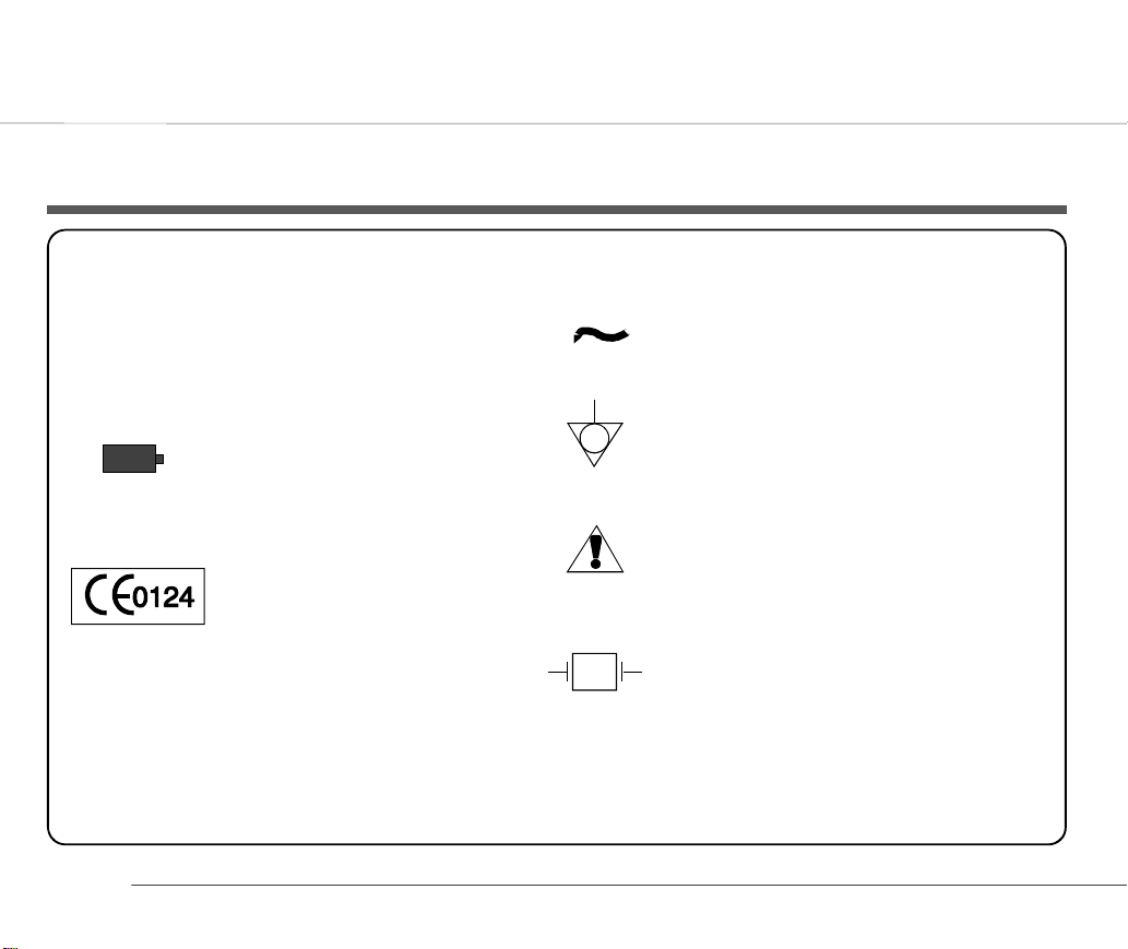
List of Symbols
applications. Note: The paddles indicate
that the equipment is defibrillator proof
Mains connected
Battery operation
(Flashes when battery
capacity limited.
93/42/EEC Medical Devices:
0124 `Notified Body` DEKRA AG
2
Potential Equalisation
(common ground)
Attention - General warning sign see accompanying documentation
Type CF equipment - safe for internal
♥
Page 13

AT-2plus 6-Channel ECG Unit - USER GUIDE
Modes of Operation................................................. 4
Automatic Mode.................................................................. 4
Manual Mode .....................................................................4
Automatic Mode ...................................................... 5
Manual Mode .......................................................... 6
Patient Cable Connections ...................................... 8
Standard Leads ..................................................................9
Location & Power ................................................... 10
Location ............................................................................. 10
Power Supply .....................................................................10
Switching On and Off .............................................. 11
Potential Equalisation .........................................................11
Keyboard ................................................................. 12
LCD Screen.............................................................. 14
Settings .................................................................... 15
Default Settings................................................................... 17
Language - American and Standard English ...................... 18
User Identification .............................................................. 18
Filters ................................................................................. 19
Baseline Filter ....................................................................19
Mains Filter ........................................................................19
Myogram Filter ..................................................................20
Defining Lead Sequence & Printout ....................................21
Acoustic QRS Indication .....................................................22
Time / Date ......................................................................... 22
Automatic Mode (ECG) Settings..............................23
Average Cycles ................................................................... 24
Measurements and Markings (i version only) .................... 25
Interpretation (i version only)............................................. 26
Interpretation Settings (i version only)................................ 26
Selecting Rhythm Leads ......................................................27
Memory and Data Transmission Option ..................28
Safety Notices .....................................................................28
Auto Storage and Auto Erase.............................................. 28
Manual Storage .................................................................. 29
Displaying Memory Files ................................................... 29
Reading and Printing a Stored File ..................................... 29
Erasing Memory Files ........................................................ 29
Memory and Data Transmission Option ..................30
Transmitting Stored Files ................................................... 30
Transmission Settings......................................................... 30
Line Transmission .............................................................. 31
Modem Transmission ......................................................... 31
Care & Maintenance ................................................33
Self-test ............................................................................... 33
12 Monthly Check............................................................... 33
Cleaning the Casing ........................................................... 33
Cleaning the Patient Cable.................................................. 34
Cleaning the Thermal Print Head .......................................34
Replacing the Recording Paper ...............................35
Thermal Paper Handling ................................................... 36
Fault Diagnosis ........................................................37
Technical Data .........................................................39
Available Configurations ....................................................41
3
Page 14

Modes of Operation
Automatic Mode
Automatic Mode provides a printout giving 10 seconds of ECG
recording of all 12 leads with a choice of 2 different formats.
The following can be programmed freely for each of the 2 formats
before recording:
• Lead Format
• Chart Speed
• With the optional interpretation program installed it is also
possible to select the measurement table, average cycles
with optional markings and interpretation statements for
the printout.
For further information see paragraph `Settings for Automatic
Mode`.
Manual Mode
Manual Mode provides a real time printout of 6 leads that are
selected and indicated on the screen.
The following can be freely selected before or during recording:
• Lead Group
• Chart Speed
• Sensitivity
• Myogram Filter
For further information see paragraph `ECG Recording in Manual
Mode` following.
4
Page 15
Automatic Mode
AT-2plus 6-Channel ECG Unit - USER GUIDE
In automatic mode , a full 12-lead ECG is printed in one of two
predefined formats with a sensitivity of 10 mm/mV. These two
formats are selected by the user to suit his specific needs and
requirements.
AUTO
When the AUTO SENSITIVITY key
recording in automatic mode, the unit detects very large waveform
amplitudes and sets the sensitivity for the extremity and/or precordial
leads to 5 mm/mV to reduce the overlapping of traces. An `A` on the
bottom line of the LCD indicates that Auto sensitivity is set.
3
is pressed before
To start the automatic ECG recording in
Format 1, press the AUTO key:
AUTO PRINT
To start the automatic recording in the
second format, press the ALT key followed
by the AUTO key:
ALT
+
AUTO PRINT
The printout gives the following:
• ECG recording of all leads in either Standard or Cabrera
format according to selection
• Sensitivity
• Heart Rate
• Speed
• Filter Settings
• Time and Date
• Interpretation statements
• Average Cycles
• Intervals
• Axis
• Sokolow Index (ECG index for hypertrophy)
• Detailed Measurement Table
To obtain an extra printout of the ECG recording in
Format 1, simply press the COPY key
To obtain an extra printout of the second format, press the ALT key
followed by the COPY key
The Auto mode settings for the two formats are detailed in the
paragraph entitled `Settings for Automatic Mode` later in this book
ALT
+
COPY
COPY
5
Page 16
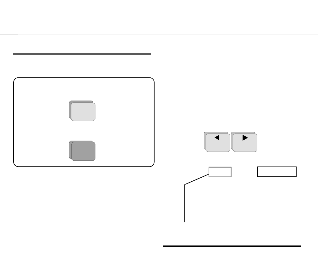
Manual Mode
Manual mode provides a direct printout of the real-time ECG with
full control of parameter selection.
To start the manual recording of a real-time
ECG, press the MANUAL Printout key
MAN
PRINT
To stop the manual recording (printout)
press the STOP key
STOP
6
The printout provides you with the following:
• Six (selected) leads with lead identification.
• On the lower edge, the chart speed, user identification and
filter settings (if on).
• At the top, the heart rate as current average of 4 beats, trace
sensitivity, and the time and date
The following can be freely chosen during or before the recording:
Lead Group by means of the LEAD FORWARD and LEAD
BACKWARD key
1
The following lead groups are selectable:
• I, II, III aVR, aVL, aVF
(Cabrera: aVL, I, -aVR / II, aVF, III)
• V1, V2, V3 / V4, V5, V6
• II, aVF, III / V2, V4, V5
• V4, V5, V6 / V7, V8, V9
Note: The LCD only displays three leads at one time. When the
lead forward or lead backward key is pressed, the following
/preceding three lead group is displayed
2
Page 17

Manual Mode
AT-2plus 6-Channel ECG Unit - USER GUIDE
Chart Speed Select speed 5, 10, 25 or 50mm/s by means of
the SPEED keys:
5/10
7
Notes: Key 7 is a toggle key -press once and 5 is selected,
press a second time and 10mm/s is selected.
When the 25 or 50mm/s key is pressed, the
same speed is set on both the screen and the
(manual) printout. When 5 or 10 mm/s is
selected, this affects the manual printout speed
only.
Sensitivity Select 5, 10 or 20 mm/mV by means of the
SENSITIVITY keys:
5
4
25
8
10
5
50
9
20
6
Myogram Filter Switch the filter ON or OFF with the FILTER
key:
FILTER
`FILTER` is displayed on the bottom line of the
LCD when the filter is switched on.
Recentering To re-centre the ECG traces, press the 1mV key
1mV
0
WARNING: AFTER HEAVY ARTEFACTS OR LEAD OFF , THE
INDICATION OF THE HEART RATE MAY NOT
BE RELIABLE.
7
Page 18

Patient Cable Connections
The accessory kit of the electrocardiograph includes a 10-lead patient
cable. This cable is plugged into the patient cable socket on the
right-hand side of the unit and secured with the two screws.
The AT-2plus is CF rated. The patient connection is fully isolated
and defibrillation protected. Protection against defibrillation voltage
is however only ensured, if the original WELCH ALLYN SCHILLER
patient cable (Part-no. 80130-0000) is used. Make sure that during
ECG recording neither the patient nor the conducting parts of the
patient connection or the electrodes (including the neutral electrode)
come into contact with other persons or conducting objects (even if
these are earthed).
The quality of the ECG is dependent on the preparation and the
resistance between the skin and the electrode. To ensure a good
quality ECG and minimise the skin/electrode resistance, remember
the following points:
1. Ensure that the patient is warm and relaxed.
2. Shave electrode area before cleaning.
3. Thoroughly clean the area with alcohol.
4. Place the C4 electrode first - in the fifth
intercostal space on midclavicular line.
Then place:
• C1 in fourth intercostal space at the right
sternal border
• C2 in fourth intercostal space at the left
sternal border
• C3 between, and equidistant to, C4 and C2
• C6 on left midaxillary line on the same level
as C4
• C5 between, and equidistant to, C4 and C6
The electrode placements shown on the following page are labelled
with the colors according to IEC requirements. The equivalent AHA
colors are given on the table opposite.
8
Page 19

AT-2plus 6-Channel ECG Unit - USER GUIDE
Patient Cable Connections
IEC AHA
N Black RL Green
R Red RA White
C1 White/Red V1 Brown/Red
C2 White/Yellow V2 Brown/Yellow
C3 White/Green V3 Brown/Green
C4 White/Brown V4 Brown/Blue
C5 White/Black V5 Brown/Orange
C6 White/Violet V6 Brown/Violet
L Yellow LA Black
F Green LL Red
Standard Leads
9
Page 20

Location & Power
Location
Do not keep or operate the apparatus in a wet, moist, or dusty
environment. Also, avoid exposure to direct sunlight or heat from
other sources. Do not allow the unit to come into contact with acidic
vapours or liquids, as such contact may cause irreparable damage.
The unit should not be placed near X-ray or diathermy units, large
transformers or motors. The unit must be placed on a flat surface
and must not be operated in areas where there is any danger of
explosion.
Power Supply
The mains connection is on the rear of the unit. The mains indicator
lamp on the keyboard is always lit when the unit is connected to the
mains supply. The unit can either be operated from the mains supply
or from the built-in rechargeable battery. The power source is indicted
on the top line of the LCD.
Power Indication
HR: 76/min
Wed 20-AUG-96 18:20:21
R L F C1 C2
C3 C4 C5 C6
When mains is connected a mains symbol is
displayed (as shown above). When the unit is
running on battery power a battery symbol is
displayed:
When battery capacity is limited, the battery
symbol flashes on and off.
To recharge the battery, connect the apparatus to the mains supply
by means of the supplied power cable. A totally discharged battery
needs less than 15 hours to be fully recharged (60% in less than 3
hours, 90% in less than 7 hours). A fully charged battery gives
approximately 4 hours of normal use. The unit can remain connected
to the mains supply without any danger of damage to either the
battery or the unit.
10
Page 21

Switching On and Off
AT-2plus 6-Channel ECG Unit - USER GUIDE
The SCHILLER AT-2plus is switched on with the green ON key
ON
and off by means of the red OFF key
OFF
The unit is automatically switched off after 5 minutes (30 seconds if
battery capacity is limited) if no key is pressed and the patient cable
is not connected.
Potential Equalisation
If the AT-2plus is used in conjunction with other patient connected
equipment, we recommend that the potential equalisation stud (on
the rear of the unit) is connected to the hospital/ building common
ground using the yellow/green earth cable. When working from an
emergency vehicle, the vehicle common ground can be used.
11
Page 22

Keyboard
12 13 14 15 16 17
1 2 3 4 5 6 7 8 9 10 11
PATIENT
DATA
COPY FILTER
MAN
STOP
PRINT
AUTO PRINT
1 2
AUTO45
3
5106
2075/10
8259500
Q W E R T Y U I O P
A S D F G H J K L
Z X C V B N M / :. ?
1mV(QRS
)
'
ü é
~
^
ö ç ä ø
`
è å
DELETE
ALT
ENTER
SPACE
OFF ON
12
Page 23

Keyboard
1 Print extra copy - of Auto mode recording currently in memory. Press
the ALT key first followed by this key to obtain a copy in Auto format
2.
2 Display/enter patient data. When the patient data is displayed, pressing
this key again returns to the ECG. Use the up/down arrows to go to the
next data entry field.
In the `Born` (date of birth field), only the patients year of birth need be
entered (2 or 4 digits), - patient age is calculated to the nearest year. To
calculate the age precisely, the day, month and year (2 or 4 digits) must
be entered.
3 Myogram filter ON / OFF. The cutoff frequency can be defined and is
detailed in `Settings`.
4. The top figures on the number keys designated > and < changes the
lead group displayed on the screen.
5. Auto sensitivity key - automatically sets the ECG printout sensitivity
( in AUTO mode only) to the best setting for the signal strength (5mm/
mV or 10mm/mV)
6. The top figures on the number keys designated 5, 10, and 20 set the
sensitivity of the ECG both on the screen and on the (manual) printout.
The sensitivity is 5, 10 or 20 mm / mV.
7. The top figures on the number keys designated 5/10, 25, and 50 set the
speed of the ECG both on the screen and on the (manual) printout.
The speed on the screen can only be set to 25 or 50 mm / s. The speed
of the manual printout can be 5, 10, 25 or 50 mm/s. The 5 & 10 mm/s
settings are both on the same key which toggles the two speeds.
AT-2plus 6-Channel ECG Unit - USER GUIDE
8. The top character `QRS` toggles the QRS beeper ON/ OFF
9. Delete last typed character.
10. Switch the unit OFF.
11. Switch the unit ON.
12. Manual mode recording - start continuous printout of ECG until STOP key pressed
13. Auto Mode recording (in Auto mode 1). Press ALT followed by
the AUTO key for auto mode 2.
14. STOP printout / confirm (new) setting
15. ALT key - key for initiation of setups and selection of second
format for printout and auto mode recording
16. In ECG mode use the UP/DOWN arrows to adjust screen
contrast.
When entering patient data use the LEFT/RIGHT arrow keys
to move cursor in data field. Use the UP/DOWN arrow keys to
go up/down to the next data entry
17. Mains Indicator - lit when mains connected.
Second letters on the keyboard - è, é, ç, ø are reached by holding the
ALT key pressed before the letter key. Accents on a letter e.g. ô, ñ etc.
are reached by pressing the shift key (é) and the accent required (one
of the group of four keys situated to the left of the ALT key), and then
the letter. In addition the following special characters are available:
Key combination: é + 1 2 3 4 5 6 7 8 9 0
Character ! @ # $ % & / * " =
13
Page 24

LCD Screen
1 2 3 4
HR: 76/min
I II III FILTER A 10mm/mV 25 mm/s
14
Wed 20-AUG-96 18:20:21
Check Paper
5 6 7 8 9
ALT
R L F C1 C2
C3 C4 C5 C6
1. Current Heart Rate (averaged over 4 beats and refreshed
every 2 seconds). The HR is also given on a manual printout.
Note that with an auto mode printout the HR is averaged
over the full 10 seconds of the recording.
2. Top line - Current Day, Date and Time
Bottom Line - System messages
3. Top Line - Current power source - mains or battery. When
battery capacity is limited the battery symbol flashes.
Bottom line - `ALT` in this box indicates that the ALT key
has been pressed.
4. Electrode connections - when a lead flashes it indicates that
the electrode resistance is too high. The electrode must be
reapplied
5. Lead indication (leads currently displayed on the screen).
Change the lead group with the keys `1` and `2`.
6. Myogram Filter indication - `Filter` = filter ON; no
indication = filter OFF. Switch the filter on or off with the
Filter key.
7. An `A` in this box indicates that automatic sensitivity is
selected (auto mode printout only). Switch automatic
sensitivity on or off with key `3`.
8. Sensitivity - 5, 10 or 20 mm/mV. Change the sensitivity
with the keys `4`, `5`, and `6`.
9. Speed - 25 or 50 mm/s. Change the speed with the keys `8`,
and `9`.
Page 25

Settings
AT-2plus 6-Channel ECG Unit - USER GUIDE
Each parameter is set by means of a code. This code comprises a
combination of keys starting with the ALT key followed by two or
three numbers. The setting is confirmed with the STOP key. As
soon as the ALT key is pressed, the keyboard is dedicated to the
programming function.
When the ALT key is pressed `ALT` appears on the LCD (see previous
page). The Alternative (ALT) function is only active for 4 seconds. If
a programming key is not pressed within 4 seconds, the unit reverts
to standard mode. The ALT key must again be pressed to activate
the programming mode
The setting is remembered and the keyboard released for other
functions when the STOP key is pressed. Once a setting has been
confirmed, it is stored in the memory even when the unit is switched
off.
On the following pages the programmable parameters and the
programming sequences are described in detail.
15
Page 26

Settings
The defined formats and settings that are set for your unit can be
checked as follows:
Setup Printout
Entry Key Sequence Result
ALT 0 1 1
A printout of the defined settings will be produced and gives the
following information, depending on the installed software:
Unit designation Software option installed (i = Interpretation)
and Software version
Serial number Serial number of the unit
Leads Standard (S) or Cabrera (C)
ECG Format Long (ooo), Short (o) or Suppressed (-)
MECG Average cycles as defined in auto ECG recording
setup (e.g. 4 * 3 (25 mm/s) + 2)
Measurements Enabled (+) or Suppressed (-)
Printout of
programmed Settings
Marks Enabled (+) or Suppressed (-)
Interpretation Enabled (+) or Suppressed (-)
Selected Rhythm leads Leads selected for R1, R2 resp.
Automatic Centering Enabled (+) or Suppressed (-)
Printout of signals Sequential or Simultaneous
Baseline Filter 0.05, 0.15 or 0.30 Hz
Mains Filter 50, 60 Hz or OFF (-)
Myogram Filter 25 or 35 Hz, ON (+) or OFF (-)
Memory & Transmission Auto. Storage: ON(+) or OFF(-)
Auto. delete: delete all recordings
after transmission
ON(+) or OFF(-)
Baud rate: 115200, 57600,
38400, 28800,
14400 or 9600
Transmission: Line or Modem
16
Page 27

Settings
Interpretation settings: N/A:+/- ‘normal/abnormal’ is
written (+) or suppressed
(-)
U:+/- ‘unconfirmed report’ is
written (+) or suppressed
(-)
A30:+/- patient age is assumed to be
< 30 (-) or >30 (+)
S: +/- low (-) or high (+)
sensitivity
Default Settings
To reset the unit to the basic default settings, proceed as follows:
Reset to Default Settings
Entry Key Sequence Result
ALT 0 6 6
Reset to default
settings
AT-2plus 6-Channel ECG Unit - USER GUIDE
SETTINGS STANDARD
LANGUAGE AS SET AS SET
LEADS STANDARD (S) STANDARD (S)
AUTO FORMAT 1
AUTO FORMAT 2
RHYTHM LEADS V1 V1, II
AUTOM.
CENTERING
PRINTOUT OF
SIGNALS
BASELINE FILTER
SETTING
MAINS FILTER
SETTINGS
MYOGRAM
FILTER SETTING
MEMORY AND
SERIAL
COMMUNICATION INTERFACE
OPTION
MEMORY
INTERPRETATION
SETTINGS
ECG: 25MM/S,
SHORT (O)
ECG: 25MM/S,
LONG (OOO)
ENABLED (+) ENABLED (+)
SEQUENTIAL SEQUENTIAL
0.05HZ 0.05HZ
50HZ (60HZ) 50HZ (60HZ)
35HZ, OFF 35HZ, OFF
BAUD RATE 115200
BPS
AUTO STORAGE
ON (+)
AUTO DELETETION
OFF (-)
TRANS. MODE:
LINE
AUTO SAVE
ENABLED (+)
AUTO ERASE
DISABLED (-)
WITH
INTERPRETATION
ECG : 25MM/S,
SHORT (O)
MECG: 2*6
(50MM/S + 1)
MEASUREMENTS:
SUPRESSED (-)
INTERPRETATION:
ENABLED (+)
MARKS: ENABLED
(+)
ECG : 25MM/S,
LONG (OOO)
MECG: NONE
MEASUREMENTS:
SUPRESSED (-)
INTERPRETATION:
DISABLED (-)
MARKS: ENABLED
(+)
BAUD RATE 115200
BPS
AUTO STORAGE
ON (+)
AUTO DELETETION
OFF (-)
TRANS. MODE:
LINE
AUTO SAVE
ENABLED (+)
AUTO ERASE
DISABLED (-)
N/A: SUPRESSED (-)
U: ENABLED (+)
A30: UNDER
THIRTY (-)
S: LOW (-)
17
Page 28

Settings
Language - American and Standard English
The unit language is set by the software and cannot be changed.
However, when English is installed it is possible to select American
English or Standard English. The difference is as follows:
American Standard English
measurements in inches measurements in centimetres
temperature in Fahrenheit temperature in degrees centigrade.
mains filter setting - 60Hz mains filter setting - 50Hz
date order mm-dd-yy date order dd-mm-yy
Additionally, when American is set, further race settings are given
and Spiro diagnosis is based on ITS recommendations - see handbook.
The default language is Standard English.
Define American or Standard English as follows:
1mV
ALT
For American English
ALT
For Standard English
0
1mV
0
2
2 2
10
5
18
User Identification
The user identification is printed on all recordings. The user ID can
be the department, doctor or hospital etc. Enter the user ID as
follows:
Press the ALT key followed by key 9, 3, 3
50
ALT
The user entry field is displayed on the LCD. Enter up to 30
characters via the keyboard.
Confirm the new user ID by pressing the ENTER key.
Note: If the unit is reset to the default settings (see previous page),
+
9
the user identification must be re-entered
AUTO
+
3
AUTO
+
3
Page 29

Settings
Filters
AT-2plus 6-Channel ECG Unit - USER GUIDE
There are three different filters which can be set individually as
follows:
• Baseline filter
• Mains filter
• Myogram filter
Baseline Filter
The digital Baseline filter suppresses excessive baseline drifts.
The setting options are as follows:
Baseline Filter
Entry Key
Sequence
ALT 5
Confirm the selection by pressing
Filter Setting Confirm
0.05 Hz
0
(default)
1 0.15 Hz
3 0.30 Hz
Press
STOP key
STOP
Note: The set value is the lower limit of the frequency range and is
normally set to 0.05 Hz. The settings 0.15 and 0.30 Hz
should only be used when absolutely necessary, as the
possibility exists that they could affect the original ECG signal,
especially the ST segments.
Mains Filter
The Mains filter is an adaptive digital interference filter designed
to suppress AC interference without attenuating or distorting the
ECG.
Set the mains filter in accordance with the frequency of your local
mains supply as follows:
Mains Filter
Entry Key
Sequence
ALT 8
Filter Setting Confirm
Mains Filter 50
5
6
9
Hz
Mains Filter 60
Hz
Mains Filter
Off
Press
STOP key
19
Page 30

Settings
Myogram Filter
The Myogram filter suppresses disturbances caused by strong
muscle tremor. The set value will be the new upper limit of the
frequency range as soon as the FILTER key is pressed on or
programmed as default when the unit is switched on. When the
Myogram filter is on `Filter` is displayed on the bottom line of the
LCD.
Myogram Filter
Entry Key
Sequence
2 Myogram Filter 25 Hz
3 Myogram Filter 35 Hz
ALT 8
Confirm the selection by pressing the STOP KEY
1
8
Setting Confirm
Myogram Filter active
when the unit is first
switched on (marked
on printout with +)
Myogram Filter off
when the unit is first
switched on (marked
on printout with -)
Press
STOP key
The myogram filter is switched on and off manually with the FILTER
KEY
Note: An ECG recorded in auto mode is stored unfiltered. It is
FILTER
therefore possible to print the stored ECG either with or
without passing the myogram filter. Filter ON is indicated in
the bottom information line of the LCD. When the FILTER
key is pressed again, the filter is switched off and the `Filter`
indication on the bottom information line of the LCD is
removed. The cutoff frequency of the myogram filter is set to
either 25 or 35 Hz.
20
Page 31

Settings
AT-2plus 6-Channel ECG Unit - USER GUIDE
Defining Lead Sequence & Printout
The required settings can be selected as follows:
Sequences, Print & Auto-centering
Entry Key
Sequence
1
2 Cabrera Lead Sequence
ALT 7
Confirm the selection by pressing STOP
3 Simultaneous Print
4 Sequential Print
5 Auto-centering ON
6 Auto-centering OFF
Definition Confirm
Standard Lead
Sequence
Press
STOP key
STOP
The selectable printout forms are:
Simultaneous All ECG leads are printed in the same time
segment (in automatic mode only).
Sequential Each group is a contiguous time segment of
approximately 2.5 or 5 seconds (in automatic
mode only).
Auto-Centering ON All ECG traces are centred dynamically for
optimal use of paper width.
Auto-Centering OFF ECG traces are set to a fixed baseline
position and may possibly overlap.
The Standard and Cabrera lead groups available for the AT-2plus
are:
Lead Groups
Standard Cabrera
I V1 II V4 aVL V1 II V4
II V2 aVF V5 I V2 aVF V5
III V3 III V6 -aVR V3 III V6
aVR V4 V2 V7 II V4 V2 V7
aVL V5 V4 V8 aVF V5 V4 V8
aVF V6 V5 V9 III V6 V5 V9
21
Page 32

Settings
Acoustic QRS Indication
The acoustic QRS beep can be switched on or off at any time by
pressing the QRS key
QRS
(
Time / Date
The required settings can be selected as follows:
Setting the Time and Date
Key Sequence Enter Data Confirmation
Time
ALT 9 1 1 HHMMSS beep
Date
ALT 9 2 2 DDMMYY beep
Seasonal Time Variation
Key Sequence
Wintertime to
Summertime (+1Hr)
Summertime to
Wintertime (-1Hr)
ALT 9 4 4
ALT 9 5 5
22
Page 33

Automatic Mode (ECG) Settings
AT-2plus 6-Channel ECG Unit - USER GUIDE
Two separate Auto formats can be defined for the AT-2plus. When
defining auto format 1 the key sequence ALT `1` precedes the setting.
When defining auto format 2 the key sequence ALT `2` precedes the
setting.
Automatic ECG Format
Entry Key
Sequence
1
ALT
2
The automatic mode formats are detailed on the following pages.
The ECG format is set as follows:
Setup Format
Commence Setup for
Auto format 1
Commence Setup for
Auto format 2
ECG Format
Entry Key Sequence Printout Confirm
1page x 12 leads at
ALT 1 or 2 1
1
2
5 No leads printed
6
7
8 Chart Speed 25mm/s
9 Chart Speed 50mm/s
0
25mm/s
One page with the first
8 leads printed for 5s
and the last 4 leads
printed for 10s
Leads are printed in
short form (1 sheet)
Leads are printed in
long form (2 sheets)
Leads are printed in
format 4 * 3(25mm/s)
+ 1 rhythm(25mm/s)
Press
STOP key
23
Page 34

Automatic Mode (ECG) Settings
Average Cycles
The Average cycles are defined as follows:
Note: Lead selection for the rhythm lead(s) are defined on page 27
Average Cycles (interpretation option only)
Entry Key Sequence Printout Confirm
No average lead cycles
5
6
ALT 1 or 2 2
7
8
are printed
4 x 3 (25 mm/s) + 2
rhythm leads
(25mm/s). The average
complexes are printed
in 4 groups of three
leads at a chart speed of
25mm/s
4 x 3 (50 mm/s) + 2
rhythm leads
(25mm/s). The average
complexes are printed
in 4 groups of three
leads at a chart speed of
50mm/s
2 x 6 (50 mm/s) + 2
rhythm leads
(25mm/s). The average
complexes are printed
in 2 groups of six leads
at a chart speed of
50mm/s
Press
STOP key
24
Page 35

Automatic Mode (ECG) Settings
Measurements and Markings (i version only)
AT-2plus 6-Channel ECG Unit - USER GUIDE
Measurements (Interpretation Option Only)
Entry Key Sequence Printout Confirm
To define the measurements and markings proceed as follows:
ALT 1 or 2 3
Detailed table of
measurement results
omitted - however, the
5
values of electrical
axes, intervals, and
heart rate are not
suppressed.
Detailed table of
6
measurement results is
printed
Referenece markings are
7
8
omitted
Reference markings
(beginning and end of
P wave and QRS, and
end of T wave) are
added to the ECG
average cycles
Press
STOP key
25
Page 36

Automatic Mode (ECG) Settings
Interpretation (i version only)
To print or suppress interpretation statements on the printout
proceed as follows:
Interpretation (Interpretation Option Only)
Entry Key Sequence Printout Confirm
Interpretation is
ALT 1 or 2 4
5
6 Interpretation is printed
Confirm the selection by pressing
Full details of the interpretation option are given in the WELCH
ALLYN SCHILLER ECG Measurement and Interpretation booklet
(art. No. 2.510 179).
omitted
STOP
Press
STOP key
26
Interpretation Settings (i version only)
The interpretation settings enable the user to determine whether or
not certain comments will be added to the interpretation statements
on the ECG printout. Furthermore, the patient’s age can be defined
(<30 or >30) and if low or high sensitivity should be applied. Low
sensitivity will suppress certain nonspecific ECG diagnosis; this
may be advisable when carrying out ECGs for screening.
Interpretation Settings
Entry Key
Sequence
"Normal" / "Abnormal" is not
1
"Normal" / "Abnormal" is
2
"Unconfirmed report" is not
3
ALT 6
Note: The `Patient age assumed to be..` setting is only applicable
4 "Unconfirmed report" is printed
Patient age assummed to be <
5
Patient age assummed to be >
6
7 Low sensitivity
8 High sensitivity
when patient data has not been entered.
Setting Confirm
printed
printed
printed
Press
STOP key
30
30
Page 37

AT-2plus 6-Channel ECG Unit - USER GUIDE
Automatic Mode Settings
Selecting Rhythm Leads
The rhythm leads are printed out as defined. Two separate rhythm
leads can be selected. The following formats can be set:
Rhythm Leads (interpretation
Entry Key
Sequence
ALT
The 2 rhythm leads are defined as follows:
option only)
Setup Format
Define Rhythm lead
3
Define Rhythm lead
4
one
two
Extremity Leads
Entry Key Sequence Lead Confirm
ALT 3 or 4 8
Precordial Leads
Entry Key Sequence Lead Confirm
ALT 3 or 4 9
Confirm the selection by pressing
1 I
2 II
3 III
4 aVR
5 aVL
6 aVF
1 V1
2 V2
3 V3
4 V4
5 V5
6 V6
STOP
Press
STOP key
Press STOP
key
.
27
Page 38

Memory and Data Transmission Option
Safety Notices
WHEN NON-MEDICAL DEVICES ARE CONNECTED TO THE
RS-232 INTERFACE ENSURE THAT BOTH UNITS ARE
SECURELY CONNECTED TO THE SAME EARTH POTENTIAL.
WHEN OPERATING THE UNIT ON BATTERY AND
SIMULTANEOUSLY USING NON-MEDICAL DEVICES, THE RS232 INTERFACE MUST BE FULLY ISOLATED.
AN EXTERNAL DEVICE MUST ONLY BE CONNECTED USING
THE ORIGINAL SCHLLER INTERFACE CABLE ASSEMBLY.
The memory option allows approximately 45 recordings (dependent
on size and parameters specified when the recording was taken) to
be stored and transmitted over the RS-232 interface. When no more
recordings can be stored the message `MEMORY FULL` is
displayed. Old recordings must be deleted or transmitted before
further recordings can be stored. A number of memory settings can
be made as follows:
Note: At the time of print it is not possible to read or to delete
individual stored recordings.
Auto Storage and Auto Erase
Memory Setup
Entry Key Sequence Save Mode
0 Auto save off
ALT 0 5
With `auto save on`, all auto mode recordings, will be automatically
stored on completion.
With `auto erase on`, all stored recordings are erased after sending
over the RS-232 interface.
1 Auto save on
2 Auto erase off
3 Auto erase on
28
Page 39

AT-2plus 6-Channel ECG Unit - USER GUIDE
Memory and Data Transmission Option
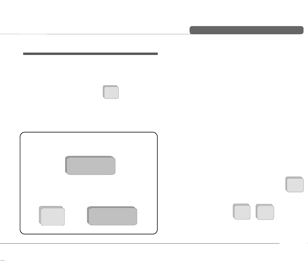
Manual Storage
When auto save is set to off, the following message is displayed
after an auto mode ECG.
STORE CURRENT RECORDING?
Use the arrow keys to select yes or no and press the ENTER key.
When YES is selected the message `STORING` appears in the message box (under the date and time box), during the storage process.
To store the current recording at any time, press the ALT key followed by the key `S`.
Displaying Memory Files
To display the contents of the memory press the ALT key followed
by the key 'M'.
YES / NO
ALT
ALT
+ `S`
+ `M`
Reading and Printing a Stored File
° Enter the memory mode - press the ALT key followed
by the key 'M'.
+ `M`
ALT
° Select an ECG using the cursor keys.
⇐⇑⇒⇓
° Read the selected ECG - press and hold the ALT key
and then press key `R `.
and `R`
ALT
° Obtain a printout - press Copy key.
COPY
Erasing Memory Files
To erase the contents of the memory (delete all files), press and hold
the ALT key and then press key `E `.
and `E`
ALT
ERASE ALL?
YES / NO
When YES is selected the message `ERASING` appears in the message
box (under the date and time box), during the erasing process.
29
Page 40

Memory and Data Transmission Option
Transmitting Stored Files
The contents of the memory can be transmitted to the SEMA-200
data management program, either directly using the RS-232 connector
of the computer, or over the telephone system. Sending directly is
termed LINE transmission; sending over the telephone system
requires a modem and this form of sending is termed MODEM.
Transmission Settings
The speed settings options for the AT-2plus are as follows:
Serial Communication Interface
Entry Key Sequence
ALT 0 9 1
Transmission
Speed
0 115200
1 57600
2 38400
3 28800
4 19200
5 14400
6 9600
The mode of transmission is as follows:
Communication Mode
Entry Key Sequence Mode
ALT 0 9 2
Enter the telephone number as follows:
Enter Telephone Number
Entry Key Sequence Mode
ALT 0 9 3 2 enter number
Note: The modem initialisation commands, entered when the
modem is first connected, are also entered in this screen.
1 line
2 modem
30
Page 41

Memory and Data Transmission Option
The transmit function (over line or modem), transmits all recordings
currently in memory, to the selected destination.
AT-2plus 6-Channel ECG Unit - USER GUIDE
Line Transmission
To transmit recordings over line, proceed as follows:
° Set Communication mode to LINE - key sequence:
ALT
° Connect the cable assembly (optional accessory, art.
No. 2.310 159) between the RS-232 connector on the
AT-2plus and the COM interface of your Computer.
° Ensure that the SEMA communication program
(SEMACOMM) is active on the computer (see SEMA
handbook).
° Enter the memory mode - press the ALT key followed
by the key 'M'.
° Press and hold the ALT key and then press key `T `.
1mV
0
ALT
ALT
50
9
+ `M`
and `T`
2 1
Modem Transmission
To transmit recordings over the telephone network, proceed as follows
° Set Communication mode to MODEM - key sequence:
ALT
° Enter Phone number and modem initilisation codes
ALT
the following is displayed:
1mV
0
1mV
0
Phone No.
T, 0417608787
Modem Initialization
ATBOL1VOQ0E0S0=0
50
9
50
9
2 2
AUTO
3
2
31
Page 42

Memory and Data Transmission Option
Enter the telephone number preceded by `P` or `T` (tone or
pulse).
A comma `,` gives a one second pause in dialing - this may
be necessary if for example, an outside line is required.
Enter the modem initialisation codes. Full details will be
found in the user guide for your modem. However, the modem initialisation must contain at the minimum, the following commands with the prefix `AT`.
`Q0`- modem sends response
`V0`- numerical response codes
`E0`- no command echo
The standard modem initialisation code is:
ATB0L1V0Q0E0S0=0
Press the patient key to store settings.
Connect the modem cable assembly (supplied with mo-
dem) between the RS-232 connector on the AT-2plus and
the modem
Ensure that the SEMA communication program
(SEMACOMM) is active on the computer (see SEMA handbook).
° Enter the memory mode - press the ALT key followed
by the key 'M'.
+ `M`
ALT
° Press and hold the ALT key and then press key `T `.
and `T`
ALT
The message `TRANSMITTING` appears while the unit
is sending in the message box (under the date and time box)
If a transmission error occurs the message `Tx ERROR` is
displayed.
Check all settings in the SEMACOMM program (baud rate;
parity - none; stop bit - 2; time between blocks, records 100ms).
Check that the transmission speed is the same in both the
AT-2plus and the SEMACOMM program.
To stop transmission press and hold the ALT key and then
press key `Q`.
and `Q`
ALT
32
Page 43

Care & Maintenance
Self-test
Initiate a self-test of the AT-2plus as follows:
AT-2plus 6-Channel ECG Unit - USER GUIDE
Self Test
Entry Key Sequence Action
ALT 0 3 3
A table giving information for the service staff is displayed.
To obtain a printout press `P` when the table is displayed. Exit this
screen by pressing the ENTER key.
Service
Data
Displayed
12 Monthly Check
The unit should undergo a technical safety check every 12 months.
This safety check should include the following:
• Visual inspection of the unit and cables.
• Electrical safety tests according to IEC 601-1 and IEC 6012-25.
• Functional tests according to the Service Handbook.
The test results must be documented.
Cleaning the Casing
CAUTION: SWITCH THE UNIT OFF BEFORE
CLEANING AND DISCONNECT THE MAINS. DO NOT,
UNDER ANY CIRCUMSTANCES, IMMERSE THE
APPARATUS INTO A CLEANING LIQUID OR STERILIZE
WITH HOT WATER, STEAM, OR AIR.
The casing of the AT-2plus can be cleaned with a soft damp cloth on
the surface only. Where necessary a domestic non-caustic cleaner
can be used for grease and finger marks.
33
Page 44

Care & Maintenance
Cleaning the Patient Cable
ALIGN THE LEADS IN SUCH A W AY AS TO PREVENT ANYONE
STUMBLING OVER THEM OR ANY DAMAGE CAUSED BY THE
WHEELS OF INSTRUMENT TROLLEYS.
The patient cable should not be exposed to excessive mechanical
stress. Whenever disconnecting the leads, hold the plugs and not the
cables. Store the leads in such a way as to prevent anyone stumbling
over them or any damage being caused by the wheels of instrument
trolleys.
The cable can be wiped with soapy water. Sterilization, if required,
should be done with gas only and not with steam. To disinfect, wipe
the cable with hospital standard disinfectant.
Cleaning the Thermal Print Head
If the printer is used a lot, a residue of printers ink ( from the grid on
the paper) can build up on the print head. This can cause the print
quality to deteriorate. We recommend therefore that every month
the print head is cleansed with alcohol as follows:
Remove the paper tray. The thermal printhead is found under the
paper tray release catch.
With a tissue dampened in alcohol, gently rub the printhead to
remove the ink residue. If the printhead is badly soiled, the colour of
the paper grid ink (i.e. red or green) will show on the tissue.
34
Page 45

AT-2plus 6-Channel ECG Unit - USER GUIDE
Replacing the Recording Paper
The recording paper must be replaced as soon as the end of the paper is indicated by a red stripe on the lower edge. After the indication first appears,
there are about 8 pages left. However, we recommend that the paper be replaced immediately. If no paper is left, the printing process is interrupted
and a warning is given on the screen. To replace the paper proceed as follows:
35
Page 46

Replacing the Recording Paper
• Place fingers under the retaining bar and
pull directly upwards. The paper tray cover
releases.
• Withdraw the cover from the unit. DO NOT
FORCE, THE PAPER TRAY COVER
RUNS FREELY OVER THE DEDICATED
RUNNERS.
• Remove any remaining paper from the
paper tray.
• Place a new paper pack into the paper tray
with the printed (grid) side facing upwards.
• Place the beginning of the paper over the
black paper roller on the paper tray cover.
• Return the paper tray cover in position and
press firmly until secure.
• Press the STOP key to transport the paper
to the start position.
WELCH ALLYN SCHILLER can only guarantee perfect
printouts when WELCH ALLYN SCHILLER original chart
paper or chart paper of the same quality is used.
Thermal Paper Handling
The thermal paper used in the AT-2plus requires slightly different
handling to normal paper as it can react with chemicals and to heat.
However, when the following points are remembered, the paper
will give reliable results:
The following points apply to both storage, and when archiving the
results.
1. Before use, keep the paper in its original cardboard cover.
Do not remove the cardboard cover until the paper is to be
used.
2. Store in a cool, dark and dry area.
3. Do not store near chemicals e.g. sterilisation liquids.
4. In particular do not store in a plastic cover.
5. Certain glues can react with the paper - do not attach the
printout onto a mounting sheet with glue.
36
Page 47

Fault Diagnosis
AT-2plus 6-Channel ECG Unit - USER GUIDE
Unit does not switch on, Blank Screen
Green mains indicator on?
No? Check mains supply.
Yes? Check contrast with the UP/DOWN cursors
keys
If mains is OK and the screen is still not lit:
Press the OFF key
Wait a few seconds and switch on again.
If the screen is still not lit: Call your local
WELCH ALLYN SCHILLER representative.
QRS traces overlap
Ensure that the automatic sensitivity reduction
is not switched off.
Reset signals to baseline - press the 1mV key
Check electrode contact
‘Noisy’ traces
Check electrode contact
Reapply electrodes
Ensure that the patient is relaxed and warm
Check all filter settings.
Activate Myogram filter - change cutoff
frequency
Ensure mains filter is correct for mains supply
No printout obtained after an auto mode recording
Ensure that paper is loaded.
Check Settings - ensure that at least one item is
selected for print after an auto ECG is recorded
Contact your local WELCH ALLYN SCHILLER
representative.
37
Page 48

Fault Diagnosis
Printout fades or is not clear
Ensure that fresh WELCH ALLYN SCHILLER
paper is installed.
Note that the thermal paper used for the AT2plus is heat and light sensitive. If is not stored
in its original seal, stored in high temperatures
or is simply old, print quality can deteriorate.
Ensure that the paper has been installed correctly
with the paper mark at the top.
Over a period of time, the printing ink from the
grid on the paper can form a film on the thermal
print head. Clean the thermal print head with a
clean cloth as described previously.
If the problem persists call your local WELCH
ALLYN SCHILLER representative.
38
No printout of interpretations statement or measurements
Check that the interpretation and measurement
options are enabled for the printout.
No key response, LCD locked
Switch off, and switch on again after a few
seconds
Page 49

Technical Data
AT-2plus 6-Channel ECG Unit - USER GUIDE
Technical data subject to change without notice.
Dimensions 400 x 330 x 100 mm
Weight 5.0 kg ( 5.35 kg with full paper tray)
Mains Supply 100 to 115 / 220 to 240 VAC, 50/60 Hz
Battery Built-in 12 V lead-acid battery (rechargeable)
Battery Capacity 4 hours normal use - 300 printouts
Power Consumption Recording: 40 VA max
Leads Standard / Cabrera
Paper Speed 5 / 10/ 25 / 50 mm/s (direct)
Sensitivity 5 /10 / 20 mm/mV, either automatically
adjusted or manually selected
Chart Paper Thermoreactive - Z-folded, 210 mm wide,
perforation 280 mm
Printing Process High-resolution thermal print head,
8 dots per mm / 200 dots per inch
(amplitude axis)
40 dots per mm / 1000 dots per inch
(time axis 25mm/s)
Recording Tracks 6 channels, positioned at optimal width on
200 mm, automatic baseline adjustment
Automatic Lead Programs
Printout of all 12 leads
Data Record: Listing of ECG recording data
Version i: ECG measurement results
(intervals, amplitudes, electrical axes),
Sokolow Index, average complexes with
optional measurement reference markings,
and interpretation.
ECG Storage: Circular input memory for 10 s, 12-lead
ECG.
Memory Option: Memory for c.45 ECG recordings with
transmission facilities over an RS-232
interface.
Frequency Range of Digital Recorder:
0 to 150 Hz (IEC)
0 to 150 Hz (AHA)
39
Page 50

Technical Data
ECG Amplifier: Simultaneous, synchronous registration of
all 9 active electrode signals (= 12 standard
leads)
Sampling frequency: 1000 Hz
Digital resolution: 5 µV
Dynamic range: ±9.5 mVAC
Max. electrode potential: ±300 mVDC
Time constant: 3.2 s
Frequency response: 0.05 to 150 Hz (-3
dB)
Input impedance:
>2.5MOhms at 10Hz
Myogram Filter (muscle tremor filter)
25 Hz or 35 Hz, programmable (not active
on averaged waveform). The stored ECGs
can be printed with or without filter.
Line Frequency Filter: Distortion-free suppression of
superimposed 50 or 60 Hz sinusoidal
interferences by means of an adaptive digital
filter.
Patient Input: Fully floating and isolated, defibrillation
protected.
Safety Standard: CF according to IEC and complying with
the following
RL 93/42/EEC
EN 60601-1:1990
IEC 601-1
IEC 601-2-25:1993
pr EN 1441:1994
EMC: CISPR 11: 1985, EN 55011: 1992
IEC 801-2: 1991
IEC 801-3: 1984
IEC 801-4: 1988
IEC 801-5:
Safety Class: I according to IEC 601-1 (with internal power
supply)
IIa according to RL 93/42/EEC, CE-0124
This device is not designed for outdoor use
(IP 20)
40
Page 51

Technical Data
Environmental Conditions:
Temperature, Operating: 10O to 40OC
Temperature, Storage: -10O to 50O C
Relative humidity: 25 to 95% (non
condensing)
Atmospheric pressure: 700 to 1060 hPa
Control Panel: Rubber keys
Technical data subject to change without notice.
Available Configurations
The AT-2plus is available in two versions:
Standard Version:Unit with ECG recording and printout
capabilities.
Version i: Unit with additional ECG Interpretation
program (including measurements).
AT-2plus 6-Channel ECG Unit - USER GUIDE
41
Page 52

42
 Loading...