

Page 1
Cardio Menu
Service Manual
6-Channel Electrocardiograph
Electrocardiographe à 6 canaux
i
Page 2
AT-2 User Guide / Mode d'emploi
Article Number 2.510279 b
First edition (a) 1997
Edition (b) August 2001
Welch Allyn Inc.
7420 Carroll Road
San Diego, CA 92121
Phone: (800) 535 6663
Fax: (858) 621-6611
www.welchallyn.com
United Kingdom: Canada:
Welch Allyn UK Ltd Welch Allyn Canada Ltd
Cubblington Road 160 Matheson Blvd. East, Unit #2
Aston Abbotts HP22 4ND Mississauga, Ontario L4Z 1V4
United Kingdom Canada
Tel: 01296-682-140 Tel: (800) 561-8797
Fax: 01296-682-104 Fax: (905) 890-0008
ii
Page 3

Terms of Warranty
WELCH ALLYN SCHILLER warrants the AT-2 Electrocardiograph, when new, to be
free of defects in material and workmanship and to perform in accordance with
manufacturer`s specifications for the period of three (3) years from the date of purchase from Welch Allyn or it`s authorized distributors or agents. Accessory items
such as electrodes, batteries and cables are limited to a warranty of 90 days from
the date of purchase from Welch Allyn or its authorized distributors or agents. Welch
Allyn will repair or replace any components found to be defective or at variance from
manufacturer`s specifications within this time at no cost to the customer. It shall be
the purchasers responsibility to return the instrument to Welch Allyn or an authorized distributer, agent or service representative. This warranty does not include breakage or failure due to tampering, misuse, neglect, accidents, modifications or shipping. This warranty is also void if the instrument is not used in accordance with
manufacturer`s recommendations or if repaired by other than Welch Allyn or an
authorized agent. Purchase date determines warranty requirements. No other express warranty is given.
i
Page 4

PHYSICIAN‘S RESPONSIBILITY
The AT-2 electrocardiograph is provided for the exclusive use of qualified physicians
or personnel under their direct supervision. The numerical and graphical results from
a recording must be examined with respect to the patients overall clinical condition.
The recording preparation quality and the general recorded data quality, which could
effect the report data accuracy, must also be taken into account.
It is the physicians responsibility to make the diagnosis or to obtain expert opinion
on the results, and to institute correct treatment if indicated.
Federal law in the USA restricts this device to sale by or on the order of a physician.
ii
Page 5

Safety Notices
To prevent electric shock do not disassemble the unit. No serviceable parts inside. Refer servicing to
qualified personnel only.
Do not use this unit in areas where there is any danger of explosion or the presence of flammable gases
such as anaesthetic agents.
This product is not designed for sterile use.
This product is not designed for outdoor use.
Switch the unit off before cleaning and disconnect from the mains.
Do not, under any circumstances, immerse the unit or cable assemblies in liquid.
The device must only be operated using battery power if the earth connection is suspect or if the mains
lead is damaged or suspected of being damaged.
Do not use high temperature sterilization processes (such as autoclaving). Do not use E-beam or
gamma radiation sterilization.
Do not use solvent clearners.
Use only accessories and other parts recommended or supplied by Welch Allyn Schiller. Use of other
than recommended or supplied parts may result in injury, inaccurate information and/or damage to the
unit.
iii
Page 6

The AT-2 complies with EMC regulations for medical products which affords protection against emissions
and electrical interference. However special care must be exercised when the unit is used with high
frequency equipment.
It must be ensured that neither the patient nor the electrodes (including the neutral electrode) come into
contact with other persons or conducting objects (even if these are earthed).
There is no danger when using the ECG unit for a pacemaker patient or with simultaneous use of other
electrical stimulation equipment. However, the stimulation units should only be used at a sufficient
distance from the electrodes. In case of doubt, the patient should be disconnected from the recorder.
This unit is CF classified according to IEC 601-1. This means that the patient connection is fully
isolated and defibrillation protected. Welch Allyn Schiller can only guarantee protection against
defibrillation voltage however, when the original Welch Allyn Schiller patient cable is used.
If several units are coupled there is a danger of summation of leakage current
Do not touch the casing during defibrillation
If the patient cable should become defective after defibrillation, lead off will be displayed and an
acoustic alarm given
iv
Page 7
This equipment has been tested and found to comply with the limits for a class A digital device, pursuant
to both Part 15 of the FCC (Federal Communications Commision) Rules and the radio interference
regulations of the Canadian Department of Communications. These limits are designed to provide
reasonable protection against harmful interference when the equipment is operated in a commercial
environment. This equipment generates, uses and can radiate radio frequency energy and, if not
installed and used in accordance with this instruction manual, may cause harmful interference to radio
communications. Operation of this equipment in a residential area is likely to cause harmful interference
in which case the user will be required to correct the interference at his own expense.
Disposal Instructions
and Battery Care
° DO NOT DISPOSE OF THE BA TTERY BY FIRE OR INCINERA TOR -
DANGER OF EXPLOSION
° DO NOT ATTEMPT TO RECHARGE THE BATTERY - DANGER OF
EXPLOSION
° DO NOT OPEN THE BATTERY CASING - DANGER OF ACID BURN
Only dispose of the battery in official recycling centres or municipally
approved areas. Alternatively, used batteries can be returned to Welch
Allyn Schiller for disposal.
Unit Disposal Instructions
Units no longer required can be returned to Welch Allyn Schiller for
disposal. Alternatively dispose of the unit in municipally approved
recycling centres.
v
Page 8

Power Supply
The mains connection is on the rear of the unit.
The power supply voltage is set by the factory for100-115V(nom. 110V) or 220-240V (nom. 230V)
working. The setting is indicated by the indented metal strip on the fuse panel. Contact your
dealer if the voltage needs to be changed.
The mains indicator lamp on the keyboard is always lit when the unit is connected to the mains supply.
The unit can either be operated from the mains supply or from the built-in rechargeable battery. The
power source is indicted on the top line of the LCD.
Changing a Mains Fuse
If it is necessary to change a fuse, always replace with the correct rating i.e 2x200mAT for
230V, or 2x315mAT for 110V .
To change a fuse press the two retaining lugs on side of the fuse panel (situated below the mains
connector on the back panel. Remove the fuse panel and replace the fuse(s). Click back the fuse panel.
vi
Page 9

AT-2 User Guide
This User Guide gives instructions on how to operate the unit and provides an overview
of all the basic functions in an easy and simple to use format. The procedures are
presented in a logical, step-by step way to enable the user to quickly and easily
familiarise themselves with unit operation. Detailed medical information is excluded
from this guide except where necessary to operate the unit or understand the results.
vii
Page 10

viii
Page 11

AT-2
User Guide
English Version
Page 1
Page 12

Table of Contents
Introduction........................................................................................................... 5
Operation Modes .................................................................................................. 6
Automatic Mode .............................................................................................6
Manual Mode.................................................................................................. 7
Location & Power ................................................................................................. 8
Basic Information..................................................................................................9
Indicators ............................................................................................................ 12
General Settings .................................................................................................13
Default Settings ............................................................................................14
Baseline Filter ..............................................................................................18
Mains Filter...................................................................................................19
Myogram Filter..............................................................................................20
Defining Lead Sequence & Printout .............................................................. 21
Acoustic QRS Indication ...............................................................................22
Time / Date...................................................................................................23
Page 2
AT-2
User Guide
Page 13

Settings for Automatic Mode.............................................................................. 24
Average Cycles ............................................................................................25
Measurements and Markings ........................................................................ 26
Interpretation................................................................................................. 27
Interpretation Settings ................................................................................... 28
Selecting Rhythm Leads ............................................................................... 29
Patient Cable Connections ................................................................................ 30
Recording an ECG in Automatic Mode .............................................................. 33
Recording an ECG in Manual Mode................................................................... 35
Care & Maintenance ........................................................................................... 37
Replacing the Recording Paper.......................................................................... 39
Trouble Shooting................................................................................................ 41
Technical Data..................................................................................................... 42
Available Configurations ............................................................................... 46
AT-2
User Guide
Page 3
Page 14
Page 4
AT-2
User Guide
Page 15

Introduction
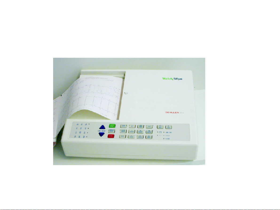
The AT-2 is a 6-channel ECG recorder. All ECG signals are simultaneously processed to provide instant
ECG recordings. Two automatic recording modes can be individually preset to enable one button ECG
recording of preferred print formats.
Individual lamps are provided to give power, paper error, filter, lead group and lead off indications.
In addition, any detected disturbance (i.e. loose electrode or end of paper), gives an audible alarm and
the corresponding indicator lamp flashes.
The AT-2 includes the following features:
n Low weight and compact dimensions
n Large A4 size printout from integrated quality thermal printer
n Built-in rechargeable battery for mains-independent use
n Simple one key operation
n Automatic or manual recording modes
n Selectable printing formats
n ECG memory for easy copying
n Interpretation program option (including measurements)
AT-2
User Guide
Page 5
Page 16
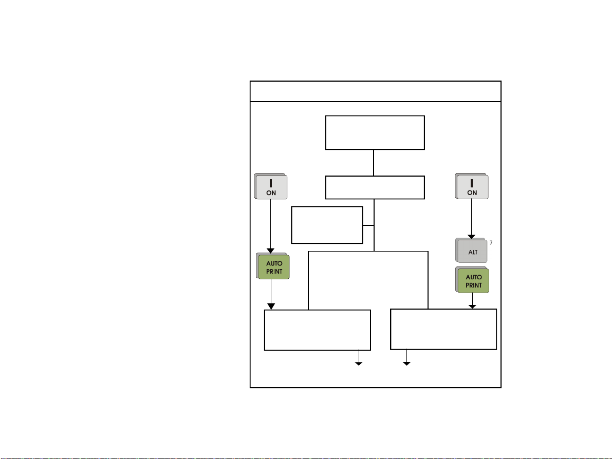
Operation Modes
Automatic Mode
Auto Mode Recording
Automatic Mode provides a printout giving
10 seconds of ECG recording of all 12
leads in 2 different formats.
The following can be programmed freely in
each of the formats before recording:
n Lead Format
n Chart Speed
n With the optional interpretation
progam installed is also possible to
select the measurement table, average cycles with optional markings
and interpretation statements for the
printout.
For further information, see paragraph "Settings for Automatic Mode".
Page 6
Connect Patient
Pages 28 to 30
Switch Unit ON
Settings
Pages 11 to 27
Automatic Recording
in Format 1
Pages 31 to 32
12 lead printout
Automatic Recording
in Format 2
Pages 31 to 32
AT-2
User Guide
Page 17
Operation Modes
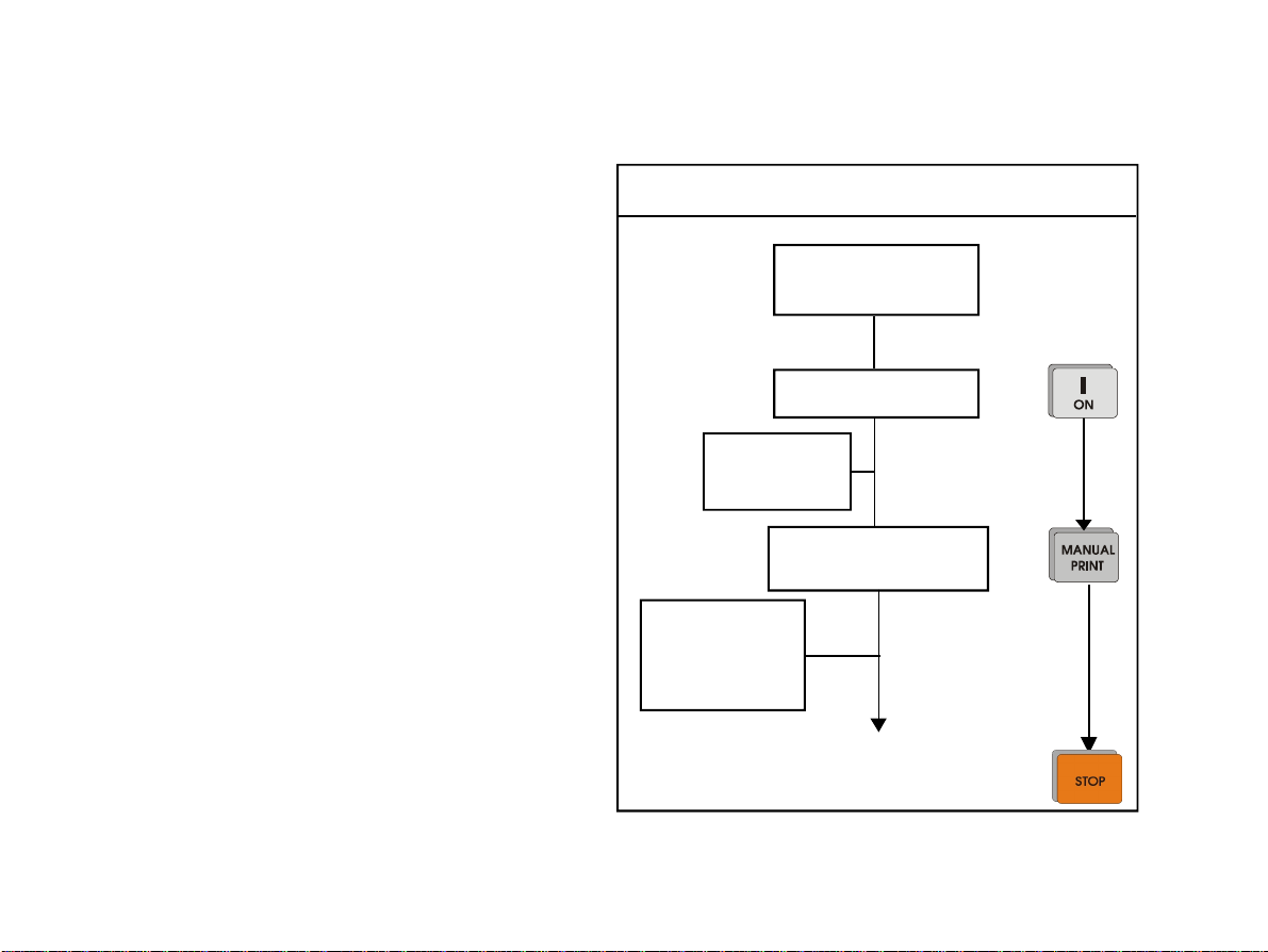
Manual Mode
Manual Mode Recording
Manual Mode provides a real time printout
of 6 leads that are selected and indicated
on the keyboard.
The following can be freely selected before
or during recording:
n Lead Group
n Chart Speed
n Sensitivity
n Myogram Filter
For further information see paragraph "ECG
Recording in Manual Mode".
AT-2
User Guide
Connect Patient
Pages 28 to 30
Switch Unit ON
Settings
Pages 11 to 27
Manual Recording
Pages 33 to 34
Leads, Speed,
Sensitivity,
Myogram filter
Pages 18 + 33
Continuous printout of 6 leads
Page 7
Page 18

Location & Power
Location
Do no keep or operate the apparatus in a we, moist or duty environment. Also, avoid
exposure to direct sunlight or heat from other sources. Do not allow the unit to come
into contact with acidic vapours or liquids, as such contact may cause irreparable
damage. The unit should not be placed near X-ray or diathermy units, large transformers or motors.
The unit must be placed on a flat surface. The unit should not be operated in areas
where there is any danger of explosion.
Power Supply
The unit can either be operated from the built-in rechargeable battery or from the
mains.
The mains connection is on the rear of the unit. The mains indicator lamp is always
lit when the unit is connected to the mains supply.
A battery indicator lamp confirms battery operation. When the battery capacity is
limited, the indicator flashes. To recharge the battery, connect the apparatus to the
mains supply by means of the supplied power cable. A totally discharged battery
needs less than 15 hours to be fully recharged (60% in less than 3 hours, 90% in
less than 7 hours).
A fully charged battery lasts approximately 3-4 hours of normal use. The unit can
remain connected to the mains supply without any danger of damage to either the
battery or the unit.
Page 8
AT-2
User Guide
Page 19
Basic Information
Switching On and Off
The AT-2 is swiched on by means of the green key and off by means of the red key. .
The unit is switched off after 5 minutes (30 seconds if battery capacity is limited) if no key is pressed
and the patient cable is not disconnected.
Potential Equalization
If the AT-2 is used in conjunction with other patient connected equipment, we recommend that the
potential equalization stud ( ) on the rear of the unit is connected to the hospital/building commond
ground with the yellow/green ground cable (Part. no. 2.310 005).
When working from an emergency vehicle, the vehicle common ground can be used.
AT-2
User Guide
Page 9
Page 20
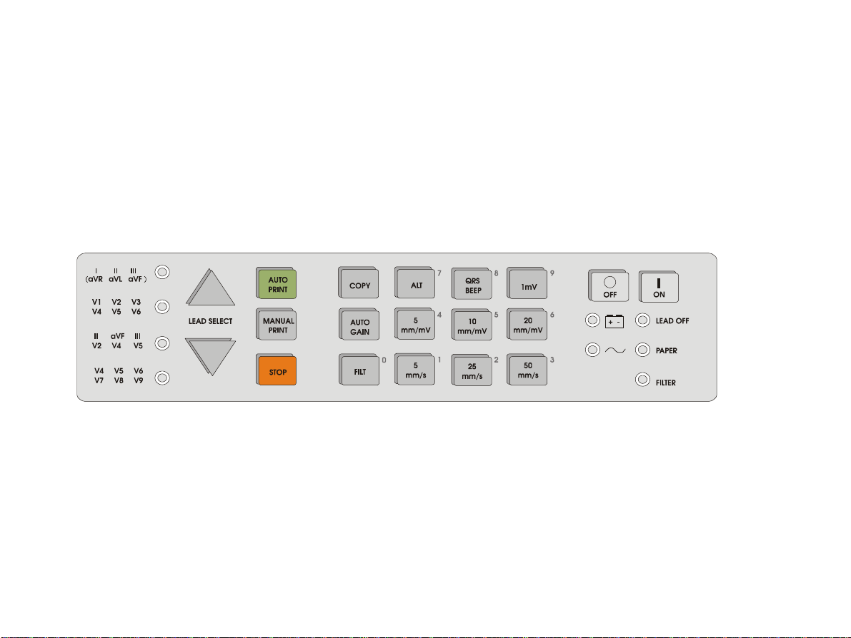
Keyboard
Page 10
AT-2
User Guide
Page 21
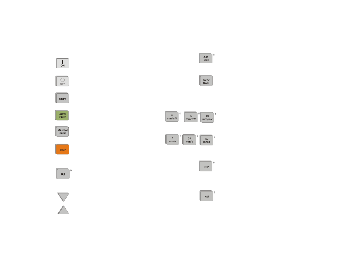
Keyboard
Switch unit on
Switch unit off
Copy stored ECG
Start automatic recording
Start manual recording
Stop recording/move paper to start
position
Swith myogram filter (muscle
tremor filter) on or off
Lead group selector (forward)
Lead group selector (backward)
AT-2
User Guide
Cancel or enable QRS beeper
Automatic ECG sensitivity adjustment
from 10 to 5 mm/mV in order to avoid
overlapping traces in automatic mode
only
ECG sensitivity selector (5, 10 or 20 mm/
mV) manual recording only
Chart speed selector (5, 25 or 50 mm/s)
manual recording only
Key for 1mV indication mark on output
druing manual recording. Use this key
also for baseline recentering.
Key for initiation of setups and selection
of second format for printout.
Page 11
Page 22

Indicators
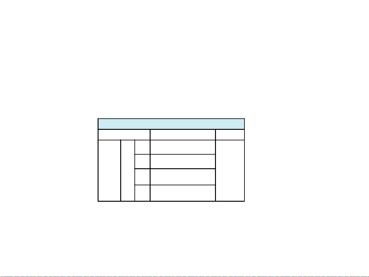
I II III
II aVF III
LEAD OFF
+ -
Mains indicator (lit when mains connected)
Battery lamp (lit when running on battey power - mains not connected) (blinking
when battery capacity is limited)
Warning lamp for loose electrode connection or poor electrode contact
PAPER
FILTER
(aVR aVL aVF )
V1 V2 V3
V4 V5 V6
V2 V4 V5
V4 V5 V6
V7 V8 V9
Page 12
Warning lamp for end of paper or paper jam
Myogram filter (lit when filter ON)
Indicator lamp for selected lead group (Standard)
(Cabrerea: aVL, l, -aVR, II, aVF, III) in manual mode only
Indicator lamp for selected lead group (Standard) in manual mode only
Indicator lamp for selected lead group in manual mode only
Indicator lamp for selected lead group in manual mode only
AT-2
User Guide
Page 23
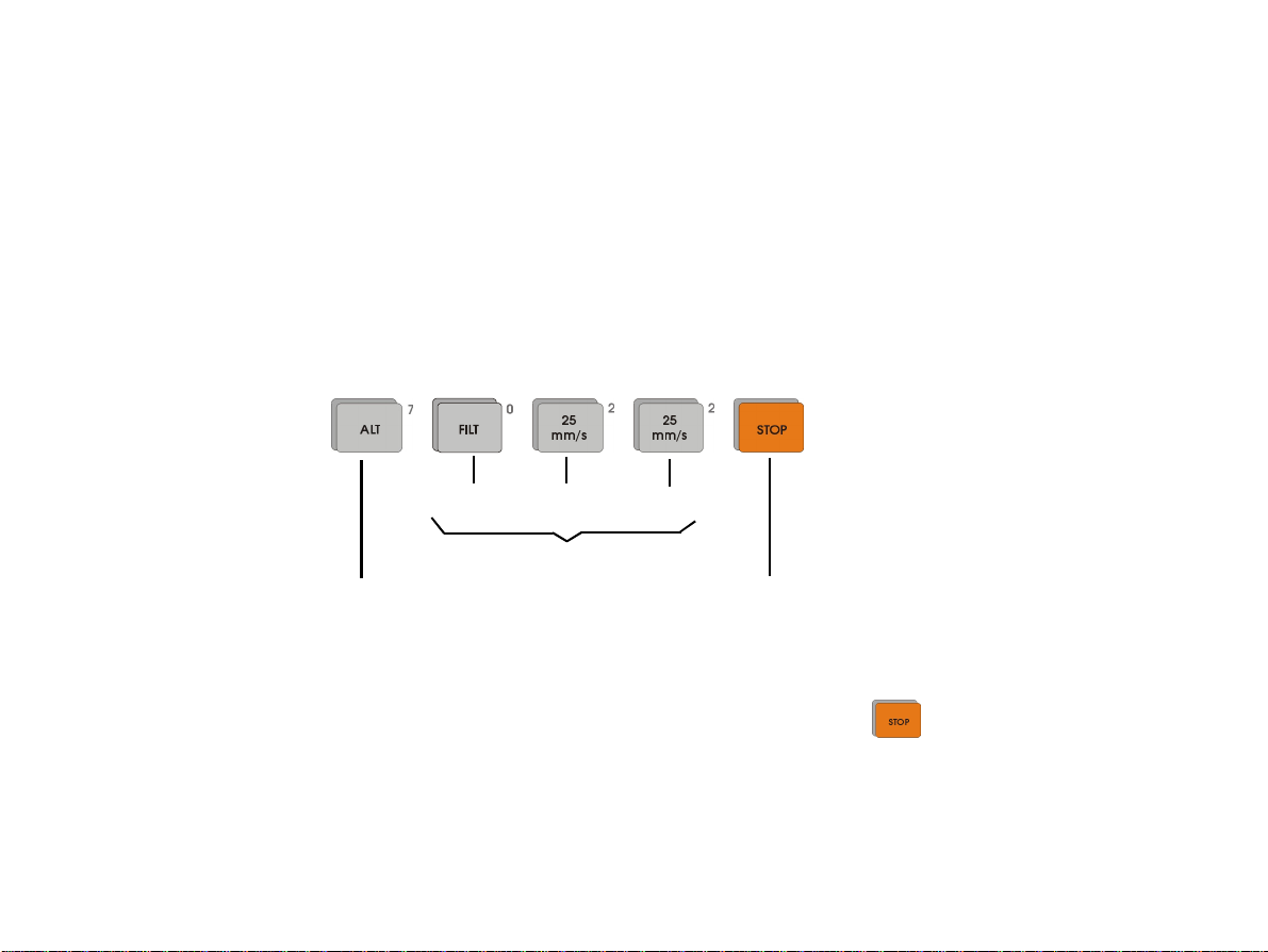
General Settings
Each parameter is set by means of a code. This code comprises a combination starting with the ALT
key followed by a number of keays and is always confirmed with the STOP key. As soon as the ALT key
is pressed, the keyboard is dedicated to the programming function.
The setting is remembered and the keyboard is only released for other functions when the STOP key is
pressed. Once the settings have been confirmed, they are stored in the memory even when the unit is
switched off. As an example, if you wnat to set the language on your AT-2 to English, proceed as follows:
+ + + +
key 0 key 2 key 2
Program sequence
Start programming / CONFIRM SETTING
Switch to numerical keyboard
On the following pages the progammable parameters and the programming sequences are described in
detail.
NOTE THAT THE SETTINGS ARE ALWAYS CONFIRMED BY PRESSING THE KEY. .
AT-2
User Guide
Page 13
Page 24
General Settings
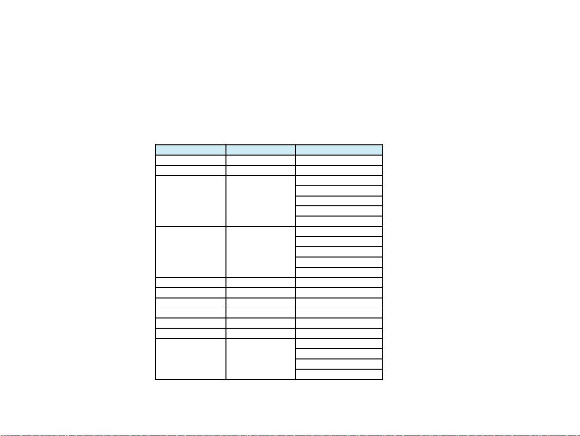
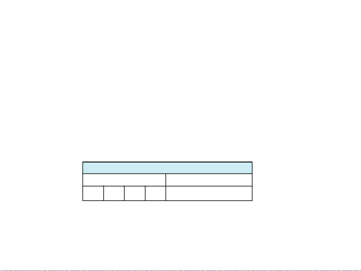
Default Settings
Settings AT-2 AT-2 with interpretation option
Language English English
Leads Standard (S) Standard (S)
Auto Format 1 ECG: 25mm/s, short (o)
Auto Format 2 ECG: 25mm/s, long (ooo)
Rhythm Leads V1, II
Autom. Centering enabled (+) enabled (+)
Printout of signals sequential sequential
Baseline Filter Settings 0.05Hz 0.05Hz
Mains Filter Settings 50Hz (115V - 60Hz) 50Hz (115V - 60Hz)
Myogram Filter Settings 35Hz, OFF 35Hz, OFF
Interpretations Settings
Page 14
ECG: 25mm/s, short (o)
MECG: 6*2 50mm/s+1(V1)
Measurement: suppressed (-)
Interptretation: enabled (+)
Marks: enabled (+)
ECG: 25mm/s, long (ooo)
MECG: none
Measurement: suppressed (-)
Interpretation: suppressed (-)
Marks: enabled (+)
N/A: suppressed
U: enabled (+)
A30: Under thirty (-)
S: Low (-)
AT-2
User Guide
Page 25
General Settings
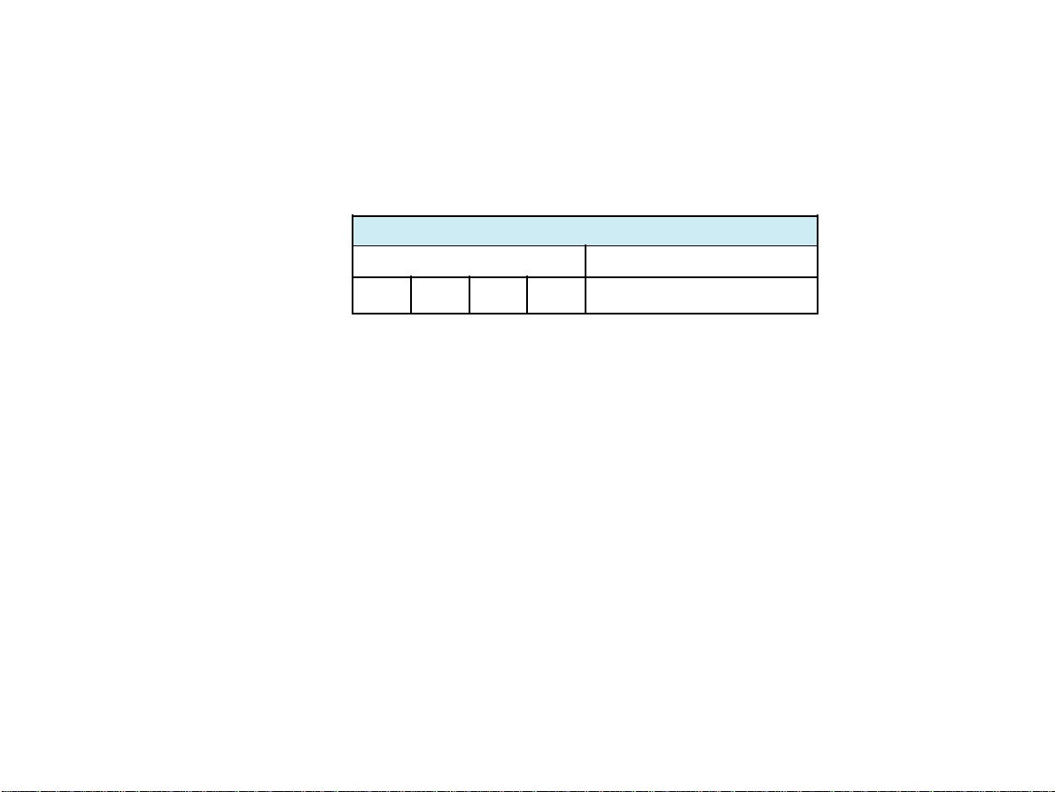
The defined formats and settings can be checked as follows:
Setup Printout
Entry Key Sequence Action
ALT 0 1 1 Printout of programmed settings
A printout of the defined settings will be produced and gives the following information, depending on the
installed software:
Unit designation (AT-2), Software option installed (i = interpretation) and Software version
Serial number
Leads Standard (S) or Cabrera (C)
ECG Format Long (ooo), Short (o) or Suppressed (-)
MECG Average cycles as defined in auto ECG recording setup (e.g. 4*3 (25 mm/s)+2)
Measurements Enabled (+) or Suppressed (-)
Marks Enabled (+) or Suppressed (-)
Interpretation Enabled (+) or Suppressed (-)
Selected Rhythm leads Leads selected for R1, R2 resp.
Automatic Centering Enabled (+) or Suppressed (-)
Printout of Signals Sequential or Simultaneous
AT-2
User Guide
Page 15
Page 26
General Settings
Baseline Filter 0.05, 0.15 or 0.30 Hz
Mains Filter 50, 60 Hz or OFF (-)
Myogram Filter 25 or 35 Hz, ON (1) or OFF (-)
Interpretation settings N/A: +/- ('normal/abnormal' is written (+) or suppressed (-);
U: +/- ('unconfirmed report' is written (+) or suppressed (-);
A30: +/- (patient age is assumed to be < 30 (-) or > 30 (+);
S: +/- (low (-) or high (+) sensitivity)
To reset the unit to the basic default settings, proceed as follows:
Reset Setup
Entry Key Sequence Action
ALT 0 9 6 Reset to default American base settings
Page 16
AT-2
User Guide
Page 27
General Settings
The language is selected as follows:
Entry Key Sequence Language Confirm
Select Language
1 German
2 English
3 French
ALT 0 2
4 Swedish
5 American
6 Italian
7 Spanish
8 Portuguese
Press
STOP key
Confirm the selection by pressing STOP.
Note: Once selected, the language remains active. However, when the unit is reset to the default settings, the default language will be English.
AT-2
User Guide
Page 17
Page 28
General Settings
There are three different filters which can be set individually as follows:
n Baseline filter
n Mains filter
n Myogram filter
The setting for each filter is given on the setup printout.
Baseline Filter
The digital Baseline filter suppresses excessive baseline drifts. The setting options are as follows:
Baseline Filter
Entry Key Sequence Filter Setting Confirm
0 0.05 Hz (Default)
ALT 5
The set value is the lower limit of the frequency range and is normally set to 0.05 Hz. The settings 0.15
and 0.30 Hz should only be used when absolutely necessary, as the possibility exists that they could
affect the original ECG signal, especially the ST segments.
Confirm the selection by pressing STOP.
1 0.15 Hz
3 0.30 Hz
Page 18
Press
STOP key
AT-2
User Guide
Page 29
General Settings
Mains Filter
The Mains filter is an adaptive digital interference filter designed to suppress AC interference without
attenuating or distoring the ECG.
Set the mains filter in accordance with the frequency of your local mains supply as follows:
Mains Filter
Entry Key Sequence Filter Setting Confirm
5 50 Hz
AT-2
User Guide
ALT 8
6 60 Hz
9 Filter off
Press
STOP key
Page 19
Page 30
General Settings
Myogram Filter
The Myogram filter suppresses disturbances caused by strong muscle tremor. The cutoff frequency of
the myogram filter is set to 25 or 35 Hz. The myogram filter is switched on and off manually with the FILT
key. Switching on or off can also be programmed as default when the unit is swiched on. When the filter
is active, the 'FILTER' lamp on the unit is lit.
Myogram Filter
Entry Key Sequence Filter Setting Confirm
2 25 Hz
ALT 8
3 35 Hz
ON when switching on unit
1
(marked on printout with +)
OFF when switching on unit
8
(marked on printout with -)
Press
STOP key
Confirm the selection by pressing STOP.
An ECG recorded in auto mode is stored unfiltered. It is therefore possible to print the stored ECG either
with or without passing the myogram filter.
AT-2
Page 20
User Guide
Page 31

General Settings
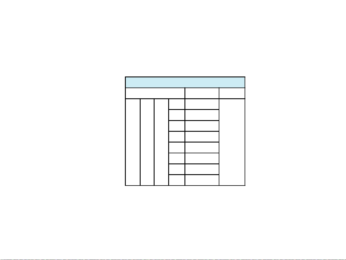
Defining Lead Sequence & Printout
The required settings can be selected as follows:
Sequences & Print
Entry Key
Sequence
1 Standard Lead Sequence
2 Cabrera Lead Sequence
ALT 7
Confirm the selection by pressing STOP.
The selectable lead groups for the AT-2 are:
I
II
III
aVR
aVL
AT-2
aVF
User Guide
3 Simultaneous Print
4 Sequential Print
5 Auto-Centering ON
6 Auto-Centering OFF
Lead Groups
Standard Cabrera
V1
II
V2
aVF
V3
III
V4
V2
V5
V4
V6
V5
Definition Confirm
V4
aVL
-aVR
aVF
III
V1
I
V2
aVF
V3
II
V4
V5
V6
V5
V6
V7
V8
V9
Press
STOP key
II
III
V2
V4
V5
V4
V5
V6
V7
V8
V9
Page 21
Page 32

General Settings
The selectable printout forms are:
Simultaneous All ECG leas are printed in the same time segment (in automatic mode only)
Sequential Each group is a contiguous time segment of approximately 2.5 or 5 seconds
(in automatic mode only).
Auto-Centering ON All ECG traces are centred dynamically for optimal use of paper width.
Auto-Centering OFF ECG traces are set to a fixed baseline position and may possibly overlap.
Acoustic QRS Indication
The acoustic QRS indication can be switched on or off at any time by pressing the key..
Page 22
AT-2
User Guide
Page 33

General Settings
Time / Date
Time:
ALT 9 1 1 HHMMSS beep
Date:
ALT 9 2 2 DDMMYY beep
Wintertime to Summertime (+ 1h)
ALT 9 4 4
Summertime to Wintertime ( - 1h)
ALT 9 5 5
Change Time / Date
AT-2
User Guide
Page 23
Page 34

Settings for Automatic Mode
Two separate formats for the automatic ECG output can be selected as follows:
Automatic ECG Format
Entry Key Sequence Setup Format
ALT
With this the 2 automatic mode formats are defined as detailed on the following pages.
The ECG format is set as follows:
Entry Key Sequence Output Format Confirm
5 No leads are printed
6 Leads are printed in short form (1 sheet)
ALT1or21
7 Leads are printed in long form (2 sheets)
8 Chart speed is 25 mm/s
9 Chart speed is 50 mm/s
0 Leads are printed in format 4 x 3 + 1 Rhy
Confirm the selection by pressing STOP.
1 Setup Format 1
2 Setup Format 2
ECG Format
Press
STOP key
Note: Lead selection for the rhythm lead is defined on page 29.
Page 24
AT-2
User Guide
Page 35

Settings for Automatic Mode
Average Cycles
The Average cycles are defined as follows:
Average Cycles (Interpretation Option only)
Entry Key Sequence Output Format Confirm
5 No average cycles are printed.
4*3 (25 mm/s) + 2*Rhy (25 mm/s)
6
The average complexes are printed out in four groups of three
leads with 2 rhythm leads at a chart speed of 25 mm/s.
ALT 1 or 2 2
Confirm the selection by pressing STOP.
Note: Lead selection for the 2 rhythm leads is defined on page 29.
4*3 (50 mm/s) + 2* Rhy (25 mm/s)
7
The average complexes are printed out in four groups of three
leads with 2 rhythm leads at a chart speed of 50 mm/s.
6*2 (50 mm/s) + 2*Rhy (25 mm/s)
8
The average complexes are printed out in six groups of two
leads with two rhythm leads at a chart speed of 50 mm/s.
Press
STOP key
AT-2
User Guide
Page 25
Page 36

Settings for Automatic Mode
Measurements and Markings
To define the measurements and markings proceed as follows:
Measurements and Markings (Interpretation Option only)
Entry Key Sequence Output Format Confirm
Detailed table of measurement results is ommitted
5
(However, the values of electrical axes, intervals and heart
rate are not suppressed).
ALT1or23
Confirm the selection by pressing STOP.
6 Detailed table of measurement results is printed.
Reference markings (beginning and end of P wave and
7
QRS as well as end of T wave) are omitted.
Reference markings (beginning and end of P wave and
8
QRS as well as end of T wave) are added to ECG cycles.
Press
STOP key
Page 26
AT-2
User Guide
Page 37

Settings for Automatic Mode
Interpretation
To print or suppress interpretation statements on the printout proceed as follows:
Interpretation (Interpretation Option Only)
Entry Key Sequence Output Format Confirm
5 Interpretation is omitted
ALT 1 or 2 4
6 Interpretation is printed
Press
STOP key
Confirm the selection by pressing STOP.
Full details of the interpretation option are given in the SCHILLER ECG Measurement and Interpretation
booklet - see later.
AT-2
User Guide
Page 27
Page 38

Settings for Automatic Mode
Interpretation Settings
The interpretation settings enable the user to determine whether or not certain comments will be added
to the interpretation statements on the ECG printout. Furthermore, the patient's age can be defined (< or
> 30) and if low or high sensitivity should be applied. Low sensitivity will suppress certain nonspecific
ECG diagnosis; this may be advisable when carrying out ECGs for screening.
Interpretation Settings
Entry Key Sequence Setting Confirm
1 "Normal" / "Abnormal" is not printed
2 "Normal" / "Abnormal" is printed
3 "Unconfirmed report" is not printed
ALT 6
4 "Unconfirmed report" is printed
5 Patient age assumed to be <30
6 Patient age assumed to be >30
7 Low sensitivity
8 High sensitivity
Press
STOP key
Page 28
AT-2
User Guide
Page 39

Settings for Automatic Mode
Selecting Rhythm Leads
The rhythm leads are printed out as defined. Two separate rhythm leads can be selected. The following
formats can be set:
Rhythm Leads
Entry Key Sequence Setup Lead
ALT
The 2 rhythm leads are defined as follows:
3 Setup Rhythm Lead 1
4 Setup Rhythm Lead 2
Extremity Leads
Entry Key Sequence Lead Confirm
1 I
2 II
ALT3or48
3 III
4 aVR
5 aVL
6 aVF
Confirm the selection by pressing STOP.
AT-2
User Guide
Press
STOP
Key
Precordial Leads
Entry Key Sequence Lead Confirm
1 V1
2 V2
ALT3or49
3 V3
4 V4
5 V5
6 V6
Press
STOP
Key
Page 29
Page 40

Patient Cable Connections
The accessory kit of the electrocardiograph includes a 10-lead patient cable. This
cable is plugged into the patient cable socket on the right-hand side of the unit and
secured with the two screws.
The AT-2 is CF rated. The patient connection is fully isolated and defibrillation
protected. Protection against defibrillation voltage is however only ensured, if the
original Welch Allyn Schiller patient cable (Part. no. 80180-0000) is used. Make
sure that during ECG recording neither the patient nor the conducting parts for the
patient connection or the electrodes (including the neutral electrode) come into
contact with other persons or conducting objects (even if these are earthed).
Page 30
AT-2
User Guide
Page 41

Patient Cable Connections
The quality of the ECG is dependent on the preparation and the resistance between the skin and the
electrode. To ensure a good quality ECG and minimize the skin/electrode resistance, remember the
following points:
1. Ensure that the patient is warm and relaxed.
2. Shave electrode area before cleaning.
3. Thoroughly clean the area with alcohol.
4. Place the C4 electrode first - in the fifth intercostal space on midclavicular line.
Then place:
n C1 in the fourth intercostal space at the right sternal border
n C2 in the fourth intercostal space at the left sternal border
n C3 between, and equidistant to, C4 and C2
n C6 on left midaxillary line on the smae level as C4
n C5 between, and equidistant to, C4 and C6
Following these simple guidelines will ensure good results every time.
AT-2
User Guide
Page 31
Page 42

Patient Cable Connections
Standard Leads
IEC AHA
N Black RL Green
R Red RA White
C1 White / Red V1 Brown / Red
C2 White / Yellow V2 Brown / Yellow
C3 White / Green V3 Brown / Green
C4 White / Brown V4 Brown / Blue
C5 White / Black V5 Brown / Orange
C6 White / Violet V6 Brown / Violet
L Yellow LA Black
F Green LL Red
Page 32
AT-2
User Guide
Page 43

Recording an ECG in Automatic Mode
In automatic mode, a full 12-lead ECG is printed in one of two predefined formats with a sensitivity of
10 mm/mV. These two formats are selected by the user to suit his specific needs and requirements (as
detailed previously).
When the key is pressed before recording in automatic mode, the unit detects very large
waveforms amplitudes and sets the sensitivity for the extremity and/or precordial leads to 5 mm/mV to
reduce the overlapping of traces.
To start the automatic ECG recording in Format 1, simply press .
To start the automatic recording in the second format, press followed by .
AT-2
User Guide
Page 33
Page 44

Recording an ECG in Automatic Mode
The printout provides you with the following information:
- ECG recording of all leads in either Standard or Cabrera format according to selection
- Sensitivity
- Heart Rate
- Speed
- Filter Settings
- Patient Data field to manually insert patient data
and if set:
- Average Cycles (Interpretation option only)
- Intervals (Interpretation option only)
- Axis (Interpretation option only)
- Sokolow Index (ECG index for hypertrophy; Interpretation option only)
- Detailed Measurement Table (Interpretation option only)
- Interpretation (Interpretation option only)
n To obtain an extra printout of the ECG recording in Format 1, simply press .
n To obtain an extra printout of the second format, press followed by .
Page 34
AT-2
User Guide
Page 45

Recording an ECG in Manual Mode
Manual mode provides a direct printout of the real-time ECG with full control of parameter selection.
The following can be freely chosen during or before the recording:
n Lead Group (by means of the and keys)
The following lead groups are selectable:
- I, II, III, aVR, aVL, aVF (Cabrera: aVL, I, -aVR, II, aVF, III)
- V1, V2, V3, V4, V5, V6
- II, aVF, III, V2, V4, V5
- V4, V5, V6, V7, V8, V9
n Chart Speed (by means of the , and keys)
n Sensitivity (by means of the , and keys)
n Filter see page 18.
AT-2
User Guide
Page 35
Page 46

Recording an ECG in Manual Mode
To start the manual recording of a real-time ECG, press the key. .
The printout provides you with the following informaton:
- The group of the six selected leads with lead identification
- On the lower edge chart speed, sensitivity and filter settings (if on) are given.
- At the top, the heart rate as current average of 4 beats is shown.
To re-centre the ECG traces, press the key during operation.
Finish the recording by pressing the key. .
WARNING
AFTER HEA VY ARTEFACTS OR LEAD OFF, THE INDICA TION OF THE HEART RATE
MAY NOT BE RELIABLE.
Page 36
AT-2
User Guide
Page 47

Care & Maintenance
Care of your AT-2
The patient cable should not be exposed to excessive mechanical stress. Whenever disconnecting the
leads, hold the plugs and not the cables. Aling the leads in such a way as to prevent anyone stumbling
over them or any damage caused by the wheels of instruments trolleys. The cable can be wiped with
soapy water. Sterilization, if required, should be done with gas only and not with steam. To disinfect,
wipe the cable with any standard hospital disinfectant.
The casing of the AT-2 should be cleaned with a soft cloth on the surface only.
DISCONNECT THE UNIT BEFORE CLEANING . DO NOT , UNDER ANY CIRCUMSTANCES,
IMMERSE THE APPARATUS INTO A CLEANING LIQUID OR STERILIZE WITH HOT WATER, STEAM OR AIR.
Self-test
Initiate a self-test of the AT-2 as follows:
A table giving information for the service staff is printed out.
Initiate Self-Test
Entry Key Sequence Action
ALT 0 3 3 Printout of Self-test
AT-2
User Guide
Page 37
Page 48

Care & Maintenance
12 Monthly Check
The unit should undergo a technical safety check every 12 months. This saefty check should extend to
include the following:
n Visual inspection of the unit and cables.
n Electrical safety tests according to the IEC 601-1 and IEC 601-2-25.
n Functional tests according to the Service Handbook.
The test results must be documented.
Cleaning the Print Head
If the printer is used a lot, a residue of printers ink (from the grid on the printer paper) can build up on the
print head. This can cause the print quality to deteriorate. We recommend therefore that every month
the print head is cleaned with alcohol as follows:
n Remove the paper tray. The print head is found under, and in from, the paper tray release
catch.
n With a tissue dampened with alcohol, gently rub the print head to remove the ink residue.
If the print head is badly soiled, the colour of the grid ink will show on the tissue.
Page 38
AT-2
User Guide
Page 49

Replacing the Recording Paper
The recording paper must be replaced as soon as the end of the paper is indicated by a red stripe on the
lower edge. After the indication first appears, there are about 8 pages left. However, we recommend that
the paper be replaced immediately.
If no paper is left, the printing process is interrupted and the paper waning lamp starts to blink. After the
paper has been replaced, the printout is restarted by pressing COPY or MANUAL PRINT or AUTO
PRINT.
A step-by-step description of how to change the paper is given on the next page.
AT-2
User Guide
Page 39
Page 50

Replacing the Recording Paper
n Place fingers under the retaining bar and pull
directly upwards. The paper tray cover releases.
n Withdraw the cover from the unit. DO NOT
FORCE, THE PAPER TRAY COVER RUNS
FREELY OVER THE DEDICATED RUNNERS.
Paper
grid side up
Paper tray
release bar
n Remove any remaining paper from the paper
tray.
Paper tray cover
Paper roller
n Place an new paper pack into the paper tray
with the printed (grid) side facing upwards.
n Place the beginning of the paper over the
black paper roller on the paper tray cover.
n Return the paper tray cover in position and
press firmly until secure.
n Press the STOP key to transport the paper
to the start position.
Welch Allyn Schiller can only guarantee perfect printouts when Welch Allyn Schiller original chart paper
or chart paper of the same quality is used.
Page 40
AT-2
User Guide
Page 51

Trouble Shooting
Problem What to Check
Unit does not switch on /
Mains indicator lamp is not lit
"Noisy" traces
ECG trace 'wanders' away
from centre
Poor quality printout / ECG
traces 'breaking up'
No printout
AT-2
User Guide
Check if mains cable is plugged in. Call your local Welch Allyn Schiller
dealer if problem is still present.
CHECK ELECTRODE CONTACT. As much as possible, ensure that patient
is relaxed and warm. Activate myogram filter to reduce muscle tremor.
Check mains filter to 50 or 60 Hz according to local power supply.
Baseline drift - check electrode contact. Press 1mV key to reset baseline.
Select a higher baseline frequency
Thermal print head dirty - clean print head with alcohol. Possible faulty print
head, contact your local service centre. Ensure that the paper tray cover is
clicked into place.
Connect unit to the mains supply. Ensure that the paper tray cover is clicked
into place. Check paper level.
Page 41
Page 52

Technical Data
Technical data subject to change without notice.
Dimensions 400 x 330 x 100mm
Weight 4.25 kg (5.05 kg with full paper tray)
Mains Supply 100 to 115 / 220 to 240 VAC, 50/60 Hz
Battery Built-in 12 V lead-acid battery (rechargeable)
Power Consumption Recording: 28 VA max
Leads Standard / Cabrera
Paper Speed 5 / 25 / 50 mm/s (direct)
Sensitivity 5 / 10 / 20 mm/V, either automatically adjusted or manually selected
Chart Paper Thermoreactive z-folded, 210 mm wide, perforation 280 mm
Printing Process High-resolution thermal print head, 8 dots per mm
Recording Tracks 6 channels, positioned at optimal width on 200 mm, automatic
baseline adjustment
Automatic Lead Programs 6 channel representation of 12 simultaneously acquired standard
leads
Page 42
AT-2
User Guide
Page 53

Technical Data
Data Record Listing of ECG recording data
Version C: ECG measurement results (intervals, amplitudes, electri-
cal axes), Sokolow Index, average complexes with optional measure-
ment reference markings and interpretation.
ECG Storage Memory for 10 s, 12-lead ECG
Circular input memory for 10 s, 12-lead ECG.
Frequency Range of Digital Recorder
0 to 150 Hz (IEC)
0 to 150 Hz (AHA)
AT-2
User Guide
Page 43
Page 54

Technical Data
ECG Amplifier: Simultaneous, synchronous registration of all 9 active electrode
signals (= 12 standard leads)
Sampling frequency: 1000 Hz
Digital resolution: 5m V
Dynamic range: ± 10 mVAC
Max. electrode potential: ± 300 mVDC
Time constant: 3.2 s
Frequency response: 0.05 to 150 Hz (-3 dB)
Input impedance: > 10 MW
Myogram Filter (muscle tremor filter):
25 Hz or 35 Hz, programmable (not active on averaged waveforms).
The stored ECGs can be printed with or without filter.
Line Frequency Filter: Distortion-free suppression of superimposed 50 or 60 Hz sinusoidal
interferences by means of an adaptive digital filter.
Patient Input: Fully floating and isolated, defibrillation protected.
Patient Leakage Current: > 5m A
Page 44
AT-2
User Guide
Page 55

Technical Data
Safety Standard: CF according to IEC and complying with the following:
RL 93/42/EEC
EN 60601-1: 1990
IEC 601-1
IEC 601-2-25: 1993
pr EN 1441: 1994
EMC: CISPR 111: 1985, EN 55011: 1992
IEC 801-2: 1991
IEC 801-3: 1984
IEC 801-4: 1988
IEC 801-5:
Safety Class: I according to IEC 601-1 (with internal power supply)
IIa according to RL 93/92/EEC, CE-0123
AT-2
User Guide
Page 45
Page 56

Technical Data
Environment Conditions: Temperature, Operating: 10° to 40°C
Temperature, Storage: -10° to 50°C
Relative humidity: 25 to 95% (non condensing)
Atmospheric pressure: 700 to 1060 hPa
Control Panel: Rubber keys
Available Configurations
The AT-2 is available in the two versions:
Standard Version: Unit with ECG recording and printout capabilities.
Version C: Unit with additional ECG interpretation program (including measure-
ment).
Page 46
AT-2
User Guide
Page 57

Garantie
L'electrocardiograph AT-2 est garanti sans défaut matériel ou de fabrication et à
fonction d'après la déclaration du fabricant pendant trois (3) ans à partir de la date
de vente. Pour les accessoires comme des électrodes, batteries et le câble, il y a
une garantie limitée à 90 jours dès la date de vente chez Welch Allyn Schiller, un
centre de vente autorisé ou un représentant autorisé. Welch Allyn Schiller accomplie
des réparations ou remplace des pièces défectueuses ou des pièces qui s'écartent
de la spécification faite par le fabricant, sans frais et durant la garantie mentionnée.
Il est de la résponsabilité du vendeur de renvoyer l'appareil à Welch Allyn Schiller, au
centre de vente autorisé, au représentant autorisé ou au centre de service. Exclus
de cette garantie sont les défauts dus à une manipulation frauduleuse, un mauvais
emploi, une négligence, un accident, une manipulation impropre ou des défauts dus
au transport. Des réparations par du personnel non autorisé ou non qualifiée et
l'usage non conformément à la déclaration du fabricant annulent la garantie.
i
Page 58

RESPONSIBILITÉ DU MÉDECIN
Le AT-2 electrocardiographe est destiné uniquement à l'usage de médecins qualifié
ou de personnel sous leur supervision directe. Les résultats numériques et graphiques
d'un enregistrement sont à mettre en relation avec l'état de santé général du patient.
Egalement à prendre en considération sont la qualité de la préparation de
l'enregistrement ainsi que la qualité générale des données enregistrées. Celles-ci
sont susceptibles d'influencer les résultats et données fournies.
Il incombe au médecin d'établir un diagnostic ou d'obtenir un avis d'expert sur les
résultats, puis de mettre en oeuvre le traitement médical approprié.
Aux États-Unis, la loi fédérale limite la commercialisation de cet appareil à la vente
pour un médecin ou sur commande d'un médecin.
ii
Page 59

Notice de Sécurité
Pour eviter tout risque de choc électrique, ne jamais démonter l'appareil. Aucun élément interne ne doit
être remplacé régulièrement . Seul un personnel qualifié peut intervenir sur l'appareil .
Ne pas utiliser l'appareil dans des zones à risque d'explosion ou en présence de gaz inflammables tels
les gaz anesthésiques.
Cet appareil n'est pas déstiné à un usage sterile.
Cet appareil n'est pas destiné pour être utilisé à l'exterieur.
Avant de procéder au nettoyage , arrêter l'appareil et débrancher le cable du secteur.
Ne jamais, en aucun cas, immerger l'appareil ou les câbles dans un liquide.
L’appareil ne doit fonctionner que sur la batterie si le branchement à la terre est suspect ou si le câble
du secteur est endommagé ou suceptible d’avoir été endommagé.
Ne pas procéder à une stérilisation haute temperature (autoclave). Ne pas utiliser de rayons électriques
ou gamma.
Ne pas utiliser de solvant pour nettoyer l'appareil.
N'utiliser que les accessoires et autres pièces recommandés ou fournis par Welch Allyn Schiller.
L'utilisation de pièces ou accessoires non recommandés peut générer des dégâts matériels et/ou corporels
iii
Page 60

Cet appareil respècte les régulations CEM pour appareils médicaux et il est protégé contre les interférences
et les emissions électriques . Cependant, accorder un soin particulier quand l'appareil est utilisé avec
un appareillage de haute fréquence.
Il faut s'assurer que ni le patient ni les électrodes (y compris l'électrode neutre) ne viennent en contact
avec d'autres personnes ou des objets conducteurs (même branchés à la terre).
Il n'y a pas de danger à faire un ECG pour un patient avec stimulateur cardiaque ou simultanément
avec d'autres équipements électriques de stimulation. Néanmoins, les unités de stimulation doivent
rester à une distance suffisante des électrodes. En cas de doute, déconnecter le patient du moniteur.
Cet appareil est classé CF selon IEC 601-1. Cela signifie que les branchements du patient sont
complètement isolés et protégés contre la défibrillation. Cependant Welch Allyn Schiller ne peut
garantir cette protection contre le courant de défibrillation que si le câble patient Welch Allyn
Schiller original est utilisé.
Si plusieurs unités sont couplées, les courants de fuite peuvent s'ajouter et représenter un danger.
Ne pas toucher le boîtier de l'appareil durant une défibrillation.
Si les câbles patient ont été endommagés par une défibrillation, la mention électrodes débranchées
s'affiche et une alarme sonore se déclenche.
iv
Page 61

Cet appareil a été testé et s'est avèré conforme aux limites prévues pour les appareils numéreques de
classe A et à partie 15 des réglements FCC et à la réglementation des radio-interférences du Canadian
Department of communications. Ces limites sont destinées à fournier une protection adéquate contre
les interférences néfastes lorsque l'appareil est utilisé dans un environnement commercial. Cet appareil
génère, utilise et peut radier une énergie à fréquence radioélectrique; il est en autre susceptible
d'engendrer des interférences avec les communications radio, s'il n'est pas installé et utilisé
conformément aux instructions du mode d'emploi. L'utilisation de cet appareil dans les zones
résidentielles peut causer des interférences néfastes, auquel cas l'explaitant sera amené à pendre les
dispositions utiles pour parlier aux interférences à ses propres frais.
Elimination et
Manipulation de la Pile
° NE JAMAIS JETER LA PILE OU BATTERIE DANS LE FEU OU DANS
UN INCINERA TEUR - DANGER D'EXPLOSION
° NE JAMAIS RECHARGER LA PILE OU BATTERIE - DANGER
D'EXPLOSION
° NE JAMAIS OUVRIR LE BOITIER DE LA PILE - DANGER DE
BRULURE A L'ACIDE.
N'éliminer la pile ou batterie que dans les centres de recyclages officiels
ou dans les zones autorisées par la municipalité. Il est aussi possible
de renvoyer à Welch Allyn Schiller les piles ou batteries usagées.
Elimination des Appareils
Les appareils qui ne sont plus en usage peuvent être renvoyés à Welch
Allyn Schiller qui se chargera de leur recyclage. vous pouvez aussi les
déposer aux centres de recyclage de la municipalité.
v
Page 62

Alimentation Electrique
Le branchement secteur se trouve à l'arrière de l'appareil.
Le voltage est fixé par l'entreprise à 100-115V (nom. 110V) ou 220-240V (nom. 230V).
Le réglage est indiqué à l'aide de la petite bande de métal qui se trouve sur la plaque de fusibles.
Appeler votre agent Schiller, si vous devez changer le voltage.
Le voyant lumineux du secteur, sur le clavier, s'allume dès que l'appareil est branché. L'appareil peut
être alimenté soit par le secteur soit par la batterie interne rechargeable.
Changement de fusible secteur
S'il est nécessaire de changer un fusible, remplacez le toujours avec la référence correcte, c'est à dire
2x200mAT pour 230V ou 2x315 mAT pour 110V.
Pour changer un fusible, appuyer sur les deux languettes de chaque côté du fusible (sous le connecteur
secteur à l'arrière). Enlever la plaquette du fusible et remplacer le(s) fusible(s). Replacer la plaquette du
fusible.
vi
Page 63

AT-2 Mode d'emploi
Le present mode d'emploi contient toutes les indications nécessaires pour guider
l'utilisateur d'une manière aisée et claire à travers toutes les possibilités d'utilisation.
Les procédures à suivre sont décrites, étape par étape, dans une langue simple et
claire, pour familiariser l'utilisateur d'une manière rapide et sûre avec l'appareil. De
très amples indications médicales n'apparaissent que dans le cas où une telle
indication est absolument nécessaire pour mieux comprendre les résultats ou le
déroulement d'un test.
vii
Page 64

viii
Page 65

AT-2
Mode d'emploi
Version Française
Page 1
Page 66

Table of Contents
Introduction........................................................................................................... 5
Modes de fonctionnement ................................................................................... 6
Information de base.............................................................................................. 8
Mise sous/hors tension ................................................................................... 9
Liaison équipotentielle .................................................................................... 9
Clavier ................................................................................................................. 10
Voyants lumineux............................................................................................... 12
Réglages généraux............................................................................................. 13
Réglages standard ....................................................................................... 14
Filtre de base ............................................................................................... 18
Filtre de secteur............................................................................................ 19
Filtre de myogramme.................................................................................... 20
Sélection de la séquence de dérivations et du mode d'impression................ 21
Signal acoustique QRS................................................................................. 22
Heure / Date ................................................................................................. 23
Page 2
AT-2
Mode d'emploi
Page 67

Réglage pour l'enregistrement automatique ..................................................... 24
Cycles moyens ............................................................................................. 25
Mesures de l'ECG et marques de référence.................................................. 26
Interprétation................................................................................................. 27
Sélection des dérivations du rythme.............................................................. 29
Raccordement du patient ................................................................................... 30
Enregistrement automatique de l'ECG .............................................................. 33
Enregistrement manuel de l'ECG....................................................................... 35
Entretien & Maintenance.................................................................................... 37
Autotest ........................................................................................................ 37
Contrôle de sécurité technique (tous les 12 mois) ......................................... 38
Nettoyer la tête de l'imprimante ..................................................................... 38
Remplacer le papier d'enregistrement ............................................................... 39
Dépannage .......................................................................................................... 41
Données techniques .......................................................................................... 42
Modèles disponibles..................................................................................... 46
AT-2
Mode d'emploi
Page 3
Page 68

Page 4
AT-2
Mode d'emploi
Page 69

Introduction
Le AT-2 est un électrocardiographe à six canaux. Tous les signaux d'ECG sont traités simultanément
pour assurer des enregistrements instantanés de l'ECG. Deux formats automatiques peuvent être
préprogrammés séparément. Pour imprimer l'ECG dans l'un ou l'autre format il suffit d'appuyer sur une
touche.
Des voyants lumineux individuels sont prévus pour fournir des indications sur la mise sous tension, le
filtre, les groupes de dérivations, les erreurs au niveau du papier et le mauvais contact des électrodes.
En outre, la détection d'un dérangement quelconque (par exemple électrode détachée ou imprimante à
court de papier) déclenchera une alarme sonore, et le voyant lumineux correspondant clignotera.
L'appareil AT-2 possède les caractéristiques suivante:
n Faible poids et forme compact
n Impression grand format A4 par une imprimante thermique intégrée de haute qualité
n Batterie intégrée, rechargeable pour l'autonomie de fonctionnement sur secteur
n Utilisation convivale
n Enregistrement manuel ou automatique de l'ECG
n Formats d'impression sélectionnable
n Mémoire d'ECG pour recopier l'ECG
n Option programme d'interprétation (y compris la mesure de l'ECG)
AT-2
Mode d'emploi
Page 5
Page 70

Modes de
fonctionnement
Enregistrement automatique
Mode automatique
En mode automatique, un ECG complet de 12
dérivations sur 10 secondes peut être imprimé
dans deux différents formats.
Les paramètres suivants peuvent être sélectionnés
à volonté avant l'enregistrement:
n format pour les dérivation de l'ECG
n vitesse d'impression
n le tableau des valeurs de mesure, les cy-
cles moyens avec des marques de
référence en option et les indications
diagnositques peuvent également être
sélectionnés pour la configuration
d'impression à condition que l'option
"Interprétation" soit installée.
Pour de plus amples informations, veuillez vous
reporter au paragraphe intitulé "Réglages pour
l'enregistrement automatique".
Page 6
Connecter le patient
Pages 28 à 30
Mise en marche de
l'appareil
Réglages
Pages 11 à 27
Enreg. automatique
dans le format 1
Pages 31 à 32
Enreg. automatique
dans le format 2
impression de 12 dérivations
AT-2
Mode d'emploi
Pages 31 à 32
Page 71

Modes de
fonctionnement
Enregistrement manuel
Mode manuel
En mode manuel, six traces de l'ECG
peuvent être enregistrés en temps réel.
Avant ou pendant l'enregistrement, on peut
sélectionner les paramètres suivants:
n groupe de dérivations
n vitesse d'impression
n sensibilité d'impression
n filtre de myogramme
Pour de plus amples informations, veuillez
vous reporter au paragraphe intitulé
"Enregistrement manuel de l'ECG".
AT-2
Mode d'emploi
Connecter le patient
Pages 28 à 30
Mis en marche de
l'appareil
Réglages
Pages 11 à 27
Enreg. manuel
Pages 33 à 34
Dérivations,
vitesse, sensibilité,
filtre myogramme
Pages 18 + 33
Impression de 6 dérivations
Page 7
Page 72

Information de base
Lieu d'installation
L'appareil doit être entreposé ou utilisé à l'abri de toute humidité ou poussière. Par ailleurs, il faut éviter
toute exposition directe de l'appareil aux rayons solaires ou à d'autres sources de chaleur. L'appareil ne
doit pas entrer en contact avec des vapeurs ou liquides contenant des acides. Ne pas installer l'appareil
à proximité d'installations de radiographie ou de diathermie, de puissants transformateurs ou moteurs.
Il faut poser l'appareil sur une surface plane. L'appareil ne peut être utilisé dans des atmosphères
explosive.
Alimentation
L'appareil peut fonctionner directement sur la batterie incorporée, rechargeable ou sur alimentation secteur.
Le connecteur pour le raccordement au réseau électrique est situé sur la face arrière de l'appareil.
Le voyant lumineux pour le fonctionnement sur secteur s'allume lorsque l'appareil est raccordé au réseau
électrique.
Le voyant lumineux pour fonctionnement sur batterie s'allume lorsque l'appareil fonctionne sur batterie.
Ce voyant lumineux clignote lorsque la charge de la batterie est trop faible. Pour recharger la batterie,
raccordez l'appareil au réseau électrique. La durée de chargement pour une batterie complètement est
de 15 heures (moins de 3 heures pour une charge de 60%, moins de 7 heures pour une charge de 90%).
La durée de fonctionnement avec une batterie complètement rechargée est de 3-4 heures. L'appareil
peut rester raccordé au réseau électrique pendant une longue durée sans risque de détérioration pour
l'appareil et la batterie.
Page 8
AT-2
Mode d'emploi
Page 73

Information de base
Mise sous/hors tension
Pour mettre l'appareil sou tension, appuyer sur la touche , pour le mettre hors tension, appuyez
sur la touche .
L'appareil se coup automatiquement après 5 minutes (30 secondes quand la batterie est limitée) si
aucun signal de l'ECG n'est reçu ou si aucune introduction par clavier ne se fait.
Liaison équipotentielle
Si d'autres appareils sont raccordés au patient lors de l'enregistrement de l'ECG, nosu vous préconisons
de réaliser la liaison équipotentielle avec le câble de liaison équipotentielle (article 2.310 005).
Le câble jauen-vert relie la liaison équipotentielle sur le lieu d'installation avec le connecteur prévu à cet
effet sur la face arrière de l'appareil (identifié par le symbol ).
Lors d'une utilisation dans une ambulance, la liaison équipotentielle devra être réalisée par l'intermédiare
de la terre du véhicle.
AT-2
Mode d'emploi
Page 9
Page 74

Clavier
Page 10
AT-2
Mode d'emploi
Page 75

Clavier
Mettre l'appareil sous tension
Mettre l'appareil hors tension
Recopier l'ECG mémorisé
Démarrer l'enregistrement autom.
de l'ECG
Démarrer l'enregistrement manuel
de l'ECG
Activer/désactiver le signal acoustique
QRS
Adaptation automatique du niveau du
signal de 10 ä 5 mm/mV pour éviter
superposition des traces - uniquement
en mode automatique
Sélection de la sensibilité (5, 10 or 20
mm/mV) uniquement pour le mode
manuel
Arrêter l'impression/avancer le
papier sur le début d'une nouvelle
page
Activer/désactiver le filtre de
myogramme
Sélectionner les groups de
dérivations (en avant)
Sélectionner les groups de
dérivations (en arrière)
AT-2
Mode d'emploi
Sélection de la vitesse (5, 25 or 50 mm/
s) uniquement pour le mode manuel
Introduire un signal d'étalonnage 1mV
manuellement et pour recentrage de la
ligne de base.
Touche de programmation / sélectionner
le 2e format d'impression.for printout.
Page 11
Page 76

Voyants lumineux
I II III
II aVF III
LEAD OFF
+ -
fonctionnement sur secteur (s'allume lorsque l'appareil est raccordé au réseau
électrique)
fonctionnement sur batterie (clignote lorsque la charge de la batterie est trop faible)
Voyant lumineux pour 'électrode détachée' ou mauvais contact des électrodes'
PAPER
FILTER
(aVR aVL aVF )
V1 V2 V3
V4 V5 V6
V2 V4 V5
V4 V5 V6
V7 V8 V9
Page 12
Voyant lumineux pour 'fin de papier' ou 'blocage du papier'
Filtre de myogramme (s'allume lorsque le filtre est activé)
Voyant lumineux pour le group de dérivations sélectionné (Standard)
(Cabrerea: aVL, l, -aVR, II, aVF, III) en mode manuel seulement
Voyant lumineux pour le groupe de dérivations sélectionné (Standard) en mode
manuel seulement
Voyant lumineux pour le group de dérivations sélectionné en mode manuel
seulement
Voyant lumineux pour le group de dérivations sélectionné en mode manuel
seulement
AT-2
Mode d'emploi
Page 77

Réglages généraux
Chacun des paramètres réglables peut être prédéfini et programmé par l'utilisateur à l'aide d'un code
numérique. Pour programmer un code, il faut entrer une série de chiffres en combinaison avec la touche
ALT. L'action sur la touche ALT prépare l'appareil à la programmation. Chaque fois qu'ue touche numérique
est appuyée, elle est acceptée comme une partie de l'entrée du code.
Pour terminer et valider votre entrée, appuyer sur la touche STOP. Le clavier n'est libéré pour d'autres
fonctions que si cette touche est actionnée. Les réglages sont sauvegardés de manière permanente
même lorsque l'appareil est coupé. Supposons que vous voulez sélectionner la langue anglaise pour
l'impression. Pour programmer ce paramètre, entrez le code numérique en appuyant sur les touches
suivantes:
+ + + +
touche 0 touche 2 touche 2
Sequence de programmation
Commencer la programmation/ VALIDER L'ENTREÉ
Les touches du clavier ont la fonction
de touches numériques
Les paramètres programmables et leurs codes numériques sont décrits en détail sur les pages suivantes.
NOTEZ QUE LES ENTRÉES SONT VALIDÉES A L'AIDE DE LA TOUCHE .
AT-2
Mode d'emploi
Page 13
Page 78

Réglages généraux
Réglages standard
Paramètres AT-2 Avec interprétation
Langue Français Français
Dérivations Standard (S) Standard (S)
Format automatique 1 ECG: 25mm/s, court (o)
Format automatique 2 ECG: 25mm/s, long (ooo)
Dérivation rhytmiques V1, II
Centrage automatique En servie (+) En service (+)
Impression des signaux Séquentielle Séquentielle
Paramètres du filtre de
base
Paramètres du filtre de
secteur
Paramètres du filtre de
myogramme
Paramètres
d'interprétations
ECG: 25mm/s, court (o)
MECG: 6*2 50mm/s+1(V1)
Mesures: Désactivées (-)
Interptrétation: en service (+)
Marques: en service (+)
ECG: 25mm/s, long (ooo)
MECG: Non
Mesures: Désactivées (-)
Interprétation: hors service (-)
Marques: en service (+)
0.05Hz 0.05Hz
50Hz (115V - 60Hz) 50Hz (115V - 60Hz)
35Hz, HORS SERVICE 35Hz, HORS SERVICE
N/A: Désactivés (-)
En service (+)
A30: Moins de trent ans (-)
S: Basse (-)
Page 14
AT-2
Mode d'emploi
Page 79

Réglages généraux
Pour vérifier et imprimer les réglages réalisés, entrez la séquence de touches suivante:
Imprimer les sélections
Séquence de touches Résultat
ALT 0 1 1 Imprime les sélections
Une impression des sélections définies est obtenue (les informations imprimée varient en fonction du
logiciel installé:
Type de l'unité (AT-2), Option installée (i = interpretation) et version du logiciel
Numéro de série
Dérivations Standard (S) ou Cabrera (C)
Format ECG Long (ooo), Court (o) ou aucun format (-)
ECG moyen Cycles moyens comme (par exemple 4*3 (25 mm/s)+2)
Mesures activer (+) ou déactiver (-)
Marque de référence activer (+) ou désactiver (-)
Intérpretation activer (+) ou désactiver (-)
Dérivation du rythme dérivation du rythme sélectionnées R1, R2
Centrage automatique activer (+) ou désactiver (-)
Impression des signaux en mode simultané ou séquentiel
AT-2
Mode d'emploi
Page 15
Page 80

Réglages généraux
Filtre de base 0.05, 0.15 or 0.30 Hz
Filtre de secteur 50, 60 Hz ou désactivé (-)
Filtre de myogramme 25 or 35 Hz, activé (1) ou désactivé (-)
Paramètres d'interpretation N/A: +/- ('ECG normal/ECG abnormal' est imprimée (+) ou
supprimée (-);
U: +/- ('Rapport non confirmé' est imprimée (+) ou supprimée
(-);
A30: +/- (le patient a < 30 ans (-) ou > 30 ans (+);
S: +/- (sensitivité basse (-) ou haute (+))
Pour rappeler les réglages standard, il suffit d'appuyer sur les touches suivantes:
Rappeler les réglages standard
Séquence de touches Résultat
ALT 0 9 6 Remet les réglages en état initial
Page 16
AT-2
Mode d'emploi
Page 81

Réglages généraux
Pour sélectionner la langue pour l'impression, procédez comme ceci:
Sélection de langue
Séquence de touches Language Confirmation
1 Allemand
2 Anglais
3 Français
ALT 0 2
4 Suédois
5 Américain
6 Italien
7 Espagnol
8 Portugais
Appuyez sur la
touche STOP
Validez l'entrée en appuyant sur la touche STOP.
Note: Une fois la langue sélectionnée, elle restera active jusqu'à une nouvelle entrée. Lorsque
vous rappelez les réglages standard, la langue française sera la langue par défaut.
AT-2
Mode d'emploi
Page 17
Page 82

Réglages généraux
On peut activer trois différents filtres pour assurer une reception optimale du signal de l'ECG, à savoir:
n Filtre de base
n Filtre de secteur
n Filtre de myogramme
Pour l'impression des réglages en cours voir table 'Imprimer les sélection'.
Filtre de base
Le filtre de base sert à supprimer les flux de base excessifs par rapport à la ligne de base. Pour régler
ce filtre, appuyez sur les touches suivantes:
La valeur est considérée comme la limite inférieure
de la gamme de fréquences et elle est réglée
normalement à une valeur de 0.05 Hz. Il ne faut choisir
les autres réglages que dans la mesure où c'est
absolument indispensable. Ils risqueraient d'altérer le
signal de l'ECG, tout particulièrement le segment ST.
Validez l'entrée à l'aide de la touche STOP.
Page 18
Filtre de base
Séquence de touches Réglage du filtre Confirmation
0 0.05 Hz (défault)
ALT 5
1 0.15 Hz
3 0.30 Hz
Appuyez sur la
touche STOP
AT-2
Mode d'emploi
Page 83

Réglages généraux
Filtre de secteur
Le filtre de secteur est un filtre numérique adaptif qui supprime les interférences AC sans fausser le
signal de l'ECG.
Sélectionnez la valeur en fonction de la féquence du réseau à votre domicile comme suit:
Filtre de base
Séquence de touches Réglage du filtre Confirmation
5 50 Hz
ALT 8
6 60 Hz
9 Filtre désactivé
Appuyez sur la
touche STOP
AT-2
Mode d'emploi
Page 19
Page 84

Réglages généraux
Filtre de myogramme
Le filtre de myogramme sert à supprimer les perputations dans la gamme de fréquence supérieurs
dues à un fort temblement musculaire. Il est possible de régler deux fréquence limite: 25 ou 35 Hz. A
l'aide de la touche FILT vous pouvez activer ou désactiver le filtre. Par ailleurs, vous pouvez régler
l'appareil de façon que le filtre soit activé automatiquement lorsque l'appareil est mis sous tension. Le
voyant lumineux FILT indique l'état de fonctionnement du filtre. Lorsque le filtre est activé, le voyant
lumineux s'allume.
Filtre de myogramme
Séquence de touches Réglage de filtre Confirmation
2 25 Hz
3 35 Hz
ALT 8
ACTIVE lorsque l'appareil est
1
mis sous tension (identifié sur
l'impression par +)
DESACTIVE lorsque l'appareil
8
est mis sous tension (identifié
sur l'impression par -)
Validez l'entrée en appuyant sur la touche STOP.
Appuyez sur
la touche
STOP
En mode automatique, ce filtre n'est actif que sur l'ECG imprimé.
Page 20
AT-2
Mode d'emploi
Page 85
Réglages généraux
Sélection de la séquence de dérivations et du mode d'impression
Pour programmer ces réglages, faites les entrées suivantes:
Séquence & Impression
Séquence de touches Définition Confirmation
Séquence de dérivation
1
2
ALT 7
3 Impression simultané
4 Impression séquentiel
5
6
Validez chaque entrée à l'aide de la touche STOP.
Les groupes des séquences de dérivations pour le AT-2 sont les suivants:
Groupes de dérivations
Standard Cabrera
I
V1
II
V2
aVF
V3
III
V4
V2
V5
V4
V6
V5
III
aVR
aVL
aVF
II
Standard
Séquence de dérivation
Cabrera
Centrage automatique
activé
Centrage automatique
désactivé
V4
aVL
V5
I
V6
-aVR
V7
II
V8
aVF
V9
III
V1
V2
V3
V4
V5
V6
Appuyez sur la
touche STOP
II
aVF
III
V2
V4
V5
V4
V5
V6
V7
V8
V9
AT-2
Mode d'emploi
Page 21
Page 86

Réglages généraux
Pour le mode d'impression, vous pouvez choisir entre les variantes suivantes:
Mode simultané Toutes les dérivations ECG sont imprimées dans le même segment
de temps (uniquement en mode automatique).
Mode séquentiel Chaque groupe représente un segment consécutif de 2.5 ou de 5
secondes (uniquement en mode automatique).
Centrage autom. ACTIVE Tous les traces de l'ECG sont alignés dynamiquement en utilisant de
manière optimale toute la largeur du papier.
Centrage auto DESACTIVE Les traces de l'ECG sont alignés sur la ligne de base, ce que peut
provoquer un chevauchement des amplitudes.
Signal acoustique QRS
Pour activer ou désactiver le signal, appuyer sur la touche .
Page 22
AT-2
Mode d'emploi
Page 87

Réglages généraux
Heure / Date
Changement d'heure / de date
Heure:
ALT 9 1 1 HHMMSS bip
Date:
ALT 9 2 2 DDMMYY bip
De l'heure d'hiver à l'heure d'été (+ 1h)
ALT 9 4 4
De l'heure d'été à l'heure d'hiver ( - 1h)
ALT 9 5 5
AT-2
Mode d'emploi
Page 23
Page 88

Réglage pour l'enregistrement automatique
Pour l'impression de l'ECG en mode automatique, vous pouvez choisir entre deux formats:
Format automatique
Séquence de touches
ALT
1 Setup Format 1
2 Setup Format 2
Pour chaque format, les réglages suivants peuvent être réalisés:
The ECG format is set as follows:
Format de l'ECG
Séquence de touches Format d'impression pour les dérivations d'ECG Confirmation
5 Les dérivations ne sont pas imprimées
6 Les dérivations sont imprimées en format court (1 page)
ALT1ou21
7 Les dérivations sont imprimées en format long (2 pages)
8 Vitesse d'enregistrement de 25 mm/s
9 Vitesse d'enregistrement de 50 mm/s
0 Les dérivations sont imrpimées en format 4 x 3 + 1rythme
Validez l'entrée en appuyant sur la touche STOP.
Note: La sélection des dérivations du rythme se fait comme indiqué à la page 29.
Sélection du format
automatique
Appyuez sur la
touche STOP
Page 24
AT-2
Mode d'emploi
Page 89

Réglage pour l'enregistrement automatique
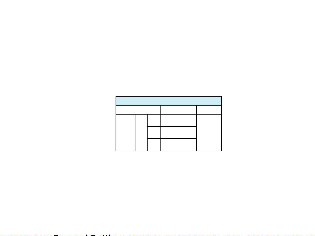
Cycles moyens
Choisissez entre les variantes suivantes:
Cycles moyens (uniquement avec l'option Interpretation)
Séquence de touches Format Confirmation
5 Les cycles moyens ne sont pas imprimés.
4*3 (25 mm/s) + 2*rythme (25 mm/s)
6
Les cycles moyens et deux enregistrements du rythme sont
imprimés à une vitesse d'écriture de 25 mm/s.
ALT 1 ou 2 2
4*3 (50 mm/s) + 2* rythme (25 mm/s)
7
The average complexes are printed out in four groups of three
leads with 2 rhythm leads at a chart speed of 50 mm/s.
6*2 (50 mm/s) + 2*Rhy (25 mm/s)
8
The average complexes are printed out in two groups of six
leads with two rhythm leads at a chart speed of 50 mm/s.
Validez chaque entrée en appuyant sur la touche STOP.
Note: La sélection des dérivations du rythme se fait comme indiqué à la page 29.
Appuyez sur la
touche STOP
AT-2
Mode d'emploi
Page 25
Page 90

Réglage pour l'enregistrement automatique
Mesures de l'ECG et marques de référence
Pour activer la mesure de l'ECG et ajouter ou non les marques de référence aux cycles moyens, faites
les entrées suivantes:
Mesures et Marques (uniquement avec l'option Interpretation)
Séquence de touches Format Confirmation
Le tableau détaillé des valeurs de mesure est supprimé
5
(les valeurs des axes électriques, les intervalles et la
fréquence cardiaque ne sont pas supprimés).
6 Le tableau détaillé des valeurs de mesure est édité.
ALT1ou23
Les marques de référence (début et fin de l'onde P et des
7
complexes QRS, fin de l'onde T) sont omises.
Les marques de référence (début et fin de l'onde P et
8
dess complexes QRS, fin de l'onde T) sont ajoutées aux
cycles moyens.
Validez l'entrée en appuyant sur la touche STOP.
Appuyez sur la
touche STOP.
Page 26
AT-2
Mode d'emploi
Page 91

Réglage pour l'enregistrement automatique
Interprétation
Pour imprimer ou supprimer les indications diagnostiques, procédez ainsi:
Interprétation (uniquement avec l'option interprétation)
Séquence de touches Imprimer Confirmation
l'interprétation est
5
ALT 1 ou 2 4
6
omise
l'interprétation est
imprimée
Validez l'entrée en appuyant sur la touche STOP.
L'option Interpretation est décrite de manière détaillée dans la publication de SCHILLER intitulée Guide
pour les programmes de mesure et d'interpretation - voir plus tard.
Appuyez sur
la touche
STOP
AT-2
Mode d'emploi
Page 27
Page 92

Réglage pour l'enregistrement automatique
Paramètres d'interprétation
Les paramètres d'interprétation permettent de décider si oui ou non certains commentaires seront
ajoutés aux indications diagnostiques. Par ailleurs, on peut définir le groupe d'âge correspondant au
patient (< ou > 30 ans) et sélectionner une sensibilité basse ou haute. La sélection de la sensibilité
basse supprime des résultats d'ECG non spécifiques ce qui peut s'avérer utile pour des enregistrements
réalisés en masse.
Paramètres d'interpretation
Séquence de touches Paramètre Confirmation
1 "Normal" / "Anormal" n'est pas imprimé
2 "Normal" / "Anormal" est imprimé
3 "Rapport non confirmé" n'est pas imprimé
ALT 6
4 "Rapport non confirmé" est imprimé
5 On suppose qu l'âge du patient est <30
6 On suppose que l'âge du patient est >30
7 Sensibilité basse
8 Sensibilité haute
Pressez la
touche STOP
Page 28
AT-2
Mode d'emploi
Page 93

Réglage pour l'enregistrement automatique
Sélection des dérivations du rythme
Les rythmes sont imprimés lorsque vous sélectionnez un format d'impression avec l'enregistrement du
rythme. Vous pouvez choisir deux dérivations du rythme.
Dérivation du rythme
Séquence de touches Dérivation
ALT
Pour selectionner les 2 dérivations du rythme, procédez comme ceci:
3 Dérivation du rythme R1
4 Dérivation du rythme R2
Dérivation d'extrémité
Séquence de touches Dérivation Confirmation
1 I
2 II
ALT3ou48
3 III
4 aVR
5 aVL
6 aVF
Appuyez sur
la touche
STOP
Validez l'entrée en appuyant sur la touche STOP.
AT-2
Mode d'emploi
Dérivations précordiales
Séquence de touches Dérivations Confirmation
1 V1
2 V2
ALT3ou49
3 V3
4 V4
5 V5
6 V6
Appuyez sur
la touche
STOP
Page 29
Page 94

Raccordement du patient
Le AT-2 est fourni avec un câble patient à 10 dérivations comme accessoires standard. Il faut mettre le
câble patient dans la prise désignée par "EKG/ECG", située sur la face latérale de l'appareil et le fixer
en bien serrant les deux vis.
Le AT-2 est classé CF . Cela signifie que le raccordement du patient est entièrement isolé et
protégé contre les décharges de défibrillateurs. La protection anti-défibrillation n'est assuröe que si le
câble patient d'origine de Welch Allyn Schiller (art. n° 80180-0000) est utilisé. Lors de l'enregistrement
des ECGs, il faut veiller à ce que ni le patient, ni les parties conductrices du raccordement du patient ou
des électrodes (également de l'électrode neutre) ne puissent entrer en contact avec d'autres objects
conducteurs (même s'ils sont mis à terre) ou avec des personnes.
Page 30
AT-2
Mode d'emploi
Page 95

Raccordement du patient
La qualité de l'enregistrement dépend tout particulièrement de la préparation de la peau et de la résistance
entre la peau et les électrodes. Plus la résistance de passage entre la surface de la peau et l'électrode
est faible, meilleure sera la qualité de l'enregistrement de l'ECG. Pour cette raison, il faut tenir compte
des instructions suivantes:
1. Il faut que le patient soit détendu et qu'il n'ait pas froid
2. Rasez les poils gênants dans les zones du coprs où seront fixées les électrodes.
3. Nettoyez bien les zones du corps correspondantes à l'aide d'alcool.
4. Commencez par appliquer l'électrode C4 - à hauteur du cinquième espace intercostal, sur
la ligne médio-claviculaire.
Placez maintenant:
n C1 à hauteur du quatrième espace intercostal, au bord droit du sternum
n C2 à hauteur du cinquième espace intercostal, au bord gauche du sternum
n C3 entre C4 et C2
n C6 sur la ligne médio-axillaire gauche, à hauteur du C4
n C5 entre C4 et C6 à la même distance
En respectant ces instructions simples, vous aurez toujours des résultats d'une excellente qualité.
AT-2
Mode d'emploi
Page 31
Page 96

Raccordement du patient
Dérivations standard
CEI AHA
N Noir RL Vert
R Rouge RA Blanc
C1 Blanc / Rouge V1 Marron / Rouge
C2 Blanc / Jaune V2 Marron / Jaune
C3 Blanc / Vert V3 Marron / Vert
C4 Blanc / Marron V4 Marron / Bleu
C5 Blanc / Noir V5 Marron / Orange
C6 Blanc / Violet V6 Marron / Violet
L Jaune LA Noir
F Vert LL Rouge
Page 32
AT-2
Mode d'emploi
Page 97

Enregistrement automatique de l'ECG
En mode automatique, un ECG complet de 12 dérivations est imprimé dans l'un ou l'autre format
d'impression prédéfini. Normalement, les deux formats sont programmés lors de la mise en service de
l'appareil et ils ne devraient pas être modifiés.
Si la touche est appuyée avant l'enregistrement automatique, les niveaux des signaux sont
adaptés pour éviter un chevauchement des amplitudes QRS. En cas d'amplitudes de signaux trop
grandes, la sensibilité est réduite automatiquement à une valeur de 5 mm/mV.
Pour démarrer l'enregistrement dans le format 1, appuyez sur la touche .
Pour imprimer l'ECG dans le 2° format, appuyez sur la touche puis sur .
AT-2
Mode d'emploi
Page 33
Page 98

Enregistrement automatique de l'ECG
L'impression donne les informations suivantes:
- les dérivations de l'ECG (Standard ou Cabrera) dans le format sélectionné
- la sensibilité
- la fréquence cardiaque
- la vitesse de l'enregistrement
- les réglages des filtres
- la zone de données pour l'entrée manuelle des données du patient
et si sélectionné:
- les cycles moyens (uniquement avec l'option Interprétation)
- les intervalles (uniquement avec l'option Interprétation)
- les valeurs des axes (uniquement avec l'option Interprétation)
- l'indice Sokolow (l'indice d'ECG pour des hypertrophies; uniquement avec l'option Interprétation)
- le tableau des vlaeurs de mesure (uniquement avec l'option Interprétation)
- les indications de l'interprétation (uniquement avec l'option Interprétation)
n Pour obtenir un autre rapport imprimé dans le format 1, appuyez sur la touche .
n Pour obtenir un autre rapport imprimé dans le format 2, appuyez sur la touche et puis
sur .
AT-2
Page 34
Mode d'emploi
Page 99

Enregistrement manuel de l'ECG
En mode manuel, l'ECG complet des 12 dérivations est imprimé en format sélectionné avec une
sensitivité de 10 mm/mV. Vous pouvez régler les paramètres d'enregistrement suivants comme bon
vous semble:
n le groupe de dérivation (à l'aide des touche et )
Vous pouvez choisir entre les groupes suivants:
- I, II, III, aVR, aVL, aVF (Cabrera: aVL, I, -aVR, II, aVF, III)
- V1, V2, V3, V4, V5, V6
- II, aVF, III, V2, V4, V5
- V4, V5, V6, V7, V8, V9
n la vitesse d'impression (à l'aide des touches , et )
n la sensibilié (à l'aide des touches , et )
n le filtre myogramme voir page 20.
AT-2
Mode d'emploi
Page 35
Page 100

Enregistrement manuel de l'ECG
Pour démarrer l'enregistrement manuel et l'impression continue, appuyez sur la touche .
Le rapport donne les informations suivantes:
- le groupe de 6 dérivations sélectionné avec leur identification
- la vitesse d'écriture, la sensibilité et le réglage des filtres (si sélectionné) sont indiqués
dans la marge inférieure du rapport.
- la fréquence cardiaque figure en haut sur le rapport.
Si vous appuyez sur la touche , un signal d'étalonnage est imprimé et la ligne de base réalignée.
Pour interrompre l'impression continue, appuyez sur la touche .
ATTENTION:
EN PRÉSENCE D'ARTEFACTS TROP FORTS OU SI UNE ÉLECTRODE S'EST
DÉTACHÉE, L'INDICATION DE LA FRÉQUENCE CARDIAQUE N'EST VALABLE QUE
DANS UNE CERTAINE LIMITE.
Page 36
AT-2
Mode d'emploi
 Loading...