

Page 1
®
140/78140/78
8080
1212
9797
%
HALL, ROBERT E.HALL, RO BERT E. 34561873456187 3:00:06P3:00:06P
AdultAdult Rm 239Rm 23 9
HR/minHR/min NIBP mmHg (102)NIBP mmHg (102)
@2:47P Manual@2:47P Manual
Resp/minResp/min SpO2SpO2
SpO2SpO2 2x2x
II 1mV/cm II 1mV/cm
Propaq
LT
Vital Signs Monitor
Directions for Use
901061 Patient monitor
Software version 1.60.XX
Page 2

ii Welch Allyn Propaq LT Vital Signs Monitor
© 2014 Welch Allyn. All rights are reserved. To support the intended use of the product described in this publication, the
purchaser of the product is permitted to copy this publication, for internal distribution only, from the media provided by Welch
Allyn. No other use, reproduction, or distribution of this publication, or any part of it, is permitted without written permission
from Welch Allyn.
Welch Allyn assumes no responsibility for any injury to anyone, or for any illegal or improper use of the product, that may
result from failure to use this product in accordance with the instructions, cautions, warnings, or statement of intended use
published in this manual.
Welch Allyn, Propaq, Acuity, Smartcuf, and FlexNet are registered trademarks of Welch Allyn. ParamSet is a trademark of
Welch Allyn.
Masimo, SET, LNOP, and LNCS are registered trademarks, and FastSAT and APOD are trademarks, of Masimo Corporation.
Possession or purchase of a Masimo SpO
-equipped monitor does not convey any express or implied license to use the
2
device with unauthorized sensors or cables which would, alone or in combination with this device, fall within the scope of
one or more of the patents relating to this device.
Nellcor and Oximax are registered trademarks of Nellcor Puritan Bennett.
Software in this product is copyright by Welch Allyn or its vendors. All rights are reserved. The software is protected by
United States of America copyright laws and international treaty provisions applicable worldwide. Under such laws, the
licensee is entitled to use the copy of the software incorporated with this instrument as intended in the operation of the
product in which it is embedded. The software may not be copied, decompiled, reverse-engineered, disassembled or
otherwise reduced to human-perceivable form. This is not a sale of the software or any copy of the software; all right, title
and ownership of the software remain with Welch Allyn or its vendors.
For information about any Welch Allyn product, visit http://www.welchallyn.com/about/company/locations.htm.
DIR 80018709 Ver A
Welch Allyn, Inc.
4341 State Street Road
Skaneateles Falls, NY 13153 USA
www.welchallyn.com
Welch Allyn Limited
Navan Business Park
Dublin Road
Navan, County Meath
Republic of Ireland
Page 3

Contents
1 - Introduction .............................................1
iii
Intended use.....................................................1
Symbols ........................................................1
Safety..........................................................4
Controls, indicators, and connectors ..................................8
Features and functions ............................................10
Models ........................................................10
Accessories ....................................................11
USB option .....................................................11
HIPAA considerations .............................................12
2 - Overview of monitor operation ............................13
Turning on the monitor ............................................13
Selecting a language..............................................14
About the charging/communications cradle ............................14
Displaying data ..................................................17
About navigation .................................................31
Menus.........................................................33
About monitor information screens ..................................38
Using demo mode ...............................................40
Power saving ...................................................44
Turning off the monitor............................................44
Communicating with an Acuity Central Station .........................44
About error detection .............................................44
Transporting the monitor with the patient .............................45
3 - Standalone monitoring...................................47
Overview ......................................................47
Preparing for a new patient ........................................47
Continuing to monitor a patient on power-up...........................51
Monitoring ECG and Resp .........................................52
Monitoring SpO2.................................................60
Monitoring blood pressure (NIBP) ...................................65
Changing the default settings.......................................69
To discontinue monitoring .........................................71
4 - Monitoring in communication with Acuity ...................73
About wireless monitoring .........................................73
Establishing communication with Acuity ..............................74
Monitoring a patient outside of network range .........................75
About Acuity message menus ......................................76
5 - Alarms and alerts .......................................81
Overview ......................................................81
Silencing an alarm or alert tone .....................................81
Suspending the alarm tone.........................................82
Changing alarm limits .............................................84
Page 4

iv Contents Welch Allyn Propaq LT Vital Signs Monitor
About ParamSet .................................................85
Responding to an alarm ...........................................85
Responding to an alert ............................................85
About battery charge status ........................................86
Alert messages and status messages ................................87
6 - Storing and reviewing patient data .........................91
Overview ......................................................91
Capturing a data snapshot .........................................91
Reviewing data at the monitor ......................................92
Reviewing data at a PC ............................................95
Reviewing data at Acuity ..........................................95
7 - Printing patient data .....................................97
Overview ......................................................97
Printing ........................................................98
AutoPrint options ...............................................100
8 - Monitor configuration...................................103
Overview .....................................................103
About factory configuration .......................................103
About default configuration .......................................104
About temporary configuration .....................................104
About Acuity-defined configuration .................................104
Parameter configuration matrix ....................................105
9 - PC utility ..............................................113
Introduction....................................................113
Installation.....................................................114
Using the Configuration Utility to configure the monitor .................116
Configuration settings............................................118
About AutoPrint ................................................121
Configuration worksheet ..................................123
Identification ...................................................124
Default Settings ................................................126
Display Settings ................................................128
Mode Settings .................................................131
ParamSet Settings ..............................................133
Feature Enable .................................................135
Authorization...................................................138
10 - Maintenance .........................................139
Recharging the battery ...........................................139
Inspecting and cleaning the monitor and accessories ...................140
Recycling monitor components ....................................141
A - Specifications .........................................143
B - Compliance ...........................................159
Limited warranty .........................................187
Index ...................................................189
Page 5
1
1
Introduction
Intended use
The Propaq LT Series (802LTAN, 802LTAS, 802LT0N, 802LTRN, 802LT0S, and 802LTRS)
monitors are portable devices intended to be used by clinicians and medically qualified
personnel for single- or multiparameter vital-signs monitoring of ambulatory and
nonambulatory patients, including neonate, pediatric and adult patients. These devices
are indicated for ECG, noninvasive blood pressure (NIBP), respiration and SpO2. The most
likely locations for patients to be monitored by these devices are hospital general
medical-surgical, telemetry, and intermediate care floors, hospital emergency
departments, transport, emergency medical services, and other healthcare applications.
The monitors can be used as standalone devices or as devices networked to an Acuity
Central Station (referred to in this manual as ‘Acuity’) through wireless communication
over a Welch Allyn®FlexNet®network.
Federal USA law restricts this device to sale, distribution, or use by or on the order of a
licensed healthcare professional.
Even though this manual describes some monitoring techniques, the monitor is intended
for use only by trained and experienced clinicians who know how to measure and
interpret vital signs.
®
Symbols
Table 1. Directions for use
WARNING Indicates conditions that could lead to illness, injury, or death.
Caution In this manual, indicates conditions that could damage equipment or other property.
Caution On the product, means “Consult the accompanying documentation.”
Page 6
2 Introduction Welch Allyn Propaq LT Vital Signs Monitor
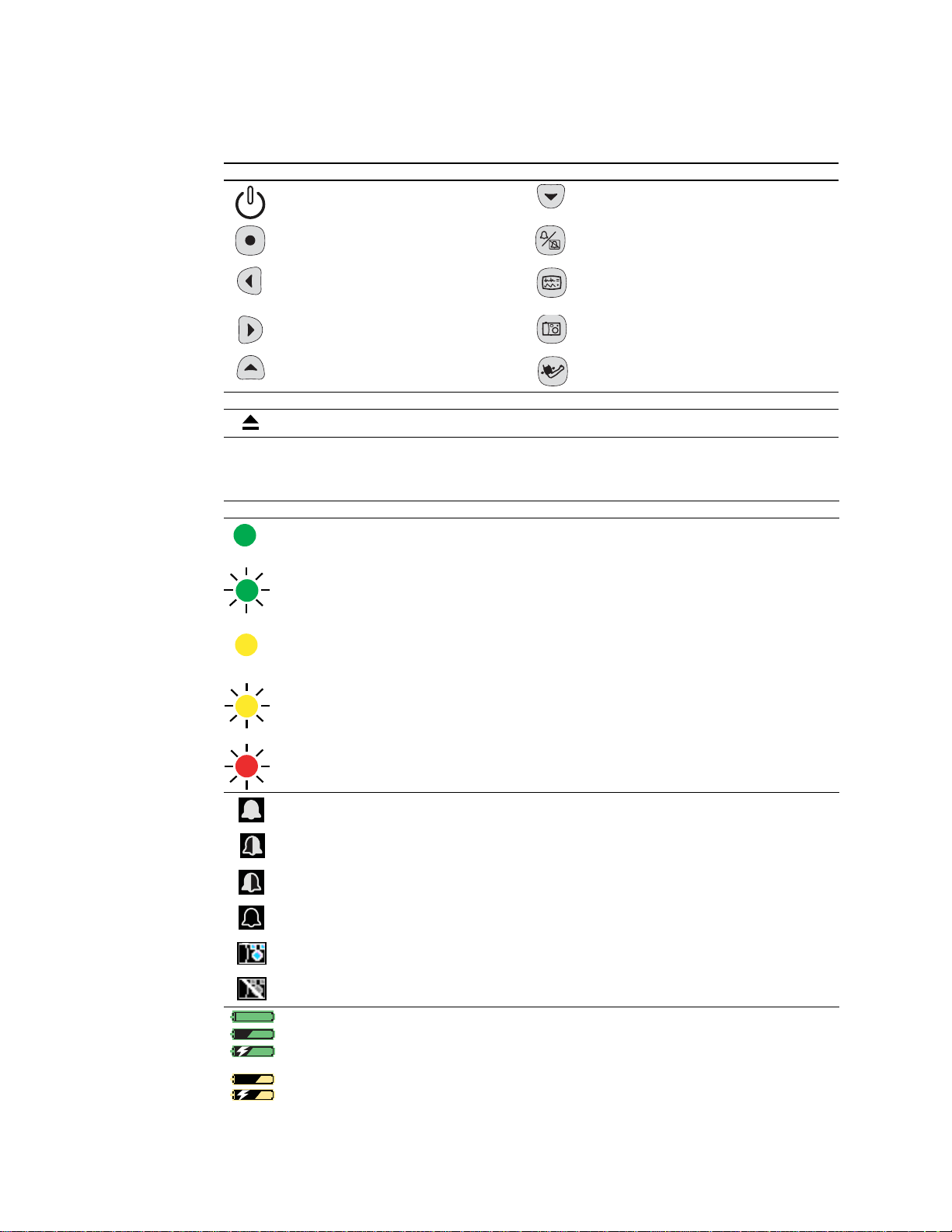
Table 2. Control buttons
Monitor
Power - Turn the monitor power on or off. Down - Move the cursor down to the next display
Action - Act based on what is highlighted.
(See “Using the action button” on page 31.)
Left - Move the cursor left to the next display
item; decrease the parameter value.
Right - Move the cursor right to the next
display item; increase the parameter value.
Up - Move the cursor up to the next display
item.
Cradle
Monitor Release - Press and then hold while removing the monitor from the cradle.
item.
Silence/Reset - Silence the current alarm tone
for 90 seconds or reset a silenced alarm tone.
Display - Cycle to the next configured display
format, or cancel the current control, setup, or
pop-up menu.
Snapshot - Record a 21
and waveform data.
Start/Stop NIBP - Start or stop an NIBP
measurement.
-second period of numeric
Table 3. Status indicators
Monitor
(green) Monitoring normally (no active alarms or alerts).
Connection to Acuity is confirmed and patient identification is confirmed. (Wireless only, Acuity enabled.)
(green flashing) Monitoring normally (no active alarms or alerts). (Standalone only.)
Patient confirmed, and monitor then intentionally disconnected. (Wireless only, Acuity enabled.)
(yellow) At least one alarm is disabled.
Monitor disconnected, connecting or connected; patient not confirmed. (Wireless only, Acuity enabled.)
(yellow flashing) Equipment alert.
Acuity message windows. (Wireless only, Acuity enabled.)
(red flashing) Patient alarm.
Upper and lower alarm limits for this parameter are on.
The upper alarm limit for this parameter is on and the lower is off.
The upper alarm limit for this parameter is off and the lower is on.
Upper and lower alarm limits for this parameter are off.
A snapshot exists for this period.
The snapshot for this period has been replaced with a more recent snapshot.
(green) The battery is fully charged.
The battery is partially full.
The battery is partially full and is charging.
(yellow) The battery is low.
The battery is low and is charging.
Page 7
Directions for Use Introduction 3
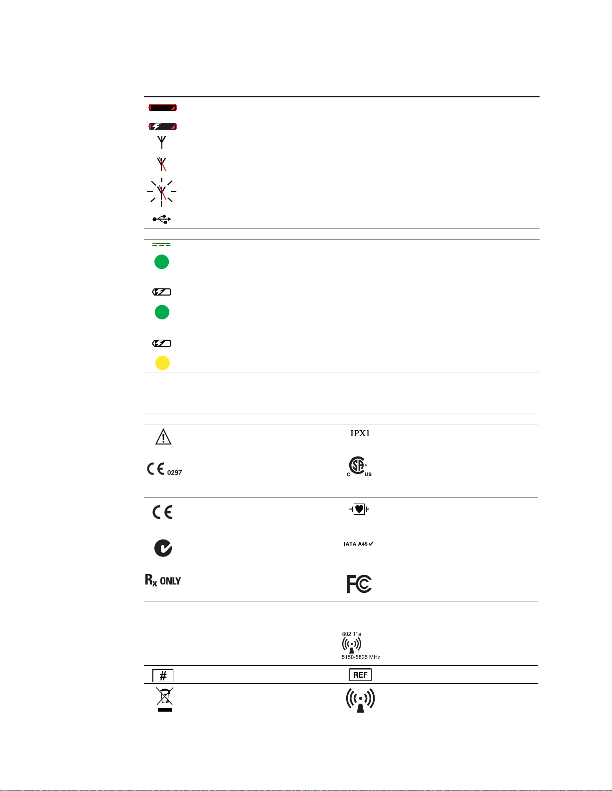
Table 3. Status indicators (continued)
(red) The battery is near failure; the monitor will shut down soon. If this indicator appears
while the monitor is in the cradle, the battery cannot be charged and must be replaced.
The battery is near failure and is charging. The monitor will shut down if removed from the cradle.
The monitor is communicating wirelessly with the network and with Acuity. (Wireless only, Acuity
enabled.)
The monitor is not communicating with the wireless network. (Wireless only, Acuity enabled.)
(Flashing) The monitor is communicating with the network but is not communicating with Acuity.
(Wireless only, Acuity enabled.)
The monitor is communicating by USB cable with a PC.
Cradle
(green) Cradle is powered.
(green) Monitor battery is charging.
NOTE: When the battery is fully charged, this indicator is not lit.
(yellow) Cradle fault or battery fault.
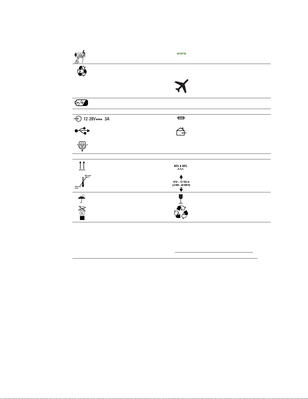
Table 4. Labels
Proceed with caution. If in doubt, refer to the
accompanying documentation.
The monitor or accessory meets all essential
requirements of the European Medical Device
Directive 93/42/EEC for a Class II-b product.
The monitor or accessory meets all essential
requirements of the European Medical Device
Directive 93/42/EEC for a Class I product.
Australian registered importer. Hazard Class 9, IATA/ICAO (International Air
N344
Professional use only This device complies with the 47 CFR Part 15
FCC ID: PGUWA11A07
IC:4168a-WA11A07
See the accompanying manual. Non-ionizing electromagnetic radiation. This
Reorder number Product identifier
Monitor
Enclosure protection: Drip
per EN60529:1991.
The monitor is certified by the Canadian
Standards Association International to comply
with applicable US and Canadian medical
safety standards.
Type CF patient connections, isolated for direct
cardiac application and protected against
defibrillation.
Transport Association/International Civil
Aviation Organization).
radiated and conducted emissions
requirements.
This device complies with FCC and Industry Canada requirements for international
radiators (802.11 wireless).
device contains an approved RLAN module of
frequency 5150-5825 MHz.
-proof. Class IPX1
Recycle the monitor, cradle, and battery
separately from other waste. (Refer to
www.welchallyn.com/weee for collection-
point and additional information.)
Non-ionizing electromagnetic radiation. This
device contains an approved RLAN module of
frequency 2402-2480 MHz. (Wireless only,
Acuity enabled; see “EMC” on page 162.)
Page 8
4 Introduction Welch Allyn Propaq LT Vital Signs Monitor
Table 4. Labels
Li ++
High voltage. Do not touch during
defibrillation.
Recycle the battery separately from other
disposables.
Lithium
-ion battery. This monitor (2.4 GHz) is approved for use
Rechargeable battery
Cradle
Power in (DC). Fuse replacement specification.
T3A/250V
USB cable connector. For indoor use only.
Input power (DC) pin pattern.
Product packaging
Store this way up. Humidity limit.
Temperature limits. Altitude limits.
Rain protection required. Contents are fragile.
Direct current.
Battery replacement specification.
during all phases of flight aboard U.S. Army
aircraft. AWR: MIL STD: 461E. Army: CE101,
CS101, T, CS115, S116, RE102, RE103.
Safety
Stacking limit. Recycle the packaging material.
The monitor is safe for patients and clinicians when used in accordance with the
instructions and with the warning and caution statements presented in this manual.
All personnel must read and understand all warning and caution statements
presented in this manual before using the monitor.
• Failure to understand and observe any warning statement in this manual could
lead to patient injury, illness, or death.
• Failure to understand and observe any caution statement in this manual could
lead to equipment damage or loss of patient data.
Page 9

Directions for Use Introduction 5
General warnings
These statements apply to all aspects of patient monitoring. Statements which apply
specifically to one aspect of monitoring, such as NIBP or SpO2monitoring, are presented
in the corresponding sections of the manual.
WARNING Many environmental variables, including patient physiology and
clinical application, can affect the accuracy and performance of the monitor. The
clinician must verify all vital-signs information prior to patient intervention.
WARNING Always check the patient mode (adult, pediatric, or neonate) when
monitoring a new patient. The patient mode determines default alarm limits and
internal algorithm settings. Make sure the monitor has settings that are
appropriate before monitoring the patient.
WARNING Make sure Acuity patients, and especially those prone to
arrhythmias, are kept under close surveillance. While monitoring patients with
Acuity, the clinician must review all clinical data before implementing therapy. As
with all computerized arrhythmia analysis systems, Acuity cannot replace skilled
care and proper surveillance by a clinician.
WARNING It is possible for Acuity alarms, alerts, or other events to go
unnoticed if clinical personnel are not present at Acuity or if interruptions occur in
power or system operations. To help reduce this possible occurrence, Acuity
must be installed with redundant power supplies and redundant means of
operator surveillance, such as secondary Acuity Central Stations and hallway
message panels.
WARNING The monitor might not meet its performance specifications if stored
or used outside the specified temperature and humidity ranges.
WARNING Use of respiration monitoring by impedance pneumography can
affect the operation of some pacemakers. If pacemaker operation is affected, turn
off respiration pneumography. (See Figure 63 on page 57.)
WARNING Do not connect more than one patient to a monitor.
WARNING Do not connect more than one monitor to a patient.
WARNING During defibrillation, keep discharge paddles away from the monitor
ECG lead wires, electrodes, any other monitor sensors, and other conductive
parts in contact with the patient.
WARNING Do not operate this product in the presence of flammable
anaesthetics or other flammable substances in combination with air or
oxygen-enriched environments. Failure to observe this warning can result in an
explosion.
WARNING Do not use the monitor in a Magnetic Resonance Imaging (MRI)
suite or a hyperbaric chamber. Such use can cause fire or explosion resulting in
patient injury and monitor damage.
WARNING Do not operate this monitor near equipment that emits strong
electromagnetic or radio-frequency signals. Electronic equipment of this type can
cause electrical interference with monitor operation, which can distort the ECG
signal and prevent accurate rhythm analysis.
Page 10

6 Introduction Welch Allyn Propaq LT Vital Signs Monitor
WARNING To comply with Federal Communications Commission (FCC) RF
exposure requirements and to avoid exposure to radio-frequency (RF) radiation,
always use the monitor in accordance with the operating conditions and
instructions provided in this manual.
WARNING Pacemaker signals can differ from one pacemaker to the next. The
Association for Advancement of Medical Instrumentation (AAMI) cautions that “in
some devices, rate meters may continue to count the pacemaker rate during
occurrences of cardiac arrest or some arrhythmias. Do not rely entirely upon rate
meter alarms. All pacemaker patients should be kept under close or constant
observation.” See “Pacer pulse rejection” on page 145 for disclosure of the
pacemaker pulse rejection capability of this instrument.
WARNING Use only accessories approved by Welch Allyn. The use of any other
accessories can result in inaccurate patient data, can damage the equipment, and
can void your product warranty. Refer to the accessory list or
www.welchallyn.com.
WARNING Always use accessories according to the standards of your facility
and according to the manufacturer's directions.
WARNING Use of Masimo
®
LNOP®sensors/cables will not provide protection in
accordance with IEC defibrillation standards when used with this device.
WARNING Use only ECG cables supplied or specified by Welch Allyn. Use of
any other ECG cables can negate defibrillator protection and can create a risk of
patient injury due to shock.
WARNING Frequently inspect—electrically and visually—all cables, sensors, and
electrode wires. Replace any damaged cables, sensors or wires. Failure to
properly inspect and keep in excellent working order all cables, sensors, and
electrode wires can result in hazards to patients and to equipment failure and
damage.
WARNING Always properly connect the electrosurgery return circuit. Improper
circuit connection can cause current to return through monitor electrodes and
probes, creating a burn hazard for patients.
WARNING Always keep patient motion to a minimum. Motion artifact can cause
inaccurate measurement of patient vital signs.
WARNING Carefully route and secure patient cabling, using the supplied
garment clips. Improperly routed and secured cabling can cause the patient to
become entangled in the cables, creating a strangulation hazard.
WARNING When the patient is wearing the monitor or being transported by
stretcher with the monitor connected, always take care to position the monitor
carrying straps on the patient. Be certain that the straps do not and cannot cross
the neck or throat and cause choking, and the straps do not restrict movement of
the patient’s arms or legs.
WARNING Never use a monitor that is not working properly. If the monitor is not
working properly, patient waveforms might be inaccurate or might not be
displayed.
WARNING If the monitor is damaged, or if you see any indication that the
monitor is not operating properly, disconnect it from the patient. Do not return it
to service until it has been inspected and, if necessary, repaired by qualified
service personnel.
Page 11

Directions for Use Introduction 7
WARNING This wireless medical device was tested and, when used with a
metal-free accessory between the monitor and the patient, complies with FCC
RF Exposure (SAR) guidelines. The use of accessories containing metal may not
ensure compliance with FCC RF exposure guidelines. Specific Absorption Rate
(SAR) is a measurement of radio frequency energy. The FCC permits a maximum
SAR value of 1.6 mW/g. The highest SAR value for this patient monitor, when
worn by a patient in accordance with the directions for use, is 0.560 mW/g.
WARNING High-power radars are allocated as primary users of the bandwidth
between 5.25 GHz and 5.35 GHz and between 5.65 GHz and 5.85 GHz. These
radars can cause interference with this device and can damage this device.
WARNING Do not use the pulse oximeter as a replacement or substitute for
ECG-based arrhythmia analysis.
WARNING The bedside patient monitor is the primary alarming source for the
patient and a central station is a backup alarm source. The central station is only
as reliable as its network and should be relied on only as a backup alarming
device.
WARNING The leading cause of patient death or serious injury reported with the
use of patient monitoring equipment is failure to respond to alarms notifying the
user of an adverse change in patient condition. If you are relying on visual alarm
notifications, maintain a clear line of sight and remain within 4 meters of the
monitor or the central station. If you are relying on audio alarm notifications, make
sure that you can hear audio alarms from where you are. Set the volume as
needed considering the environment and ambient noise levels. Verify that the
alarm is audible to a clinician working at the maximum distance from the monitor
or central station.
General cautions
WARNING Auto-reboots occur and wireless connection is occasionally
disrupted. During this period, the bedside monitors continue to provide their
primary alarming functions. Auto-reboots occur infrequently, due to poor
environmental conditions. Failure to perform preventative maintenance can
increase the frequency of occurrence.
WARNING False alarms may occur in some situations. You must understand
and address the cause of the false alarms whenever possible to eliminate the
possibility of repeated false alarms and alarm fatigue, which might result in a
failure to respond to an actual alarm situation.
Caution Do not autoclave the monitor.
Caution Autoclave accessories only if the manufacturer's instructions clearly
direct you to do so. Many accessories can be damaged by autoclaving.
Caution Changes or modifications not expressly approved by Welch Allyn could
void the purchaser’s authority to operate the equipment.
Caution This product contains no user-serviceable components. Any
unauthorized changes to the product invalidate Welch Allyn’s warranty and also
invalidate all applicable regulatory certifications and approvals.
Page 12
8 Introduction Welch Allyn Propaq LT Vital Signs Monitor
14040/7878
80
12
97
%
HALL, RO BERT E.
3456187
3:00:06P
Adult ,
Rm 23 9
HR/min
NIBP mmHg (102)
@2:47P Manual
Resp/min
SpO2
SpO22x2x
II 1mV/cm
14040/7878
80
12
97
%
HALL, RO BERT E.
3456187
3:00:06P
Adult ,
Rm 23 9
HR/min
NIBP mmHg (102)
@2:47P Manual
Resp/min
SpO2
SpO22x2x
II 1mV/cm
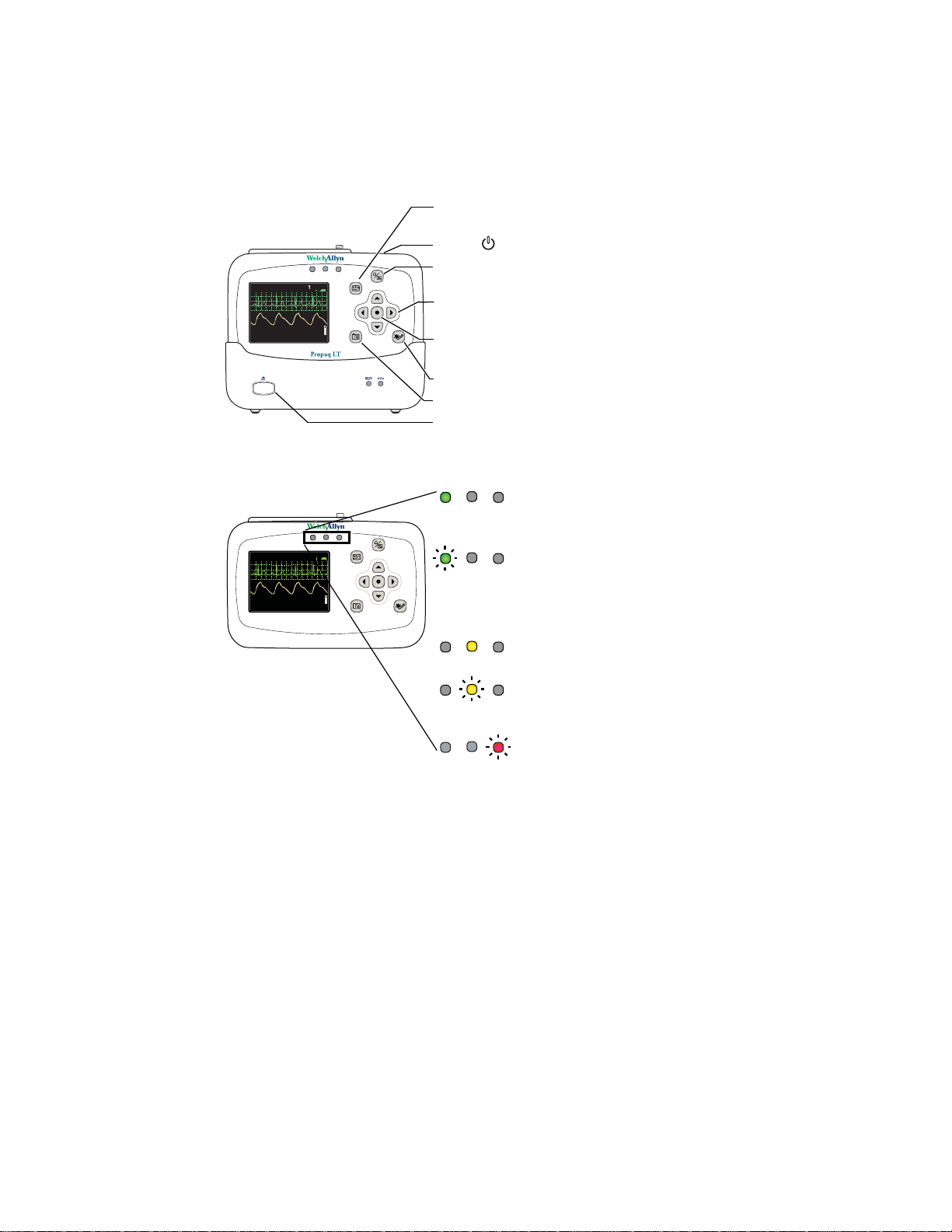
Controls, indicators, and connectors
Figure 1. Controls
HALL, ROBERT E.
3456187
3:00:06P
Adult,
II 1mV/cm
SpO2
HR/min
Rm 239
12
80
NIBP mmHg (102)
@2:47P Manual
Resp/min
97
SpO2
Figure 2. Indicators: Monitor
HALL, ROBERT E.
3456187
3:00:06P
Adult,
II 1mV/cm
SpO2
HR/min
Rm 239
12
80
NIBP mmHg (102)
@2:47P Manual
Resp/min
97
SpO2
Propaq LT
Display Cycle to the next configured display format, or cancel
the current control, setup, or pop-up menu.
Power Turn the monitor power on or off.
Silence/Reset Silence the current alarm tone for 90 seconds or reset a
silenced alarm tone.
Arrows Move the display cursor up, down, right, or left to
highlight an item; change parameter values.
Action Act based on what is highlighted.
(See “Using the action button” on page 31.)
NIBP Start/Stop Start or stop an NIBP measurement.
Snapshot Record 21 seconds of numeric and waveform data.
Monitor release Release the monitor from the cradle.
Green Connection to Acuity is confirmed and patient
identification is confirmed.
(Wireless only, Acuity enabled.)
Green Monitoring normally; no active alarms or alerts.
(flashing) (Standalone.)
Patient was confirmed and the monitor was then
intentionally disconnected.
(Wireless only, Acuity enabled.)
Yellow At least one alarm limit is disabled. (Standalone.)
Not monitoring (Wireless only, Acuity enabled).
Yellow Equipment alert. (Standalone.)
(flashing) Acuity message windows.
(Wireless only, Acuity enabled.)
Red Patient alarm.
(flashing)
Page 13

Directions for Use Introduction 9
14040/7878
80
12
97
%
HALL, RO BERT E.
3456187
3:00:06P
Adult ,
Rm 23 9
HR/min
NIBP mmHg (102)
@2:47P Manual
Resp/min
SpO2
SpO22x2x
II 1mV/cm
14040/7878
80
12
97
%
HALL, RO BERT E. 3456187 3:0 0:06P
Adult , Rm 239
HR/min
NIBP mmHg (102)
@2:47P Manual
Resp/min
SpO2
SpO2 2x
II 1mV/cm
Figure 3. Indicators: cradle
12
80
HR/min
NIBP mmHg (102)
@2:47P Manual
Resp/min
97
SpO2
Off Battery is full or monitor is not in the cradle
Green Battery is charging
HALL, ROBERT E.
II 1mV/cm
SpO2
80
HR/min
NIBP mmHg (102)
@2:47P Manual
3456187
3:00:06P
Adult,
Rm 239
12
97
Resp/min
SpO2
Yellow Cradle fault or battery fault
Green Cradle is connected to power
Off Cradle is not connected to power,
or cradle fault
Figure 4. Connectors: monitor
SpO2sensor connector
ECG/Resp cable connector
NIBP hose connector
Figure 5. Connectors: cradle
Strap connectors
Power and data connector
(from the cradle)
Monitor power and data connector
Fuse holder
USB connector for data to
and from the PC (optional)
Power (DC) input connector
Page 14

10 Introduction Welch Allyn Propaq LT Vital Signs Monitor
Features and functions
• Monitoring of neonate, pediatric and adult patients
• Display of ECG, SpO2, and Resp waveform traces
• Accurate reading of NIBP in the presence of motion artifact, using Welch Allyn’s
patented Smartcuf®motion-tolerant technology
• SpO2monitoring with advanced technology for accuracy under conditions of low
perfusion
• Configurable adjustments to alarm limits with ParamSet™technology
• Standalone operation with local patient alarms and equipment alerts
• Optional two-way wireless communication within a Welch Allyn FlexNet network,
providing monitoring and remote control at an Acuity Central Station
• Color LCD for display of numerics and waveform data
• Configurable display formats and monitoring capabilities
• Internal antenna
• Rechargeable lithium-ion battery
• Weight of approximately 2 pounds (0.9 kg)
• Durability
• Tolerance of brief exposure to water
• HIPAA support
• Error detection
Models
The monitor is available in two standalone models and two wireless models.
Feature Model
3-lead and 5-lead ECG x x x x x x
Respiration rate (Resp) x x x x x x
Masimo SpO
Nellcor
Noninvasive blood pressure (NIBP) x x x x x x
802.11a (5-GHz) radio for FlexNet wireless
communication with Acuity
802.11 FHSS (2.4-GHz) radio for FlexNet
wireless communication with Acuity
Cradle to recharge the monitor battery x x x x x x
USB Option Option Option Option Option Option
Upload patient data from the monitor to a PC
and download custom monitor configurations
from a PC to the monitor
2
®
SpO
2
802LTAN
Option Option Option Option Option Option
Model
802LT0N
xxx
xx
Model
802LTRN
xx
Model
802LTAS
Model
802LT0S
xxx
Model
802LTRS
Page 15

Directions for Use Introduction 11
Accessories
The following accessories are available for use with the monitor and the cradle:
• Large Color Display Interface and cables
• Propaq LT Monitor PC Utility software (CD)
• Propaq LT Monitor Service Manual (CD)
• Propaq LT Monitor Directions for Use (CD)
• Patient carry strap
• Patient wearable strap
• Transport stretcher strap
• Connector panel plugs
• SpO2cables and sensors
• 3-lead and 5-lead ECG cables and cable extensions
• ECG electrodes
• NIBP hoses and cuffs
• Battery pack
• AC power adapter
WARNING Use only accessories approved by Welch Allyn. The use of any other
accessories can result in inaccurate patient data, can damage the equipment, and
can void your product warranty. Refer to the accessory list or
www.welchallyn.com.
For ordering information, contact Welch Allyn (see page ii).
USB option
The monitor can be purchased with the optional USB data transfer capability, which
enables communication between the monitor and a PC. (See “About the USB data
transfer option” on page 15.)
WARNING Always use accessories according to your facility’s standards and the
manufacturer’s recommendations.
Page 16

12 Introduction Welch Allyn Propaq LT Vital Signs Monitor
HIPAA considerations
Each medical facility is responsible for creating and enforcing policies and procedures to
guarantee compliance with the regulations defined in 45 CFR 160-164 of the Health
Insurance Portability and Accountability Act (HIPAA) of 1996.
The Propaq LT Monitor, the Large Color Display Interface, the Propaq LT Monitor
Configuration Utility, and the Propaq LT Monitor AutoPrint Utility incorporate security
features that support your implementation of the HIPAA requirements for ensuring that
patient information is kept private and confidential.
Monitor
• Clinicians can lock the monitor display to prevent the display of patient vital signs. For
patient protection when the monitor display is locked, the display is restored instantly
in the event of a button press (unless button-pad lock-out is enabled), an alarm or an
alert.
• Clinicians can lock the monitor buttons to prevent any unauthorized access to the
monitor controls. To protect the patient when the buttons are locked, access to the
buttons is restored instantly in the event of an alarm or an alert.
• No physiological data transmitted by radio from the monitor is in clear text. All data
sent is encoded using Welch Allyn's proprietary PSI Communications Protocol and
can only be decrypted by a Welch Allyn Acuity Central Station residing on the local
Welch Allyn FlexNet network. By default, data transmitted using the 802.11a
standard is also encrypted using AES (Advanced Encryption Standard).
Configuration utility
The Configuration Utility never contains patient data.
AutoPrint utility
• All patient data is stored in a Welch Allyn proprietary data format which is readable
only by machine.
• All patient data is deleted from the PC when it is sent to the printer.
Page 17

13
Application Version 1.00.00
Bootcore Version 1.00.00
Propaq
®
LT
Diagnostics in progress
Welch Allyn 2005
Select ( ) to Start a New Patient.
No data saved.
Start New Patient
Info
Demo
Portland Westside Hospital
Emergency Department
Select ( ) to delete data
and start a new patient.
Portland Westside Hospital
Emergency Department
Note!
There is patient data stored for
Hall, Robert E. ID: 3456187
Start New Patient
Continue Patient
Info
Demo
2
Overview of monitor operation
Turning on the monitor
The monitor runs through an operational self-test each time it is powered on. Always
verify that it follows the power-on sequence shown below. When Step 3 completes as
described, the monitor has verified that the visual and audible alarm indicators are
working properly. If Step 4 does not complete as described, remove the monitor from
service and have it examined by a qualified service person.
To turn on the monitor
1. Press and hold until a tone sounds.
2. A tone sounds as the green, yellow, and red lights turn on and off. This occurs twice.
3. The splash screen appears, identifying the product and displaying the message
“Diagnostics in progress”. The green light turns on and off quickly while the low tone
sounds, the yellow light turns on and off quickly while the medium tone sounds, and
the red light turns on and off quickly while the loud tone sounds.
Figure 6. Splash screen
Propaq
LT
Diagnostics in progress
Application Version 1.00.00
Bootcore Version 1.00.00
c
Welch Allyn 2005
4. The splash screen is replaced by one of the power-on screens shown here:
Figure 7. Power-up screens
Portland Westside Hospital
Emergency Department
No data saved.
Select ( ) to Start a New Patient.
Start New Patient
To start monitoring from this point, see “Standalone monitoring” on page 47. To practice
Info
Demo
Portland Westside Hospital
Emergency Department
There is patient data stored for
Hall, Robert E. ID: 3456187
Select ( ) to delete data
Start New Patient
and start a new patient.
Note!
Continue Patient
Info
Demo
using the monitor, see “Using demo mode” on page 40.
Page 18

14 Overview of monitor operation Welch Allyn Propaq LT Vital Signs Monitor
English
Deutsch
Français
Español
Italiano
Polski
Nederl
Svenska
Português
Japanese
Selecting a language
To change the language of the monitor interface
1. If the monitor power is on, press to turn it off.
2. Press to turn the monitor power on.
3. Immediately after pressing , and before any screen appears, simultaneously press
and . Keep the buttons pressed until the language selection screen appears.
Figure 8. Language selection screen
English
Deutsch
Français
Español
Italiano
Polski
Nederl
Svenska
Português
Japanese
4. Press , , , and to highlight the language you wish to use.
5. Press .
Power-on continues in the selected language.
Note
If you select French, HR/PR alarm limits cannot be turned off unless you go
through the service menus to change this setting. If you do change this setting,
the change stays in effect through power cycles.
For information about using the service menus, refer to the Propaq LT Monitor
Service Manual (810-1811-XX).
The monitor always powers on in this language until the setting is changed again. The
setting can be changed again only if one of the following occurs:
• This procedure is repeated.
• A new configuration is downloaded from a PC. (See “Using the Configuration
Utility to configure the monitor” on page 116).
• A new configuration is downloaded from Acuity.
About the charging/communications cradle
When the charging/communication cradle (the cradle) is attached to AC power (or to
vehicle DC power) and the monitor is seated in the cradle, the cradle does the following:
• Recharges the monitor battery, whether patient monitoring is occurring or not.
• Powers the monitor, conserving the charge on the monitor battery.
• (If the cradle has the USB data transfer option) enables data transfer between a
PC and a monitor. See “About the USB data transfer option” on page 15.
Page 19

Directions for Use Overview of monitor operation 15
14040/7878
80
12
97
%
HALL, RO BERT E.
3456187
3:00:06P
Adult ,
Rm 23 9
HR/min
NIBP mmHg (102)
@2:47P Manual
Resp/min
SpO2
SpO22x2x
II 1mV/cm
WARNING Never download a configuration file to the monitor while you are
monitoring a patient with the monitor in the cradle.
• Communication with the network (and Acuity) is interrupted if you download
a configuration to the monitor or upload patient data from the monitor.
• Changing the monitor configuration shuts down the monitor and deletes all
patient data from the monitor.
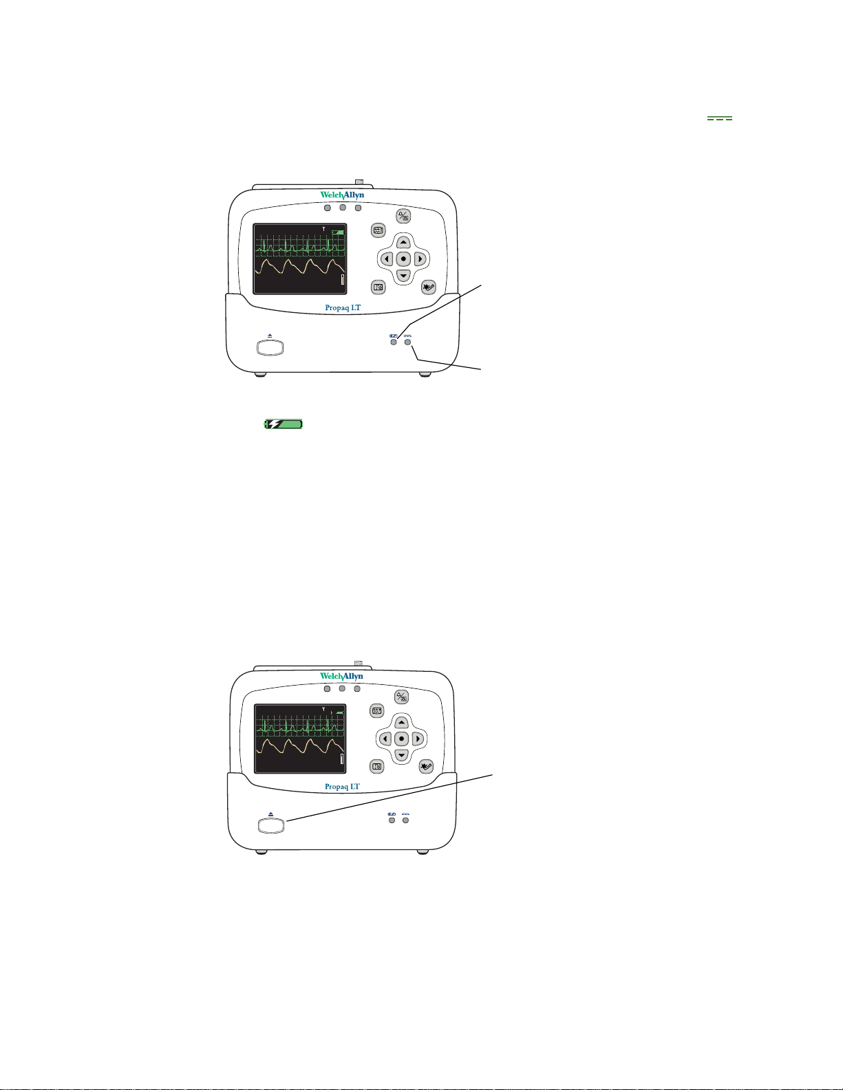
Figure 9. Monitor and cradle
Monitor
HALL, ROBERT E.
3456187
3:00:06P
Adult,
II 1mV/cm
SpO2
HR/min
Rm 239
12
80
NIBP mmHg (102)
@2:47P Manual
Resp/min
97
SpO2
Cradle
The cradle is intended to hold the monitor when the patient is in bed or is otherwise
stationary. The cradle can sit on a flat surface near the patient or attach to the bed rail
(using the bed-rail hook).
If the monitor is in the cradle and the AC power adapter is connected to the cradle, the
monitor runs on AC power rather than battery power. This keeps the monitor battery at full
charge so that the monitor can then run on battery power when it is removed from the
cradle to accompany the patient away from the bed.
The cradle can be connected to AC power at all times, whether the monitor is present
or not.
About the USB data transfer option
A cradle configured with the optional USB communication port and connected to a PC
with the Propaq LT Configuration Utility and the Propaq LT AutoPrint Utility can be used
for the following:
• Creating custom monitor configurations on the PC and downloading them to any
number of monitors. (See “Monitor configuration” on page 103.)
• Uploading the configuration file from the monitor to the PC.
• Uploading patient data from the monitor to the PC for printing. (See “Printing
patient data” on page 97.)
Setting up the cradle
1. Place the cradle on a table or shelf, or hang it on a bed rail.
WARNING Place the cradle so that it cannot fall on the patient.
Caution Locate the cradle near the patient but not so close that it interferes
with patient care.
Page 20
16 Overview of monitor operation Welch Allyn Propaq LT Vital Signs Monitor
14040/7878
80
12
97
%
HALL, ROBERT E .
345618 7
3:00:0 6P
Adul t,
Rm 2 39
HR/min
NIBP mmHg (102)
@2:47P Manual
Resp/min
SpO2
SpO22x2x
II 1mV/cm
14040/7878
80
12
97
%
HALL, ROBERT E .
345618 7
3:00:0 6P
Adul t,
Rm 2 39
HR/min
NIBP mmHg (102)
@2:47P Manual
Resp/min
SpO2
SpO22x2x
II 1mV/cm
2. Connect the AC adapter to an AC power outlet and to the cradle. The indicator
(green) on the front of the cradle indicates that the AC power adapter is connected.
Figure 10. Cradle status indicators
HALL, ROBERT E.
II 1mV/cm
SpO2
80
HR/min
NIBP mmHg (102)
@2:47P Manual
3456187
3:00:06P
Adult,
Rm 239
12
97
Resp/min
SpO2
3. Insert the monitor into the cradle. When the monitor is properly seated, it clicks into
place. (green) on the cradle indicates that the monitor battery is charging. (See
“Recharging the battery” on page 139.)
Note
The monitor can be inserted into the cradle when power is on or off. If monitor
power is on, inserting the monitor in the cradle or removing the monitor from the
cradle does not interrupt patient monitoring.
Removing the monitor from the cradle
To remove the monitor, depress the release button on the front of the cradle. With the
button depressed, hold the cradle securely with one hand, grasp the monitor firmly with
the other hand, and lift the monitor out.
Green Monitor battery charging
Yellow Battery or charger failed
(Indicates either that the temperature of
the battery pack is out of range or that
service is required.)
Green AC power connected
Figure 11. Monitor release button
HALL, ROBERT E.
II 1mV/cm
SpO2
80
HR/min
NIBP mmHg (102)
@2:47P Manual
3456187
3:00:06P
Adult,
Rm 239
12
97
Resp/min
SpO2
Monitor release button
Page 21
Directions for Use Overview of monitor operation 17
140/78
80
12
97
%
HALL, ROBERT E.
3456187
3:00:06P
Adult
Rm 239
HR/min
NIBP mmHg (102)
@2:47P Manual
Resp/min
SpO2
SpO22x2x
II 1mV/cm
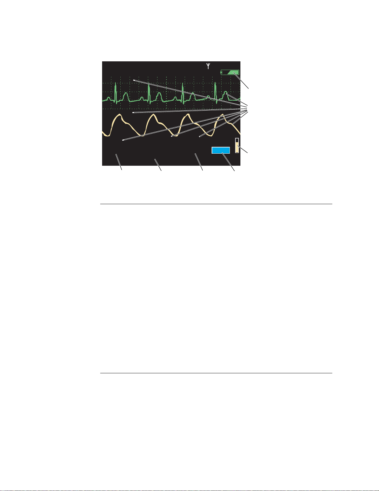
Displaying data
Patient vital signs appear on the 3.5-inch (diagonal measurement) monitor display and
optionally on the Large Color Display screen.
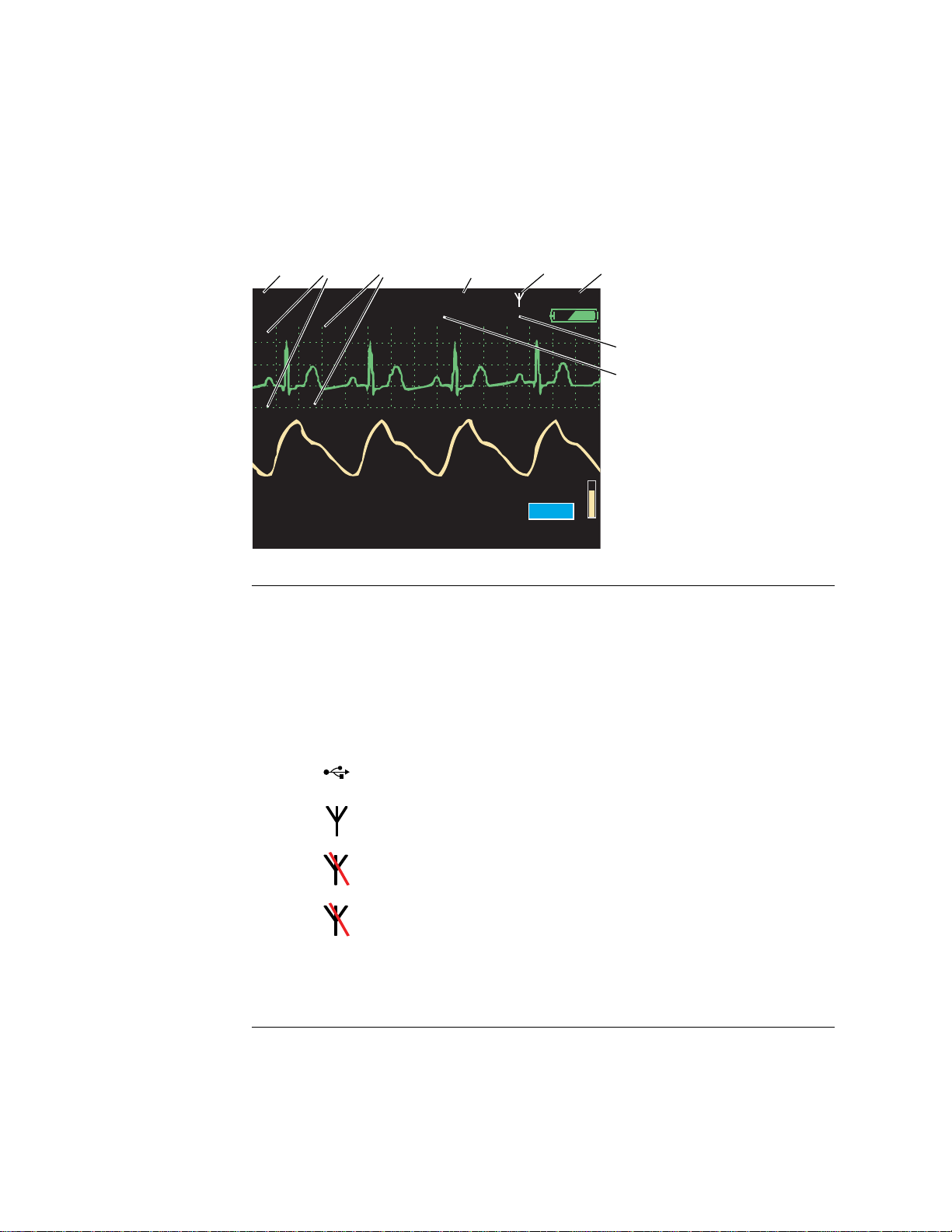
Figure 12. Components of the vital-signs display (A)
1
23 4 56
HALL, ROBERT E.
II 1mV/cm
SpO2
80
HR/min
0
Patient name (if available)
1
Waveform source
2
Waveform display scale
3
Patient ID (if available)
4
Connection status icon
5
3456187
Adult
140/78
NIBP mmHg (102)
@2:47P Manual
(blank) Connectivity not enabled.
Rm 239
12
Resp/min
3:00:06P
7
8
97
SpO2
Time of day
6
Patient room number
7
Patient mode
8
The monitor is communicating via USB cable with a PC. (Wireless monitor only, Acuity
enabled.)
The monitor is communicating with the network and with Acuity.
(Wireless monitor only, Acuity enabled.)
Flashing — the monitor is communicating with the network but not with Acuity.
(Wireless monitor only, Acuity enabled.)
Steady — the monitor is not communicating with the network.
(Wireless monitor only, Acuity enabled).
Page 22
18 Overview of monitor operation Welch Allyn Propaq LT Vital Signs Monitor
140/78
80
12
97
%
HALL, ROBERT E.
3456187
3:00:06P
Adult
Rm 239
HR/min
NIBP mmHg (102)
@2:47P Manual
Resp/min
SpO2
SpO22x2x
II 1mV/cm
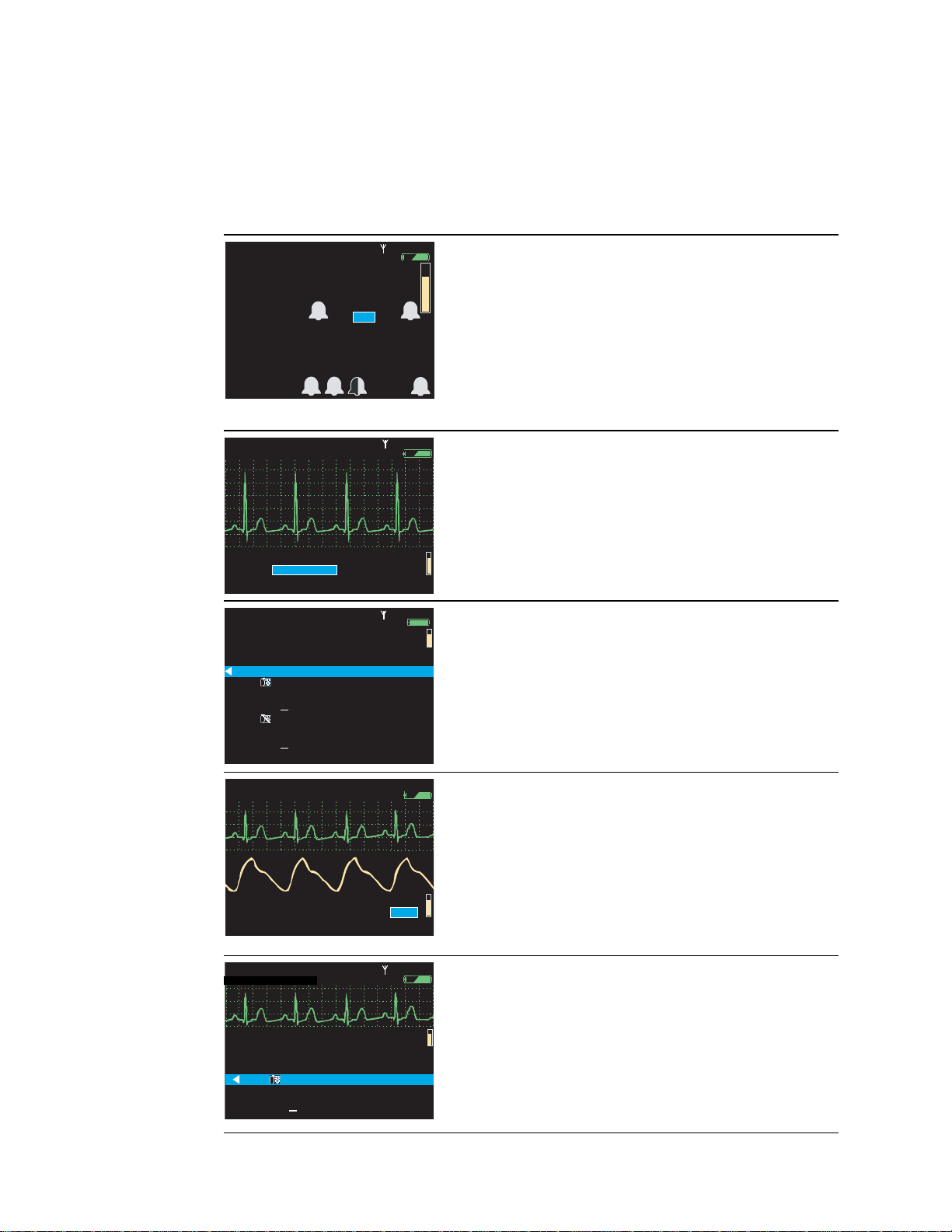
Figure 13. Components of the vital-signs display (B)
HALL, ROBERT E.
II 1mV/cm
SpO2
80
HR/min
9
10
140/78
NIBP mmHg (102)
@2:47P Manual
15 14 13 12
Battery status (See Table 3, “Status indicators” on page 2.)
green partially to fully charged
yellow nearly discharged
red discharged; the monitor will shut down soon
Color-coded waveforms, ECG Lead identifiers, and vital-signs numerics
Adult
3456187
Rm 239
12
Resp/min
3:00:06P
97
SpO2
9
10
11
Green
Cyan
Purple
Yellow
SpO2pulse amplitude
11
SpO2numeric data
12
Respiration rate numeric data
13
NIBP numeric data
14
HR (heart rate) is displayed if ECG is active.
15
PR (pulse rate) is displayed if ECG is not active and SpO
The monitor indicates an HR/PR measurement outside the measurable range as follows:
--- out
+++ out
??? undetermined
ECG and HR/PR
NIBP
Resp
SpO
2
-of-range low
-of-range high
or NIBP is active.
2
Page 23
Directions for Use Overview of monitor operation 19
80
97
140/
78
12
HALL, ROBERT E.
3456187
3:00:06P
Adult
Rm 239
NIBP mmHg (102) Manual
2:47P
Resp/min
HR/min
SpO2
%
S D M
%
140/78
80
12
97
HALL, ROBERT E.
3456187
3:00:06P
Adult
Rm 239
HR/min
NIBP mmHg (102)
@2:47P Manual
Resp/min
SpO2
II 1mV/cm
%
12:41
12:40
12:39
12:38
12:37
12:38
12:36
12:35
12:34
12:33
12:32
12:31
125
122
100
75
50
25
100
50
25
100
130/65 (93)
112/87 (87)
192/110 (130)
152/78 (115)
152/78 (115)
22
18
16
17
19
19
19
19
19
19
17
98
98
99
99
98
100
98
98
98
100
152/78 (115)
n/a
n/a
n/a
n/a
n/a
n/a
n/a
n/a
12
SpO2
SEARCH
HALL, ROBERT E.
3456187
12:41:32
Adult
Rm 239
Tabular
Time
140/78
HR/min
NIBP mmHg
Resp/min
Off
140/78
80
12
97
%
HALL, ROBERT E.
3456187
3:00:06P
Adult
Rm 239
HR/min
NIBP mmHg (102)
@2:47P Manual
Resp/min
SpO2
SpO22x2x
II 1mV/cm
II 1mV/cm
%
12:41
12:40
12:39
12:38
12:37
12:38
12:36
125
122
100
75
50
25
130/65 (93)
112/87 (87)
192/110 (130)
n/a
n/a
n/a
n/a
22
18
16
17
19
19
98
98
99
99
98
100
n/a
12
SpO2
SEARCH
Tabular
Time
140/78
HR/min
NIBP mmHg
Resp/min
n/a
HALL, ROBERT E.
3456187
12:41:32
Adult
Rm 239
About display formats
The monitor can be configured to display any of these formats:
Table 5. Display formats
HALL, ROBERT E.
80
HR/min
NIBP mmHg (102) Manual
2:47P
HALL, ROBERT E.
II 1mV/cm
140/78
80
HR/min
NIBP mmHg (102)
@2:47P Manual
HALL, ROBERT E.
Tabular
Time
12:41
12:40
12:39
12:38
12:38
12:37
12:36
12:35
12:34
12:33
12:32
12:31
8080140/78
HR/min
125
122
100
75
50
25
100
50
25
100
3456187
Adult
97
78
Adult
3456187
Adult
NIBP mmHg
130/65 (93)
n/a
112/87 (87)
n/a
n/a
192/110 (130)
n/a
152/78 (115)
n/a
152/78 (115)
n/a
152/78 (115)
Rm 239
SpO2
3456187
Rm 239
12
Resp/min
Rm 239
Resp/min
12
Resp/min
12
Off
22
18
16
17
19
19
19
17
19
19
19
3:00:06P
3:00:06P
97
SpO2
12:41:32
SEARCH
SpO2
100
n/a
100
n/a
Large numerics
Blood pressure, heart rate, respiration rate, and
SpO2measurements displayed in large numerics.
Bell icons indicating...
Single waveform
• 3 seconds of one ECG or SpO2signal or ...
• 12 seconds of the Resp signal.
Vital signs displayed in medium-sized numerics.
Tabular trends
98
99
98
99
Current vital signs displayed above the table in small
numerics.
Historical vital signs displayed in a table.
98
98
98
98
Left half Lower alarm limit
Right half Upper alarm limit
White Alarms enabled
Black Alarms disabled
HALL, ROBERT E.
II 1mV/cm
SpO2
140/78
80
HR/min
NIBP mmHg (102)
@2:47P Manual
HALL, ROBERT E.
II 1mV/cm
Tabular
Time
HR/min
12:41
125
12:40
122
12:39
100
12:38
12:38
12:37
12:36
Adult
Adult
8080140/78
NIBP mmHg
130/65 (93)
n/a
112/87 (87)
75
n/a
n/a
50
25
192/110 (130)
n/a
3456187
Rm 239
12
Resp/min
3456187
Rm 239
Resp/min
3:00:06P
Dual waveform
• 6 seconds of an ECG or SpO2signal or 24
seconds of the Resp signal or...
• Any two of the following: 3 seconds of an ECG
or SpO2signal and 12 seconds of the Resp
97
SpO2
signal.
Other vital signs displayed numerically below the
waveforms.
12:41:32
Tabular trends with single waveform
• 3 seconds of an ECG or SpO2signal or...
12
SEARCH
SpO2
n/a
98
22
99
98
18
99
16
100
17
n/a
19
98
19
• 12 seconds of the Resp signal.
Other vital signs displayed numerically below the
waveforms.
Historical vital signs displayed in a table below the
waveform.
Page 24
20 Overview of monitor operation Welch Allyn Propaq LT Vital Signs Monitor
80
97
140/
78
12
HALL, ROBERT E.
3456187
3:00:06P
Adult
Rm 239
NIBP mmHg (102) Manual
2:47P
Resp/min
HR/min
SpO2
%
S D M
%
140/78
80
12
97
HALL, ROBERT E.
3456187
3:00:06P
Adult
Rm 239
HR/min
NIBP mmHg (102)
@2:47P Manual
Resp/min
SpO2
II 1mV/cm
%
12:41
12:40
12:39
12:38
12:37
12:38
12:36
12:35
12:34
12:33
12:32
12:31
125
122
100
75
50
25
100
50
25
100
130/65 (93)
112/87 (87)
192/110 (130)
152/78 (115)
152/78 (115)
22
18
16
17
19
19
19
19
19
19
17
98
98
99
99
98
100
98
98
98
100
152/78 (115)
n/a
n/a
n/a
n/a
n/a
n/a
n/a
n/a
12
SpO2
SEARCH
HALL, ROBERT E.
3456187
12:41:32
Adult
Rm 239
Tabular
Time
140/78
HR/min
NIBP mmHg
Resp/min
Off
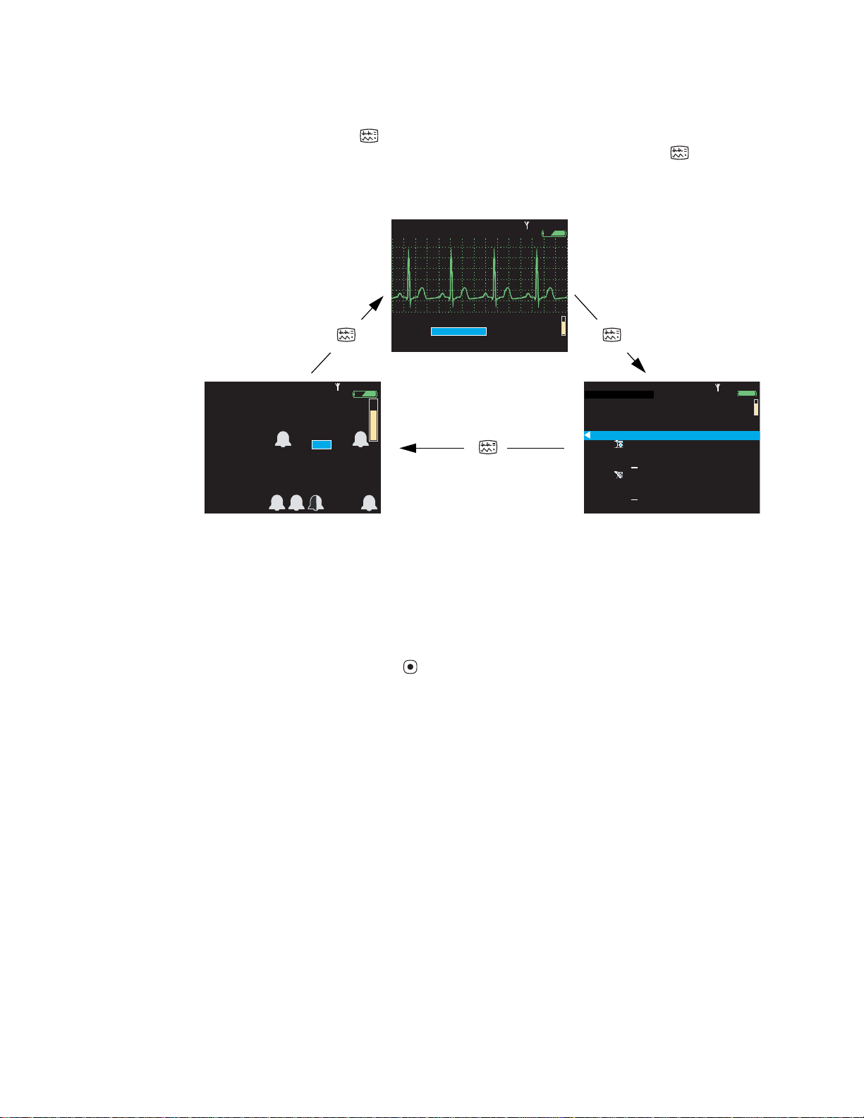
The monitor can be configured to cycle quickly through three of the five available display
formats when you press . For example, if the configuration specifies three formats—
Large Numerics, Single Waveform, and Tabular Trends—you can press repeatedly
to cycle through those formats.
Figure 14. Cycling through the configured display formats
HALL, ROBERT E.
II 1mV/cm
Adult
3456187
Rm 239
3:00:06P
80
HR/min
140/78
NIBP mmHg (102)
@2:47P Manual
12
Resp/min
97
SpO2
Single waveform
HALL, ROBERT E.
80
HR/min
NIBP mmHg (102) Manual
2:47P
3456187
Adult
Rm 239
97
SpO2
78
Large numerics
3:00:06P
12
Resp/min
HALL, ROBERT E.
Tabular
Time
12:41
12:40
12:39
12:38
12:38
12:37
12:36
12:35
12:34
12:33
12:32
12:31
8080140/78
HR/min
125
122
100
75
50
25
100
50
25
100
3456187
Adult
Rm 239
NIBP mmHg
130/65 (93)
n/a
112/87 (87)
n/a
n/a
192/110 (130)
n/a
152/78 (115)
n/a
152/78 (115)
n/a
152/78 (115)
Tabular trends
12
Resp/min
Off
22
18
16
17
19
19
19
17
19
19
19
12:41:32
SEARCH
SpO2
100
n/a
100
n/a
98
99
98
99
98
98
98
98
Certain properties of each display type can also be configured. See “Display Format” on
page 129.
To view a tabular display if no tabular trends format is specified
1. Access the Setup menu. (See “To access the setup menus” on page 37.)
2. Highlight Trends and press .
Note
All valid display configurations include at least one waveform format.
Timing out the display and the back light
To conserve battery run life, the monitor display and the back light can be configured to
turn off if no operator activity (that is, a button press) is detected for a specified number of
minutes.
• When the display is off, no patient data is visible.
• When the back light is off, patient data is visible only under direct light.
If the display and the back light are turned off due to a time out, they turn on again
immediately when an alarm or alert occurs or, if the buttons lock-out is not
enabled, when you press any monitor button.
Note
The monitor configuration determines whether the time-out feature is enabled or
disabled, and defines the default time-out period if it is enabled. If the feature is enabled in
the configuration, you can temporarily change the time-out period or disable the time out
through the Setup -> Timings menu.
Page 25

Directions for Use Overview of monitor operation 21
Locking out the display, back light, and buttons
If lock-outs are enabled, you can lock out one or more of the following elements:
Buttons To prevent unauthorized use
Back Light To extend the battery run life
Display To prevent unauthorized viewing of patient information
The monitor configuration defines which of these, if any, can be locked out. For
information on enabling or disabling lock-outs for these elements, see “Monitor
configuration” on page 103.
To lock out the configured elements
Hold down , , and simultaneously for 5 seconds.
To unlock the configured elements
Hold down , , and simultaneously for 5 seconds.
Note
Alarms and alerts immediately unlock any locked elements.
Large color display interface
Using the Large Color Display Interface (‘interface box’) optional accessory, you can
display patient vital signs from the monitor on a full-size screen. It receives video signals
from the cradle via a VGA cable.
WARNING All signal input and output (I/O) connectors are intended for
connection of only devices complying with IEC 60601-1, or other IEC standards
(for example, IEC 60950), as applicable to the monitor. Connecting additional
devices to the monitor may increase chassis or patient leakage currents. To
maintain operator and patient safety, consider the requirements of IEC 60601-1-1.
Measure the leakage currents to confirm that no electric shock hazard exists.
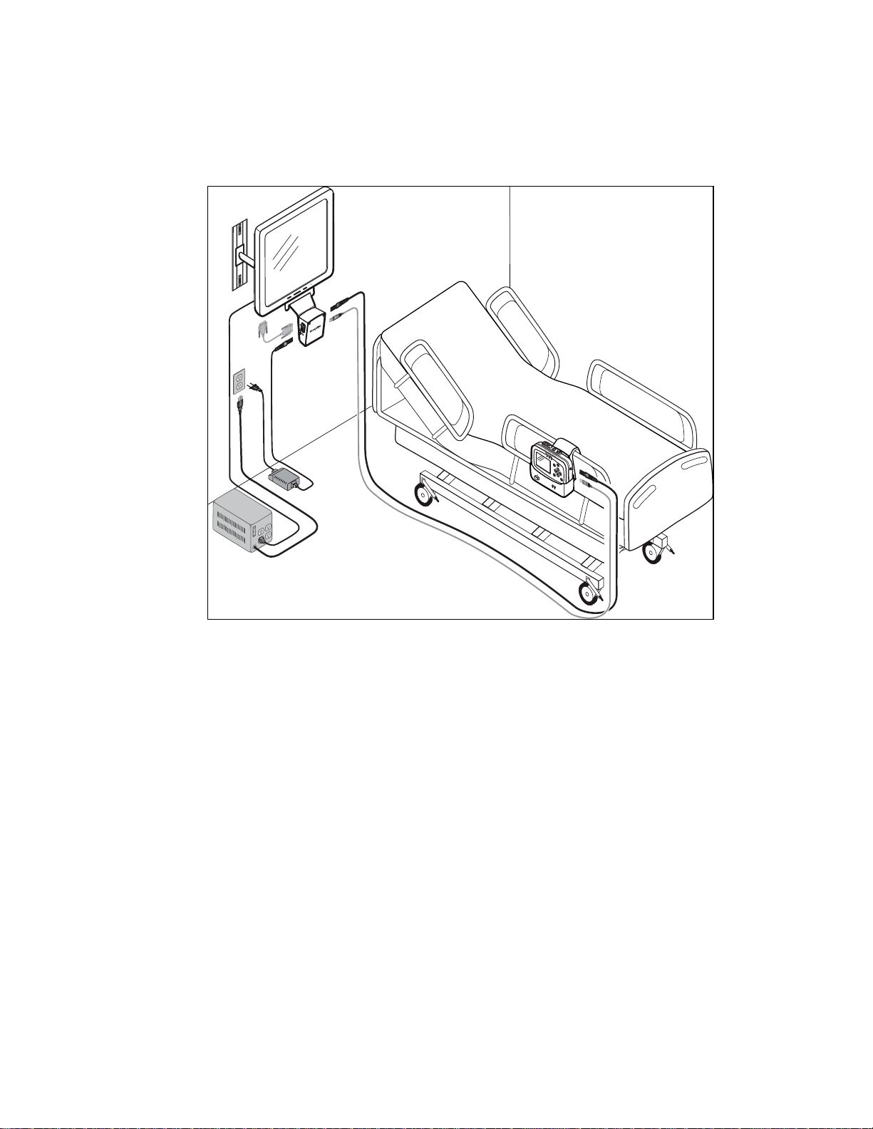
Large color display configuration options
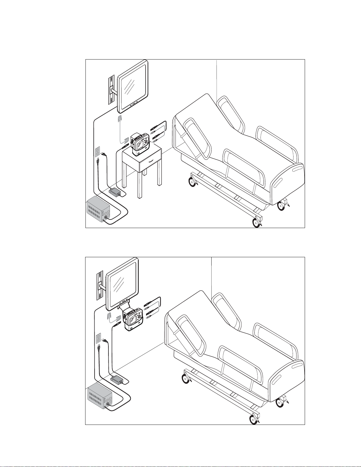
• If the interface box is mounted on the large screen (Figure 15), the screen must be
within about 3 meters of the cradle.
• If the interface box is mounted on the cradle (Figure 16), the distance between the
box and the screen is limited by the length of the VGA cable.
• If the interface box, the cradle, and the large screen are mounted together (Figure 17),
the distance from them to the patient’s bed is limited by the length of the SpO
sensor cable, the ECG cable, and the NIBP air hose (whichever is shortest).
2
Note
Caution If you require medical-grade protection against leakage current, install
an approved power conditioner between the large color display power cable and
the mains power.
The various configurations are not interchangeable. Each requires a unique
combination of screws, USB and power cables, and VGA cable.
Page 26
22 Overview of monitor operation Welch Allyn Propaq LT Vital Signs Monitor
Note
If the interface box is attached to the cradle, the bed rail hook cannot be used.
Figure 15. Interface box mounted on the large screen
Interface box mounted on
the large screen
Power conditioner
Page 27
Directions for Use Overview of monitor operation 23
Figure 16. Interface box mounted on the cradle
Interface box mounted
on the cradle
Power conditioner
Figure 17. Interface box and cradle mounted on the large screen
Interface box and cradle
mounted on the large screen
Power conditioner
Page 28
24 Overview of monitor operation Welch Allyn Propaq LT Vital Signs Monitor
15
%
60
78
98
120
S
D
M
220
75
110
35
120
50
Manual
120
50
100
90
120
50
(89)
STEWART, AN N
HR/min
NIBP/PSNI-mmHg
Resp/min
SpO2
II
SpO2
Resp
7762940
V
I
Resp
V
II
III
aVR
aVL
aVF
SpO2
15
%
60
78
98
120
S
D
M
220
75
110
35
120
50
Manual
120
50
100
90
120
50
(89)
HR/min
NIBP/PSNI-mmHg
Resp/min
SpO2
STEWART, AN N
7762940
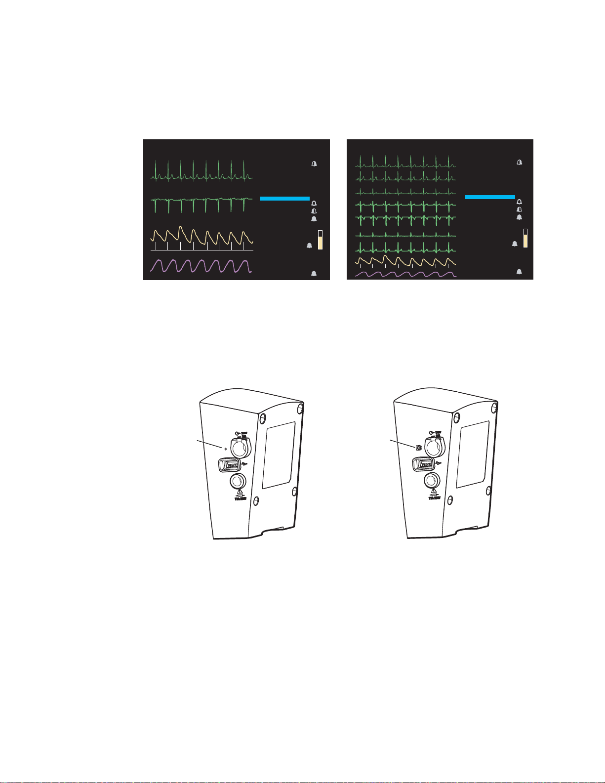
Large display viewing options
The large display shows vital signs numerics and either four or nine waveforms.
Figure 18. Large color display viewing options
STEWART, ANN
II
SpO2
Resp
7762940
HR/min
60
NIBP/PSNI-mmHg
120
78
SpO2
98
Resp/min
15
Manual
(89)
100
90
STEWART, ANN
120
50
220
75
110
35
120
50
120
50
II
III
aVR
aVL
aVF
SpO2
Resp
7762940
HR/min
60
NIBP/PSNI-mmHg
120
78
SpO2
98
Resp/min
15
Manual
(89)
100
90
120
220
110
120
120
To change between 4-waveform and 9-waveform views, insert a wire into the small hole
in the interface box near the USB connector, or press the button.
If you change the display format at least 15 seconds before shutting off power to the
interface box, the newly selected display becomes the default display when the interface
box is next powered on.
Figure 19. Switching between the 4-waveform and 9-waveform views
50
75
35
50
50
Waveformview
selector
Waveformview
selector
Determining what appears on the large display when using a 3-lead ECG cable
Figure 20. 4-waveform view, 3-lead cable
Page 29
Directions for Use Overview of monitor operation 25
Leads I, II, and III are viewable. The waveform for the lead selected at the monitor is
displayed on the large color display. Lead V cannot be displayed.
Note
When using a 5-lead cable with all electrodes attached, only leads II and V are
available in the 4-waveform view.
Figure 21. 9-waveform view, 3-lead cable
Leads I, II, and III are viewable. The waveform for the lead selected at the monitor is
displayed on the large color display. Leads V, aVR, aVL, and aVF cannot be displayed.
Note
When using a 5-lead cable with all electrodes attached, leads I, II, III, V, aVR, aVL,
and aVF are available in the 9-waveform view.
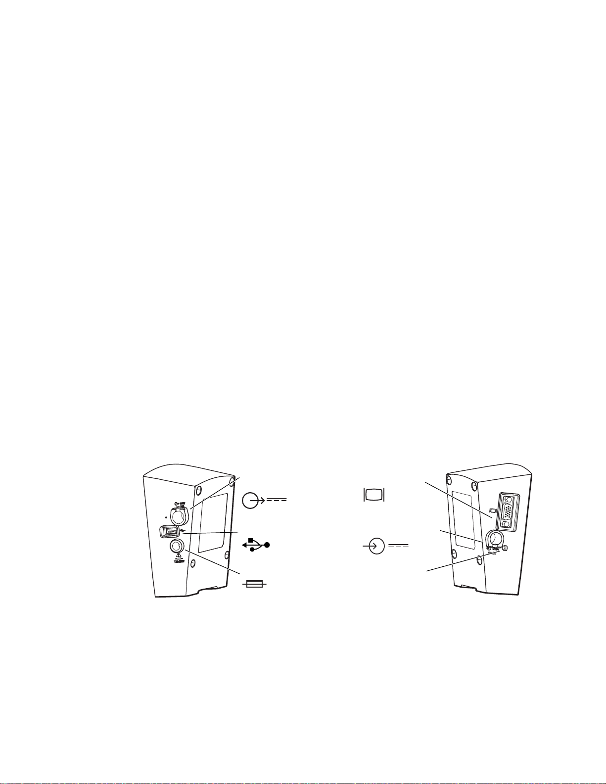
Installing the interface box
The Large Color Display Interface receives DC power from the AC power adapter and
vital-signs data from the cradle. It provides DC power to the cradle and the video signal to
the large display.
Figure 22. Interface box connections
DC power out
(to cradle)
USB in
(from cradle)
Fuse
VGA out to
(large color display)
DC power in
(from AC power adapter)
DC power indicator
When the interface box is attached to the cradle, the default power and USB cables
connect the interface box and the cradle. (See Figure 17 on page 23.)
If the interface box and the cradle are not attached, longer cables are used.
The AC power adapter is shipped with the cradle.
Note
The AC power adapter used with the Propaq CS monitor or the Propaq Encore
monitor will not power the interface box.
Page 30

26 Overview of monitor operation Welch Allyn Propaq LT Vital Signs Monitor
When the interface box is not used, the AC power adapter is attached to the cradle. When
the interface box is used, the AC power adapter is connected to it and not to the cradle.
Page 31

Directions for Use Overview of monitor operation 27
Detaching the bed rail hook from the cradle
If you are attaching the interface box to the cradle and if the cradle and the bed rail hook
are attached, you must first detach the bed rail hook from the cradle.
1. Remove the screws from the back of the bed rail hook.
2. Lift the bed rail hook off of the shoulder screws on the back of the cradle.
3. Remove the shoulder screws from the back of the cradle.
Figure 23. Detaching the bed rail hook from the cradle
2
1
3
Page 32

28 Overview of monitor operation Welch Allyn Propaq LT Vital Signs Monitor
Assembling the large color display
Refer to Figure 24, Figure 25 on page 29, or Figure 26 on page 30.
Figure 24. Mounting the interface box (with face plate) on the large display mounting bracket
60-mm screws
620-0431-00
40-mm screws
620-0432-00
Power conditioner
Long cables between box and
cradle:
008-0946-00 (USB)
008-0948-00 (Power)
Page 33

Directions for Use Overview of monitor operation 29
Figure 25. Mounting the interface box on the cradle
40-mm screws
620-0432-00
18-mm screws
620-0433-00
Power conditioner
Short cables between box
and cradle:
008-0947-00 (USB)
008-0949-00 (AC Power)
Page 34

30 Overview of monitor operation Welch Allyn Propaq LT Vital Signs Monitor
Figure 26. Mounting the interface box and the cradle on the large display mounting bracket
60-mm screws
620-0431-00
40-mm screws
620-0432-00
Power conditioner
Short cables between box
and cradle:
008-0947-00 (USB)
008-0949-00 (AC Power)
Page 35

Directions for Use Overview of monitor operation 31
About navigation
You navigate the monitor screens using , , and (arrow buttons), (action button),
and (display button).
Using the arrow buttons
Use , , and to do the following:
• Highlight an item on the display. (See “Using the highlights” on page 31.)
• Select options from a control menu.
• Use and to select options from a pop-up menu.
• Use and to change the values of numeric parameters.
Using the action button
Use to do the following:
• Display the control menu for a blue-highlighted item.
• Return from a control menu to the primary display.
• Access the Setup menu when Setup is highlighted.
• Display tabular and graphical trends when Trends is highlighted.
• Display snapshots when Snapshot is highlighted.
• Turn on the display or the back light if either has been turned off by a time-out.
• Display a pop-up menu.
Using the display button
Use to do the following:
• Cycle through the configured display formats.
• Return from a control menu to the primary display.
• Close a pop-up menu.
Using the highlights
Every screen contains a single element—the current context—highlighted by a blue field.
Some screens also contain elements—parameter values—highlighted by a green field.
About blue highlights
A blue highlight identifies the current context. For example, Figure 27 illustrates a
highlighted row in a trends display and a highlighted setting in the Waveform Size menu.
Page 36

32 Overview of monitor operation Welch Allyn Propaq LT Vital Signs Monitor
II 1mV/cm
%
12:41
12:40
12:39
12:38
12:37
12:38
12:36
125
122
100
75
50
25
130/65 (93)
112/87 (87)
192/110 (130)
n/a
n/a
n/a
n/a
22
18
16
17
19
19
98
98
99
99
98
100
n/a
12
SpO2
SEARCH
Tabular
Time
140/78
HR/min
NIBP mmHg
Resp/min
n/a
HALL, ROBERT E.
3456187
12:41:32
Adult
Rm 239
Waveform Size
0.2 mV/cm
0.5 mV/cm
1 mV/cm
2 mV/cm
4 mV/cm
8 mV/cm
140/78
80
12
97
%
HALL, ROBERT E.
3456187
3:00:06P
Adult
Rm 239
HR/min
NIBP mmHg (102)
@2:47P Manual
Resp/min
SpO2
SpO22x2x
II 1mV/cm
Figure 27. Examples of highlighted elements
HALL, ROBERT E.
II 1mV/cm
Tabular
Time
12:41
12:40
12:39
12:38
12:38
12:37
12:36
8080140/78
HR/min
125
122
100
75
50
25
3456187
Adult
NIBP mmHg
130/65 (93)
n/a
112/87 (87)
n/a
n/a
192/110 (130)
n/a
Rm 239
12
Resp/min
n/a
22
18
16
17
19
19
12:41:32
SEARCH
SpO2
100
n/a
Drop-down menu
Highlights
98
99
98
99
98
Vital-signs display
Waveform Size
0.2 mV/cm
0.5 mV/cm
1 mV/cm
2 mV/cm
4 mV/cm
8 mV/cm
In a display screen (see “About display formats” on page 19), pressing causes the
monitor to replace the current screen with another screen related to the current context.
For example, if SpO2 is highlighted in the Two waveforms display and you press ...
Figure 28. Using the action button ( )
HALL, ROBERT E.
II 1mV/cm
SpO2
140/78
80
HR/min
NIBP mmHg (102)
@2:47P Manual
Adult
3456187
Rm 239
12
Resp/min
3:00:06P
97
SpO2
(Two waveforms display)
With SpO2highlighted, press
...the monitor presents the SpO
About green highlights
Green highlights identify the current values of parameters within a given context. For
example, in the control menu shown in Figure 29, the current settings of the SpO
parameters are highlighted in green.
control menu (Figure 29).
2
2
Page 37

Directions for Use Overview of monitor operation 33
%
HALL, ROBERT E.
3456187
3:00:06P
Adult
Rm 239
II 1mV/cm
Exit
Trends
Snapshots
Setup
SpO2 Monitoring
Upper Alarm
Upper Limit
Lower Alarm
Lower Limit
HP/PR Tone
SpO2
Off
Off
Off
Off
On
On
On
Low
Med
High
100
90
Standby
80
HR/min
140/78
NIBP mmHg (102)
Resp/min
SpO2
12
97
Menus
Using control menus
Figure 29. SpO2control menu (example)
HALL, ROBERT E.
II 1mV/cm
80
HR/min
SpO2
Exit
140/78
NIBP mmHg (102)
SpO2 Monitoring
Upper Alarm
Upper Limit
Lower Alarm
Lower Limit
HP/PR Tone
Trends
3456187
Adult
Resp/min
Off
Off
Off
Off
Snapshots
Rm 239
12
On
On
100
On
90
Low
3:00:06P
97
SpO2
Standby
Med
Setup
Control context
Parameters
Current settings
Control menu
High
A control menu includes a topic name for the current context (for example, SpO2); a
column of parameters with one highlighted (for example, SpO2 Monitoring); and a
column of options, with one item in each set of options highlighted (for example, On, On,
100, On, 90, Low).
• The blue highlight indicates the parameter currently enabled for modification.
• The green highlights indicate the current settings for all parameters in the menu.
At the bottom of the screen for all control menus are links to Exit, Trends, Snapshots,
and Setup.
Example: Using a control menu
Exit Return to the vital-signs display.
Trends View a tabular history.
Snapshots View a series of 21-second waveform snapshots of the current patient’s
vital signs.
Setup Access the setup menu. (See “To access the setup menus” on page 37.)
Using the example (Figure 29), you would do the following to raise the SpO2lower alarm
limit to 95 (Step 1) and shut off the HR/PR tone (Step 2):
1. With SpO2 Monitoring highlighted, scroll (using ) to highlight Lower Limit, and
Note
press as many times as needed to raise this alarm limit to 95.
If you decrease an upper alarm limit to a value almost as low as the lower limit,
the lower limit decreases so that it is always lower than the upper limit.
If you increase a lower alarm limit to a value almost as high as the upper limit, the
upper limit increases so that it is always higher than the lower limit.
Page 38

34 Overview of monitor operation Welch Allyn Propaq LT Vital Signs Monitor
2. Scroll (using ) to HR/PR Tone, and press either or as many times as needed to
highlight Off.
Note
When you change a setting (for example, by turning off an alarm limit or by
increasing or decreasing an alarm limit), the change takes effect immediately.
3. Press or to exit the control screen and return to the vital-signs display.
Note
When you exit a control menu, the values displayed at the time you exit are the
values in effect for the monitor. If you change a parameter setting and then decide
before exiting the control menu to keep the previous setting values, you must
return the parameters to the original values before you exit the control menu.
About the HR/PR control menu
Parameter Options Parameter Options
Upper Alarm Off On Lower Alarm Off On
Upper Limits Lower Limits
About the SpO
Adult
Pediatric
Neonate
HR/PR Tone Off Low Med High Selected Source ECG SpO
control menu
2
27 - 300 beats/minute
27 - 300 beats/minute
27 - 300 beats/minute
Adult
Pediatric
Neonate
25 - 298 beats/minute
25 - 298 beats/minute
25 - 298 beats/minute
2
Parameter Options Parameter Options
Monitoring Off On Standby HR/PR Tone Off Low Med High
SpO
2
Upper Alarm Off On Lower Alarm Off On
Upper Limit Lower Limit
Adult
Pediatric
Neonate
52% - 100%
52% - 100%
52% - 100%
Adult
Pediatric
Neonate
50% - 98%
50% - 98%
50% - 98%
Page 39

Directions for Use Overview of monitor operation 35
II 1mV/cm
10
15
30
60
Exit
Trends
Snapshots
Setup
Auto
Manual
Turbo
HR/min
NIBP mmHg
Resp/min
SpO2
Off
Off
On
On
220
Lower Sys Limit
NIBP Mode
Auto Interval (min)
Upper Sys Alarm
Upper Sys Limit
Lower Sys Alarm
NIBP Manometer
Systolic
Diastolic
Mean
75
%
STEWART, ANN
7762940
3:00:06P
Adult
Rm 263
(102)
80
140/78
12
97
About the NIBP control menu
The NIBP control has submenus Manometer, Systolic, Diastolic, and Mean. Press or
to select one.
Figure 30. NIBP control menu
STEWART, ANN
II 1mV/cm
80
HR/min
NIBP Manometer
Upper Sys Alarm
Upper Sys Limit
Lower Sys Alarm
Lower Sys Limit
NIBP Mode
Auto Interval (min)
Exit
NIBP mmHg
Trends
140/78
Adult
(102)
Systolic
Off
220
Off
Manual
1 1 2 2 3 3 5 5 10
Snapshots
7762940
Resp/min
Diastolic
On
On
75
Rm 263
12
Auto
3:00:06P
97
SpO2
Mean
Turbo
15
30
Setup
%
60
Parameter Options Parameter Options
Systolic Systolic
Upper Sys Alarm Off On Lower Sys Alarm Off On
Upper Sys Limit Lower Sys Limit
Adult
Pediatric
Neonate
32 - 260 mmHg
32 - 160 mmHg
27 - 120 mmHg
Adult
Pediatric
Neonate
30 - 258 mmHg
30 - 158 mmHg
25 - 118 mmHg
NIBP Mode Auto Manual Turbo Auto Interval (min) 1 2 3 5 10 15 30 60
Diastolic Diastolic
Upper Dia Alarm Off On Lower Dia Alarm Off On
Upper Dia Limit Lower Dia Limit
Adult
Pediatric
Neonate
22 - 235 mmHg
17 - 130 mmHg
12 - 105 mmHg
Adult
Pediatric
Neonate
20 - 233 mmHg
15 - 128 mmHg
10 - 103 mmHg
NIBP Mode Auto Manual Turbo Auto Interval (min) 1 2 3 5 10 15 30 60
MAP MAP
Upper MAP Alarm Off On Lower MAP Alarm Off On
Upper MAP Limit Lower MAP Limit
Adult
Pediatric
Neonate
22 - 255 mmHg
17 - 140 mmHg
12 - 110 mmHg
Adult
Pediatric
Neonate
20 - 253 mmHg
15 - 138 mmHg
10 - 108 mmHg
NIBP Mode Manual Auto Turbo Auto Interval (min) 1 2 3 5 10 15 30 60
Page 40

36 Overview of monitor operation Welch Allyn Propaq LT Vital Signs Monitor
About the Resp control menu
Parameter Options Parameter Options
Resp Monitoring Off On Lower Alarm Off On
Upper Alarm Off On Lower Limit
Upper Limit Adult 2 - 148
Adult 4 - 150 Pediatric 2 - 148
Pediatric 4 - 150 Neonate 3 - 148
Neonate 5 - 150 Resp Lead Ld1 (RA-LA) Ld2 (RA
-LL)
Using setup menus
Use the Setup menus—Alarms, ECG, NIBP, SpO2, and Timings—to define settings for
monitor behavior.
Setting Options
Alarms
Suspend Audible Alarms Off, On (with a time value)
Alarm Tone Low, Med, High
ECG
Resp Monitoring Off, On
ECG Bandwidth Monitor, Extended
Power Source Filter 60 Hz, 50 Hz, Off
Pacer Indicator Off, On
NIBP
NIBP Format SD, SD(m), sd(M)
NIBP Units mmHg, kPa
Smartcuf Off, On
(Masimo only)
SpO
2
Sensitivity Normal, Maximum, APOD
FastSAT
Averaging Time 2, 4, 8, 10, 12, 14, 16
Timings
Back Light Time Out (Min) 2, 5, 10, 15, 30, On, Off
Off, On
Display Time Out (Min) 2, 5, 10, 15, 30, On
Demo Mode Disabled, Low, High
Page 41

Directions for Use Overview of monitor operation 37
II 1mV/cm
Exit
Trends
Snapshots
Setup
Low
Med
80
HR/min
NIBP mmHg
Resp/min
SpO2
OffOnOn
Alarm Tone
Suspend Audible Alarms
Setup
(90 sec)
12
97
%
ID: 01018VDO9PBH
3:00:06P
Adult
Rm 239
Alarms
ECG
NIBP
Timings
High
Service
Configuration
Use the Setup -> Configuration menu to change the monitor configuration without using
the Configuration Utility.
Option Note
Configuration
Select ( ) to save current settings. Replace the power-up defaults with the current
parameter settings.
Select ( ) to use factory settings. Replace the power-up defaults with the factory
settings.
Select ( ) to use file: [file name] Replace the power-up defaults with the last
downloaded configuration settings.
To access the setup menus
From any main display screen (such as Large Numerics, Dual Waveform...):
1. Highlight , HR/PR, SpO2, NIBP, Resp,or .
2. Press .
3. Highlight Setup (at the bottom of the screen) and press .
Figure 31. Setup menus
ID: 01018VDO9PBH
II 1mV/cm
80
HR/min
Setup
Suspend Audible Alarms
Alarm T one
Alarms
Service
NIBP mmHg
ECG
NIBP
Adult
Resp/min
Timings
Off
Low
Rm 239
12
Med
3:00:06P
97
SpO2
Configuration
(90 sec)
High
Setup
%
Note
Exit
Trends
Snapshots
Setup
If you change parameter settings and then change the patient mode (from adult to
pediatric, for example):
• All parameters are reset to the configuration default values for the new
patient mode.
• All stored patient data is lost.
WARNING The Setup menus are also used to access the Service menu. Do not
enter the Service menu unless you are a qualified service person.
Page 42

38 Overview of monitor operation Welch Allyn Propaq LT Vital Signs Monitor
Welch Allyn Propaq 802LTRN
Serial# F82C0DD5 V1.00.00
Portland Westside
Emergency Department
PtldWstsdED10Jun05.mnt
Ann Jones, MD
503-530-0101 x9999
Patient Mode
Wireless Communications
Start New Patient
Info
Demo
Adult
Snapshots
none saved
Enabled
Welch Allyn Propaq 802LT0N
Serial# AB72383-1 V1.00.00
Portland Westside
Emergency Department
PtldWstsdED10Jun05.mnt
Ann Jones, MD
503-530-0101 x9999
Patient Mode
Wireless Communications
Start New Patient
Info
Demo
Adult
Snapshots
14 of 20 saved
Disabled
Continue Patient
About monitor information screens
Both the start-up information screen and the monitoring information screen provide
information about the monitor.
To view the start-up information screen
From the power-on screen (Figure 7 on page 13), highlight Info.
Figure 32. Start-Up Information
Welch Allyn Propaq 802LTRN
Serial# F82C0DD5 V1.00.00
Portland Westside
Emergency Department
PtldWstsdED10Jun05.mnt
Ann Jones, MD
503-530-0101 x9999
Patient Mode
Wireless Communications
Start New Patient
Adult
Snapshots
Enabled
Info
none saved
Demo
Portland Westside
Emergency Department
PtldWstsdED10Jun05.mnt
Ann Jones, MD
503-530-0101 x9999
Patient Mode
Wireless Communications
Start New Patient
Welch Allyn Propaq 802LT0N
Serial# AB72383-1 V1.00.00
Adult
Snapshots
Disabled
Continue Patient
14 of 20 saved
Info
The start-up information screen provides the following:
• Monitor type (LTRN=wireless, LT0N=standalone), serial #, and software version #
(V X.XX.XX)
• Medical facility name and department
• Configuration file name
• Contact person’s name and telephone number
• Current patient mode (Adult, Pediatric, Neonate)
• Number of data snapshots saved (0 - 20)
• Network communications status (Enabled, Disabled)
Demo
To exit the start-up information screen, do one of the following:
• Highlight Continue Patient or Start New Patient to start monitoring.
• Highlight Demo to enter Demo mode.
• Press to turn off the monitor.
Page 43

Directions for Use Overview of monitor operation 39
II 1mV/cm
Exit
Trends
Snapshots
Setup
80
HR/min
(100)
NIBP mmHg (148-86)
Resp/min
SpO2
503-530-0101 x9999
Emergency Department
PtldWstsdED10Jun05.mnt
Ann Jones, MD
Portland Westside
12
97
%
HALL, ROBERT E.
3456187
12:41:32
Adult
Rm 239
503-530-0101 x9999
Emergency Department
PtldWstsdED10Jun05.mnt*
Ann Jones, MD
Portland Westside
To view the monitoring information screen
Highlight (in the upper right corner of the vital-signs display) and press .
Figure 33. Monitoring information
HALL, ROBERT E.
II 1mV/cm
80
HR/min
Portland Westside
Emergency Department
PtldWstsdED10Jun05.mnt
Ann Jones, MD
503-530-0101 x9999
Exit
(100)
NIBP mmHg (148-86)
Trends
3456187
Adult
Snapshots
Rm 239
12
Resp/min
12:41:32
97
SpO2
Setup
The monitoring information screen provides the following information:
• Continuous numeric and waveform display of patient vital signs
• Medical facility name and unit
• Configuration file name
• Contact person’s name and telephone number
Note
If a monitor configuration is saved after a configuration file is downloaded, the file
name shown in the information screen is followed by an asterisk (*). This is true
even if the saved configuration is identical to the downloaded configuration.
Portland Westside
Emergency Department
PtldWstsdED10Jun05.mnt*
Ann Jones, MD
503-530-0101 x9999
For more information about changing the monitor configuration, see “Changing
the default settings” on page 69.
To exit the monitoring information screen, do one of the following:
• To return to the primary display, press , or highlight Exit and press .
• To see a tabular display of vital signs, highlight Trends and press .
• To view saved snapshots of vital signs, highlight Snapshots and press .
• To view the Setup menu, highlight Setup and press .
• To turn off the monitor, press .
Page 44

40 Overview of monitor operation Welch Allyn Propaq LT Vital Signs Monitor
Select ( ) to enter Demo Mode
No data saved.
Start New Patient
Info
Demo
(unplug patient cables)
Using demo mode
In Demo mode, the monitor displays simulated patient data for all vital signs. You can use
Demo mode to familiarize yourself with the following:
• Viewing vital-signs displays
• Modifying alarm limits and other settings
• Cycling through display formats
• Responding to alarm conditions
To start Demo mode, all of the following must be true:
• The power-on screen is displayed.
• The monitor is not in NIBP Auto mode.
• Patient data was deleted when the monitor was last shut down; that is, the
monitor contains no stored patient data.
• The SpO
To enter demo mode low
and ECG cables are not connected to the monitor.
2
1. Verify that the SpO2and ECG cables are not connected to the monitor.
2. Cycle the monitor off (deleting any saved data) and then on again.
3. When the main screen appears, highlight Demo and press .
Note
If you enter Demo mode with an SpO2or ECG cable connected, the monitor
enters Demo mode for only a second or two before shutting down and powering
up in monitor mode.
If you are in Demo mode and you connect an SpO2or ECG cable or select NIBP
auto mode, the monitor shuts down and powers up to the start-up screen.
Figure 34. Power-on screen: Demo highlighted
No data saved.
Select ( ) to enter Demo Mode
(unplug patient cables)
Start New Patient
Info
Demo
Demo mode is indicated by the message ‘SIMULATION’ in the upper left corner of
the screen. If the monitor is connected to Acuity, ‘SIMULATION’ also appears on the
Acuity display.
Page 45

Directions for Use Overview of monitor operation 41
80
97
12
ID: 01018VDO9PBH
3:00:06P
Adult
Rm 239
NIBP mmHg
Resp/min
HR/min
SpO2
%
SIMULATION
S D M
II 1mV/cm
Exit
Trends
Snapshots
Setup
Low
Med
80
HR/min
NIBP mmHg
Resp/min
SpO2
OffOnOn
Alarm Tone
Suspend Audible Alarms
Setup
(90 sec)
12
97
%
ID: 01018VDO9PBH
3:00:06P
Adult
Rm 239
Alarms
ECG
NIBP
Timings
High
Service
Configuration
Figure 35. Demo mode: initial display
ID: 01018VDO9PBH
SIMULATION
80
HR/min
NIBP mmHg
When you enter Demo mode, the monitor is in ‘Demo mode low’. In this mode, the
simulated vital signs of the patient are steady and do not cause any alarms at the default
alarm limit settings. You can explore the monitor displays and menus, and you can change
the same settings and values in Demo mode that you can change in normal mode.
In Demo mode low, if you adjust the alarm limits to put the simulated patient’s vital signs
out of limits, the monitor simulates an alarm condition. Another way to simulate an alarm
condition is to switch the monitor to Demo mode high, which uses higher numeric values.
To switch to demo mode high
1. Access the Setup menu. (“To access the setup menus” on page 37.)
Adult
97
Rm 239
SpO2
3:00:06P
12
Resp/min
2. Press to highlight Timings.
Figure 36. Setup: timings
ID: 01018VDO9PBH
II 1mV/cm
80
HR/min
Setup
Suspend Audible Alarms
Alarm T one
Exit
Alarms
Service
NIBP mmHg
ECG
Trends
Adult
NIBP
Rm 239
12
Resp/min
Timings
Off
Low
Med
Snapshots
3:00:06P
97
SpO2
Configuration
(90 sec)
High
Setup
%
Timings
Default demo mode (Low)
Page 46

42 Overview of monitor operation Welch Allyn Propaq LT Vital Signs Monitor
Off
II 1mV/cm
Exit
Trends
Snapshots
Setup
80
HR/min
NIBP mmHg
Resp/min
SpO2
Demo Mode
Backlight Timeout (min)
Setup
12
97
%
ID: 01018VDO9PBH
3:00:06P
Adult
Rm 239
Alarms
ECG
NIBP
Timings
Service
Display Timeout (min) 2
Low
5
Off2 5
SIMULATION
High
Configuration
80
97
12
ID: 01018VDO9PBH
3:00:06P
Adult
Rm 239
NIBP mmHg
Resp/min
HR/min
SpO2
%
SIMULATION
S D M
The Timings menu specifies the Demo mode—Demo mode low, which simulates
normal vital signs, and Demo mode high, which simulates a higher heart rate (HR),
higher respiration rate (Resp), and lower oxygen saturation (SpO2).
3. Press to highlight Demo mode, and press or to highlight High.
Figure 37. Setup: timings: demo mode high
ID: 01018VDO9PBH
SIMULATION
II 1mV/cm
80
HR/min
Setup
Backlight Timeout (min)
Display Timeout (min)
Demo Mode
Exit
4. Press or to return to the main display.
Figure 38. Demo mode high: initial display
ID: 01018VDO9PBH
SIMULATION
Alarms
Service
NIBP mmHg
ECG
Trends
80
HR/min
Adult
NIBP
Snapshots
Adult
Rm 239
12
Resp/min
Timings
101015153030OnOnOff
101015153030OnOnOff
Low
High
Rm 239
97
SpO2
3:00:06P
97
%
SpO2
Configuration
Setup
3:00:06P
Demo Mode: High
The monitor generates an alarm within seconds of reading this new set of simulated
vital signs. The red alarm indicator (Figure 39) illuminates and flashes, the numerics
for all violating vital signs—HR, SpO
moves to the most recent alarming numeric.
NIBP mmHg
12
Resp/min
, and Resp—turn red and flash, and the highlight
2
Page 47

Directions for Use Overview of monitor operation 43
14040/7878
80
12
97
%
HALL, ROBERT E.
3456187
3:00:06P
Adult,
Rm 239
HR/min
NIBP mmHg (102)
@2:47P Manual
Resp/min
SpO2
SpO22x2x
II 1mV/cm
125
88
31
ID: 01018VDO9PBH
3:00:06P
Adult
Rm 239
NIBP mmHg
Resp/min
HR/min
SpO2
%
Select ( ) for controls
S D M
Select ( ) to delete patient data
You have pressed the Power Off button.
Delete & Shut Down
Cancel
Setup
and shut down.
ID: 01018VDO9PBH
15:01:24
Adult
Rm 239
SIMULATION
Figure 39. Demo mode high: simulated alarm condition
Flashing red: patient alarm
HR limit violation (red)
SpO
ID: 01018VDO9PBH
HALL, ROBERT E.
Select ( ) for controls
II 1mV/cm
Adult
Adult,
3456187
Rm 239
Rm 239
3:00:06P
3:00:06P
limit violation (red)
2
125
HR/min
SpO2
80
HR/min
NIBP mmHg (102)
NIBP mmHg
@2:47P Manual
88
SpO2
31
12
Resp/min
97
SpO2
Resp/min
Resp limit violation (red)
With the monitor simulating an alarm, you can practice responding to alarms. (See
“Responding to an alarm” on page 85.)
To exit demo mode
Press . The Demo Mode Power Off screen appears.
Figure 40. Demo mode power off
ID: 01018VDO9PBH
SIMULATION
You have pressed the Power Off button.
Select ( ) to delete patient data
Delete & Shut Down
Adult
and shut down.
Cancel
Rm 239
15:01:24
Setup
• To shut down the monitor, press . (No data can be saved from Demo mode.)
• To resume Demo mode, highlight Cancel and press .
• To access the Setup menu, highlight Setup and press .
Page 48

44 Overview of monitor operation Welch Allyn Propaq LT Vital Signs Monitor
Select ( ) to delete patient data
You have pressed the Power Off button.
Delete & Shut Down
Cancel
Setup
and shut down.
15:01:24
Adult
Rm 239
There is patient data stored for
Hall, Robert E. ID: 3456187
Save & Shut Down
HALL, ROBERT E.
3456187
Power saving
To maximize battery life, the monitor display shuts off when the following conditions are
all true:
• No button press for a period of n seconds. (n is configurable.) See “Timing out the
display and the back light” on page 20.
• No active alarms or alerts
• No Acuity Message window
• No Patient ID entry window
Turning off the monitor
To turn off the monitor
Press .
The Power-off screen appears:
Figure 41. Power-off screen
Cancel
15:01:24
Setup
HALL, ROBERT E.
You have pressed the Power Off button.
There is patient data stored for
Hall, Robert E. ID: 3456187
Select ( ) to delete patient data
and shut down.
Delete & Shut Down
3456187
Adult
Save & Shut Down
Rm 239
Highlight the desired action and press .
Note
If you press to power down before leaving the power-on screen (Figure 7 on
page 13), the monitor shuts down without presenting the screen shown above.
Communicating with an Acuity Central Station
See “Monitoring in communication with Acuity” on page 73, and see Acuity Directions
for use.
About error detection
The monitor can detect conditions that prevent it from operating properly. If this occurs, it
displays an error message and an error number. Follow the directions displayed on the
screen.
Page 49

Directions for Use Overview of monitor operation 45
Transporting the monitor with the patient
An ambulatory patient can wear or carry the monitor using the wearable strap or the
patient carry strap (optional accessories). Medical personnel can use the transport
stretcher carry strap to keep the monitor with a patient during stretcher transport.
WARNING When the patient is wearing or carrying the monitor, carefully route
any patient cabling to reduce the possibility of patient entanglement or
strangulation. Use the supplied garment clips to secure the cable properly.
WARNING When positioning straps on the patient, make sure the straps do not
entangle the patient’s neck or cause choking.
WARNING Make sure the straps do not restrict the movement of the patient’s
limbs or create a hazard for the patient when the patient is walking or moving.
WARNING Never use a strap to carry or pick up both the monitor and the cradle.
The straps are not intended to support, and cannot support, the combined weight
of the monitor and the cradle.
To attach the wearable strap
WARNING Do not put the wearable strap on the patient while the patient is in
bed. The intended use of the wearable strap is to keep the monitor—without the
cradle—with the patient when the patient is ambulatory.
Figure 42. Wearable strap
1. Place the wearable strap on the sitting or standing patient and adjust all components
for a comfortable, secure fit (Figure 42 left).
2. Connect the wearable strap securely to the monitor strap mounts (Figure 42 right).
3. Carefully arrange the strap and the monitor on the patient to avoid bruising or other
skin injuries.
Page 50

46 Overview of monitor operation Welch Allyn Propaq LT Vital Signs Monitor
To use the patient carry strap
WARNING Do not use the patient carry strap to lift or carry both the monitor and
the cradle. The patient carry strap is not intended to support (and cannot support)
the weight of both the monitor and the cradle. Attempting to carry both the
monitor and the cradle with a patient carry strap could lead to patient injury and to
damage to the monitor and the cradle.
1. Remove the monitor from the cradle.
2. Detach the monitor cables from any accessories.
3. Verify that all cables are disentangled from the bed and any bedside tables.
4. Connect the ends of the carry strap to the strap mounts on the monitor.
Note
Be sure that each end of the carry strap snaps into place.
Figure 43. Patient carry strap
To use the transport stretcher carry strap
1. With the monitor facing away from the stretcher and the patient, attach one end of
the strap to a monitor strap mount.
2. Run the monitor strap under the stretcher restraint straps, near the patient’s waist.
3. Attach the other end of the strap to the other strap mount.
Figure 44. Monitor secured to the patient during stretcher transport
4. Before transporting the patient, verify that all monitor cables are clear.
Page 51

47
3
Standalone monitoring
Overview
The monitor is available in standalone models (802LT0N and 802LT0S) and in wireless
models (802LTAN, 802LTAS, 802LTRN and 802LTRS).
This chapter describes the operation of the standalone monitor and of the wireless
monitor when it is not in communication with the Welch Allyn Flexnet®network and an
Acuity®Central Station.
About the Model 802LT0N and 802LT0S (standalone) monitors
The model 802LT0N and 802LT0S monitors operate in standalone mode. They measure
and display vital signs, store patient data, and locally indicate alarms and alert conditions.
• The configuration of the monitor is not affected by Acuity.
• The vital signs stored by the monitor are not sent to Acuity.
• Alarms and alerts generated by the monitor do not appear on Acuity.
• Alarms and alerts generated by Acuity do not appear on the monitor.
• Acuity does not update the monitor time and date settings.
About the Model 802LTAN, 802LTAS, 802LTRN and 802LTRS (wireless)
monitors
See “Monitoring in communication with Acuity” on page 73.
Preparing for a new patient
To begin monitoring a new patient
1. If the monitor is on, press to turn it off.
If prompted to save or delete existing data, highlight Delete and press . The monitor
deletes any saved data and temporary settings, and then shuts down.
2. Press to turn on the monitor.
• If the monitor holds stored data from the previously monitored patient, it displays
the “data saved” start-up screen:
Page 52

48 Standalone monitoring Welch Allyn Propaq LT Vital Signs Monitor
Select ( ) to delete data
and start a new patient.
Portland Westside Hospital
Emergency Department
Note!
There is patient data stored for
Hall, Robert E. ID: 3456187
Start New Patient
Continue Patient
Info
Demo
Select ( ) to Start a New Patient.
No data saved.
Start New Patient
Info
Demo
Portland Westside Hospital
Emergency Department
ID: 0101819RO17Q
8:82:56
AdultRmRm
NIBP mmHg
Resp/min
HR/min
SpO2
%
S D M
Figure 45. Start-up with saved data
Portland Westside Hospital
Emergency Department
Note!
There is patient data stored for
Hall, Robert E. ID: 3456187
Select ( ) to delete data
Start New Patient
and start a new patient.
Continue Patient
Info
Demo
• If the data from the previously monitored patient was deleted on shut-down, the
“no data saved” start-up screen appears:
Figure 46. Start-up with no saved data
Portland Westside Hospital
Emergency Department
No data saved.
Select ( ) to Start a New Patient.
Start New Patient
Info
Demo
3. Highlight Start New Patient and press . The first configured data display appears.
In place of a patient name, ID: is followed by a string that is generated by the monitor
when you select ‘Start New Patient’. This AutoID string, unique to each new patient,
identifies the patient until you supply appropriate patient identification data.
Note
To bypass patient ID entry, press .
Figure 47. Data display with AutoID
ID: 0101819RO17Q
HR/min
Adult
SpO2
8:82:56
Start-up AutoID
NIBP mmHg
4. In the primary data display, highlight ID: (upper left) and press .
The Patient Information Entry screen appears:
Resp/min
Page 53

Directions for Use Standalone monitoring 49
Last
Middle
First
ID#
Rm#
A B C D E F G H I J K L M N O P Q R S T U V
W X Y Z 1 2 3 4 5 6 7 8 9 0 -
Select ( ) to enter highlighted character
Confirm
Cancel
Backspace
Last
Middle
First
ID#
Rm#
A B C D E F G H I J K L M N O P Q R S T U V
W X Y Z 1 2 3 4 5 6 7 8 9 0 -
Select ( ) to enter highlighted character
Confirm
Cancel
HALL ERORO
Backspace
3456187
Figure 48. Patient information entry
Last
Middle
First
Select ( ) to enter highlighted character
Confirm
ID#
Backspace
Cancel
Rm#
Entry fields
Character field
5. Enter the ID and name of the new patient.
a. Press or to highlight (blue) a character in the character field (Figure 49).
b. Press to copy it to the green-highlighted location in the entry fields (Figure 48).
c. Repeat from step a until all characters are entered into the field.
d. Press until the insertion point in the entry field changes from green to blue.
e. Press or to move the insertion point to another entry field.
f. Press to return to the character field.
g. Repeat from step a until all fields are complete.
Note
To correct an error in an entry field: Place the cursor (step d and step e)tothe
right of the error location, highlight and enter Backspace in the character field to
delete the erroneous character, and then enter the correct character.
Figure 49. Patient information entry (continued)
Last
Middle
HALL
Select ( ) to enter highlighted character
Confirm
First
ID#
3456187
Backspace
Cancel
Rm#
Next letter highlighted
6. Highlight Confirm and press .
\
Note
Name alone is not sufficient to confirm a patient ID; thus, you can confirm the
patient name only after you have entered the patient ID.
7. Verify that the patient mode (adult, pediatric, or neonate) is set correctly for this
patient.
Neonatal Term birth through 28 days, or up to 44 gestational weeks.
Pediatric Between 29 days and 12 years.
Adult 13 years and older.
If the current patient mode setting is not correct:
a. Highlight the current patient mode (Adult, Pediatric,orNeonate) and press .
b. From the Patient Mode selection menu, highlight the appropriate patient mode
and press .
Page 54

50 Standalone monitoring Welch Allyn Propaq LT Vital Signs Monitor
Patient Mode
Adult
Pediatric
Neonate
Patient Mode
Adult
Pediatric
Neonate
HALL, ROBERT E.
3456187
3:00:06P
Adult
Rm 239
NIBP mmHg
Resp/min
HR/min
SpO2
%
S D M
Note! You are changing the
patient mode from Adult to Pediatric.
This will change settings to default
Pediatric values and delete previous
If this is correct, highlight “Confirm”
then press Select ( ).
Cancel
Confirm
patient data.
II 1mV/cm
Year
Date Format
HR/min
NIBP mmHg
Resp/min
SpO2
%
14:49:37
Adult
Time Format
Hour
Minute
Month
Day
HALL, ROBERT E.
3456187
Rm 239
12 Hour
24 Hour
14
45
3
17
2005
mm/dd/yy
dd.mm.yy
yy/mm/dd
Set
Cancel
Figure 50. Changing patient mode
Patient Mode
Adult
Pediatric
Neonate
Patient Mode
Adult
Pediatric
Neonate
c. A confirmation screen appears:
Figure 51. Confirming a change of patient mode
HALL, ROBERT E.
Note! You are changing the
patient mode from Adult to Pediatric.
This will change settings to default
Pediatric values and delete previous
HR/min
patient data.
If this is correct, highlight “Confirm”
then press Select ( ).
Cancel
NIBP mmHg
Adult
3456187
Rm 239
SpO2
Confirm
3:00:06P
Resp/min
d. To confirm the change, highlight Confirm and press .
Note
When you change the patient mode and confirm the change:
• All vital-signs data for the patient is lost.
• All monitor settings revert to the defaults for the new patient mode.
8. Verify that the displayed time and date are correct.
• The monitor displays time in the 12-hour (AM/PM) or 24-hour format, and displays
the date in the mm/dd/yy, dd.mm.yy, or yy/mm/dd format.
• The date does not appear on the primary display screens. It appears on the
snapshot list and on the snapshot display.
a. Highlight the time display (in the upper right corner of the screen) and press .
The Time/Date screen appears.
Figure 52. Time/date screen: 24-hour format
Rm 239
Cancel
14:49:37
SpO2
yy/mm/dd
HALL, ROBERT E.
II 1mV/cm
HR/min
Time Format
Hour
Minute
Month
Day
Year
Date Format
NIBP mmHg
Set
12 Hour
14
45
17
2005
mm/dd/yy
Adult
3456187
Resp/min
24 Hour
dd.mm.yy
b. If the displayed time or date is not correct, press or to move the highlight
from one parameter to another, and press or to change the value of the
highlighted parameter. For example, to change the time display format from
24-hour to 12-hour, highlight Time Format and press either or once.
24-hour format
Page 55

Directions for Use Standalone monitoring 51
II 1mV/cm
Year
Date Format
HR/min
NIBP mmHg
Resp/min
SpO2
%
14:49:54
Adult
Time Format
Hour
Minute
Month
Day
HALL, ROBERT E.
3456187
Rm 239
12 Hour
24 Hour
2P
45
3
17
2005
mm/dd/yy
dd.mm.yy
yy/mm/dd
Set
Cancel
Select ( ) to delete data
and start a new patient.
Portland Westside Hospital
Emergency Department
Note!
There is patient data stored for
Hall, Robert E. ID: 3456187
Start New Patient
Continue Patient
Info
Demo
Figure 53. Time/date screen: 12-hour format
HALL, ROBERT E.
II 1mV/cm
HR/min
Time Format
Hour
Minute
Month
Day
Year
Date Format
NIBP mmHg
Set
12 Hour
2P
45
17
2005
mm/dd/yy
Adult
3456187
Resp/min
24 Hour
dd.mm.yy
Rm 239
Cancel
14:49:54
SpO2
12-hour format
yy/mm/dd
c. When the time and date are correct and formatted appropriately, press to
accept the changes and return to the vital-signs display.
Note
If you change the time or date settings and then decide not to accept the
changes, press to cancel the changes and return to the vital-signs display.
Continuing to monitor a patient on power-up
If patient data was saved when the monitor was last turned off (see “To turn off the
monitor” on page 44), you can resume monitoring that patient when the monitor is turned
on again. (When patient data is saved, the monitor settings are also saved.)
To resume monitoring the same patient:
1. Turn on the monitor. The “patient data stored” screen appears:
Figure 54. Start-up with saved data
Portland Westside Hospital
Emergency Department
Note!
There is patient data stored for
Hall, Robert E. ID: 3456187
Select ( ) to delete data
Start New Patient
and start a new patient.
Continue Patient
Info
Demo
2. Verify that the displayed name and ID match that of the current patient.
3. Highlight Continue Patient and press .
Page 56

52 Standalone monitoring Welch Allyn Propaq LT Vital Signs Monitor
Select ( ) to continue
monitoring this patient.
Portland Westside Hospital
Emergency Department
Note!
There is patient data stored for
Hall, Robert E. ID: 3456187
Start New Patient
Continue Patient
Info
Demo
Figure 55. Start-up with saved data
Portland Westside Hospital
Emergency Department
Note!
There is patient data stored for
Hall, Robert E. ID: 3456187
Select ( ) to continue
Start New Patient
monitoring this patient.
Continue Patient
Info
Demo
Monitoring ECG and Resp
Overview
Note
In this manual, lead refers to an ECG electrode or lead wire, and Lead refers to a
waveform source.
You can monitor heart signs (ECG) and respiration rate (Resp) using either a 3-lead or a
5-lead ECG cable. Using a 3-lead cable, you can display one signal waveform for Lead I, II,
or III. Using a 5-lead cable, you can display either one or two signal waveforms (I, II, III, V;
and if enabled in the configuration, aVR,aVL,oraVF). You can also display the SpO2or
Resp waveform in place of an ECG waveform.
WARNING Always monitor and set alarms for SpO2when using impedance
pneumography to monitor respiratory function.
WARNING When monitoring respiration via impedance pneumography, always
select the ECG Lead with the most prominent QRS complex. The monitor rejects
cardiovascular artifact, but this function depends upon accurate ECG R-wave
detection.
WARNING Do not place the monitor near another respiration monitor. Resp
measurement frequencies can cause mutual interference.
WARNING Do not perform impedance pneumography on paced patients.
Pacemaker pulses can sometimes be falsely counted as breaths.
WARNING Always keep patient motion to a minimum. Motion artifact can cause
incorrect readings of breath rate or heart rate.
WARNING If a disconnected lead is too close to other electrical devices, it can
cause a false heart rate, a false respiration rate, or a failure to display a “Lead Fail”
message.
WARNING The monitor displays + + + for HR numerics between 301-350 beats
per minute. For heart rates above 350 beats per minute, it might display
incorrectly low heart readings, due to intermittent picking of R-waves.
WARNING The monitor does not provide internal arrhythmia analysis; therefore,
arrhythmias can cause the monitor to display inaccurate heart rates.
WARNING Make sure the patient mode is correct. Incorrect patient mode can
result in inaccurate heart rate readings and inappropriate alarm settings.
Page 57

Directions for Use Standalone monitoring 53
WARNING (1) During a surgical procedure, do not use small ECG electrodes.
(2) Select ECG electrode attachment points remote from the surgical site and
remote from the electrosurgical return electrode. (3) Use electrosurgical return
electrodes with the largest practical contact area. (4) Assure proper application of
the electrosurgical return electrode to the patient.
High-intensity radio-frequency (RF) energy from external sources, such as an
improperly connected electrosurgical unit, can induce heat into electrodes
and cables, which can cause burns on the patient and can lead to
measurement errors.
WARNING Always use the provided garment clips to route ECG cables away
from the patient’s head.
WARNING Use only accessories approved by Welch Allyn. The use of any other
accessories can result in inaccurate patient data, can damage the equipment, and
can void your product warranty. Refer to the accessory list or
www.welchallyn.com.
WARNING Always use accessories according to the standards of your facility
and according to the manufacturer's directions.
Note
WARNING Never use ECG cables with loose or faulty detachable lead wires.
These can cause erratic behavior of the ECG and respiration waveforms due to
intermittent ECG lead wire connections.
WARNING Resp is derived from the same leads as the ECG channel, so the
monitor determines which signals are cardiovascular artifact and which signals are
a result of respiratory effort. If the breath rate is within five per cent of the heart
rate or is a multiple or submultiple of the heart rate, the monitor might ignore
breaths and trigger a respiration alarm.
Caution Never use an ECG cable longer than 10 feet (3 meters) including
extensions. If you use an ECG extension cable with an ECG cable longer than
4 feet, the monitor acts as though no ECG cable is connected.
Caution To protect the monitor from damage during defibrillation or
electrosurgery, for accurate ECG information, and for protection against noise
and other interference, use only ECG electrodes and cables specified or supplied
by Welch Allyn (these cables have the required current-limiting resistors). Follow
recommended application procedures.
The monitor contains type CF fully isolated patient-connected circuitry, but it is
not intended for direct application on a patient’s heart.
Severe artifact and interference (such as defibrillation interference) can cause the
waveform to move off of the display for a few seconds before it is restored.
Impedance pneumography (Resp) is not recommended for use with
high-frequency ventilation.
The monitor counts as breaths any respiratory efforts larger than twice the
background cardiovascular artifact.
Note
Use only silver/silver chloride electrodes. Other electrodes, such as stainless
steel electrodes, squeeze-bulb electrodes, or electrodes with dissimilar metals,
are subject to large offset potentials due to polarization. Other electrodes can also
have slower recovery time after the application of defibrillator pulses.
Page 58

54 Standalone monitoring Welch Allyn Propaq LT Vital Signs Monitor
Monitoring ECG
1. Inspect the ECG cable. Replace it if it shows any signs of wear, breakage, or fraying.
2. Plug the cable into the monitor.
3. Select electrode sites on the patient, choosing flat areas and avoiding fatty or bony
areas and major muscles.
Figure 56. ECG leads - actual placement
RA
V1
5-lead, adult and pediatric
RA
3-lead, adult and pediatric
RL
LL
LL
LA
V6
Six possible V lead electrode
placement sites for the C lead.
RA
LA
4. Shave or clip the hair from the electrode sites.
LA
LL
3-lead, neonatal
5. Thoroughly clean the skin, using soap and water, isopropyl alcohol, or skin preparation
pads, and lightly rub it dry.
Caution To protect the patient from allergic reactions to electrodes, refer to the
electrode manufacturer’s directions for use.
6. If you are using gelled electrodes, verify that the electrode expiration date has not
passed and that the gel is intact and not dried out.
If you are not using gelled electrodes, apply a mound of gel (1/4-inch to 1/2-inch, or
0.6-cm to 1.3-cm) to each electrode contact area.
7. Attach lead wires to the electrodes before applying them to the patient.
8. Apply the electrodes to the patient in the proper locations (Figure 56).
Note
At least three appropriate electrode connections are required for ECG/Resp
monitoring.
Page 59

Directions for Use Standalone monitoring 55
140/78
80
12
97
%
HALL, ROBERT E.
3456187
3:00:06P
Adult
Rm 239
HR/min
NIBP mmHg (102)
@2:47P Manual
Resp/min
SpO2
SpO22x2x
II 1mV/cm
Figure 57. ECG leads - placement displays, 5-lead and 3-lead
The locations of the circles displayed on the monitor (Figure 57) for each lead are
fixed, and do not indicate the exact placement of the electrodes on the patient.
If the monitor detects that some lead wires are not connected, it displays an “ECG
Fault” equipment alert and a chest diagram indicating the location of the
disconnected lead or leads. If the disconnected lead(s) invalidate the Lead used for
HR determination, then the monitor reassigns, if possible, the Lead used for HR. If
the reassignment succeeds, the monitor then displays another equipment alert with
the message “ECG Lead changed”.
Figure 58. ECG leads - disconnected leads
Disconnected leads
X
X
X
9. When all leads are properly connected, confirm that the monitor displays the ECG
waveform, heart rate, and other patient data.
Figure 59. All vital signs displayed
HALL, ROBERT E.
II 1mV/cm
SpO2
Adult
3456187
Rm 239
3:00:06P
HR/min
To change the waveform selection
NIBP mmHg (102)
@2:47P Manual
140/78
80
12
Resp/min
97
SpO2
1. Highlight the current waveform source selection (Lead II, for example) and press .
Page 60

56 Standalone monitoring Welch Allyn Propaq LT Vital Signs Monitor
%
STEWART, ANN
7762940
15:14:28
Adult
Rm 263
HR/min
NIBP mmHg
Resp/min
SpO2
II 1mV/cm
80
12
97
Waveform Source
Lead I
Lead II 6 sec
Lead III
aVR
aVL
aVF
V
Resp
SpO2
Add 2nd Wave
%
STEWART, ANN
7762940
7:05P
Adult
Rm 263
HR/min
Resp/min
SpO2
Resp 4x
60
20
97
130/74
NIBP mmHg (88)
@7:05P Manual
Waveform Source
Lead I
Lead II
Lead III
aVR
aVL
aVF
V
Resp 24 sec
SpO2
Add 2nd Wave
%
HR/min
NIBP mmHg
Resp/min
SpO2
II 1mV/cm
I 4mV/cm
STEWART, ANN
7762940
12:41:32
Adult
Rm 263
80
12
97
Waveform Size
0.2 mV/cm
0.5 mV/cm
1 mV/cm
2 mV/cm
4 mV/cm
8 mV/cm
Figure 60. Waveform source: II
STEWART, ANN
II 1mV/cm
Waveform Source
Lead I
Lead II 6 sec
Lead III
aVR
aVL
aVF
V
Resp
SpO2
80
Add 2nd Wave
HR/min
NIBP mmHg
7762940
Adult
12
Resp/min
Rm 263
15:14:28
97
%
SpO2
2. Highlight your waveform source choice and press or .
Figure 61. Waveform source: Resp
STEWART, ANN
Resp 4x
Waveform Source
Lead I
Lead II
Lead III
aVR
aVL
aVF
V
Resp 24 sec
SpO2
60
Add 2nd Wave
HR/min
NIBP mmHg (88)
@7:05P Manual
130/74
7762940
Adult
20
Resp/min
Rm 263
7:05P
97
%
SpO2
Note
If you scroll to the bottom selection of the Waveform Source menu—either Add
2nd Wave or Remove 2nd wave—the selection takes effect immediately and the
monitor returns to the primary data display.
Note
In the Waveform Source menu, either the source Lead or the waveform period
can be highlighted. If the waveform period is highlighted, a second trace of the
same source will be cascaded to double the period obtained from a single trace.
To change the waveform size
1. Highlight the current waveform scale (1mV/cm, for example) and press .
Figure 62. Waveform size popup menu
STEWART, ANN
II 1mV/cm
Waveform Size
0.2 mV/cm
0.5 mV/cm
1 mV/cm
I 4mV/cm
2 mV/cm
4 mV/cm
8 mV/cm
80
HR/min
NIBP mmHg
Adult
7762940
Rm 263
12
97
Resp/min
12:41:32
%
SpO2
2. Highlight the desired scaling factor and press . (Waveform size does not affect
QRS-detector sensitivity.)
Page 61

Directions for Use Standalone monitoring 57
II 1mV/cm
Exit
Trends
Snapshots
Setup
60Hz
50Hz
80
HR/min
140/78
NIBP mmHg (102)
Resp/min
SpO2
OffOnOn
Power source filter
Resp Monitoring
Setup
12
97
%
HALL, ROBERT E.
3456187
3:00:06P
Adult
Rm 239
Alarms
ECG
NIBP
Timings
Off
Configuration
ECG Bandwidth
Pacer indicator
Monitor
OffOnOn
Extended
Service
About pacemakers and ECG monitoring
If the patient being monitored has a pacemaker, the monitor detects and can indicate the
occurrence of pacemaker signals. If the Pacer Indicator setting is ON, the monitor displays
and prints vertical dashed lines to indicate detected pacemaker signals. If Pacer Indicator
is OFF, the monitor continues to detect the pacemaker signals but does not display or
print the pacer markers.
WARNING Signals differ between pacemakers. The Association for
Advancement of Medical Instrumentation (AAMI) cautions that “in some devices,
rate meters may continue to count the pacemaker rate during occurrences of
cardiac arrest or some arrhythmias. Do not rely entirely upon rate meter alarms.
All pacemaker patients should be kept under close or constant observation.”
WARNING Use of respiration monitoring by impedance pneumography can
affect the operation of some pacemakers. If pacemaker operation is affected, turn
off respiration pneumography. (See Figure 63 on page 57.)
WARNING Always use fresh ECG electrodes and make sure the ECG cable lead
wires make good connections. The presence of pacer-like noise can cause the
displayed heart rate to be erratic even though the ECG trace might look
undistorted with the pacer indicator off.
To enable or disable the display of pacer indicators
1. Access the Setup menu. (See “To access the setup menus” on page 37.)
2. Highlight ECG.
Figure 63. Turning the pacer indicator off in the ECG setup menu
HALL, ROBERT E.
II 1mV/cm
80
HR/min
Setup
Resp Monitoring
ECG Bandwidth
Power source filter
Pacer indicator
Exit
Alarms
Service
140/78
NIBP mmHg (102)
ECG
Trends
Adult
NIBP
3456187
Rm 239
12
Resp/min
Timings
Off
Monitor
60Hz
50Hz
Off
Snapshots
3:00:06P
97
SpO2
Configuration
Extended
Off
Setup
%
Pacer indicator Off
3. Highlight Pacer indicator and press or to highlight Off or On.
4. To exit the Setup menu, press or , or highlight Exit and press .
Note
If the pacemaker signal is strong enough, the monitor displays it as a waveform
spike. This is true with Pacer indicator ON or OFF.
In accordance with the Pacer Pulse Rejection specification (“Pacer pulse
rejection” on page 145.), pacemaker pulses are not counted as heartbeats
whether Pacer Indicator is On or Off.
Noise on the ECG signal might be detected as pacer signals, causing the pacer
indicator to appear on the display. If you do not need to indicate pacemaker
signals, turn off the pacemaker indicator for a better ECG waveform display.
Page 62

58 Standalone monitoring Welch Allyn Propaq LT Vital Signs Monitor
II 1mV/cm
Exit
Trends
Snapshots
Setup
60Hz
50Hz
80
HR/min
140/78
NIBP mmHg (102)
Resp/min
SpO2
OffOnOn
Power source filter
Resp Monitoring
Setup
12
97
%
HALL, ROBERT E.
3456187
3:00:06P
Adult
Rm 239
Alarms
ECG
NIBP
Timings
Off
Configuration
ECG Bandwidth
Pacer indicator
Monitor
OffOnOn
Extended
Service
Improving the waveform display
If the power source filter is off, noise from the power source can cause an unclear or
noisy waveform.
To change the power source filter to reduce noise
1. Access the Setup menu. (See “To access the setup menus” on page 37.)
2. Highlight ECG.
Verify that the setting for Power source filter is correct for the power source in your
facility. If you do not know what this setting should be, consult a qualified service
person.
3. Highlight Power source filter and press or as needed to select 60 Hz, 50 Hz,
or Off.
Figure 64. Turning on the 60-Hz power source filter in the ECG setup menu
HALL, ROBERT E.
II 1mV/cm
80
HR/min
Setup
Resp Monitoring
ECG Bandwidth
Power source filter
Pacer indicator
Exit
Alarms
Service
NIBP mmHg (102)
Trends
4. Exit the Setup menu by pressing or .
Monitoring respiration
Resp is based on impedance pneumography, where respirations are sensed from the
ECG electrodes.
Note
Note
All ECG cables listed for the Propaq LT monitor in the accessory list or at
www.welchallyn.com permit respiration monitoring and electrosurgical
interference suppression.
To measure Resp with Lead II selected, the LL lead must be attached to the
patient.
140/78
ECG
Adult
NIBP
3456187
Rm 239
12
Resp/min
Timings
Off
Monitor
60Hz
50Hz
Off
Snapshots
3:00:06P
97
SpO2
Configuration
Extended
Off
Setup
%
Power source filter 60 Hz
Resp is part of ECG monitoring. The Resp numeric is displayed (in purple) in the lower
right corner. To view the Resp waveform:
Change the waveform source to Resp. (See “To change the waveform selection” on
page 55.)
WARNING Use of respiration monitoring by impedance pneumography can
affect the operation of some pacemakers. If pacemaker operation is affected, turn
off respiration pneumography. (See Figure 63 on page 57.)
Page 63

Directions for Use Standalone monitoring 59
%
HALL, ROBERT E.
3456187
3:08:16
Adult
Rm 239
HR/min
Resp/min
SpO2
Resp 2x2x
80
12
97
NIBP mmHg
%
HALL, ROBERT E.
3456187
3:08:16
Adult
Rm 239
HR/min
Resp/min
SpO2
Resp 8x8x
80
12
97
NIBP mmHg
Figure 65. Resp waveform, default size (2x)
HALL, ROBERT E.
Resp
80
HR/min
For more detail, change the waveform size to 8x. (See “To change the waveform size”
on page 56.)
Note
Figure 66. Resp waveform enlarged for detail (8x)
Waveform size does not affect breath-detector sensitivity.
HALL, ROBERT E.
Resp
NIBP mmHg
Adult
Adult
3456187
Rm 239
12
Resp/min
3456187
Rm 239
3:08:16
97
SpO2
3:08:16
80
HR/min
NIBP mmHg
12
97
Resp/min
SpO2
Page 64

60 Standalone monitoring Welch Allyn Propaq LT Vital Signs Monitor
Monitoring SpO
The monitor can be purchased with the Nellcor or the Masimo SpO2option. Most of this
chapter pertains to either configuration. Monitors with the Masimo technology, however,
can provide additional SpO2data. (“About the Masimo SpO2display” on page 64.)
WARNING Accurate measurements of oxygen saturation, when derived from
pulse oximetry, depend to a great extent on patient condition and proper sensor
placement. Patient conditions such as shivering and smoke inhalation can result in
erroneous readings. If you believe a measurement might be inaccurate, verify it
using another clinically accepted measurement method, such as arterial blood gas
measurements using a co-oximeter.
WARNING Use only SpO2accessories listed in the accessory list or at
www.welchallyn.com. Inspect sensors and cables, and discard any that are
damaged. Do not use a sensor with exposed optical components.
WARNING Use of Masimo LNOP sensors/cables will not provide protection in
accordance with IEC defibrillation standards when used with this device.
WARNING If you need to increase the length of the sensor cable, use only one
extension. Use of multiple extensions can adversely affect performance. Do not
attach any cable that is intended for computer use to the SpO2connector at the
monitor.
WARNING Tissue damage and erroneous measurements can be caused by
incorrect application or use of a sensor. (Examples of bad practices: wrapping the
sensor too tightly, applying supplemental tape, failing to periodically inspect the
sensor site, leaving a sensor on too long in one place.) Refer to the
manufacturer’s directions for specific instructions on application and use, and for
description, warnings, cautions, and specifications.
2
WARNING Do not modify the sensor.
WARNING Do not wet the sensor or immerse it in fluid. Do not attempt to
sterilize a sensor.
WARNING Sensors exposed to ambient light while not applied to a patient can
exhibit seminormal saturation readings. Be sure the sensor is securely placed on
the patient and check its application often to ensure accurate readings.
WARNING Inaccurate measurements might be caused by venous pulsations.
WARNING The pulse oximeter can be used during defibrillation, but the
readings might be inaccurate for a short time.
WARNING Do not use the pulse oximeter as an apnea monitor.
WARNING During SpO2monitoring, a very sudden and substantial change in
pulse rate can result in erroneous pulse rate readings. Always validate the patient
data and patient condition before effecting an intervention or a change in patient
care.
Page 65

Directions for Use Standalone monitoring 61
WARNING Interfering substances: Carboxyhemoglobin can erroneously
increase readings; the level of increase is approximately equal to the amount of
carboxyhemoglobin present. Methemoglobin and other dysfunctional
hemoglobins can also cause erroneous readings. Further assessment beyond
pulse oximetry is recommended. Intravascular dyes, or any substances
containing dyes, that change usual arterial pigmentation can cause erroneous
readings. Darkly pigmented skin can adversely affect SpO2readings.
WARNING For a premature infant, high oxygen levels might predispose the
infant to develop retinopathy. Therefore, the upper alarm limit for oxygen
saturation must be carefully selected in accord with accepted clinical standards
and considering the accuracy range of the monitor.
Caution If liquid gets into the SpO2connector cavity, discontinue SpO
2
monitoring until the liquid is removed and the cavity is dry.
1. Inspect the SpO2cable. Replace it if it shows any signs of wear, breakage, or fraying.
2. Plug the cable into the sensor and the monitor.
Each SpO2sensor is intended for application to a specific site and site size on the
patient. To obtain optimal performance, use the right sensor and apply it as instructed
by the sensor manufacturer.
3. Clean the application site. Remove anything, such as nail polish, that could interfere
with the operation of the sensor.
4. Attach the SpO2sensor to the patient according to the manufacturer’s directions for
use, observing all warnings and cautions.
5. Confirm that the monitor displays SpO2data within a few seconds of being
connected to the patient.
Note
In some newer monitors, the pitch of the heart tone rises and falls as oxygen
saturation increases and decreases. In other monitors, the pitch of the heart tone
does not change.
• If ambient light is too bright, shield the sensor site with opaque material. Failure
to do so can result in inaccurate measurements. Light sources that can affect
performance include the following:
- surgical lights (especially those with a xenon light source)
- bilirubin lamps
- fluorescent lights
- infrared heating lamps
- direct sunlight.
• To help reduce unnecessary SpO2alarms when NIBP and SpO2are monitored
simultaneously, place the NIBP cuff and the SpO2sensor on different limbs.
• Do not attach the SpO2sensor on the same limb as an arterial catheter or
intravascular line.
• The pulse signal can disappear if any of the following conditions exists:
- the sensor is too tight
- ambient light is too bright
- an NIBP cuff is inflated on the same limb as the sensor
- arterial occlusion occurs near the sensor
Page 66

62 Standalone monitoring Welch Allyn Propaq LT Vital Signs Monitor
SpO2 Monitoring
Upper Alarm
Upper Limit
Lower Alarm
Lower Limit
HP/PR Tone
SpO2
Off
Off
Off
Off
On
On
On
Low
Med
High
100
90
Standby
- the patient is in cardiac arrest or shock
- the patient has hypotension, severe vasoconstriction, severe anemia, or
hypothermia
• If poor perfusion affects performance for an adult, consider using the adult nasal
sensor.
• If a sensor is connected and the sensor light does not come on within 3 seconds:
- Verify that SpO
is turned on (Figure 67 on page 62)
2
- Replace the sensor
• If excessive or prolonged patient movement interferes with measurements,
consider the following possible solutions:
- be sure the sensor is secure and properly applied
- use a new sensor with fresh adhesive backing
- select a different type of sensor
- move the sensor to a less active site
6. Periodically verify that the sensor remains properly positioned on the patient.
About SpO2spot check
Note
The Spot Check feature is available only if it is enabled in the monitor
configuration. Refer to “Using the Configuration Utility to configure the monitor”
on page 116.
When SpO2is turned on, the monitor generates an alarm condition whenever SpO
2
readings are interrupted, such as when the sensor is disconnected from the patient after
the monitor begins taking SpO2readings.
Using the SpO2Spot Check feature, however, you can take any number of spot SpO
2
readings at random intervals, attaching and detaching the sensor repeatedly without
generating alarms.
To prepare to take a spot check reading
1. Highlight SpO2 and press .
2. Highlight SpO2 Monitoring, press to highlight Off, and press to return to the
main screen.
Figure 67. Turning off SpO2monitoring
SpO2
SpO2 Monitoring
Upper Alarm
Upper Limit
Lower Alarm
Lower Limit
HP/PR Tone
Off
Off
Off
Off
100
On
Standby
On
On
90
Low
Med
High
Press to move the
highlight to Off.
‘SpO2’ has changed to ‘SpO2@ (time)’. Spot checks are now enabled.
Page 67

Directions for Use Standalone monitoring 63
80
HALL, ROBERT E.
3456187
3:11:24P
Adult
Rm 239
NIBP mmHg
Resp/min
HR/min
SpO2 @ 3:03P
%
S D M
SpO2
On
Off
Spot Check
HALL, ROBERT E.
3456187
3:11:30P
Adult
Rm 239
Resp/min
PR/min
SpO2 Spot Check
%
NIBP mmHg
SEARCH
S D M
Figure 68. SpO2monitoring turned off
HALL, ROBERT E.
80
HR/min
NIBP mmHg
To take an SpO
2
3456187
Adult
SpO2 @ 3:03P
Rm 239
3:11:24P
Resp/min
spot check reading
SpO2Monitoring is Off
1. Enable spot checks. (See “To prepare to take a spot check reading” on page 62.)
2. Attach the sensor to the monitor and the patient.
3. Highlight SpO2 @ XX:XX and press . The SpO
Note
The SpO2drop-down menu can be accessed only when SpO2is set to Off.
drop-down menu appears.
2
Figure 69. SpO2drop-down menu
SpO2
On
Off
Spot Check
Enable continuous automatic SpO2function
Disable automatic SpO2function (enable Spot Checks)
Take a Spot Check reading
4. Press to highlight Spot Check.
• The drop-down menu disappears. SEARCH appears above SpO2Spot Check (with
pulse rate if SpO2is the source of pulse rate).
Figure 70. SpO2spot check: waiting for an SpO2signal
HALL, ROBERT E.
PR/min
NIBP mmHg
3456187
Adult
Rm 239
SEARCH
SpO2 Spot Check
3:11:30P
Resp/min
• After a few seconds, the SpO2heart-beat indicator starts showing heart beats.
• After about 30 seconds, SEARCH disappears and the pulse oximetry reading
appears.
SEARCH indicates that the monitor
is waiting for pulse oximetry data.
Page 68

64 Standalone monitoring Welch Allyn Propaq LT Vital Signs Monitor
78
98
HALL, ROBERT E.
3456187
3:12:13P
Adult
Rm 239
Resp/min
PR/min
SpO2 @ 3:05P
%
NIBP mmHg
S D M
Figure 71. SpO2spot check: pulse rate reading
HALL, ROBERT E.
78
PR/min
NIBP mmHg
• The spot check ends, and SpO
• The SpO2text on the display screen now includes the time of the most recent
SpO2measurement. For example: SpO2 @ 3:05P.
Note
5. Detach the sensor from the patient.
6. To take another spot check later, repeat from step 2 (above).
To return to continuous SpO2measurements
1. Highlight SpO2 @ XX:XX and press .
Spot-check readings are included in trend displays.
3456187
Adult
98
SpO2 @ 3:05P
Rm 239
3:12:13P
Resp/min
Pulse rate
monitoring is again turned off.
2
2. Press to turn automatic SpO2On. The pop-up menu disappears.
To adjust the SpO2and ECG pulse tone volume
1. Highlight SpO2 and press .
2. Highlight HR/PR Tone.
3. Highlight the desired volume level (Off, Low, Med,orHigh) and press .
About the Masimo SpO2display
The Masimo SpO2option provides the following additional features and indicators.
The monitor (models 802LTAS, 802LTRS and 802LT0S) must be configured
specifically to display the Masimo parameters.
Signal IQ (SIQ) (Signal Identification and Quality indicator) A horizontal line
below the SpO2waveform, with vertical spikes indicating
the relative reliability of the oxygen saturation readings.
(Higher spikes indicate greater reliability.)
Perfusion Index (PI) An assessment, expressed as a percentage between 0.02
and 20, of the relative pulse strength at the monitoring
site.
FastSAT The tracking of rapid changes in arterial oxygen saturation.
Sensitivity Normal, APOD, and Maximum.
Note
Page 69

Directions for Use Standalone monitoring 65
Normal For typical monitoring.
APOD For monitoring when the probe is likely to detach from the
patient because of wet skin, motion, or other unusual
circumstances.
Maximum For monitoring patients with extremely low perfusion.
Averaging Time The period (in seconds) over which multiple SpO2
measurements are taken and a result is derived.
Monitoring blood pressure (NIBP)
WARNING Always use a properly fitting cuff, placing it carefully on the patient
according to the instructions presented below. Failure to fit and locate the cuff
correctly can lead to inaccurate pressure readings.
WARNING During monitoring, periodically observe the patient’s limb to make
sure that the circulation is not impaired for a prolonged period. Prolonged
impairment of circulation or improper cuff placement can cause bruising.
WARNING Do not use the monitor to simultaneously measure NIBP on one
patient and monitor ECG on another patient.
WARNING If an NIBP measurement is suspect, repeat the measurement. If you
are still uncertain about the reading, verify it using another method.
WARNING Do not take NIBP measurements during cardiopulmonary bypass.
WARNING When monitoring NIBP, match the monitor patient mode to the NIBP
cuff. For neonates, set the monitor to Neonatal Mode unless the circumference
of the limb is too large for the cuff. In that case, use the Pediatric Mode.Be
aware, however, that the maximum cuff inflation limits are based on the patient
mode, not the cuff; the maximum cuff inflation limits for Pediatric Mode are
greater than for Neonate Mode. (See “NIBP” on page 148 for values.)
Caution Pulse-rate measurements generated through the blood pressure cuff
or through SpO2are subject to artifact and might not be as accurate as heart-rate
measurements generated through ECG or through manual palpation.
When the monitor is powered on, the default cuff inflation pressure is based on the
patient mode. (See “Default inflation pressure” on page 148.) After an NIBP
measurement occurs, the monitor adjusts the inflation pressure to optimize subsequent
NIBP measurements.
Note
Always cycle the monitor power before you begin to monitor another patient.
Normal physiological pressure variations affect NIBP measurements from reading
to reading.
If the monitor is in Adult mode and a neonate cuff is connected to the monitor,
the monitor generates an equipment alert.
If the battery charge is low and the monitor is not in the cradle, the battery icon
indicates low battery and NIBP monitoring is disabled.
Page 70

66 Standalone monitoring Welch Allyn Propaq LT Vital Signs Monitor
NIBP Mode:
II 1mV/cm
Exit
Trends
Snapshots
Setup
HR/min
NIBP mmHg
Resp/min
SpO2
NIBP
Systolic
Diastolic
Mean
%
STEWART, ANN
7762940
3:00:06P
Adult
Rm 263
Manometer
Manual
50
100
150
200
250
300
To monitor blood pressure
1. Select cuff size based on limb circumference. Use only hoses and cuffs listed in the
accessory list or at www.welchallyn.com.
2. Squeeze all the air from the cuff before placing the cuff on the patient.
3. Place the cuff on the limb, as near heart level as possible.
Figure 72. Cuff placement
Cuff applied evenly and snugly. The
center of the cuff is at heart level,
and the bottom edge is one inch (2.5
cm) above the antecubital fossa.
Possible cuff placements for neonates
• The cuff must fit snugly without being uncomfortably tight.
• The hose must be free of kinks and not pinched.
4. Align the point where the tubing connects to the cuff over the brachial or other
appropriate artery.
Note
If you are simultaneously monitoring blood pressure and SpO2, you can reduce or
eliminate unnecessary SpO2alarms by placing the cuff and the SpO2sensor on
different limbs.
5. Screw the hose connector onto the NIBP air connector on the top of the monitor (see
Figure 4 on page 9).
6. Press to start a reading.
Within a few seconds, the pump starts, the cuff begins to inflate, and the manometer
screen appears.
Figure 73. NIBP: initial view
STEWART, ANN
II 1mV/cm
HR/min
NIBP
NIBP Mode:
0 0 50
Exit
NIBP mmHg
Manometer
Manual
100
Trends
Adult
Systolic
150
7762940
Rm 263
Resp/min
Diastolic
200
Snapshots
3:00:06P
SpO2
Mean
250
Setup
%
300
7. When the cuff is fully inflated, the manometer bar dynamically displays the pressure
reading.
Page 71

Directions for Use Standalone monitoring 67
NIBP Mode:
II 1mV/cm
Exit
Trends
Snapshots
Setup
HR/min
NIBP mmHg
Resp/min
SpO2
NIBP
Systolic
Diastolic
Mean
%
STEWART, ANN
7762940
3:00:06P
Adult
Rm 263
Manometer
Manual
NIBP in progress.
145
50
100
150
200
250
300
NIBP Mode:
II 1mV/cm
Exit
Trends
Snapshots
Setup
PR/min
NIBP mmHg
Resp/min
SpO2
NIBP
Systolic
Diastolic
Mean
%
STEWART, ANN
7762940
3:00:06P
Adult
Rm 263
Manometer
Manual
50
100
150
200
250
300
(98)
79
132/83
Figure 74. NIBP: reading in progress
STEWART, ANN
NIBP in progress.
II 1mV/cm
HR/min
NIBP
NIBP Mode:
145
Exit
NIBP mmHg
Manometer
Manual
50
Trends
100
Adult
Systolic
150
7762940
Rm 263
Resp/min
Diastolic
200
Snapshots
3:00:06P
SpO2
Mean
250
Setup
%
Manometer pressure indicator bar
300
When the cycle completes, control returns to the previous direct-access display. To
view the final NIBP readings on the manometer scale, select Manometer from the
Setup NIBP menu.
Figure 75. NIBP: reading complete
STEWART, ANN
II 1mV/cm
79
PR/min
NIBP
NIBP Mode:
NIBP mmHg
Manometer
Manual
132/83
Systolic
Adult
(98)
7762940
Rm 263
Resp/min
Diastolic
3:00:06P
%
SpO2
Mean
Systolic, diastolic, and MAP
(numeric)
Systolic, diastolic, and MAP
(graphical)
2 2 50
Exit
100
Trends
150
Snapshots
200
250
300
Setup
• If you need to stop the reading and vent the cuff at any time during the
measurement, press .
• If the monitor cannot get a valid NIBP reading, it displays the message
‘NIBP retry in progress’ in the upper left corner of the screen. Then, depending on
settings and patient mode, the monitor attempts one or two more
measurements. If the retries fail to produce a valid reading, the monitor displays
an NIBP error message.
Note
For every inch the cuff is placed above the heart, add 1.9 mmHg (0.253 kPa) to the
displayed NIBP reading. For every inch below the heart, subtract 1.9 mmHg
(0.253 kPa).
8. If motion artifact such as shivering or coughing interferes with NIBP readings, do the
following:
• Position the patient’s limb away from the body so that the applied cuff is not in
contact with the patient’s body or any other object (such as a bed rail). Keep the
cuff as close to heart level as possible.
• Verify that the Smartcuf filter is ON. (See “Improving NIBP accuracy with
Smartcuf” on page 68.)
• Verify that the ECG leads are properly connected to the patient, and monitor ECG
during NIBP. (ECG monitoring is required for Smartcuf.)
Page 72

68 Standalone monitoring Welch Allyn Propaq LT Vital Signs Monitor
Note
Note
The message ???/???/(???) in an NIBP TREND display or printout indicates that
the monitor could not complete an NIBP measurement during that period.
On-demand NIBP readings (manual or turbo) are delayed by 8 seconds if they are
started while the monitor is in a power-saving mode such as display time-out.
Improving NIBP accuracy with Smartcuf
Many factors can adversely affect an NIBP measurement: cardiac arrhythmias, sudden
changes in blood pressure, patient motion such as convulsions or shivering, sudden cuff
movement, vibration, vehicle motion, or a weak pulse. The Smartcuf feature increases
NIBP measurement accuracy in the presence of moderate motion artifact or diminished
pulses.
s
Note
To enable Smartcuf
1. Simultaneously monitor ECG and NIBP.
2. Access the Setup menu. (See “To access the setup menus” on page 37.)
3. Highlight NIBP, highlight Smartcuf, and enable the Smartcuf filter.
Smartcuf can function only when ECG is being monitored.
If Smartcuf is enabled and motion artifact is so severe that it still affects measurement
accuracy, the measurement is marked with the symbol on the display. During certain
types of arrhythmias and other situations where a good ECG signal cannot be obtained,
consider disabling Smartcuf, as follows:
To disable Smartcuf
1. Access the Setup menu.
2. Highlight NIBP, highlight Smartcuf, and disable the Smartcuf filter.
Taking automatic NIBP readings
In the Auto NIBP mode, for intervals shorter than 5 minutes, the monitor immediately
begins taking NIBP readings at the specified interval. For intervals of 5 minutes or longer,
the readings begin when the time of day is a multiple of the interval. (If the interval is 15
minutes, for example, then the readings begin at 00, 15, 30, or 45 minutes after the hour.)
To start automatic NIBP readings
1. Select and apply the appropriate NIBP cuff and hose. (“Monitoring blood pressure
(NIBP)” on page 65.)
2. Highlight NIBP and press .
3. Highlight NIBP Mode and select Auto.
4. Highlight Auto Interval (min) and select an interval.
Note
After you invoke an automatic NIBP, expect a delay before the monitor starts the
first measurement. The delay can be as long as the interval selected.
Page 73

Directions for Use Standalone monitoring 69
To stop automatic NIBP readings
1. Highlight NIBP and press .
2. Highlight NIBP Mode and select Manual.
Taking NIBP readings using Turbo mode
In Turbo mode, the monitor starts an NIBP reading and then takes as many more readings
as possible within five minutes.
To use the Turbo mode
1. Select and apply the NIBP cuff and hose. (“Monitoring blood pressure (NIBP)” on
page 65.)
2. Highlight NIBP and press .
3. Highlight NIBP Mode and select Turbo.
Note
To end the Turbo mode
If you cycle the monitor power, NIBP returns to auto mode.
Press or select NIBP Mode Manual. The monitor returns to Auto NIBP
measurement mode.
NIBP measurements in power-saving mode
When a manual or turbo NIBP activity awakens the monitor from power-saving mode
(“Power saving” on page 44), cuff inflation pressure is reset to default levels and cuff
inflation is delayed for up to 8 seconds.
NIBP disabled when the battery is low
If the battery is low and the monitor is operating on battery power, NIBP functions are
disabled and the monitor displays the message “NIBP off. Low battery.”
If you attempt to start an NIBP measurement during a low-battery condition, the monitor
displays an equipment alert with the message “Low battery. NIBP disabled.”
Note
Inserting a monitor into a powered cradle during a low-battery condition
immediately enables NIBP monitoring.
Changing the default settings
You can change the default settings (the monitor configuration) using the following
methods:
• Save the current settings as the new default settings.
• Restore the last downloaded configuration.
• Restore the factory settings.
Page 74

70 Standalone monitoring Welch Allyn Propaq LT Vital Signs Monitor
II 1mV/cm
Exit
Trends
Snapshots
Setup
80
HR/min
NIBP mmHg
Resp/min
SpO2
Select ( ) to save current settings.
12
97
%
ID: 01018VDO9PBH
3:00:06P
Adult Rm 239
Select ( ) to use factory settings.
Select ( ) to use file: n/a
Setup
Alarms
ECG
NIBP
Timings
Service
Configuration
ID: 12549M6I9ERF
03:52:57
AdultRmRm
NIBP mmHg
HR/min
SpO2
%
M
Note! You are changing the
default settings to current
If this is correct, highlight
“Confirm” and then press
Cancel
Confirm
settings.
Select ( ).
ID: 12549M6I9ERF
03:53:45
AdultRmRm
NIBP mmHg
HR/min
SpO2
%
M
If this is correct, highlight
“Confirm” and then press
Cancel
Confirm
Select ( ).
Note! You are changing the
default settings to file:
post-op4 15 Dec 06
• Download another configuration from a PC. (See “Using the Configuration Utility
to configure the monitor” on page 116.)
To save the current settings as the new default settings
1. Access the Configuration Setup menu.
80
HR/min
Setup
Alarms
NIBP mmHg
ECG
NIBP
Resp/min
Timings
12
Configuration
97
SpO2
%
Service
Select ( ) to save current settings.
Select ( ) to use factory settings.
Select ( ) to use file: n/a
Exit
Trends
Snapshots
Setup
2. Highlight Select ( ) to save current settings and press .
3. In the confirmation screen, highlight Confirm and press .
ID: 12549M6I9ERF
Note! You are changing the
default settings to current
settings.
If this is correct, highlight
HR/min
“Confirm” and then press
Select ( ).
Cancel
NIBP mmHg
Adult
SpO2
Confirm
S S D D M
03:52:57
%
To restore the last downloaded configuration
1. Access the Configuration Setup menu, highlight Select ( ) to use file:
configuration_file_name, and press .
2. In the confirmation screen, highlight Confirm and press .
ID: 12549M6I9ERF
HR/min
NIBP mmHg
Adult
Note! You are changing the
default settings to file:
post-op4 15 Dec 06
If this is correct, highlight
“Confirm” and then press
Select ( ).
Cancel
S S D D M
SpO2
Confirm
03:53:45
%
To restore the factory configuration
1. Access the Configuration Setup menu, highlight Select ( ) to use factory settings,
and press .
2. In the confirmation screen, highlight Confirm and press .
Page 75

Directions for Use Standalone monitoring 71
ID: 12549M6I9ERF
03:53:45
AdultRmRm
NIBP mmHg
HR/min
SpO2
%
M
Note! You are changing the
default settings to factory
If this is correct, highlight
“Confirm” and then press
Cancel
Confirm
settings.
Select ( ).
Select ( ) to delete patient data
You have pressed the Power Off button.
Delete & Shut Down
Cancel
pSetup
and shut down.
15:01:24
Adult
Rm 239
There is patient data stored for
Hall, Robert E. ID: 3456187
Save & Shut Down
HALL, ROBERT E.
3456187
ID: 12549M6I9ERF
Note! You are changing the
default settings to factory
settings.
If this is correct, highlight
HR/min
“Confirm” and then press
Select ( ).
NIBP mmHg
Cancel
S S D D M
Adult
SpO2
Confirm
To discontinue monitoring
1. Press . The Power Off screen appears.
Figure 76. Power-off
HALL, ROBERT E.
You have pressed the Power Off button.
There is patient data stored for
Hall, Robert E. ID: 3456187
Adult
3456187
Rm 239
03:53:45
%
15:01:24
Select ( ) to delete patient data
Delete & Shut Down
and shut down.
Save & Shut Down
Cancel
Setu
• If you intend to continue monitoring the same patient when the monitor is turned
on again, and if you want to save the stored vital-signs data and monitor settings
(to print them at a PC), highlight Save & Shut Down and then press . The
monitor saves the patient data and the monitor settings, and then turns off.
• If you do not intend to continue monitoring the same patient when the monitor is
turned on again, highlight Delete & Shut Down and then press . The monitor
turns off without saving the data and the settings.
2. Disconnect the leads and sensors from the patient.
If you press and then decide that instead of turning off the monitor you want to resume
monitoring the same patient, do one of the following:
• Highlight Cancel and press .
• Wait for 30 seconds.
• Press .
Note
When you power down from Demo mode, you cannot save settings and
patient data.
Page 76

72 Standalone monitoring Welch Allyn Propaq LT Vital Signs Monitor
Page 77

Monitoring in communication
73
4
with Acuity
About wireless monitoring
The model 802LTAN, 802LTAS, 802LTRN and 802LTRS wireless monitors can operate
either in standalone mode or in communication with a Welch Allyn Acuity Central Station.
(See “Standalone monitoring” on page 47.)
While the wireless monitor is connected to the FlexNet network, patient data gathered by
the monitor is continuously stored at Acuity. At the Acuity station you can access this
patient information and perform administrative functions, including the following:
• Admit, transfer, and discharge a patient in the Acuity unit.
• Edit the patient description (name, physician, and so on).
• Review and print patient data such as trends and waveforms.
For more information about Acuity and the FlexNet wireless network, refer to Acuity
directions For use.
For Model 802LTAN and 802LTAS monitors, the radio, by default, authenticates against
the WA RADIUS server running on an Acuity Central Station. If the hospital IT department
requires a different authentication/encryption solution, then the monitor, using the factorydefault radio configuration, cannot connect to the network.
WARNING When monitoring a patient who has a pacemaker, position the
monitor to maintain a minimum distance of 6 inches (16 cm) between the monitor
and the pacemaker. If you have any reason to suspect that the monitor is
interfering with the pacemaker, immediately turn the monitor off and
provide appropriate patient care. The Health Industry Manufacturers
Association recommends this minimum distance (6 inches or 16 cm) between a
hand-held wireless radio and a pacemaker, which is consistent with the
independent research by, and recommendations of, Wireless Technology
Research.
WARNING When considering a treatment protocol that involves wireless
communication of patient data, be aware of this limitation:
When the monitor is not connected to the network by wireless connection:
Acuity does not receive patient alarms or alerts from the monitor.
Acuity does not perform arrhythmia and ST analysis on patient data and
therefore does not generate related alarms.
WARNING If you establish a USB link to any active host while the monitor is in
network communication with Acuity, the wireless connection is lost.
Page 78

74 Monitoring in communication with Acuity Welch Allyn Propaq LT Vital Signs Monitor
HALL, ROBERT E.
3456187
3:00:06P
Adult
Rm 239
Note
When the monitor is used in Canada:
To provide maximum shielding (to prevent radio interference to the licensed
service), the monitor is intended to be operated indoors and away from windows.
Radio equipment (or its transmit antenna) that is installed outdoors is subject to
licensing.
Afin de fournir un écran de blindage maximal (pour empêcher que cet appareil
cause du brouillage au service faisant l’objet d’une licence), l’appareil doit être
utilisé à l’intérieur et devrait être placé loin des fenêtres. Si le matériel (ou son
antenne d’émission) est installé à l’extérieur, il doit faire l’objet d’une licence.
Establishing communication with Acuity
If the monitor is enabled for communication with Acuity, communication is established
automatically whenever the monitor is within range of the network.The monitor always
indicates the status of the connection:
Figure 77. Connection status indicator
The monitor is not enabled for communication with Acuity.(blank)
The monitor is communicating via USB cable with a PC.
The monitor is associated with the network and is
communicating with Acuity.
(Flashing) The monitor is associated with the network but
is not communicating with Acuity.
(Continuous) The monitor is not associated with the
network and is not communicating with Acuity.
HALL, ROBERT E.
Verify that the monitor, within a minute or two, displays to indicate that the connection
to Acuity has been established.
Upon connecting to the network, the monitor uploads the following data to Acuity:
• Patient information and trends stored at the monitor before the network
connection was established
• Monitor settings
At the same time, Acuity downloads some configuration settings to the monitor. (See
“About Acuity-defined configuration” on page 104.)
For information on monitoring vital signs, see the following:
ECG/Resp “Monitoring ECG and Resp” on page 52
SpO
2
NIBP “Monitoring blood pressure (NIBP)” on page 65
“Monitoring SpO2” on page 60
Adult
3456187
Rm 239
3:00:06P
Page 79

Directions for Use Monitoring in communication with Acuity 75
Monitoring a patient outside of network range
Monitors are typically deployed in an active wireless network environment where devices
continually communicate with a central station. These monitors occasionally leave the
wireless coverage area during transport to a procedure room (for example, a trip to X-ray).
When a monitor goes outside of the network range, monitoring continues locally.
Caution Be aware that moving the monitor out of the Acuity network range
breaks the radio link, immediately stopping communication of patient
vital-signs data.
The monitor provides local Resp, NIBP, HR/PR and SpO2alarms or equipment alerts. The
following also happens:
• An alert occurs at Acuity with the message DROPOUT.
• An alert occurs at the monitor with the message Check Acuity/network connection.
• The monitor emits audible alert tones.
• The appropriate caregiver presses to acknowledge the alert.
When the monitored patient is again within range of the Acuity network, the monitor
reconnects to the network and wireless monitoring resumes.
Caution Be aware that it can take as long as three minutes to restore
communication with the Acuity network and resume the communication of
patient vital-signs data.
Note
Patient monitor behavior during operation outside of wireless network
coverage areas
When the monitor leaves a wireless coverage area, it can exhibit the following
characteristics:
• The monitor aggressively searches to locate the wireless Acuity network.
• The monitor consumes battery life at a faster rate, which reduces the battery
• If the monitor remains out of range of the Acuity network for several minutes, the
• If disconnected for longer than four hours, the monitor might generate a system fault
When communication with the Acuity network is re-established, the monitor
uploads trends data, but not snapshot data, to Acuity.
operating time.
radio enters a low-power state.
error that would necessitate a reset (power cycle) of the monitor.
Page 80

76 Monitoring in communication with Acuity Welch Allyn Propaq LT Vital Signs Monitor
II 1mV/cm
HR/min
NIBP mmHg
Resp/min
SpO2
%
STEWART, ANN
7762940
12:41:32
Adult
Rm 263
SELECT
UNIT
Emergency Department
Pediatric
80
12
97
Caution Do not leave a wireless monitor that is turned on outside of its wireless
communication area for more than four hours.
If your facility has unusual clinical workflows that require wireless devices to be
off of the network for extended periods, do one or more of the following:
• Extend the wireless coverage area to include areas where devices stay for
longer periods of time. For example, include wireless coverage in the Post
Cardiac Cath, X-Ray, and MRI areas.
• When a monitor moves to a stand-alone environment, configure the device
in the stand-alone mode. This disables the radio card for use in the
stand-alone work environment.
• Before removing monitors from a wireless coverage area, disconnect them
from the wireless infrastructure. Propaq LT monitors include this software
feature for clinicians.
About Acuity message menus
When the monitor first establishes communication with Acuity and the clinician selects to
start a new patient, the monitor presents a series of screens to determine the location
(unit and room number) and the name and ID number of the monitored patient. If the
patient is already known to Acuity, you can select the identifying information from a series
of lists. If the patient is new to Acuity, you provide the information.
If the clinician is continuing to monitor the same patient, these Acuity message menus
are not presented.
Note
Some of these menus can contain lists that are too long to fit on the screen. To
view or highlight list items that are not on the screen, press or repeatedly
as needed scroll the list.
First, the monitor displays a list of units. Highlight the unit for this patient and press .
Figure 78. Acuity unit list
STEWART, ANN
II 1mV/cm
80
HR/min
SELECT
UNIT
Emergency Department
Pediatric
NIBP mmHg
Adult
7762940
Rm 263
12
Resp/min
12:41:32
%
97
SpO2
The monitor then displays a list of patients.
Page 81

Directions for Use Monitoring in communication with Acuity 77
II 1mV/cm
7762940, STEWART, ANN
3398290, TAYLOR, MIKE
HR/min
NIBP mmHg
Resp/min
SpO2
%
STEWART, ANN
7762940
12:41:32
Adult
Rm 263
SELECT
PATIENT
Enter new patient
4727937, BENET, CLAUDE
9542683, MERKER, HANS
80
12
97
II 1mV/cm
1306B
1306C
HR/min
NIBP mmHg
Resp/min
SpO2
%
STEWART, ANN
7762940
12:41:32
Adult
Rm 263
SELECT
ROOM
Enter new room
1304D
1306A
1306D
80
12
97
aVR 2mV/cm
HR/min
NIBP mmHg
Resp/min
SpO2
%
STEWART, ANN
7762940
12:41:32
Adult
Rm 263
EQUIPMENT ALERT
Communications fault
Check Acuity/network connection
Acknowledge
80
12
97
Figure 79. Acuity patient list
STEWART, ANN
II 1mV/cm
80
HR/min
SELECT
PATIENT
Enter new patient
4727937, BENET, CLAUDE
9542683, MERKER, HANS
7762940, STEWART, ANN
3398290, TAYLOR, MIKE
NIBP mmHg
Adult
7762940
Rm 263
12
Resp/min
12:41:32
97
%
SpO2
• If the patient’s name is already on the list, highlight the name and press .
• If it is not, highlight Enter new patient, press , and use the information entry
screen (Figure 48 on page 49) to enter the patient’s name and/or ID number (if
either is known).
If you select the name of an existing patient, the monitor displays a list of rooms. Select
the patient’s room.
Figure 80. Acuity room list
STEWART, ANN
II 1mV/cm
Adult
7762940
Rm 263
12:41:32
80
HR/min
SELECT
ROOM
Enter new room
1304D
1306A
1306B
1306C
1306D
NIBP mmHg
12
Resp/min
97
SpO2
%
If communication is interrupted during monitoring
If communicated monitoring has begun and communication is then interrupted, the
monitor displays an alert message.
Figure 81. Alert message: Communications Fault
STEWART, ANN
aVR 2mV/cm
80
HR/min
NIBP mmHg
Check Acuity/network connection
EQUIPMENT ALERT
Communications fault
Acknowledge
Adult
7762940
Rm 263
12
Resp/min
12:41:32
%
97
SpO2
Page 82

78 Monitoring in communication with Acuity Welch Allyn Propaq LT Vital Signs Monitor
aVR 2mV/cm
HR/min
NIBP mmHg
Resp/min
SpO2
%
STEWART, ANN
7762940
12:41:32
Adult
Rm 263
CONFIRM PATIENT?
TO 7762940 ED 263
YES
NEW UNIT
IS THIS MONITOR STILL CONNECTED
ANN STEWART
NO
NEW ROOM
80
12
97
II 1mV/cm
TRANSFER
NEW PATIENT
80
HR/min
NIBP mmHg
Resp/min
SpO2
12
97
%
STEWART, ANN
7762940
12:41:32
Adult
Rm 263
ACUITY
MENU
EXIT
END TELE
NEW ROOM
PATIENT INFO
Press to clear the message.
When the monitor re-establishes communication with Acuity (after an interruption of at
least 30 seconds), it prompts you to confirm that the patient being monitored is the same
patient that was being monitored when communication was interrupted.
Figure 82. Same Patient query
STEWART, ANN
aVR 2mV/cm
80
HR/min
CONFIRM PATIENT?
IS THIS MONITOR STILL CONNECTED
TO 7762940 ED 263
ANN STEWART
YES
NO
NEW ROOM
NEW UNIT
Note
NIBP mmHg
If the communication interruption lasts less than 30 seconds, or if you save, cycle
Adult
7762940
Rm 263
12
Resp/min
12:41:32
%
97
SpO2
power, and reestablish communication within 30 seconds, this confirmation is not
required.
Press to confirm.
To access the Acuity menu after connection has been established
1. Highlight and press . The Wireless mode popup menu appears (Figure 84).
Note
Depending on the level of network traffic, some interactions between the monitor
and Acuity can take a few seconds to complete.
2. Highlight Acuity menu and press .
Figure 83. Acuity menu
STEWART, ANN
II 1mV/cm
80
HR/min
ACUITY
MENU
EXIT
END TELE
NEW ROOM
TRANSFER
NEW PATIENT
PATIENT INFO
NIBP mmHg
Adult
7762940
Rm 263
12
Resp/min
12:41:32
97
%
SpO2
You can use the Acuity menu (Figure 83) to end the telemetry session (END TELE), assign
the patient to a new room (NEW ROOM), transfer the patient to another unit
(TRANSFER), enter the name and ID of a new patient (NEW PATIENT), or update the
information for the current patient (PATIENT INFO).
To close the Acuity menu, highlight EXIT and press .
Page 83

Directions for Use Monitoring in communication with Acuity 79
%
80
12
97
STEWART, ANN
7762940
15:20:28
Adult
Rm ED 263
HR/min
NIBP mmHg
Resp/min
SpO2
II 1mV/cm
Wireless Mode
Exit
Disconnect
Acuity Menu
%
80
12
97
STEWART, ANN
DISCONNECTED
15:20:28
Adult
Rm 263
HR/min
NIBP mmHg
Resp/min
SpO2
II 1mV/cm
To disconnect from the network
Note
1. Highlight and press .
2. Highlight Disconnect, press , and confirm.
Figure 84. Wireless Mode: Disconnect
Disconnecting the monitor from the network while the monitor is outside of
network range greatly extends battery life. However, connection with the network
must first have been established before this is possible.
STEWART, ANN
II 1mV/cm
80
HR/min
changes to and the message ‘DISCONNECTED’ appears, alternating with the
patient ID number.
NIBP mmHg
Adult
7762940
Wireless Mode
Rm ED 263
Exit
Disconnect
Acuity Menu
12
Resp/min
97
15:20:28
Wireless Drop-Down menu
SpO2
Figure 85. Patient disconnected from the network
STEWART, ANN
II 1mV/cm
80
HR/min
Note
To reconnect a patient to the network
1. Highlight and press .
2. Highlight Reconnect and press .
If you disconnect from the network and then turn off the monitor before
reconnecting, and if you then select Continue Patient when you again turn on
the monitor, the monitor powers up in the disconnected state.
The monitor prompts you for information about the connection and the patient.
DISCONNECTED
NIBP mmHg
Adult
12
Resp/min
Rm 263
97
15:20:28
%
SpO2
3. Provide the information requested.
Page 84

80 Monitoring in communication with Acuity Welch Allyn Propaq LT Vital Signs Monitor
Page 85

81
5
Alarms and alerts
Overview
An Alarm warns of a patient condition, such as a vital-sign reading that is outside of
acceptable limits. When an alarm occurs, the red light on the monitor flashes and the
numerics of the violating alarm limits on the display turn red. If tones are not suspended,
the alarm tone sounds.
An Alert warns of an equipment condition, such as a low battery or a detached lead.
When an alert occurs, the yellow light on the monitor flashes and a message describing
the error condition appears on the display. If tones are not suspended, the alert tone
sounds.
Alarms have priority over alerts. If an alarm and an alert are detected simultaneously, the
monitor notifies you of the alarm. It then notifies you of the alert only if the alert condition
still exists after the alarm condition is removed.
Silencing an alarm or alert tone
A tone sounds whenever the monitor detects an alarm or alert condition.
To silence the currently sounding tone for 90 seconds
1. Press .
Note
Silencing the tone does not affect the other alarm or alert indicators.
• The red light (alarm) or the yellow light (alert) flashes.
• After 90 seconds, if the condition is not corrected, the tone starts again.
• If the condition is corrected within 90 seconds of silencing the tone, the monitor
resets the tones for the next alarm or alert.
If a new alarm or alert condition occurs while an earlier alarm or alert is silenced, the
tone sounds again.
Page 86

82 Alarms and alerts Welch Allyn Propaq LT Vital Signs Monitor
%
140/78
125
31
88
HALL, ROBERT E.
3456187
3:00:06P
Adult
Rm 239
HR/min
NIBP mmHg (102)
@2:47P Manual
Resp/min
SpO2
II 1mV/cm
Resp/min
SpO2
I 1mV/cm
HALL, ROBERT E.
3456187
12:41:32
Adult
Rm 239
Audible Alarms Silenced
80
140/78
12
97
%
HR/min
NIBP mmHg (102)
@2:47P Manual
EQUIPMENT ALERT
ECG Fault
LL Lead Failed
ACKNOWLEDGE
Figure 86. Sample alarm screen
HALL, ROBERT E.
II 1mV/cm
125
HR/min
140/78
NIBP mmHg (102)
@2:47P Manual
Adult
3456187
Rm 239
31
Resp/min
3:00:06P
88
SpO2
Figure 87. Sample alert screen
HALL, ROBERT E.
Audible Alarms Silenced
I 1mV/cm
140/78
80
NIBP mmHg (102)
HR/min
@2:47P Manual
X
ACKNOWLEDGE
3456187
Adult
Rm 239
12
Resp/min
EQUIPMENT ALERT
ECG Fault
LL Lead Failed
12:41:32
97
SpO2
2. Check the patient and provide appropriate care.
3. Press to silence the audible tone for 90 seconds at the monitor and at Acuity.
• Silencing the audible tone does not remove visual alarm or alert indications.
• Silencing the audible tone causes an alarm or alert suspend at Acuity.
• When the alarm or alert condition is corrected, all alarm or alert indicators cease
and all alarms are immediately rearmed.
4. After caring for the patient, verify that alarm limits are enabled and correctly set.
WARNING If you turn off or modify any alarm limits while responding to an
alarm, restore those alarm limits before you resume monitoring.
Suspending the alarm tone
If this feature is enabled in the monitor configuration (See “Monitor configuration” on
page 103), you can suspend all alarm tones for all parameters—preventing the alarm tone
from sounding if an alarm condition occurs—while monitoring a patient. If an alarm
condition occurs while the alarm tones are suspended, the monitor presents visual alarm
indicators but does not sound the tone.
In the monitor configuration, the alarm tone suspension period can be set to Disabled,to
Always On, or to a period: 90 sec or 2, 3, 4, 5, 10, 15, 30,or60 minutes.
Note
The factory default suspension period is 4 minutes.
• If it is configured to Disabled, you cannot suspend the alarm tone at the monitor.
Page 87

Directions for Use Alarms and alerts 83
II 1mV/cm
Exit
Trends
Snapshots
Setup
Low
Med
HR/min
NIBP mmHg
Resp/min
SpO2
OffOnOn
Alarm Tone
Suspend Audible Alarms
Setup
(90 sec)
%
3:00:06P
Adult
Rm 239
Alarms
ECG
NIBP
Timings
High
Configuration
HALL, ROBERT E.
3456187
Right ( ) to suspend audible alarms.
Service
II 1mV/cm
Exit
Trends
Snapshots
pSetup
Low
Med
80
HR/min
NIBP mmHg
Resp/min
SpO2
OffOnOn
Alarm Tone
Suspend Audible Alarms
Setup
(90 sec)
12
97
%
8765432
3:00:06P
Adult
Rm 239
Alarms
ECG
NIBP
Timings
High
Service
0:01:30 remaining
Audio alarms suspended
ID: 01018VDO9PBH
Configuration
• If it is configured to Always On and you set Suspend Audible Alarms to On,
then the alarm tone remains suspended until:
• you set Suspend Audible Alarms to Off or
• monitor power is turned off and then turned on again or
• the monitor is reconfigured
Note
Suspend Audible Alarms does not affect the behavior of the alarm silence/
reset feature ( ). Pressing always either silences a sounding alarm tone for 90
seconds or resets the audible alarm if it was already silenced.
To suspend the alarm tone
1. Access the Setup menu. (See “To access the setup menus” on page 37.)
2. Highlight Suspend Audible Alarms).
Figure 88. Suspend Audible Alarms: Off
HALL, ROBERT E.
II 1mV/cm
HR/min
Setup
Suspend Audible Alarms
Alarm T one
Exit
NIBP mmHg
Alarms
ECG
Service
Right ( ) to suspend audible alarms.
Trends
Adult
NIBP
Snapshots
3456187
Rm 239
Resp/min
Timings
Off
Low
Med
3:00:06P
SpO2
Configuration
(90 sec)
High
Setup
%
The configured suspension period—90 seconds in this example—is displayed to the
right of the line.
3. Highlight On.
Note
If audible alarms are suspended, pressing cancels the suspension.
Figure 89. Suspend Audible Alarms: On
ID: 01018VDO9PBH
Audio alarms suspended
II 1mV/cm
80
HR/min
Setup
Alarms
Service
Suspend Audible Alarms
Alarm T one
Exit
NIBP mmHg
ECG
Trends
8765432
Adult
NIBP
Timings
Off
0:01:30 remaining
Low
Snapshots
• The alarm tone is suspended immediately.
If an alarm condition occurs during the suspension period, the alarm tone does
not sound.
Rm 239
12
Resp/min
Med
3:00:06P
97
SpO2
Configuration
(90 sec)
High
Setu
‘Tone suspended’ indicator
%
Configured suspension period
Suspension time remaining
Page 88

84 Alarms and alerts Welch Allyn Propaq LT Vital Signs Monitor
II 1mV/cm
10
15
30
60
Exit
Trends
Snapshots
Setup
Auto
Manual
Turbo
HR/min
NIBP mmHg
Resp/min
SpO2
Off
Off
On
On
220
Lower Sys Limit
NIBP Mode
Auto Interval (min)
Upper Sys Alarm
Upper Sys Limit
Lower Sys Alarm
NIBP Manometer
Systolic
Diastolic
Mean
75
%
STEWART, ANN
7762940
3:00:06P
Adult
Rm 263
125
140/78
31
88
(102)
II 1mV/cm
10
15
30
60
Exit
Trends
Snapshots
Setup
Auto
Manual
Turbo
HR/min
NIBP mmHg
Resp/min
SpO2
Off
Off
On
On
210
Lower Sys Limit
NIBP Mode
Auto Interval (min)
Upper Sys Alarm
Upper Sys Limit
Lower Sys Alarm
NIBP Manometer
Systolic
Diastolic
Mean
65
%
STEWART, ANN
7762940
3:00:06P
Adult
Rm 263
(102)
125
140/78
31
88
• A countdown timer appears below the line to indicate the time remaining in the
suspension period.
• ‘Audio alarms suspended’ appears in yellow in the upper left corner of the screen.
• When the suspension period elapses, the alarm tone is again enabled.
Changing alarm limits
At the monitor
Typically, each institution determines the appropriate alarm limits for adult, pediatric, and
neonatal patients and then configures the monitor with those alarm limits before putting
the monitor into service. These become the default alarm limits for the monitor—the
alarm limits used each time the monitor is powered on.
The configured alarm limits remain in effect until the monitor configuration is changed.
However, you can temporarily change the current patient’s alarm limits.
To temporarily change alarm limits for the current patient
At Acuity
1. Highlight the vital sign for which you want to set custom limits.
2. Press .
3. Highlight the limit you want to change.
4. Set a new alarm limit.
Figure 90. Changing alarm limits for the current patient
STEWART, ANN
II 1mV/cm
125
HR/min
NIBP Manometer
Upper Sys Alarm
Upper Sys Limit
Lower Sys Alarm
Lower Sys Limit
NIBP Mode
Auto Interval (min)
Exit
NIBP mmHg
Trends
140/78
Adult
(102)
Systolic
Off
220
Off
Manual
1 1 2 2 3 3 5 5 10
Snapshots
7762940
Rm 263
Resp/min
Diastolic
On
On
75
31
Auto
3:00:06P
88
SpO2
Mean
Turbo
15
30
Setup
%
60
STEWART, ANN
II 1mV/cm
125
HR/min
NIBP Manometer
Upper Sys Alarm
Upper Sys Limit
Lower Sys Alarm
Lower Sys Limit
NIBP Mode
Auto Interval (min)
Exit
NIBP mmHg
Trends
140/78
Adult
(102)
Systolic
Off
210
Off
65
Manual
1 1 2 2 3 3 5 5 10
Snapshots
7762940
Rm 263
31
Resp/min
Diastolic
On
On
Auto
3:00:06P
88
SpO2
Mean
Turbo
15
30
Setup
%
60
5. Repeat from step 3 for other alarm limits you want to change for the same vital sign.
6. Press .
When the monitor is turned off, you will have a choice of saving the current settings and
stored patient data or deleting the current settings and patient data. Neither choice affects
the default settings for the monitor.
For a wireless monitor, patient alarm limits can also be customized from Acuity. (See the
user manual supplied with any Acuity Central Monitoring Station.)
Page 89

Directions for Use Alarms and alerts 85
14040/7878
80
12
97
%
HALL, ROBERT E.
3456187
3:00:06P
Adu lt,
Rm 239
HR/min
NIBP mmHg (102)
@2:47P Manual
Resp/min
SpO2
SpO22x2x
II 1mV/cm
Resp/min
SpO2
II 1mV/cm
HALL, ROBERT E.
3456187
12:41:32
Adu lt
Rm 239
Audible Alarms Silenced
80
140/78
12
97
%
HR/min
NIBP mmHg (102)
@2:47P Manual
EQUIPMENT ALERT
ECG Fault
LL Lead Failed
ACKNOWLEDGE
About ParamSet
Using ParamSet, you can quickly widen the alarm limits by a configured percentage
(relative to the patient’s alarming reading) for any vital sign.
For information about ParamSet, see “ParamSet Settings” on page 133.
Responding to an alarm
An alarm condition is indicated on the monitor in the following ways:
• The RED indicator (rightmost of three) above the display screen flashes.
• The numerics for the vital sign in alarm are displayed in RED.
• If alarm tones are not suspended, the alarm-tone sequence sounds repeatedly—3
short tones, a short pause, 2 short tones, and a long pause.
Responding to an alert
An alert condition (“Overview” on page 81) is indicated on the monitor in the following
ways:
• A flashing yellow light above the monitor display.
• A yellow alert message on the monitor display (for example, NO ECG CABLE
DETECTED).
• Repeated sounding of the alert-tone sequence (if tones are not suspended): 3 long
tones and a pause.
Figure 91. Example alert screen
Press to silence the alert tone for
90 seconds.
HALL, ROBERT E.
HALL, ROBERT E.
Audible Alarms Silenced
II 1mV/cm
II 1mV/cm
140/78
80
NIBP mmHg (102)
HR/min
SpO2
@2:47P Manual
80
HR/min
NIBP mmHg (102)
@2:47P Manual
X
ACKNOWLEDGE
3456187
3456187
Adult
Adult,
Rm 239
Resp/min
EQUIPMENT ALERT
ECG Fault
12
Resp/min
LL Lead Failed
Rm 239
12
97
SpO2
Propaq LT
12:41:32
3:00:06P
97
SpO2
The yellow light flashes during an alert
and while the alert is silenced.
Text on a yellow field identifies the
alert condition.
To respond at the monitor to an alert
1. Press to silence the tone for 90 seconds; press to clear the alert.
2. Troubleshoot and correct the problem. (See “Alert messages and status messages”
on page 87.)
Page 90

86 Alarms and alerts Welch Allyn Propaq LT Vital Signs Monitor
To respond at Acuity to an alert
For a monitor in communication with Acuity, either the monitor or Acuity can detect
alarms and alerts. The alarms are displayed in both places. See Acuity Directions For use.
About battery charge status
Table 6. Battery status indicators
Display Status/alert
Green
Green
Green
Yellow
Yellow
Red
text
EQUIPMENT ALERT
Low Battery.
Charge battery soon.
EQUIPMENT ALERT
Battery Too Low.
Shutting down.
Battery Monitor Recommended
Fully charged Okay None
Partially full Okay None
Partially full; charging Okay None
Low Can function for up to
Low; charging Normal function. Do not remove the
Almost completely
discharged
30 minutes, but NIBP
is disabled.
Shutting down soon.
Can function for up to
5 minutes, but NIBP is
disabled.
action
Prepare to discontinue
monitoring. If possible,
insert the monitor into a
cradle.
monitor from the cradle.
Prepare to discontinue
monitoring. If possible,
insert the monitor into a
cradle.
If this indicator appears
when the monitor is in a
powered cradle, then
the battery is damaged
and must be replaced.
In this case, all stored
patient data will be
deleted when the
monitor is removed
from the cradle.
Red
Almost completely
discharged; charging
Normal function. Do not remove the
monitor from the cradle.
Page 91

Directions for Use Alarms and alerts 87
Alert messages and status messages
Table 7. Alert messages
Alert type Message Possible cause and suggested response
ECG ECG Fault.
XX lead failed.
ECG Fault.
XX, XX leads failed.
ECG Fault.
Multiple lead fail.
ECG Fault.
Excessive offset.
ECG Fault.
Cable disconnected.
NIBP NIBP Fault.
Air leak.
Check hose.
NIBP Fault.
Kinked hose.
Check hose.
NIBP Fault.
Overpressure condition.
Lead XX (LA, LL, RA, C, or RL) has very poor contact or no
contact with the patient. Check for proper connection and
replace the electrode if needed.
Leads XX and XX (any two leads on a 5-lead cable) have very
poor contact or no contact with the patient. Check for proper
connection; replace electrodes if needed.
At least three leads of a 5-lead cable or at least two leads
of a 3-lead cable have very poor contact or no contact with
the patient. Check for proper connection; replace electrodes
if needed.
At least one channel has excessive offset. At least one
electrode is old, contaminated, or defective. Replace the
electrodes.
The ECG cable is unplugged.
The monitor could not properly inflate the cuff. Check the
hose and cuff for leaks.
The monitor could not properly inflate the cuff. Check for a
hose kink between the monitor and the patient.
The pressure in the cuff exceeded the acceptable limits for
the current patient mode. Check the hose and retry the
measurement.
NIBP Fault.
Weak Pulses.
Can’t find Sys/Dia.
NIBP Fault.
Artifact.
Can’t find Sys/Dia.
NIBP Fault.
No pulses detected.
NIBP Fault.
Connect ECG to reduce NIBP artifact.
Not enough pulses to determine the systolic or diastolic
pressures, but a mean pressure is available. Squeeze all air
from the cuff and reapply it.
The systolic or diastolic pressures are unreliable due to
artifact, but a mean pressure is available. Usually caused by
patient motion.
The cuff might not be properly applied to the patient, or the
patient might not have detectable pulses due to shock or
arrhythmias.
WARNING The monitor cannot determine whether
this alert has a physiologic cause or a cuff
application cause. Always evaluate the patient for
presence of life
message occurs.
NIBP artifact prevents a valid reading. Connect ECG
electrodes to improve NIBP measurements. (See “Improving
NIBP accuracy with Smartcuf” on page 68.)
-threatening conditions when this
Page 92

88 Alarms and alerts Welch Allyn Propaq LT Vital Signs Monitor
Table 7. Alert messages
Alert type Message Possible cause and suggested response
NIBP Fault.
No valid blood pressure found.
NIBP Fault.
Calibrating.
Please wait.
NIBP Fault.
Calibrating.
Minimize motion.
NIBP Fault.
Low battery.
NIBP disabled.
NIBP Fault.
Service required.
NIBP disabled.
NIBP Fault.
Kinked or neonate hose.
NIBP Fault.
Artifact present.
Minimize motion.
The patient mode setting is incorrect or the wrong hose or
cuff is being used for the current patient mode.
The monitor periodically calibrates (zeroes) the NIBP
channel to make sure it can properly make NIBP
measurements. No NIBP monitoring can be done until the
calibration is completed. Other normal monitor operation
continues during NIBP calibration.
Motion is detected during a periodic NIBP calibration.
Minimize patient motion or motion on the cuff, or
disconnect the cuff. Motion-generated noise on the
pressure transducer can cause the calibration to continue
indefinitely.
The battery is too far discharged to operate the NIBP
channel. Insert the monitor into a powered cradle.
Have the monitor serviced.
A hose is kinked or a neonate hose is detected in the adult
patient mode. Check the hose and the patient mode
selection.
The monitor has detected too much artifact to allow
accurate readings. Take steps to reduce artifact. Position
the patient’s limb away from the body so the applied cuff is
not in contact with the patient’s body or any other object
such as a bed rail.
Network
Communication
Battery Low Battery.
Comms Fault.
Check Acuity/network connection.
Comms Fault.
Check USB connection.
Not on Network.
Patient info entry not allowed.
Charge battery soon.
Very Low Battery.
Charge battery now.
Battery Too Low.
Shutting down.
The monitor detects a network communication problem.
The monitor detects a problem in communication with the
cradle. Detach and reattach the USB cable.
You attempted to select the Name, ID, or Rm field on an
Acuity-enabled monitor that is not connected to the
network.
The monitor battery charge is low, and the monitor will shut
down in 30 minutes or less. Insert the monitor into the
cradle. If no cradle is available, find an alternative method
of monitoring the patient before the monitor shuts down.
The monitor battery charge is very low; the monitor will shut
down in 5 minutes or less. Insert the monitor into a cradle or
find another way to monitor the patient before the monitor
shuts down.
The monitor battery charge is too low to support monitor
function. Monitor operation can continue only after the
battery is recharged or replaced or until the monitor is
inserted in a powered cradle.
Page 93

Directions for Use Alarms and alerts 89
Table 7. Alert messages
Alert type Message Possible cause and suggested response
Charger Charger Fault.
Service charger.
Service required.
Charger Disabled.
Battery temperature too high or low.
Battery Fault.
Replace battery.
SpO
2
Masimo
only
Resp Resp Fault.
SpO2Fault.
No sensor detected.
SpO2 Fault.
Defective SpO2 sensor.
SpO2 Fault.
Defective SpO2 sensor/
No sensor detected.
Ambient light. Too much light on the sensor site. Verify that the sensor
Sensor off. Thesensor is not properly attached to the patient; reconnect
Interference. An outside signal or outside energy is preventing the
Lead fail.
The battery is too cold or too hot to charge. Normalize the
battery temperature before attempting to charge it.
The battery is missing; the battery is discharged too far to
be charged; the charger has timed out; a cell in the battery
pack is overcharged due to cell imbalance; the fuse is
blown. Service required.
An SpO2sensor has been disconnected from the monitor
after being connected for more than a few seconds.
Replace the sensor.
Replace the sensor.
shield is covering the site and, if necessary, reduce the
ambient light, shade the sensor site, or replace the sensor.
it to the monitor and reattach it to the patient. If the sensor
is properly attached, it is defective; replace it.
reading. Remove the interference.
One or more electrodes have very poor or no contact. Check
for proper connection; replace electrodes if needed.
Resp Fault.
Noisy signal.
Check electrodes.
Resp Fault.
Inappropriate ECG cable.
General Multiple Faults. Multiple equipment alerts have been triggered
Electrodes have poor contact and might be dried out.
Replace electrodes.
The ECG cable does not contain 1 k current
resistors, which are required for Resp operation and to
protect the monitor from damage during defibrillation.
Replace the cable with one of the proper type.
simultaneously.
WARNING If you acknowledge this alert message
before determining which alerts are triggered, you
cannot identify individual alerts.
Table 8. Status messages
Message Notes
Audio alarms suspended.
Some alarms off. At least one alarm is turned off.
Press Select ( ) for controls.
NIBP off. Low battery. The battery is too low; NIBP monitoring is disabled.
Snapshot in progress.
NIBP in progress.
-limiting
Page 94

90 Alarms and alerts Welch Allyn Propaq LT Vital Signs Monitor
Table 8. Status messages
Message Notes
NIBP calibrating. The monitor will resume operation when the calibration is complete.
Button pad locked. Buttons (including the on/off button) remain locked until you unlock them or
Check SpO2 sensor. The sensor cable is faulty, incorrectly inserted, or incompatible. This message
Retry in progress. An NIBP automatic retry is in progress.
Low perfusion index. Masimo only.
SpO2 interference. Masimo only.
SpO2 sensor off. Masimo only.
SpO2 ambient light. Masimo only.
Low Signal IQ. Masimo only.
until an alarm or an alert sounds.
persists until a valid cable is connected or until monitor power is cycled.
Page 95

91
14040/7878
80
12
97
%
HALL, ROBERT E.
345618 7
3:00:0 6P
Adul t,
Rm 2 39
HR/min
NIBP mmHg (102)
@2:47P Manual
Resp/min
SpO2
SpO22x2x
II 1mV/cm
6
Overview
Storing and reviewing patient data
The monitor stores up to 24 hours (at one-minute intervals) of trends information for the
patient being monitored. When data storage is at capacity, the data from each new
reading replaces the data from the oldest.
Table 9. Store and review patient data
All monitors Wireless monitor
Type of data TRENDS
• Tabular or graphical.
• Include maximum of 24 hours of trend data taken at:
SNAPSHOTS
• 21 seconds of numeric and waveform data: 14 seconds
before and 7 seconds after the snapshot request.
• Press to take snapshots. (Maximum: 5 snapshots
per minute.)
• Maximum of 20 snapshots stored. At capacity, each
new snapshot overwrites the oldest.
1
-minute intervals
NIBP and SpO
Snapshots
Spot Checks
2
Up to 96 hours (depends on Acuity
system) of full disclosure data
includes:
• numerics and waveforms
• status
Where stored Monitor Acuity via wireless communication
Where reviewed Monitor
Printer (with AutoPrint)
Capturing a data snapshot
HALL, ROBERT E.
II 1mV/cm
SpO2
80
HR/min
Press to capture a 21-second period of numeric and waveform patient data. The
monitor captures the 14 seconds preceding and the 7 seconds following the button press.
The monitor can store 20 snapshots. After 20 snapshots have been taken, each new
snapshot replaces the oldest snapshot in memory.
NIBP mmHg (102)
@2:47P Manual
3456187
3:00:06P
Adult,
Rm 239
12
97
Resp/min
SpO2
Propaq LT
Acuity
Press to take a Snapshot
Page 96

92 Storing and reviewing patient data Welch Allyn Propaq LT Vital Signs Monitor
STEWART, ANN
7762940
15:14:28
Adult
Rm 263
HR/min
NIBP mmHg
Resp/min
SpO2
II 1mV/cm
Snapshots
2/21/05
1 Sec after
14:34:58
80
12
97
80
n/a
12
97
%
#5 of 5
STEWART, ANN
7762940
15:14:28
Adult
Rm 263
HR/min
NIBP mmHg
Resp/min
SpO2
II 1mV/cm
Snapshots
2/21/05
5 Sec after
14:34:58
80
12
97
80
n/a
12
97
%
#5 of 5
Reviewing data at the monitor
Snapshots and trend data can be reviewed at the monitor.
Reviewing snapshots
To review snapshots
From any main display screen (such as Large numerics, Dual waveform...):
1. Highlight , HR/PR, SpO2, NIBP, Resp,or .
2. Press .
3. Highlight Snapshots and press . The Snapshots display appears.
Figure 92. Snapshots display
STEWART, ANN
Snapshots
2/21/05
80
HR/min
80
II 1mV/cm
Adult
NIBP mmHg
n/a
#5 of 5
1 Sec after
7762940
Rm 263
12
Resp/min
12
15:14:28
97
%
SpO2
97
14:34:58
4. The monitor first displays Select. With Select highlighted, press to view the list of
up to 20 snapshots. To view another snapshot, highlight the snapshot menu (#5 of 5
in the example above), press , and highlight any of the available snapshots.
The blue markers at the bottom of the waveform display represent one-second
intervals. The numeric data above the waveform represents the patient’s vital signs
measured at a specific time relative to that indicated in the lower right corner. For
example: In Figure 92, the data was measured at “1 Sec after” 14:34:58.
5. To view the waveform and the numeric data for a specific time within the 21 seconds
of data, highlight 1 Sec after and then use or scroll the display to the desired time.
For example, to see the vital signs taken five seconds after the trigger point of the
snapshot, highlight 1 Sec after and press and hold as needed to increment the
display to 5 Sec after.
Figure 93. Snapshots display: 5 seconds after the button press
STEWART, ANN
Snapshots
2/21/05
80
HR/min
80
II 1mV/cm
Adult
NIBP mmHg
n/a
#5 of 5
5 Sec after
7762940
Rm 263
Resp/min
12
12
15:14:28
97
%
SpO2
97
14:34:58
Page 97

Directions for Use Storing and reviewing patient data 93
STEWART, ANN
7762940
15:14:28
Adult
Rm 263
HR/min
NIBP mmHg
Resp/min
SpO2
II 1mV/cm
Snapshots
2/21/05
5 Sec after
14:34:58
80
12
97
80
n/a
12
97
%
#5 of 5
Trends
Tabular
Tab/Wave
Graphical
Snapshots
Exit
6. To change the source of the displayed waveform, see “To change the waveform
selection” on page 55.
7. To change the size of the waveform, see “To change the waveform size” on page 56.
8. From this display, you can switch to another type of display or you can exit and return
to the primary display. To do this, highlight Snapshots and press . The Trends menu
appears, from which you can exit or switch to another display—Tabular, Tabular and
Waveform, or Graphical. To switch to the split display, for example, highlight Tab/
Wave and press .
Figure 94. Snapshots display: switching to another display
STEWART, ANN
Trends
Snapshots
Tabular
Tab/Wave
Graphical
II 1mV/cm
Snapshots
Exit
2/21/05
Reviewing trends
To review trends
From any main display screen (such as Large Numerics, Dual Waveform...):
1. Highlight , HR/PR, SpO2, NIBP, Resp,or .
2. Press .
3. Highlight Trends and press . The Trends display appears.
Use and to scroll through the list of trends.
80
HR/min
80
7762940
Adult
NIBP mmHg
n/a
#5 of 5
5 Sec after
Rm 263
12
Resp/min
12
15:14:28
97
%
SpO2
97
14:34:58
• Red indicates an alarm.
• indicates that a snapshot exists for this trend. Highlight and press to
view the snapshot.
• indicates that the snapshot for this trend was overwritten with a more recent
snapshot and is not available for viewing.
• --- indicates a value below the monitor’s measurement range.
• +++ indicates a value above the monitor’s measurement range.
• ??? indicates an undetermined value.
Page 98

94 Storing and reviewing patient data Welch Allyn Propaq LT Vital Signs Monitor
HR/min
NIBP mmHg
Resp/min
SpO2
%
STEWART, ANN
7762940
04:45:10P
Adult
Rm 263
4:42P
4:40P
4:39P
4:41P
4:40P
4:39P
4:38P
Time
Tabular
59
14
98
60
59
60
58
59
60
59
n/a
n/a
n/a
n/a
n/a
118/71(87)
n/a
14
14
13
13
14
14
14
99
98
98
98
99
98
98
120/72(88)
4:37P
60
n/a
14
99
4:36P
60
n/a
13
98
4:35P
60
n/a
14
98
4:35P
60
n/a
13
99
4:34P
59
119/72(88)
13
98
HR/min
NIBP mmHg
Resp/min
SpO2
%
STEWART, ANN
7762940
04:45:12P
Adult
Rm 263
Time
Tabular
59
14
98
120/72(88)
4:42P
4:40P
4:39P
4:41P
4:40P
4:39P
4:38P
60
59
60
58
59
60
59
n/a
n/a
n/a
n/a
n/a
118/71(87)
n/a
14
14
13
13
14
14
14
99
98
98
98
99
98
98
4:37P
60
n/a
14
99
4:36P
60
n/a
13
98
4:35P
60
n/a
14
98
4:35P
60
n/a
13
99
4:34P
59
119/72(88)
13
98
View Interval
1 min
5 min
10 min
15 min
30 min
60 min
HR/min
NIBP mmHg
Resp/min
SpO2
%
STEWART, ANN
7762940
04:45:15P
Adult
Rm 263
Time
Tabular
59
14
98
120/72(88)
4:42P
4:40P
4:39P
4:41P
4:40P
4:39P
4:38P
60
59
60
58
59
60
59
n/a
n/a
n/a
n/a
n/a
118/71(87)
n/a
14
14
13
13
14
14
14
99
98
98
98
99
98
98
4:37P
60
n/a
14
99
4:36P
60
n/a
13
98
4:35P
60
n/a
14
98
4:35P
60
n/a
13
99
4:34P
59
119/72(88)
13
98
View Interval
1 min
5 min
10 min
15 min
30 min
60 min
Figure 95. Trends display, 1-minute interval
STEWART, ANN
Tabular
Time
4:42P
4:41P
4:40P
4:40P
4:39P
4:39P
4:38P
4:37P
4:36P
4:35P
4:35P
4:34P
59
HR/min
60
58
59
59
60
60
59
60
60
60
60
59
Adult
120/72(88)
NIBP mmHg
n/a
n/a
n/a
n/a
n/a
118/71(87)
n/a
n/a
n/a
n/a
n/a
119/72(88)
4. Highlight and view any available reading in tabular or graphical format.
Changing the trends display interval
To change the trend display interval
1. Highlight Time and press .
Figure 96. View interval menu, 1-minute interval selected
STEWART, ANN
Tabular
Time
4:42P
4:41P
4:40P
4:40P
4:39P
4:39P
4:38P
4:37P
4:36P
4:35P
4:35P
4:34P
59
HR/min
View Interval
1 min
5 min
10 min
15 min
30 min
60 min
60
58
59
59
60
60
59
60
60
60
60
59
Adult
120/72(88)
NIBP mmHg
n/a
n/a
n/a
n/a
n/a
118/71(87)
n/a
n/a
n/a
n/a
n/a
119/72(88)
7762940
Rm 263
14
Resp/min
7762940
Rm 263
14
Resp/min
14
13
14
14
13
14
14
14
13
14
13
13
14
13
14
14
13
14
14
14
13
14
13
13
04:45:10P
98
%
SpO2
99
98
98
99
98
98
98
99
98
98
99
98
04:45:12P
98
%
SpO2
99
98
98
99
98
98
98
99
98
98
99
98
2. Highlight the interval you want...
Figure 97. View interval menu, 10-minute interval highlighted
STEWART, ANN
Tabular
Time
4:42P
4:41P
4:40P
4:40P
4:39P
4:39P
4:38P
4:37P
4:36P
4:35P
4:35P
4:34P
3. ...and press .
59
HR/min
View Interval
1 min
5 min
10 min
15 min
30 min
60 min
60
58
59
59
60
60
59
60
60
60
60
59
120/72(88)
NIBP mmHg
118/71(87)
119/72(88)
Adult
n/a
n/a
n/a
n/a
n/a
n/a
n/a
n/a
n/a
n/a
7762940
Rm 263
14
Resp/min
14
13
14
14
13
14
14
14
13
14
13
13
04:45:15P
98
%
SpO2
99
98
98
99
98
98
98
99
98
98
99
98
Page 99

Directions for Use Storing and reviewing patient data 95
HR/min
NIBP mmHg
Resp/min
SpO2
%
STEWART, ANN
7762940
04:45:17P
Adult
Rm 263
Time
Tabular
60
14
98
119/72(88)
4:40P
4:39P
4:30P
4:40P
4:35P
4:20P
4:10P
59
60
58
59
59
60
59
n/a
n/a
119/71(87)
120/72(88)
120/72(88)
120/72(88)
120/71(88)
13
13
14
14
14
14
14
98
98
99
98
98
98
98
4:00P
60
n/a
13
98
3:59P
59
119/71(87)
14
98
3:50P
59
119/72(88)
14
98
3:40P
60
118/71(87)
13
99
3:30P
60
120/71(88)
14
99
HR/min
NIBP mmHg
Resp/min
SpO2
%
STEWART, ANN
7762940
04:45:10P
Adult
Rm 263
4:42P
4:40P
4:39P
4:41P
4:40P
4:39P
4:39P
Time
Tabular
59
14
98
60
59
60
58
59
60
192/110(130)
n/a
n/a
n/a
n/a
118/71(87)
n/a
14
14
13
13
14
14
14
99
98
98
98
98
98
98
120/72(88)
4:37P
60
n/a
14
99
4:36P
???/???(???)
13
98
4:35P
60
n/a
14
98
4:35P
60
n/a
13
99
4:34P
59
119/72(88)
13
98
+++
Figure 98. Trends display, 10-minute interval
STEWART, ANN
Tabular
Time
4:40P
4:40P
4:39P
4:35P
4:30P
4:20P
4:10P
4:00P
3:59P
3:50P
3:40P
3:30P
60
HR/min
59
59
60
59
58
60
59
60
59
59
60
60
119/72(88)
NIBP mmHg
120/72(88)
120/72(88)
119/71(87)
120/72(88)
120/71(88)
119/71(87)
119/72(88)
118/71(87)
120/71(88)
Adult
n/a
n/a
n/a
7762940
Rm 263
14
Resp/min
13
14
13
14
14
14
14
13
14
14
13
14
Measurement anomalies in the trends display
Figure 99. Trends display with measurement anomalies
STEWART, ANN
Tabular
Time
4:42P
4:41P
4:40P
4:40P
4:39P
4:39P
4:39P
4:37P
4:36P
4:35P
4:35P
4:34P
59
HR/min
60
58
59
59
60
+++
60
60
--- ???/???(???)
60
60
59
120/72(88)
NIBP mmHg
192/110(130)
n/a
n/a
n/a
n/a
118/71(87)
n/a
n/a
n/a
n/a
119/72(88)
Adult
7762940
Rm 263
14
Resp/min
14
13
14
14
13
14
14
14
13
14
13
13
04:45:17P
98
%
SpO2
98
98
98
98
99
98
98
98
98
98
99
99
04:45:10P
98
%
SpO2
99
98
98
98
98
98
98
99
98
98
99
98
+++ Measurement above monitor limits for the parameter.
--- Measurement below monitor limits for the parameter.
??? Measurement undetermined.
red text Patient alarm condition.
Reviewing data at a PC
See “Printing patient data” on page 97.
Reviewing data at Acuity
See the Acuity Directions For use.
Page 100

96 Storing and reviewing patient data Welch Allyn Propaq LT Vital Signs Monitor
 Loading...