

Page 1

MEDUMAT Transport
Ventilator
Instructions for Use for Devices from Software Version 6.7
Page 2

Contents
1. Overview . . . . . . . . . . . . . . . . . . . . . 4
2. Description . . . . . . . . . . . . . . . . . . . 21
2.1 Intended use. . . . . . . . . . . . . . . . . 21
2.2 Applications . . . . . . . . . . . . . . . . . 21
2.3 Operator and user qualification. . . 22
2.4 Function . . . . . . . . . . . . . . . . . . . . 22
3. Safety information . . . . . . . . . . . . . 24
4. Installation . . . . . . . . . . . . . . . . . . . 30
4.1 Connecting oxygen cylinder . . . . . 30
4.2 Connecting the hose system . . . . . 32
4.3 Connecting the inhalation
adapter. . . . . . . . . . . . . . . . . . . . . 34
4.4 Accessories from other
manufacturers . . . . . . . . . . . . . . . 35
4.5 Permanent installation of the unit. . 37
5. Operation . . . . . . . . . . . . . . . . . . . . 38
5.1 Controls . . . . . . . . . . . . . . . . . . . . 38
5.2 Switching the unit on/Self-test . . . 41
5.3 Navigating in menus . . . . . . . . . . . 44
5.4 Selecting emergency mode . . . . . . 46
5.5 Selecting a ventilation mode . . . . . 47
5.6 Changing the ventilation mode. . . 48
5.7 Selecting additional ventilation
functions . . . . . . . . . . . . . . . . . . . 49
5.8 Performing ventilation. . . . . . . . . . 50
5.9 Monitoring ventilation . . . . . . . . . 51
5.10 Performing inhalation . . . . . . . . . . 53
5.11 Alarm signals . . . . . . . . . . . . . . . . 54
5.12 Ventilation with breathing
system filters (not supplied with
the unit) . . . . . . . . . . . . . . . . . . . . 56
5.13 Ending ventilation. . . . . . . . . . . . . 56
5.14 Calculating the Oxygen level/
Operating time . . . . . . . . . . . . . . . 57
5.15 Alternative ventilation. . . . . . . . . . 58
5.16 Changing battery during use . . . . 58
5.17 Battery management . . . . . . . . . . 59
6. Ventilation modes . . . . . . . . . . . . . 63
6.1 Classification of the ventilation
modes . . . . . . . . . . . . . . . . . . . . . 63
6.2 Important ventilation parameters . . 65
6.3 Additional functions and safety
functions . . . . . . . . . . . . . . . . . . . 66
6.4 Pressure-controlled ventilation
modes . . . . . . . . . . . . . . . . . . . . . 68
6.5 Volume-controlled ventilation
modes . . . . . . . . . . . . . . . . . . . . . 78
7. Main menu . . . . . . . . . . . . . . . . . . . 84
7.1 Activating automatic alarm
limits. . . . . . . . . . . . . . . . . . . . . . . 84
7.2 Alarm Limits . . . . . . . . . . . . . . . . . 85
7.3 Curves . . . . . . . . . . . . . . . . . . . . . 86
7.4 Advanced ventilation
parameters . . . . . . . . . . . . . . . . . . 87
7.5 Apnea ventilation parameters . . . . 89
7.6 Audio/Video . . . . . . . . . . . . . . . . . 90
7.7 Options. . . . . . . . . . . . . . . . . . . . . 91
7.8 Night colors . . . . . . . . . . . . . . . . . 94
7.9 NVG (Night Vision Goggles) . . . . . 94
8. Operator menu . . . . . . . . . . . . . . . 96
8.1 Password Page . . . . . . . . . . . . . . . 99
8.2 Ventilation Modes. . . . . . . . . . . . . 99
8.3 File Export/Import . . . . . . . . . . . . 101
8.4 Software Update. . . . . . . . . . . . . 103
8.5 Options. . . . . . . . . . . . . . . . . . . . 105
8.6 User Settings. . . . . . . . . . . . . . . . 105
9. Hygienic preparation . . . . . . . . . . 109
9.1 MEDUMAT Transport . . . . . . . . . 109
9.2 Hose systems . . . . . . . . . . . . . . . 109
9.3 Parts and accessories. . . . . . . . . . 110
9.4 BiCheck flow sensor . . . . . . . . . . 110
9.5 Fittings . . . . . . . . . . . . . . . . . . . . 111
9.6 Hygiene input filter (optional) . . . 111
9.7 Cleaning, disinfection and
sterilization . . . . . . . . . . . . . . . . . 111
10. Function check . . . . . . . . . . . . . . . 115
10.1 Intervals . . . . . . . . . . . . . . . . . . . 116
10.2 Checking the system for leaks. . . 117
10.3 Checking the patient valve
(reusable hose system only). . . . . 118
10.4 Performing a function check . . . . 119
11. Troubleshooting . . . . . . . . . . . . . 123
2 EN Contents
Page 3

11.1 Troubleshooting . . . . . . . . . . . . . 123
11.2 System alarms . . . . . . . . . . . . . . 125
11.3 Physiologic alarms . . . . . . . . . . . 127
12. Maintenance . . . . . . . . . . . . . . . . .129
12.1 MEDUMAT Transport . . . . . . . . . 129
12.2 Sending in device . . . . . . . . . . . . 130
12.3 Batteries. . . . . . . . . . . . . . . . . . . 131
12.4 Accessories. . . . . . . . . . . . . . . . . 131
12.5 Changing the suction filter . . . . . 131
12.6 Changing the hygiene input
filter . . . . . . . . . . . . . . . . . . . . . . 132
12.7 Storage . . . . . . . . . . . . . . . . . . . 133
12.8 Disposal . . . . . . . . . . . . . . . . . . . 134
13. Product, accessories . . . . . . . . . . . 135
13.1 Standard scope of supply . . . . . . 135
13.2 Accessories. . . . . . . . . . . . . . . . . 136
13.3 Options . . . . . . . . . . . . . . . . . . . 139
13.4 Replacement parts . . . . . . . . . . . 140
14. Technical Data . . . . . . . . . . . . . . . 142
14.1 Specifications . . . . . . . . . . . . . . . 142
14.2 Battery specifications . . . . . . . . . 147
14.3 Block diagram . . . . . . . . . . . . . . 148
14.4 Separation distances. . . . . . . . . . 148
14.5 O
consumption of the unit . . . . 149
2
14.6 Possible O2 concentration with
counterpressure . . . . . . . . . . . . . 149
14.7 Attainable tidal volume with
counterpressure . . . . . . . . . . . . . 151
14.8 Calculation of body weight on the
basis of body height . . . . . . . . . . 152
15. Glossary . . . . . . . . . . . . . . . . . . . .153
16. Warranty . . . . . . . . . . . . . . . . . . . . 156
17. Declaration of Conformity . . . . . . 156
Contents EN 3
Page 4

1. Overview
Connections on MEDUMAT Transport
5 Filter compartment
cover, air inlet
1 Alarm LED
3 O2/AIR inlet
2 USB interface
7 Rechargeable
battery
8 DC connection
6 Ventilation connection
terminal
9 External power supply unit
4 O2/AIR inlet/
outlet
1 Alarm LED
Glows to indicate alarms.
2 USB interface
Means of data transfer for servicing and
maintenance purposes.
3 O2/AIR inlet
Connection point, e.g., for an oxygen cylinder or
sterile compressed air.
4 O2/AIR inlet/outlet
This connection point enables oxygen to be extracted, e.g., using an inhalation device, or an oxygen or sterile compressed air source to be
connected.
5 Filter compartment cover, air inlet
Covers the filter and ensures it is securely
positioned.
6 Ventilation connection terminal
The tube system is connected here.
7 Rechargeable battery
Provides mobile power supply to the unit.
8 DC connection
For DC power supply via an external power supply
unit or via the electrical circuit of an ambulance or
rescue vehicle.
9 External power supply unit
Provides power supply to the unit via a
100V - 240V grid.
4 EN Overview
Page 5

1 CO2 measuring hose connection
Ventilation connection terminal
1 CO2 measuring hose connection
2 PEEP control hose connection
3 Pressure-measurement hose
connection
4 Ventilation hose/inhalation adapter
connection
5 BiCheck flow sensor connection line connection
The CO2 measuring hose of the patient hose system is attached to this connection via the connection plug.
2 PEEP control hose connection
The PEEP control hose of the patient hose system
is attached to this connection via the connection
plug.
3 Pressure-measurement hose connection
The pressure-measurement hose of the patient
hose system is attached to this connection via the
connection plug.
4 Ventilation hose/inhalation adapter
connection
The ventilation hose of the patient hose system or
the inhalation adapter for an inhalation mask is
connected at this connection point.
5 BiCheck flow sensor connection line
connection
The BiCheck flow sensor connection line of the
patient hose system is attached to this connection.
Overview EN 5
Page 6

1, 3, 5 Context-dependent function button
Controls of MEDUMAT Transport
1 Context-dependent
function button
11Function buttons for
emergency ventilation
9 Navigation knob
10 Context-dependent control knobs
4 Function button for
main menu
3 Context-dependent
function button
6 Function button for
100% O
2
7 Function button for
inspiratory O
2
concentration
5 Context-dependent
function button
8 On/Standby/Off
button
2 Alarm mute button with
LED
These buttons are used to set various ventilation
parameters, depending on the ventilation mode
selected.
2 Alarm mute button with LED
You can silence these acoustic alarms temporarily
(for 2 minutes) by pressing this button briefly
(< 1 s). If alarms are muted, the LED lights up.
Visual alarms are still displayed. The alarm menu
opens if this button is held depressed for longer
(> 2 s).
4 Function button for main menu
This button calls up the main menu.
6 Function button for 100% O
This button calls up the 100% O2 function to ventilate the patient briefly (for 2 minutes) with
100% O
(FiO2 = 1.0).
2
7 Function button for inspiratory O2
concentration
This button calls up the O2 concentration menu.
The required inspiratory O
respiratory gas can be set in this menu.
concentration in the
2
6 EN Overview
2
8 On/Standby/Off button
A short press switches the unit on and off. A long
press switches it off completely.
9 Navigation knob
For navigating in menus and confirming your settings on the unit. During ventilation, this knob is
to set the I:E ratio.
10 Context-dependent control knobs
For setting various parameters, depending on
which ventilation mode is active. Settings made
here must be confirmed with the Navigation
knob.
11 Function buttons for emergency
ventilation
These buttons start emergency ventilation. By
pressing the buttons, preset parameters for infants, children or adults are activated.
Page 7

1 Battery/Line operation indicators
Display of MEDUMAT Transport
2 Function
indicator for
contextdependent
function
buttons
9 Info field
10 Mode indicator
8 Numeric measurement display
7 Battery
charge
status
6 Numeric mea-
surement display
3 Ventilation progress display
1 Battery/Line operation indicators
4 Function indica-
tor for contextdependent control knobs
5 Function indica-
tor for contextdependent function buttons
Indicates whether the unit is being operated with
the external power supply unit (upper LED) or
with the internal battery (lower LED).
2 Function indicator for context-
dependent function buttons
The currently available function of the contextdependent function buttons is indicated here.
3 Ventilation progress display
The ventilation procedure is shown here as a
curve or pressure gauge, depending on the
selected display mode.
4 Function indicator for context-
dependent control knobs
The currently available function of the contextdependent control knobs is indicated here.
5 Function indicator for context-
dependent function buttons
The three directly selectable emergency ventilation modes (Infant, child, adult) are indicated
here.
6 Numeric measurement display
The current measurements are shown here
numerically along with the corresponding
alarm limits.
7 Battery charge status
The battery charge status is indicated here.
8 Numeric measurement display
Displays the measured inspiratory O2 concentration (FiO
).
2
9 Info field
Information (error messages, visual alarms) about
the state of the patient and the ventilator is displayed here. The time of day is also displayed in
this field.
10 Mode indicator
The ventilation mode set by the user is indicated
here.
Overview EN 7
Page 8
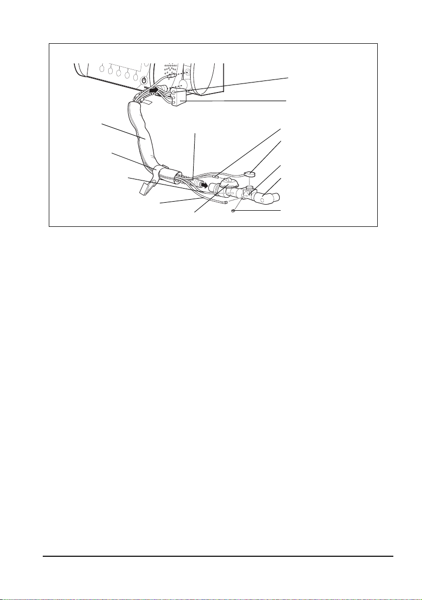
1 Ventilation hose
Hose system (reusable and disposable versions available)
5 BiCheck flow sensor
connection line
10 CO
2
measuring hose
4 PEEP control tube
11 Pressure-
measurement
tube
1 Ventilation hose
7 Elbow
6 BiCheck flow sensor
9 Patient valve
12 Velcro strap
with clip
2 Water filter for CO2
measurement
3 Connector
8 Blanking plug
13 Tube
protection
sleeve
The respiratory gas flows through the ventilation
hose to the patient valve.
2 Water filter for CO2 measurement
The water filter protects the measuring chamber
of the MEDUMAT Transport against moisture and
contamination from the patient's respiratory gas.
3 Connector
The measurement-tube system is connected to
MEDUMAT Transport by means of this connector.
4 PEEP control tube
With this tube, MEDUMAT Transport controls the
patient valve and the PEEP.
5 BiCheck flow sensor connection line
This electric lead transfers the measuring signals
from the BiCheck flow sensor to the MEDUMAT
Transport.
6 BiCheck flow sensor
This sensor supplies monitoring data on flow,
MV
, Vte and f.
e
7 Elbow
The mask/tube is connected here. The elbow is
removable, i.e., the mask/tube can also be
Notice:
Detailed information about the hose systems can be found in the "Patient Hose
System" instructions for use WM 66696.
8 EN Overview
connected to the BiCheck flow sensor itself,
depending on the position of the patient.
8 Blanking plug
The blanking plug (Luer lock) is used to seal off
the CO
outlet if your MEDUMAT Transport is not
2
equipped with CO
activated.
9 Patient valve
Switchover between inspiration and expiration
happens here.
10 CO2 measuring hose
Test gas is removed via this tube if your unit is
equipped with the optional CO
facility.
11 Pressure- measurement tube
For patient-side measurement of ventilation
pressure.
12 Velcro strap with clip
Used for fixing the patient hose system to the
patient's clothing.
13 Tube protection sleeve
Protects tubes and leads against soiling and
damage.
measurement or this is not
2
measurement
2
Page 9
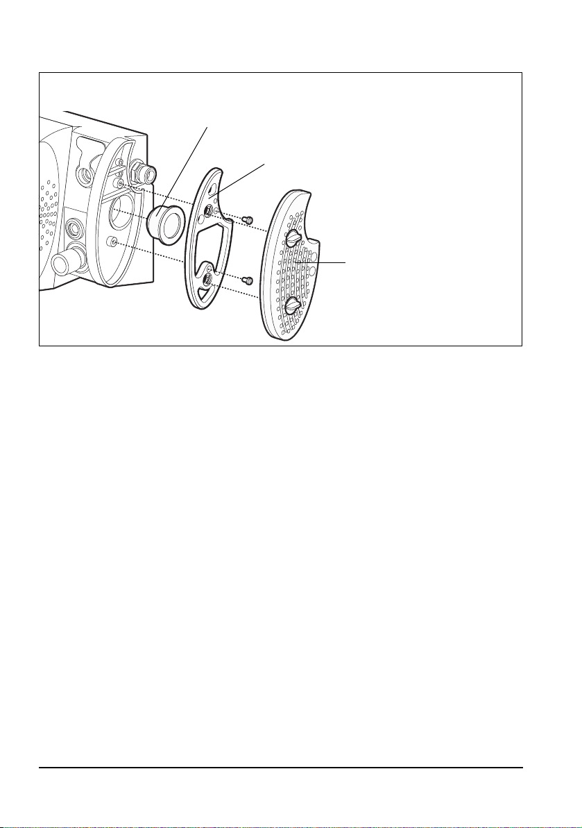
1 Filter grommet
Hygiene input filter (optional)
3 Hygiene input filter
2 Filter mount
1 Filter grommet
Holds the suction filter in position.
2 Filter mount
For installing a hygiene input filter in the device.
3 Hygiene input filter
Protects the device from viral and bacterial
contamination.
Overview EN 9
Page 10
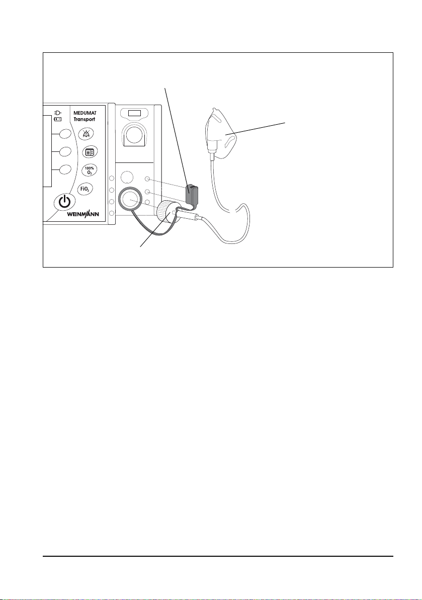
1 Cover
Inhalation adapter
2 Inhalation mask
3 Inhalation adapter
1 Cover
Blocks the top two measuring ports on the device
during inhalation.
2 Inhalation mask
The patient inhales oxygen through the inhalation mask.
3 Inhalation adapter
For connecting an inhalation mask to the device.
10 EN Overview
Page 11

MEDUMAT Transport Main menu
Alarm limits
AActivate automatic alarm limits
Curves
Audio/Video
Options
Night colors
PPr essure, flow
Pressure, CO
2
Pressure, flow, CO
2
Pressure, flow,
measurements
Pressure, CO
2
,
measurements
Pressure gauge
Automatic alarm limits
MVe n
MVe p
f n
Apnea
etCO
2
n
etCO
2
p
Advanced ventilation parameters
Brightness/Day
Brightness/Night
Brightness/NVG
Volume
Alarm LED
Year
Month
Day
Hour
Minute
CO2 configuration
Date, time
Device data
Pressure ramp
Flow ramp
Flow progress
decreasing
constant
Plateau time
Trigger thresholds
Inspiration
Expiration
Trigger time slot
Apnea ventilation parameters
AActivated
Apnea mode
BiLevel + ASB
SIMV + ASB
Settings
PEEP
pInsp
Vt
Freq
I:E
Suction activated
Unit
mmHG
Vol%
kPa
Med. O
Compressed air
Concentrator O
Bluetooth
Compressed gas supply
Hygiene input filter
NVG
MEDUMAT Transport Main menu
Overview EN 11
Page 12

Mode menu
NIV
BiLevel + ASB
aPCV
PCV
CPAP + ASB
PRVC + ASB
IPPV
S-IPPV
SIMV + ASB
Inhalation
Pre-oxygenation
Symbols used on the display
12 EN Overview
Symbol Meaning
Emergency mode – Infant (up to approx. 1 year)
Emergency mode – Child (approx 1-12 years)
Emergency mode – Adult (approx 13 years and over)
Battery status indicator
Page 13

Symbol Meaning
Tick box: option activated
Radio button: function selected
Navigate upwards
Navigate downwards
Increase value
Decrease value
Confirm your selection
Navigation knob active
Bluetooth connection:
– Symbol is gray when connection has been activated
– Symbol is blue during communication
Acoustic alarm output activated
Acoustic alarm output deactivated
Alarm volume set to < 50%
Overview EN 13
Page 14

Symbol Meaning
Acoustic alarm output permanently muted (NVG mode only)
Time
Trigger time slot
14 EN Overview
Page 15

Function of the controls during ventilation
1 2 345
6
7
8
Depending on the ventilation mode selected, you can set the following ventilation
parameters using the controls:
Ventilation
mode
BiLevel +
ASB
aPCV
PCV
CPAP + ASB
PRVC + ASB
IPPV
S-IPPV
Control
knob
PEEP pInsp pMax Freq.
PEEP pInsp pMax
PEEP pInsp pMax Freq.
PEEP - pMax -
PEEP Vt pMax Freq.
PEEP Vt pMax Freq.
PEEP Vt pMax Freq.
1
Control
knob 2
Control
knob 3
Control
knob 4
Freq.
Navigation
knob 5
I:E and
Selection/
Confirmation
I:E and
Selection/
Confirmation
I:E and
Selection/
Confirmation
Only Selection/
Confirmation
I:E and
Selection/
Confirmation
I:E and
Selection/
Confirmation
I:E and
Selection/
Confirmation
Function
button 6
Δ
pASB Trigger Mode
Trigger
time slot
--Mode
Δ
pASB Trigger Mode
Δ
pASB Trigger Mode
--Mode
- Trigger Mode
Function
button 7
Trigger Mode
Function
button 8
Overview EN 15
Page 16

Ventilation
mode
SIMV + ASB
Inhalation
Pre-
oxygenation
Control
knob
PEEP Vt pMax Freq.
----Flow --Mode
----Flow --Mode
1
Control
knob 2
Control
knob 3
Control
knob 4
Navigation
knob 5
I:E and
Selection/
Confirmation
Function
button 6
Δ
pASB Trigger Mode
Function
button 7
button 8
Function
16 EN Overview
Page 17

Special markings
MEDUMAT Transport
Battery
1 MEDUMAT Transport type plate
3 STK and service label
9 Cover of USB interface
8 Filter compartment
cover
6 O2/AIR inlet/outlet
2 Voltage input
5 Ventilation hose connection
4 Follow the instructions for use
7 O2/AIR inlet
10 Rechargeable battery type plate
Hygiene input filter (optional)
11 Hygiene input filter
Symbol Meaning
1
1
MEDUMAT Transport type plate
Consult instructions for use
Date of manufacture
1
Degree of protection against electric shock: type BF device
1
Input
Overview EN 17
Page 18
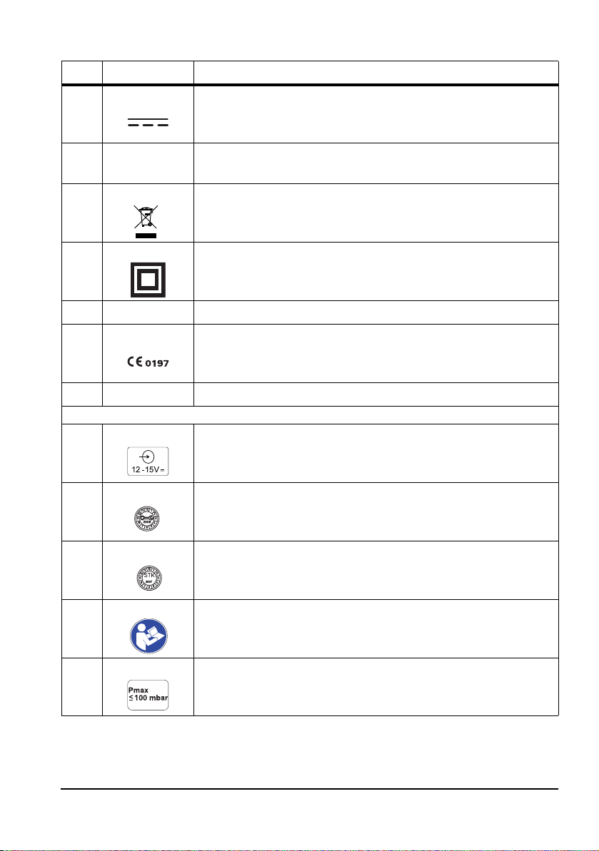
Symbol Meaning
1
DC voltage
1
1
1
1
1
1
Other marks
2
3
3
4
I
min
I
max
IPX4
SN
Minimum and maximum current
Do not dispose of the unit in the household waste.
Type of protection against electric shock: protection class II device
Protection against ingress of water
CE mark (confirms that the device complies with the applicable European
Directives).
Serial number
Input voltage
Service label: indicates when the next service is required.
STK label: (only in the Federal Republic of Germany) indicates when the
next safety check in accordance with §6 Medical Device Operator
Ordinance (MPBetreibV) is required.
Follow the instructions for use
5
18 EN Overview
Maximum pressure ≤ 100 mbar
Page 19

6
O2 / AIR
7
8,9
10
10
10
10
Symbol Meaning
270 – 600 kPa
80 – 150 l/min
Volume flow rate
Input 2.7 bar–6 bar O2 or sterile compressed air
Consult instructions for use
Rechargeable battery type plate
Do not dispose of the unit in the household waste.
Do not subject the unit to hard knocks or shocks.
Do not open the unit using force.
Protect the unit against heat.
10
Protect the unit against moisture.
Overview EN 19
Page 20

Symbol Meaning
3
Hygiene input filter (optional)
11
Input
Consult instructions for use
Do not reuse
Labeling on the packaging
Symbol Meaning
MEDUMAT Transport:
SN
Serial number of the unit
Permissible storage temperature: -30°C to +70°C
RH % 0-95
Permissible humidity for storage: up to 95% relative humidity
Safety information in these instructions for use
The safety instructions in these instructions for use are marked as follows:
Warning!
Warns of risk of injury and possible damage to the unit.
Caution!
Warns of material damage and possibly incorrect therapy results.
Notice:
Offers useful tips.
20 EN Overview
Page 21

2. Description
2.1 Intended use
The MEDUMAT Transport is an automatic oxygen ventilator with additional preoxygenation and monitoring functions (pressure, flow and CO
MEDUMAT Transport is used for the controlled and assisted, as well as invasive and non-invasive, ventilation of adults, children, and infants.
tidal volumes of 50ml or more are possible. Smaller tidal volumes are also possible in the
case of pressure-controlled ventilation.
MEDUMAT Transport must only be operated when installed permanently or on approved portable systems.
In the case of volume-controlled ventilation,
2.2 Applications
MEDUMAT Transport can be used in the following cases for up to 30 days:
Emergency
• for resuscitation at the place of the emergency
• for longer-tem use in continuing emergency situations
• for preoxygenation via a ventilation mask
• for inhalation via an oxygen mask or nasal cannula
).
2
Transport
• in ground, sea and air emergency medical service
• between hospital rooms and departments
• between a hospital and other locations (secondary transport)
Ventilation in hospitals
• recovery room
• intensive care unit
• surgery preparation and follow-up
• emergency department
MEDUMAT Transport is also suitable for gentle ventilation of anesthetized patients (TIVA:
total intravenous anesthesia).
Description EN 21
Page 22

2.3 Operator and user qualification
MEDUMAT Transport must only be used by persons who can verify that they have the
following qualifications:
• A medical qualification and training in ventilation techniques
• Training in the use of the MEDUMAT Transport by a person authorized
by WEINMANN Emergency
Improper use may lead to serious physical injury.
As the operator or user, you must be fully familiar with the correct operation of this medical
device. Observe the statutory requirements for operation and use (in Germany, particularly
the German regulations governing owners/operators of medical devices (MPBetreibV)).
General recommendation: You should seek instruction on the correct handling, use and
operation of this medical device from a person authorized by WEINMANN Emergency.
2.4 Function
The unit
MEDUMAT Transport is used to treat apnea and to provide respiratory support. By means
of adjustable ventilation parameters, the unit ensures uniform ventilation tailored to the
patient.
Pressure-controlled and volume-controlled ventilation modes can be selected for optimum
patient ventilation.
In CPAP + ASB mode, the unit enables assisted spontaneous breathing with continuous
positive airway pressure and respiration-controlled oxygen inhalation. In addition, the unit
permits O
The unit allows the oxygen concentration of the respiratory gas to be adjusted.
Depending on the version, the unit's large display can show up to three spirometric curves
(pressure, flow and CO
For emergency situations, rapid selection of default types of ventilation is possible.
With the data communication option enabled, the device can transmit its application data
to an application documentation system via Bluetooth.
inhalation for preoxygenating the patient.
2
) or two curves and additional measured values.
2
22 EN Description
Page 23

Patient Hose System
The ventilation gas is supplied to the patient via the Patient Hose System, comprising the
ventilation hose and all leads necessary for comprehensive ventilation and monitoring.
The Patient Hose System is designed to permit spontaneous respiration even if the
MEDUMAT Transport malfunctions.
The following versions of the patient hose system are available:
• Reusable hose system with CO
• Reusable hose system without CO
• Disposable hose system with CO
• Disposable hose system without CO
• Disposable hose system with reduced dead space with CO
measuring hose
2
measuring hose
2
measuring hose
2
measuring hose
2
measuring
2
hose
• Disposable hose system with reduced dead space without CO
2
measuring hose
• Disposable hose system with reduced dead space with CO
measuring
2
hose for adults and children
• Disposable hose system with reduced dead space without CO
2
measuring hose for adults and children
Hygiene input filter (optional)
For ventilation in a contaminated atmosphere, MEDUMAT Transport can be used with a
hygiene input filter. This protects the device from viral and bacterial contamination.
Inhalation adapter
The ventilation gas can alternatively be supplied to the patient via the inhalation adapter
and the inhalation hose. During inhalation the measuring ports on the device are blocked
by a cover so the device does not take in ambient air.
Description EN 23
Page 24

3. Safety information
Read these instructions for use carefully. It is part of the unit and must be available at all
times.
For your own safety and that of your patients, and in accordance with the requirements of
Directive 93/42/EEC, please observe the following points:
General
• Always carry out a functional check before using the unit
(see "10. Function check" on page 115).
• Please observe the section "9. Hygienic preparation" on page 109 in
order to avoid infection or bacterial contamination.
Warning!
• Risk of injury. Only use MEDUMAT Transport if you are a qualified
medical professional and have received training in respiration
techniques. Improper use may lead to serious physical injury.
• Risk of injury. Never leave the patient or the ventilator unattended during
ventilation. Only then can you respond quickly if the patient's condition
deteriorates or in the event of an alarm or malfunction. Delayed response
on the part of medical personnel may lead to serious physical injury.
• Risk of injury from deactivated alarm LED, deactivated acoustic alarm
output and darkened display in NVG mode!
The alarms are barely perceptible as a result of the deactivated alarm
LED, the deactivated acoustic alarm output and the darkened display in
NVG mode. This can injure the patient.
– Always monitor the patient during ventilation.
– Only use the NVG option in the military sector.
• Only use MEDUMAT Transport for the designated purpose
(see "2.1 Intended use" on page 21).
• MEDUMAT Transport is not suitable for hyperbaric use (pressure
chamber).
• The unit is not licensed for use in explosive atmospheres. The unit must
not be used in combination with flammable gases or anesthetics.
• The unit is not licensed for use in poisonous atmospheres.
• Only operate the unit in a contaminated atmosphere with a hygiene input filter.
24 EN Safety information
Page 25

• Only operate the unit with a filter compartment cover or hygiene input
filter to prevent any liquids from entering the unit.
• Always keep the air inlet openings on the filter compartment cover or the
suction inlets on the hygiene input filter clear.
• Only have modifications to the unit carried out by the manufacturer,
WEINMANN Emergency, or by a technician expressly authorized by
WEINMANN Emergency.
Caution!
• Do not place a switched-on cellular phone or radio closer than 1 m from
the MEDUMAT Transport, as this could cause malfunctions.
• Remember that the respiratory resistance of the system as a whole may
increase beyond the level specified by the standard when an HME filter
(heat and moisture exchanger), a bacterial filter or a combined HME
bacterial filter is used. Please also follow the manufacturer's instructions
for use for the filter being used.
• When operating the unit with the power supply unit, always connect the
unit to an easily accessible outlet so that it can be unplugged quickly in
the event of a malfunction.
• When operating the unit with the power supply unit, make sure that the
power cord cannot cause anyone to trip or cause any obstruction. If
necessary, do not use an external power supply, but operate the unit
with the battery instead.
• When operating the unit with the 12 V supply cord, always connect the
unit to an easily accessible vehicle electrical system receptacle so that it
can be unplugged quickly in the event of a malfunction.
• When operating the unit with the 12 V supply cord, make sure that the
cord cannot cause anyone to trip or cause any obstruction. If necessary,
do not use the vehicle electrical system, but operate the unit with the
battery instead.
• An alternative ventilation unit must be kept available in case a unit fails.
• After using the unit in a dusty environment (e.g., a gravel plant), change
the suction filter (see "12.5 Changing the suction filter" on page 131) or
the hygiene input filter (see "12.6 Changing the hygiene input filter" on
page 132).
• Only operate a unit with hygiene input filter with software version 6.1 or
higher.
Safety information EN 25
Page 26

Safe handling of oxygen
Warning!
• Risk of explosion! In combination with combustible substances (grease,
oil, alcohol etc.), highly compressed oxygen may give rise to spontaneous
explosive reactions.
• Risk of fire! If only the O2/AIR inlet/outlet is used, close the O2/AIR inlet
on the side with a suitable cap. Otherwise, gas will escape from the O2/
AIR inlet on the side.
• Risk of poisoning! Highly concentrated oxygen can have a toxic effect on
the patient if administered for too long and depending on the age of the
patient. When ventilating with pure oxygen or an oxygen-air mixture,
make sure that oxygen is only administered for an appropriate period.
• Keep the units and all screwed unions absolutely free from oil and
grease.
• Be sure to wash your hands before working on the oxygen supply.
• Smoking and open flames are strictly prohibited in the vicinity of fittings
containing oxygen.
Caution!
• When assembling the unit, and when changing cylinders, tighten all
screwed unions on the oxygen cylinder and pressure reducer by hand
only. Never use tools. Overtightening damages the threads and seals,
resulting in leaks.
• Secure the oxygen cylinders so that they cannot fall over. If a cylinder falls
on the pressure reducer or valve, these could break off, causing a violent
explosion.
• Risk of insufficient oxygen supply! Two oxygen sources can be connected
to this unit simultaneously. Make sure that only one oxygen source is
open at any given time and that there is no gas reflux. Otherwise, one of
the oxygen sources may empty itself unnoticed. Sufficient oxygen supply
to the patient can then no longer be guaranteed when the unit is in use.
• Always open the cylinder valve slowly to prevent pressure hammer on the
fittings.
• Do not empty oxygen cylinders completely, as this may allow moist
ambient air to enter and cause corrosion.
26 EN Safety information
Page 27

Ventilation/Handling
Caution!
• The USB port on the device must only be used for the application scenarios
outlined in the instructions for use. Only USB sticks which conform to the
USB standard 2.0 should be inserted in the USB port, otherwise this
interferes with operation of the unit, putting the patient at risk.
• Patient and ventilator must be kept under continuous observation during
ventilation.
• Prolonged ventilation can lead to atrophy of the muscles (dependency of
the patient on ventilation).
• Prolonged ventilation may lead to the airway drying out. Ensure
adequate conditioning of the respiratory gas.
• Only apply high ventilation pressures for short periods and only if
medically indicated. Permanently applied high ventilation pressures can
be injurious to the patient.
• Make sure that the patient valve is not covered or its function impaired,
e.g. by the patient's position.
• The patient hose systems for the device have different dead spaces.
Please take the dead space into consideration when selecting the
ventilation parameters, particularly when ventilating infants with very
small tidal volumes. Otherwise, there is a risk of insufficient ventilation.
• Do not place the patient valve of the disposable hose system with
reduced dead space near the O2/Air inlet of the MEDUMAT Transport,
in order to prevent the device sucking in CO
• Please note that the inspiratory resistance of a disposable hose system
with reduced dead space increases during adult ventilation.
• Please note that the use of additional accessories between the ventilation
hose and patient (e.g., humidifiers, nebulizers, and goosenecks) increases the dead space.
• The device is not suitable for the ventilation of premature babies (born
before the end of the 36th week of pregnancy).
• Please note that if concentrator oxygen with an oxygen concentration
outside of the specifications is used (see 14.1, page 142), the tolerances
specified for the O
measurement may also vary.
2
• Risk of injury from switching on a device with activated NVG mode
during daylight or without a night vision device!
A device with activated NVG mode cannot be used straight away during
daylight or without a night vision device. This can injure the patient.
– Keep an alternative ventilation unit at the ready.
.
2
Safety information EN 27
Page 28

• When performing ventilation with a tidal volume Vt < 200 ml, a
PEEP > 0 mbar and an inspiratory O
the inspiratory O2 concentration administered can deviate from the set
value. Reduce the PEEP to decrease the administered inspiratory O2
concentration.
concentration set to FiO2 <70%,
2
Patient Hose System
Warning!
• Risk of injury. Only use the Patient Hose System if you are a qualified medical
professional and have received training in respiration techniques. Improper use
may lead to serious physical injury.
• The Patient Hose System must be subjected to a functional check and visual
inspection by the user before use. For this, refer to the instructions for use for
the Patient Hose System.
• When connecting the patient valve, check that the direction of flow of the
respiratory gas is correct. Make sure that the expiration opening of the patient
valve is not covered or prevented from functioning, e.g., by the patient's
position.
• Only use the Patient Hose System for the purpose described. For this, refer to the
instructions for use for the Patient Hose System.
• The Patient Hose System is not suitable for hyperbaric use (pressure chamber).
• Also refer to the instructions for use for the Patient Hose System.
Software
• Risks due to software errors have been minimized by means of extensive
qualification measures.
• This unit‘s software contains code which is subject to the GPL. You will
receive the source code and the GPL upon request.
Accessories/Repairs/Replacement parts
Caution!
• Protect silicone/rubber parts against UV light and prolonged direct
exposure to sunlight to prevent them becoming brittle.
• We recommend that work such as inspections and repairs should be
carried out by the manufacturer, WEINMANN Emergency, or by a
technician expressly authorized by WEINMANN Emergency.
28 EN Safety information
Page 29

• If third-party items are used, functional failures may occur and fitness for
use may be restricted. Biocompatibility requirements may also not be
met. Please note that in such cases, any claim under warranty and liability
will be voided if neither the accessories nor genuine replacement parts
recommended in the instructions for use are used.
• This product may contain disposable items. Disposable items are intended
to be used only once. So use these items only once and do not reprocess
them. Reprocessing disposable items may impair the functionality and
safety of the product and lead to unforeseeable reactions as a result of
ageing, embrittlement, wear, thermal load, the effects of chemical
processes, etc.
Safety information EN 29
Page 30

4. Installation
As a rule, MEDUMAT Transport only has to be installed for stationary use in rescue vehicles,
helicopters or aircraft. In this case, fastening sets can be supplied as accessories.
If MEDUMAT Transport is supplied complete on a portable system, the unit is ready for
operation and no further installation work is required. There are separate instructions for
use for the portable systems.
Warning!
After installation, you must perform a functional check (see "10. Function check" on
page 115) to ensure reliable operation.
4.1 Connecting oxygen cylinder
Warning!
• Risk of explosion! Wash your hands thoroughly before doing any work
on the oxygen supply. Hydrocarbon compounds (e.g. oil, grease,
cleaning alcohol, hand cream or adhesive plasters) can cause explosive
reactions if they come into contact with highly compressed oxygen.
• Never use wrenches or other tools to tighten or unscrew the union nuts.
Notice:
Only use the High Flow OXYWAY Fast II and OXYWAY Fix III pressure reducers on the
MEDUMAT Transport. Foreign pressure reducers can impair the unit's efficiency.
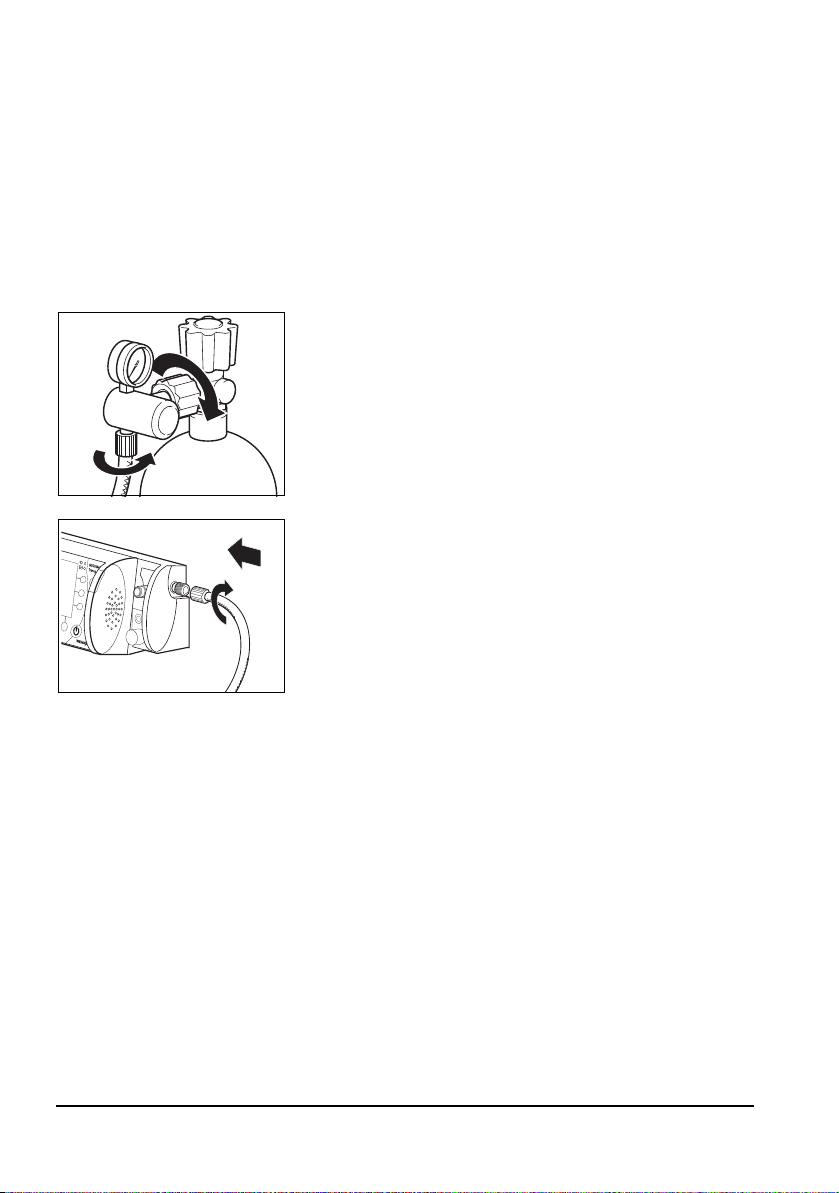
Removing the empty cylinder
1. Close the valve on the oxygen cylinder.
2. Switch MEDUMAT Transport off again.
3. Undo the screwed union at the cylinder by hand.
30 EN Installation
Switch on MEDUMAT Transport at the On/Standby/Off
switch. This allows the remaining oxygen to escape and
the unit is pressure-free. Only when the contents gauge
on the pressure reducer indicates 0 bar, can the
screwed union be undone by hand.
Page 31
Connecting a new cylinder
1. Briefly open the valve of the new oxygen cylinder, then shut it again. This is to blow
away any particles of dust.
Caution!
• Make sure that the patient is not connected up to the MEDUMAT
Transport when you are establishing the gas supply. Otherwise, the
unit's automatic self-test can lead to incorrect results.
• When doing this, hold the valve opening away from your body in such a
way that any flying particles cannot injure yourself or other people!
2. Screw the pressure reducer to the cylinder valve using
the knurled union nut. Tighten the union nut by hand.
3. Screw the pressure hose onto the outlet of the pressure
reducer (if not already connected) using the G 3/8
union nut.
4. Screw the other end of the pressure hose to the
compressed gas connection of the MEDUMAT
Transport (if not already connected).
Connecting a second oxygen source
Caution!
Risk of insufficient oxygen supply
Two oxygen sources can be connected to this unit simultaneously. Make sure that only
one oxygen source is open at any given time and that there is no gas reflux. Otherwise,
one of the oxygen sources may empty itself unnoticed. Sufficient oxygen supply to the
patient can then no longer be guaranteed when the unit is in use.
If desired or if foreseen in your establishment, you can connect a second oxygen source,
e.g., an oxygen cylinder or a CGC to the O2/AIR inlet/outlet (quick connector to the front
of the unit).
Notice:
If your unit is equipped with a DIN quick connector, no oxygen can be fed into the
unit with the associated DIN gas probe. With this combination it is only possible to
draw off oxygen.
Installation EN 31
Page 32
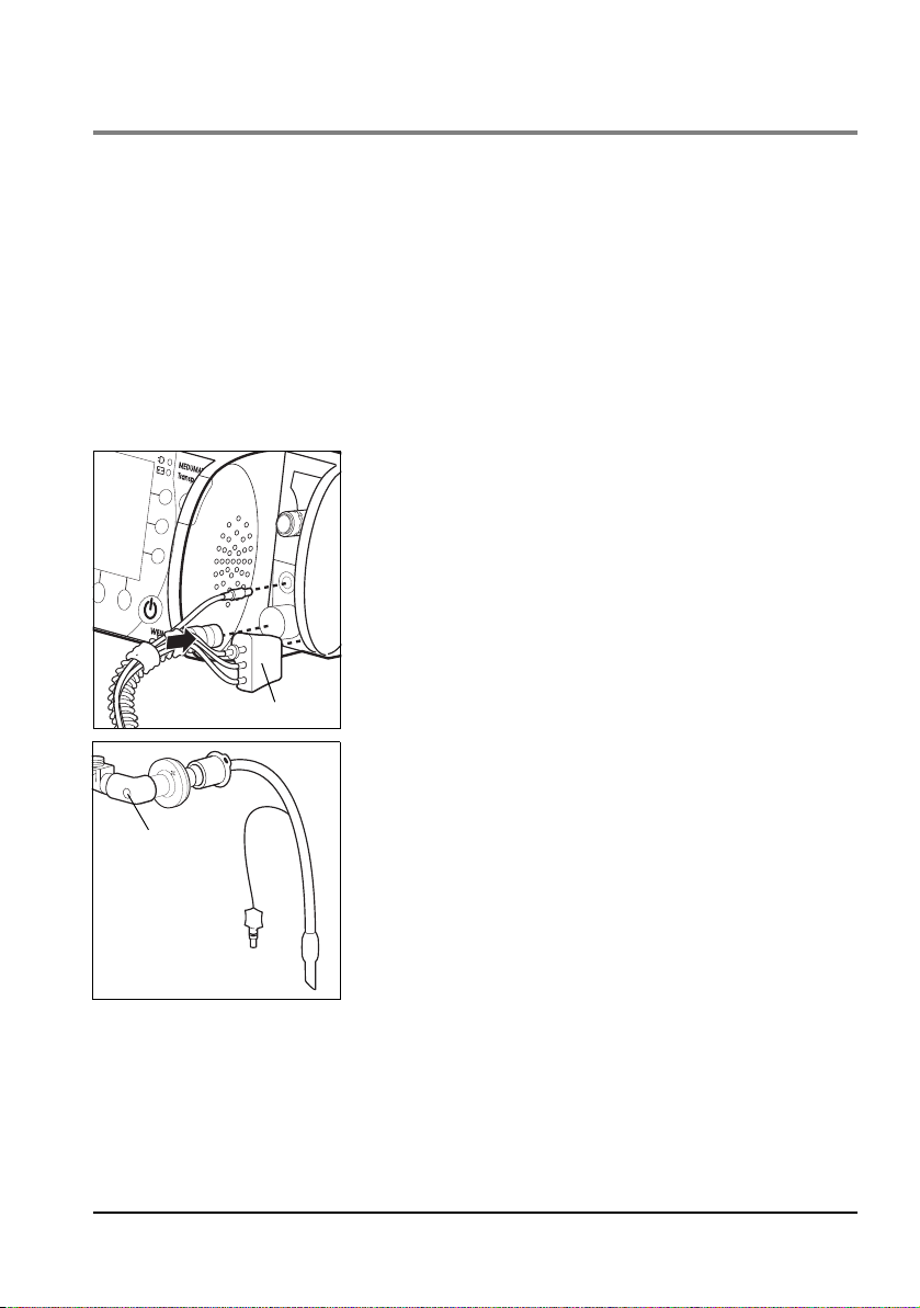
4.2 Connecting the hose system
Connector
Elbow
Caution!
Risk of injury posed by ventilation with inhalation mask, tube or inhalation cannula!
Before ventilating a patient, ensure that no inhalation mask, tube, or inhalation
cannula is being used for the ventilation. Otherwise, ventilation with a connected
inhalation mask, tube, or inhalation cannula could injure the patient.
A reusable hose system is supplied with the MEDUMAT Transport . Alternatively, a
disposable hose system and a disposable hose system with reduced dead space are also
available. Information on the disposable hose system with reduced dead space can be
found in the instructions for use for the patient hose system WM 66696. To connect
reusable and disposable hose systems, proceed as follows:
1. Press the ventilation hose onto the corresponding
connection on the unit.
2. Attach the connector of the BiCheck flow sensor
connection line to the corresponding connection on the
unit.
3. Press the connector (contains PEEP control line, CO
measuring hose, pressure-measurement tube) onto the
corresponding connection on the unit. Make sure that
the connected tubes are not kinked.
Caution!
Only grip the ventilation hose by its ends. Otherwise the
hose may be damaged.
4. Connect the patient valve with BiCheck flow sensor to
the hose following intubation. If performing mask
ventilation, attach the ventilation mask to the patient
valve with the BiCheck flow sensor (identical to tube
connection).
2
32 EN Installation
Page 33
Notice
Elbow
You can remove the elbow to reduce the dead space or
to adapt the hose routing to suit the patient's position.
Hose protection sleeve
The tube protection sleeve is pulled over the ventilation
hose with connected BiCheck flow sensor. It prevents the
hose system from tangling on other items of equipment
and being damaged.
Water filter for CO2 measuring hose
Notice:
Always operate the unit with a water filter when CO
particles that have been sucked in can damage the CO
The water filter WM 97012 loses efficiency after approx. 8 hours of continuous operation,
depending on the temperature, humidity and any coarse particles such as mucus.
Change the filter after eight hours at the latest.
The filter's decreasing efficiency is indicated by the alarm message "CO
display. This message is accompanied by a medium-priority audible alarm.
suction is activated. Otherwise
2
module.
2
occlusion" on the
2
Installation EN 33
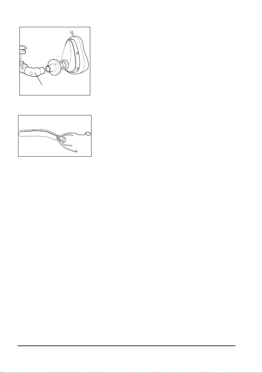
Page 34
4.3 Connecting the inhalation adapter
An inhalation adapter for oxygen inhalation via the MEDUMAT Transport is supplied with
the unit. The inhalation mode is used for administering a defined oxygen flow of
1-10 l/min via a suitable interface.
On delivery, the inhalation adapter is secured to the connection for the ventilation hose by
a retaining band. To connect the inhalation adapter, proceed as follows:
1. Connect the inhalation adapter to the ventilation hose
port on the unit.
or
Connect the inhalation adapter to the patient-side port
of the patient hose system.
2. To block the measuring ports on the device during
inhalation, place the cover on the inhalation adapter on
the upper two measurement ports on the device.
Notice
The cover is not required when connecting the inhalation adapter to the patient-side port of the patient hose system. In this case, the connection plug
of the measuring hose system blocks the measuring ports instead.
34 EN Installation
Page 35
4.4 Accessories from other manufacturers
Caution!
• The USB port on the device is only intended for the application scenarios
outlined in the instructions for use. Only USB sticks which conform to the
USB standard 2.0 should be inserted in the USB port. Any other use will
interfere with operation of the unit, putting the patient at risk.
• Please note that the use of additional accessories between the ventilation
hose and patient (e.g., humidifiers, nebulizers, and goosenecks)
increases the dead space.
Accessories Assembly Special features
HME filter If a filter is used, install it
Bacterial filter
Combined HME bacterial filter
Ventilation mask
Laryngeal mask
Laryngeal tube
Gooseneck
Endotracheal tube
Tracheostomy tube
Humidifier*
Nebulizer**
between the patient connection
of the BiCheck flow sensor (with
elbow if desired) and the tube or
mask.
Onto the BiCheck flow sensor
If a humidifier is used, install it
between the patient connection
of the BiCheck flow sensor and
the tube/mask.
If a nebulizer is used, install it
between the patient connection
of the HME filter, bacteria filter
or the combined HME bacterial
filter and the tube/mask (with
elbow if desired)
*Not all types of humidifiers are suitable for use with MEDUMAT
Transport. Always ensure that all products are compatible.
**Not all types of nebulizers can be used effectively with
MEDUMAT Transport. Always ensure that all products are
compatible.
Follow the manufacturer's
instructions.
Requires standard connection as
per ISO 5356-1
Requires standard connection as
per ISO 5356-1
Follow the manufacturer's
instructions for use
Requires standard connection as
per ISO 5356-1
Follow the manufacturer's
instructions for use
Installation EN 35
Page 36

Assembling the nebulizer
Caution:
When assembling the nebulizer, observe the correct order of the individual
components. Always install an HME filter, a bacteria filter, or a combined HME
bacterial filter between the BiCheck flow sensor and the nebulizer. If the filter is not
installed correctly or no filter is used, the membranes in the patient valve may
become stuck together and cause the BiCheck flow sensor to deliver faulty
measurements.
1. Attach the mask/tube (with elbow if desired) to the nebulizer.
2. Connect the open end of the nebulizer to the HME filter, bacteria filter or the combined
HME bacterial filter.
3. Attach the HME filter, bacteria filter, or combined HME bacterial filter to the BiCheck
flow sensor of the patient hose system.
Supplying oxygen to external units
You can use the O2/AIR inlet/outlet to connect units, modules or inhalation devices to the
MEDUMAT Transport (quick connector to the front of the units).
When doing so, bear in mind that the outlet gas flow reduces the efficiency of the gas
supply (see "14.6 Possible O
36 EN Installation
concentration with counterpressure" on page 149).
2
Page 37

4.5 Permanent installation of the unit
Back panel of
MEDUMAT Transport
Portable system
If you wish to install the unit on a portable system or permanently install it in a vehicle or
aircraft, you require the fastening set WM 15730. The following diagram shows the
method of installation.
Installation EN 37
Page 38

5. Operation
Function
buttons with
fixed
assignment
5.1 Controls
Display
The display provides the following information while the
unit is in use.
• Progress of the current ventilation
• Current measurements and alarm limits
• Ventilation parameters set/to be set
• Current assignment of the context-dependent
function buttons and control knobs
• Alarms and error messages
Function buttons with fixed assignment
The fixed-assignment function buttons enable you to carry
out the following functions directly:
• Mute acoustic alarms / open alarm menu
• Call up the main menu
• Activate the "100% O
• Call up the "O
" function
2
concentration" menu
2
38 EN Operation
Notice:
Pressing the alarm mute button and the menu
button simultaneously takes a screenshot of the
current image on the screen. The following
message then appears on the screen: "Taking
screenshot "#", please wait" (see "8.3 File Export/
Import" on page 101).
Page 39
Context-dependent function buttons
Function buttons
for emergency
ventilation
Context-
dependent
buttons
1
2
3
1
2
3
Context-
dependent
buttons
Context-
dependent
buttons
4
5
6
On both sides of the display there are context-dependent
function buttons for calling up the following functions:
Left side of the display:
• Selecting emergency modes (available in every
ventilation mode):
– Infant (up to approx. 1 year)
– Child (approx. 1-12 years)
– Adult (approx. 13 years and over)
Right side of the display:
• Calling up menus during ventilation:
– Button 1: Selecting a ventilation mode (see "6.
Ventilation modes" on page 63)
– Button 2: Setting trigger thresholds in
BiLevel + ASB, aPCV, CPAP + ASB, PRVC + ASB,
S-IPPV and SIMV + ASB modes
(see "Trigger thresholds" on page 88)
– Button 3: Setting ASB (Assisted Spontaneous
Breathing) pressure support in BiLevel + ASB, CPAP
+ ASB, PRVC + ASB, SIMV + ASB modes or trigger
time slot in aPVC mode
• Navigating in a menu:
– Button 1: Up
– Button 2: Down
– Button 3: Confirm selection
Alternatively, these settings can also be made with the
navigation knob (dual navigation).
• Setting a parameter:
– Button 1: Increase value
– Button 2: Decrease value
– Button 3: Confirm selection
Alternatively, these settings can also be made with the
navigation knob (dual navigation).
Operation EN 39
Page 40

Navigation knob
Navigation knob
1 2345
When a menu is open, you can use the navigation knob to
navigate as follows:
• Turn anticlockwise: moves the selection bar
upwards in the menu
• Turn clockwise: moves the selection bar
downwards in the menu
• Press the navigation knob: confirms selection
When no menu is open, you can carry out the following
functions:
• Confirm setting parameters that have been set
with the context-dependent control knobs
• Set and confirm the I:E ratio
• Set and confirm the flow during inhalation and
pre-oxygenation
Context-dependent control knobs
Depending on the ventilation mode selected, you can set
the following parameters using the control knobs (see
"Function of the controls during ventilation" on page 15):
• Control knob 1: PEEP
• Control knob 2: Vt, pInsp; in some ventilation
modes, this knob has no function
• Control knob 3: pMax (alarm limit)
• Control knob 4: Respiratory rate (no function in
some modes)
• Navigation knob 5: I:E (no function in some modes)
or flow during inhalation and pre-oxygenation
If you change the ventilation parameters with the control knobs, the corresponding
parameters and the symbol above the navigation button will flash for 5 seconds.
If you do not confirm the changed parameters with the navigation button or the contextdependent button within 5 seconds, they will not be applied.
40 EN Operation
Page 41
Above the navigation knob the unit also displays values
On/Standby/Off button
dependent on the ventilation parameters:
Ventilation
parameters
I:E T
Freq.
Vt
Additionally displayed values
i
and MV
T
i
I:E and MV (with Freq. of
≤5/min)
MV
If certain values fall above or below the ventilation
parameters, the corresponding ventilation parameter
flashes red (see "6.2 Important ventilation parameters" on
page 65).
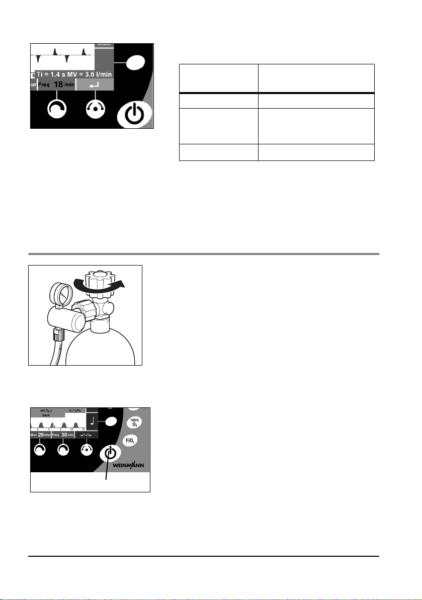
5.2 Switching the unit on/Self-test
1. Open the valve on the oxygen cylinder slowly. The
contents gauge now indicates the cylinder pressure.
2. Calculate the remaining operating time if necessary
(see "5.14 Calculating the Oxygen level/Operating
time" on page 57). You should change the cylinder in
good time, e.g., when the pressure falls below 50 bar,
to ensure a sufficiently long operating time.
3. To switch on MEDUMAT Transport, press the On/
Standby/Off button. An automatic self-test runs which
includes the following sequence of steps:
• Alarm LED flashes briefly
• Alarm buzzer emits a series of five audible sounds
• Loudspeaker emits a series of two audible sounds
• Ventilator checks its own functions internally
Operation EN 41
Page 42

The self-test is successful when all the steps have been
completed. Check that all the steps are successfully
completed. Do not operate the unit if:
• one of the first three steps has not been
successfully completed
• the last part has not been successfully completed
("Fault" message appears in the display)
Caution!
The automatic self-test is not a substitute for a function
check. Before using the unit, always carry out a
function check as described in section"10. Function
check"on page 115. This is the only way to ensure that
the unit is fully functional.
4. The "Start menu" appears in the display. You now have
the following options:
– Press one of the emergency buttons (Infant, Child,
Adult): The unit immediately begins ventilation
with the preset parameters.
– Press the "Previous patient" button: The
ventilation settings from the previous patient
appear. Select the appropriate parameters for the
ventilation of the current patient.
Notice:
– If the switch-off time of the device is less than
30 seconds, the device starts ventilation
automatically after a 20-second countdown.
– Press the "New patient" button: Select the
"Adult", "Infant" or "Child" setting. The "Mode"
menu appears. Select the appropriate ventilation
mode and confirm your selection. Use the control
knobs to set the parameters for ventilating the
patient.
42 EN Operation
Page 43
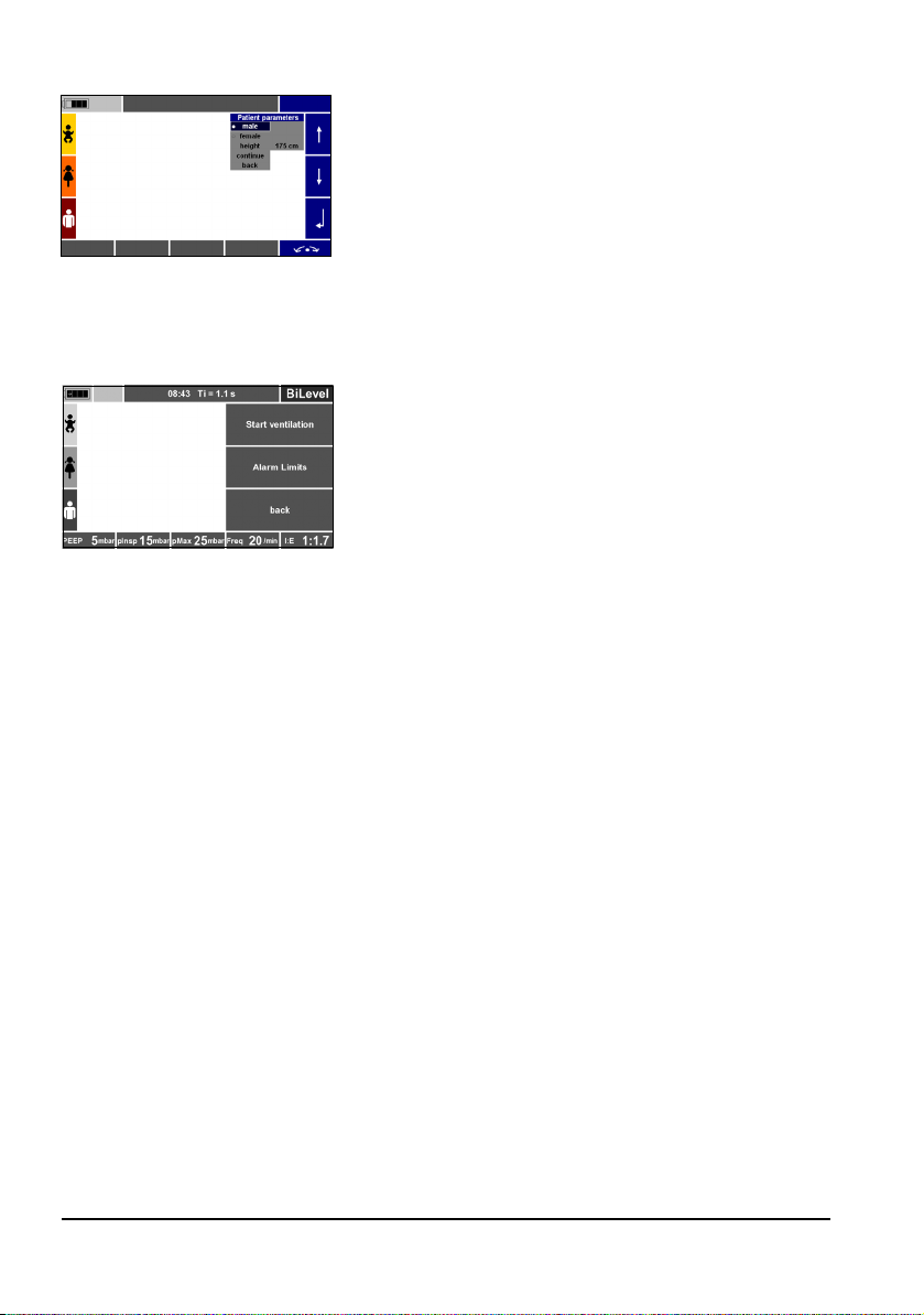
– Press the "New patient" button: Select the
"Height" setting. The "Patient parameters" menu
appears. Select the gender. Set the correct height
with the context-dependent function keys or the
navigation knob. Confirm the setting with
"continue". Now select the appropriate ventilation
mode and confirm your selection. If necessary, use
the control knobs to change the parameters for
ventilating the patient (see "14.8 Calculation of
body weight on the basis of body height" on
page 152).
Then use the context-dependent buttons to select
"Start ventilation" if you want to start ventilation,
"Alarm Limits" if you want to determine the alarm
limits in the "Alarm Limits" menu (see "7.2 Alarm
Limits" on page 85) or "back" if you want to
change any settings.
Notice:
As soon as you select a new patient, you can use
the menu button to change over to the main
menu.
– Select "Function check" menu: The unit will begin
the automatic function check (see "10.4
Performing a function check" on page 119).
Notice:
Following the start of ventilation, all alarms are
automatically muted for 120 seconds. This is with
the exception of the technical alarms "Supply
pressure < 2.7 bar", "Battery almost empty", and
"Device malfunction", which cannot be muted.
During this time, visual alarms are still displayed.
5. When the self-test has finished and the ventilation
mode has been set, connect the patient.
6. Adjust the ventilation values if necessary during
ventilation.
Operation EN 43
Page 44

5.3 Navigating in menus
Navigation knob
The vast majority of functions of the MEDUMAT Transport are accessed via menus.
MEDUMAT Transport offers two methods of navigating in these menus:
• using the navigation knob
• using the context-dependent function buttons on the right of the display
You can close menus at any time by pressing the Menu button again. If you do not change
any parameters, the menus close automatically after 20 seconds.
Parameter changes will not be implemented unless they are confirmed with the navigation
knob or context-dependent button .
Navigating with the navigation knob
1. Use the function buttons to select a menu (here: Alarm
Limits).
2. Select a menu item by turning the navigation knob
clockwise (the selection bar moves downwards) or
anticlockwise (the selection bar moves upwards).
3. Confirm your selection by pressing the navigation
knob.
4. To exit a menu, use the navigation knob to select the
menu item "back" and confirm your selection by
pressing the navigation knob.
Proceed in the same way when making numeric
settings (here: Alarm Limits)
– Turn the navigation knob clockwise to raise the
value, and anticlockwise to lower it.
– Press the navigation knob to confirm the newly set
value.
– If you wait or set another ventilation parameter by
mistake, a set value will be rejected.
5. To switch from a sub-menu directly to the ventilation
screen, press the "Main menu" function button again.
44 EN Operation
Page 45

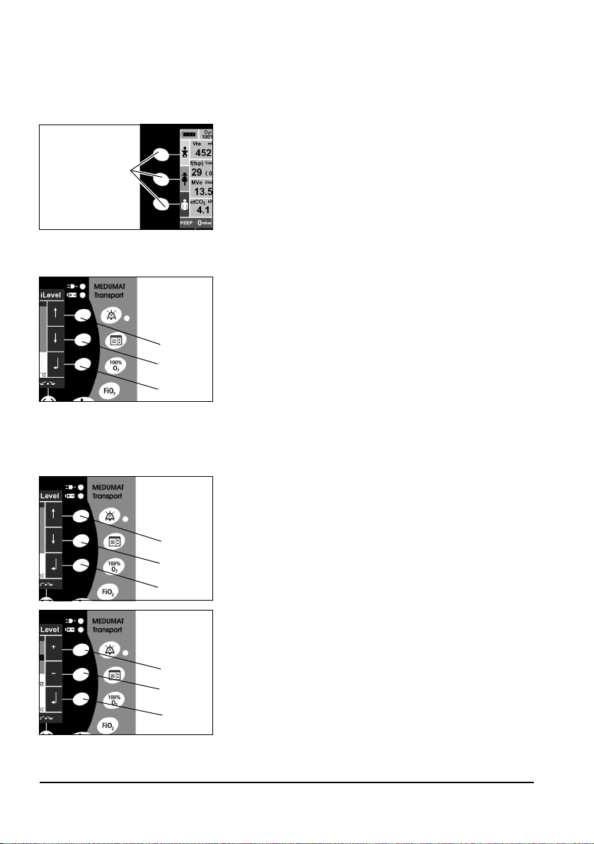
Navigating with the context-dependent function buttons
1. First use the function buttons to select a menu (here:
Main menu).
2. Select a menu item by pressing the function button
(the selection bar moves downwards) or the button
(the selection bar moves upwards).
3. Confirm your selection by pressing the button.
4. To leave a menu, select the menu item "back", using
the or button, and confirm your selection by
pressing the button.
Proceed in the same way when making numeric settings
(here: Alarm Limits)
– Press the button to raise the value and the
button to lower it.
– Press the button to confirm the newly set value.
– If you wait or set another ventilation parameter by
mistake, a set value will be rejected.
5. To switch from a sub-menu directly to the ventilation
screen, press the "Main menu" function button.
Other symbols used in the menus:
Radio button:
If a menu contains functions which have a so-called
"Radio button", only one function at a time can be
selected in these menus.
Tick box:
If a menu contains functions which have a so-called Tick
Box, these functions can be activated in addition to other
functions.
Operation EN 45
Page 46

5.4 Selecting emergency mode
1
2
3
Emergency
ventilation
function
Three modes with preset ventilation parameters are
available for emergency ventilation. You can select these
directly at any time during ventilation by pressing one of
the function buttons twice or by pressing one of the
function buttons once and then confirming with the
navigation knob.
• Button 1: Infant
• Button 2: Child
• Button 3: Adult
If IPPV is selected as the emergency mode, the display
shows a pressure gauge. If BiLevel + ASB is selected as the
emergency mode, the display shows the most recently
used curve display.
Exit the emergency mode as follows:
• Select a mode in the "Mode" menu
• Select the menu item "Curves" in the main menu.
IPPV and BiLevel + ASB can be selected as emergency
modes in the operator menu (see "Emergency Mode" on
page 107). IPPV mode is always preset at the factory. This
mode is activated automatically when you call up an
emergency mode from another ventilation mode.
Emergency ventilation is started with preset parameters. These parameters can be changed
in the operator menu (see "8.2 Ventilation Modes" on page 99) and are optimized for the
following patient groups:
• Infant (up to approx. 1 year, 10 kg body weight)
• Child (approx. 1-12 years, 25 - 30 kg body weight)
• Adult (approx. 13 years and over, 75 kg body weight)
46 EN Operation
Page 47

Factory settings of the unit:
Emergency mode IPPV
Parameter Adult Child Infant
PEEP
pMax
I:E
Frequency
Vt
0 mbar 0 mbar 0 mbar
30 mbar 25 mbar 20 mbar
1:1.7 1:1.7 1:1.7
10/min 20/min 30/min
500 ml 200 ml 60 ml
5.5 Selecting a ventilation mode
To select a different ventilation mode, proceed as follows:
1. Then use the "Mode" function button to select the
"Mode" menu.
2. Then use the navigation knob or the contextdependent function buttons on the right of the display
to select whether you wish to ventilate invasively or
non-invasively.
The device then proposes the possible ventilation
modes to you. The possible ventilation modes for noninvasive ventilation are: BiLevel + ASB, aPCV, PCV and
CPAP + ASB.
3. Then select the required ventilation mode.
Alternatively, you can select the "Inhalation" or
"Pre-oxygenation" function.
4. Confirm your selection by pressing the navigation knob
or the corresponding context-dependent function
button.
If you have selected a volume-controlled mode, and if the tidal volume or ventilation
rate has changed, the device automatically adapts the corresponding alarm limits
(± 30%) before the start of the ventilation. This automated process does not apply if
the parameters are changed during ventilation without the ventilation mode being
changed.
You will find a detailed description of all the ventilation modes in the "Mode" menu in
section "6. Ventilation modes"on page 63.
Operation EN 47
Page 48
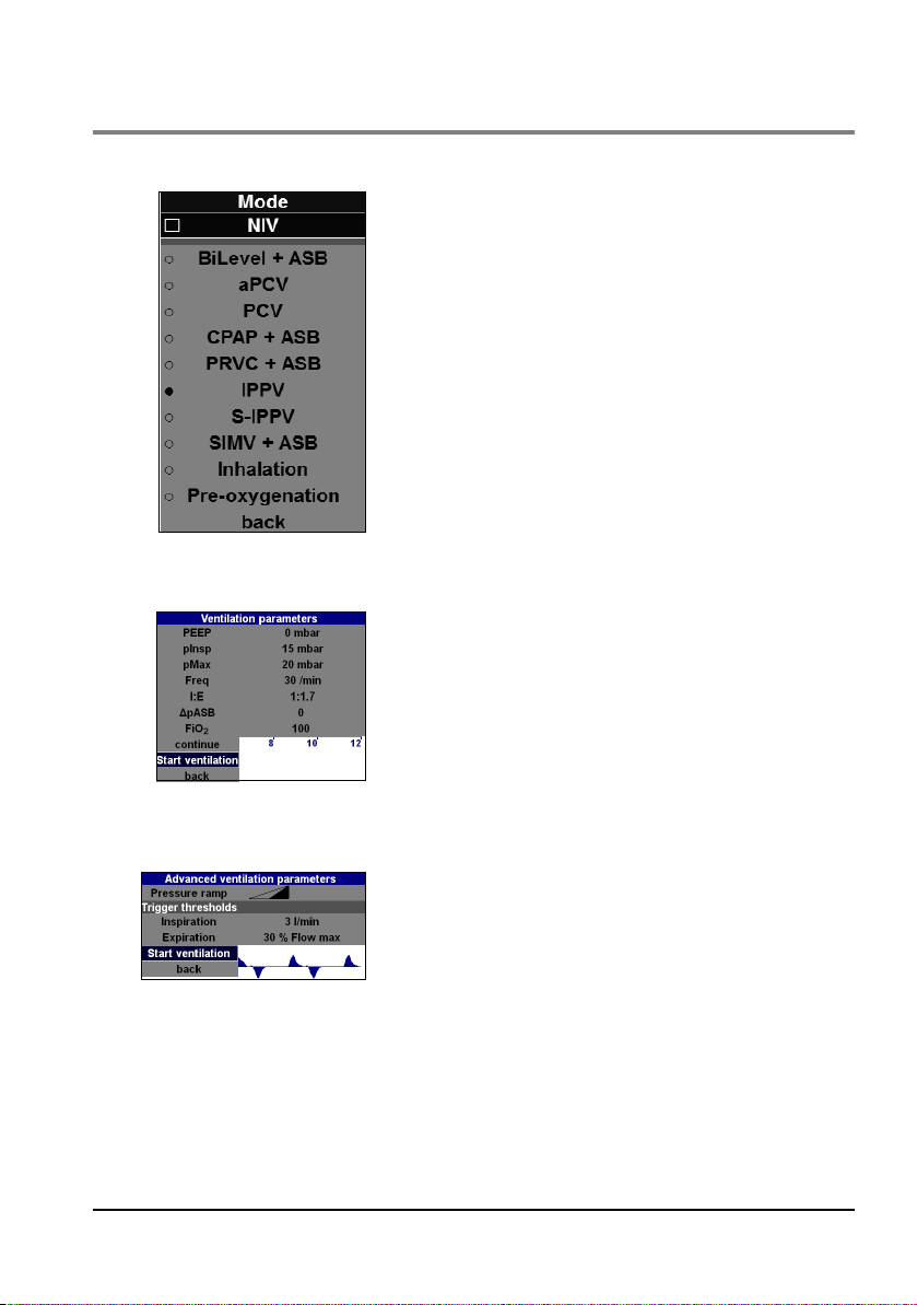
5.6 Changing the ventilation mode
To change the currently set ventilation mode, proceed as follows.
1. First, use the "Mode" function button to select the
"Mode" menu.
2. Then use the navigation knob or the context-dependent function buttons on the right of the display to select whether you wish to ventilate invasively or noninvasively.
The device then proposes the possible ventilation
modes to you. The possible ventilation modes for noninvasive ventilation are: BiLevel + ASB, aPCV, PCV and
CPAP + ASB.
3. Then select the required ventilation mode. Alternatively, you can select the "Inhalation" or "Pre-oxygenation" function.
4. Confirm your selection by pressing the navigation knob
or the corresponding context-dependent function button.
5. Set the ventilation parameters for the selected mode.
6. Then select "continue" to proceed to the "Advanced
ventilation parameters" submenu and confirm your selection.
Continue from point 7.
or
Select "Start ventilation" and confirm your selection.
The ventilation begins in the newly selected ventilation
mode.
7. Set the advanced ventilation parameters for the selected mode.
8. Select "Start ventilation" and confirm your selection.
The ventilation begins in the newly selected ventilation
mode.
If you change from one ventilation mode to another, the unit will respond as follows:
• Ventilation parameters which are also available in the new ventilation
mode are retained unchanged.
• Ventilation parameters which are not available in the new ventilation
mode are saved, but have no influence on current ventilation progress.
48 EN Operation
Page 49

The saved values become available again as soon as the previous
ventilation mode is reactivated.
• When changing from volume-controlled ventilation to pressurecontrolled ventilation, the unit adopts the preset inspiratory pressure
from the operator menu.
• If you have selected a volume-controlled mode, and if the tidal volume
or ventilation rate has changed, the device automatically adapts the
corresponding alarm limits (± 30%) before the ventilation mode is
changed. This automated process does not apply if the parameters are
changed during ventilation without the ventilation mode being changed.
5.7 Selecting additional ventilation functions
The ventilation functions "O2 concentration" and "100% O2" are available for all the
ventilation modes. You can call up and set these functions at any time using the fixedassignment function buttons on the right of the display.
Warning!
Risk of poisoning! Highly concentrated oxygen can have a toxic effect on the patient
if administered for too long, depending on the age of the patient. When ventilating
with pure oxygen or an oxygen-air mixture, make sure that oxygen is only
administered for an appropriate period.
Setting the O2 concentration
To save oxygen, ventilation is normally carried out with an oxygen/air mixture. The
administered oxygen concentration can be selected between 40% and 100%. The
currently measured value is shown in the info field on the display.
If you switch from oxygen/air mixture (40% O
minute volume changes within the preset tolerances (see "14. Technical Data" on
page 142). To set the O
concentration, proceed as follows.
2
1. Use the FiO
menu.
2. Select the required inspiratory O
the navigation knob or the function buttons.
) to pure oxygen (100% O2), the respiratory
2
button to call up the "O2 concentration"
2
concentration using
2
Operation EN 49
Page 50
Notice:
When performing ventilation with a tidal volume
Vt < 200 ml, a PEEP > 0 mbar and an inspiratory O
concentration set to FiO
< 70%, the inspiratory O2
2
concentration administered can deviate from the
set value. Reduce the PEEP to decrease the
administered inspiratory O
concentration.
2
3. Press the button or the navigation knob to confirm
your selection.
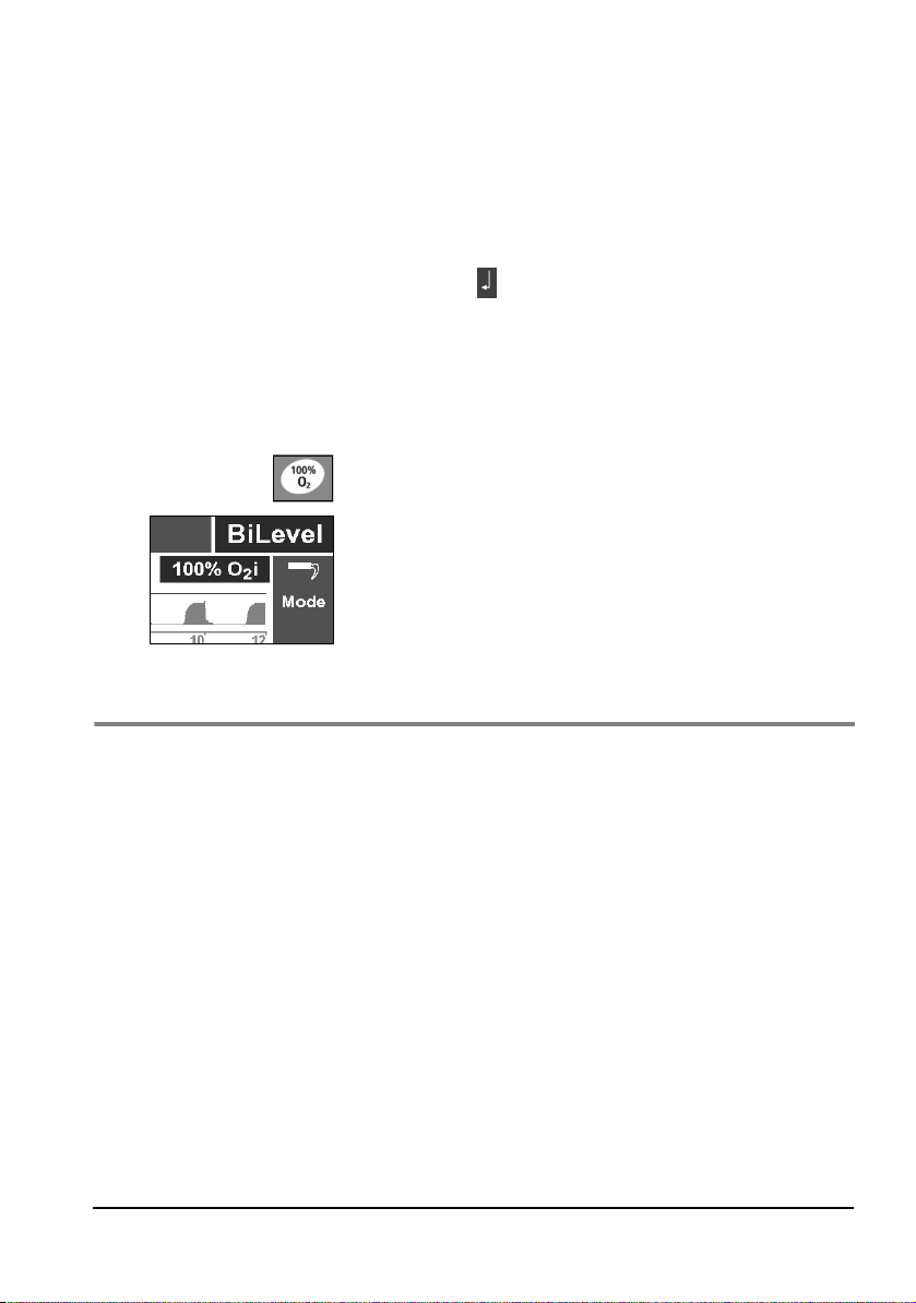
Activate the 100% O2 function
To raise the oxygen concentration to % briefly (two minutes maximum), you can use the
"100% O
" function.
2
1. Press the "100% O
The message "100% O
2. Press the "100% O
" button to activate the function.
2
" appears in the display.
2
" button again to end the function.
2
Ventilation is continued with the originally set O2
concentration. The function is ended automatically
after two minutes.
5.8 Performing ventilation
2
Endotracheal tube
As a rule, the patient is intubated before the tube is connected to the patient valve.
1. Set the desired ventilation mode and the associated ventilation parameters.
2. Attach the patient valve to the endotracheal tube connector.
3. During ventilation, check the respiratory parameters on the display. This will enable you
to determine whether ventilation is adequate.
Notice:
If your unit is equipped with the optional CO
measurement, you can check the tube
2
position on the basis of the capnogram and correct it if necessary.
Ventilation mask
1. If necessary, use the elbow supplied with the hose system to allow you to optimize the
route of the hose system, depending on the patient's position.
50 EN Operation
Page 51

Caution!
Example of ventilation progress before and
after decrease in compliance during volume-controlled
ventilation
Using the elbow increases the dead space of the hose system. Take this into account
when setting the ventilation parameters. Otherwise the success of treatment may be
compromised.
2. Attach the mask to the hose system.
3. If necessary, introduce a Guedel oropharyngeal tube to keep the patient's airways free.
4. Place the ventilation mask over the patient's mouth and nose.
5. Tilt back the patient's head and, at the same time, hold the mask tight against the
patient's face with the C grip.
5.9 Monitoring ventilation
General
During ventilation, you must monitor the patient continuously. You can follow the progress
of ventilation on the display. You can select various display formats.
High airway resistances, e.g., due to obstructions of the airway or during external cardiac
massage, may change the respiratory minute volume, depending on the ventilation mode.
If lung compliance decreases, the unit responds as follows:
• With volume-controlled ventilation, the ventilation pressure rises until
the set pressure limit is reached, while the ventilation volume remains
constant. Then the applied volume drops.
• With pressure-contolled ventilation, the applied volume drops while the
pressure remains constant.
Notice:
All the displayed measurements for flow, volume, or MV relate to ambient
temperature and ambient air pressure.
Operation EN 51
Page 52

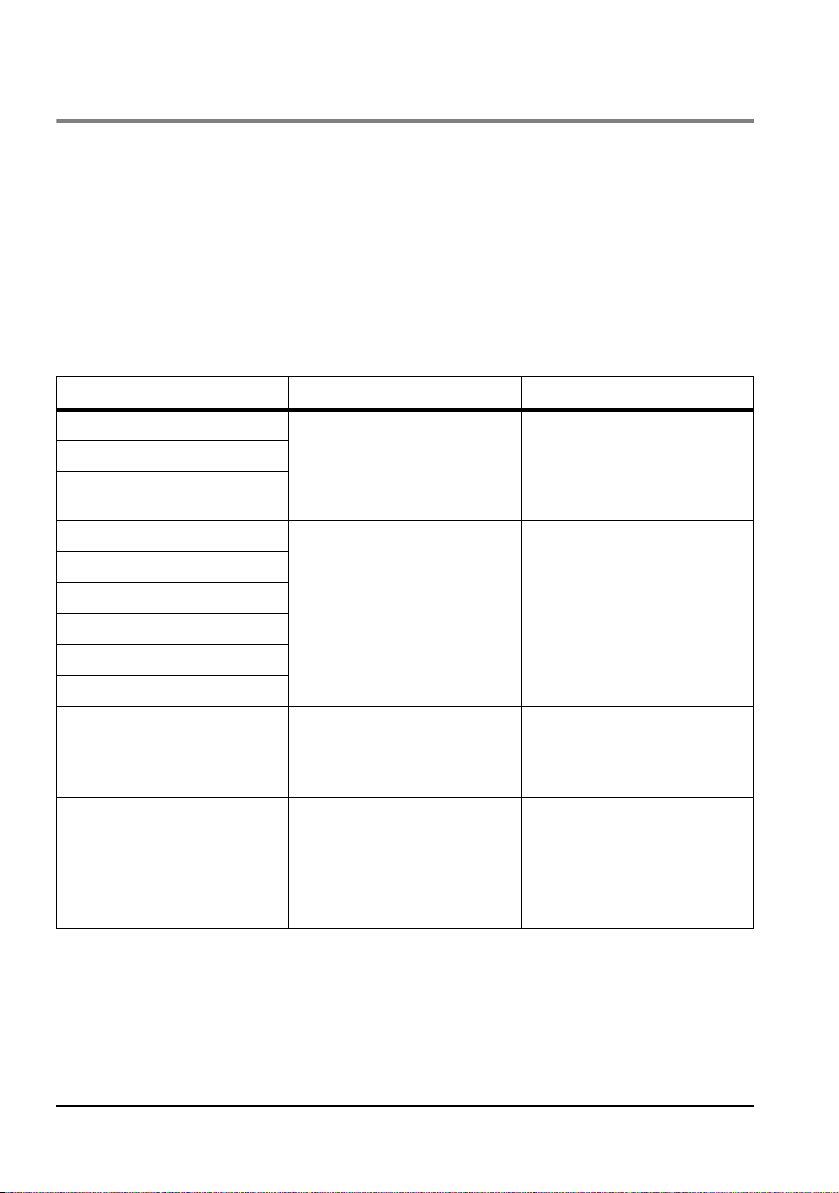
Displayed measurements
During ventilation, the following parameters are displayed
as numbers:
–O
i: inspiratory O2 concentration measured by the
2
unit
: expiratory tidal volume/breath volume
–Vt
e
– f/(fsp): respiratory rate/number of spontaneous
breaths per minute and the corresponding alarm
limit
– MVe: expiratory minute volume and the
corresponding alarm limits
–etCO
: end-tidal CO2 concentration (only with
2
units equipped with optional CO
measurement)
2
and the corresponding alarm limits.
If you deactivate CO2 suction in the Options | CO2
configuration menu, the CO
display is crossed out
2
in red.
If you select two curves and measurements for your curve
display, you will be shown the following measurements in
the display:
– pPeak: Peak pressure in mbar
– pPlat: Plateau pressure in mbar
– pMean: Mean pressure of all measurements in
mbar
– Vleak: Leakage in % Vt
i
Ventilation progress curves
52 EN Operation
For the purpose of monitoring ventilation, the standard
unit displays the following parameters as curves:
– Pressure, flow
– Pressure, flow, measurements
– Pressure gauge (only in volume-controlled modes)
Page 53

If you have a unit equipped with CO2 measurement, you
can vary the display as follows:
– Pressure, flow
–Pressure, CO
– Pressure, flow, CO
– Pressure, flow, measurements
–Pressure, CO
– Gauge (only in volume-controlled modes)
2
2
, measurements
2
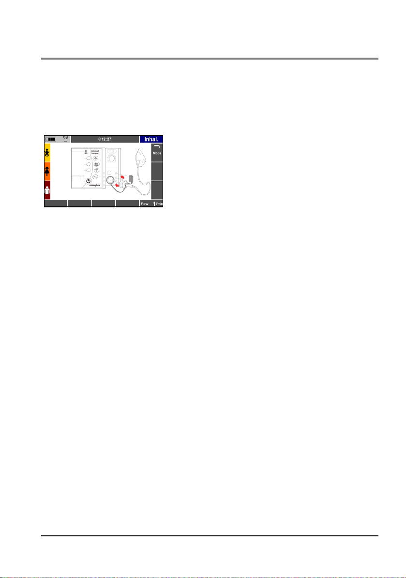
5.10 Performing inhalation
Caution!
The device must not be operated in combination with a nebulizer during oxygen inhalation via an inhalation hose system. Otherwise the device does not generate sufficient pressure for the ventilation and thus inhibits the therapy.
1. Connect the inhalation adapter to the ventilation hose
port on the unit.
or
Connect the inhalation adapter to the patient-side port
of the patient hose system.
2. To block the measuring ports on the device during the
inhalation, place the cover on the inhalation adapter on
the upper two measurement ports on the device.
Notice
The cover is not required when connecting the inhalation adapter to the patient-side port of the patient hose system. In this case, the connection plug
of the measuring hose system blocks the measuring ports instead.
3. Switch on the device.
4. Select "New patient".
Operation EN 53
Page 54

5.11 Alarm signals
5. Select "Adult", "Child", "Infant", or "Height" and
confirm your selection.
The "Mode" submenu opens.
6. Select the "Inhalation" mode and confirm your
selection.
7. Then select "Start ventilation" and confirm your
selection.
The device starts the inhalation.
Alarm priority
MEDUMAT Transport classifies alarms into the following priority levels:
• high priority
• medium priority
• low priority
If two or more alarms occur simultaneously, alarms with the currently highest priority are
displayed cyclically.
You can set limit values for alarms relating to respiratory physiology (see "7.2 Alarm Limits"
on page 85).
54 EN Operation
Page 55
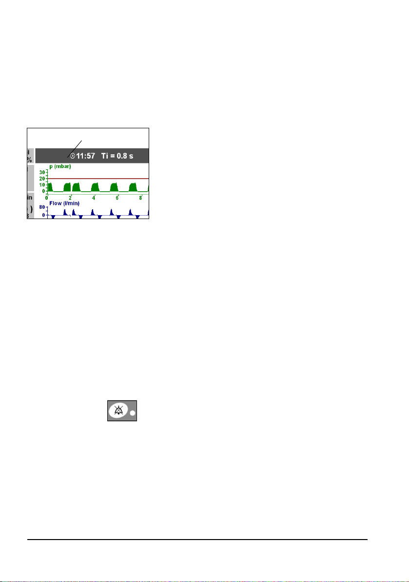
Display of alarms
Info field
MEDUMAT Transport displays alarms as follows:
• High priority
– LED flashes red
– "High priority" alarm sounds every 8 seconds
– Alarm text appears in info field; info field flashes
red
– Corresponding alarm limit in the measurement
field flashes red
• Medium priority
– LED off
– "Medium priority" alarm sounds every 15 seconds
– Alarm text appears in info field; info field flashes
yellow
– Corresponding alarm limit in the measurement
field flashes yellow
• Low priority
– LED off
– "Low priority" alarm sounds every 30 seconds
– Alarm text appears in info field; info field has
turquoise background
Set alarms are displayed in the "Alarm Limits" menu in
their priority color (see "7.2 Alarm Limits" on page 85).
Muting the alarm
You can use the alarm mute button at any time to mute
the alarm signal for 120 s. During this time, the yellow LED
of the alarm mute button flashes. Pressing the button
again reactivates the acoustic alarm. The visual alarm
continues to remain active.
Visual and acoustic alarms are reset automatically as soon
as the cause of the alarm has been removed.
Operation EN 55
Page 56

Notice
• Following the start of ventilation, all alarms are
automatically muted for 120 seconds. This is with
the exception of the technical alarms "Supply
pressure < 2.7 bar", "Battery almost empty", and
"Device malfunction", which cannot be muted.
During this time, visual alarms are still displayed.
• The acoustic alarm output is permanently muted in
NVG mode.
5.12 Ventilation with breathing system filters (not supplied with the unit)
For hygiene purposes, and to condition the air for breathing, you can equip the patient valve
with commercially available filters (HME, bacterial or combined HME/bacterial filters) with
standard 15/22 mm connections. This increases both inspiratory and expiratory resistance.
Therefore you should monitor the ventilation pressure and volume with special care.
Allowance must be made for the larger dead space, especially with children.
Always follow the filter manufacturer's instructions for use.
5.13 Ending ventilation
Caution!
Never empty the oxygen cylinder completely. Always ensure that there is a certain
residual pressure in the cylinder when you return it for filling, since this prevents
moist ambient air from entering and causing corrosion.
1. Check the remaining oxygen content on the contents gauge of the pressure reducer. If
the contents gauge indicates 50 bar or less, the cylinder must be refilled or a reserve
cylinder obtained to ensure that the unit remains ready for use.
2. Close the valve on the oxygen cylinder.
3. Hold down the On/Standby/Off button for 2 seconds to
switch the unit to standby.
Notice:
The unit still uses up electricity in standby mode. If the unit does not need to be used
for a long time or is not connected to the power supply, we recommend switching
it off completely. To do so, hold down the On/Standby/Off button until the LED alarm
goes out (approx. 10 seconds).
56 EN Operation
Page 57

5.14 Calculating the Oxygen level/Operating time
Ventilation operating time (min)
Oxygen supply (l)
Vt x f + O
2
consumption
------------------------------- ---------------------- --------------
100
O
2
concentration
------------------------------ -------------------
×=
Ventilation operating time (min)
1000l
11.3 l/min
--------------------------
100
100%
----------------
× 88 min 1h28min===
Caution!
When calculating the oxygen level in the cylinder, take into account the unit's O
consumption (see "14.5 O
consumption of the unit" on page 149). Otherwise you
2
may miscalculate how long the cylinder will last, which may impair the success of
treatment.
Oxygen level in the cylinder
Oxygen volume = cylinder volume x cylinder pressure
Cylinder volume x Cylinder pressure = Oxygen content
Example 1
Example 2
10 l x 200 bar = 2000 l
10 l x 100 bar = 1000 l
Ventilation operating time
Vt (tidal volume) x f (respiratory rate) = MV (minute volume)
Example 1:
O2 supply = 1000 l; Vt x f = 11 l/min; 100% O2, O2 consumption 0.3 l (see "14.5 O2
consumption of the unit" on page 149).
This gives:
2
If MEDUMAT Transport is operated with an O
time will increase correspondingly.
concentration less than 100%, the operating
2
Operation EN 57
Page 58

5.15 Alternative ventilation
In the event of the MEDUMAT Transport breaking down during ventilation, you have the
following alternatives:
Ventilation bag
1. Pull the patient valve off the tube or mask.
2. Attach the ventilation bag, e.g., COMBIBAG WM 11000 from WEINMANN Emergency
and perform manual ventilation.
Oxygen failure
If the oxygen supply fails or no medical oxygen is available, the MEDUMAT Transport can
also be operated with sterile compressed air or concentrator oxygen (see "Options" on
page 91).
5.16 Changing battery during use
You should change a battery with low capacity in good time. Always keep a fully charged
replacement battery ready for use.
Proceed as follows:
1. Have the fully charged battery ready to hand.
2. Press and hold the On/Standby/Off button until the alarm LED goes out (approx.
10seconds). The device is now switched off.
Caution!
Do not remove the battery whilst the device is in operation, as this prevents the
settings for the last patient being safely stored. Always switch off the device first.
3. Pull the low battery currently in use out of the unit's battery compartment.
4. Insert the replacement battery into the compartment until you hear an audible click.
5. Switch on the device.
6. To adopt the settings entered before changing the battery: Click on "Previous patient"
in the Start menu to call up the settings.
7. Continue with ventilation.
58 EN Operation
Page 59
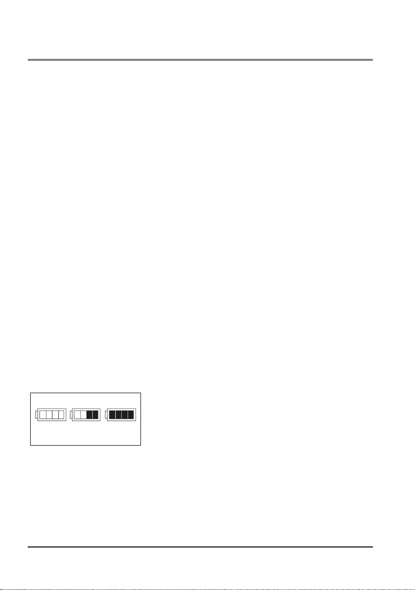
5.17 Battery management
fullhalf full
empty
MEDUMAT Transport has an internal power supply with a rechargeable battery.
Two battery versions are available:
• BATTERY pack Plus WM 28385 for internal and external charging; can be
recharged either in the unit or using an external power supply unit
WM 28937; charge level can be checked on the battery.
• BATTERY pack WM 28384 for internal charging; can only be recharged
in the unit; charge level can be checked on the battery.
For recharging the battery, an external DC power supply with 12 – 15 V (internal charging)
or 15 V (external charging) is required. Use only the vehicle/aircraft on-board electrical
power supply or, if charging from the mains, use power supply unit WM 28937.
MEDUMAT Transport can be operated from an external power supply when the battery is
empty. The battery is charged while the unit is in operation but charging takes longer than
when the unit is switched off.
Caution!
• Never operate the unit without a battery because any voltage dips in the
power supply cannot then be bridged. This would mean that
uninterrupted ventilation of the patient could not be guaranteed.
• Battery-operated medical devices have a limited operating period.
MEDUMAT Transport can normally be operated for 7.5 hours (see "14.1
Specifications" on page 142) without an external power supply,
provided that the battery is fully charged. You should therefore ensure
that the battery is always as fully charged as possible, or that you have a
spare battery ready for use.
Battery charge level indicator (MEDUMAT Transport)
At the top left of the display you will find the symbol
indicating the battery charge level. This is displayed in five
levels. The picture opposite shows examples of a full, halffull and empty battery.
Operation EN 59
Page 60

Charge level indication on the battery itself
Accu-Pack Plus
MEDUMAT Transport
WM 28385
Status LED
Capacity
indicator
Button
When the battery is removed from the unit, you can also
check the charge level on the battery itself. The charge
level is indicated by 4 green LEDs. Press the button on the
battery (see drawings opposite).
Capacity indicator Battery charge level
4 LEDs 100%
3 LEDs 75%
2 LEDs 50%
1 LED 25%
1 LED flashing less than 10 minutes charge left
The battery's charge level is indicated by the status LED
Status LED Battery status
LED glows green Battery fully charged
LED flashes green Battery is being charged
LED glows red Battery faulty. Do not use.
Charging status indicator
The charging status is only indicated when the external power supply is connected, since
only then is it possible to actually charge the battery.
When MEDUMAT Transport is off, the charging status is shown by the charging indicator.
When MEDUMAT Transport is on, the charging status is shown by both the charging
indicator and the capacity indicator.
Key to charging status and capacity indicator:
Battery is being
charged
Battery full
60 EN Operation
Unit off Unit on
Charging
indicator
flashes green flashes green
green green
Charging indicator Capacity indicator
(current charge level)
(full)
Page 61

Unit off Unit on
Charging indicator
Problem during
charging
Battery is being
discharged
Battery missing or
faulty
red red
off off
off red
Charging batteries
MEDUMAT Transport starts charging the battery
conditions are met:
• External power supply with at least 12 V DC is
connected
• The battery is not full (<95% charge)
• Battery temperature not above 45°C or below +5°C
Notice:
The battery WM 28385 has its own charging interface,
so it can also be charged outside the MEDUMAT
Transport. Only use the power supply unit WM 28937.
If charging cannot be started, e.g., because the battery
temperature is outside the permitted range (+ 5°C -
45°C), the charging indicator glows red. It only goes
out once all the conditions for starting charging are
met.
While the battery is being charged, the charging indicator
flashes green.
(current charge level)
(current charge level)
(current charge level)
automatically, as soon as the following
Notice:
If the battery is deeply discharged and you charge it in
the device, the red alarm LED will light up for a short
period of time. It goes out again when the battery
charge level progresses.
Operation EN 61
Page 62

Ending battery charging
MEDUMAT Transport automatically determines the optimum point at which to end
charging by measuring and evaluating the charging curve and battery temperature. As
soon as charging has ended, the charging indicator glows green continuously.
Interrupting battery charging
Battery charging is continuously monitored by MEDUMAT Transport.
Faults which cause charging to be interrupted are:
• Battery temperature rises above 45°C, e.g., due to high ambient
temperature, or falls below +5°C
• Charging current is too high (>3 A) e.g., due to a short-circuit
If one of these problems occurs, charging is automatically interrupted and the charging
indicator glows red.
Charging is also interrupted if there is no external power supply, e.g., because the unit,
which is mounted on a portable system, is removed from the wall mounting. The charging
indicator does not light up in this case because this is not a fault, but a normal operating
situation. As soon as the external power is restored, e.g., when the portable system is put
back into the wall mounting, charging continues immediately.
62 EN Operation
Page 63
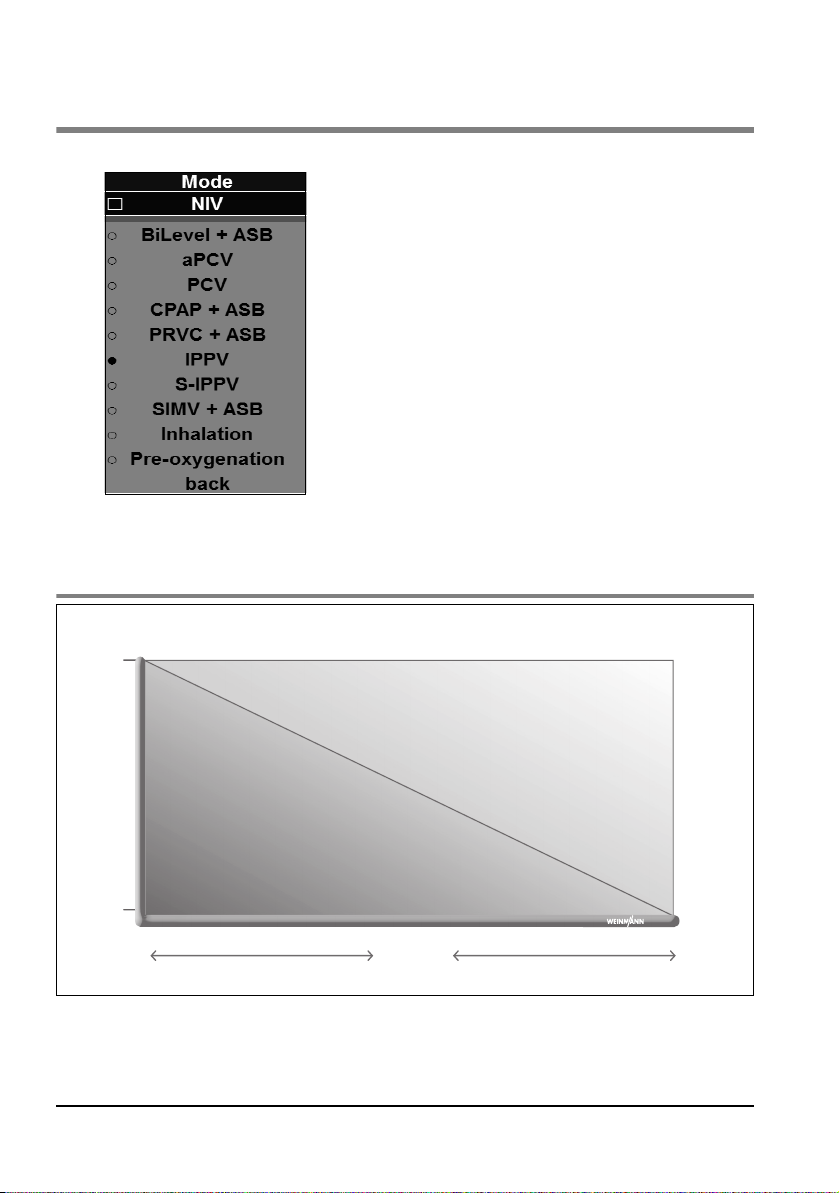
6. Ventilation modes
0%
100%
Breathing effort
Patient
Ventilator
Spontaneous respiration
controlled respiration
assisted
ventilation
You can select different ventilation modes in the "Mode"
menu (see "5.5 Selecting a ventilation mode" on
page 47). This section describes:
• Classification of the ventilation modes (see "6.1
Classification of the ventilation modes" on page 63)
• Important ventilation parameters (see "6.2 Important
ventilation parameters" on page 65)
• Additional functions and safety functions (see "6.3
Additional functions and safety functions" on page 66)
• Pressure-controlled ventilation modes (see "6.4
Pressure-controlled ventilation modes" on page 68)
• Volume-controlled ventilation modes (see "6.5
Volume-controlled ventilation modes" on page 78)
6.1 Classification of the ventilation modes
Ventilation modes EN 63
Page 64
The following ventilation modes are available in the unit:
Control parameter Controlled ventilation Assisted ventilation
Pressure PCV BiLevel + ASB, aPCV CPAP + ASB
Pressure + Volume PRVC + ASB
Volume IPPV
S-IPPV
SIMV + ASB
Spontaneous
respiration
Setting ventilation parameters can cause the classification of the ventilation modes to
change.
The following trigger options are possible in the different ventilations modes:
Trigger time slot
Mode Inspiration trigger Expiration trigger
for mandatory
ASB breath
breaths
BiLevel + ASB yes yes 20% of Te yes
aPCV yes no 0% - 100% of Te no
PCV no no - no
CPAP + ASB yes yes - yes
PRVC + ASB yes yes 20% of Te yes
IPPV no no - no
S-IPPV yes no 100% of Te no
SIMV + ASB yes yes 20% of Te yes
64 EN Ventilation modes
Page 65

6.2 Important ventilation parameters
Ventilation parameter Explanation
Vt Tidal volume (breath volume)
pInsp Inspiration pressure >30 mbar = red light flashes
PEEP
Freq Respiratory rate <5/min = red light flashes
I:E
pMax Maximum inspiratory pressure
Positive end-expiratory
pressure (CPAP)
Ratio of inspiration time to
expiration time
Unit behaviour/
Special features
In certain circumstances it may
no longer be possible to
achieve breath volume with
volume-controlled ventilation.
If airway pressure reaches the
set limit pMax, it will be
limited to the value pMax
(pressure-limited ventilation).
>15 mbar = red light flashes
Inverse ratio = red light flashes
Pressure is limited to this value
by the unit. Can be set from
3 mbar - 65 mbar. pMax is
displayed as a red line in the
pressure curve in all ventilation
modes.
Notice:
Choose values which only cause the red light to flash in the case of special
indications.
Ventilation modes EN 65
Page 66
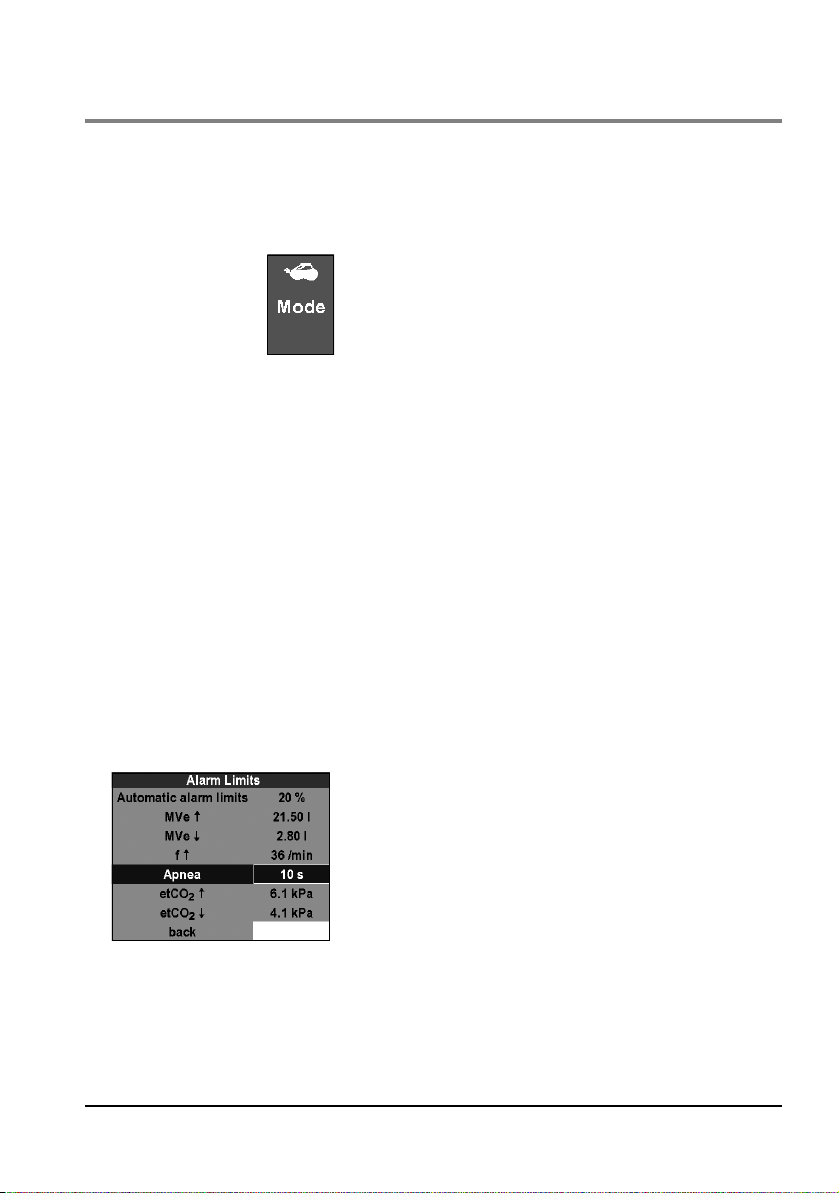
6.3 Additional functions and safety functions
NIV
NIV: Non-Invasive Ventilation (Mask ventilation)
This additional function can also be activated in all
pressure-controlled modes and in the CPAP + ASB
mode.The leakage alarm is deactivated. The unit uses
optimized trigger algorithms for non-invasive ventilation.
If non-invasive ventilation is activated, only the ventilation
modes BiLevel + ASB, aPCV, PCV, and CPAP + ASB
available for this are shown in the "Mode" menu.
If non-invasive ventilation is activated, the symbol for mask
ventilation appears in the "Mode" function indicator.
Caution!
• If the NIV function is not activated during ventilation with leakage, the
patient can only trigger the unit by greatly increasing his/her respiratory
efforts. This may endanger the success of treatment.
• In certain circumstances, the required O
achieved during ventilation with leakage. This is for technical reasons and
does not indicate a malfunction. When the NIV mode is activated, the
alarm limit for "O
20 Vol%.
concentration ↑" is therefore automatically set to
2
concentration may not be
2
Apnea ventilation
66 EN Ventilation modes
Apnea ventilation is a safety function which causes the
unit to take over and continue ventilation if the patient
stops breathing (Apnea). If the patient is no longer
breathing spontaneously and the set Apnea time (see "7.2
Alarm Limits" on page 85) in the "Alarm Limits" menu has
elapsed, the unit will ventilate the patient (mandatorily)
with a preset ventilation mode. A high-priority alarm
sounds and the mode function indicator flashes red.
Apnea ventilation is available in the ventilation modes
BiLevel + ASB, aPCV, CPAP + ASB, PRVC + ASB, S-IPPV,
and SIMV + ASB.
Page 67
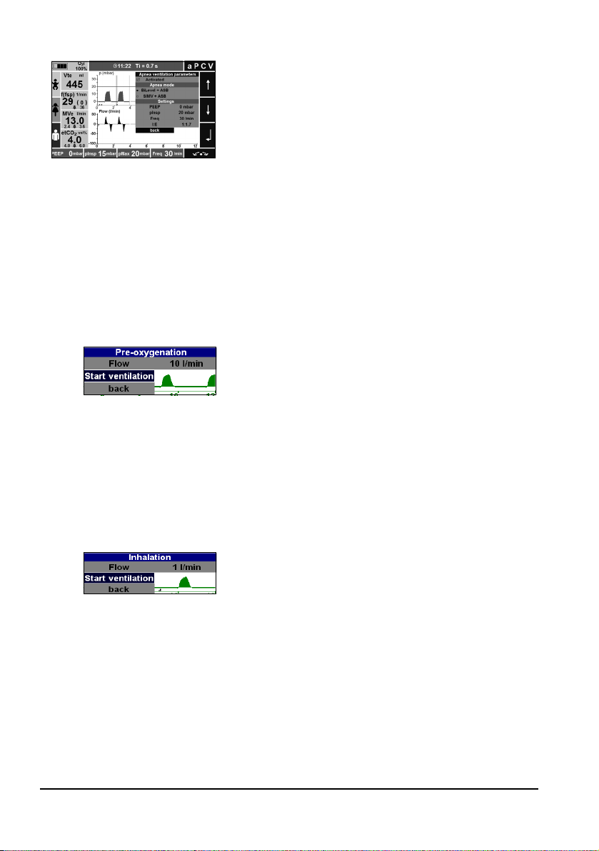
Pre-oxygenation
Inhalation
You can activate or deactivate apnea ventilation in the
"Apnea ventilation parameters" menu. The "Apnea
mode" menu item allows you to select which ventilation
mode the unit utilizes during apnea ventilation:
• BiLevel + ASB (pressure-controlled)
• SIMV + ASB (volume-controlled)
In this menu, you can also set the ventilation parameters for
Apnea ventilation. If you do not set any ventilation parameters,
the unit adopts the presettings for these ventilation modes
according to the patient (Infant, child, adult).
Pre-oxygenation is a function which enables the oxygen
content in a patient's lungs to be increased quickly, e.g., in
preparation for intubation.
The device administers a flow of 10-25 l/min with 100%
O
, which can be set in the menu item "Pre-oxygenation".
2
Pressure is limited to 10 mbar for safety reasons.
You can select pre-oxygenation in the "Mode" menu (see
"6. Ventilation modes" on page 63). To deactivate pre-oxygenation, switch to another ventilation mode.
Inhalation is a function which makes it possible to increase
the oxygen content in a patient's lungs. The inhalation
flow can be set at a value between 0 l/min and 10 l/min.
The unit administers a flow of 100% O
in the menu item "Inhalation".
You can select inhalation in the "Mode" menu (see "6.
Ventilation modes" on page 63).
which can be set
2
Caution!
In the case of oxygen inhalation, check that the inhalation
hose is connected and the measuring ports on the
MEDUMAT Transport are blocked (see "4.3 Connecting
the inhalation adapter" on page 34).
Ventilation modes EN 67
Page 68
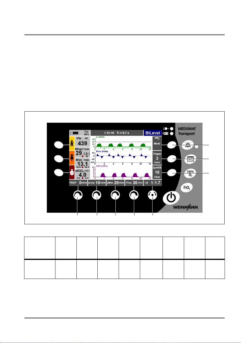
6.4 Pressure-controlled ventilation modes
8
7
21345
6
Caution!
Ventilation pressure is limited to pMax in the pressure-controlled modes
(pressure limitation). A high-priority alarm is triggered when this pressure limit is
reached.
BiLevel + ASB
BiLevel: ventilation at two pressure levels
ASB: Assisted Spontaneous Breathing
You can set the following ventilation values using the control knobs:
Ventilation
mode
BILEVEL +
ASB
You can find more setting options under the menu item "Advanced ventilation
parameters" in the main menu (see "7.4 Advanced ventilation parameters" on page 87).
Control
knob
PEEP pInsp pMax Freq.
1
Control
knob 2
Control
knob 3
Control
knob 4
Navigation
knob 5
I:E and
Select/
Confirm
Function
button 6
Δ pASB Trigger Mode
Function
button 7
Function
button
68 EN Ventilation modes
8
Page 69
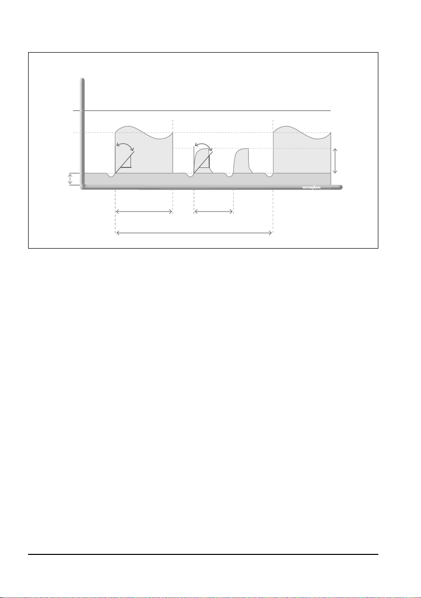
The BiLevel + ASB mode is used for pressure-controlled ventilation combined with free
dP
dT
Pressure
Time
TI=T
insp
Δ pASB
assisted respirationautomated ventilation
1/Freq.
(spontaneous)
1/Freq. (set)
pMax
pInsp
PEEP
Pressure
ramp
dP
dT
spontaneous respiration at pressure levels pInsp and PEEP during the entire breathing cycle
and for adjustable pressure support at PEEP level.
This mode is used on patients who have no spontaneous respiration or on spontaneously
breathing patients. The BiLevel + ASB ventilation mode is also used as the mode for Apnea
ventilation (see "Apnea ventilation" on page 66).
The patient can trigger a mandatory, pressure-controlled mechanical breath during a
predetermined trigger time slot. The trigger time slot is 20% of the expiration time T
before the anticipated mandatory mechanical breath. For the rest of the time, the patient
can breathe spontaneously or with the aid of pressure support (see "CPAP + ASB" on
page 74).
Tidal volume and minute volume are determined by the set pInsp, lung compliance and the
set inspiration time T
.
i
e
Ventilation modes EN 69
Page 70
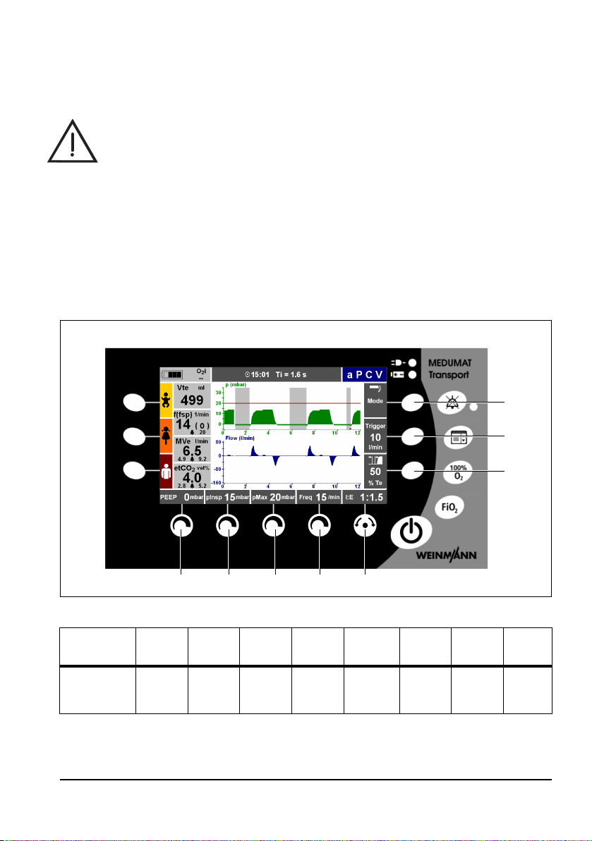
aPCV
8
7
21345
6
aPCV: assisted Pressure Controlled Ventilation
Warning!
• Risk of hyperventilation! Continuously monitor the patient's measured
respiratory rate and measured minute volume in order to prevent
hyperventilation. To this end, set a narrow alarm limit for the
to recognize the risk of hyperventilation in good time.
• Risk of air trapping! Continuously monitor the airway pressure in order to
prevent air trapping.
• Risk of intrinsic PEEP! An expiration that is too short can cause the pressure to
increase slowly at the end of the expiration. Monitor the sensitivity of the
inspiratory trigger. If the set PEEP is exceeded, a high-priority alarm (PEEP
guarantees the safety of the patient.
f ↑ alarm, in order
↑)
You can set the following ventilation values using the control knobs:
Ventilation
mode
aPCV
Control
knob 1
PEEP pInsp pMax Freq.
Control
knob 2
Control
knob 3
Control
knob 4
Navigation
knob 5
I:E and
Select/
Confirm
Function
button 6
Trigger
time slot
70 EN Ventilation modes
Function
button 7
Trigger Mode
Function
button 8
Page 71
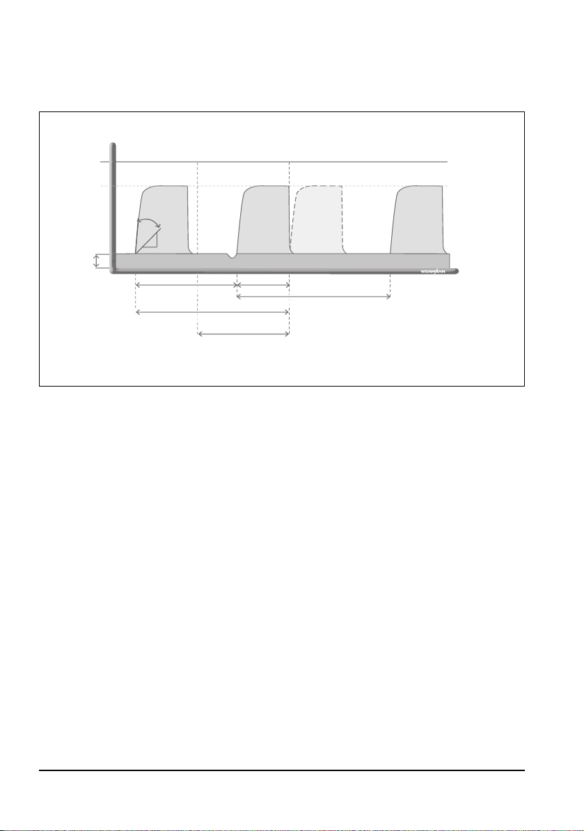
You can find more setting options under the menu item "Advanced ventilation parame-
Pressure
Time
pMax
Synchronized time slot
(adjustable)
PEEP
dP
dT
Pressure
ramp
pInsp
Automated
ventilation
Synchronized
automated
ventilation
Automated
ventilation
1/Freq. (current) ΔT
1/Freq. (set)
1/Freq. (set)
ters" in the "Main menu" (see "7.4 Advanced ventilation parameters" on page 87).
The aPVC mode is used for pressure-controlled, assisted ventilation at a fixed mandatory
ventilation rate.
In case of spontaneous respiration, the patient has the possibility of increasing the rate and
consequently the minute volume MV. If the patient displays a spontaneous respiratory effort within a specified time slot of the expiration, the mandatory mechanical breath is synchronized with the patient's respiration. The time slot or trigger time slot can be set in %
of Te before the next expected mandatory mechanical breath. If the patient displays a
spontaneous respiratory effort outside of the set trigger time slot, no mandatory mechanical breath is triggered.
Ventilation modes EN 71
Page 72
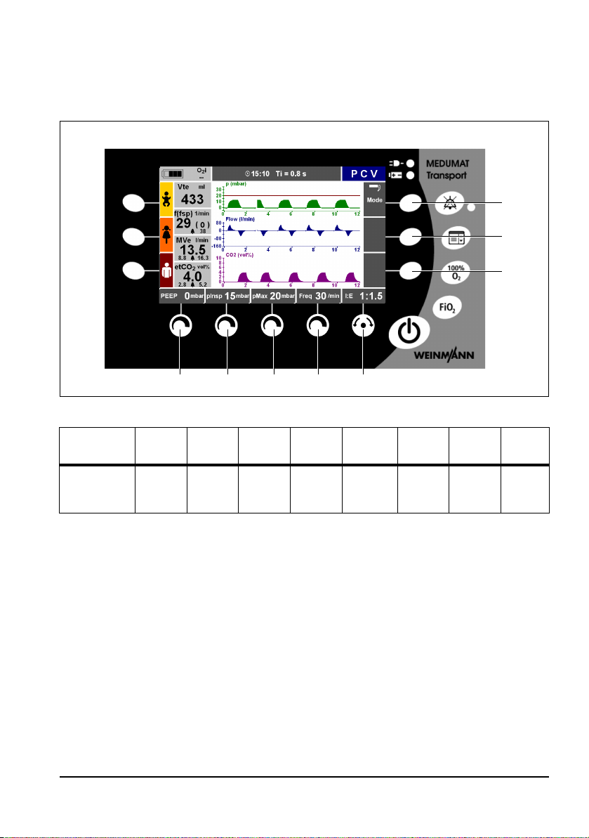
PCV
8
7
21345
6
PCV: Pressure Controlled Ventilation
You can set the following ventilation values using the control knobs:
Ventilation
mode
PCV
Control
knob
PEEP pInsp pMax Freq.
1
Control
knob 2
Control
knob 3
Control
knob 4
Navigation
knob 5
I:E and
Select/
Confirm
Function
button 6
--Mode
Function
button 7
Function
button 8
You can find more setting options under the menu item "Advanced ventilation
parameters" in the main menu (see "7.4 Advanced ventilation parameters" on page 87).
72 EN Ventilation modes
Page 73

Pressure
Time
pMax
1/Freq. (set)
PEEP
1/Freq. (set)
dP
dT
Pressure
ramp
pInsp
PCV mode is used for mandatory pressure-controlled ventilation with fixed pressure levels.
This mode is used on patients who have no spontaneous respiration. However, a
spontaneously breathing patient can breathe deeply and freely during expiration.
The set maximum pressure limitation (pMax) ensures the safety of the patient.
Ventilation modes EN 73
Page 74
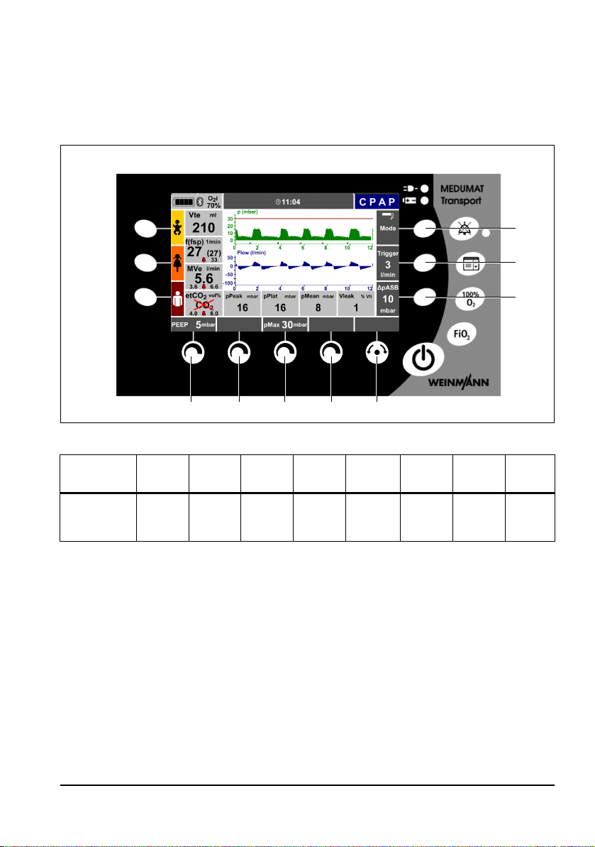
CPAP + ASB
8
7
21345
6
CPAP: Continuous Positive Airway Pressure
ASB: Assisted Spontaneous Breathing
You can set the following ventilation values using the control knobs:
Ventilation
mode
CPAP + ASB
Control
knob
PEEP - pMax -
1
Control
knob 2
Control
knob 3
Control
knob 4
Navigation
knob 5
Select/
Confirm
only
Function
button 6
Δ pASB Trigger Mode
Function
button 7
Function
button 8
You can find more setting options under the menu item "Advanced ventilation
parameters" in the main menu (see "7.4 Advanced ventilation parameters" on page 87).
74 EN Ventilation modes
Page 75
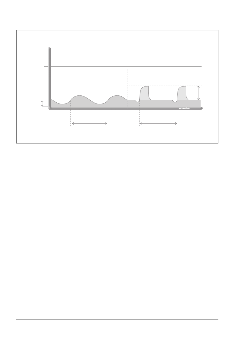
Pressure
Time
1/Freq. (spontaneous) 1/Freq. (spontaneous)
pMax
CPAP / PEEP
CPAP without pressure support CPAP with pressure support ASB
ΔpASB
The CPAP + ASB mode can be separated into its individual elements:
The set value CPAP/PEEP is used to increase the pressure level of respiration in order to raise
the functional residual capacity (FRC) of a spontaneously breathing patient.
The ASB mode is used for pressure support of insufficient or exhausted spontaneous
respiration. The patient is able to breathe spontaneously without any restriction, but is
supported in his breathing effort by MEDUMAT Transport.
The CPAP + ASB mode is used exclusively on patients with adequate spontaneous
respiration.
In principle, the pressure is set at the end of expiration (PEEP). In addition, pressure support
(
Δ pASB) can be switched on if needed. Ventilation can be individually adjusted to suit the
patient with the aid of the inspiratory and expiratory triggers. The inspiratory trigger
indicates a sensitivity for triggering pressure support. The expiratory trigger determines
when the unit should switch off pressure support, which enables the administered volume
and the inspiration time to be set indirectly.
The set maximum pressure limitation (pMax) ensures the safety of the patient.
Ventilation modes EN 75
Page 76

PRVC + ASB
8
7
21345
6
PRVC: Pressure Regulated Volume Controlled Ventilation
ASB: Assisted Spontaneous Breathing
You can set the following ventilation values using the control knobs:
Ventilation
mode
PRVC + ASB
Control
knob
PEEP Vt pMax Freq.
1
Control
knob 2
Control
knob 3
Control
knob 4
Navigation
knob 5
I:E and
Select/
Confirm
Function
button 6
Δ pASB Trigger Mode
Function
button 7
Function
button 8
You can find more setting options under the menu item "Advanced ventilation
parameters" in the main menu (see "7.4 Advanced ventilation parameters" on page 87).
76 EN Ventilation modes
Page 77
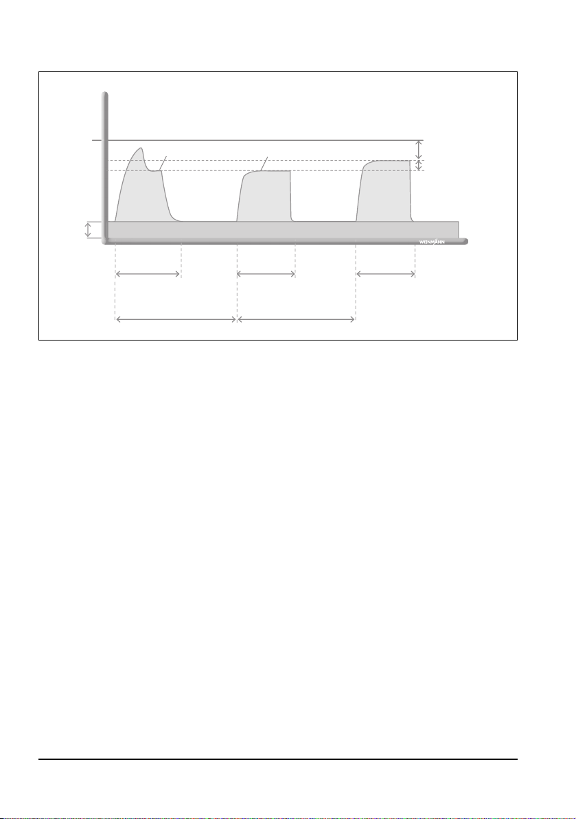
Pressure
Time
pMax
1/Freq. (set) 1/Freq. (set)
volume-controlled
mechanical breath
pressure-controlled
mechanical breath
Safety
margin 5 mbar
Increments
max. 3 mbar
pPlat
pInsp (variable)
PEEP
pressure-controlled
mechanical breath
The controlled ventilation mode PRVC + ASB combines the advantages of both pressurecontrolled ventilation and volume-controlled ventilation. The set tidal volume is applied
with the minimum ventilation pressure possible.
Ventilation begins with three volume-controlled breaths with the set tidal volume and
decreasing flow. The volume-controlled breaths have a plateau time of 50% of the
configured inspiration time T
. The unit selects the measured plateau pressure as starting
i
value for the inspiratory pressure pInsp of the following pressure-controlled ventilation. It
measures the administered volumes and adjusts the ventilation pressure accordingly. If the
lung parameters change during ventilation, the unit alters the inspiratory pressure pInsp in
increments of a maximum of 3 mbar in order to achieve the set tidal volume again and
thereby automatically compensate for changes in the patient.
Measuring the applied volume is improved by compensating hose compliance. This enables
precise control of the required tidal volume, in particular of small tidal volumes under high
airway pressures.
The set maximum pressure limitation (pMax) ensures the safety of the patient. For safety
reasons inspiratory pressure pInsp
(pMax). Once maximum ventilation pressure (pMax - 5 mbar) is achieved, the unit
administers as much volume as possible. If this volume deviates from the set tidal volume,
is 5 mbar below the set maximum pressure limitation
the unit triggers the low-priority alarm "Vt not achievable".
Ventilation modes EN 77
Page 78
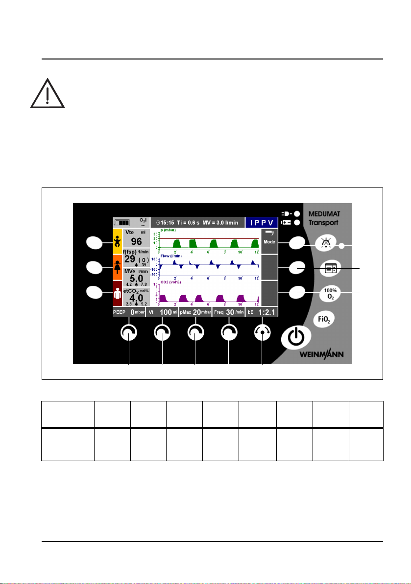
6.5 Volume-controlled ventilation modes
8
7
21345
6
Warning!
Risk of inconsistent volume once pressure limitation pMax
patient continuously throughout volume-controlled ventilation modes and change
the setting parameters if necessary. Once the pressure limitation is reached, a highpriority alarm (airway pressure
↑) guarantees the safety of the patient.
IPPV
IPPV: Intermittent Positive Pressure Ventilation
is reached! Monitor the
You can set the following ventilation values using the control knobs:
Ventilation
mode
IPPV
You can find more setting options under the menu item "Advanced ventilation
parameters" in the main menu (see "7.4 Advanced ventilation parameters" on page 87).
Control
knob
PEEP Vt pMax Freq.
1
Control
knob 2
Control
knob 3
Control
knob 4
Navigation
knob 5
I:E and
Select/
Confirm
Function
button 6
--Mode
Function
button 7
Function
button 8
78 EN Ventilation modes
Page 79
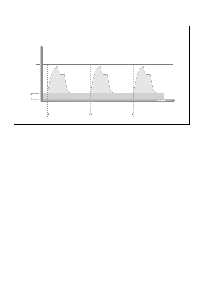
The IPPV mode is used for mandatory volume-controlled ventilation with a fixed tidal
Pressure
Time
pMax
1/Freq. (set)
automated ventilation automated ventilation
PEEP
1/Freq. (set)
pPlat
volume. This mode is used on patients who have no spontaneous respiration. However, a
spontaneously breathing patient can breathe deeply and freely during expiration.
The set maximum pressure limitation (pMax) ensures the safety of the patient.
Ventilation modes EN 79
Page 80

S-IPPV
8
7
21345
6
S-IPPV: Synchronized Intermittent Positive Pressure Ventilation
Warning!
• Risk of hyperventilation! Continuously monitor the patient's measured
respiratory rate and measured minute volume in order to prevent
hyperventilation. To this end, set a narrow alarm limit for the
to recognize the risk of hyperventilation in good time.
• Risk of air trapping! Continuously monitor the airway pressure in order to
prevent air trapping.
• Risk of intrinsic PEEP! An expiration that is too short can cause the pressure to
increase slowly at the end of the expiration. Monitor the sensitivity of the
inspiratory trigger. Once the set PEEP is exceeded, a high-priority alarm (
guarantees the safety of the patient.
f ↑ alarm, in order
PEEP ↑)
You can set the following ventilation values using the control knobs:
Ventilation
mode
S-IPPV
Control
knob 1
PEEP Vt pMax Freq.
Control
knob 2
Control
knob 3
Control
knob 4
Navigation
knob 5
I:E and
Select/
Confirm
Function
button 6
- Trigger Mode
80 EN Ventilation modes
Function
button 7
Function
button 8
Page 81
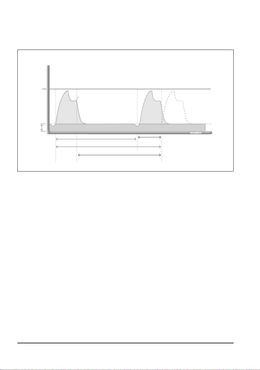
You can find more setting options under the menu item "Advanced ventilation
Pressure
Time
pMax
1/Freq. (set)
automated ventilation
synchronized automated
ventilation
1/Freq. (current)
Synchronized time slot
ΔT
pPlat
PEEP
parameters" in the main menu (see "7.4 Advanced ventilation parameters" on page 87).
The S-IPPV mode is used for volume-controlled ventilation with a variable mandatory
minute volume MV. Throughout the entire expiratory phase, a trigger is active which
enables the patient to trigger a new breath. This means the patient has the option of
increasing the respiratory rate and therefore the minute volume MV, and adapting these
to his/her needs. As a rule this mode is used on patients who have inadequate spontaneous
respiration.
Ventilation in the S-IPPV mode corresponds to ventilation in the IPPV mode with the
difference that it is possible to synchronize ventilation with the patient's efforts to inhale.
Since the setting for the respiratory rate is lower, the patient can trigger mandatory
mechanical breaths spontaneously. A trigger time slot extending throughout the expiration
time is available for this synchronization.
Ventilation modes EN 81
Page 82

SIMV + ASB
8
7
21345
6
SIMV: Synchronized Intermittent Mandatory Ventilation
ASB: Assisted Spontaneous Breathing
You can set the following ventilation values using the control knobs:
Ventilation
mode
SIMV + ASB
Control
knob
PEEP Vt pMax Freq.
1
Control
knob 2
Control
knob 3
Control
knob 4
Navigation
knob 5
I:E and
Select/
Confirm
Function
button 6
Δ pASB Trigger Mode
Function
button 7
Function
button 8
You can find more setting options under the menu item "Advanced ventilation
parameters" in the main menu (see "7.4 Advanced ventilation parameters" on page 87).
82 EN Ventilation modes
Page 83
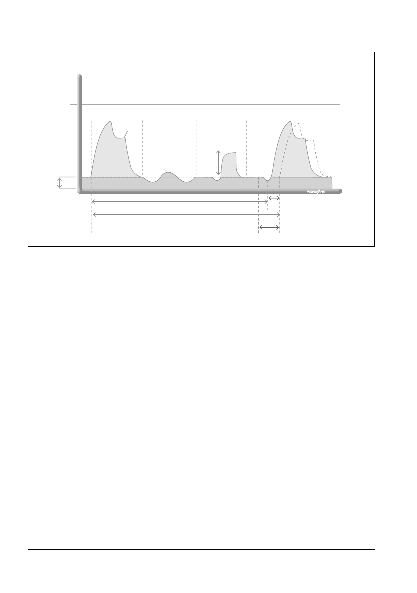
The SIMV + ASB mode is used for volume-controlled ventilation with a fixed mandatory
Pressure
Time
pMax
1/Freq. (set)
automated ventilation synchronized automated
ventilation
1/Freq. (current)
Synchronized time slot
ΔT
spontaneous
respiration
assisted
spontaneous
respiration
pPlat
ΔpASB
PEEP
minute volume MV.
The patient can breathe spontaneously between the mandatory mechanical breaths and
thereby increase the minute volume.
During spontaneous respiration, the mandatory mechanical breath is synchronized with
the patient's breathing. The mandatory minute volume and the mandatory respiration rate
remain unchanged.
The set maximum pressure limitation (pMax) ensures the safety of the patient.
The SIMV + ASB ventilation mode is also used as the mode for Apnea ventilation
(see "Apnea ventilation" on page 66).
The patient can trigger a mandatory, pressure-controlled mechanical breath during a
predetermined trigger time slot. The trigger time slot is available in the final 20% of
expiration time T
the aid of pressure support (see "CPAP + ASB" on page 74).
. For the rest of the time, the patient can breathe spontaneously or with
e
Ventilation modes EN 83
Page 84

7. Main menu
In the main menu, you can optimize the unit's settings to
suit the particular operating conditions. The main menu
can be called up at any time using the "Main menu"
function button.
To navigate in the menu, you can use either the navigation
knob or the context-dependent function buttons on the
right of the display (see "5.1 Controls" on page 38).
7.1 Activating automatic alarm limits
General
When the "Activate automatic alarm limits" function is
activated, the unit automatically determines limits for the
alarms relating to respiratory physiology. Alternatively, you
can activate the automatic alarm limits by keeping the
alarm mute button depressed (approx. 2 seconds).
Crucial for determining the limits are the respiratory values
measured at the moment when the function is activated
(Vt
, MVe, f, if necessary etCO2).
e
In the "Alarm Limits" menu (see "7.2 Alarm Limits" on
page 85), you can set the amount of deviation (in %) from
the current respiratory value, which should trigger an
alarm.
84 EN Main menu
Notice:
This overwrites the values set in "Alarm Limits" (see
"7.2 Alarm Limits" on page 85).
Page 85

Automatic alarm calculation for the Apnea alarm
Depending on the set percentage, the Apnea alarm is set to 4 (10%), 5 (20%) or 6 (30%)
respiratory periods. The length of a respiratory period is 60/f in seconds, i.e., with a
measured respiratory rate of, for example, 15/min, the increments for the Apnea alarm
limit are 16 s, 20 s, and 24 s.
7.2 Alarm Limits
You can set limit values for alarms relating to respiratory
physiology. Once the limit values are reached, the unit
triggers an alarm.
You can set the following:
Alarm Setting range
10%, 15%, 20%, 25% or 30%
deviation from the respiratory
Automatic alarm
limits
MVe ↑ 1 l - 160 l
MVe ↓ 0.1 l - 110 l
f ↑ 1/min - 150/min
Apnea 4 s - 60 s
Only for units equipped with CO
↑
etCO
2
etCO
↓
2
values at the moment of
activation.
The automatic alarm limits are
set to ± 30% on delivery.
measurement:
2
20 mmHg - 75 mmHg
2.6 Vol% - 9.9 Vol%
2.6 kPa - 10 kPa
0 mmHg - 40 mmHg
0 Vol% - 5.3 Vol%
0kPa - 5.4kPa
If the unit triggers a set alarm, the alarm in this menu is
displayed in the color of its priority (see "5.11 Alarm
signals" on page 54).
The alarm limit for the CO
i↑ alarm is set at 5 mmHg.
2
You can also activate the alarm limits menu by keeping the
alarm mute button depressed (approx. 2 seconds).
Main menu EN 85
Page 86
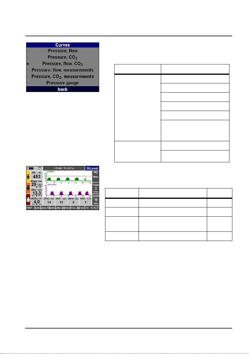
7.3 Curves
In this menu, you can vary the display for monitoring
ventilation.
You can make the following settings:
Parameters Setting range
Pressure, flow
Curves
(Units equipped with
CO
measurement)
2
Curves
(Units without CO
measurement)
2
Pressure, CO
Pressure, flow, CO
Pressure, flow, measurements
Pressure, CO
Pressure gauge
(only available in volumecontrolled modes)
Pressure, flow
Pressure, flow, measurements
2
2
, measurements
2
If you select a display with measurements, the following
measurements will be displayed:
Measurement Explanation Unit
pPeak Peak pressure mbar
pPlat Plateau pressure mbar
pMean
V
leak
Mean pressure of all
measurements
Leakage % Vt
mbar
i
86 EN Main menu
Page 87

7.4 Advanced ventilation parameters
To achieve optimum results during transport ventilation,
you can configure settings in the "Advanced ventilation
parameters" menu, depending on the particular mode
selected.
The non-selectable functions in a particular ventilation
mode are not shown.
Pressure ramp
With this function you can set how quickly the inspiratory
ventilation pressure should be reached.
You can make the following settings:
Parameters Setting range
Flat ramp slow pressure rise
Medium ramp medium pressure rise
Steep ramp fast pressure rise
Notice:
How quickly the set pressure is actually reached
depends on the patient, any possible leakage (NIV) and
the set ventilation parameters.
Flow ramp
With this function you can set how fast the inspiratory
flow should be reached.
You can make the following settings:
Parameters Setting range
Flat ramp slow flow rise
Medium ramp medium flow rise
Steep ramp fast flow rise
Main menu EN 87
Page 88

Flow progress
Trigger thresholds
Notice:
How quickly the set flow is actually reached depends on
the patient, any leakage (NIV) and on the set ventilation
parameters.
With this function you can set the flow progress.
You can make the following settings:
Parameters Setting range
decreasing
Flow progress
constant
Plateau time (0% T
- 50%Ti)
i
If you select a plateau time (see "Plateau time" on
page 154) for the flow progress, for the duration of the
plateau time, no gas will be administered to the patient
and at the same time expiration will be prevented.
With this function you can set the inspiratory and
expiratory trigger threshold and the trigger time slot.
You can make the following settings:
Parameters Setting range
Inspiration 1 l/min - 15 l/min
Expiration 5% Flow max - 50% Flow max
Trigger time slot 0% Te - 100% Te
88 EN Main menu
The "Trigger time slot" function (only available in the
aPCV ventilation mode) can be used to set in which phase
of the expiration the patient can trigger a mandatory
mechanical breath. The setting can be performed in 100%
of the expiration time before the next mechanical breath.
If you set the trigger time slot to 0% Te, the patient has no
possibility of triggering a mandatory mechanical breath
and the ventilation could be viewed as purely controlled
Page 89
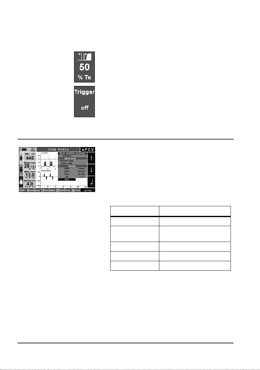
ventilation. In contrast, at a setting of 100% Te, the
patient has the possibility of triggering a mechanical
breath at any point in the whole expiration time.
Alternatively, you can also set the trigger time slot on the
right in the display, using the trigger time slot function key.
Alternatively, you can also set the trigger thresholds on the
right in the display, using the trigger thresholds function
button. Use the control knob to navigate straight to the
"Trigger thresholds" menu item.
7.5 Apnea ventilation parameters
In this menu you can both specify the presettings for the
Apnea ventilation (see "Apnea ventilation" on page 66)
and activate Apnea ventilation. You can select the
following ventilation modes for Apnea ventilation:
• BiLevel + ASB
• SIMV + ASB
You can make the following settings:
Parameters Setting range
PEEP 0 mbar - 30 mbar
pInsp (BiLevel + ASB
only)
Vt (SIMV + ASB only) 50 ml - 2000 ml
Freq 1/min - 60/min
I:E 1:4.0 - 4.0:1
3 mbar - 60 mbar
Main menu EN 89
Page 90
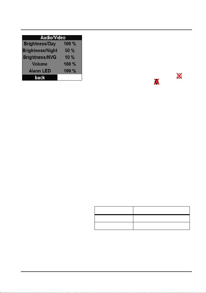
7.6 Audio/Video
This menu can be used to set the display brightness, alarm
volume, and alarm LED:
• Display brightness: Here you can set the display brightness for day colors, night colors, and in NVG mode separately.
• Alarm volume: Here you can set the volume of all the
alarms. If the alarm volume is set to <50%, the symbol appears in the display and the symbol in the
measurement fields. It is only possible to set the alarm
volume to <50% if the menu item Allow 0% audio vol-
ume has been activated in the operator menu (see "8.6
User Settings" on page 105).
Notice:
If you set the alarm volume to <50%, the device’s alarm
function no longer complies with the EN 60601-1-8
and EN 794-3/EN 10651-3 standards.
• Alarm LED: You can activate or permanently deactivate
the alarm LED here. The alarm LED can only be activated/deactivated if the menu item Allow alarm LED off
has been activated in the operator menu (see "8.6 User
Settings" on page 105).
90 EN Main menu
Notice:
If you deactivate the alarm LED, the device’s alarm function no longer complies with the EN 60601-1-8 and
EN 794-3/EN 10651-3 standards.
You can make the following settings:
Parameters Setting range
Brightness/Day 10% - 100%
Brightness/Night 10% - 100%
Page 91
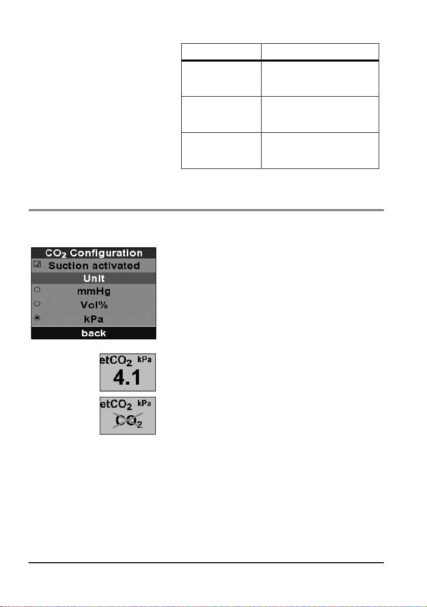
7.7 Options
CO2 configuration
Parameters Setting range
Brightness/NVG (only
when NVG option is
enabled)
Volume
Alarm LED (only
when NVG option is
enabled)
10%-100%
50%-100%
0%-100% (only when NVG
option is enabled)
0%
100%
In this menu, you can activate CO2 suction. You can only
access this menu if you have a unit equipped with CO
2
measurement.
If you activate CO
CO
concentration is shown bottom left in the display.
2
If you deactivate CO
suction, the current end-expiratory
2
suction, this is shown bottom left in
2
the display.
If the device is not equipped with CO
measuring, the
2
measurement field remains empty.
Main menu EN 91
Page 92

Date, time
In the menu, you can select which unit of measurement
the CO2 concentration should be displayed in.
You can make the following settings:
Parameters Setting range
mmHG
Unit
Vol%
kPa
In this menu, you can set the current date and time.
You can make the following settings:
Parameters Setting range
Year
Month
Date, time
Day
Hour
Minute
Notice:
The date and time are also used for the unit's internal
operations. Therefore they should both be checked
regularly and corrected if necessary.
Device data
92 EN Main menu
In this menu you can see the software version of your
device (with date) and the date and time of the most
recent function check passed.
Page 93
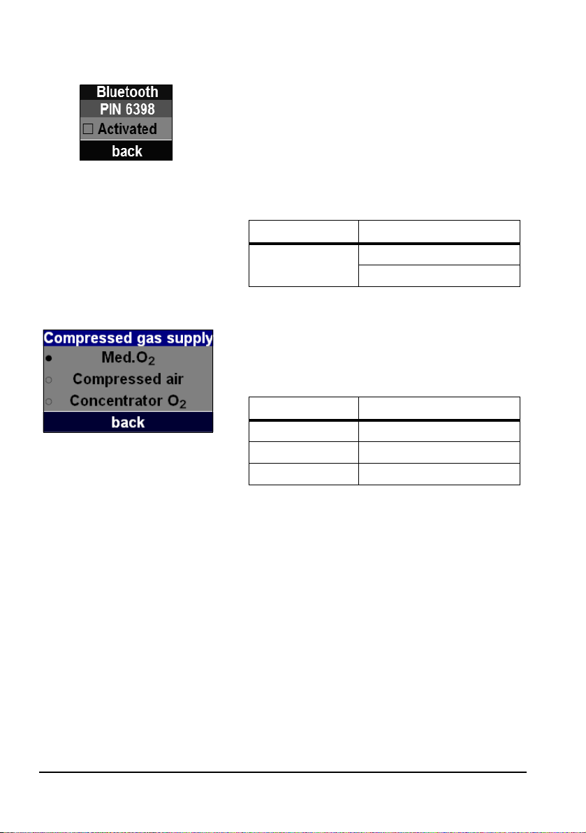
Bluetooth
Compressed gas supply
This menu enables you to activate or deactivate a Bluetooth connection. With the Bluetooth connection activated, an application documentation system can connect to
MEDUMAT Transport in order to retrieve application data.
For this you need the bluetooth pin 6398 displayed in this
menu. This menu only appears if the data communication
option has been enabled.
You can choose the following settings:
Parameters Setting range
Bluetooth
Activated
Deactivated
In this menu, you can select the type of pressurized gas
used. For this you must first activate the function in the
operator menu (see "8.6 User Settings" on page 105).
You can select the following types of gas:
Pressurized gas Description
Med.O
2
Compressed air Compressed air
Concentrator O
Medical oxygen
Concentrator oxygen
2
Notice:
The function keys "100% O
"O
concentration ↓" alarm are deactivated when
2
" and "FiO2" and the
2
compressed air is used.
Main menu EN 93
Page 94
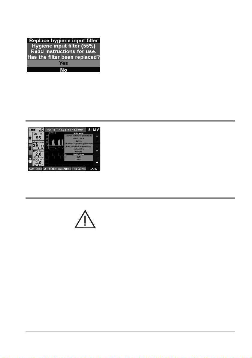
Hygiene input filter (optional)
In this menu you can reset the hygiene input filter counter
after a filter change. The remaining life of the hygiene input filter is shown in percent and is 100% when you have
changed the hygiene input filter.
Requirements for this function:
• Hygiene input filter installed
• Function activated in the operator menu (see "8.6
User Settings" on page 105)
7.8 Night colors
To ensure optimum readability of the display during nighttime use, you can activate the night colors. The readings
are displayed on a black background. This prevents glare.
You can set the brightness of the night colors in the Audio/
Video menu (see "7.6 Audio/Video" on page 90).
7.9 NVG (Night Vision Goggles)
94 EN Main menu
Warning!
Risk of injury from deactivated alarm LED, deactivated
acoustic alarm output and darkened display in NVG mode!
The alarms are barely perceptible as a result of the deactivated alarm LED, the deactivated acoustic alarm output
and the darkened display in NVG mode. This can injure the
patient.
• Always monitor the patient during ventilation.
• Only use the NVG option in the military sector.
Page 95

You can activate the NVG mode here. When the NVG
mode is activated, the device behaves as follows:
• Alarm LED deactivated
• Acoustic alarm output for all alarms permanently deactivated
• Coloring of the display optimized for night vision devices
• symbol in display and symbol in measurement
fields
• Display brightness reduced as per preset (see "7.6 Audio/Video" on page 90)
This menu item only appears if you enable the NVG option
in the operator menu (see "8.5 Options" on page 105).
This option is only permitted for use in the military sector.
A device in NVG mode does not comply with the following
standards with respect to alarm output:
• EN 60601-1-8
• EN 794-3/EN 10651-3
The operator assumes the resulting risk for operation.
Main menu EN 95
Page 96

8. Operator menu
In the operator menu, you can optimize the unit's settings
to suit the particular operating conditions. The operator
menu can be opened as follows when the device is started
up.
1. Switch on the device
2. Then press the two lower context-dependent
function keys simultaneously
(see image on left).
As soon as the progress bar turns blue, you are in the operator menu. As soon as the loading process has finished,
the start screen of the operator menu appears.
If the progress bar fails to turn blue, switch the device off
completely and then back on again. Then repress the two
function buttons.
Navigating the operator menu
To navigate in the operator menu, you can use either the
navigation knob or the context-dependent function buttons on the right of the display (see "5.3 Navigating in
menus" on page 44).
96 EN Operator menu
Notice:
You can see where you are in the operator menu
by means of the blue highlighting (blue selection
bar) of the respective field. The starting position of
the blue selection bar in the operator menu is
always the central field at the top in the menu bar
(here: Scroll: Page 1).
The menu bar also displays the respective page
name in English (field on left highlighted in brown,
here: Password Page).
Page 97

1. To call up a specific page of the operator menu, turn
the navigation knob until the required page is displayed.
2. Press the navigation knob.
The first menu item of the selected page is highlighted
in blue.
3. In order to call up a menu item on a page, turn the navigation knob until the selection bar is on the required
menu item.
4. Press the navigation knob.
The required menu item is highlighted in green.
5. To change a value, turn the navigation knob until the
required value is displayed.
6. Press the navigation knob.
The changed value is highlighted in blue and saved.
Additional functions are also available on some pages
of the operator menu. These are necessary for the individual device setting steps and are described in greater
detail in the corresponding sections of this chapter.
7. To exit a selected page, turn the navigation knob until
the selection bar is on BACK.
8. Press the navigation knob.
You can now call up another page in the operator
menu.
9. To exit the operator menu, press and hold the On/
Standby/Off button until the alarm LED stops flashing.
The device is switched off.
Operator menu EN 97
Page 98
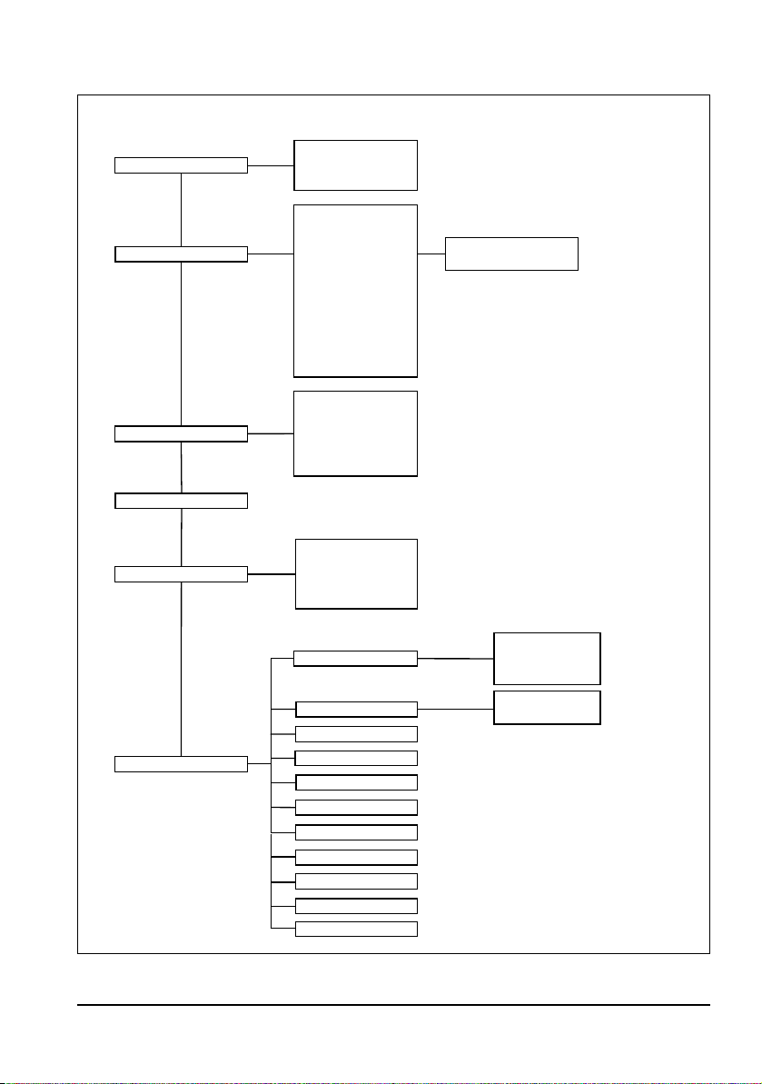
Ventilation Modes
Password Page
Edit ventilation settings
Edit alarm limits
Options
User Settings
Enter operator menu
Change operator password
Enter service menu
File Import/Export
Device ID
Bluetooth communication test
Bluetooth communication
NVG
IPPV
BiLevel + ASB
Language
Emergency mode
Vt/kg body weight
Allow patient height entry
Service Files
Mission Logs
Screenshots
Export Presets
Import Presets
Software Update
DE, EL, EN, ES, FR, IT, JA,
NL, PL, PT, RO, RU, SV,
TH, TR, DA, ZH, PT (BR),
CS, HU
Allow gas type selection
IPPV
BiLevel + ASB
CPAP + ASB
PCV
SIMV + ASB
S-IPPV
PRVC + ASB
aPCV
Pre-oxygenation
Inhalation
Hygiene input filter installed
Suction filter
Dust load on filter
Allow 0% audio volume
Allow alarm LED off
Allow NVG
MEDUMAT Transport operator menu
98 EN Operator menu
Page 99

8.1 Password Page
Before you enter the access code, the current software version of the unit is displayed on the start screen (Password
Page) of the operator menu. The operator menu is protected by a four-digit access code. On delivery, the access code
for the operator menu is "0000". You can enter the access
code for the operator menu either using the navigation
knob or the context-dependent function keys.
1. Press the button or the navigation knob to select
the "Enter operator menu" line.
2. Enter the access code.
3. Press the button or the navigation knob to confirm
your input.
In this menu, you can then also change the access code
("Change operator password").
8.2 Ventilation Modes
In this menu you can, firstly, set which ventilation modes
should be available on the user interface. Secondly, this
menu also allows you to specify the preset ventilation parameters and the corresponding alarm limits of the individual ventilation modes for the three patient groups Infant,
Child, and Adult:
1. Press the button or the navigation knob.
The selection bar is on BACK.
2. Turn the navigation knob until the selection bar is in the
required field.
3. By pressing the button or the navigation knob you
can activate or deactivate the required ventilation modes in the center column.
or
4. By pressing the button or the navigation knob you
can call up the presets of the required ventilation mode
for editing, via the "edit presets" field in the right column.
Operator menu EN 99
Page 100
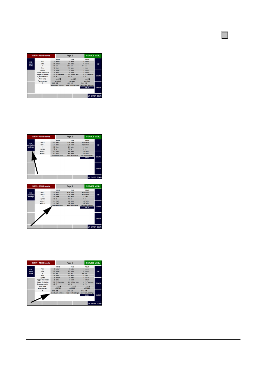
Notice:
If a ventilation mode is already deactivated , you
cannot call up its presets.
If you have selected and confirmed the "edit presets" field,
you enter the "Edit ventilation settings" submenu for the
required ventilation mode. This submenu is divided into
the patient groups Infant, Child, and Adult.
Further information on the possible settings can be found
in the "Advanced ventilation parameters" sections (see
"7.4 Advanced ventilation parameters" on page 87) and
"Technical data" (see "14. Technical Data" on page 142).
The non-selectable functions in a particular ventilation
mode are not shown.
5. To switch between the "edit ventilation settings" and
"edit alarm limits" submenus, press the function key in
the top left (see image).
6. To reset the alarm limits to the factory settings, select
the "reset alarm limits" field in the column of the respective patient group and confirm your selection.
Further information on the alarm limits can be found in
Section "7.2 Alarm Limits" (see "7.2 Alarm Limits" on
page 85).
100 EN Operator menu
7. To reset the ventilation settings to the factory settings,
select the "reset vent. settings" field in the column of
the respective patient group and confirm your selection.
 Loading...