

Page 1
MEDUMAT Standard a
Ventilator
Description and instructions for use
Page 2

EN
Contents
1. Overview . . . . . . . . . . . . . . . . . . . . 4
1.1 Device . . . . . . . . . . . . . . . . . . . . . . 4
1.2 Symbols used on the ventilator . . . . 7
2. Description of ventilator . . . . . . 10
2.1 Uses . . . . . . . . . . . . . . . . . . . . . . . 10
2.2 Owner/operator and user
qualification . . . . . . . . . . . . . . . . . 11
2.3 Ventilation function . . . . . . . . . . . 11
2.4 Controlled ventilation. . . . . . . . . . 13
2.5 Assisted ventilation. . . . . . . . . . . . 13
2.6 Check ventilation curve . . . . . . . . 14
2.7 Patient valve. . . . . . . . . . . . . . . . . 14
2.8 Modules. . . . . . . . . . . . . . . . . . . . 15
3. Safety instructions . . . . . . . . . . . 16
3.1 Safety regulations. . . . . . . . . . . . . 16
4. Installation . . . . . . . . . . . . . . . . . . 20
4.1 Wall mounting for STATION
MEDUMAT. . . . . . . . . . . . . . . . . . 20
4.2 Installation kit for the wall
mounting . . . . . . . . . . . . . . . . . . . 21
4.3 Connecting up the oxygen
cylinder . . . . . . . . . . . . . . . . . . . . 21
4.4 Ventilation hose . . . . . . . . . . . . . . 22
5. Using the ventilator . . . . . . . . . . 25
5.1 Switching on/self test . . . . . . . . . . 25
5.2 Selecting the ventilation settings. . 26
5.3 Select ventilation method . . . . . . . 28
5.4 Performing ventilation . . . . . . . . . 30
5.5 Monitoring ventilation . . . . . . . . . 30
5.6 Ventilation with PEEP Valve . . . . . 31
5.7 Ventilation with HME filter . . . . . . 32
5.8 Ventilating with bacteria filter. . . . 32
5.9 Terminating ventilation. . . . . . . . . 33
5.10 Alarm signals . . . . . . . . . . . . . . . . 33
5.11 Calculation of oxygen content/
remaining operating time . . . . . . . 37
5.12 Alternative ventilation
procedures . . . . . . . . . . . . . . . . . . 38
6. Hygienic preparation . . . . . . . . . 39
6.1 MEDUMAT Standard a. . . . . . . . . 39
6.2 Patient valve . . . . . . . . . . . . . . . . 40
6.3 Hose system . . . . . . . . . . . . . . . . 41
6.4 Components and accessories . . . . 42
6.5 Fittings . . . . . . . . . . . . . . . . . . . . 43
6.6 Cleaning, disinfecting and
sterilizing . . . . . . . . . . . . . . . . . . . 44
7. Functional checks . . . . . . . . . . . . 45
7.1 Preparation for functional check . 45
7.2 Obligatory checks . . . . . . . . . . . . 46
7.3 Check for leaks in the system. . . . 47
7.4 Check of patient valve . . . . . . . . . 48
7.5 Checking the minute volume . . . . 49
7.6 Check of maximal ventilation
pressure. . . . . . . . . . . . . . . . . . . . 51
7.7 Check assisted ventilation . . . . . . 52
7.8 Check of alarm systems . . . . . . . . 54
8. Troubleshooting . . . . . . . . . . . . . 57
8.1 Batteries . . . . . . . . . . . . . . . . . . . 59
8.2 Cut-out system . . . . . . . . . . . . . . 60
8.3 Adjustment of manometer. . . . . . 61
8.4 Change valve membrane in
patient valve . . . . . . . . . . . . . . . . 61
9. Servicing . . . . . . . . . . . . . . . . . . . . 63
9.1 Intervals. . . . . . . . . . . . . . . . . . . . 63
9.2 Sending in device. . . . . . . . . . . . . 64
9.3 Storage . . . . . . . . . . . . . . . . . . . . 64
9.4 Disposal. . . . . . . . . . . . . . . . . . . . 65
10. Supply schedule . . . . . . . . . . . . . . 66
10.1 Standard supply schedule . . . . . . 66
10.2 Accessories . . . . . . . . . . . . . . . . . 66
10.3 Spare parts . . . . . . . . . . . . . . . . . 67
11. Technical data . . . . . . . . . . . . . . . 68
11.1 Device . . . . . . . . . . . . . . . . . . . . . 68
11.2 Patient’s hose system. . . . . . . . . . 70
11.3 Pneumatics . . . . . . . . . . . . . . . . . 71
11.4 Resistance to interference . . . . . . 72
11.5 O
content when using Air Mix . . 72
2
2 Contents
Page 3

EN
11.6 Switching from Air Mix to
No Air Mix . . . . . . . . . . . . . . . . . . 73
12. Warranty . . . . . . . . . . . . . . . . . . . . 74
13. Declaration of conformity . . . . . 74
Contents 3
Page 4
EN
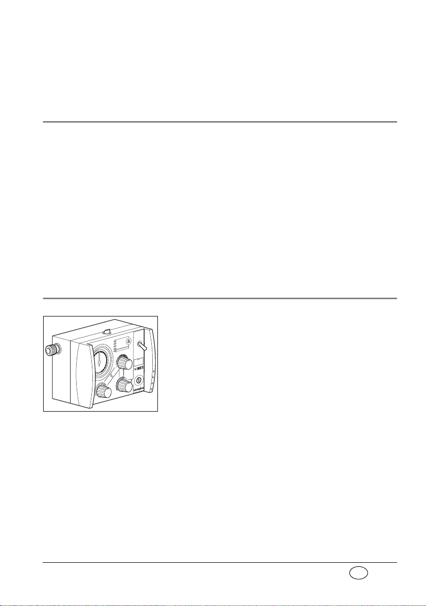
1. Overview
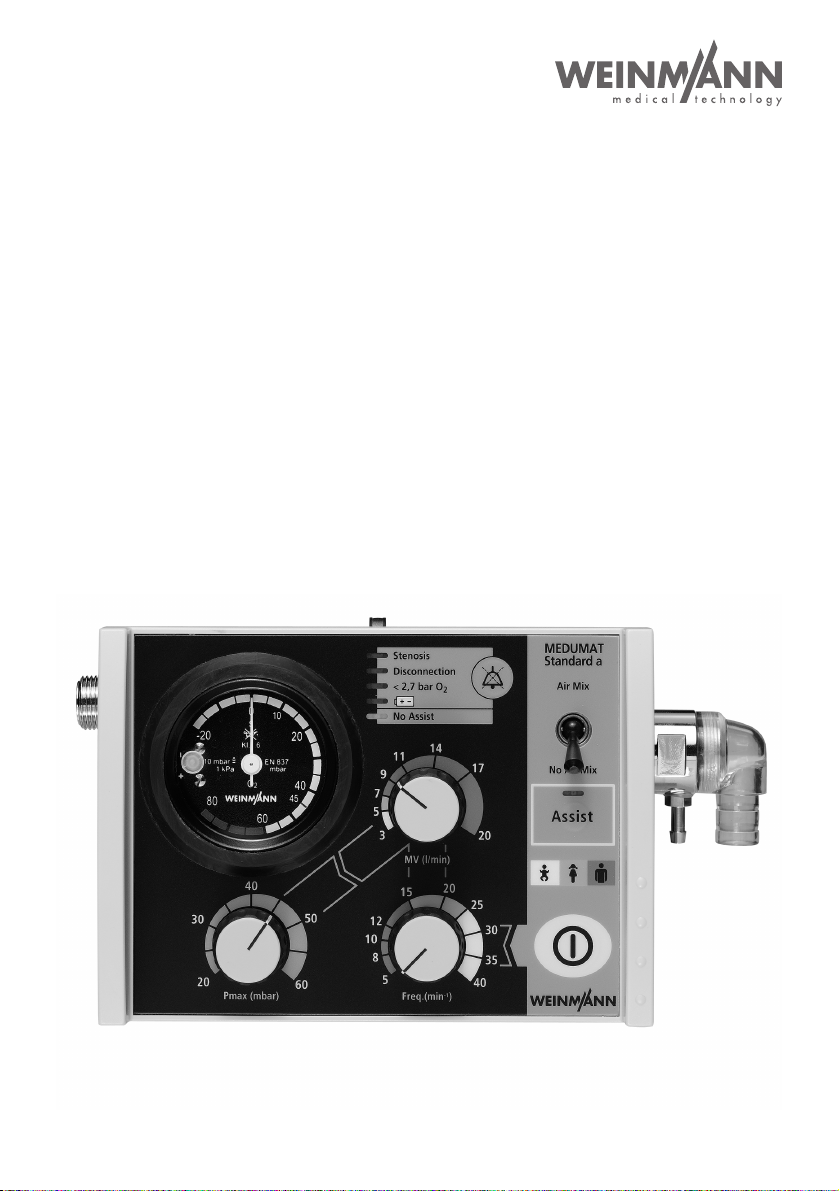
Control panel MEDUMAT Standard a
1 Ventilation pressure gauge
7 Colour code
Toddler (yellow, 10 kg to 30 kg)
Child (orange, 30 kg to 60 kg)
Adult (brown, 60 kg to 110 kg)
4 Air Mix/No Air Mix switch
3 Alarm acknowledgement2 Alarm panel
8 ON/OFF switch
9 Ventilation frequency regulator
5 Minute volume regulator
10 Max. ventilation pressure
regulator
6 On/Off switch,
assisted ventilation
1.1 Device
Stenosis
Disconnection
< 2,7 bar O
2
No assist
MEDUMAT
Standard a
Air Mix
No Air Mix
4 Overview
Page 5
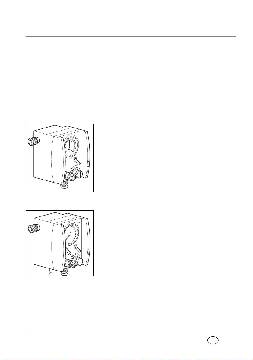
EN
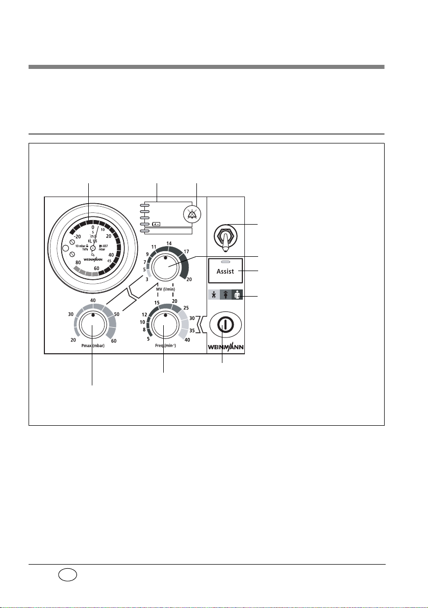
MEDUMAT Standard a connections
12 Catch for STATION MEDUMAT
wall mounting
11 Pressure gas connection
13 Connection for ventilation tube
14 Pressure gauge hose connection
15 Relief valve
16 Dust cover
17 Mixed air filter
12 Catch for STATION MEDUMAT
wall mounting
I
Overview 5
Page 6
EN
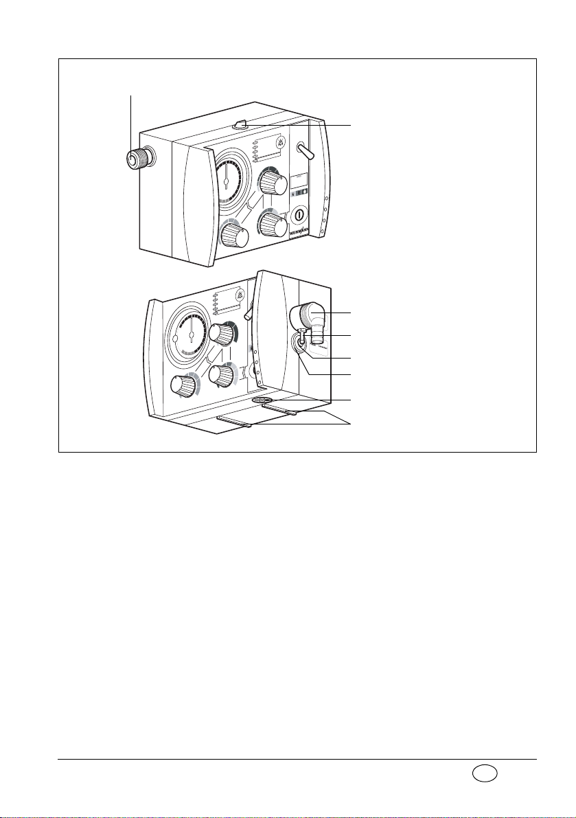
MEDUMAT Standard a device combinations
19 Ventilation hose
18 Ventilation mask
21 Filter
23 Patient valve
24 PEEP valve
22 Hose casing
25 Tube
or
20 Pressure gauge hose
Disposable hose system
6 Overview
Page 7
EN
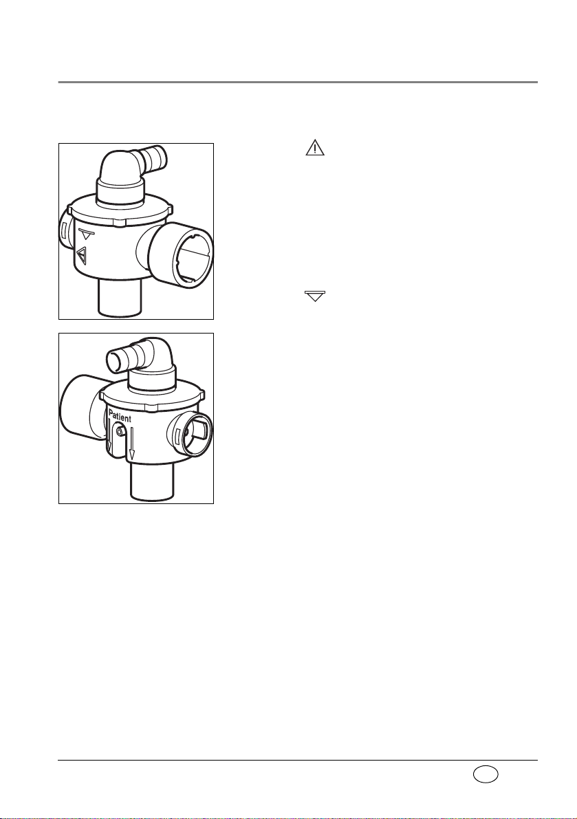
1.2 Symbols used on the ventilator
Position
> PSU< 134°
Patient valve
The symbol on the patient valve indicates that
the lip and valve membranes in the expiration and
spontaneous breathing arms must be changed immediately if they are crinkled, sticky or misshapen.
Under no circumstances continue to use the patient
valve for ventilation in this case, as malfunctions are
likely (note “7.4 Check of patient valve“ on
page 48).
The symbol indicates the correct position for
insertion of the lip membrane.
When connecting the patient valve, take care to
ensure that the direction of respiratory gas flow is
correct.
Overview 7
Page 8
EN
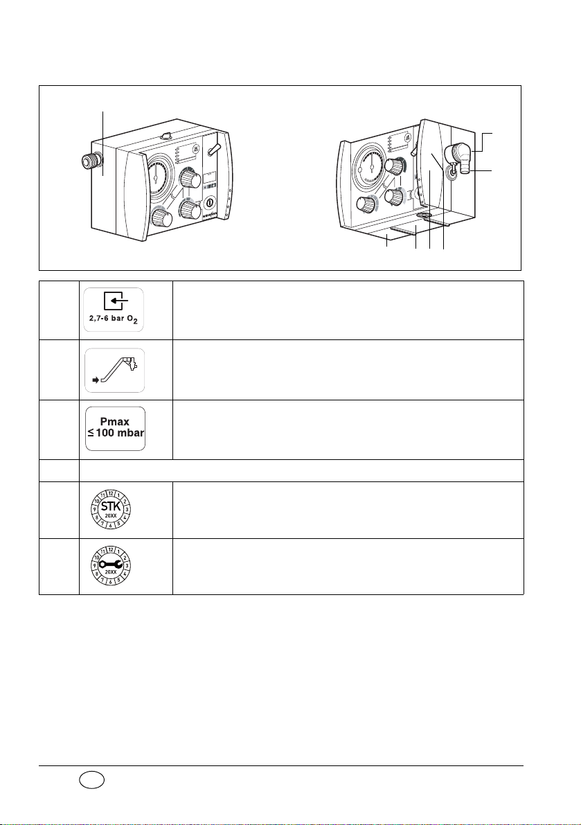
MEDUMAT Standard a
1
2
3
4567
1 Inlet 2,7 - 6 bar O2.
2 Tube system connection
3 Maximum pressure ≤100mbar
I
4
5 Servicing label: indicates when the next service is due.
8 Overview
Safety check and servicing label
Safety check label: (in Germany only) marks when the next safety
check as per §6 of the German law relating to users of medical
devices is required.
Page 9
EN
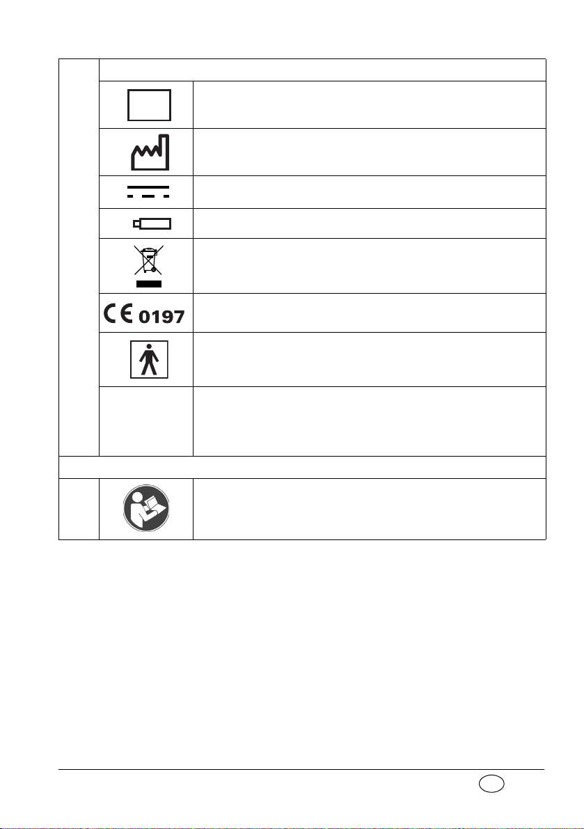
MEDUMAT Standard a device information plate
SN
6
IP24
Serial number of device
Date of manufacture
Direct voltage
3,6 V lithium battery
Do not dispose of device in domestic waste
CE symbol (confirms that the product conforms to the applicable
European directives)
Type BF application part
Degree of protection
– against the ingress of solid particles
– against access to hazardous parts
– against the ingress of water with a harmful effect
Other markings
7 Follow instructions for use
Overview 9
Page 10

EN
2. Description of ventilator
2.1 Uses
The MEDUMAT Standard a is an automatic (shortterm) ventilator with the option of assisted ventilation.
You can use MEDUMAT Standard a:
• to revive patients at the site of the emergency
• on a longer term basis in more protracted emergencies, e.g. fires.
You can use MEDUMAT Standard a while transporting patients:
• between the various rooms and departments of
a hospital;
• between the hospital and other premises;
• in emergencies;
• when transport over a considerable distance is
planned.
10 Description of ventilator
MEDUMAT Standard a:
• is designed to provide controlled ventilation to
persons of approx. 10 kg body weight or more,
or in the case of assisted ventilation, of approx.
15 kg body weight or more.
• is used to treat respiratory arrest;
• can be preset to parameters that ensure evenly
balanced ventilation provided that the selected maximum ventilation pressure P
• can be supplied with additional modules for
aspiration and oxygen inhalation. (N.B.
is not exceeded.
max
Page 11
EN
MEDUMAT Standard a cannot be used as a ventilator simultaneously with these modules.)
2.2 Owner/operator and user qualification
As an owner/operator or user, you must be familiar
with the operation of this medical device. Observe
the legal requirements for operation and use (in Germany, the regulations governing owner/operators of
medical devices apply in particular). Basic recommendation: get a person authorized by Weinmann
to provide you with proper instruction about the
handling, use and operation of this medical device.
2.3 Ventilation function
MEDUMAT Standard a operates within a pressure
range of 2.7 to 6 bar and at a flow rate of not less
than 70 l/min O
It uses high-pressure, medicinal-grade oxygen. An
external pressure reducer brings this down to the required operating pressure. The oxygen supply is fed
in at input valve.
Both the infinitely variable ventilation frequency and
the inspiration/expiration ratio of 1:1.67 in the case
of controlled ventilation are regulated by internal
electronic control mechanisms.
. It has an in-built power pack.
2
The gas for inspiration is routed to the patient
through the ventilation tube via the patient valve
and the ventilation mask or hose. A lip membrane
Description of ventilator 11
Page 12

EN
Air Mix
No Air Mix
Air Mix
No Air Mix
in the patient valve ensures that the expiration gas
can be exhaled through the expiration arm.
Regardless of the ventilation mode selected, the patient has the option of breathing spontaneously between ventilation strokes via the patient valve. In
this case, the patient draws air for breathing from
the ambient air.
With the Air Mix setting, in the case of mechanical
ventilation, atmospheric air is admixed to give an O
concentration generally of between 55 % and 85 %
at 10 mbar ventilation pressure (note “11.5 O
con-
2
tent when using Air Mix“ on page 72).
In certain indications and in cases where the surrounding atmosphere is contaminated, you can switch to
No Air Mix and ventilate with pure oxygen.
The injector unit is switched off when switching
from
Air Mix to No Air Mix. This increases minute vol-
ume which can result in the set pressure limit being
exceeded and a stenosis alarm (Stenosis) being trig-
gered. In this case, set minute volume correspondingly
lower.
In the opposite instance, in other words when
switching from
No Air Mix to Air Mix, the injector
unit is switched on. This reduces minute volume
which can lead to the set pressure limit being
. In this case, set minute volume correspondingly
shot
higher.
under-
2
12 Description of ventilator
Page 13
EN
2.4 Controlled ventilation
Mandatory ventilation
stroke: the device, not the
patient, determines the
time of the next breathing
stroke.
After being switched on, the MEDUMAT Standard a
is automatically in Controlled Ventilation mode. This
administers mandatory ventilation strokes to the intubated patient according to the ventilation values
set on the device.
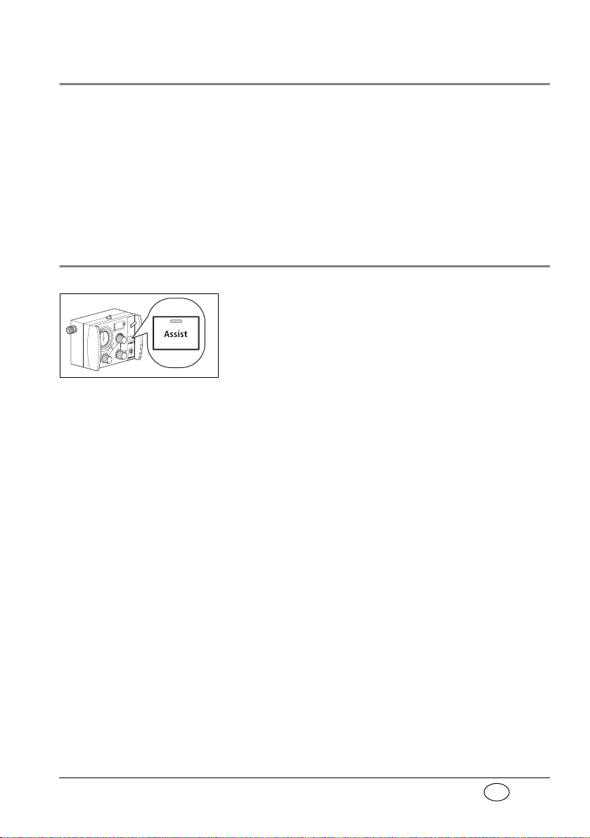
2.5 Assisted ventilation
In addition to Controlled Ventilation mode, the
MEDUMAT Standard a also has an Assisted Ventilation mode.
After you have switched on Assisted Ventilation
mode by pressing the
LED indicates this mode.
Triggered ventilation
stroke: the patient can trigger a ventilation stroke by
his own breathing efforts.
IPPV: intermittent positive
pressure ventilation (= controlled ventilation).
The patient now has the option of triggering a triggered ventilation stroke within a time window of 40
% of expiration. To do so, the patient must generate
a flow of over 6 l/min. by his own breathing efforts.
If the breathing efforts of the patient are not sufficient to trigger, the patient automatically receives a
mandatory ventilation stroke at the end of the time
window, so that the set minute volume is guaranteed.
With this function, the ventilation strokes of the device can be synchronised with the breathing efforts
of the patient.
Between the mandatory ventilation strokes of the
device, the patient has the option of breathing in air
from the surrounding atmosphere via the patient
valve.
Assist key, a flashing green
Description of ventilator 13
Page 14
EN
If the patient does not trigger the device, an alarm is
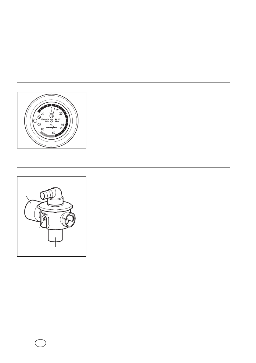
Respiration hose connection
Expiration
tube
Connection
for pressure
gauge tube
Mask/tube connection
Spontaneous
breathing tube
triggered. The patient continues to receive controlled ventilation.
2.6 Check ventilation curve
The ventilation curve is checked at ventilation
pressure gauge.
2.7 Patient valve
The gas for inspiration is channelled into the
patient’s airways through the patient valve.
It is designed so that spontaneous breathing is possible, even if the MEDUMAT Standard a fails, regardless of which ventilation mode you have selected.
14 Description of ventilator
Page 15
EN
2.8 Modules
M
OD
UL
O
x
y
g
e
n
O
2
0
5
1
0
1
5
l/min
O
2
MODUL
Combi
O
2
Modules with additional functions can be attached
to MEDUMAT Standard a.
Please refer to the directions for use enclosed with
the modules for exact details of how to fit and operate these. It is essential to read these directions carefully before using the modules. The most important
points are listed below:
Oxygen MODULE
The Oxygen MODULE enables you to apply oxygen
inhalation.
Put the switch marked
O
into the “I“ position. Se-
2
lect the desired oxygen volume by turning the knob
marked
l/min to a setting between 0 and 15 l/min.
You can check this setting on the volume manometer.
Combi MODULE
The Combi MODULE enables you to apply both
oxygen inhalation and suction.
For inhalation put the switch marked
position. Select the desired oxygen volume by turning
the knob marked
l/min to a setting between 0 and
15 l/min. You can check this setting on the volume
manometer.
For suction switch the tumbler marked
position. The suction pressure is locked at -0.5 bar.
O2 into the “I“
Vac to the “I“
Description of ventilator 15
Page 16

EN
3. Safety instructions
3.1 Safety regulations
For your own safety, the safety of your patients, and
to comply with the requirements of EU Directive 93/
42/EEC, please observe the following points:
General
• Please read the directions for use carefully. They
are an integral part of the ventilator and should
be available for reference at all times.
• Before starting to work with
MEDUMAT Standard a, you must understand
how to operate it.
• Please comply with section “6. Hygienic preparation“ on page 39 to prevent infection or bacterial contamination.
• MEDUMAT Standard a should be used only by
medically qualified personnel who have had
training in ventilation techniques. Incorrect use
can cause severe physical injury.
16 Safety instructions
• It is advisable for you to have servicing and repairs carried out only by the manufacturer,
Weinmann, or by qualified technicians expressly
authorized by Weinmann.
• If third-party items are used, functional failures
may occur and fitness for use may be restricted.
Biocompatibility requirements may also not be
met. Please note that in such cases, any claim
under warranty and liability will be voided if neither the accessories nor genuine replacement
Page 17
EN
parts recommended in the instructions for use
are used.
• MEDUMAT Standard a should be used only for
the purposes for which it is designed (note “2.1
Uses“ on page 10).
• MEDUMAT Standard a is not designed for use
under hyperbaric conditions (pressure chamber).
• MEDUMAT Standard a should never be used
with flammable anaesthetics.
• In the case of use in poisoned or low-oxygen
atmospheres, do not operate the
MEDUMAT Standard a with the „Air Mix“
setting or in Assist mode.
• A back-up ventilator should always be available
in case of technical failure.
Warning: • Modifications may not be made to the device.
Have modifications to the device carried out only
by the manufacturer, Weinmann, or by specialist
staff expressly authorized by the manufacturer.
Oxygen
Highly-compressed oxygen can lead to spontaneous
explosive reactions in combination with flammable
substances (fat, oil, alcohol, disinfectants, etc.):
• All screw connections and other components of
the ventilator must be kept absolutely free of oil
and grease.
• Always wash your hands before starting to work
on the oxygen supply.
• Smoking and open flames are strictly prohibited
in the vicinity of all fittings containing or transporting oxygen.
• During assembly and when changing the oxygen
cylinder, only hand pressure should be used
Safety instructions 17
Page 18

EN
when tightening the screw connections to the
cylinder and to the pressure reducer. Never use
tools for this purpose. Excessive tightening damages the screw threads and seals and can cause
leaks.
• Protect oxygen cylinders from accidental falls. If
a cylinder falls, the pressure reducer or the valve
may break off and cause a violent explosion.
Important note • Always open the valve of the oxygen cylinder
slowly to prevent pressure damage to the other
fittings.
• The oxygen cylinder should never be completely
emptied as this may allow moisture-containing
air to enter the cylinder and cause corrosion.
Operation
• Both the patient and the ventilator must be kept
under constant observation during ventilation.
• Make sure that neither the expiration tube nor
the spontaneous breathing tube on the patient
valve is blocked or impeded in any other way,
e.g. by the patient’s position.
18 Safety instructions
• MEDUMAT Standard a must never be used simultaneously with a module as this would make
it impossible to work to the selected parameters.
Note • Disposable hose systems WM 28110 (2 m) and
WM 28188 (3 m) are only intended to be used
once.
Software
• Extensive validation tests have been performed
to minimize risks arising from software errors.
Page 19

EN
Accessories
• Please protect the silicone and rubber components against UV radiation and prolonged exposure to direct sunlight, as this can make them
brittle and friable.
Safety instructions 19
Page 20
EN
4. Installation
A permanent mounting is usually necessary only
when MEDUMAT Standard a is installed as a fixture
in rescue vehicles, helicopters or aircraft. In these
cases either the STATION MEDUMAT or installation
kits are available as accessories.
If MEDUMAT Standard a is supplied complete with
carrying platform, it is ready for use and requires no
further installation. Separate directions for use are
supplied with the carrying platform.
Functional tests must be carried out after installation
(note “7. Functional checks“ on page 45).
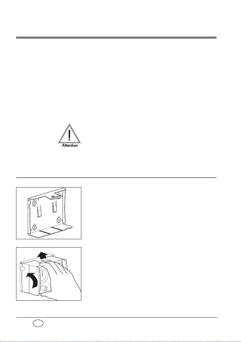
4.1 Wall mounting for STATION MEDUMAT
The wall mounting for the STATION MEDUMAT
should be installed at an appropriate place, e.g., on
a side panel inside the vehicle. Please refer to the
sheet enclosed with the STATION MEDUMAT for
details of dimensions and the installation procedure.
20 Installation
To place MEDUMAT Standard a in the wall mounting,
first insert the slides on the underside of the ventilator
into the matching grooves in the STATION MEDUMAT
and then press the MEDUMAT Standard a inwards
until the catch snaps into the fastening at the top of
the STATION MEDUMAT.
Page 21
EN
4.2 Installation kit for the wall mounting
A number of kits are available for installing a wall
mounting, e.g. on a panel inside a vehicle. The kit
size varies according to the number of modules attached to the MEDUMAT Standard a.
Please refer to the sheet enclosed with each installation kit for details of dimensions and installation
procedure.
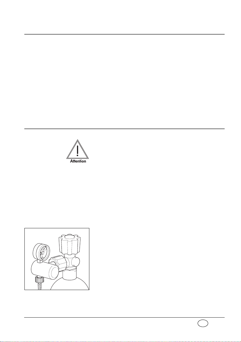
4.3 Connecting up the oxygen cylinder
Wash your hands thoroughly before any work on the
oxygen supply. Hydrocarbon compounds (e.g. oils,
greases, alcohol for cleaning, disinfectants, hand
cream or sticking plaster) can lead to explosive reactions if they come into contact with highly-compressed oxygen.
Never use wrenches or similar tools to tighten or
loosen the screw connections.
Removal of empty cylinder
1. Close the valve of the oxygen cylinder.
Switch on MEDUMAT Standard a with ON/OFF
switch. This exhausts any residual oxygen and
depressurizes the ventilator. Wait until the pressure gauge on the pressure reducer shows
oxygen content before uncoupling the screw
connection by hand.
2. First switch off MEDUMAT Standard a again.
3. Then loosen the screw connection to the
cylinder.
Installation 21
0 bar
Page 22
EN
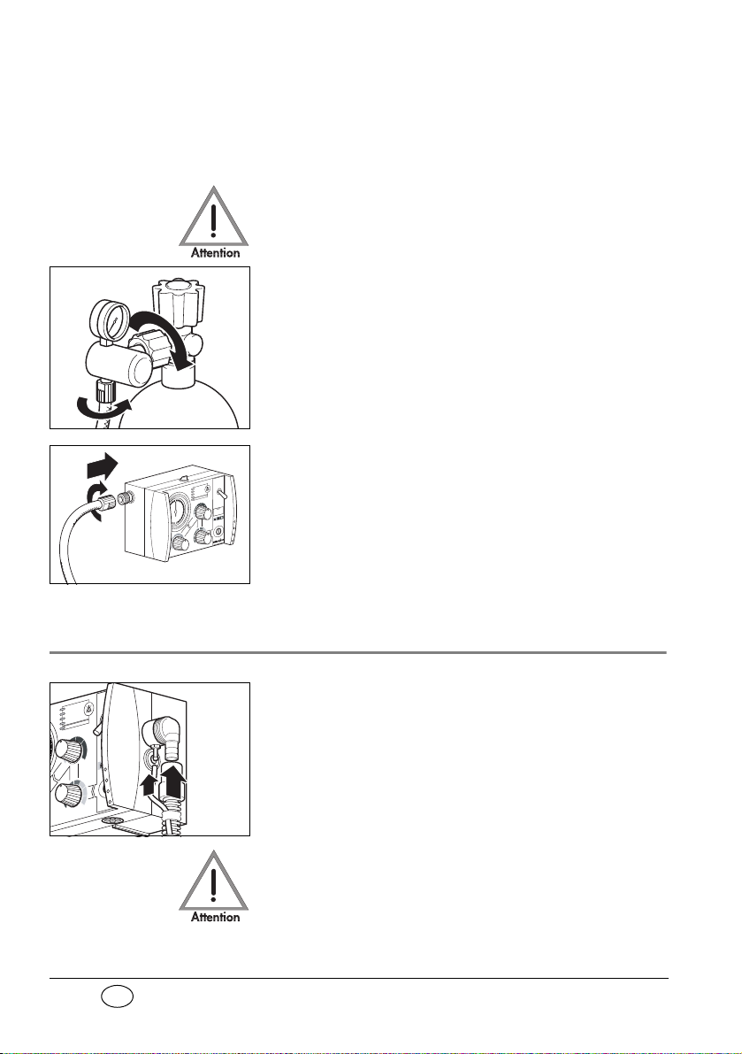
Connecting up new cylinder
I
1. First open the valve of the new oxygen cylinder
and close it again quickly. This will blow out any
particulate matter.
Keep the valve opening away from the body,
making sure that neither yourself or other persons can be injured by escaping particles!
2. Next couple the pressure reducer to the valve on
the oxygen cylinder with the fluted connecting
nut. Tighten up the nut by hand.
3. If the pressure hose is not already connected to
the exit valve of the pressure reducer, make this
connection with the G 3/8 connecting nut.
4. Screw the other end of the pressure hose on to
pressure gas connection on the
MEDUMAT Standard a if this has not yet been
done.
4.4 Ventilation hose
22 Installation
1. Slide the pressure gauge hose onto the
connection.
2. Slide the ventilation tube onto the connection.
Make sure that the pressure gauge hose already
connected is not kinked. If necessary, turn the
ventilation tube while sliding on as appropriate.
Do solely grasp the ventilation tube by its end (position of arrow in adjacent drawing). Otherwise the
hose may become damaged or tear.
Page 23
EN
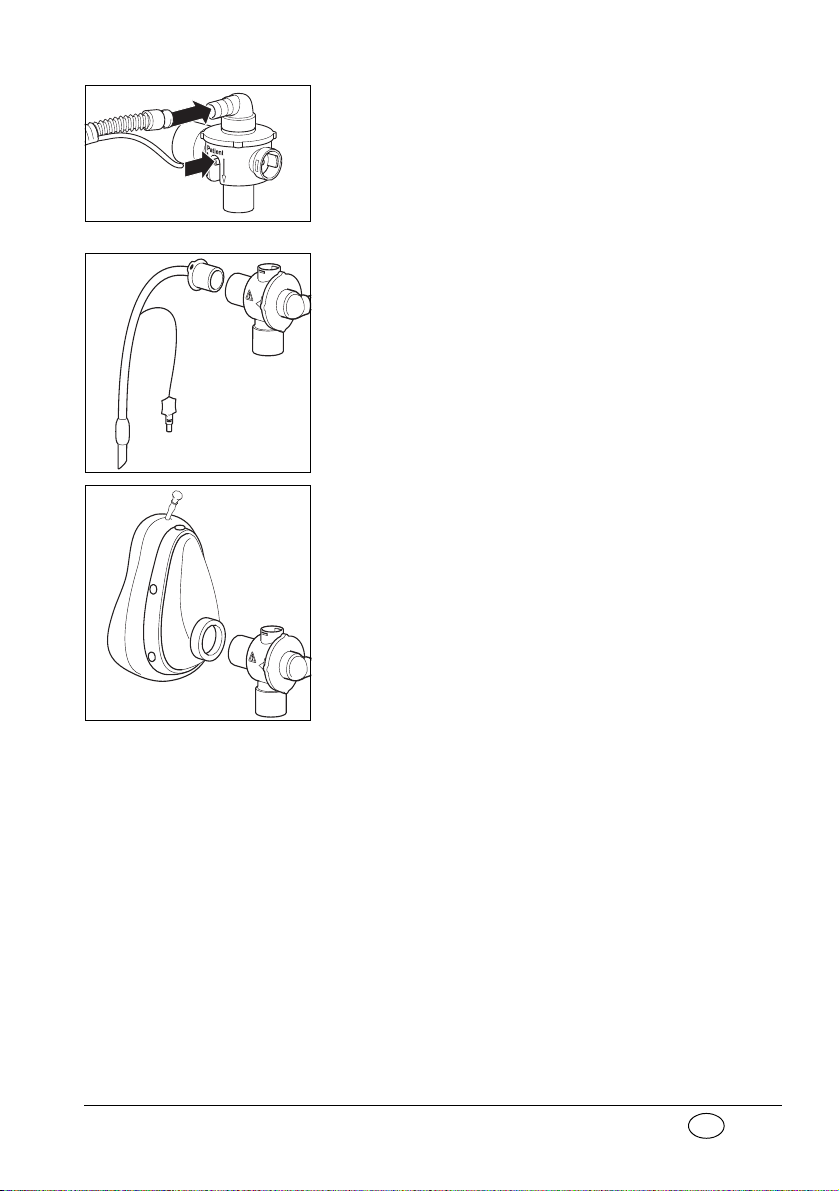
3. Plug the other end of the ventilation tube and the
Po
s
it
i
o
n
>
PS
U
<
1
3
4
°
P
o
s
i
t
io
n
>
P
S
U
<
1
34°
pressure measurement tube onto the patient
valve.
4. If the patient is intubated, insert the patient
valve into the tube,
or
if a mask is being used for ventilation, insert the
patient valve into the connector on the mask.
(This is identical with the connector on the tube.)
HME-Filter
If a heat and moisture exchanger (HME) filter is
required, this should be installed between the patient-side connector on the patient valve and the
tube or mask.
Always follow the manufacturer’s directions for use.
Installation 23
Page 24

EN
PEEP Valve
If a PEEP valve is needed, this should be inserted into
the expiration tube on the patient valve.
Always follow the manufacturer’s directions for use.
Bacteria filter
If a bacteria filter is used, fit it between the device
outlet port and the ventilation tube.
Always follow the manufacturer’s directions for use.
24 Installation
Page 25

EN
5. Using the ventilator
Stenosis
Disconnection
< 2,7 bar O
2
No assist
5.1 Switching on/self test
1. Open the valve of the oxygen cylinder slowly.
The pressure gauge will now show the pressure
in the cylinder.
2. Where appropriate, calculate how long the remaining oxygen will last (note “5.11 Calculation
of oxygen content/remaining operating time“
on page 37). Always change the cylinder in good
time, e.g., when the pressure is lower than
50 bar, to ensure that oxygen is available for an
adequate period.
3. Select the desired settings for the ventilation
(note “5.2 Selecting the ventilation settings“ on
page 26).
4. Switch on the MEDUMAT Standard a with ON/
OFF switch. The ventilator will then run a self test
lasting approx. 2 seconds.
If no fault is detected, the five LEDs in alarm field
come on and a brief alarm sounds. After that, the
MEDUMAT Standard a starts working with the
set ventilation values in „Controlled Ventilation“
mode.
If an error is found, the LED’s in alarm panel will
start to flash. If this happens,
MEDUMAT Standard a must not be used for
ventilation.
Using the ventilator 25
Page 26

EN
5.2 Selecting the ventilation settings
MEDUMAT
Standard a must
never be used
simultaneously
with a module as this
would make it impossible
to work to the selected
parameters.
Air Mix
No Air Mix
The settings can be selected either before or after the
MEDUMAT Standard a is switched on. We recommend selection before switching on to prevent
unnecessary waste of oxygen.
Air Mix/No Air Mix
In the case of a given indication, it is possible to
ventilate using pure oxygen or using mixed air.
1. For mixed air, set switch to
The oxygen concentration administered will normally lie somewhere between 55% and 85% at
a ventilation pressure of 10 mbar. You can read
off the exact figure from relevant diagram (note
“11.5 O
content when using Air Mix“ on
2
page 72).
No Air Mix setting should be used when the
The
surrounding atmosphere is polluted or has a low
oxygen content or when the indication requires this.
Air Mix.
No Air Mix
26 Using the ventilator
Air Mix
2. Set Switch to
No Air Mix.
When the ventilator is switched from an air/oxygen mixture (
Air Mix) to pure oxygen (No Air Mix),
the minute volume will vary only within the set
tolerances (note “11. Technical data“ on
page 68).
Page 27

EN
Respiratory frequency
MV (l/min)
1. The respiratory frequency can be set with
regulator knob.
Minute volume
1. The minute volume can be set with regulator
knob.
Recommendation for breathing frequency and
minute volume in the case of controlled
ventilation:
Toddler
yellow
Body weight 10 - 30 kg 30 - 60 kg 60 - 110 kg
Respiratory
frequency
Minute volume 3 - 5 l/min 5 - 7 l/min 7 - 13 l/min
25 - 40 min-115 - 25 min-18 - 15 min
The values given in the table are recommendations.
Deviating values are possible for certain indications.
Child
orange
Adult
brown
-1
Maximal ventilation pressure
1. The ventilation pressure can be set with regulator knob max. ventilation pressure.
Recommendations for the Maximal ventilation
pressure:
Intubation Mask ventilation
45 mbar 20 mbar
The values given in the table are recommendations.
Deviating values are possible for certain indications.
Using the ventilator 27
Page 28

EN
If the set level is reached, e.g. in cases where compli-
Ventilation pressure
in mbar
Time in s
Expiration
Inspiration
Ventilation frequency
30
20
10
Example of a ventilation curve in Controlled
Ventilation mode:
ance is inadequate, MEDUMAT Standard a sets off a
stenosis alarm (note “ Stenosis alarm“ on page 34).
5.3 Select ventilation method
Ventilation in Controlled Ventilation
mode
The MEDUMAT Standard a is automatically in
Controlled Ventilation mode when switched on.
The LED in key
The patient is supplied with air for breathing at an inspiration/expiration ratio of 1: 1.67 according to the
set ventilation parameters (note “5.2 Selecting the
ventilation settings“ on page 26).
Assist does not come on.
Ventilation in Assisted Ventilation
mode
28 Using the ventilator
To switch on „Assisted Ventilation“ mode, please
press key
Assist.
„Assisted Ventilation“ mode is indicated by the
green LED in key
Assist flashing.
Page 29

EN
Triggered ventilation
Time in s
Inspiration
30
20
10
Trigger
window
Triggered
ventilation pulse
Expiration
Trigger
pulse
Spontaneous breath
Example of a ventilation curve in Assisted
Ventilation mode:
stroke: the patient triggers
a ventilation stroke
through his own breathing
effort.
During assisted ventilation, the patient likewise receives a controlled ventilation stroke in accordance
with the ventilation frequency set.
In addition, the patient is given the option of triggering the device himself before a controlled ventilation
stroke. This synchronises the controlled ventilation
strokes with the breathing efforts of the patient.
Note:
different trigger points in
consecutive phases can
lead to a change in the inspiration/expiration ratio.
The set values for breathing frequency and minute
volume are maintained.
The patient furthermore has the option of performing a spontaneous breath via the patient valve between triggered ventilation strokes. In this case, the
patient draws air for breathing from the ambient air.
If the patient fails to trigger the device within the
time window in two consecutive phases, i.e., is
making no more breathing effort, the No Assist
alarm is triggered (note “5.10 Alarm signals“ on
page 33).
You end „Assisted Ventilation“ mode by pressing key
Assist. The MEDUMAT Standard a then continues
working in “Controlled Ventilation” mode. The LED
in key
Assist goes out.
Using the ventilator 29
Page 30

EN
5.4 Performing ventilation
Intubation
The patient will normally be intubated before the
patient valve is connected to the tube.
1. Attach the patient valve to the connector of the
tracheal tube.
2. Monitor the respiratory parameters during ventilation, e.g., with Weinmann’s CAPNOCOUNT mini
WM 97144. This will indicate whether the tube
is correctly positioned and ventilation is adequate.
Ventilation mask
1. Attach the mask to the patient valve.
2. Place the mask over the patient’s mouth and
nose.
3. Stretch the mask over the head and use
Esmarch’s grip to seal it hermetically.
If necessary, insert a Guedel tube to keep the airways
open before putting on the mask.
5.5 Monitoring ventilation
The patient must be monitored constantly during
ventilation.
Ventilation pressure gauge shows the ventilation
sequence.
High airway resistance, e.g., caused by obstructions
or external cardiac massage, tend to affect minute
volume (exact details can be obtained from the
30 Using the ventilator
Page 31

EN
manufacturer Weinmann on request). If the preset
Example for the ventilation sequence before and
after the lung compliance diminishes
maximal ventilation pressure is exceeded in two successive inspiration phases (note “ Stenosis alarm“ on
page 34) you should use a respirometer to check the
ventilation volume actually being received by the patient. The respirometer can be attached to the expiration tube on the patient valve with an adapter.
Monitor the respiratory parameters during ventilation,
e.g., with Weinmann’s CAPNOCOUNT mini
WM 97144.
If lung compliance diminishes during ventilation in
the
No Air Mix setting, the ventilator will react with
an increase in ventilation pressure at constant volume. For details of how MEDUMAT Standard a reacts in the
“11.5 O
Air Mix setting, please refer to Section
content when using Air Mix” on page 72.
2
5.6 Ventilation with PEEP Valve
A PEEP valve can be fitted to the expiration tube on
the patient valve with an adapter.
This valve makes it possible to use positive endexpiratory pressure (PEEP). Please see the PEEP valve
instructions for details of settings.
Using the ventilator 31
Page 32

EN
5.7 Ventilation with HME filter
A conventional heat and moisture exchange (HME)
filter with standard 15/22 mm connectors can be
fitted on the inspiration tube of the patient valve for
hygienic purposes and to condition the inspired air.
This will increase both inspiratory and expiratory
resistance. You should therefore monitor ventilation
pressure and ventilation volume very carefully.
A close watch must be kept for any increase in dead
space, especially in children.
Always read and follow the manufacturer’s
directions for use.
5.8 Ventilating with bacteria filter
To protect the patient and the environment from infection, you can connect the upgrade set for the device outlet port filter between the device outlet port
and the ventilation tube. Always monitor the exchange of air at the device inlet carefully.
32 Using the ventilator
Follow the instructions for use for the device outlet
port filter upgrade set.
Page 33

EN
5.9 Terminating ventilation
Stenosis
Disconnection
< 2,7 bar O
2
No assist
Important note!
Never empty the oxygen
cylinder completely. Return
the cylinder for filling while
it still contains residual pressure. This prevents entry of
moist atmospheric air that
can cause corrosion.
5.10 Alarm signals
1. Check the oxygen supply on the gauge on the
pressure reducer gauge. If the pressure has
dropped to 50 bar or less, the cylinder should be
refilled or a reserve cylinder should be available in
order to ensure that the ventilator will be able to
function properly.
2. Close the valve of the oxygen cylinder.
3. Switch off MEDUMAT Standard a. ON/OFF
switch must be kept pressed down for at least
2 seconds until the LEDs in the alarm panel light
up. This is a safety device to prevent the ventilator from being switched off unintentionally.
Alarm panel signals the following alarms:
Stenosis: Stenosis or a rise to maximal ventila-
tion pressure P
in two successive
max
inspiration phases
Disconnection:Disconnection between
MEDUMAT Standard a and the
patient in two successive inspiration
phases
< 2,7 bar: Drop in oxygen pressure to below
2.7 bar
: Battery charge inadequate
Using the ventilator 33
Page 34

EN
No Assist: in „Assisted Ventilation“ mode,
patient fails to trigger within the time
window in two consecutive phases.
In addition to all the visual alarms, an acoustic alarm
is triggered. Only in the case of the No Assist alarm,
is the acoustic alarm triggered with a delay of 1 minute.
The patient valve is designed to enable spontaneous
breathing in case of equipment failure.
When is the alarm set off?
An alarm signal is given as soon as any one of the
aforementioned functional failures occurs. The relevant LED starts to flash and an acoustic signal
sounds.
Simultaneous disconnection and drop in oxygen
pressure will initially set off only the < 2,7 bar alarm.
Stenosis alarm
Actual ventilation pressure exceeds the level set with
regulator knob max. ventilation pressure.
Up to Serial No. 1799 MEDUMAT Standard a switches to expiration immedi-
From Serial No. 1800 MEDUMAT Standard a briefly switches to expiration
34 Using the ventilator
ately if the maximum ventilation pressure is exceeded.
This does not affect the set frequency. Old appliances
(up to serial no.1799) that have been given a new
board in the course of repairs or servicing behave in
the same way as appliances from serial no. 1800 onwards.
whenever the maximum ventilation pressure is exceeded but tries to continue inspiration in the same
inspiration phase.
Page 35

EN
If the maximum ventilation pressure is exceeded for
a second time during the same inspiration phase, the
device finally switches to expiration and vents the
patient tube system completely. The next inspiration
starts with the following ventilation stroke according
to the frequency selected. The frequency is not
affected.
The alarm is set off when airway resistance is exceeded in two successive inspiration phases. This is to
prevent false alarms, alarms caused by coughing for
example.
Disconnection alarm
The rise in pressure during the inspiration phase is
less than 5 mbar. This is generally due to an interruption in the breathing system.
The alarm is set off when the rise in pressure is less
than 5 mbar in two successive inspiration phases.
< 2,7 bar O2 alarm
Oxygen pressure at the pressure connection to
MEDUMAT Standard a has dropped to less than
2.7 bar. The reason is usually an almost empty
oxygen cylinder.
In this case MEDUMAT Standard a will no longer
function correctly because the operating parameters
will not lie within the permissible limits.
Alarm
The battery is failing. Failure of the automatic ventilation function must be expected. Immediate steps
must be taken to provide alternative ventilation
(note “5.12 Alternative ventilation procedures“ on
page 38).
Using the ventilator 35
Page 36

EN
No Assist Alarm
In “Assisted Ventilation” mode, patient fails to trigger within the time window in two consecutive
phases.
The LED in alarm field flashes and the acoustic alarm
is triggered after a 1-minute delay.
Cancelling acoustic alarm
The acoustic alarm can be temporarily cancelled by
pressing alarm acknowledgement:
Stenosis: 30 Seconds
Disconnection: 30 Seconds
< 2,7 bar: 30 Seconds
: 120 Seconds
No Assist: 120 Seconds
The optical alarm will continue to flash.
If the cause of the alarm is not eliminated, the acoustic alarm will start to sound again after a short interval.
Both the optical and the acoustic alarm are cancelled
automatically as soon as the cause is eliminated.
36 Using the ventilator
Page 37

EN
5.11 Calculation of oxygen content/remaining
Real ventilation time(min)
oxygen content (l)
MV (l/min)
----------------------------------------------
100
O
2
-concentration()
--------------------------------------------------¥=
x
Real ventilation time(min)
1000l
11l/min
---------------------
100
100%
----------------¥91min 1h31min===
x
operating time
Oxygen content of cylinder
Oxygen volume = Volume of cylinder x cylinder pressure.
Cylinder volume x cylinder pressure = oxygen content
Example 1
Example 2
Real ventilation time
Example 1:
O
-content = 1000 l; MV = 11 l/min; 100% O2 (No Air Mix).
2
This gives the following equation:
10 l x 200 bar = 2000 l
10 l x 100 bar = 1000 l
The real ventilation time is prolonged when MEDUMAT Standard a is switched to
Mix.
Using the ventilator 37
Air
Page 38

EN
5.12 Alternative ventilation procedures
If MEDUMAT Standard a ceases to function during a
ventilation procedure, the following alternatives can
be applied:
Ventilation bags
1. Remove the patient valve from the tube or the
mask.
2. Replace it with the ventilation bag, e.g. a Weinmann
COMBIBAG WM 11000, and perform manual
ventilation.
A ventilation aid
Alternatively, you can perform mouth/mask ventilation with a Weinmann LIFEWAY WM 10580.
Exhaustion of oxygen supply
In emergency situations when the oxygen supply
runs out, MEDUMAT Standard a can also function
with compressed air.
38 Using the ventilator
Page 39

EN
6. Hygienic preparation
Whenever MEDUMAT Standard a and accessories
have been used, they must undergo a hygienic
preparation. Observe the instructions regarding use
of disinfectant. We recommend gigasept
for disinfecting by immersion and terralin
for disinfecting by wiping.
Make sure you perform a functional check after
every hygienic preparation (note “7. Functional
checks“ on page 45).
This product may contain disposable items. Dispos-
able items are intended to be used only once. So use
these items only once and do
Reprocessing disposable items may impair the functionality and safety of the product and lead to unforeseeable reactions as a result of ageing,
embrittlement, wear, thermal load, the effects of
chemical processes, etc.
®
FF (new)
®
protect
not reprocess them.
6.1 MEDUMAT Standard a
MEDUMAT Standard a’s outer casing simply needs
to be wiped with a dry or damp cloth.
Never immerse MEDUMAT Standard a in disinfectant or other fluids. Just wipe over with disinfectant.
Otherwise damage may be caused to the device,
thus endangering users and patients (note “6.6
Cleaning, disinfecting and sterilizing“ on page 44).
Hygienic preparation 39
Page 40

EN
6.2 Patient valve
Lip
membrane
Disc
membrane
Expiration
tube
Disc
membrane
Spontaneous
breathing
tube
Always grasp the hoses by their ends. Otherwise you
might damage or tear them.
1. Disconnect the patient valve from the hoses.
2. Dismantle the patient valve as shown in the adjacent diagram. It is neither necessary nor permissible to remove the membrane in the
spontaneous breathing nozzle for cleaning and
disinfection.
3. Clean the components under running water.
4. Brush the parts of the patient valve inside and
outside thoroughly, using a normal soft laboratory bottle brush.
5. Carry out sterilization/disinfection.
6. Make sure all internal and external surfaces are
thoroughly wetted and free from bubbles. Wait
for the full disinfection time to elapse.
7. Then rinse the components thoroughly inside
and out with distilled water.
40 Hygienic preparation
8. Dry the components thoroughly.
9. Reassemble the patient valve.
When reassembling, make sure that the lip
membrane is correctly positioned. The patient
valve may not function properly if it contains residual water!
Crinkled, misshapen and sticky lip and valve
membranes must be replaced.
10. Always perform a functional check before reusing the valve (note “7.4 Check of patient valve“
on page 48).
Page 41

EN
6.3 Hose system
I
Caution! Only reusable hose system WM 22520 (scope of
supply) is suitable for the hygienic preparation described here. Do
WM 28110 (2 m) and WM 28188 (3 m) available as
accessories to hygiene preparation. Replace it with a
new one.
not subject disposable hose systems
Ventilation hose
1. Take the ventilation tube and the pressure
gauge hose off both connection ports.
Warning! Take hold of the hoses at the end as
shown in the drawing, otherwise the hoses may
be damaged or pulled off. Seal both ends of the
pressure gauge hose.
2. Carry out sterilization/disinfection.
3. Make sure all internal and external surfaces are
thoroughly wetted and free from bubbles. Wait
for the full disinfection time to elapse.
4. Rinse the ventilation tube thoroughly inside and
out with distilled water.
5. Dry the components thoroughly.
6. For reassembling see “4.4 Ventilation hose” on
page 22.
Pressure gauge tube
To disinfect the pressure gauge tube of the ventilation tube, proceed as follows:
1. Connect one end of the pressure gauge tube to
a sterile disposable 20-ml syringe.
Hygienic preparation 41
Page 42

EN
2. Immerse the other end in the dilute disinfectant
solution (for gigasept
residence time 15 minutes).
3. Draw the disinfectant solution through the
pressure gauge tube into the syringe until the
latter is full. Do not flush through the pressure
gauge tube in the opposite direction!
4. Detach the syringe from the pressure gauge
tube and empty it out completely.
5. Repeat the procedure 5 more times.
6. After disinfection, the pressure gauge tube must
be rinsed with distilled water at least 8 times
using the same principle.
You can support the subsequent drying process with
medical compressed air or medical oxygen.
Then allow the component to dry thoroughly. If any
water is left in the pressure gauge tube of the ventilation tube, the device may not function correctly!
6.4 Components and accessories
®
FF: 6% solution,
42 Hygienic preparation
Masks, hoses and all rubber components should be
cleaned in a disinfectant solution:
1. Make sure all internal and external surfaces are
thoroughly wetted and free from bubbles. Wait
for the full disinfection time to elapse.
2. After disinfection always rinse the components
thoroughly with distilled water to prevent any
adverse effects from disinfectant residues.
3. Always let the rubber components dry out in the
air.
Page 43

EN
4. Carry out a visual check of the masks and hoses
and replace any damaged components.
Silicone ventilation tubes, patient valves (see preceding section) and ventilation masks can also be
autoclaved.
6.5 Fittings
This does
WM 28110 (2 m) and WM 28188 (3 m).
In cases where external cleaning of fittings (e.g., pressure reducer, valve) becomes absolutely essential,
use only a clean cloth which should either be dry or
moistened with clean water.
Never immerse fittings in disinfectant or other fluids.
Just wipe over with disinfectant. Fluids must not get
into the pressure reducer. Otherwise explosions
might occur.
If in exceptional cases you have no alternative but to
disinfect by wiping, take particular care to prevent
any fluid getting into the pressure reducer.
In addition to the risk of explosion, there is also the
risk of disinfectant getting into the patient’s respiratory tract with the oxygen and leading to injury.
not apply to disposable hose systems
Hygienic preparation 43
Page 44

EN
6.6 Cleaning, disinfecting and sterilizing
The hygienic preparation should be performed on
MEDUMAT Standard a and the accessories used as
described in the following table.
Description of
component
MEDUMAT Standard a
Patient valve
Silicone ventilation
mask
Ventilation hose
Oxygen fittings
Device outlet port filter
upgrade set
Hose casing, reusable
Always follow the directions for use supplied with
the disinfectant. We recommend gigasept
for disinfecting by immersion and terralin
®
FF (new)
®
protect
for disinfecting by wiping. You are recommended to
wear suitable gloves (e.g. household or disposable
gloves) during disinfection procedures.
For further information on hygiene treatment and a
list of all cleaning agents and disinfectants which can
be used, please see our Internet brochure at
www.weinmann-emergency.com.
Cleaning Disinfection
With a dry or damp
cloth
In warm water with
a mild household
detergent
With a dry or damp
cloth
Follow the instructions for use for the device outlet port filter upgrade set
Wipe with a dry or
damp cloth
Wiping Not permissible
Immerse in a weak
(1)
solution
Wiping Not permissible
Rinse cycle 30°C,
no spin
Rinsing in
washing machine
Rinse program at
(2)
95 °C
Possible during
cycle
Sterilization
Not
permissible
Steam
sterilization at
up to 134 °C
(3)
Not
permissible
Not permitted
44 Hygienic preparation
(1) After disinfection rinse the components thoroughly with dis-
tilled water and allow them to dry.
(2) Thermal disinfection in automatic cleansing device.
(3) Steam sterilization at 134 °C with devices to EN 285, dwell
time 5 minutes (or 18 minutes at 121 °C).
Page 45

EN
7. Functional checks
MEDUMAT Standard a must not be used if the functional checks reveal defects or deviations from the
selected parameters.
First try to correct the error with the help of the information provided in section “8. Troubleshooting“
on page 57. If this is not possible, have the device repaired by the manufacturer Weinmann or by specialists explicitly authorised to do so by same.
7.1 Preparation for functional check
For the functional check, you require:
– patient’s hose system
– test bag
– oxygen cylinder
– soap-and-water solution made from non-
perfumed soap
– adapter from test set WM 15357
We recommend that you hold reserve stocks of the
following items:
• washers for the connections;
• dust filters;
• lip membranes for the patient valve;
• membrane for spontaneous breathing arm;
• membrane for expiration arm.
1. Connect the device to the oxygen cylinder.
2. Connect the patient’s hose system to the device.
Functional checks 45
Page 46

EN
Note Check the test bag before each functional
check. The balloon of the test bag must be undamaged and firmly connected to the connector. Have the test bag serviced at the same time
as the device.
7.2 Obligatory checks
Before each use:
• Carry out a functional check.
After each use or dismantling:
• Clean, disinfect or sterilize the ventilator and its
components (note “6. Hygienic preparation“ on
page 39);
•Check the:
– lip membrane in the patient valve
– valve membrane in the expiration arm
– valve membrane in the spontaneous breath-
• Carry out a functional check.
ing arm (note “7.4 Check of patient valve“
on page 48). They may be neither crinkled,
sticky or misshapen.
46 Functional checks
At least every 6 months, if the ventilator
has not been used in the intervening
period:
• Carry out a functional check.
Page 47

EN
7.3 Check for leaks in the system
1. Open the valve of the oxygen cylinder slowly.
You will now be able to read the pressure in the
cylinder from the gauge on the pressure reducer.
For example, a reading of 200 bar means that
the cylinder is full, 100 bar that it is half full.
Always change the cylinder in good time, e.g.,
when the pressure is lower than 50 bar, to ensure that oxygen is available for an adequate
period.
2. Close the cylinder valve again.
3. Watch the needle of the gauge on the pressure
reducer for approx. 1 Minute. If it stays in the
same place, the system is free of leaks. If the
needle drops steadily, there is a leak somewhere.
Repairing leaks
Always keep a stock of
washers for the connections available.
Important note!
The screw connections on
the oxygen supply system
must be tightened by hand
only.
1. Prepare a soap/water solution using non-perfumed soap.
2. Wet all the screw and hose connections with the
solution. Bubbles will form at the site of the leak.
3. Depressurise the system:
To do this, first close the oxygen cylinder. Switch
on MEDUMAT Standard a briefly until the
pressure gauge on the O
cylinder reads “0“.
2
Then switch MEDUMAT Standard a off again.
4. If leaks are discovered, the defective
components must be changed.
5. After changing, recheck the seal.
6. If it proves impossible to eliminate the leak, the
ventilator will have to be repaired.
Functional checks 47
Page 48

EN
7.4 Check of patient valve
Checking reusable hose system
1. Dismantle the patient valve.
2. Carry out a visual check of all the components
for cracks or other physical damage.
Crinkled, sticky or misshapen lip membranes
must be changed immediately. They must never
be used during ventilation as they can cause
serious functional disturbances.
Also perform a visual check of the valve membranes in the expiration and spontaneous
breathing arms. To do so, there is no need to
dismantle the valve membranes. Crinkled, misshapen or sticky valve membranes must be replaced, however, as they can lead to considerable malfunctions.
3. Reassemble the patient valve.
48 Functional checks
When reassembling, make sure that the lip
membrane is correctly positioned.
Page 49

EN
Checking disposable hose system
Visual inspection
Check the following items by inspecting the patient
hose system:
• the patient valve and the connectors may not
exhibit any external damage, cracks or dirt.
• the hose connections must be located firmly and
securely on the connecting pieces.
• the patient valve and emergency air membranes
may not exhibit any damage or deformation.
7.5 Checking the minute volume
Check the ventilation frequency
1. Open the valve of the oxygen cylinder slowly.
2. Switch on MEDUMAT Standard a.
3. Select the following settings.
– Frequency: 8 min
-1
–MV: 5 l/min
– Ventilation pressure (P
): 60 mbar
max
– Air Mix: switched on.
4. Count the number of inspiration phases over a
period of one minute exactly. The number
should lie between 7 and 9.
5. Turn up the frequency to 40 min
-1
(right limit).
6. Count the number of inspiration phases over a
period of one minute exactly. The number
should lie between 38 and 42.
7. Switch MEDUMAT Standard a off again.
Functional checks 49
Page 50

EN
Inspiration stroke =
MV/frequency = 8/8 = 1
Check the breath volume
1. MEDUMAT Standard a must be switched off
and the oxygen cylinder must be open.
2. Place the bag from test kit WM 15382 on to the
patient valve.
3. Select the following settings:
– Frequency: 8 min
–MV: 8 l/min
–P
: 60 mbar
max
–No Air Mix
Note For the test, place the test bag on a firm base.
During the expiration phase, press the test bag
with the flat of your hand until the volume is
completely expelled through the patient valve.
4. Switch on MEDUMAT Standard a. The test bag
must be completely inflated at the end of the inspiration phase. This ensures a breath volume of
1 litre per inspiration stroke. At all events the test
bag is not sufficiently inflated if a disconnection
alarm is set off. During the expiration phase you
must simulate the expiration stroke of the test
bag by hand.
5. Switch off MEDUMAT Standard a.
-1
50 Functional checks
Risk of injury if test bag removed
incorrectly!
If the test bag is removed incorrectly, the connector of the test bag may remain on the patient’s hose system. The increased airway resistance on inspiration which results may injure the
patient.
– When removing the test bag, always take it
off at the connector.
6. Detach the test bag from the patient valve.
7. Select the following setting:
Page 51

EN
– Frequency 30 min
-1
–MV 3 L/min
–P
max
60 mbar
–No Air mix
8. Switch on MEDUMAT Standard a and close the
patient connection to the patient valve. A stenosis alarm should be set off.
9. Switch MEDUMAT Standard a off again.
Note Instead of the test bag you can also use a respiro-
meter (see accessories) to check the breath volume.
7.6 Check of maximal ventilation pressure
Important note!
For this test, always set the
tumbler switch to “No Air
Mix”. For physical reasons,
losses occur at the injector
if the switch is set to “Air
Mix”.
Important note!
Use the test bag. If you try
to keep the tube connector
closed with your hand, the
needle will swing over and
it will be impossible to obtain an accurate reading.
1. MEDUMAT Standard a must be switched off
and the oxygen cylinder must be open.
2. Check that the needle of the manometer on
MEDUMAT Standard a is standing at “
0“ (note
“8.3 Adjustment of manometer“ on page 61).
3. Place the bag from test kit WM15382 on to the
patient valve.
4. Select the following settings:
– Frequency: 8 min
-1
–MV: 7 l/min
–P
: 20 mbar
max
–No Air Mix
5. Switch on MEDUMAT Standard a.
During this test you must not assist the expiration stroke. The oxygen must remain unpressurized in the test bag. In this way the pressure
gradually builds up. Between 15 and 25 mbar
MEDUMAT Standard a should set off the
Stenosis alarm.
6. Switch off MEDUMAT Standard a.
Functional checks 51
Page 52

EN
Risk of injury if test bag removed
incorrectly!
If the test bag is removed incorrectly, the connector of the test bag may remain on the patient’s hose system. The increased airway resistance on inspiration which results may injure the
patient.
– When removing the test bag, always take it
off at the connector.
7. Detach the test bag from the patient valve.
8. Repeat this test for a maximum ventilation
pressure of 60 mbar with the following setting:
– Frequency: 8 min
-1
–MV: 9 l/min
–P
: 60 mbar
max
–No Air Mix
During this test you must not assist the expiration stroke. The oxygen must remain unpressurized in the test bag. In this way the pressure
gradually builds up. Between 55 and 65 mbar
MEDUMAT Standard a should set off the
Stenosis alarm.
7.7 Check assisted ventilation
1. The MEDUMAT Standard a must be switched
off and the oxygen cylinder must be open.
2. Plug the test bag with adapter of test set
WM15382 onto the patient valve.
3. Select the following setting:
– frequency: 8 min
– MV: 8 l/min.
–P
–Air Mix
52 Functional checks
: 60 mbar
max
-1
Page 53

EN
4. Switch on the MEDUMAT Standard a.
Stenosis
Disconnection
< 2,7 bar O
2
No assist
5. Press the Assist key to switch on „Assisted
Ventilation“ mode.
„Assisted Ventilation“ mode is indicated by the
flashing green LED in the Assist key.
6. Wait 2 inspiration phases.
The No Assist alarm should then be triggered:
the yellow No Assist LED in alarm field flashes.
The acoustic alarm comes on only after 1 minute.
7. Simulate inspiration pulses with one hand by
pressing the test bag together several times.
– The pointer of ventilation pressure gauge
must go into the negative range during the
simulation. Negative pressure must be at
least – 0.8 mbar;
– As soon as the MEDUMAT Standard a
detects the pulse within the time window,
the yellow No Assist LED goes out. This ensures that the MEDUMAT Standard a recognizes trigger pulses.
8. Switch the MEDUMAT Standard a off again.
Risk of injury if test bag removed
incorrectly!
If the test bag is removed incorrectly, the connector of the test bag may remain on the patient’s hose system. The increased airway resistance on inspiration which results may injure the
patient.
– When removing the test bag, always take it
off at the connector.
9. Detach the test bag from the patient valve.
1
Functional checks 53
Page 54

EN
7.8 Check of alarm systems
Important note!
The stenosis and disconnection alarms are set off only
when the cause of the
alarm is repeated in two
successive inspiration
phases. This prevents triggering of the alarm by a
very short-lived
dysfunction.
Important note!
In this test the rise in pressure is strong enough to
make the manometer needle overswing considerably. There are technical
reasons for this and it does
not indicate any malfunction.
Important note!
In this test the rise in pressure is strong enough to
make the manometer needle overswing considerably. There are technical
reasons for this and it does
not indicate any malfunction.
Stenosis
1. Open the oxygen cylinder.
2. If necessary: Remove the tube or the ventilation
mask from the patient valve.
3. Switch on MEDUMAT Standard a
4. Set max. ventilation pressure regulator at
60 mbar.
5. Keep the ventilation connector on the patient
valve closed with the flat of your hand during
two successive inspiration phases. The
Stenosis
alarm should be set off.
6. Switch the MEDUMAT Standard a off again.
Interruption of breathing system
(Disconnection)
1. Open the oxygen cylinder.
2. If necessary: Remove the tube or the ventilation
mask from the patient valve.
3. Switch on MEDUMAT Standard a
4. Set max. ventilation pressure regulator at
60 mbar.
5. Keep the ventilation connector on the patient
valve closed with the flat of your hand during
two successive inspiration phases. The
alarm should be set off.
6. Then remove your hand. The
Stenosis alarm
should cease (LED stops flashing, acoustic alarm
stops sounding).
After two successive inspiration phases the
Disconnection alarm should be set off.
Stenosis
54 Functional checks
Page 55

EN
7. Switch the MEDUMAT Standard a off again.
Drop in O2 pressure (<2,7 bar O2)
1. Open the valve of the oxygen cylinder slowly.
2. Switch on MEDUMAT Standard a.
3. Close the valve on the oxygen cylinder. When
the oxygen pressure in the system has sunk below 2.7 bar, the
<2,7 bar O
alarm should be set
2
off.
4. Switch the MEDUMAT Standard a off again.
Energy supply ( )
The alarm signalling a failing battery is checked
automatically in the self test that runs when
MEDUMAT Standard a is switched on.
The energy supply is in order if no alarm is set off
when the valve on the oxygen cylinder is opened and
MEDUMAT Standard a is switched on and starts to
function correctly.
Failure to trigger (No Assist)
1. The oxygen cylinder must be open.
2. Switch on the MEDUMAT Standard a.
3. To switch on „Assisted Ventilation“ mode, press
Assist.
key
„Assisted Ventilation“ mode is indicated by the
flashing green LED in key
Assist.
Functional checks 55
Page 56

EN
4. After the second ventilation stroke, the yellow
Stenosis
Disconnection
< 2,7 bar O
2
No assist
alarm message „No Assist“ must flash in alarm
field. The acoustic alarm sounds after a delay of
1 minute if the fault has not been eliminated in
the meantime.
5. Switch the MEDUMAT Standard a off again.
56 Functional checks
Page 57

EN
8. Troubleshooting
Defect Cause of defect Elimination
MEDUMAT Standard a
cannot be switched on
Stenosis alarm
(excessive airway
resistance)
Disconnection alarm
(interruption of breathing
system)
< 2,7 bar alarm (oxygen
pressure too low)
Alarm
Alarm No Assist
MEDUMAT Standard a defective Arrange for repair
Battery failure Replace both batteries (8.1, page 59)
Obstruction of airways Remove obstruction.
Tube incorrectly positioned Correct tube position.
P
set too low Adapt P
max
Kink or obstruction in ventilation
hose/mask/tube
MEDUMAT Standard a defective Arrange for repair
Ventilation hose leaking/slipped
out
Pressure gauge hose leaking/
slipped out/not connected
MEDUMAT Standard a defective Arrange for repair
Oxygen cylinder nearly empty Change O2 cylinder (4.3, page 21)
Oxygen valve closed Open oxygen valve
Pressure reducer defective Replace pressure reducer
Kink or blockage in oxygen hose Take action to correct
Battery failing Replace both batteries (8.1, page 59)
Fuse defective Replace fuse (8.2, page 60)
Patient does not trigger device
within time window
Patient does not trigger device at all
Valve membrane in spontaneous
breathing arm defective or missing
max
Remove kink or obstruction; if
necessary replace parts.
Check connectionsTube/mask incorrectly positioned
Adapt ventilation frequency to suit
patient
Continue ventilating in Controlled
Ventilation mode
Insert new valve membrane (8.4,
page 61))
.
Troubleshooting 57
Page 58

EN
Defect Cause of defect Elimination
Visual alarms flashing but
no acoustic alarm.
Acoustic alarm but no
visual alarm
Acoustic alarm and all
visual alarms flashing
MEDUMAT Standard a is
functioning but without
any displays
MV too low
Unusually high oxygen
consumption
MEDUMAT Standard a
cannot be switched off
Manometer needle not
standing at “0“
Test bag is not sufficiently
inflated during functional
check, disconnection
alarm
No stenosis alarm when
patient valve is closed
during functional
check(see “7.5 Checking
the minute volume”, item
6–9)
Short-term electronic disruption
Pressure gauge hose on
MEDUMAT Standard a or on
patient valve slipped off
Kink in pressure gauge hose
Wrongly selected ventilation
parameter
MEDUMAT Standard a defective Arrange for repair
Leak in oxygen supply Seek and eliminate leak (7.3, page 47)
User error
Manometer needle needs
adjustment
Ventilation parameters wrongly
selected
Patient valve not working
properly
Pressure gauge hose not fitted Fit pressure gauge hose
Patient valve not working
properly
Switch off and on again. If error recurs,
arrange for repair.
Check pressure gauge hose
Check ventilation parameters
Keep switch depressed for at least
2 seconds.
Adjust (8.3, page 61)
Correct ventilation parameters
Check lip membrane
Check lip membrane
58 Troubleshooting
Page 59

EN
8.1 Batteries
18: Button cell for auxiliary power
19: Fuse protecting against internal
short circuit
20: 3.6 V lithium battery for main
power supply to
MEDUMAT Standard a
18
20
19
Caution!
Batteries and rechargeable
batteries do not belong in
domestic waste! Every
consumer is obliged by law
to hand in all batteries and
rechargeable batteries, regardless of whether they
contain harmful substances
or not, at a community/local collection point or at a
store so that they can be
disposed of in an environmentally-friendly way.
MEDUMAT Standard a is fitted with two batteries
which should always be replaced simultaneously.
A CR2430 button cell supplies auxiliary power to the
electronics if the main batteries fail. This makes it
possible to set off an alarm if the main batteries fail.
At the same time, the MEDUMAT Standard a
switches to expiration.
The battery capacity is calculated to be sufficient for
power requirements under normal operating conditions for the full period between servicing every two
years. All the batteries are replaced at every two
years during servicing.
We recommend having the batteries changed only
by Weinmann the manufacturer or by qualified persons expressly authorized by that company. Special
precautions need to be taken during the change in
order to prevent disruption of the electronics.
The following action should be taken in emergencies:
Troubleshooting 59
Page 60

EN
Important note!
In order to prevent damage
to the electronics, avoid all
contact with the printed
circuit board unless adequate protection against
electrostatic charge is
available.
Important note!
The 3.6 V lithium battery is
specially designed for this
ventilator. Only batteries
supplied by Weinmann
should be used.
8.2 Cut-out system
Battery replacement
1. Unscrew the back panel of MEDUMAT Standard a
(6 cross-slotted screws).
2. Tilt the CR2430 button cell slightly to remove it.
3. Insert a new button cell.
4. Remove the plug from the printed circuit board
and lift the 3.6 V lithium battery out of its holder.
5. Insert the new battery.
6. Replace the back panel of MEDUMAT Standard a.
MEDUMAT Standard a is fitted with a fusible cut-out
to protect it against internal short circuits.
Important note!
In order to prevent damage
to the electronics, avoid all
contact with the printed
circuit board.
60 Troubleshooting
Changing a fuse
1. Unscrew the back panel of MEDUMAT Standard a
(6 cross-slotted screws).
2. Remove the defective fuse.
3. Insert a new fuse. Use only officially approved
fuses (see “11. Technical data” on page 68).
Page 61

EN
4. Replace the back panel and carry out a function-
adjustment
screw
Spontaneous
breathing arm
Expirationarm
al check (see “7. Functional checks” on
page 45).
8.3 Adjustment of manometer
When MEDUMAT Standard a is switched off and the
valve of the oxygen cylinder is closed, the manometer needle should read exactly “
0“.
Proceed as follows to adjust the needle:
1. Carefully pry off the plastic cover of the adjustment screw.
2. Adjust the position of the needle by turning the
adjustment screw with a small screwdriver (e.g.
a watchmaker’s screwdriver).
3. Reinsert the plastic cover.
8.4 Change valve membrane in patient valve
If one of the valve membranes in the expiration or
spontaneous breathing arms of the patient valve is
crinkled, sticky or misshapen, it must be changed.
Spontaneous breathing arm
1. Take the spontaneous breathing insert out of
the patient valve. To do so, push the two locking lugs out of their seat, using a small screwdriver, for example.
2. Pull the defective valve membrane out of the
spontaneous breathing insert using pointed
tweezers.
Troubleshooting 61
Page 62

EN
3. Put in a new valve membrane.
4. Push the spontaneous breathing insert back into
the patient valve.
Expiration arm
1. Use pointed tweezers to pull the defective valve
membrane out of the expiration arm.
2. Insert a new valve membrane.
Note:
This applies only to the reusable system.
62 Troubleshooting
Page 63

EN
9. Servicing
9.1 Intervals
Have the cleaned and disinfected device serviced at
regular intervals. Servicing, safety checks ([sicherheitstechnische Kontrollen or STKs] in accordance with
§6 of the German law governing the owners/operators of medical devices - only applies to Germany)
and maintenance measures such as servicing and repairs may only be performed by the manufacturer or
by specialists expressly so authorized by the manufacturer.
Maintain the following intervals:
Interval Parts affected
– System components: e.g. carrying
systems, tube connections
Every 2 years (service and
safety check)
Every 4 years
Every 10 years Steel and aluminum oxygen cylinders
– Accessories
– Test bag
– Oxygen fittings
– Specified wear parts relevant to safety
– Oxygen fittings
– Specified wear parts relevant to safety
* Disposable hose systems WM 28110 (2 m) and
WM 28188 (3 m) do not require any maintenance.
Person to carry
out
Manufacturer or
specialists expressly
so authorized by the
manufacturer
Servicing 63
Page 64

EN
9.2 Sending in device
Warning!
Risk of infection from contaminated parts
during maintenance measures!
The device, components and accessories may be
contaminated and infect specialist staff with bacteria
or viruses when they are carrying out maintenance
measures.
• Clean and disinfect device, components and ac-
• Do not send in potentially contaminated parts.
1. Remove components and accessories.
2. Clean the device, components and accessories
3. Send device, and if necessary components and
Note If you send in obviously contaminated parts,
cessories.
(note “6. Hygienic preparation“ on page 39).
accessories, to WEINMANN Emergency or to
specialist staff expressly authorized by
WEINMANN Emergency.
these will be disposed of by WEINMANN Emergency or by specialist staff expressly authorized
by WEINMANN Emergency at your expense.
9.3 Storage
64 Servicing
If you do not intend to use MEDUMAT Standard a for
a long period, we recommend the following storage
precautions:
1. Clean and disinfect the ventilator (note “6.
Hygienic preparation“ on page 39).
Page 65

EN
Important note! Remember that the ventilator still requires servic-
9.4 Disposal
2. Store MEDUMAT Standard a in a dry place.
ing at the stipulated intervals even when in storage, otherwise it cannot be used when removed
from storage.
Note With disposable hose systems WM 28110 (2 m)
and WM 28188 (3 m), observe the storage temperature of -40 °C to 70 °C at a rel. humidity of
15 % to 95 %. These products can be stored for
a maximum of 2 years.
Do not dispose of the device with domestic waste.
For proper disposal of the device and its components, please contact a certified waste disposal site
for electronic goods. Ask your Environmental Officer
or local council for the address. The device packaging (cardboard and inserts) can be disposed of in paper recycling facilities.
Disposing of batteries/recheargable battieres
Used batteries/rechargeable batteries may not be
disposed of in domestic waste. Contact Weinmann
or your local authority waste disposal department.
Servicing 65
Page 66

EN
10. Supply schedule
10.1 Standard supply schedule
1. MEDUMAT Standard a, complete WM 22800
consisting of:
– MEDUMAT Standard a WM 22810
– Description and Operating instructions WM 16677
– Abbreviated directions for use WM 16687
– Set of mounting attachments WM 15288
– Ventilation hose and patient valve
with spontaneous breathing facility (reusable) WM 22520
– Ventilation mask for adults, size 5 WM 5074
– Testing kit for checking functions WM 15382
10.2 Accessories
The following accessories are not included in the standard supply schedule.
1. Oxygen cylinder, 2 liters WM 1822
2. Aluminium lightweight oxygen cylinder, 2 liters WM 1814
3. WM pressure reducer WM 30301
4. WM pressure hose 10 bar with G 3/8 connecting nozzle,
at the other end optional G 3/8 connection nut
or connector socket to oxygen supply
5. Permanent fixing kit for MEDUMAT Standard a WM 15196
6. Permanent fixing kit for MEDUMAT Standard a plus 1 module WM 15198
7. Permanent fixing kit for a second module WM 15199
8. Wall mounting for STATION MEDUMAT WM 22550
9. PEEP valve with connection socket WM 3215
66 Supply schedule
Page 67

EN
10. Patient hose system and patient valve 2 m (disposable) WM 28110
11. Patient hose system and patient valve 3 m (disposable) WM 28188
12. Ventilation mask, transparent with inflatable silicone rim
– for children and adolescents, size 3 WM 5082
13. Rendell-Baker silicone ventilation mask:
– for children aged approx. 3 – 12 years, size 3 WM 5063
14. Device outlet port filter upgrade set WM 15780
15. Hose casing WM 8297
10.3 Spare parts
You can order replacement parts separately if required. You can obtain a current
list of replacement parts either on the Internet at www.weinmann-emergency.com
or through your specialist dealer.
Supply schedule 67
Page 68

EN
11. Technical data
MEDUMAT Standard a
Dimensions
LxBxH in mm
190x110x90
inc. connections
Weight incl.
accessories
approx. 1.1 kg
Prod. category
93/42/EEC
II b
Operating
parameters
Temperature range
Humidity
Air pressure
–18 °C to +60 °C
15 % to 95 %
70 kPa to 110 kPa
Storage/transport
Temperature range
Humidity
Air pressure
–40 °C to +70 °C
15 % to 95 %
70 kPa
(a)
to 110 kPa
Electromagnetic
compatibility (EMC)
following EN60601-1-2
and EN 794-3:
– Interference
suppression
– Interference immunity
EN 55011
EN 61000-4 Parts 2, 3 and
8
Control
Timing pulse, constant
pressure, constant volume
Gas input Medicinal oxygen
Operating pressure 2.7 to 6.0 bar
(b)
Minimal gas volume
required
70 l/min O
2
Insp-exp. ratio
assisted ventilation
1:1.67
1:1 to 1:2.33 variable
Ventilation frequency
infinitely variable
from 5 to 40 min
-1
Minute volume (MV)
infinitely variable
from 3 to 20 l/min
Tiidal volume
75 to 4,000 ml, infinitely
variable
MV tolerances:
room temp. (20 °C)
–18 °C to +60 °C
±20%
±20%
max. ventilation
pressure
infinitely variable
from 20 to 60 mbar
(c)
O2 concentration
– Air Mix
– No Air Mix
see page 72
100% O
2
High-pressure gas
connection
External thread G 3/8
Connection to
ventilation tube
External diameter 13 mm
Power supply
life expectancy
max. storage
maintenance-free lithium
battery 3.6 V; 5.2 Ah,
> 2 years
10 years after delivery
Auxiliary energy for
alarm system
max. storage
Button cell CR2430
10 years after delivery
F1 fuse T500 L250V
(a.) Under normal atmospheric conditions, 70 kPa
correspond to a maximum altitude for use of
approx. 3,000 meters.
(b.) 1 bar =ˆ 100 kPa
(c.) 1 mbar =ˆ 1 hPa
MEDUMAT Standard a
11.1 Device
68 Technical data
Page 69

EN
Subject to technical
change without notice.
MEDUMAT Standard a
Degree of
protection against
water
IP24
Standards applied
EN 60601-1
EN 60601-1-2
EN 794-3 + A2
Alarm sound
pressure
54 dB A
Manometer
accuracy
Class 1.6
Patient valve resistance (EN 794-3):
Inspiration
Expiration
<6 mbar at 60 l/min
<6 mbar at 60 l/min
Elasticity of
breathing system
Negligible
MEDUMAT Standard a
Technical data 69
Page 70

EN
11.2 Patient’s hose system
Patient’s hose system
(reusable), 2 m
WM 22520
Patient’s hose system
(disposable), 2 m
WM 28110
Patient’s hose system
Operation:
Temperature range
Humidity:
-18 °C to +60 °C
15% to 95%
Storage -40°C to +70°C
Patient valve
– inspiration tube
– mask/endotracheal tube
Patient valve
– expiration tube
15 mm internal tapered connector
22 mm external tapered connector
EN 5356-1
30 mm external tapered connector
EN 5356-1
Ventilation tube connection WEINMANN Emergency-specific
Standards applied EN 794-3
Patient valve resistance (as
per EN 794-3):
Inspiration
Expiration
Spontaneous respiration
<6 mbar
<6 mbar
1.5 mbar
(1)
at 60 l/min
(1)
at 60 l/min
(1)
at 30 l/min
<6mbar
<6mbar
1.36 mbar
(1)
at 60 l/min
(1)
at 60 l/min
(1)
at 30 l/min
1.51 mbar
Patient valve dead space 12.8 ml 8 ml
®
Materials used PSU, silicone EVA, K-Resin
Elasticity of breathing
system
(1)
1 mbar =ˆ 1 hPa
negligible
, PS, PVC (DEHP-free), silicone
(disposable), 3 m
WM 28188
(1)
<6mbar
<6mbar
at 60 l/min
(1)
at 60 l/min
(1)
at 30 l/min
70 Technical data
Page 71

EN
11.3 Pneumatics
input pressure
2.7 - 6 bar
frequency regulator
P/E converter
A/D converter
evaluation electronics
p
V1
pressure regulator
patient
valve
exp.-insp.
P/E converter
valve rocker
V2
manometer
injector unit
V8
relief valve
V6
V3
amplifier valve
V4
exhaust valve
V9
non-return valve
V7
air inlet
V5
regulator valve
air mix valve
The input pressure at p is max. 6 bar. This is reduced
by V1 to 2,7 bar dyn. This is the input pressure at V6,
V2 and V3.
Inspiration/No Air Mix
Valve rocker V6 is opened and switches over V7.
An electrical impulse to V2 opens V3 and closes V4.
Oxygen flows through V5 into injector unit V9 and
onwards to the patient valve.
If the ventilation pressure in the patient valve rises
above 100 mbar, the relief valve will open.
Technical data 71
Page 72

EN
Inspiration/Air Mix
Valve rocker V6 is closed. This closes V7. O2 flows
into injector unit V9 through V5 and sucks in air
through V7. The air-oxygen mixture flows to the
patient valve.
Expiration/Air Mix or No Air Mix
Another electrical impulse closes V2. Exhaust valve
V4 opens and exhausts injector unit V9. The patient
breathes out through the patient valve.
Patient valve
The respiratory gas flows into the patient’s airways
during inspiration. The expiratory pressure then
switches the valve over and enables the patient to
breathe out.
Inspiration
Patient
Medumat
Inspiration
Expiration
Expiration
11.4 Resistance to interference
Resistance to radio interference is tested to EN 7943 at 10 V/m. Malfunctions may occur at higher field
strengths.
11.5 O2 content when using Air Mix
The following diagram shows the oxygen concentration prevailing at various counter-pressures and minute volumes when
Air Mix is switched on.
72 Technical data
Page 73

EN
100
95
90
85
80
(%)
2
75
O
70
65
60
55
50
3 5 7 9 11 14 17 20
10 mbar counter-pressure
15 mbar counter-pressure
30 mbar counter-pressure
Minute volume (l/min)
11.6 Switching from Air Mix to No Air Mix
The injector unit is switched off when switching
from
Air Mix to No Air Mix. This increases minute vol-
ume which can result in the set pressure limit being
exceeded and a stenosis alarm (Stenosis) being trig-
gered. In this case, set minute volume correspondingly
lower.
In the opposite instance, in other words when
switching from
unit is switched on. This reduces minute volume
which can lead to the set pressure limit being
. In this case, set minute volume correspondingly
shot
higher.
No Air Mix to Air Mix, the injector
under-
Technical data 73
Page 74

EN
12. Warranty
WEINMANN Emergency gives the customer a limited
manufacturer warranty on new original WEINMANN
Emergency products and any replacement part fitted
by WEINMANN Emergency in accordance with the
warranty conditions applicable to the product in
question and in accordance with the warranty
periods from date of purchase as listed below. The
warranty conditions can be downloaded from
www.weinmann-emergency.com on the Internet.
We can also send you the warranty conditions on request.
In the event of a claim under warranty, contact your
specialist dealer.
Product
WEINMANN Emergency devices including accessories (except
masks) for oxygen medicine and emergency medicine
Masks including accessories, rechargeable batteries, batteries
(unless quoted differently in the technical documentation),
sensors, tube systems
Disposable products None
Warranty
period
2 years
6 months
13. Declaration of conformity
WEINMANN Emergency Medical Technology GmbH
+ Co. KG declares herewith that the product complies fully with the respective regulations of the Medical Device Directive 93/42/EEC. The unabridged text
of the Declaration of Conformity can be found on
our website at www.weinmann-emergency.com
74 Warranty
Page 75

Page 76

Manufacturer
WEINMANN Emergency
Medical Technology GmbH + Co. KG
Frohbösestraße 12
22525 Hamburg
GERMANY
Center for Production, Logistics, Service
WEINMANN Emergency
Medical Technology GmbH + Co. KG
Siebenstücken 14
24558 Henstedt-Ulzburg
GERMANY
T: +49 40 88 18 96-120
E: customerservice@weinmann-emt.de
Simply Professional Made in Germany WEINMANN-Emergency.com
WM 16677m 05/2016 EN
 Loading...