

Weider CLUB C725 Owner's Manual
Model No. WEBE4067.0
Visit our website at
www.proform.com
new products, prizes,
fitness tips, and much more!
Visit our website at
www.healthrider.com
new products, prizes,
fitness tips, and much more!
Visit our website at
www.nordictrack.com
new products, prizes,
fitness tips, and much more!
Visit our website at
www.weiderfitness.com
new products, prizes,
fitness tips, and much more!
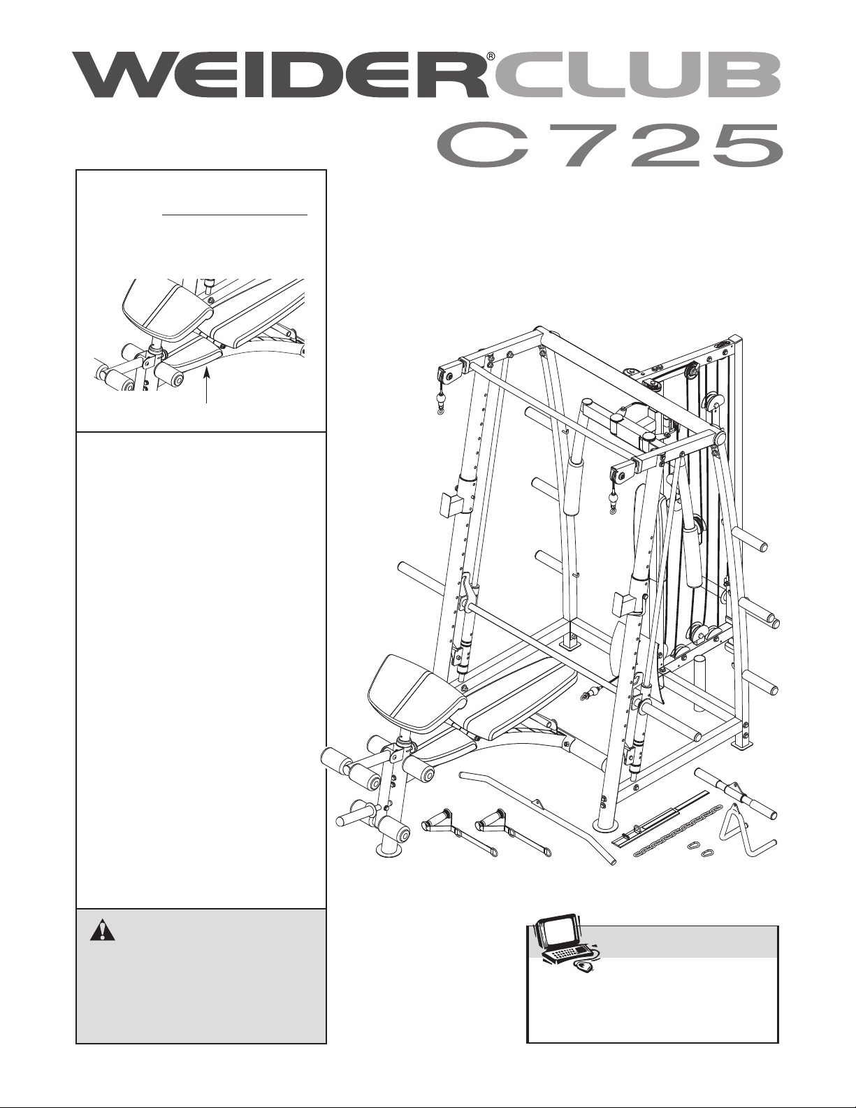
V
Serial No.
Write the serial number in the
space above for future reference.
Serial Number Decal (under seat)
QUESTIONS?
As a manufacturer, we are committed to providing complete customer satisfaction. If you have
questions, or if parts are missing,
PLEASE DO NOT CONTACT
THE STORE; please contact
Customer Care.
IMPORTANT: You must note the
product model number and
serial number (see the drawing
above) before contacting us:
CALL TOLL-FREE:
USER’S MANUAL
1-877-992-5999
Mon.–Fri. 6 a.m.–6 p.m. MST
Sat. 8 a.m.–4 p.m. MST
ON THE WEB:
www.weiderservice.com
CAUTION
Read all precautions and instructions in this manual before using
this equipment. Save this manual
for future reference.
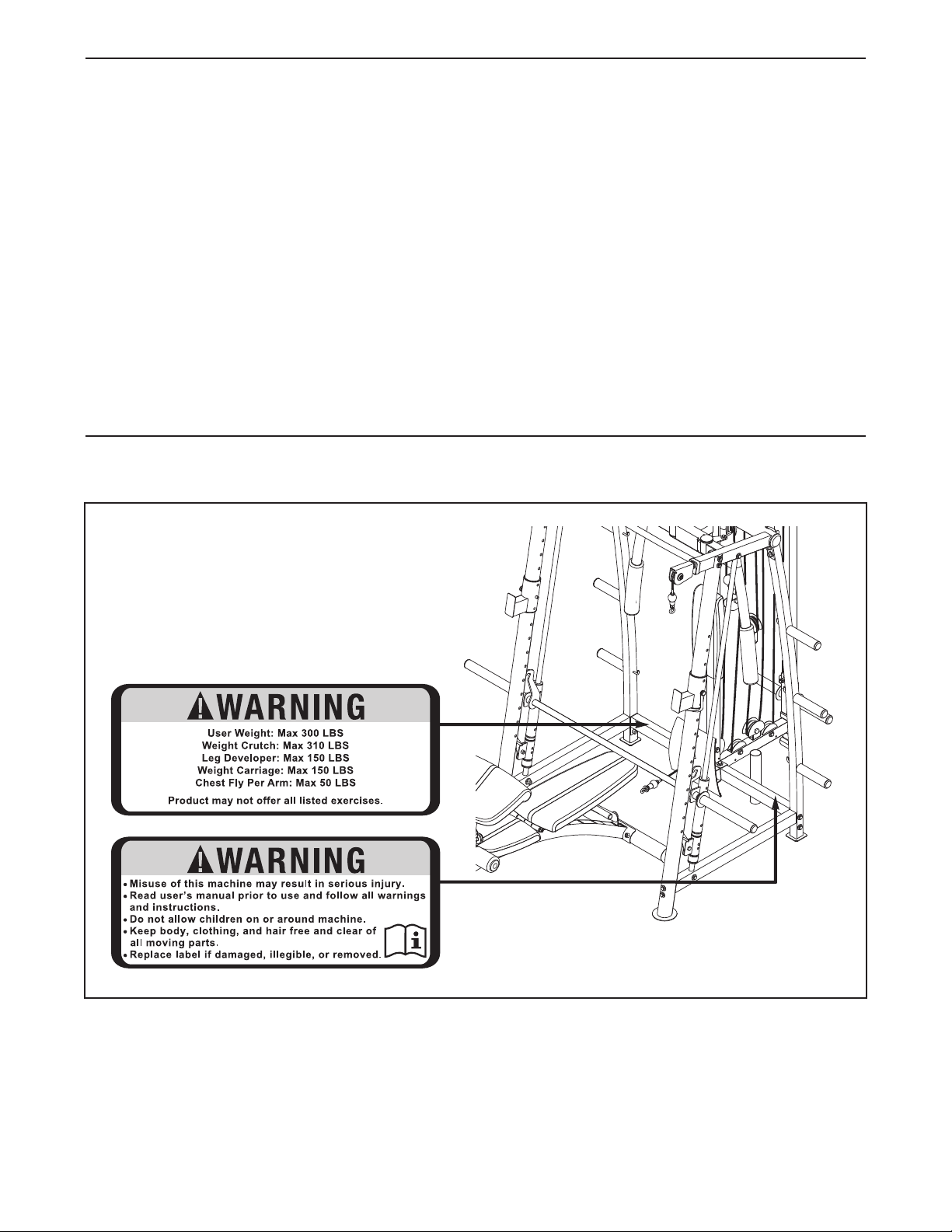
TABLE OF CONTENTS
ARNING DECAL PLACEMENT . . . . . . . . . . . . . . . . . . . . . . . . . . . . . . . . . . . . . . . . . . . . . . . . . . . . . . . . . . . . . 2
W
MPORTANT PRECAUTIONS . . . . . . . . . . . . . . . . . . . . . . . . . . . . . . . . . . . . . . . . . . . . . . . . . . . . . . . . . . . . . . . . 3
I
BEFORE YOU BEGIN . . . . . . . . . . . . . . . . . . . . . . . . . . . . . . . . . . . . . . . . . . . . . . . . . . . . . . . . . . . . . . . . . . . . . . 4
PART IDENTIFICATION CHART . . . . . . . . . . . . . . . . . . . . . . . . . . . . . . . . . . . . . . . . . . . . . . . . . . . . . . . . . . . . . .5
ASSEMBLY . . . . . . . . . . . . . . . . . . . . . . . . . . . . . . . . . . . . . . . . . . . . . . . . . . . . . . . . . . . . . . . . . . . . . . . . . . . . . . 7
ADJUSTMENT . . . . . . . . . . . . . . . . . . . . . . . . . . . . . . . . . . . . . . . . . . . . . . . . . . . . . . . . . . . . . . . . . . . . . . . . . . .29
MAINTENANCE . . . . . . . . . . . . . . . . . . . . . . . . . . . . . . . . . . . . . . . . . . . . . . . . . . . . . . . . . . . . . . . . . . . . . . . . . .33
CABLE DIAGRAM . . . . . . . . . . . . . . . . . . . . . . . . . . . . . . . . . . . . . . . . . . . . . . . . . . . . . . . . . . . . . . . . . . . . . . . . .34
EXERCISE GUIDELINES . . . . . . . . . . . . . . . . . . . . . . . . . . . . . . . . . . . . . . . . . . . . . . . . . . . . . . . . . . . . . . . . . . 35
PART LIST . . . . . . . . . . . . . . . . . . . . . . . . . . . . . . . . . . . . . . . . . . . . . . . . . . . . . . . . . . . . . . . . . . . . . . . . . . . . . .38
EXPLODED DRAWING . . . . . . . . . . . . . . . . . . . . . . . . . . . . . . . . . . . . . . . . . . . . . . . . . . . . . . . . . . . . . . . . . . . .40
ORDERING REPLACEMENT PARTS . . . . . . . . . . . . . . . . . . . . . . . . . . . . . . . . . . . . . . . . . . . . . . . . . .Back Cover
LIMITED WARRANTY . . . . . . . . . . . . . . . . . . . . . . . . . . . . . . . . . . . . . . . . . . . . . . . . . . . . . . . . . . . . . . Back Cover
WARNING DECAL PLACEMENT
The decals shown here have been applied in
the locations shown. If a decal is missing or
illegible, call the telephone number on the
front cover of this manual and request a free
replacement decal. Apply the decal in the
location shown. Note: The decals may not be
shown at actual size.
WEIDER is a registered trademark of ICON IP
2
, Inc.

IMPORTANT PRECAUTIONS
WARNING: To reduce the risk of serious injury, read all important precautions and
nstructions in this manual and all warnings on the weight bench before using the weight bench.
i
ICON assumes no responsibility for personal injury or property damage sustained by or through
the use of this product.
1. Before beginning any exercise program, consult your physician. This is especially important for persons over the age of 35 or persons with pre-existing health problems.
2. Use the weight bench only as described in
this manual.
3. It is the responsibility of the owner to ensure
that all users of the weight bench are ade
quately informed of all precautions.
4. The weight bench is intended for home use
only. Do not use the weight bench in a commercial, rental, or institutional setting.
5.
Keep the weight
moisture and dust. Place the weight
on a level surface, with a mat beneath it to
protect the floor or carpet. Make sure that
there is enough clearance around the weight
bench
6. Keep children under age 12 and pets away
from the weight bench at all times.
7.
Inspect and properly tighten all parts regularly. Replace any worn parts immediately.
Make sure that the pins and knobs are fully
8.
engaged before the weight bench is used.
to mount, dismount, and use it.
bench
indoors, away from
-
bench
The weight bench is designed to support a
10.
maximum user weight of 300 lbs. (136 kg)
and a maximum total weight of 610 lbs. (277
kg). Do not place more than 310 lbs. (141 kg),
including the free weight bar, on the weight
rests. Do not place more than 150 lbs. (68 kg)
on the leg lever. Do not place more than 150
lbs. (68 kg) on the weight carriage. Do not
place more than 310 lbs. (141kg) on the barbell.
11. Make sure that the cables remain on the pulleys at all times. If the cables bind while you
are exercising, stop immediately and make
sure that the cables are on the pulleys.
Replace all cables at least every two years.
12. Always set all the weight rests and safety
spotters at the same height.
13. Always place an equal amount of weight on
each side of the weight carriage or barbell.
Always exercise with a partner. Your partner
14.
should be ready to catch the barbell if you
cannot complete a repetition.
15. Always disconnect the lat bar when performing an exercise that does not require the lat
bar.
9.
Wear appropriate clothes while exercising.
Always wear athletic shoes for foot protection while exercising.
16.
If you feel pain or dizziness while exercising,
stop immediately and cool down.
3
BEFORE YOU BEGIN
hank you for selecting the versatile WEIDER
T
C725 weight bench. The weight bench offers an
impressive selection of exercise stations designed to
develop every major muscle group of the body.
Whether your goal is to tone your body, build dramatic
uscle size and strength, or improve your cardiovas-
m
cular system, the weight bench will help you to
achieve the specific results you want.
For your benefit, read this manual carefully before
using the weight bench. If you have questions after
reading this manual, please see the front cover of this
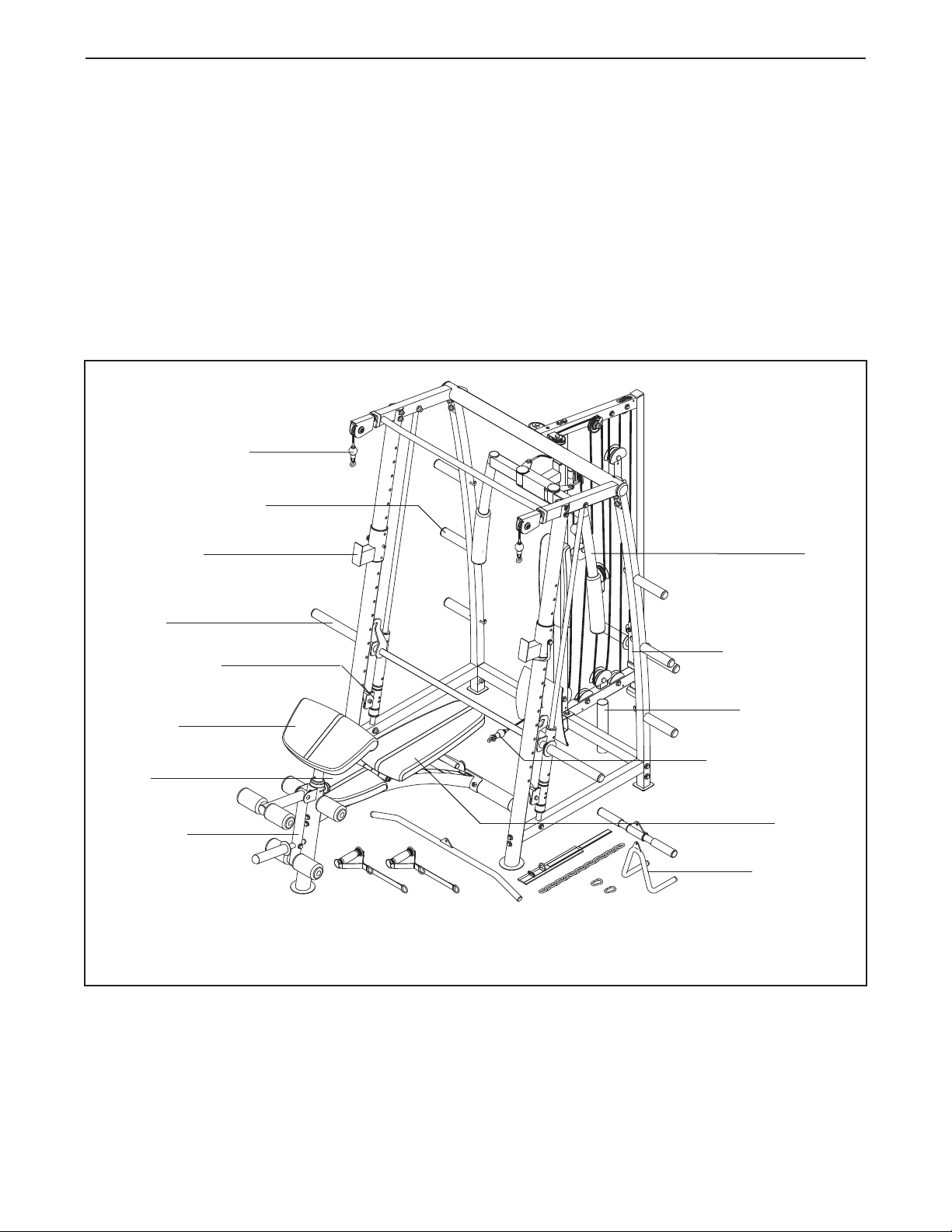
High Pulley Station
Weight Storage Tube
Weight Rest
®
LUB
C
anual. To help us assist you, note the product model
m
number and serial number before contacting us. The
model number and the location of the serial number
decal are shown on the front cover of this manual.
o avoid a registration fee for any service needed
T
under warranty, you must register the weight bench
at www.weiderservice.com/registration.
Before reading further, please review the drawing below
and familiarize yourself with the parts that are labeled.
Assembled Dimensions:
Height: 84 in. (214 cm)
Width: 85 in. (215 cm)
Depth: 100 in. (254 cm)
Wt.: 308 lbs. (140 kg)
Arm
Right Side
Barbell
Barbell Spotter
Curl Pad
Seat
Leg Lever
Note: The terms “right side” and “left side” are determined relative to a person sitting with his
back to the backrest; they do not correspond to right and left on the drawings in the manual.
Left Side
Weight Carriage
Free Weight Bar
Storage Tube
Low Pulley Station
Backrest
Accessories
4
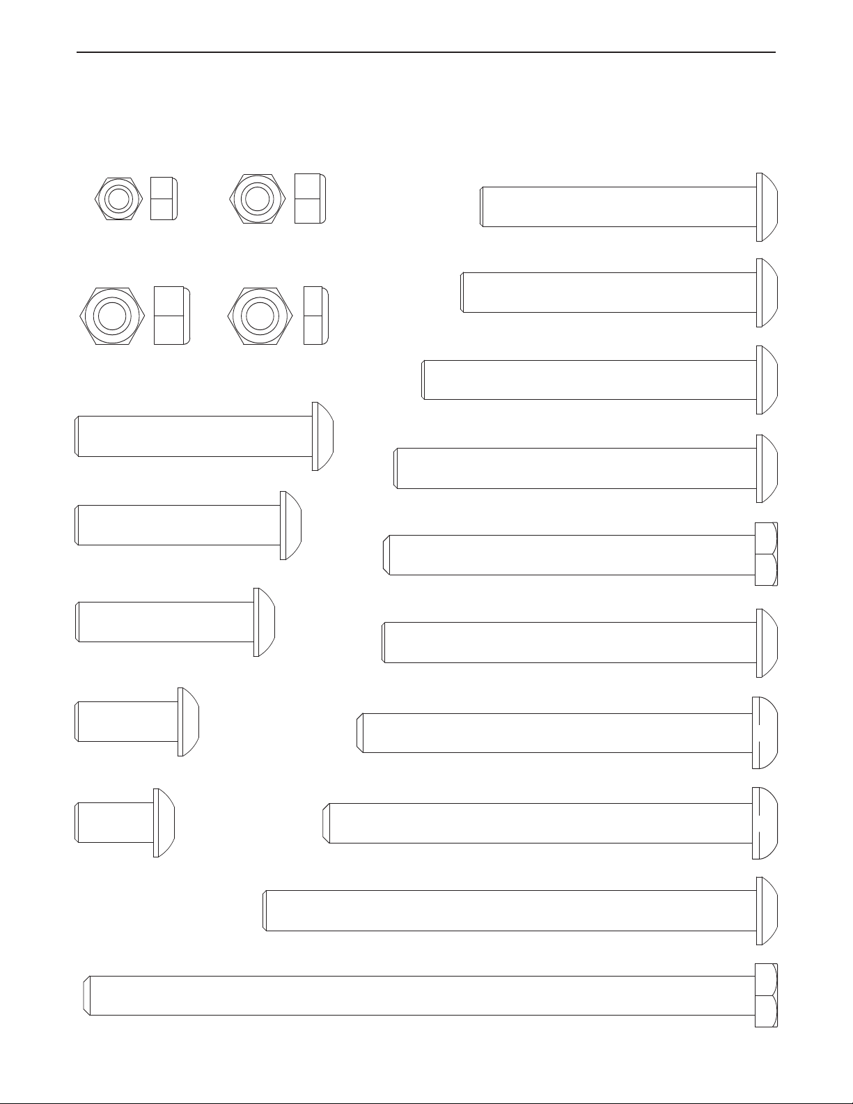
M8 Nylon
Locknut (139)
M10 x 95mm Button Bolt (144)
M10 x 85mm Button Bolt (125)
M10 x 170mm Bolt (123)
M10 x 100mm Button Screw (129)
M10 x 110mm Button Screw (117)
M10 x 94mm Bolt (134)
M10 x 92mm Button Bolt (120)
M10 x 52mm Button Bolt (135)
M10 x 60mm Button Bolt (136)
M10 x 26mm Button Bolt (119)
M10 x 45mm Button Bolt (131)
M10 x 75mm Button Bolt (130)
M10 x 125mm Button Bolt (141)
M10 x 20mm
Button Bolt (56)
M10 x 70mm Button Bolt (97)
M10 Nylon
Locknut (116)
M10 Thin Nylon
Locknut (86)
M6 Nylon
Locknut (150)
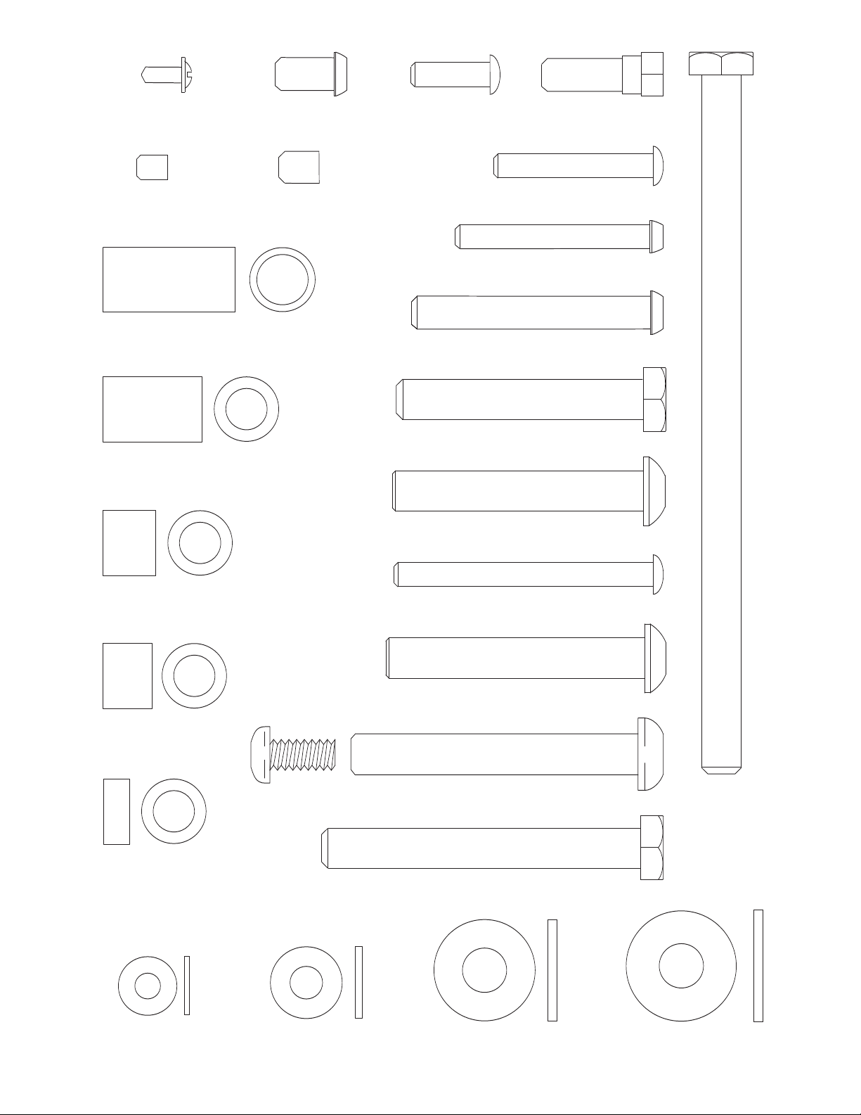
PART IDENTIFICATION CHART
See the drawings below to identify small parts used in assembly. The number in parentheses by each drawing is
the key number of the part, from the PART LIST near the end of this manual. Note: Some small parts may
have been preattached. If a part is not in the parts bag, check to see if it has been preattached.
5
M6 Washer (142)
M8 Washer (84)
M8 x 15mm
B
utton Screw (112)
M4 x 10mm Self-
tapping Screw (79)
M6 x 8mm
Set Screw (99)
M8 x 60mm Button Bolt (95)
M8 x 25mm
Shoulder Bolt (143)
M10 Washer (83)
M10 Large Washer (39)
M
6 x 20mm
Screw (122)
M
8 x 10mm
Set Screw (49)
M6 x 40mm Screw (140)
M6 x 65mm Button Screw (126)
M10 x 175mm Bolt (42)
M10 x 65mm Button Bolt (66)
M10 x 63mm Button Bolt (133)
M10 x 70mm Bolt Set (118)
M10 x 62mm Bolt (96)
M10 x 80mm Bolt (147)
M6 x 48mm Button Bolt (124)
33mm
Spacer (52)
25mm
Spacer (121)
6.5mm
Spacer (100)
13mm
Spacer (108)
12.5mm
Spacer (138)
6

ASSEMBLY
ake Assembly Easier
M
verything in this manual is designed to ensure
E
that the weight bench can be assembled successfully by almost anyone. By setting aside
plenty of time, assembly will go smoothly.
Before beginning assembly, carefully read the following information and instructions:
• To hire an authorized service technician to
assemble the weight bench, call 1-800-445-2480.
• Assembly requires two persons. Some steps may
require three persons.
• Because of its size, the weight bench should be
assembled in the location where it will be used.
Make sure that there is enough clearance to walk
around the weight bench as you assemble it.
• Place all parts in a cleared area and remove the
packing materials. Do not dispose of the packing
materials until assembly is completed.
• For help identifying small parts, use the PART
IDENTIFICATION CHART on pages 5 and 6.
• As you assemble the weight bench, make sure all
parts are oriented as shown in the drawings.
• Tighten all parts as you assemble them, unless
instructed to do otherwise.
• In addition to the included tools, assembly
requires the following tools (not included):
two adjustable wrenches
one rubber mallet
one standard screwdriver
one Phillips screwdriver
Assembly will be more convenient if you have a
socket set, a set of open-end or closed-end
wrenches, or a set of ratchet wrenches.
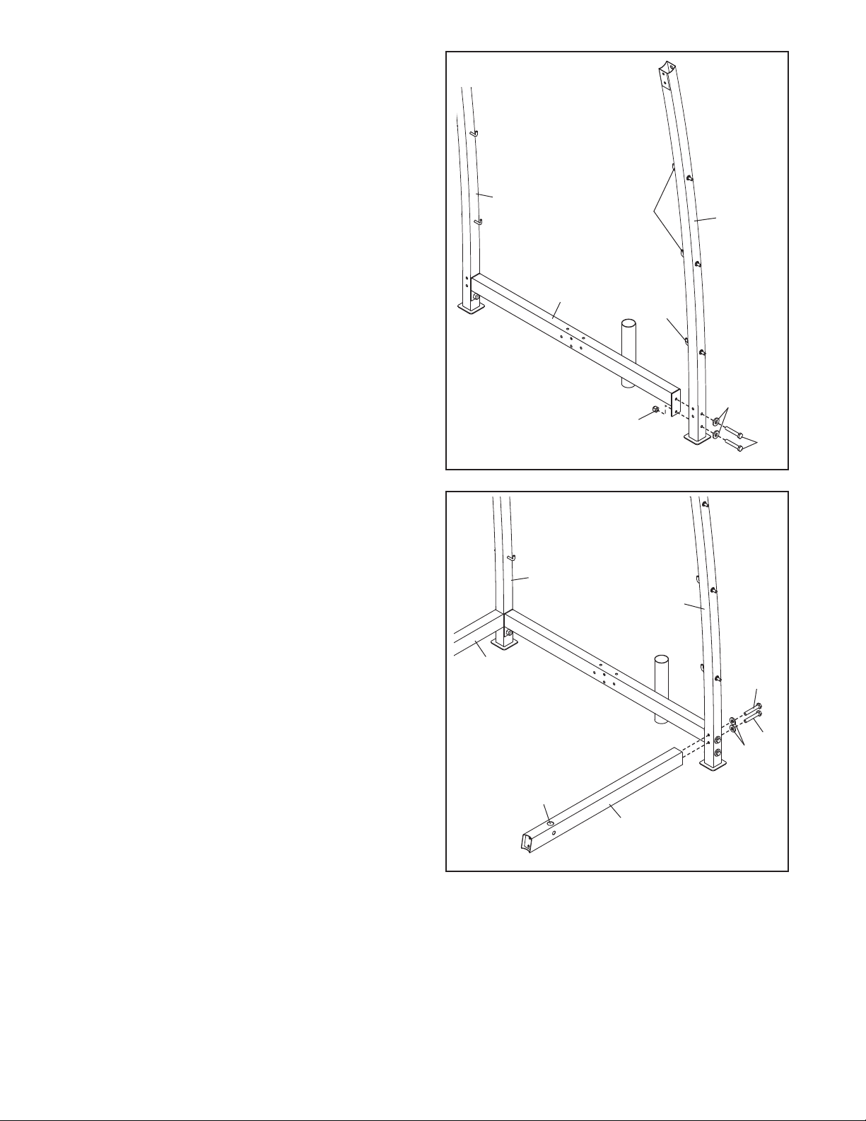
1.
Before beginning assembly, read the important information in the box above. See the
PART IDENTIFICATION CHART on pages 5
and 6 for help identifying small parts.
Note: Remove all hex keys from the hardware
kit for the rack.
Attach the Rear Stabilizer (2) to the Bench
Frame (1) with two M10 x 95mm Bolts (144), two
M10 Washers (83), and two M10 Nylon Locknuts
Do not tighten the Nylon Locknuts yet.
(116).
1
116
1
16
1
2
83
144
7
2. Attach the Seat (33) to the Bench Frame (1) with
four M6 x 20mm Screws (122).
2
33
1
3. Attach the Front Leg (3) to the Bench Frame (1)
with two M10 x 110mm Screws (117) and two M10
Washers (83).
See step 1. Tighten the M10 Nylon Locknuts
(116).
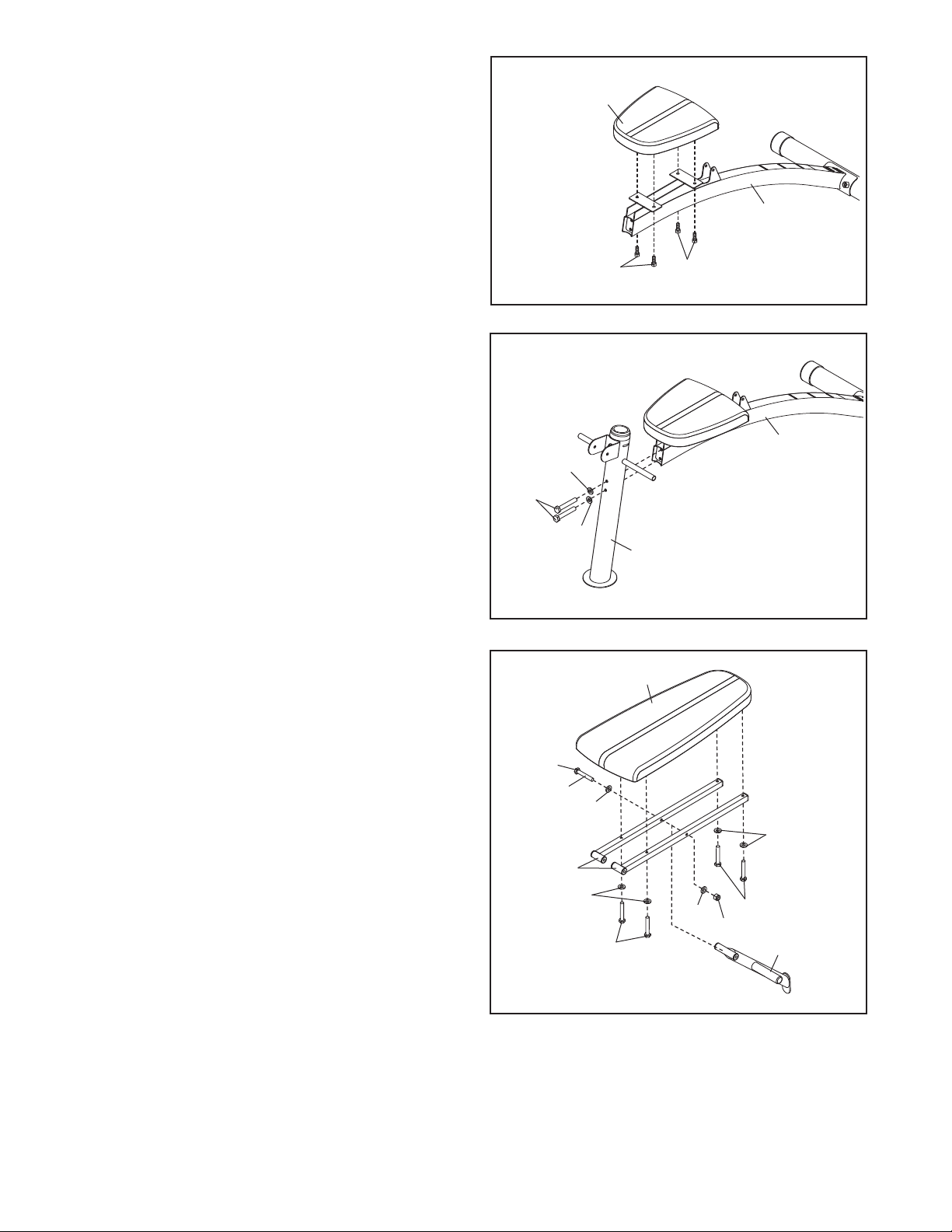
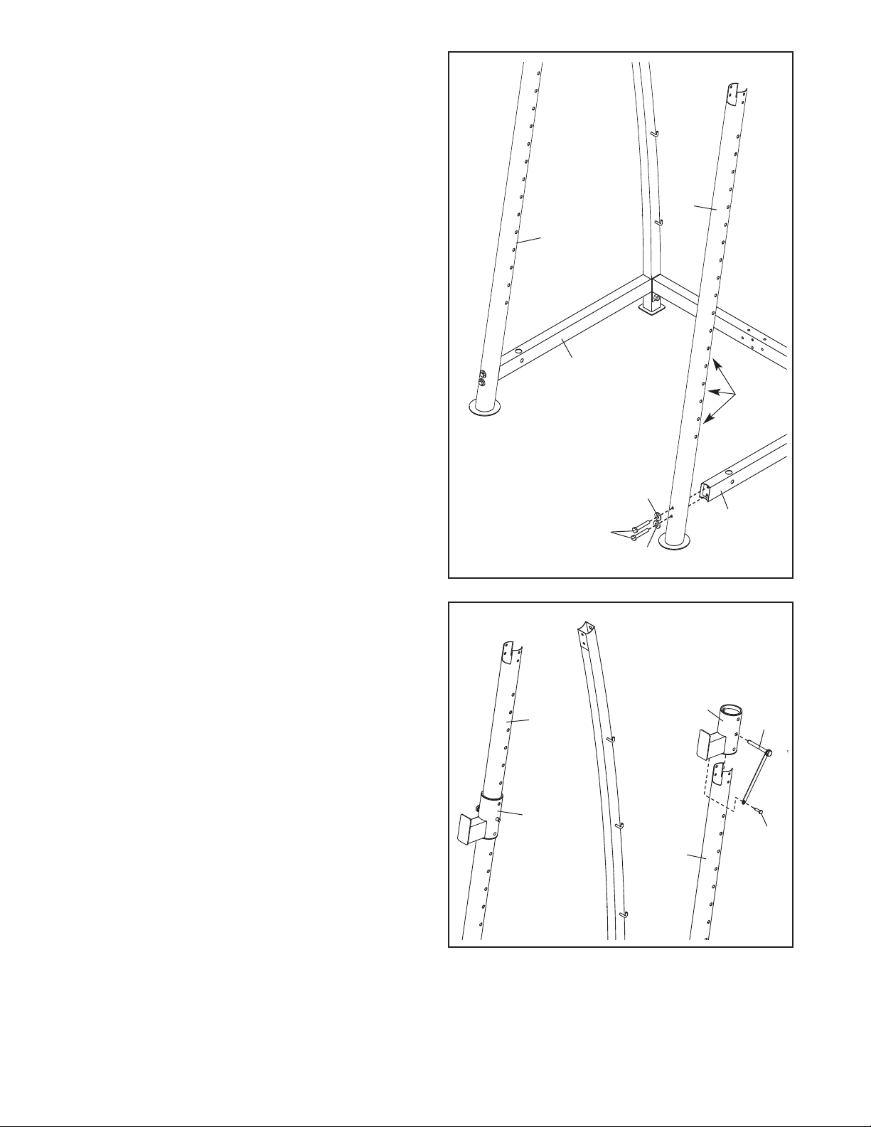
4. Apply some of the included grease to an M10 x
170mm Bolt (123). Attach the Backrest Post (7) to
the Backrest Frames (8) with the Bolt, two M10
Washers (83), and an M10 Nylon Locknut (116).
Do not tighten the Nylon Locknut yet.
122
3
83
117
83
4
122
1
3
32
Next, attach the Backrest (32) to the Backrest
Frames (8) with four M6 x 40mm Screws (140)
and four M6 Washers (142).
Screws yet.
Do not tighten the
123
Grease
83
142
8
142
83
140
140
116
7
8
5. Apply grease to an M10 x 175mm Bolt (42).
Attach the Backrest Frames (8) to the Bench
rame (1) with the Bolt, two M10 Washers (83), a
F
33mm Spacer (52), and an M10 Nylon Locknut
116). Set the end of the Backrest Post (7) in one
(
of the slots in the Bench Frame. Do not over-
tighten the Nylon Locknut; the Backrest
Frames must pivot easily.
See step 4. Tighten the M10 Nylon Locknut
(116) and the four M6 x 40mm Screws (140). Do
not overtighten the Nylon Locknut; the
Backrest Post (7) must pivot easily.
5
Grease
42
83
8
83
52
116
1
7
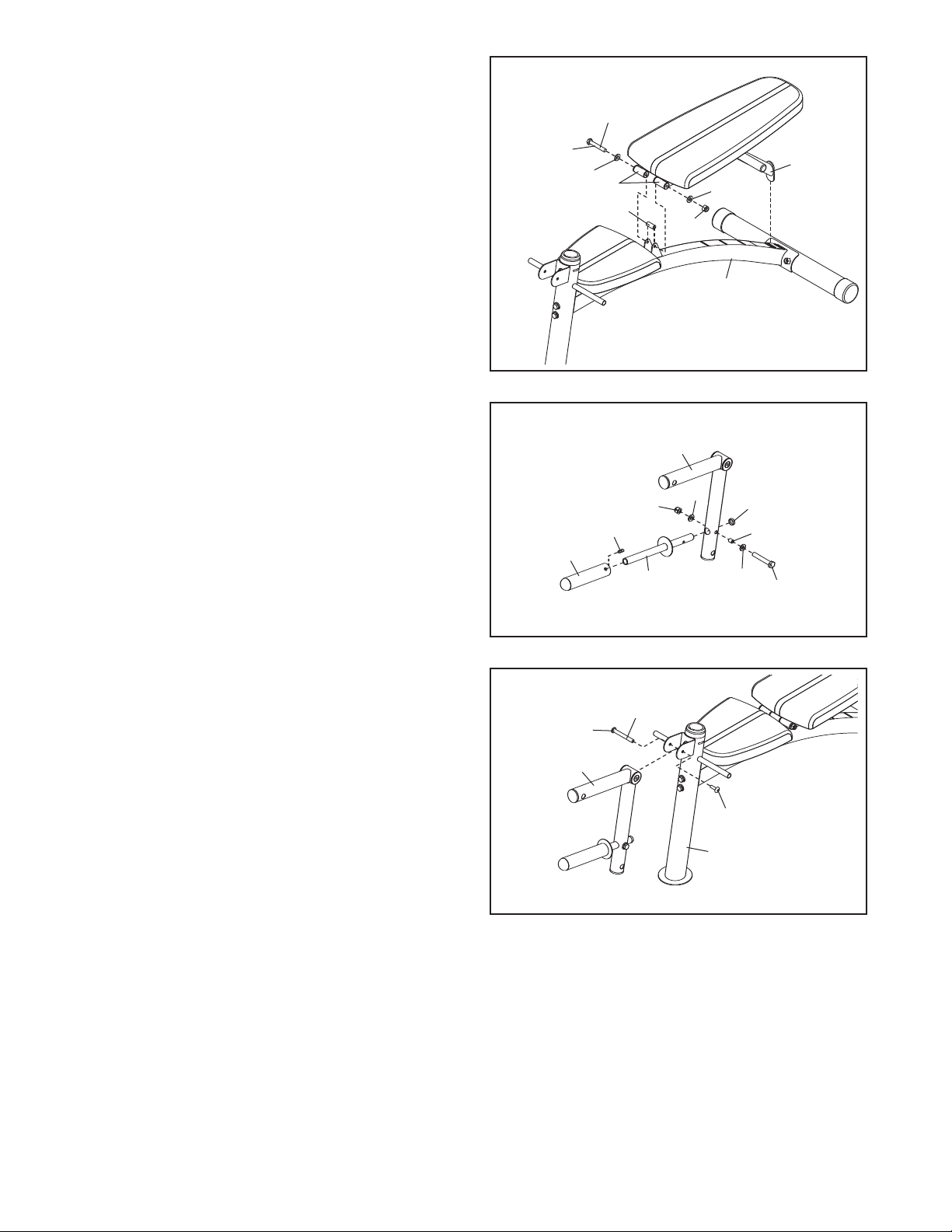
6. Attach the Weight Tube (5) to the Leg Lever (4)
with an M8 x 60mm Button Bolt (95), two M8
Washers (84), a 12.5mm Spacer (138), and an M8
Nylon Locknut (139).
is inside the Leg Lever.
Next, press a 25mm Round Outer Cap (45) onto
the indicated end of the Weight Tube (5). Then,
slide the Olympic Adapter (46) onto the Weight
Tube. Attach the Olympic Adapter with an M8 x
10mm Set Screw (49).
7. Apply grease to the barrel of an M10 x 70mm Bolt
Set (118). Attach the Leg Lever (4) to the Front
Leg (3) with the Bolt Set.
barrel of the Bolt Set is inserted through both
sides of the bracket on the Front Leg.
Make sure that the Spacer
Make sure that the
6
4
139
49
46
7
Grease
118
4
84
5
3
118
84
45
138
95
9
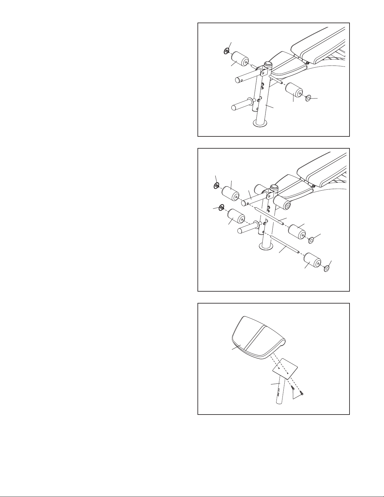
8. Slide two Foam Pads (35) onto the Front Leg (3).
Then, press two Pad Caps (37) into the Foam
ads.
P
8
37
35
37
35
3
9. Insert the two Pad Tubes (51) into the Leg Lever
(4). Slide two Foam Pads (35) onto each Pad
ube. Then, press a Pad Cap (37) into each
T
Foam Pad.
10. Attach the Curl Pad (34) to the Curl Post (10) with
two M6 x 20mm Screws (122).
9
10
37
37
35
35
4
51
35
37
51
35
37
10
34
10
122
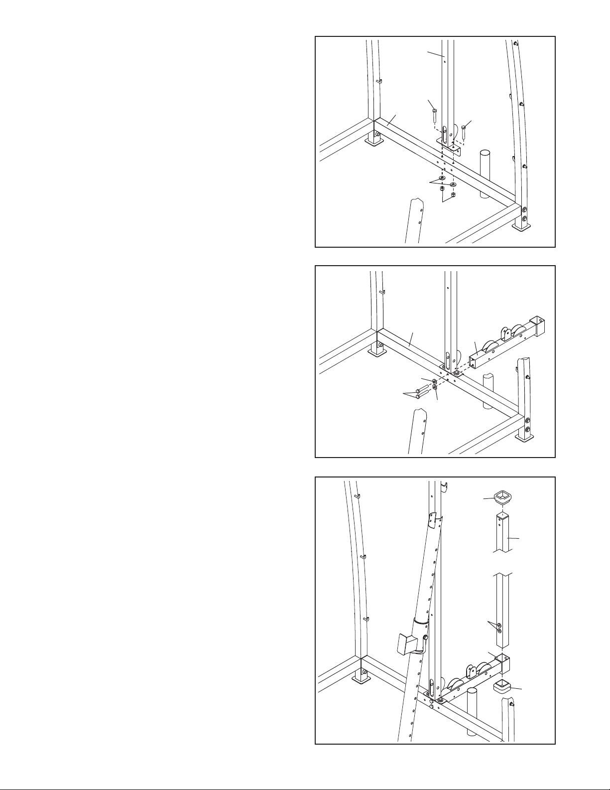
11. Identify the Left Rear Upright (12) by looking at
the locations of the hooks. Orient the Left Rear
pright as shown, and attach it to the Rear Base
U
(9) with two M10 x 70mm Button Bolts (97), two
10 Washers (83), and an M10 Nylon Locknut
M
(116). Do not tighten the Button Bolts or the
Nylon Locknut yet.
11
Attach the Right Rear Upright (60) to the Rear
Base (9) in the same way.
12. Orient one of the Side Bases (14) so that the indicated hole is on top. Attach the Side Base to the
Left Rear Upright (12) with two M10 x 85mm
Button Bolts (125) and two M10 Washers (83).
Do not tighten the Button Bolts yet.
Attach the other Side Base (14) to the Right
Rear Upright (60) in the same way.
12
60
60
Hooks
9
Hook
116
12
12
83
97
14
125
125
83
Hole
14
11
13. Orient one of the Front Uprights (11) so that the
lots are on the indicated side. Attach the Front
s
Upright to the left Side Base (14) with two M10 x
00mm Button Screws (129) and two M10
1
Washers (83).
Attach the other Front Upright (11) to the right
ide Base (14) in the same way.
S
3
1
11
11
14
Slots
14. Attach an Upright Pin/Tether (28) to one of the
Weight Rests (26) with an M4 x 10mm Self-tapping Screw (79).
Orient the Weight Rest (26) as shown, and slide it
onto the left Front Upright (11). Fully insert the
Upright Pin (28) into the Weight Rest and one of
the holes in the Front Upright.
Attach the other W
Front Upright (1
eight Rest (26) to the right
1) in the same way
.
14
26
11
83
14
129
83
26
28
79
11
12
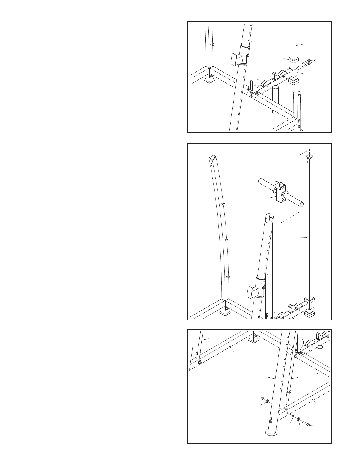
15. Orient the Center Upright (13) as shown. Attach
the Center Upright to the Rear Base (9) with two
10 x 85mm Button Bolts (125), two M10
M
Washers (83), and two M10 Nylon locknuts (116).
o not Tighten the Nylon Locknuts yet.
D
15
3
1
125
9
83
116
125
16. Attach the Weight Carriage Base (20) to the Rear
Base (9) with two M10 x 75mm Button Bolts (130)
and two M10 Washers (83). Do not tighten the
Button Bolts yet.
17. Orient the Weight Bumper (30) as shown, and
slide it downward onto the Weight Carriage
Upright (21).
Next, orient the Weight Carriage Upright (21) as
shown, and insert it into the Weight Carriage
Base (20). Then, press the Upright Foot (29) onto
the Weight Carriage Upright.
16
9
20
83
130
83
17
30
21
13
elded
W
Washers
20
29
18. Press the Weight Bumper (30) down onto the
eight Carriage Base (20).
W
18
ext, attach the Weight Carriage Upright (21) to
N
the Weight Carriage Base (20) with two M10 x
85mm Button Bolts (125). Do not tighten the
Button Bolts yet.
19. Orient the Weight Carriage (19) as shown, and
slide it onto the Weight Carriage Upright (21).
19
19
30
21
2
125
0
Insert one of the Barbell Guides (25) into the left
20.
Side Base (14).
M10 x 65mm Button Bolt (66), two M10 Washers
(83), a 13mm Spacer (108), and an M10 Nylon
Locknut (116).
Attach the other Barbell Guide (25) to the right
Side Base (14) in the same way
Attach the Barbell Guide with an
.
20
25
14
21
11
16
1
83
25
14
14
108
83
66
 Loading...