

Weider 831159832 Owner’s Manual
Model No, 831.159832
Serial No.
The serial number is found in the
location shown below. Write the
serial number in the space above.
USER'S MANUAL
>ni_y I L
EXEF_CI_E
EQUIPMENT
HELPLINE!
1-800-736-6S79
Serial
_ Number
Decal
SEARS, ROEBUCK AND CO.
HOFFMAN ESTATES, IL 60179
CAUTION
Read all precautions and instruc-
tions in this manual before using
this equipment. Save this manu-
al for future reference,
Patent Pending
www.weiderfitness.com
new products, prizes,
fitness tips, and much morel
TABLE OF CONTENTS
IMPORTANT PRECAUTIONS ............................................................. 3
BEFORE YOU BEGIN ................................................................... 4
ASSEMBLY ........................................................................... 5
ADJUSTMENTS ...................................................................... 25
WEIGHT RESISTANCE CHART .......................................................... 27
TROUBLESHOOTING AND MAINTENANCE ................................................ 28
CABLE DIAGRAMS ................................................................... 30
ORDERING REPLACEMENT PARTS ............................................... Back Cover
FULL 90 DAY WARRANTY ....................................................... Back Cover
Note: A PART LIST/EXPLODED DRAWING and a PART IDENTIFICATION CHART are attached in the center of
this manual. Remove the PART LIST/EXPLODED DRAWING and the PART IDENTIFICATION CHART before
beginning assembly.
2
IMPORTANT PRECAUTIONS
WARNING: To reduce the risk of serious injury, read the following important precautions
before using the weight system.
1. Read all instructions in this manual and in
the accompanying literature before using the
weight system.
2. It is the responsibility of the owner to ensure
that all users of the weight system are ade-
quately informed of all precautions.
3. The weight system is intended for home use
only. Do not use the weight system in any
commercial, rental, or institutional setting.
4. Use the weight system only on a level sur-
face. Cover the floor beneath the weight sys-
tem to protect the floor.
5. Make sure all parts are properly tightened
each time you use the weight system.
Replace any worn parts immediately.
6; Keep children under 12 and pets away from
the weight system at all times.
7. Keep hands and feet away from moving parts.
8; Always wear athletic shoes for foot protection.
9. The weight system is designed to support a
a maximum user weight of 250 pounds.
10. Always stand on the foot plate when per-
forming an exercise that could cause the
weight system to tip.
11. Never release the press arm, butterfly arms,
leg lever, press plate, lat bar, ab strap, or
nylon strap while weights are raised; the
weights will fall with great force.
12. Always disconnect the lat bar from the
weight system when performing an exercise
that does not use the lat bar.
13. Make sure that the cables remain on the pul-
leys at all times. If the cables bind while you
are exercising, stop immediatelY and make
sure that the cables are on all of the pulleys.
14. If you feel pain or dizziness at any time while
exercising, stop immediately and begin cool-
ing down.
15. The decal shown here
has been placed on the
weight system in the
location shown on page
4. If the decal is missing
or illegible, please call
our toll-free HELPLINE at
the number on the front
cover of this manual to
order a replacement
decal. Apply the new
decal in the indicated
location.
orremoved.
WARNING: Before beginning this or any exercise program, consult your physician. This
is especially important for persons over the age of 35 or persons with pre-existing health problems.
Read all instructions before using. SEARS assumes no responsibility for personal injury or property
damage sustained by or through the use of this product.
3
BEFORE YOU BEGIN
Thank you for selecting the innovative and versatile
WELDER®PRO POWER STACK weight system. The
POWER STACK offers a unique selection of weight
stations designed to develop every major muscle
group of the body. Whether your goal is to tone your
body, build dramatic muscle size and strength, or
improve your cardiovascular system, the POWER
STACK will help you to achieve the results you want.
For your benefit, read this manual carefully before
using the POWER STACK weight system. If you
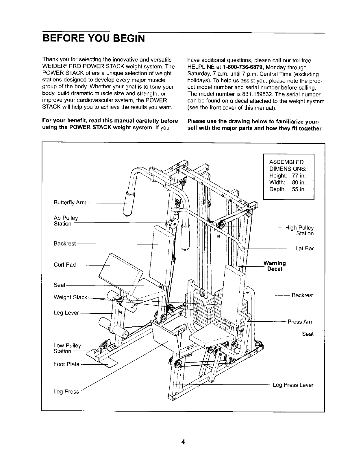
Butterfly Arm
Ab Pulley
Station
Backrest
have additional questions, please call our toll-free
HELPLINE at 1-800-736-6879, Monday through
Saturday, 7 a.m. until 7 p.m. Central Time (excluding
holidays). To help us assist you, please note the prod-
uct model number and serial number before calling.
The model number is 831.159832. The serial number
can be found on a decal attached to the weight system
(see the front cover of this manual).
Please use the drawing below to familiarize your-
self with the major parts and how they fit together.
ASSEMBLED
DIMENSIONS:
Height: 77 in.
Width: 80 in.
Depth: 55 in.
High Pulley
Station
Lat Bar
Curl Pad
Seat.
Weig
Leg Lever
Low Pulley
Foot Plate
Leg Press
Warning
-- Decal
Backrest
Press Arm
Seat
Leg Press Lever
4
ASSEMBLY
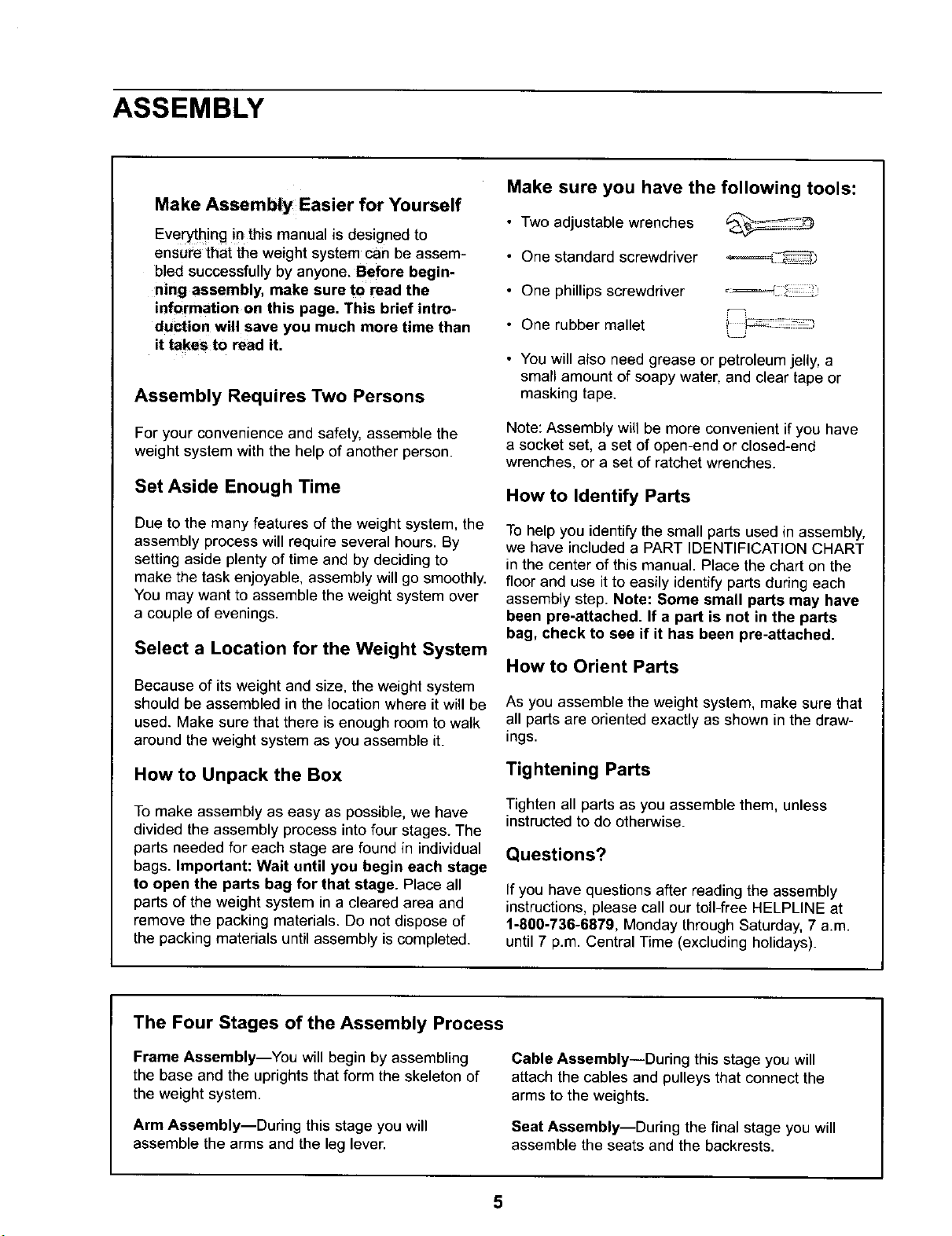
Make Assembly Easier for Yourself
Everything in this manual is designed to
ensure that the weight system can be assem-
bled successfully by anyone. Before begin-
ning assembly, make sure to read the
information on this page. This brief intro-
duction will save you much more time than
it takes to read it,
Assembly Requires Two Persons
Make sure you have the following tools:
• Two adjustable wrenches
• One standard screwdriver _=_,-_
• One phillips screwdriver
• One rubber mallet
• You will also need grease or petroleum jelly, a
small amount of soapy water, and clear tape or
masking tape.
For your convenience and safety, assemble the
weight system with the help of another person.
Set Aside Enough Time
Due to the many features of the weight system, the
assembly process will require several hours. By
setting aside plenty of time and by deciding to
make the task enjoyable, assembly will go smoothly.
You may want to assemble the weight system over
a couple of evenings.
Select a Location for the Weight System
Because of its weight and size, the weight system
should be assembled in the location where it will be
used. Make sure that there is enough room to walk
around the weight system as you assemble it.
How to Unpack the Box
To make assembly as easy as possible, we have
divided the assembly process into four stages. The
parts needed for each stage are found in individual
bags. Important: Wait until you begin each stage
to open the parts bag for that stage. Place all
parts of the weight system in a cleared area and
remove the packing materials. Do not dispose of
the packing materials untilassembly is completed.
Note: Assembly will be more convenient if you have
a socket set, a set of open-end or closed-end
wrenches, or a set of ratchet wrenches.
How to Identify Parts
To help you identify the small parts used in assembly,
we have included a PART IDENTIFICATION CHART
in the center of this manual. Place the chart on the
floor and use it to easily identify parts during each
assembly step. Note: Some small parts may have
been pre-attached. If a part is not in the parts
bag, check to see if it has been pre-attached.
How to Orient Parts
As you assemble the weight system, make sure that
all parts are oriented exactly as shown in the draw-
ings.
Tightening Parts
Tighten all parts as you assemble them, unless
instructed to do otherwise.
Questions?
If you have questions after reading the assembly
instructions, please call our toll-free HELPLINE at
1-800-736-6879, Monday through Saturday, 7 a.m.
until 7 p.m. Central Time (excluding holidays).
The Four Stages of the Assembly Process
Frame Assembly--You will begin by assembling
the base and the uprights that form the skeleton of
the weight system.
Arm Assembly--During this stage you will
assemble the arms and the leg lever.
Cable Assembly--During this stage you will
attach the cables and pulleys that connect the
arms to the weights.
Seat Assembly--During the final stage you will
assemble the seats and the backrests.
5
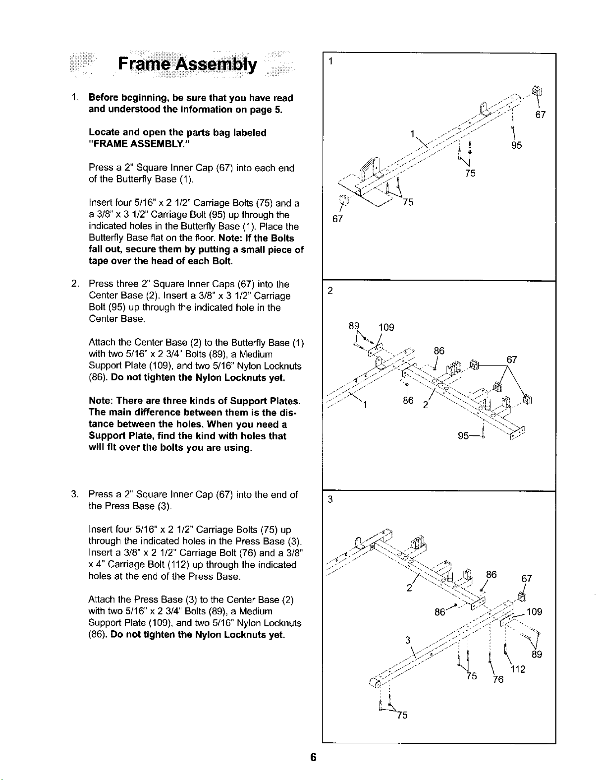
1. Before beginning, be sure that you have read
and understood the information on page 5.
67
Locate and open the parts bag labeled
"FRAME ASSEMBLY."
Press a 2" Square inner Cap (67) into each end
of the Butterfly Base (1).
insert four 5116" x 2 1/2" Carriage Botts (75) and a
a 3/8" x 3 1/2" Carriage Bolt (95) up through the
indicated holes in the Butterfly Base (1). Place the
Butterfly Base fiat on the floor. Note: If the Bolts
fall out, secure them by putting a small piece of
tape over the head of each Bolt.
2. Press three 2" Square Inner Caps (67) into the
Center Base (2). Insert a 3/8" x 3 1/2" Carriage
Bolt (95) up through the indicated hole in the
Center Base.
Attach the Center Base (2) to the Butterfly Base (1)
with two 5/16" x 2 3/4" Bolts (89), a Medium
Support Plate (109), and two 5/16" Nylon Locknuts
(86). Do not tighten the Nylon Locknuts yet.
Note: There are three kinds of Support Plates.
The main difference between them is the dis-
tance between the holes. When you need a
Support Plate, find the kind with holes that
will fit over the bolts you are using,
1
\
67
2
89
109
86
67
.
Press a 2" Square Inner Cap (67) into the end of
the Press Base (3).
Insert four 5/16" x 2 1/2" Carriage Bolts (75) up
through the indicated holes in the Press Base (3).
Insert a 3/8" x 2 1/2" Carriage Bolt (76) and a 3/8"
x 4" Carriage Bolt (112) up through the indicated
holes at the end of the Press Base.
Attach the Press Base (3) to the Center Base (2)
with two 5/16" x 2 3/4" Bolts (89), a Medium
Support Plate (109), and two 5/16" Nylon Locknuts
(86). Do not tighten the Nylon Locknuts yet.
3
6
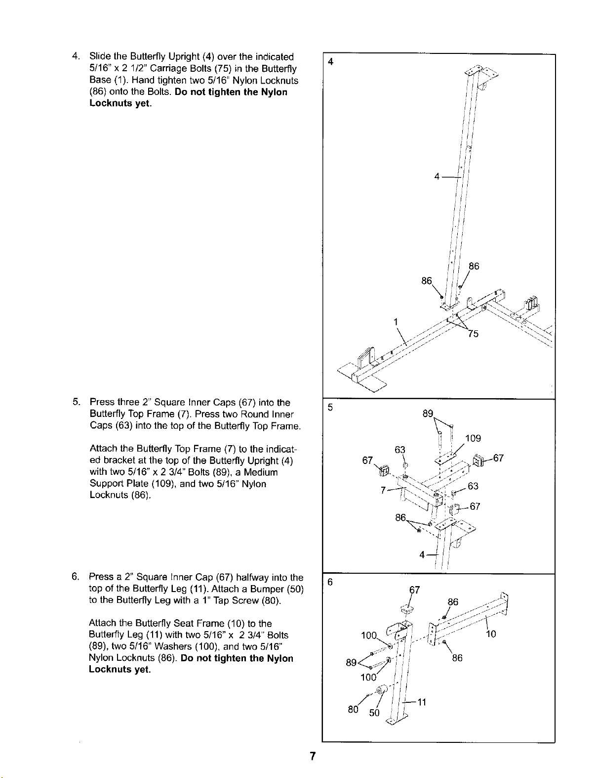
Slide the Butterfly Upright (4) over the indicated
4. 4
5/16" x 2 1/2" Carriage Bolts (75) in the Butterfly
Base (1). Hand tighten two 5/16" Nylon Locknuts
(86) onto the Bolts. Do not tighten the Nylon
Locknuts yet.
! I :1
86
86
5,
Press three 2" Square Inner Caps (67) into the
Butterfly Top Frame (7). Press two Round Inner
Caps (63) into the top of the Butterfly Top Frame.
Attach the Butterfly Top Frame (7) to the indicat-
ed bracket at the top of the Butterfly Upright (4)
with two 5/16" x 2 3/4" Bolts (89), a Medium
Support Plate (109), and two 5/16" Nylon
Locknuts (86).
6. Press a 2" Square Inner Cap (67) halfway into the
top of the Butterfly Leg (11). Attach a Bumper (50)
to the Butterfly Leg with a 1" Tap Screw (80).
Attach the Butterfly Seat Frame (10) to the
Butterfly Leg (11) with two 5/16" x 2 3/4" Bolts
(89), two 5/16" Washers (100), and two 5/16"
Nylon Locknuts (86). Do not tighten the Nylon
Locknuts yet.
89
109
63
67 !
,_j./67
.63
6
67
86
.... 10
86
7
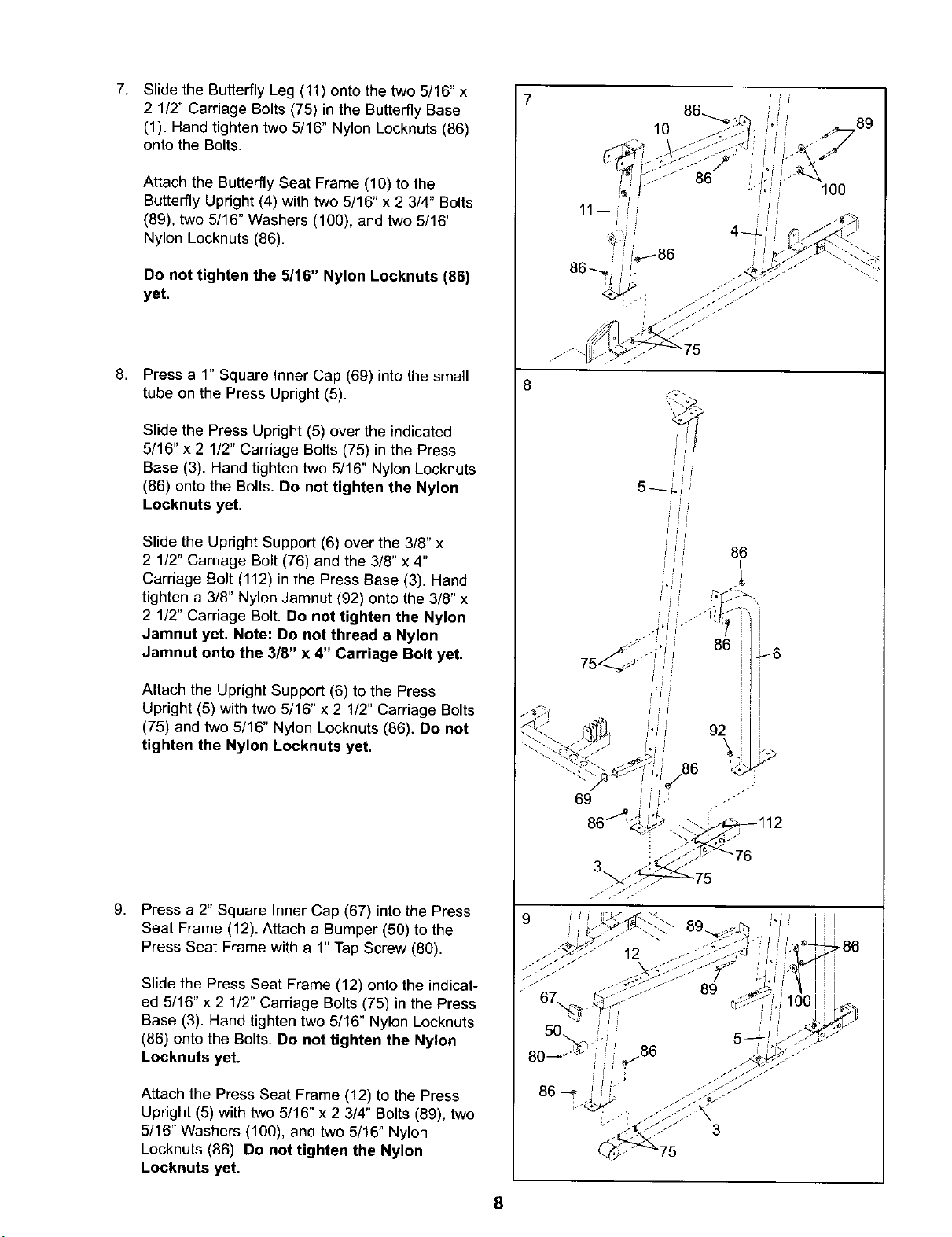
7. Slide the Butterfly Leg (11) onto the two 5/16" x
2 1/2" Carriage Bolts (75) in the Butterfly Base
(1). Hand tighten two 5/16" Nylon Locknuts (86)
onto the Bolts.
10
Attach the Butterfly Seat Frame (10) to the
Butterfly Upright (4) with two 5/16" x 2 3/4" Bolts
(89), two 5/16" Washers (100), and two 5/16"
Nylon Locknuts (86).
Do not tighten the 5/16" Nylon Locknuts (86)
yet.
8.
Press a 1" Square Inner Cap (69) into the small
tube on the Press Upright (5).
Slide the Press Upright (5) over the indicated
5/16" x 2 1/2" Carriage Bolts (75) in the Press
Base (3). Hand tighten two 5/16" Nylon Locknuts
(86) onto the Bolts. Do not tighten the Nylon
Locknuts yet.
Slide the Upright Support (6) over the 3/8" x
2 1/2" Carriage Bolt (76) and the 3/8" x 4"
Carriage Bolt (112) in the Press Base (3). Hand
tighten a 3/8" Nylon Jamnut (92) onto the 3/8" x
2 1/2" Carriage Bolt. Do not tighten the Nylon
Jamnut yet. Note: Do not thread a Nylon
Jamnut onto the 3/8" x 4" Carriage Bolt yet.
100
8
i J
= i i:
sfl
! 1=iI
, 86
1
J: I=
86 _6
Attach the Upright Support (6) to the Press
Upright (5) with two 5/16" x 2 1/2" Carriage Bolts
(75) and two 5/16" Nylon Locknuts (86). Do not
tighten the Nylon Locknuts yet.
g,
Press a 2" Square Inner Cap (67) into the Press
Seat Frame (12). Attach a Bumper (50) to the
Press Seat Frame with a 1" Tap Screw (80).
Slide the Press Seat Frame (12) onto the indicat-
ed 5/16" x 2 1/2" Carriage Bolts (75) in the Press
Base (3). Hand tighten two 5/16" Nylon Locknuts
(86) onto the Bolts. Do not tighten the Nylon
Locknuts yet.
Attach the Press Seat Frame (12) to the Press
Upright (5) with two 5/16" x 2 3/4" Bolts (89), two
5/16" Washers (100), and two 5/16" Nylon
Locknuts (86). Do not tighten the Nylon
Locknuts yet.
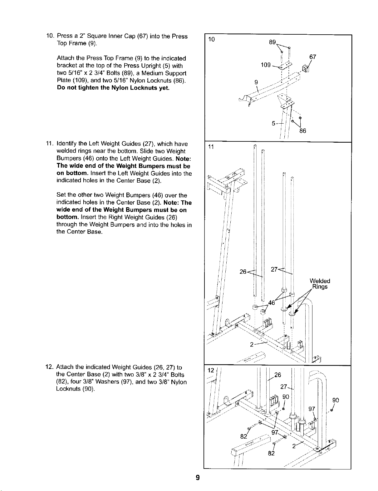
10.Pressa2"SquareInnerCap(67)intothePress
TopFrame(9).
AttachthePressTopFrame(9)totheindicated
bracketatthetopofthePressUpright(5)with
two5/16"x23/4"Bolts(89),aMediumSupport
Plate(109),andtwo5/16"NylonLocknuts(86).
Do not tighten the Nylon Locknuts yet.
10
i i 86
11. Identify the Left Weight Guides (27), which have
welded rings near the bottom. Slide two Weight
Bumpers (46) onto the Left Weight Guides. Note:
The wide end of the Weight Bumpers must be
on bottom. Insert the Left Weight Guides into the
indicated holes in the Center Base (2).
Set the other two Weight Bumpers (46) over the
indicated holes in the Center Base (2). Note: The
wide end of the Weight Bumpers must be on
bottom. Insert the Right Weight Guides (26)
through the Weight Bumpers and into the holes in
the Center Base.
11
ii
J_
26< 27"<
i i Welded
ii Rings
,,_ j j
12. Attach the indicated Weight Guides (26, 27) to
the Center Base (2) with two 3/8" x 2 3/4" Bolts
(82), four 3/8" Washers (97), and two 3/8" Nylon
Locknuts (90).
9O
J
9
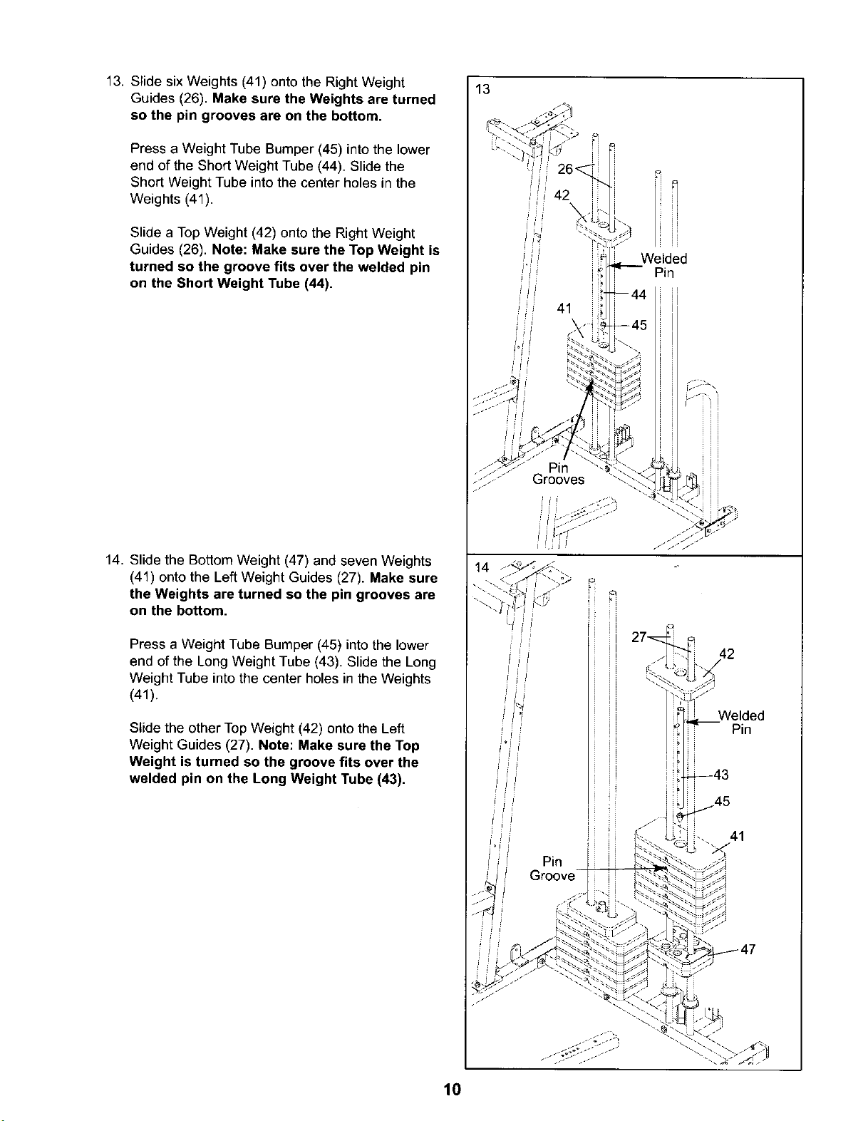
13. Slide six Weights (41) onto the Right Weight
Guides (26). Make sure the Weights are turned
so the pin grooves are on the bottom.
Press a Weight Tube Bumper (45) into the lower
end of the Short Weight Tube (44). Slide the
Short Weight Tube into the center holes in the
Weights (41).
Slide a Top Weight (42) onto the Right Weight
Guides (26). Note: Make sure the Top Weight is
turned so the groove fits over the welded pin
on the Short Weight Tube (44).
13
n
Welded
Pin
41
Pin
Grooves
14. Slide the Bottom Weight (47) and seven Weights
(41) onto the Left Weight Guides (27). Make sure
the Weights are turned so the pin grooves are
on the bottom.
Press a Weight Tube Bumper (45) into the lower
end of the Long Weight Tube (43). Slide the Long
Weight Tube into the center holes in the Weights
(41).
Slide the other Top Weight (42) onto the Left
Weight Guides (27). Note: Make sure the Top
Weight is turned so the groove fits over the
welded pin on the Long Weight Tube (43).
27
Welded
Pin
I
41
Pin
10
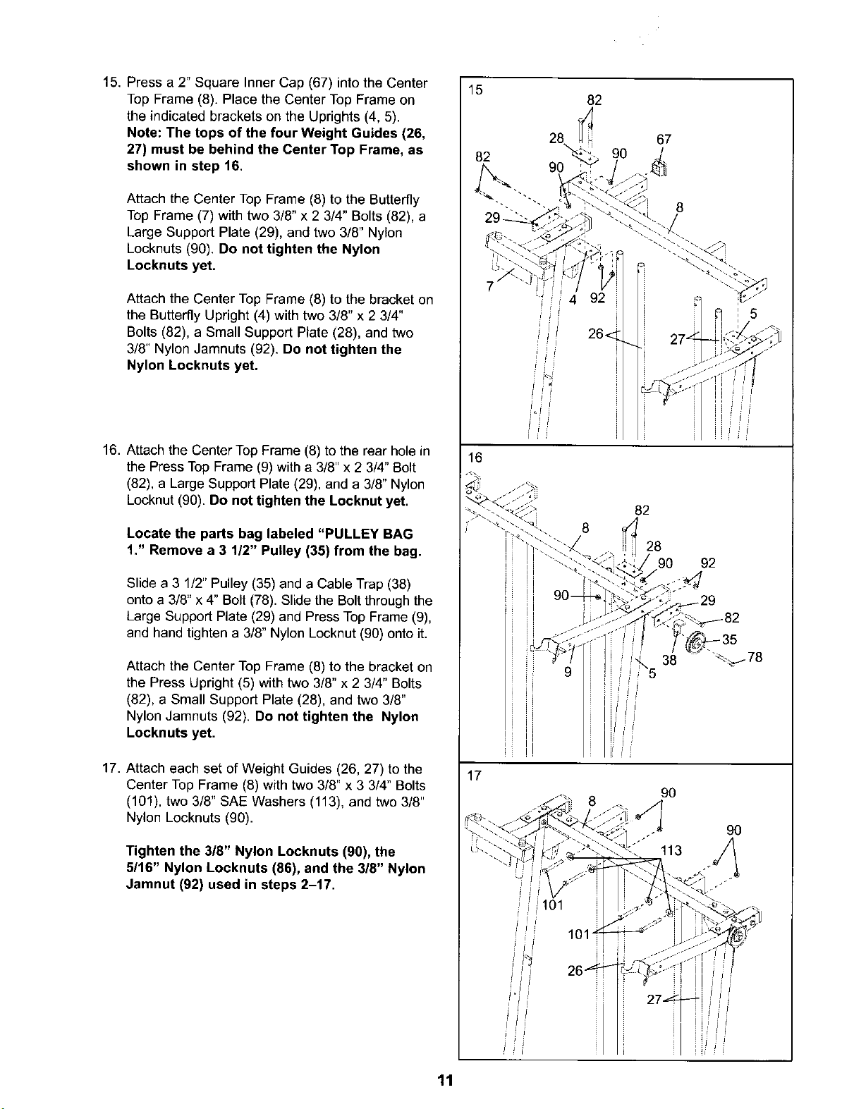
15. Press a 2" Square Inner Cap (67) into the Center
Top Frame (8). Place the Center Top Frame on
the indicated brackets on the Uprights (4, 5).
Note: The tops of the four Weight Guides (26,
27) must be behind the Center Top Frame, as
shown in step 16.
Attach the Center Top Frame (8) to the Butterfly
Top Frame (7) with two 3/8" x 2 3/4" Bolts (82), a
Large Support Plate (29), and two 3/8" Nylon
Locknuts (90). Do not tighten the Nylon
Locknuts yet.
Attach the Center Top Frame (8) to the bracket on
the Butterfly Upright (4) with two 3/8" x 2 3/4"
Bolts (82), a Small Support Plate (28), and two
3/8" Nylon Jamnuts (92). Do not tighten the
Nylon Locknuts yet.
15
82
82
28 67
9O
16. Attach the Center Top Frame (8) to the rear hole in
the Press Top Frame (9) with a 3/8" x 2 3/4" Bolt
(82), a Large Support Plate (29), and a 3/8" Nylon
Locknut (90). Do not tighten the Locknut yet.
Locate the parts bag labeled "PULLEY BAG
1," Remove a 3 1/2" Pulley (35) from the bag.
Slide a 3 1/2" Pulley (35) and a Cable Trap (38)
onto a 3/8" x 4" Bolt (78). Slide the Bolt through the
Large Support Plate (29) and Press Top Frame (9),
and hand tighten a 3/8" Nylon Locknut (90) onto it.
Attach the Center Top Frame (8) to the bracket on
the Press Upright (5) with two 3/8" x 2 3/4" Bolts
(82), a Small Support Plate (28), and two 3/8"
Nylon Jamnuts (92). Do not tighten the Nylon
Locknuts yet.
17. Attach each set of Weight Guides (26, 27) to the
Center Top Frame (8) with two 3/8" x 3 3/4" Bolts
(101), two 3/8" SAE Washers (113), and two 3/8"
Nylon Locknuts (90).
Tighten the 3/8" Nylon Locknuts (90), the
5/16" Nylon Locknuts (86), and the 318" Nylon
Jamnut (92) used in steps 2-17.
16
82
8
28
9O 92
i
38
17
9O
90
113
i i
!i'1,
11
101"
......... . .............. iiiiiiiiii i
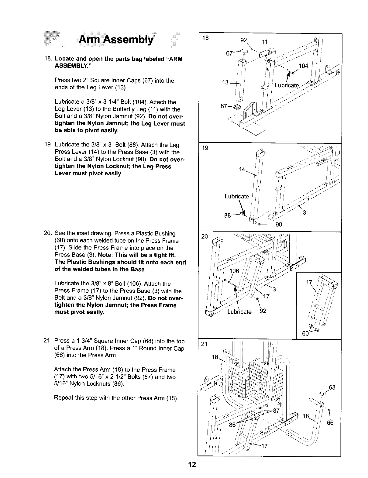
18. Locate and open the parts bag labeled "ARM
ASSEMBLY."
Press two 2" Square Inner Caps (67) intothe
ends of the Leg Lever (13).
Lubricate a 3/8" x 3 1/4" Bolt (104). Attach the
Leg Lever (13) to the Butterfly Leg (11) with the
Bolt and a 3/8" Nylon Jamnut (92). Do not over-
tighten the Nylon Jamnut; the Leg Lever must
be able to pivot easily.
Assembly
18
19. Lubricate the 3/8" x 3" Bolt (88). Attach the Leg
Press Lever (14) to the Press Base (3) with the
Bolt and a 3/8" Nylon Locknut (90). Do not over-
tighten the Nylon Locknut; the Leg Press
Lever must pivot easily.
20. See the inset drawing. Press a Plastic Bushing
(60) onto each welded tube on the Press Frame
(17). Slide the Press Frame into place on the
Press Base (3). Note: This will be a tight fit.
The Plastic Bushings should fit onto each end
of the welded tubes in the Base.
Lubricatethe 3/8" x 8" Bolt (106). Attach the
Press Frame (17) to the Press Base (3) with the
Bolt and a 3/8" Nylon Jamnut (92). Do not over-
tighten the Nylon Jamnut; the Press Frame
must pivot easily.
19
3
r
_ Lubricate 92
21. Press a 1 3/4" Square Inner Cap (68) into the top
of a Press Arm (18). Press a 1" Round Inner Cap
(66) into the Press Arm.
Attach the Press Arm (18) to the Press Frame
(17) with two 5/16" x 2 1/2" Bolts (87) and two
5/16" Nylon Locknuts (86).
Repeat this step with the other Press Arm (18).
21
68
12
 Loading...