

Weider 831154030 Owner’s Manual
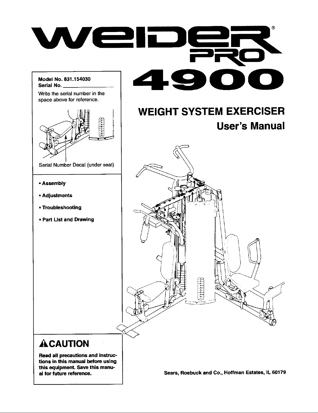
Model No. 831.154030
Serial No.
Writethe serial number in the
space above for reference.
Serial Number Decal (under seat)
• Assembly
• Adjustments
• Troubleshooting
• Part List and Drawing
WEIGHT SYSTEM EXERCISER
User's Manual
_I_CAUTION
Read all precautions and instruc-
tions in this manual before using
this equipment. Save this manu-
al for future reference. Sears, Roebuck and Co., Hoffman Estates, IL 60179
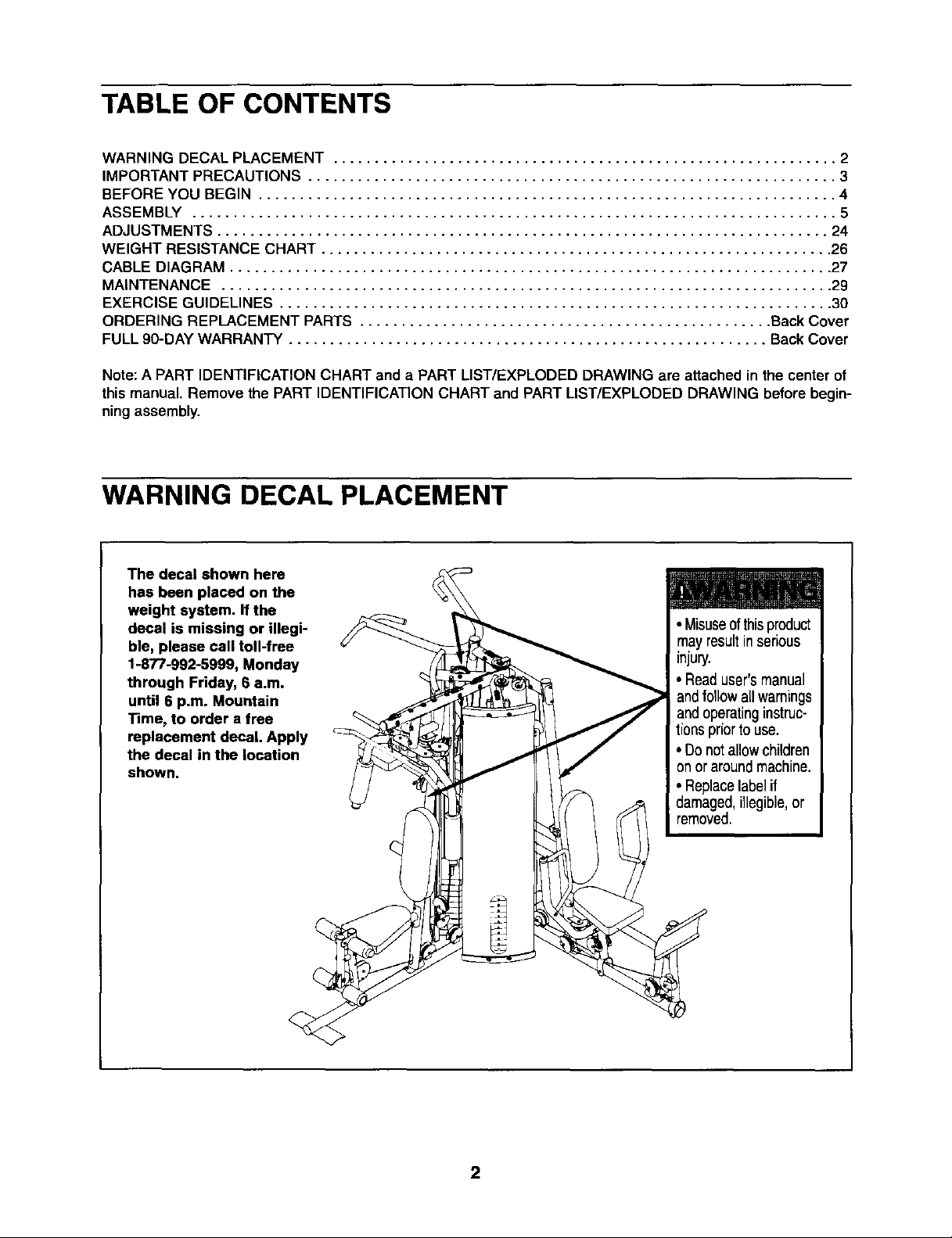
TABLE OF CONTENTS
WARNING DECAL PLACEMENT ............................................................. 2
IMPORTANT PRECAUTIONS ................................................................ 3
BEFORE YOU BEGIN ...................................................................... 4
ASSEMBLY .............................................................................. 5
ADJUSTMENTS .......................................................................... 24
WEIGHT RESISTANCE CHART .............................................................. 26
CABLE DIAGRAM ......................................................................... 27
MAINTENANCE .......................................................................... 29
EXERCISE GUIDELINES ................................................................... 30
ORDERING REPLACEMENT PARTS .................................................. Back Cover
FULL 90-DAY WARRANTY .......................................................... Back Cover
Note: A PART IDENTIFICATION CHART and a PART LIST/EXPLODED DRAWING are attached in the center of
this manual. Remove the PART IDENTIFICATION CHART and PART LIST/EXPLODED DRAWING before begin-
ning assembly.
WARNING DECAL PLACEMENT
The decal shown here
has been placed on the
weight system. If the
decal is missing or illegi-
ble, please call toll-free
1-877-992-5999, Monday
through Friday, 6 a.m.
until 6 p.m. Mountain
Time, to order a free
replacement decal. Apply
the decal in the location
shown.
2
IMPORTANT PRECAUTIONS
_WARNING: To reduce the risk of serious injury, read the following important precautions
before using the weight system.
1. Read all instructions in this manual before
using the weight system. Use the weight sys-
tem only as described in this manual.
2. It is the responsibility of the owner to ensure
that all users of the weight system are ade-
quately informed of all precautions.
3. The weight system is intended for home use
only. Do not use the weight system in any
commercial, rental, or institutional setting.
4. Use the weight system only on a level sur-
face. Cover the floor beneath the weight sys-
tem to protect the floor.
5. Make sure all parts are properly tightened
each time the weight system is used.
Replace any worn parts immediately.
6. Keep children under 12 and pets away from
the weight system at all times.
10. Make sure that the cables remain on the pul-
leys at all times. If the cables bind as you are
exercising, stop immediately and make sure
that the cables are on the pulleys. Replace all
cables at least every two years.
11.
Always secure the weight stack with the lock
pin and lock after exercising to prevent
unauthorized use of the weight system (see
LOCKING THE WEIGHT STACK on page 25).
12. Always stand on the foot plate when per-
forming an exercise that could cause the
weight system to tip.
13. Never release the arms, leg lever, lat bar, leg
press, ab strap, or handle while weights are
raised. The weights will fall with great force.
14. Always disconnect the lat bar from the
weight system when performing an exercise
that does not use the let bar.
15.
7. The weight system is designed to support a
maximum user weight of 300 pounds.
8. Always wear athletic shoes for foot protec-
tion while exercising.
9. Keep hands and feet away from moving parts.
_lk Wi'_i'tI_II[_[U" Before beginning this or any exercise program, consult your physician. This
is especially important for persons over the age of 35 or persons with pre-existing health problems.
Read all instructions before using. Sears assumes no responsibility for personal injury or property
damage sustained by or through the use of this product.
Keep the resistance system indoors, away
from moisture and dust. Do not put the
resistance system in a garage or covered
patio, or near water.
16.
If you feel pain or dizziness at any time while
exercising, stop immediately and begin cool-
ing down.
3
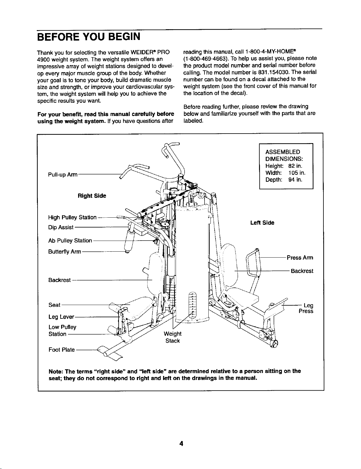
BEFORE YOU BEGIN
Thank you for selecting the versatile WELDER®PRO
4900 weight system.The weight system offers an
impressivearray of weight stationsdesigned to devel-
op every major muscle groupof the body.Whether
your goal isto tone your body, builddramatic muscle
size and strength,or improveyour cardiovascularsys-
tem, the weightsystem will help you to achieve the
specificresultsyou want.
For your benefit, read this manual carefully before
using the weight system. If you havequestionsafter
Pull-upArm
Right Side
High Pulley Station
DipAssist
readingthis manual, call 1-800-4-MY-HOME ®
(1-800-469-4663). To help us assist you, please note
the productmodel number and serial number before
calling.The model number is 831.154030. The serial
number can be found on a decal attached to the
weight system (see the frontcover of this manual for
the locationof the decal).
Before reading further, please review the drawing
belowand familiarize yourself with the parts that are
labeled.
ASSEMBLED
DIMENSIONS:
Height: 82 in.
Width: 105 in.
Depth: 94 in.
Left Side
Ab Pulley Station
ButterflyArm
Backrest
Seat
Leg Lever
Low Pulley
Station
Foot Plate
Note: The terms "right side" and "left side" are determined relative to a person sitting on the
seat; they do not correspond to right and left on the drawings in the manual.
Weight
Stack
PressArm
Backrest
Leg
Press
4
ASSEMBLY
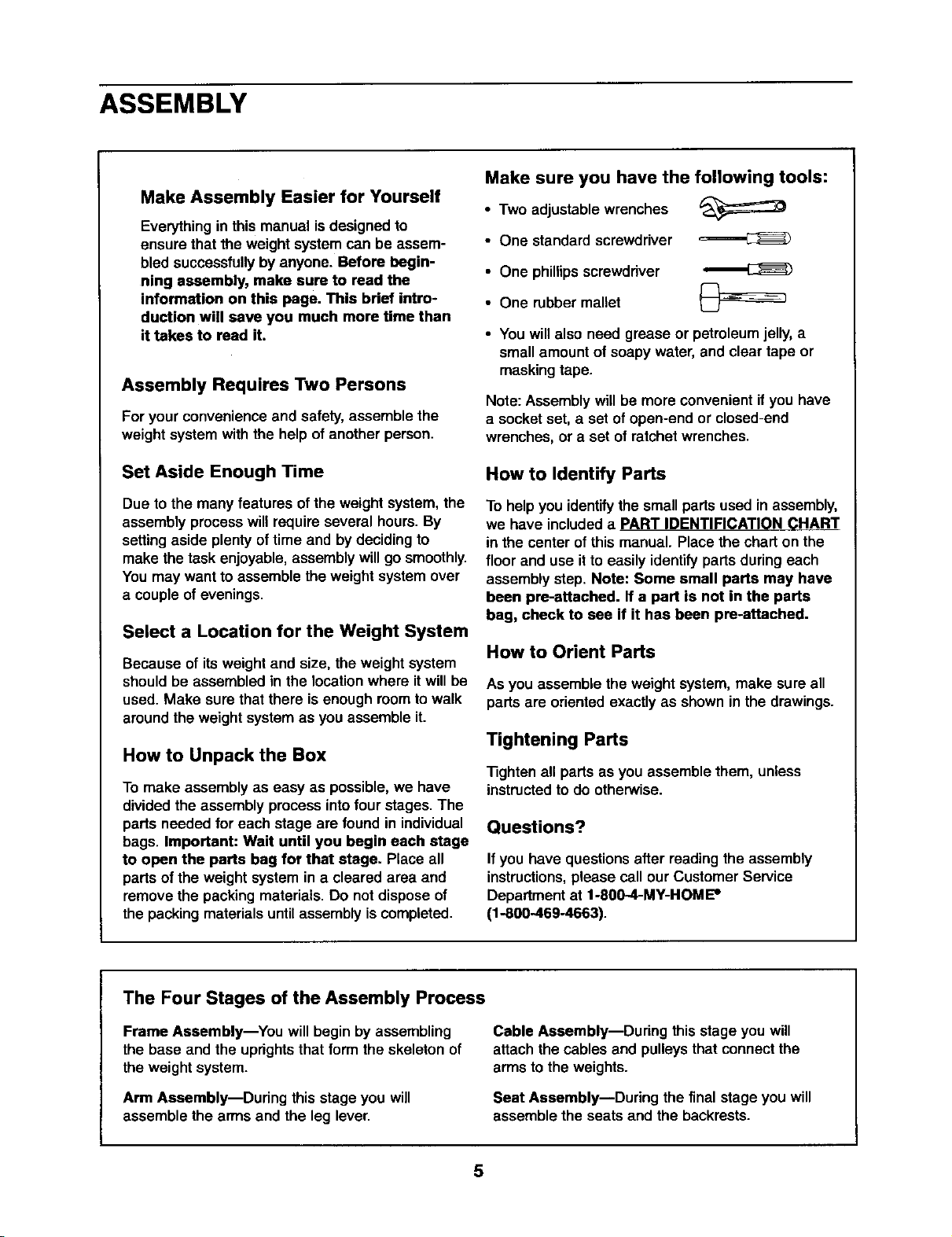
Make Assembly Easier for Yourself
Everything in this manual is designed to
ensure that the weight system can be assem-
bled successfully by anyone. Before begin-
ning assembly, make sure to read the
information on this page. This brief intro-
duction will save you much more time than
it takes to read it.
Assembly Requires Two Persons
For your convenienceand safety, assemble the
weight system withthe help of another person,
Make sure you have the following tools:
• Two adjustable wrenches
• One standard screwdriver
• One phillipsscrewdriver
• One rubbermallet
• You will also need grease or petroleumjelly,a
small amount of soapy water, and clear tape or
maskingtape.
Note: Assembly will be more convenientifyou have
a socket set, a set of open-end or closed-end
wrenches, or a set of ratchet wrenches.
Set Aside Enough Time
Due to the many features ofthe weightsystem,the
assembly processwillrequire several hours.By
setting aside plenty of time and by deciding to
make the task enjoyable, assembly will go smoothly.
You may want to assemble the weight system over
a couple of evenings.
Select a Location for the Weight System
Because of its weight and size, the weight system
shouldbe assembled in the locationwhere itwillbe
used. Make sure that there is enoughroomto walk
aroundthe weightsystem as you assemble it.
How to Unpack the Box
To make assembly as easy as possible, we have
divided the assembly processintofourstages.The
parts needed for each stage are found in individual
bags. Important: Wait until you begin each stage
to open the parts bag for that stage. Place all
parts of the weight system in a cleared area and
remove the packing materials. Do not dispose of
the packingmaterialsuntilassemblyis completed.
How to Identify Parts
To helpyou identifythe small parts used in assembly,
we have included a PART IDENTIFICATION CHART
in the center of this manual. Place the chart on the
floor and use it to easily identify parts during each
assembly step. Note: Some small parts may have
been pre-attached. If a part is not in the parts
bag, check to see if it has been pre-attached.
How to Orient Parts
As you assemble the weight system,make sure all
parts are oriented exactly as shown in the drawings.
Tightening Parts
_ghten all parts as you assemble them, unless
instructedto do otherwise.
Questions?
If you have questions after reading the assembly
instructions,please call our Customer Service
Department at 1-800-4-MY-HOME"
(1-800-469-4663).
The Four Stages of the Assembly Process
Frame Assembly--You will begin by assembling
the base and the uprights that form the skeleton of
the weightsystem.
Arm Assembly--During this stage you will
assemble the arms and the leg lever.
Cable Assembly--During this stage you will
attach the cables and pulleys that connectthe
arms to the weights.
Seat Assembly--During the final stage you will
assemble the seats and the backrests.
5
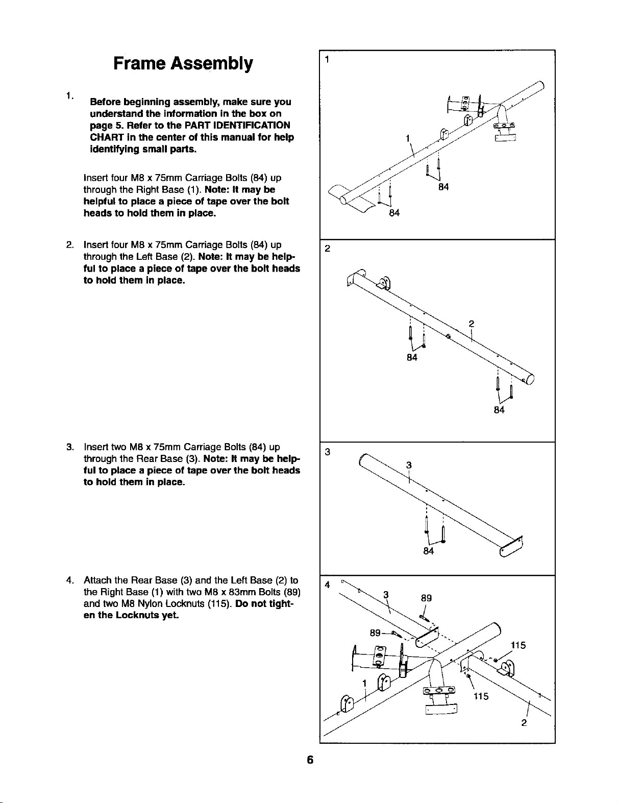
Frame Assembly 1
1.
Before beginning assembly, make sure you
understand the information inthe box on
page 5. Refer to the PART IDENTIFICATION
CHART in the center of this manual for help
identifying small parts.
Insert four M8 x 75mm Carriage Bolts(84) up
through the Right Base (1). Note: It may be
helpful to place a piece of tape over the bolt
heads to hold them in place.
2.
Insertfour M8 x 75mm Carriage Bolts (84) up
through the Left Base (2). Note: It may be help-
ful to place a piece of tape over the bolt heads
to hold them in place.
3.
Inserttwo M8 x 75mm Carriage Bolts (84) up
throughthe Rear Base (3). Note: It may be help
ful to place a piece of tape over the bolt heads
to hold them in place.
84
84
2
2
84
84
3
4.
Attachthe Rear Base (3) andthe Left Base (2) to
the Right Base (1) with two M8 x 83mm Bolts (89)
and two M8 Nylon Locknuts(115). Do not tight-
en the Locknuta yet.
84
4
3 89
115
115
2
6
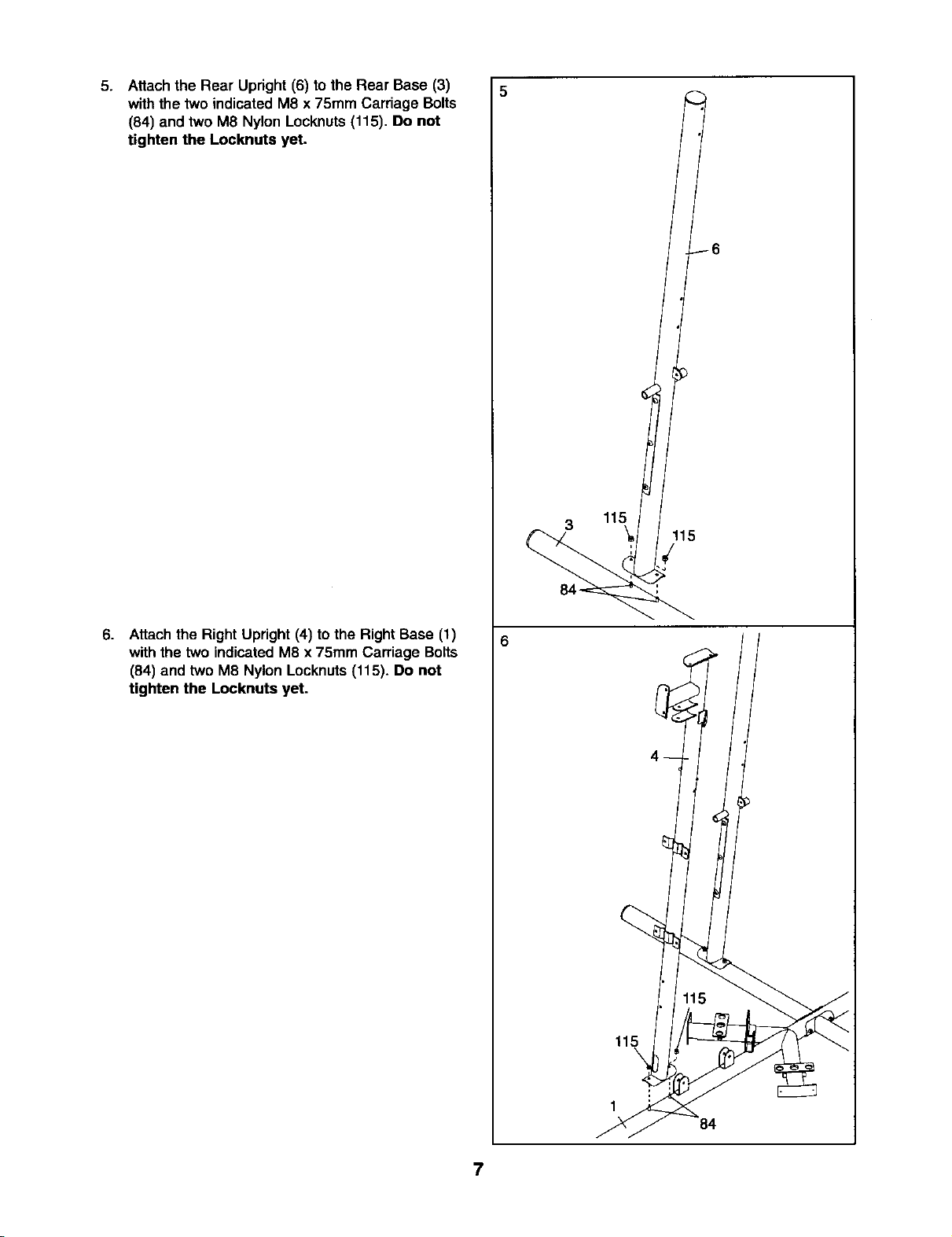
5.
Attach the Rear Upright (6) to the Rear Base (3)
withthe two indicatedM8 x 75mm Carriage Bolts
(84) and two M8 Nylon Locknuts (115). Do not
tighten the Locknuts yet.
6
6.
Attachthe Right Upright (4) to the Right Base (1)
withthe two indicatedM8 x 75mm Carriage Bolts
(84) and two M8 Nylon Locknuts(115). Do not
tighten the Locknuts yet.
3 115
115
/
6
115
\
1
84
7
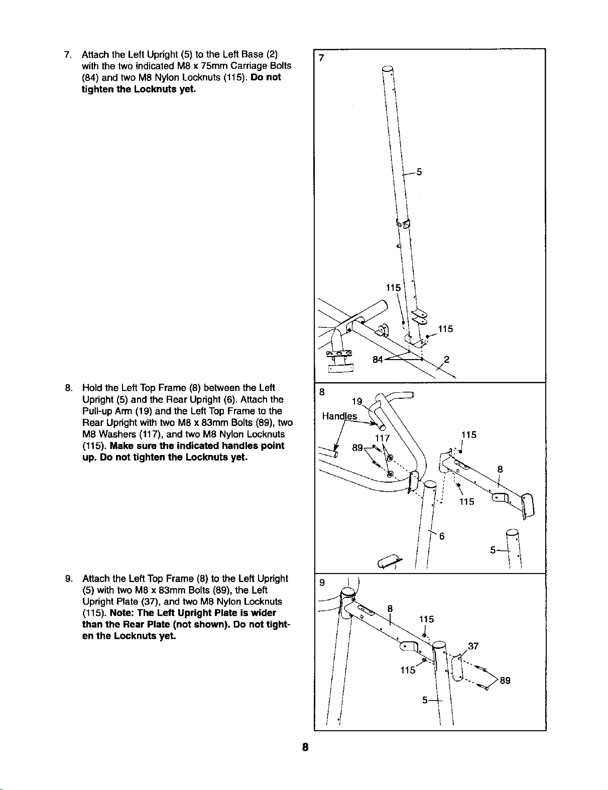
7,
Attach the Left Upright (5) to the Left Base (2)
with the two indicated M8 x 75mm Carriage Bolts
(84) and two M8 Nylon Locknuts (115). Do not
tighten the Locknuts yet.
5
115
8,
Hold the Left Top Frame (8) between the Left
Upright (5) and the Rear Upright(6). Attach the
Pull-up Arm (19) and the Left Top Frame to the
Rear Upright with two M8 x 83mm Bolts (89), two
M8 Washers (117), and two M8 Nylon Locknuts
(115). Make sure the indicated handles point
up. Do not tighten the Locknuts yet.
9.
Attachthe Left Top Frame (8) to the Left Upright
(5) with two M8 x 83mm Bolts (89), the Left
Upright Plate (37), and two M8 Nylon Locknuts
(115). Note: The Left Upright Plate is wider
than the Rear Plate (not shown). Do not tight-
en the Locknuts yet.
2
8
19
Handles
115
8
i'\
115
8
115
37
8
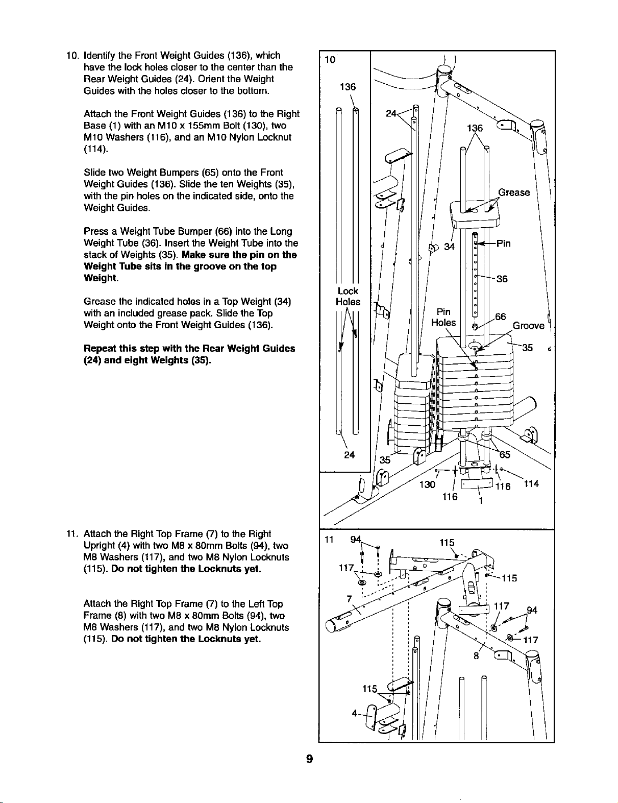
10. Identifythe Front Weight Guides (136), which
have the lockholes closerto the center thanthe
Rear Weight Guides (24). Orient the Weight
Guides with the holes closerto the bottom.
Attachthe Front Weight Guides (136) to the Right
Base (1) with an M10 x 155mm Bolt (130), two
M10 Washers (116), and an M10 Nylon Locknut
(114).
Slide two Weight Bumpers (65) ontothe Front
Weight Guides (136). Slide the ten Weights (35),
withthe pin holeson the indicatedside, onto the
Weight Guides.
Press a Weight Tube Bumper (66) intothe Long
Weight Tube (36). Insert the Weight Tube intothe
stack of Weights (35). Make sure the pin on the
Weight Tube sits in the groove on the top
Weight.
Grease the indicatedholes in a TopWeight (34)
withan included grease pack. Slide the Top
Weight onto the Front Weight Guides (136).
Repeat this step with the Rear Weight Guides
(24) and eight Weights (35).
10
136
Lock
Holes
\
11. Attach the RightTop Frame (7) to the Right
Upright (4) with two M8 x 80mm Bolts (94), two
M8 Washers (117), and two M8 Nylon Locknuts
(115). Do not tighten the Locknuts yet.
Attach the Right Top Frame (7) tothe Left Top
Frame (8) with two M8 x 60mm Bolts(94), two
M8 Washers (117), and two M8 Nylon Locknuts
(115). Do not tighten the Locknuts yet.
11
L
24
130
116
115
7
115
114
9
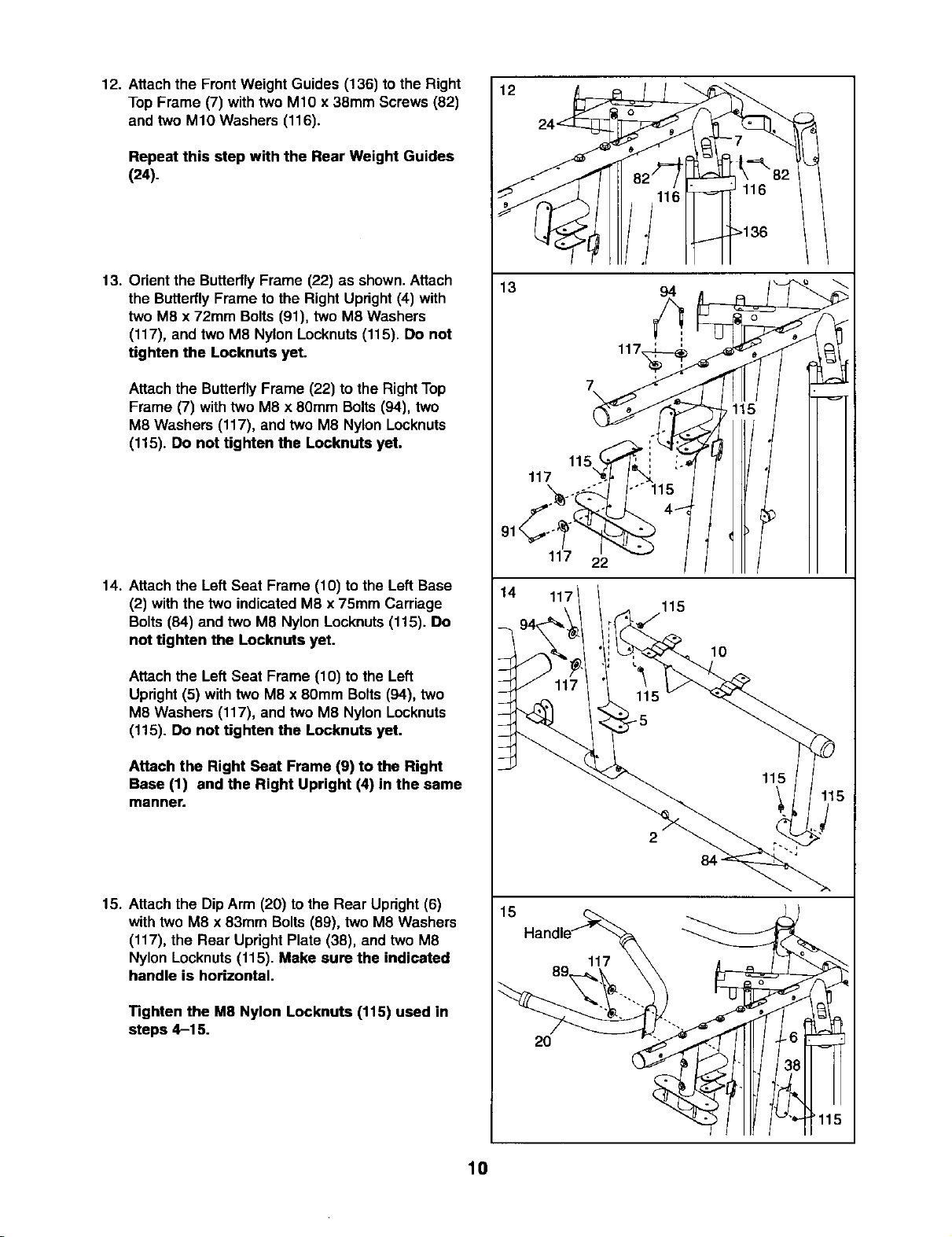
12. Attach the Front Weight Guides (136) to the Right
Top Frame (7) with two M10 x 38mm Screws (82)
and two M10 Washers (116).
Repeat this step with the Rear Weight Guides
(24).
12 24"_
13. Orientthe ButterflyFrame (22) as shown.Attach
the ButterflyFrame to the Right Upright (4) with
two M8 x 72ram Bolts (91), two M8 Washers
(117), and two M8 Nylon Locknuts (115). Do not
tighten the Locknuts yet.
Attach the Butterfly Frame (22) to the Right Top
Frame (7) with two M8 x 8Omm Bolts(94), two
M8 Washers (117), and two M8 Nylon Locknuts
(115). Do not tighten the Locknuts yet.
14. Attach the Left Seat Frame (10) to the Left Base
(2) with the two indicated M8 x 75mm Carriage
Bolts (84) and two M8 Nylon Locknuts (115). Do
not tighten the Locknuts yet.
Attach the Left Seat Frame (10) to the Left
Upright(5) with two M8 x 8OmmBolts(94), two
M8 Washers (117), and two M8 Nylon Locknuts
(115). Do not tighten the Locknuts yet.
13
117
117 22
14 117
115
94
7
\
115
10
Attach the Right Seat Frame (9) to the Right
Base (1) and the Right Upright (4) in the same
manner.
15. Attach the Dip Arm (20) to the Rear Upright (6)
with two M8 x 83mm Bolts(89), two M8 Washers
(117), the Rear Upright Plate (38), and two M8
Nylon Locknuts (115). Make sure the indicated
handle is horizontal.
Tighten the M8 Nylon Locknuts (115) used in
steps 4-15.
115
2
84
15
2O
10
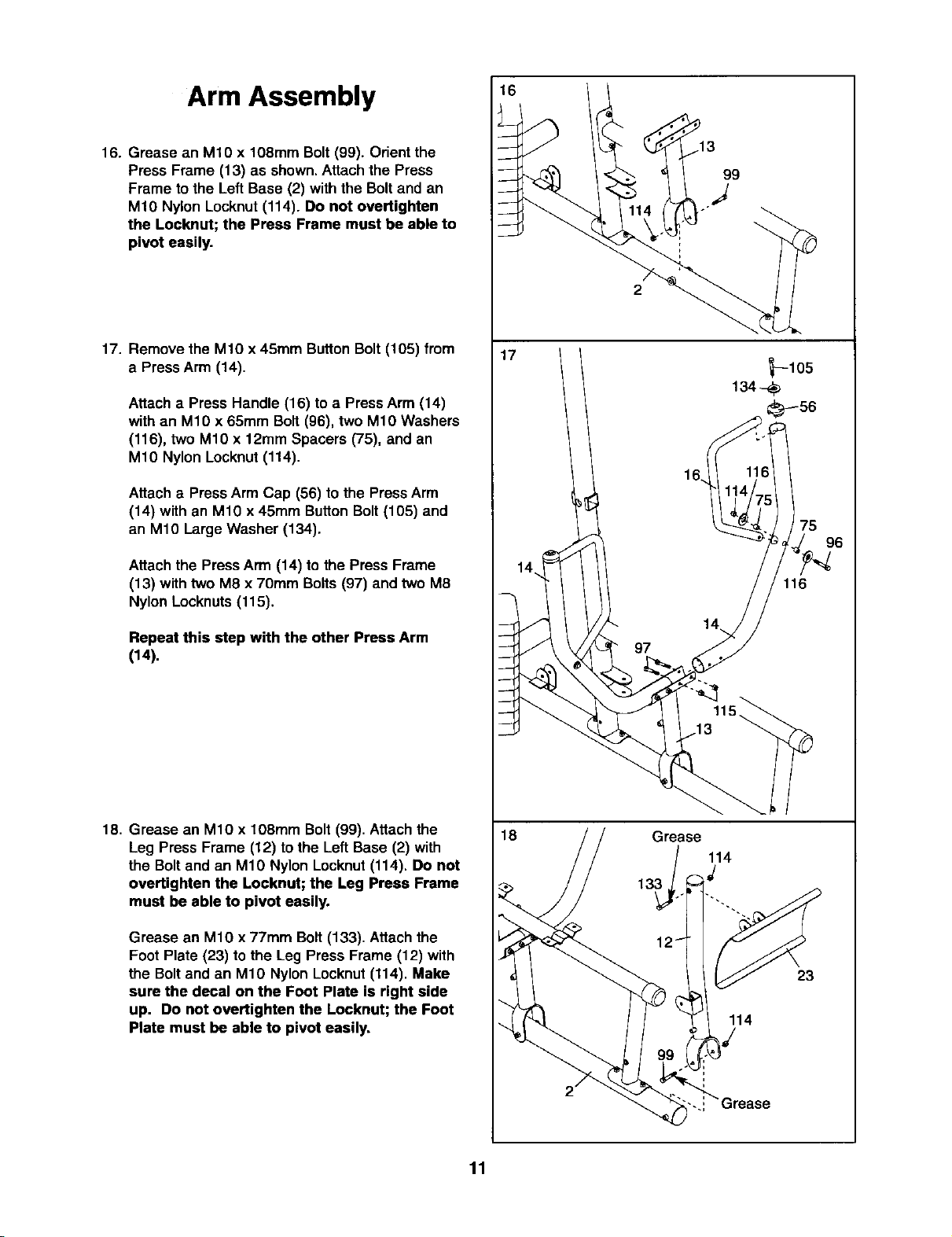
Arm Assembly t6
16. Grease an M10 x 108mm Bolt (99). Orient the
Press Frame (13) as shown.Attach the Press
Frame to the Left Base (2) with the Bolt and an
M10 Nylon Locknut(114). Do not overtighten
the Loeknut; the Press Frame must be able to
pivot easily.
99
J
2
17. Remove the M10 x 45mm Button Bolt (105) from
a Press Arm (14).
Attach a Press Handle (16) toa PressArm (14)
with an M10 x 65mm Bolt (96), two M10 Washers
(116), two M10 x 12mm Spacers (75), and an
M10 Nylon Locknut(114).
Attach a Press Arm Cap (56) to the PressArm
(14) with an M10 x 45mm ButtonBolt(105) and
an M10 Large Washer (134).
Attach the Press Arm (14) to the Press Frame
(13) with two M8 x 70ram Bolts (97) and two M8
Nylon Locknuts(115).
Repeat this step with the other Press Arm
(14).
17
116
97
18. Grease an M10 x 108ram Bolt(99). Attachthe
Leg Press Frame (12) to the Left Base (2) with
the Boltand an M10 Nylon Locknut(114). Do not
overtighten the Locknut; the Leg Press Frame
must be able to pivot easily.
Grease an M10 x 77ram Bolt (133). Attachthe
Foot Plate (23) to the Leg Press Frame (12) with
the Boltand an M10 Nylon Locknut(114). Make
sure the decal on the Foot Plate is right side
up. Do not overtighten the Locknut; the Foot
Plate must be able to pivot easily,
11
18
Grease
13 _/
3_o 114
23
114
9 "/

19. Attach the Leg Bumper(76) tothe Right Seat
Frame (9) withan M4 x 16mm Self-tapping Screw
(113) and an M4 Washer (131).
Grease an M10 x 75mm Bolt (104). Attach the
Leg Lever (11) to the Right Seat Frame (9) with
the Boltand an M10 Nylon Locknut(114). Make
sure the "U"-rod is on the indicated side of
the Leg Lever. Do not over tighten the
Locknut; the Leg Lever must be able to pivot
easily.
19
114
11
20. Hold the Dip Assist(21) aroundthe Rear Upright
(6) and Left Upright (5) as shown. Make sure the
Dip Assist is under the indicated rod.
Attach the Cross Brace (64) to the Dip Assist (21)
with an M10 x 232mm Bolt(108), two M10
Washers (116), and an M10 Nylon Locknut (114).
Grease an M10 x 232mm bolt(108). Attachthe
DipAssist (21) to the Left Upright (5) with the Bolt
and an M10 Nylon Locknut(114). Do not over-
tighten the Locknut; the Dip Assist must be
able to pivot easily.
Attach the DipAssist Latch(67) to the DipAssist
(21) with an M10 x 85mm Bolt (107), two M10
Washers (116), a 12mm Spacer (75), and an Mt0
Nylon Locknut(114). Do not overtighten the
Locknut; the Dip Assist Latch must be able to
pivot easily. Engage the Latch overthe rod on
the Rear Upright (6).
21. Wet the lowerend of the LeftButterflyArm (18)
withsoapy water.Slide a Large Foam Pad (79)
ontothe ButterflyArm,
20
21
Note: an entire grease packet should be used
for this step. Grease an M10 x 89ram Bolt (92)
and the indicated edges oftwo Arm Bushings
(59). Attach the Left ButterflyArm (18) to the
ButterflyFrame (22) with the Bolt,an M10 Large
Washer (134), the two Arm Bushings,and an
M10 Nylon Locknut (114). Make sure the bolt
head fits inside the hole in the Butterfly
Frame.
Repeat this step with the Right Butterfly Arm
(17).
l
59r_ase__ 79-_
12
 Loading...