

Weider 831150360 Owner’s Manual
PATENTPENDING
WELDER
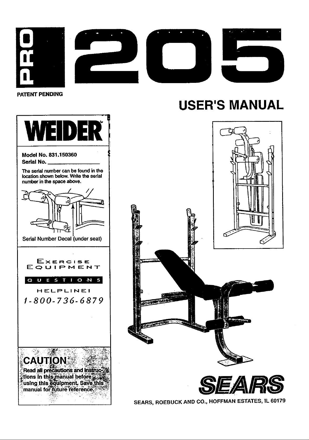
Model No. 831.150360
Serial No.
The sedal number can be found in the
location shown below. Wdte the serial
number in the space above.
Serial Number Decal (under seat)
USER'S MANUAL
HELPLINE!
/-800-736-6879
SFARS
SEARS, ROEBUCK AND CO., HOFFMAN ESTATES, IL 60179
TABLE OF CONTENTS
IMPORTANT PRECAUTIONS ............................................................. 2
BEFORE YOU BEGIN .................................................................. .3
PART IDENTIFICATION CHART .......................................................... .4
ASSEMBLY ........................................................................... 5
ADJUSTING.THE WELDER PRO 205 ........................................................ 9
EXERCISE GUIDELINES ................................................................ 11
PART MST ........................................................................... 14
EXPLODED DRAWING ................................................................. 15
ORDERING REPLACEMENT PARTS ................................................ Back Cover
FULL 90 DAY WARRANTY ....................................................... Back Cover
IMPORTANT PRECAUTIONS
WAHPlINU: io,reauce me riSKOXser pus Iniury; reap the lrollowln_ imDodant precautions befoi_._:_
using the weight bench.
1.,* Re_d all il'tstructions In this manuaJ_before._t_u.._Keep hands and feet away from movini] ,_arts_
' " using the,_welght bench.
"Always wear athleUc shoes for foot protec-
2. Use the weight bench only as de_ribecl]n "tion while'exercising.
this manual.
-10. The weight bench does not include weights. ,
3. Use the weight bench only on a level,surf.ace._,_'_,, The weight bench is designed to support a, ":
Cover the floor beneath, the weigh t_,benchJora_:_: maximum of 510 pounds, Including the User,L_
protection• . a weight bar and weights. Do not place more
':_=thano310 pounds, inc uding a weight bar and ,i
4.. Inspect and bghten all parts each _ we|ghLs, on the we|eht rests. Do not olai:e -_,_
use,the we,ght bench. Replace an_ _-:--'more than 150 pounds on the leg lever_
part_ immediately. :._'_,_",_, _- .- -" , . ..... ,_,.'-_',_'_
,",_:: _,+j_ l_.-When using the backrest'make sure that,the,
5. Keep small chddren ah'_ pets away,:_romi_J)_'_,_,,-adJustment tube is firmly seated in the '_',\=-_:,_
weight bench at all t.mes. ;,,adjustment brackets on the uprights. " , =_-
weight on each-side of_your barbel! (not_,_.," Lexercising; stop immediatslv and bealn cool _€
61 Always be.,su=re_,themjs-;_znequa!_.ap!ount_)f_._12.'lf you feal pain or dizziness at any time whlle ,___• . •.._, . ..., .._\ _ .... - _, _
included) when you a_using IL ,:_:- ",- :=".._,_,,_. :ing down. ' . , - -
,, _._
7.- When you are using the weight carrlage_ be, , 13.-:1t is the responsibility of the owner to ensure :',
sure there is an equal amount of weight on that all users of the weight bench are ade- :_¢',
each side of the weight tube. . . quately Informed of all precautions.. _:_?, =;.
WARNING. Bfffore beginning this or any exercise program;'consult your physician: This is es_l_;lly_
impo ,r,tantfor persons overthe age of _ or persons with pre-existing hdalth pro'b!ems. Redid all'_._:
instruct!ons_fore usIng.,S .EARS assumes no*responsibility for personal injury or.property damaue_
sustained byor through the'use of this product•
2
BEFORE YOU BEGIN
Thank you for selecting the WELDER= PRO 205
Weight Bench. The versatile PRO 205 Weight Bench
is designed to be used with your own weight set (not
• included) to develop every major muscle group of the
body. Whether your goal is a shapely figure, dramatic
muscle size and strength, or a healthier cardiovascular
system, the PRO 205 Weight Bench will help you to
achieve the specific results you want.
For your benefit, read this manual carefully before
using the WELDERe PRO 205 Weight Bench. If you
have additional questions, please call our toll-free
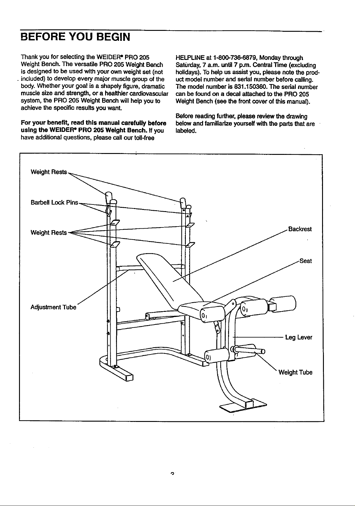
Barbell Lock
HELPLINE at 1-800-736-6879, Monday through
Saturday, 7 a.m. until7 p.m. Central "13me(excluding
holidays). To help us assist you, please note the prod-
uct model number and sedal number before calling.
The model number is 831.150360. The serial number
can be found on a decal attached to the PRO 205
Weight Bench (see the front cover of this manual).
Before reading further, please review the drawing
below and familiarize yourself with the pads that are
labeled.
Adjustment Tube
Leg Lever
Weight Tube
PART IDENTIFICATION CHART
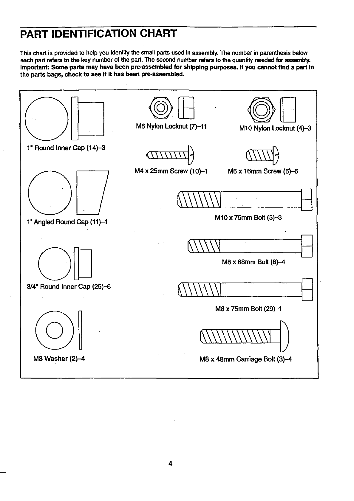
This chart is provided to help you identify the small parts used in assembly. The number in parenthesis below
each part refers to the key number of the part. The second number refers to the quantity needed for assembly.
Important: Some ports may have been pre-assembled for shipping purposes. If you cannot find a part in
the parts bags, check to see if It has been pre-aseembled.
1" Round Inner Cap (14)-3
1' Angled Round Cap (11)-1
3/4" Round Inner Cap (25)-6
M8 Nylon Locknut (7)-11
M4 x 25mm Screw (10)-1 M6 x 16mm Screw (6)-6
M10 x 75mm Bolt (5)--3
M10 Nylon Locknut (4)-3
M8 x 68mm Bolt (8)-4
M8 Washer (2)-4
M8 x 75mm Bolt (29)-1
M8 x 48mm Carriage Bolt (3)-4
4
ASSEMBLY
Before beginning assembly, carefully rrad the
following Information and InstrucUons:
• Place all parts of the WELDER= PRO 205 in a
cleared area and remove the packing materials;
do not dispose of the packing materials until
assembly is completed.
• Read each assembly step before you begin.
• For help identifyingthe small parts used in
assembly, use the PART IDENTIRCATION
CHART on the previous page. Note: Some
small parts may have been pre-attached forship-
ping purposes. If d pad is not in the pads bag,
check to see if it has been pre-attached.
• _ghten all pads as you assemble them, unless
instructed to do otherwise.
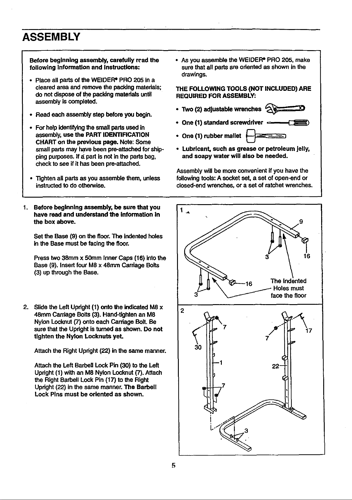
1. Before beginning assembly, be sure that you
have read and understand the Information In
the box above.
• As you assemble the WEIDEFP PRO 205, make
sure that all pads are odented as shown in the
drawings.
THE FOLLOWING TOOLS (NOT INCLUDED) ARE
REQUIRED FOR ASSEMBLY:
• Two (2) adjustable wrenches
• One (1) standard screwdriver
• One (1) rubber mallet
• Lubricant, such as grease or petroleum jelly,
and soapy water will also be needed.
Assembly will be more convenient if you have the
following tools: A socket set, a set of open-end or
closed-end wrenches, or a set of ratchet wrenches.
Set the Base (9) on the floor. The indented holes
in the Base must be facing the floor.
Press two 38ram x 50mm Inner Caps (16) into the
Base (9), Insert four M8 x 48ram Carriage Bolts
(3) up through the Base.
.
Slide the Left Upright (1) onto the indicated M8 x
48ram Carriage Bolts (3). Hand-tighten an M8
Nylon Locknut (7) onto each Carriage Bolt. Be
sure that the Upright is tumed as shown. Do not
tighten the Nylon Locknuta yet.
Attach the Right Upright (22) in the same manner.
Attach the Left Barbell Lock Pin (30) to the Left
Upright (1) with an M8 Nylon Locknut (7). Attach
the Right Barbell Lock Pin (17) to the Right
Upright (22) in the same manner. The Barbell
Lock Pins must be oriented as shown.
\ -F Holes must
3 _ face the floor
2
7
3O
J 1
-- 22 __
L j7
16
17
L
5
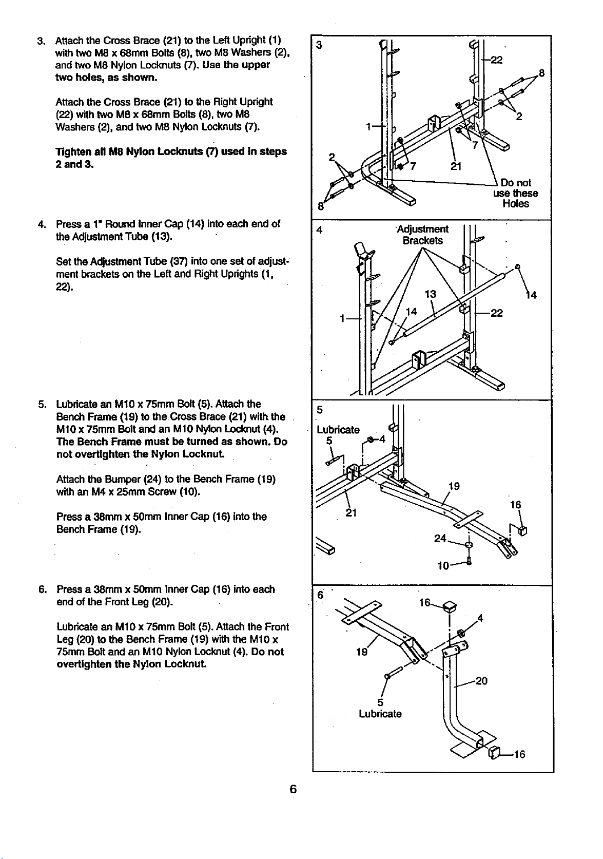
3. Attachthe Cross Brace (21) to the Left Upright (1)
with two M8 x 68mm Bolts (8), two M8 Washers (2),
and two M8 Nylon Locknuts (7). Use the upper
two holes, as shown.
Attach the Cross Brace (21) to the Right Upright
(22) with two M8 x 68mm Bolts (8), two M8
Washers (2), and two M8 Nylon Locknuts (7).
Tighten all M8 Nylon Locknuts (7) used in steps
2 and 3.
.
Pressa 1"RoundInnerCap (14) intoeach endof
theAdjustmentTube(13).
Set the Adjustment Tube (37) into one set of adjust-
ment brackets on the Left and Right Uprights (1,
22).
Do not
use these
Holes
4 Adjustment
Brackets
o
Lubricatean M10 x 75mm Bolt (5). Attach the
Bench Frame (19) to theCross Brace (21) withthe
M10 x 75mm Bolt and an Mt0 Nylon Locknut(4).
The Bench Frame must be tumed as shown. Do
not overtlghten the Nylon Locknut.
Attach the Bumper (24) to the Bench Frame (19)
with an M4 x 25ram Screw (10).
Press a 38mm x 50mm Inner Cap (16) intothe
Bench Frame (19).
.
Press a 38mm x 50ram Inner Cap (16) into each
end of the Front Leg (20).
Lubricate an M10 x 75mm Bolt (5). Attach the Front
Leg (20) to the Bench Frame (19) withthe M10 x
75mm Bolt and an M10 Nylon Locknut (4). Do not
overUghten the Nylon Locknut.
Lubricate
19
16
21
5
Lubricate
6
 Loading...