

Page 1
INSTRUCTION MANUAL
MODEL 801
50
MHz PULSE
THIS DOCUMENT CONTAINS INFORMATION PROPRIETARY TO WAVETEK. THE INFORMATION IN
THIS DOCUMENT IS NOTTOBE USED FOR DUPLICATED
IN ANY MANNER WITHOUT THE PRIOR APPROVAL
IN WRITING OF WAVETEK.
SAN DIEGO
9045Balboa Ave.,
P. 0.Box 651, SanDiego, California 92112
Tel 7
14/279-2200
San Diego,
Calif.
92123
TWX 9 1 o-335-2007
REV C .
8/77
Page 2
SECTION
1
GENERAL DESCRIPTION
1.1 THE MODEL 801
The Model 801 is a 50 MHz general purpose laboratory pulse
generator. The instrument gives you full control in primary
pulse triggering and shaping plus simultaneous TTL, ECL,
ECL
and sync pulses. The primary pulse output has controllability in offset and independent rise/fall durations, as well
as pulse width, pulse delay and a choice of positive, negative
or complementary outputs. The TTL, ECL and
fixed levels and rise times that are standard for use with
compatible devices. The primary pulse has minimum rise
and fall times of 7 ns and a maximum of 250 ms.
+20
The output is
provides
levels are fully adjustable through
External triggering can be set to any point of the rising or
trailing edge of the trigger signal. Single pulses or pulse pairs
may be triggered; pulse width may be trigger controlled;
continuous pulses may be gated and a precise number of
pulses may be triggered for a ‘burst’ output. Manual and
external triggering is indicated by an LED on the front panel
for rapid visual set of trigger level.
1.2 SPECIFICATIONS
1.2.1
Five Simultaneous Pulse Outputs
Fixed level ECL,
with variable amplitude
available over a 5 Hz to
to 20 ns periods).
+lO
Versatility
volts with
volts into a
m,
5Oa
source impedance which
5Oa
load. Upper and lower pulse
+20
volts.
TTL and sync pulses and a pulse
and variable rise/fall times. Pulses
50 MHz frequency range (200 ms
ECL
are of
double pulse controlled by delay control. Double pulse at
all outputs except sync.
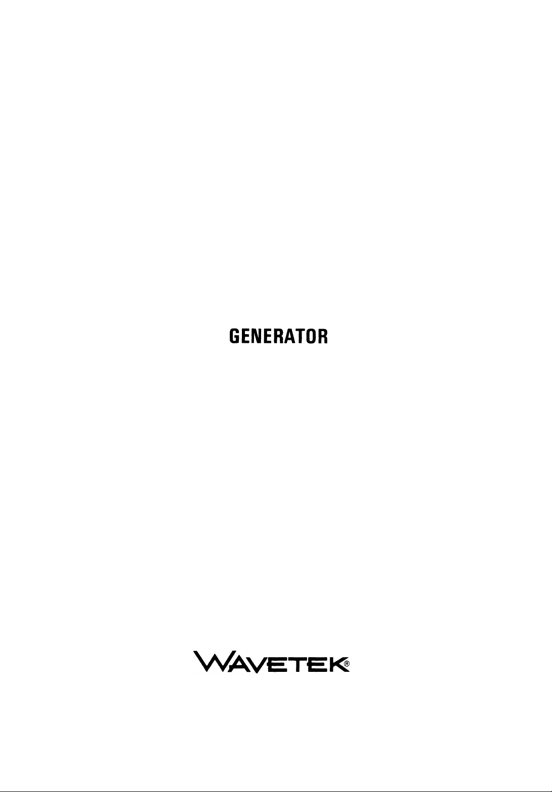
External Width: External signal at trigger input and trigger
level control determine output pulse width and period as
shown.
TRIGGER LEVEL WINDOW
TRIGGER LE
Trigger Burst:
time) for pulse burst (1 to 100 pulse range) as shown.
External trigger starts internal gate (delay
TRIGGER LEVEL
TRIGGER
+
I
‘DELAY TIME’ GATE
PULSE
1.2.2
Pulse Outputs
BURST OUTPUT
-I
hlnn
I
Operational Modes
Continuous: Generator
frequency.
Triggered: Generator quiescent until triggered by external
signal or front control, then generates one pulse.
Gated: As triggered mode, except generator oscillates for
the duration of the external signal.
Double
except
Pulse: Continuous, trigger and gate, as above,
two pulses for
oscillates continuously at selected
each period. Space between pulses of
Variable Amplitude Pulse
Upper and lower pulse levels are independently adjustable.
*2OV
Pulse dynamic range
5052 source. The pulse is 20V p-p maximum, 1V p-p mini-
mum. Into a
maximum pulse 1OV p-p, minimum pulse
Overshoot and ringing is less than
+100
mV) into 5Oa load.
Preshoot is less than
5Oa load.
into
is
5Os1
termination, dynamic range is
into an open circuit from the
0.5V
*(5%
of amplitude setting
+(5%
of amplitude setting
p-p.
+100
+lOV,
mV)
l-l
Page 3
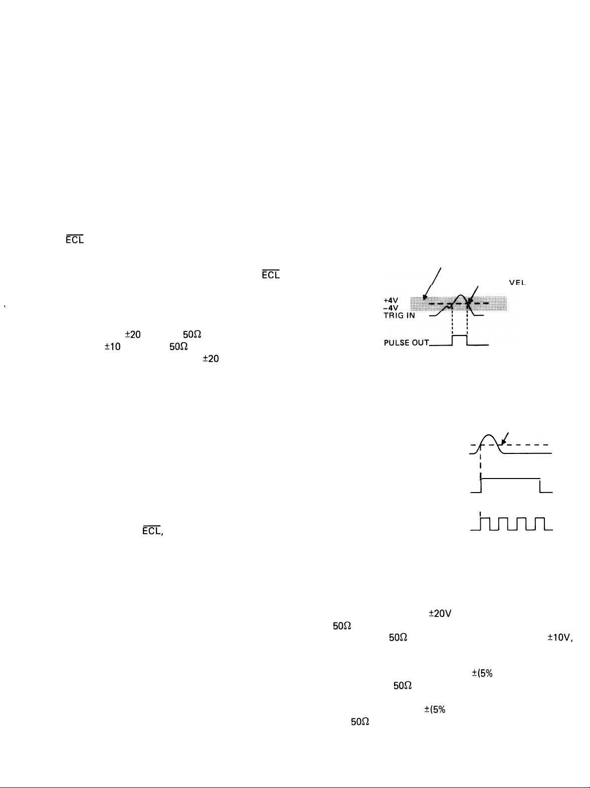
Fixed (ECL, ECL, TTL) Pulses
Pulse levels for
ECL
Em
ECL, ECL Transition Time: < 6 ns.
TTL
TTL Transition Time: < 10 ns.
5On
loading as shown:
-1 8” A
.
-,
.8V
--7-r--
<o
4Vn
.
Sync Pulse
Sync pulse is 0 to at least
+1V
from a
-0.9V
-“”
>2s4V
5Oa
source.
Delay
Pulse occurrence can be delayed from less than 10 ns to
100 ms with respect to the sync pulse. Maximum duty
cycle is 70% for periods to 200 ns, decreasing to 30% for
20 ns periods.
Delay jitter is less than 0.1% plus 50 picoseconds.
Fixed delay is as shown:
TRIGGER LEVEL
TRIGGER INPUT
FIXED
DELAY4 b -4Ons
Normal/Complement Control
Normal pulse or its complement is selected. The normally
quiescent and active levels are reversed in complement
format. This control affects all outputs except sync pulse.
1.2.3
Period range is from less than 20 ns to greater than 200 ms
in 7 overlapping ranges.
Period jitter is less than 0.1% plus 50 picoseconds.
Time Domain
Width
Width range is from less than 10 ns to 100 ms in 7 overlapping ranges. Maximum duty cycle is 70% for periods to
200 ns, decreasing to 50% for 20 ns periods. Range switch
also has a square wave detent
‘L
duty cycle is 50 -+4% to 2
50 +15% at 20 ns period.
Width jitter is less than 0.1% plus 50 picoseconds.
( % ).
pus
period changing to
1.2.4
SYNC PULSE
FIXED DELAY
VARIABLE
AMPLITUDE
PULSE
Input Characteristics
t
1
--+( k ~20
__n-
ns
External Trigger
The external signal required to trigger the generator has a
minimum amplitude of
to
k600 mV
mum amplitude of
Input impedance is approximately 1 ka
22 pF
Triggering is selected to occur at either rising or falling edge
of trigger signal; triggering level is adjustable to be between
+4V.
external and manual trigger occurrence accepted.
1.2.5
p-p to 50 MHz (from
An LED lights for approximately 100 ms for each
General
+200 mV
+lOV
with a minimum width of 10 ns.
p-p to 5 MHz increasing
5Oa
source) and a maxi-
in parallel with
Sync pulse duty cycle is 50
period, changing to 50 +I 5% at 20 ns period except in
trigger and external width modes, in which case it is determined by the trigger signal.
24% of pulse period to 2
Transition Time
For variable amplitude pulse only. Independently adjustable
leading and trailing edges from less than 7 ns (5 ns typical)
to 250 ms in 7 overlapping decade ranges (measured from
10 to 90% points). Verniers give
ranges except 5 ns, which gives 25: 1.
Linearity:
10 to 90% points on pulse.
l-2
For transition greater than 10 ns
50:1
adjustment on all
+5% between
pus
Environmental
Specifications apply at 25°C
Instrument will operate from 0°C to 50°C.
*5”C
after 1 hour warm-up.
Dimensions
28.8
cm (11.4 in.) wide; 17.3 cm (6.8 in.) high; 29 cm
(11.4
in.) deep.
Weight
5.4
kg (12 lb) net; 7.3 kg (16 lb) shipping.
Power
90
to1 10V,108 to
50to400 Hz;
132V,
60 watts nominal.
to220Vor216
180
to250V;
Page 4

OPERATION
3.1
CONTROLS
The generator controls and connections are shown in
figure 3-1 and keyed to the following descriptions.
1
MODE Switch
0
modes.
CONT - Continuous pulses at all output connectors.
TRIG
ger appears (see
pulses occur,depending on mode and control settings.
GATE
trigger edge appears (see
occur until the trigger signal transverses the generator
trigger level again.
AND CONNECTORS
Selects one of the following eight
-
DC level at all outputs until a suitable trig-
-
@
, @
);
then one or more
DC level at all outputs until a suitable
-
@
, @
);
then pulses
EXT WIDTH
suitable trigger appears (see
pulse occurs which has the duration of the trigger
signal.
TRIG BURST
suitable trigger appears (see
gate time
as determined by
CONT DBL - As for CONT except two pulses occur
for each pulse period. Time to second pulse is set by
5
0
TRIG DBL - As for TRIG except two pulses occur
in the one pulse period. Time to second pulse is set”
by @
@
.
DC level at all outputs until a
-
@
, @
);
then a
DC level at all outputs until a
-
@
, @
)
to trigger a
;
then a fixed number of pulses occur
@
and
@
.
Figure 3-l . Controls and Connections
3-I
Page 5

50% DUTY TIME
WHEN TRIGGERING
--
IS INTERNAL
--
SYNC PULSE
NORMAL
AT
5Oi2
COMPLEMENT
PULSE AT
PULSE
OUT
50i2OUT
-
DELAY
LEADING EDGE
TRANSITION TIME
I
I
UPPER
-
--1
-LEVEL
TRAILING EDGE
TRANSITION TIME
LOWER
LEVEL
N
LOWER
-LEVEL
J
UPPER LEVE&
--
NORMAL
DOUBLE PULSE
AT
5Oi2
OUT
NO
TE:
Underline indicates a front panel con trolled parameter.
I
I
b
WIDTH
B
F
Figure 3-2. Pulse Parameters
3-2
WIDTH
e
Page 6

GATE DBL - As for GATE except two pulses occur
for each pulse period. Time to second pulse is set by
5
.
0
0
2
TRIGGER Switch- Selects one of three trigger
methods: manual, an external trigger signal’s rising
edge or an external trigger signal’s falling edge. The
external trigger signal is applied at
Q9
ECL Connector-An output
9
0
logic level pulse whose occurence and duration are
controllable. Levels are
active.
OUTPUT Switch- Selects a normal pulse or its
30
0
complement which swaps the active and quiescent
levels. Affects all outputs, except SYNC,
with an
-1.8V
emitter-coupled-
quiescent,
-0.9V
___ 0 4
--
0
5
0
0
LEVEL Control- Inner knob sets acceptance thresh-
old for trigger signal at
MAN TRIG Switch
3
tion that equals the time the switch is held down.
Output depends on the mode selected (see
TRIG Indicator
mately 100 ms for each trigger signal accepted.
PERIOD/RATE Switch- Selects one of seven ranges
of pulse period. Calibrated in seconds and hertz.
VARIABLE Control - Varies the pulse period within
the range selected by the outer knob. Clockwise increases the pulse period and decreases frequency.
DELAY Switch
pulse delay, time to second pulse of double pulses
or length of burst, depending on mode setting. OFF
position ensures minimum delay.
VARIABLE Control
the range selected by the outer knob. Clockwise increases the delay.
WIDTH
6
width or an approximate 50% duty cycle.
VARIABLE Control
the range selected by the outer knob except
Switch -
-
-
An LED which lights approxi-
-
Selects one of seven ranges of
Selects one of seven ranges of pulse
@
.
Supplies a trigger with a dura-
-
Varies the delay time within
-
Varies the pulse width within
@
ins.
11
ECL Connector- An output like the ECL out-
0
put
reversed.
32
TTL Connector
).
0
sistor-logic level pulse whose occurence and duration
are controllable. Level is <
active into a 5Ost termination.
13
TRAILING EDGE Control - Varies the duration of
0
the
5Oa
set by 1
time. Full cw exceed upper value of the selected
range. Trailing edge time is not part of WIDTH time.
4 SYNC
0
to
> 0.5V
when the generator is in a continuous mode (see
1 ). In other modes, width is determined by the
0
time between initial transition of the trigger signal
through the trigger level to the trailing transition.
15
LEADING EDGE Control - Same as013 but
0
varies the duration of the leading edge of the
OUT pulse. Leading edge time is part of WIDTH time.
TRIG INPUT Connector - Accepts an external
16
0
signal to trigger the generator. Triggers on rising or
falling edge of input as determined by
paragraph 1.2.3 for input specifications.
except active and quiescent levels are
@
-
An output with a transistor-tran-
0.4V
quiescent, >
OUT pulse trailing edge. Duration range is
Clockwise rotation increases edge
.
0
Connector- An output with a pulse of OV
into
5Oa
termination and a square wave
@
2.4V
SOS2
. See
LOWER LEVEL Control - Outer knob sets the
0
7
--
lower level of the
varied from-20 to
or -10 to
mum pulse height is 20 volts open circuit.
UPPER LEVEL Control
level of the
identical to that stated for the lower level.
5OQ
0
8
erator. Pulses from this output may be controlled in
level and transition time as well as frequency and
width.
OUT
+10
Connector
5Os2
OUT pulse, which may be
+20
volts into an open circuit
volts into a 5052 termination. Maxi-
-
Inner knob sets the upper
5052 OUT pulse. Upper level range is
-
The main output of the gen-
TRANSITION TIME Switch - Selects one of seven
17
0
ranges for
Actual durations within a range are set by
and
POWER Switch -Pulse generator on/off switch.
‘I8
0
NOTES ON OPERATION
3.2
Operational modes are described in paragraph 3.1 under the
mode switch. The pulse itself may be shaped in width,
leading and trailing edge transition times, upper level, lower
level, frequency of occurrence (period) and delay with
5Oa
OUT pulse rise and fall durations.
@
@
.
3-3
Page 7

respect to its sync pulse. These pulse parameters are shown
in figure 3-2. Specific setups for each mode are given in
paragraph 3.3.
3.2.1
White Marks
3.2.4
Only
to the circuit under test. A
Output Terminations
5OQ RG58U
cable should be used to connect the 801
5OQ
2W load should be used at
the circuit end of the cable for maximum pulse fidelity.
When first becoming familiar with the 801, the white mark
settings are handy. The white mark settings for the front
panel switches will always give a 5k to 50
kHz
sync signal
when power is on. The same settings will give 50% duty
time, TTL, ECL, ECL and
5Os2
OUT pulses; the LOWER
LEVEL/UPPER LEVEL control may need adjusting to observe the
501sz
OUT on an oscilloscope. Once the output is
observed, each control can be adjusted and observed until
the desired result is obtained.
3.2.2
Pulse Width, Transition and Delay
Narrow duty cycle pulses require the NORMAL OUTPUT
while greater than 70% duty cycle pulses require the COMP
OUTPUT setting. Pulse width plus trailing edge time plus
delay time settings should not exceed the period time. (See
figure 3-2.) The sum of width, trailing edge and delay actually must be somewhat less than period time by an amount
that depends upon the period time selected. Therefore,
when the sum of the desired width, trailing edge and delay
time exceeds 70% of the period time, the pulse should be
observed to make sure it is as desired.
The 50% duty time width setting
( ‘L )
is meant to be used
in continuous mode. Other modes result in the following
default conditions.
The
5Oa terminations should always be used on the SYNC
and TTL outputs and
5OQ
Thevenin loads should be used
on the ECL outputs.
3.2.5
Nonlinear and Reactive Loads
Both nonlinear and reactive loads will cause pulse distortion.
Reactive loads driven with fast transitions cause voltage
spikes that can damage the 801 output amplifier. If it is
necessary to drive reactive loads directly, the instrument
must be protected against these voltage spikes.
3.2.6
Duty Cycle
Always use the lowest range possible for both delay and
width functions. This will reduce the recovery time of the
one-shots and extend the maximum duty cycle of the 801
to its fullest capability.
3.2.7
Output Mixing
The outputs of two 801’s may be mixed using the following
network.
)
MIXED OUTPUT
Mode Selected
TRIG
I-I
DBLX
CONT
TRIG
DBL\
GATE
DBL’L
3.2.3
ECL
Figure 3-3 shows a
output
A triggered 10 ns pulse
A continuous output of paired 10 ns pulses
A triggered output of paired 10 ns pulses
A gated output of paired 10 ns pulses
Termination
5.2/0volt 5052
ECL termination. Similar
5Oa terminations can be made for ECL circuits with other
voltage arrangements.
801
ECL
3 FT RG58U COAX
-
-5.2V
ECL CIRCUIT
j
OR EQUIVALENT
Figure 3-3. ECL Termination
3-4
20.5a 20.5a
FROM
FIRST 801
OUTPUT
FROM
SECOND 801
OUTPUT
Maximum output from either generator is limited to 6 volts.
3.2.8
Precise Output Levels
Many times when testing a circuit it is desirable to lock the
output of the generator at either the high or low level. A
precise measurement of this level may then be obtained
using a DVM.
The external width
MODE to EXT WIDTH, TRIGGER to
mode is useful for this purpose.
fl
and TRIGGER
Set the
LEVEL maximum cw. The output will now be locked to
the
lower
level. Switching the trigger to fi will lock it to
the upper level.
Page 8

The OUTPUT NORM/COMP switch could also be used to
reverse the upper and lower levels as the trigger edge does,
but some error could be introduced by the X-Y multiplier.
Control
MODE CONT
Operation
3.2.9
When measuring rise time in a linear device under test, the
error induced by the rise time of the testing system must be
considered.
on an oscill
Of
That is, the observed rise time must be corrected for by the
inherent oscilloscope rise time to determine the actual 801
rise time. Extending the method to include a circuit under
test will determine circuit under test rise time:
3.3
In the following descriptions of operation, observe the
pulse on an oscilloscope. When the
desired, disregard leading and trailing edge adjustments.
(See figure 3-2 for pulse parameters.)
3.3.1
Set the controls as follows for continuous pulse output.
Control
MODE
Rise Time Measurements
For exam
oscope,
t2
observed= 801
OPERATION
Continuous Pulses
pie, when
1 rise time
80
t2
observed
‘801 =
t2+
Operation
CONT
=
t2
t2
observed
rving the 801 rise time
obse
is
+ t2
scope
t2
scope
801
-’
t2
scope
+ t2
c.u.t.
5Oa OUT pulse is not
OUTPUT
PERIOD/RATE Set as desired.
and Level Controls
WIDTH Set to desired lower level time (see
SYNC
COMPLEMENT
;;;;;+
Figure
Control
Edge Controls Set as desired.
and DELAY
3.3.3
Set up as in paragraph 3.3.1. If triggering with an external
signal, connect the trigger source to TRIG INPUT. Ensure
that the trigger rate is slower than the pulse rate.
Control
MODE
TRIGGER Set as desired. (Observe TRIG indicator
Triggered Pulses
COMP
figure 3-4). The > 70% pulse will start
WIDTH time after SYNC leading edge
with DELAY OFF.
rl
n
T
>70%
DUTY CYCLE
3-4.
Greater Than 70% Duty Cycle Pulse
Operation
Operation
TRIG
to ensure triggering occurs.)
PULSE
OUTPUT
All Other
Controls
3.3.2
Follow this setup for pulses greater than those that can be
obtained in paragraph 3.3.1. The “pulse” that appears to be
positive going is referred to as the > 70% pulse.
Continuous Wide Duty Cycle Pulses
NORM (or COMP if inverted pulse is
desired)
Set as desired. DELAY is constrained to
be less than PERIOD-(WIDTH
ING EDGE). If a large pulse WIDTH is
desired but cannot be obtained, refer to
paragraph 3.3.2.
+TRAIL-
3.3.4
Set up as in paragraph 3.3.1. If gating with an external
nal, connect the gate source to TRIG INPUT. Set the gate
pulse width to allow the number of pulses desired. Reset
the controls as follows.
Control Operation
MODE
TRIGGER Set as desired. (Observe TRIG indicator
Gated Pulses
sig-
GATE
to ensure triggering occurs.)
3-5
Page 9

3.3.5
Pulses With Width Controlled Externally
Control
Operation
Connect the trigger source to TRIG INPUT and set the controls as follows.
Control
MODE
TRIGGER
Operation
EXT WIDTH
Set as desired. (Observe TRIG indicator
to ensure triggering occurs.)
Edge Controls
Set as desired.
and Output
Controls
3.3.6
Triggered Burst of Pulses
In triggered burst mode, the trigger initiates a gate pulse,
controlled by the DELAY control, which gates the output
pulses. Set the controls as
Control
MODE
Operation
TRIG BURST
follows.
MODE
OUTPUT
CONT DBL
NORM
(or
COMP if inverted
pulse
is
desired)
WIDTH
DELAY
Set as desired.
Set for desired width between double
pulses.
PERIOD/RATE
Set for sum of WIDTH +
DELAY +
time
desired between successive double pulses.
Edge Controls
Set as desired.
and Level
Controls
3.3.8
Set up as in paragraph 3.3.7. If trigqering with an external
Triggered Double Pulses
c
signal, connect the trigger source to TRIG INPUT. Reset
the controls as follows.
Control
Operation
TRIGGER
Set as desired. (Observe TRIG indicator
to ensure triggering occurs.)
PERIOD,
Set as desired.
WIDTH, Edge
Controls and
Output Controls
DELAY
Set to the total period time of the number
of pulses desired in the burst.
TRIG INPUT
Set input trigger period to greater than
the DELAY time.
NOTE
Trigger Period > Delay Time > Pulse Period
3.3.7
Continuous Double Pulses
For continuous double pulses, set the controls as follows.
MODE
Control
TRIGGER
TRIG DBL
Operation
Set as desired. (Observe TRIG
indicator
to ensure triggering occurs.)
3.3.9
Setup as in paragraph
Gated Double Pulses
3.3.7.
If gated with an external signal,
connect the gate source to TRIG INPUT. Set the gate pulse
width to allow the number of pulses desired. Reset the
controls as follows.
Control
MODE
TRIGGER
Operation
GATE DBL
Set as desired. (Observe TRIG indicator
to ensure triggering occurs.)
3-6
 Loading...