

Page 1

This area cut out
to form a window
Page 2

Page 3

USER’S HANDBOOK
Model 395
100 MHz Synthesized
Arbitrary Waveform Generator
Page 4

USER'S HANDBOOK
for
THE MODEL 395
100MHz Synthesized
Arbitrary Waveform Generator
Part no. 850325 Issue 1.0 (April 2000)
ISO 9002
CERTIFICATE
No. FM 29700
For any assistance contact your nearest Wavetek-Datron Sales and Service Center.
Addresses can be found at the back of this handbook.
© 2000 Fluke Precision Measurement Ltd.
is a registered trademark of Fluke Precision Measurement Ltd.
Page 5

WARRANTY
Wavetek-Datron warrants that all products manufactured by Wavetek-Datron conform to published Wavetek-Datron
specifications and are free from defects in materials and workmanship for a period of one (1) year from the date of
delivery when used under normal operating conditions and within the service conditions for which they were furnished.
The obligation of Wavetek-Datron arising from a Warranty claim shall be limited to repairing, or at its option, replacing
without charge, any product which in Wavetek-Datron’s sole opinion proves to be defective within the scope of the
Warranty. In the event Wavetek-Datron is not able to modify, repair or replace non-conforming defective parts or
components to a condition as warranted within a reasonable time after receipt thereof, Buyers shall be credited for their
value at the original purchase price.
Wavetek-Datron must be notified in writing of the defect or nonconformity within the Warranty period and the affected
product returned to Wavetek-Datron’s factory or to an authorized service center within thirty (30) days after discovery
of such defect or nonconformity.
For product warranties requiring return to Wavetek-Datron, products must be returned to a service facility designated
by Wavetek-Datron. Buyer shall prepay shipping charges, taxes, duties and insurance for products returned to WavetekDatron for warranty service. Except for products returned to Buyer from another country, Wavetek-Datron shall pay
for return of products to Buyer.
Wavetek-Datron shall have no responsibility hereunder for any defect or damage caused by improper storage, improper
installation, unauthorized modification, misuse, neglect, inadequate maintenance, accident or for any product which
has been repaired or altered by anyone other than Wavetek-Datron or its authorized representative and not in accordance
with instructions furnished by Wavetek-Datron.
Exclusion of Other Warranties
The Warranty described above is Buyer’s sole and exclusive remedy and no other warranty, whether written
or oral, is expressed or implied. Wavetek-Datron specifically disclaims the implied warranties of merchantability
and fitness for a particular purpose. No statement, representation, agreement, or understanding, oral or written, made
by an agent, distributor, representative, or employee of Wavetek-Datron, which is not contained in the foregoing
Warranty will be binding upon Wavetek-Datron, unless made in writing and executed by an authorized WavetekDatron employee. Under no circumstances shall Wavetek-Datron be liable for any direct, indirect, special,
incidental, or consequential damages, expenses, losses or delays (including loss of profits) based on contact, tort,
or any other legal theory.
Page 6

EC Declaration of Conformity
WE:
Wavetek-Datron
Hurricane Way
Norwich, NR6 6JB
United Kingdom
Declare under sole responsibility that the
Model 395 100MHz Synthesized Arbitary Waveform Generator
meets the intent of Directive 89/336/EEC for Electromagnetic Compatibility and Low
Voltage Directive 72/23/EEC for Product Safety. Compliance was demonstrated to the
following specifications as listed in the Official Journal of the European Communities:
EMC Directive 89/336/EEC (rev 91/263/EEC. 92/31/EEC. 93/68/EEC):
EN 50081 - 1 Emissions:
EN 55011/22 Class A radiated and conducted emissions
EN 50082 - 1 Immunity:
IEC 801 - 2 Electrostatic discharge immunity
IEC 801 - 3 RF electromagnetic field immunity
IEC 801 - 4 Electrical fast transient / burst immunity
IEC 801 - 5 Power line surge immunity
Low Voltage Directive 73/23/EEC (rev 93/68/EEC):
EN 61010 - I Safety requirements for electrical equipment for measurement,
control and laboratory use.
Page 7

Contents
SAFETY ISSUES
READ THIS ENTIRE SECTION THOROUGHLY BEFORE ATTEMPTING TO INSTALL, OPERATE OR
SERVICE THE MODEL 395 100MHz SYNTHESIZED ARBITRARY WAVEFORM GENERATOR ix
Section 1 Introduction
1.1 THE MODEL 395...................................................................................1-1
1.2 ORGANIZATION OF THIS MANUAL.................................................... 1-2
Section 2 Initial Preparation
2.1 THIS SECTION......................................................................................2-1
2.2 RECEIVING AND INSPECTING SHIPMENTS..................................... 2-1
2.3 RETURNING EQUIPMENT FOR REPAIR............................................ 2-1
2.4 PREPARATION FOR STORAGE OR SHIPMENT ............................... 2-2
2.5 LINE VOLTAGES AND FUSES ............................................................ 2-2
2.6 INITIAL TURN–ON ................................................................................2-4
2.7 ERROR MESSAGES ............................................................................2-5
2.8 FUNCTIONAL CHECKOUT .................................................................. 2-5
Continuous Mode Check........................................................................ 2-5
Sweep Mode Check ...............................................................................2-5
Gated Mode Check ................................................................................2-5
Triggered Mode Check...........................................................................2-6
2.9 OPERATOR MAINTENANCE ............................................................... 2-6
2.9.1 Routine Maintenance ...................................................................2-6
2.9.2 Battery Replacement ...................................................................2-7
2.10 RACK MOUNTING EARS ................................................................... 2-7
2.11 REMOTE SETUP ................................................................................2-7
2.11.1 RS-232 .......................................................................................2-7
2.11.2 IEEE-488 (Option 001).............................................................. 2-10
Section 3 Introduction To The Model 395
3.1 OVERVIEW OF THE MODEL 395 ........................................................ 3-1
Using the Model 395 ..............................................................................3-1
3.2 NAVIGATING THE SCREENS.............................................................. 3-1
3.2.1 Front Panel Keys and Screens ..................................................... 3-1
3.2.2 Softkeys .......................................................................................3-2
3.2.3 Extended Screens........................................................................3-2
3.2.4 Changing Numeric Values ........................................................... 3-3
3.2.5 Correcting Mistakes ..................................................................... 3-4
3.3 ON-SCREEN HELP................................................................................3-4
3.4 ERROR MESSAGES ............................................................................3-5
3.5 INITIAL SETUP......................................................................................3-5
3.6 MODEL 395 AS A FUNCTION GENERATOR...................................... 3-6
Example 1. Setting Up the Function Generator ............................. 3-6
3.7 MODEL 395 AS AN ARBITRARY WAVEFORM GENERATOR............3-10
Example 2 Creating an Arbitrary Waveform Using Line Draw ........3-11
Example 3 Generating the Arb Waveform....................................... 3-14
Example 4. Creating an Arb Waveform Using Waveform Insert .....3-17
Example 5. Creating an Arbitrary Waveform Using Point Edit ........3-19
3.8 THE MODEL 395 AS A WAVEFORM SEQUENCE GENERATOR.......3-22
Example 6 Creating a Waveform Sequence .................................. 3-22
3.9 STORING AND RECALLING SETUPS................................................. 3-24
Example 7. Storing and Recalling an Instrument Setup .................3-24
3.10 THE MODEL 395 AS A SWEEP GENERATOR ................................. 3-25
Example 8. Setting up the Sweep Generator................................. 3-25
Contents v
Page 8

3.11 THE MODEL 395 AS A TRIGGER GENERATOR.............................. 3-27
Example 9 Setting up the Triggered Generator............................... 3-27
3.12 THE MODEL 395 AS A PULSE GENERATOR .................................. 3-31
Example 10 Setting up the Pulse Waveform.................................. 3-31
Example 11 Setting up the Pulse Train Waveform ......................... 3-34
3.13 THE MODEL 395 AS A NOISE GENERATOR ................................... 3-43
Example 12 Setting Up the Signal To Noise Waveform ................. 3-43
3.14 THE MODEL 395 AS AN AMPLITUDE MODULATION SIGNAL
SOURCE .......................................................................................3-46
Example 13 Setting Up Amplitude Modulation............................... 3-46
3.15 THE MODEL 395 SUMMING INPUT ................................................. 3-48
Example 14. Setting Up Summing Input ........................................ 3-48
Section 4 Front Panel Operation Reference
4.1 INTRODUCTION ....................................................................................4-1
4.2 FRONT PANEL.......................................................................................4-1
4.3 REAR PANEL ........................................................................................4-9
4.4 REFERENCE..........................................................................................4-11
4.4.1 Amplitude ......................................................................................4-11
4.4.2 AM In (amplitude modulation And SCM) ..................................... 4-14
4.4.3 Arbitrary Waveforms .................................................................... 4-16
4.4.3.1 Introduction..........................................................................4-16
4.4.3.2 Creating Waveforms............................................................ 4-17
4.4.3.3 Create From Copy .............................................................. 4-18
4.4.3.4 Modifying Waveforms......................................................... 4-19
4.4.4 Filter ..............................................................................................4-29
4.4.4.1 Introduction..........................................................................4-29
4.4.4.2 Mode...................................................................................4-29
4.4.4.3 Filter....................................................................................4-30
4.4.5 Frequency ....................................................................................4-30
4.4.5.1 Standard Waveform Frequency ......................................... 4-30
4.4.5.2 Standard Waveform Period ................................................ 4-30
4.4.5.3 Arbitrary Waveforms - Frequency / Period ......................... 4-31
4.4.5.4 Sequence - Frequency/Period............................................ 4-31
4.4.5.5 Pulse / Pulse Train Period................................................... 4-31
4.4.5.6 Noise Clock ........................................................................ 4-31
4.4.6 MODE .................................................................................................4-32
4.4.7 OFFSET..............................................................................................4-34
4.4.8 REMOTE ............................................................................................4-35
4.4.9 RESET................................................................................................4-36
4.4.10 SEQUENCE......................................................................................4-37
4.4.11 SETUPS ............................................................................................4-40
4.4.12 STANDARD WAVEFORMS ............................................................. 4-41
4.4.12.1 Introduction........................................................................ 4-41
4.4.12.2 Sine...................................................................................4-42
4.4.12.3 Square .............................................................................. 4-42
4.4.12.4 Triangle............................................................................. 4-42
4.4.12.5 DC.....................................................................................4-42
4.4.12.6 Positive Ramp .................................................................. 4-43
4.4.12. 7 Negative Ramp................................................................ 4-43
4.4.12.8 Sin(x)/x.............................................................................. 4-43
4.4.12.9 Positive Haversine............................................................ 4-43
4.4.12.10 Negative Haversine ........................................................ 4-43
4.4.12.11 Pulse............................................................................... 4-43
4.4.12.12 Pulse Train...................................................................... 4-46
4.4.12.13 Digital Noise ................................................................... 4-51
4.4.12.14 Analog Noise (White Analog Noise) ............................... 4-52
vi Contents
Page 9

4.4.12.15 Comb .............................................................................. 4-55
4.4.12.16 Signal Plus Noise ........................................................... 4-57
4.4.12.17 Signal Plus Comb............................................................ 4-60
4.4.12.18 AM / SCM ....................................................................... 4-63
4.4.12.19 FM...................................................................................4-65
4.4.12.20 Arb Waveforms ............................................................... 4-66
4.4.12.21 Sequence ....................................................................... 4-66
4.4.13 Status .........................................................................................4-67
4.4.14 Sum in ........................................................................................4-68
4.4.15 Sweep ........................................................................................4-69
4.4.16 Sync Out ....................................................................................4-74
4.4.17 Trigger ........................................................................................4-76
4.4.18 Utility...........................................................................................4-77
4.4.19 Ref In / Ref Out .......................................................................... 4-79
Section 5 Remote Operation
5.1 INTRODUCTION ...................................................................................5-1
5.2 SCPI PRIMER .......................................................................................5-2
5.2.1 Parameters...................................................................................5-3
5.2.2 Queries.........................................................................................5-4
5.2.3 SCPI Punctuation and Syntax...................................................... 5-4
5.2.4 Condensed Rules:........................................................................ 5-4
5.2.5 Text Symbols ...............................................................................5-5
5.2.6 Example Command Tree .............................................................5-6
5.2.7 Example Command Table ...........................................................5-8
5.2.8 Example Command Syntax Diagrams......................................... 5-8
5.3 REMOTE RS-232 SETUP ..................................................................... 5-11
5.3.1 Hardware Setup ...........................................................................5-11
5.3.2 Instrument Setup..........................................................................5-11
5.4 IEEE-488.1 (GPIB) SETUP ................................................................... 5-12
5.4.1 Hardware Setup ...........................................................................5-12
5.4.2 Instrument Setup..........................................................................5-12
5.5 SCPI PROGRAMMING EXAMPLES..................................................... 5-13
5.5.1 Model 395 As a Function Generator............................................ 5-14
Example 1. Setting Up the Function Generator ............................. 5-14
5.5.2 Model 395 as an Arbitrary Waveform Generator......................... 5-15
Example 2 Creating an Arbitrary Waveform Using Line Draw ........5-15
Example 3 Running the Arb Waveform .......................................... 5-16
Example 4. Creating an Arb Waveform Using Waveform Insert .....5-17
Example 5. Creating an Arbitrary Waveform Using Point Edit ........5-17
5.5.3 The Model 395 as a Waveform Sequence Generator ................. 5-19
Example 6 Creating a Waveform Sequence .................................. 5-19
5.5.4 Storing and Recalling Setups....................................................... 5-20
Example 7. Storing and Recalling an Instrument Setup .................5-20
5.5.5 The Model 395 As a Sweep Generator ....................................... 5-20
Example 8. Setting up the Sweep Generator................................. 5-20
5.5.6 The Model 395 as a Trigger Generator ....................................... 5-21
Example 9 Setting up the Triggered Generator............................... 5-21
5.5.7 The Model 395 as a Pulse Generator.......................................... 5-22
Example 10 Setting up the Pulse Waveform.................................. 5-22
Example 11 Setting up the Pulse Train Waveform ......................... 5-22
5.5.8 The Model 395 as a Noise Generator.......................................... 5-24
Example 12 Setting Up the Signal To Noise Waveform ................. 5-24
5.5.9 The Model 395 as an Amplitude Modulation Signal Source.........5-24
Example 13 Setting Up Amplitude Modulation............................... 5-24
5.5.10 The Model 395 and its Summing Input ...................................... 5-25
Example 14. Setting Up Summing Input ........................................ 5-25
Contents vii
Page 10

5.6 SCPI COMMANDS................................................................................5-27
5.6.1 ABORT ...............................................................................................5-27
5.6.2 CALibration ..................................................................................5-27
5.6.3 DISPlaY........................................................................................5-28
5.6.4 INITiate.........................................................................................5-29
5.6.5 MMEMory.....................................................................................5-29
5.6.6 OUTPut ........................................................................................5-31
5.6.7 RESet...........................................................................................5-32
5.6.8 [SOURce] .....................................................................................5-33
5.6.9 STATus ........................................................................................5-44
5.6.10 SYSTem.....................................................................................5-45
5.6.11 TEST ..........................................................................................5-45
5.6.12 TRACe .......................................................................................5-46
5.5.12 TRIGger .....................................................................................5-48
5.7 IEEE 488.2 COMMON COMMANDS .................................................... 5-50
5.8 HIGH SPEED BINARY WAVEFORM TRANSFER ............................... 5-51
5.9 RS-232-C PROGRAMMING.................................................................. 5-53
5.10 GPIB ERROR HANDLING AND STATUS REPORTING.................... 5-53
5.11 RESUMING LOCAL OPERATION ...................................................... 5-58
Appendix A Specifications
Appendix B Menu - Quick Reference
Appendix C SCPI Command - Quick Reference
Appendix D Rack Ears Kit Installation
Appendix E Information/Error Messages
Appendix F DSO Upload
Appendix G Performance Verification and Alignment Procedures
viii Contents
Page 11
SAFETY ISSUES
READ THIS ENTIRE SECTION THOROUGHLY BEFORE ATTEMPTING TO INSTALL, OPERATE OR SERVICE THE MODEL 395
General Safety Summary
This instrument has been designed and tested in accordance with the British and European standard publication
EN61010: 1993/A2: 1995, and has been supplied in a safe condition.
This manual contains information and warnings that must be observed to keep the instrument in a safe condition and
ensure safe operation. Operation or service in conditions, or in a manner other than specified could compromise safety.
For the correct and safe use of this instrument it is essential that both operating and service personnel follow generally
accepted safety procedures in addition to the safety precautions specified.
To avoid injury or fire hazard the instrument should not be switched on if it is damaged or suspected faulty, and it should
not be used under damp, wet, condensing, dusty or explosive gas conditions.
Whenever it is likely that safety-protection has been impaired, the instrument must be made inoperative and be secured
against any unintended operation. Qualified maintenance or repair personnel should be informed. Safety-protection is
likely to be impaired if, for, example the instrument shows visible damage or fails to operate normally.
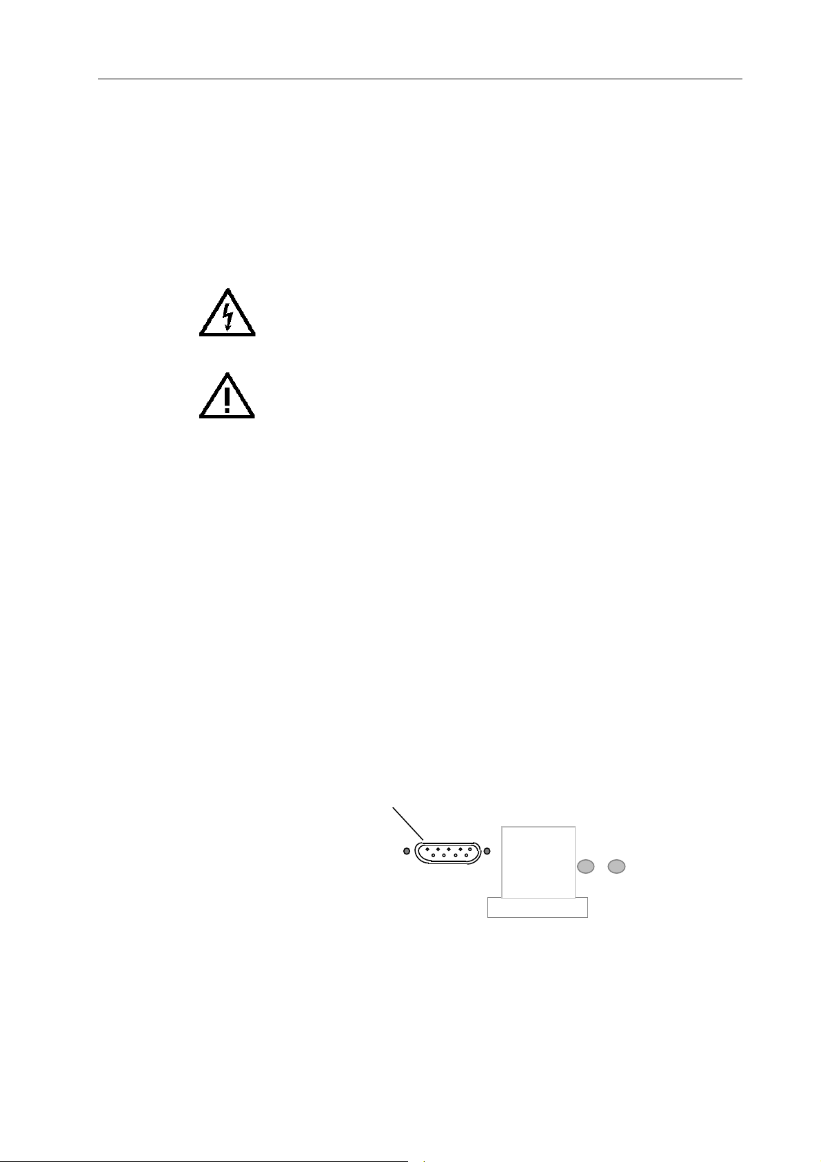
Explanation of safety related symbols and terms
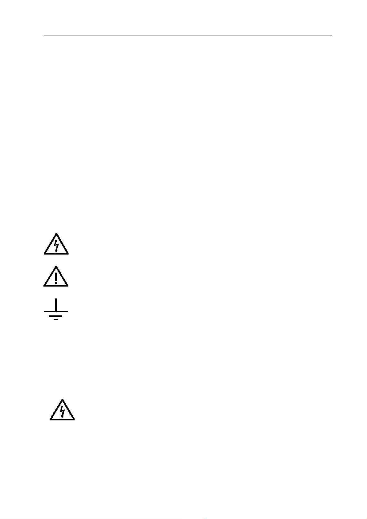
DANGER
Risk of Electric Shock The product is marked with this symbol to indicate that
hazardous voltage (> 30V dc or ac pk) may be present.
CAUTION
Refer to accompanying documents The product is marked with this symbol when it is necessary
for the user to refer to the instruction manual.
Earth (Ground) Terminal Functional Earth (Ground) only, must not be used as a
Protective Earth.
WARNING Warning statements identify conditions or practices that could result in injury or loss of life
CAUTION Caution statements identify conditions or practices that could result in damage to this or other
property.
WARNING
THIS INSTRUMENT CAN DELIVER A LETHAL ELECTRIC SHOCK. NEVER TOUCH ANY LEAD OR
TERMINAL UNLESS YOU ARE ABSOLUTELY CERTAIN THAT NO DANGEROUS VOLTAGE IS PRESENT.
ix
Page 12

Protective Earth (or Grounding)
Protection Class 1 - The instrument must be operated with a Protective Earth /Ground connected via the Protective
Earth/Grounding conductor of the supply cable.
This is connected to the instrument before the line and neutral connections when the supply plug is inserted into the
socket on the back of the instrument. If the final connection to the supply is made elsewhere, ensure that the ground
connection is made before line and neutral.
WARNING Any interruption of the protective ground conductor inside or outside the instrument is
likely to make the instrument dangerous. Intentional interruption is prohibited.
To avoid electric shock the signal connections to the instrument should be connected after the ground connection is
made and disconnected before the ground connection is removed, i.e. the supply lead must be connected whenever
signal leads are connected.
Do Not Operate without Covers
To avoid electric shock or fire hazard, the instrument must not be operated with covers removed. The covers protect
the user from live parts and unless otherwise stated they should be removed only by suitably qualified personnel for
maintenance and repair purposes.
WARNING Removing the covers may expose voltages in excess of l.5 kV pk; these may be present for
up to one minute after the instrument has been disconnected from the power source; longer
under fault conditions.
Safe Operating Conditions
The unit must be operated only within the manufacturers specified operating conditions. Examples of specification that
must be considered are:
Ambient temperature
Ambient humidity
Power supply voltage and frequency
Maximum terminal voltages or currents
Altitude
Ambient pollution level
Exposure to shock and vibration
To avoid electric shock or fire hazard, do not apply to or subject the instrument to any condition that is outside specified
range. Please refer to Appendix A of this manual for detailed Specification of the instrument and its operating
conditions.
CAUTION
Direct sunlight, radiators and other heat sources should be taken into account when
assessing the ambient temperature.
CAUTION
Before connecting the instrument to the supply, ensure that the rear panel AC supply voltage
selector is set to the appropriate voltage, either 115V or 230V and that correctly rated fuses
are fitted (see below)
Fuse Requirements
To avoid fire hazard the fuse arrangement shown in the table below must be followed. Additionally the supply network
must be fused at a maximum of 16 A and in the UK, a 5 A fuse should be fitted in the power cord plug.
x
Page 13

Power Input Fuse
Supply (Line)
Voltage
115 VAC
Fuse Action
T
Time delay
T
Time delay
Fuse Rating
UL/CSA
1 A
500 mA230 VAC
Wavetek-Datron
Part No.
2400-05-0029
2400-05-0010
Manufacturer
& Type No.
BUSSMAN MDL 1
BUSSMAN MDL 1/2
The Power Cord and Power Supply Disconnection
The power supply disconnect device is the ON / OFF switch on the rear panel of the instrument. The ON / OFF switch
should be readily accessible whilst the instrument is in operation. If this operating condition cannot be satisfied, it is
essential that either the power cord plug or a separate power disconnecting device be readily reached and accessible
to the operator.
To avoid electric shock and fire hazard, ensure that the power cord is not damaged and is adequately rated against power
supply network fusing. If the power plug is to be the accessible disconnecting device, the cord must not be longer than
3 metres.
Connection to Instrument Terminals
Ensure that the instrument is correctly Earthed (Grounded) via its power cord before and whilst any other connection
is made.
Installation Category I
Measurement and/or guard terminals are designed for connection at Installation (Over voltage) Category I. To avoid
electric shock or fire hazard the instrument terminals must not be connected directly to the mains power supply or any
other source of voltage or current that might temporarily exceed the peak ratings of the instrument
WARNING To avoid injury or loss of life, do not connect or disconnect signal leads while they are
connected, or suspected of being, connected to a hazardous voltage or current source
(internal or external to the instrument).
Maintenance and Repair
Local or national safety regulations and rules for the prevention of accidents and hazard must be observed in all work
performed. The unit must be disconnected from all signal sources and then the power supply before the removal of
covers. Any adjustment, parts replacement, maintenance or repair should be carried out only by authorised WavetekDatron technical personnel.
WARNING For continued protection against injury and fire hazard it is essential that only manufacturer
supplied parts be used to replace parts relevant to safety. Safety tests must be performed
after the replacement of parts relevant to safety.
Ventilation and Dust
The instrument relies on forced air cooling via a fan and ventilation slots. Adequate ventilation can usually be achieved
by positioning on a level surface and by leaving a 75 mm (3" gap) around the instrument. Care should be taken to avoid
restricting the airflow to or from the fan at the rear/sides of the instrument as damage may result from overheating.
Cleaning
Ensure the instrument signal and then power leads are disconnected prior to cleaning. Use only a damp, lint free cloth
to clean facia and case parts.
Observe any additional safety instructions or warnings given in this manual.
xi
Page 14
100 MHz Synthesized Arbitrary Waveform Generator model 395
987
4 5 6
1
0 • + /-
3
2
Model 395, 100 MHz Synthesized Arbitrary Waveform Generator
Page 15

Introduction
1.1 THE MODEL 395
Section 1
Wavetek-Datron’s Model 395 100-MHz synthesized arbitrary waveform
generator delivers high-speed performance in both bench-top
and ATE applications. The Model 395 combines the capabilities of a synthesized
arbitrary waveform generator, synthesized function generator, pulse generator, noise
generator, sweep generator, and trigger generator. As a modulation source, the Model
395 provides real-time AM and SCM, and synthesized AM, SCM and FM.
The Model 395’s 1mHz to 100 MHz clock generates arbitrary (user-defined) waveforms
with 12 bits of vertical resolution (4096 points: -2048 to +2047) and up to 256K points
of horizontal memory for simulating “real-world” non-standard signals. At clock rates
of 50 MHz or below, Model 395 uses direct digital synthesis (DDS) that provides highfrequency resolution (up to 10 digits). Model 395 is an excellent signal source for a wide
range of applications, including in-circuit testing of semiconductors, communication
testing requiring complex pulse patterns, and performance characterization testing of
electrical devices.
Create arbitrary waveforms using the Model 395’s front panel by using point-by-point,
copy, or line edit modes. Also, use the RS-232 interface or optional GPIB (IEEE-488.2,
SCPI compatible) interface to upload waveforms. Wavetek-Datron’s WaveForm DSP
software tool makes waveform creation, modification, and uploading easy over the
GPIB interface. The Direct DSO Upload, part of Option 001 IEEE-488 Interface, allows
transfer of waveforms captured with a digital storage oscilloscope directly into the
Model 395.
Another capability, Sequence, allows up to four waveforms to be linked in a sequence
with advancement from one waveform to the next conditional upon waveform repeat
(loop) counts and trigger signals.
In addition to complex arbitrary waveforms, Model 395 provides a number of synthesized
standard waveforms including sine waves to 40 MHz, square waves to 50 MHz, and
triangle waves to 10 MHz.
The built-in pulse generator generates pulses with programmable parameters that
include rate, width, delay, and rise/fall times. Pulse train allows you to create a series of
up to 10 independently programmable pulses each with their own level, width, delay,
rise/fall times.
Noise functions provide analog noise, digital noise, signal-plus-noise, comb, and combplus-noise.
Sweep allows frequency sweeps from 1mHz to 20 MHz in one continuous band and
include seven sweep modes, as well as linear or logarithmic spacing.
The Model 395 allows real-time AM and SCM modulation of both standard and arbitrary
waveforms.
For non-continuous operation, the Model 395 provides triggered and gated modes.
Triggered mode includes programmable burst counts from 1 to 1,048,575 counts.
Trigger sources include an internal trigger rate generator, manual trigger key, trigger
input BNC, and remote trigger command.
Model 395 is designed to provide an MTBF in excess of 10,000 hours, thus the Model
395 is extremely reliable. The easy-to-use calibration procedure can be performed
entirely from the front panel in less than fifteen minutes without removing the instrument
cover.
Introduction 1-1
Page 16

1.2 ORGANIZATION OF THIS MANUAL
Installation and Preparation For Use
Section 2 tells you how to set up and check out the Model 395 before you use it. It also
familiarizes you with the physical setup of the unit.
Introduction To The Model 395
Section 3 describes the fundamentals of front panel operation using a series of examples.
Operation Reference
Section 4 provides detailed explanations for every function and feature of the Model 395.
Remote Operation
Section 5 provides an introduction to the set up and operation of the Model 395 from
remote sources using the standard RS-232 or optional IEEE–488.2 interfaces. It also
contains the Model 395’s SCPI remote command set and IEEE-488.2 Common
Commands.
Specifications
Appendix A, located at the rear of this manual, contains the detailed specifications for
the Model 395.
Menu Quick Reference
Appendix B contains quick reference diagrams of the Model 395’s menu structure.
SCPI Quick Reference
Appendix C contains quick reference diagrams of the Model 395’s SCPI command tree.
The SCPI information is presented as a “Primer”. This appendix also contains the SCPI
required Conformance Information.
Rack Adapter Instructions
Appendix D contains instructions for mounting the Model 395 in an instrument rack.
DSO Upload
Appendix F contains instructions on DSO uploading to the Model 395. Plus, appendix
F describes how to create and load DSO driver files for DSOs not included in the unit’s
firmware.
Verification and Alignment Procedures
Appendix G contains both the verification test procedure and alignment procedure for
the Model 395.
1-2 Introduction
Page 17

Initial Preparation
2.1 THIS SECTION
This section contains:
Receiving and Inspecting Shipments;
Returning Equipment For Repair;
Preparation For Storage or Shipment;
Preparation For Use;
Initial Turn on;
Functional Checkout;
Routine Maintenance.
2.2 RECEIVING AND INSPECTING SHIPMENTS
Use the following steps to inspect a shipment of Wavetek-Datron equipment.
1. Inspect the shipment. If the shipment is damaged have the driver describe the box
damage and list shortages on the delivery bill.
If you find unreported shortages or damage, notify the shipper before further
unpacking.
2. After unpacking the boxes. Save all of the packing material.
Section 2
3. Inspect the equipment for damage. Inspect it carefully, regardless of the
condition of the shipping boxes.
4. If necessary, file a damage claim. If any damage is found, call the shipper within
10 days and start the claim process.
5. Call Wavetek-Datron. Call Wavetek-Datron’s Customer Service department
and tell them that the equipment arrived damaged.
2.3 RETURNING EQUIPMENT FOR REPAIR
Use the following steps if you should ever need to return the Model 395 to WavetekDatron for repair.
1. Save the packing material. Always return the equipment to Wavetek-Datron in
its original packing material and boxes. If you use inadequate packing material,
you will have to pay to repair any shipping damage. Carriers will not pay claims
on incorrectly packed equipment.
2. Call Wavetek-Datron for a Return Authorization. Wavetek-Datron’s customer
service representative will ask for the name of the person returning the equipment.
Plus, the representative will ask for your telephone number, company name,
equipment type and serial number, and a description of the problem.
Initial Preparation 2-1
Page 18

2.4 PREPARATION FOR STORAGE, SHIPMENT OR OPERATION
Packaging
If possible, always use the original shipping container. However, when using packing
materials other than the original, use the following guidelines:
Wrap the Model 395 in plastic packing material.
Use a double-walled cardboard shipping container.
Protect all sides with shock absorbing material (minimum of 2 inch thick
material) to prevent movement of the Model 395 within the container.
Seal the shipping container with approved sealing tape.
Mark “FRAGILE” on all sides, top, and bottom of the shipping container.
Storage
The Model 395 should be stored in a clean, dry environment. In high humidity
environments, protect the Model 395 from temperature variations that could cause
internal condensation. The following environmental conditions apply to both shipping
and storage;
Temperature –20°C to +70°C
Relative Humidity (sea level) Less than 95% at 11°C to +30°C.
Altitude Less 15,000 feet (4570 meters).
Vibration Less than 2g.
Shock Less than 40g.
Operation
The Model 395 should be operated on a flat surface or in an equipment rack within its
envoronmental specifications. All air vents should be clear of obstructions.
Signal connections should not be made to external hazardous voltages.
WARNING
THIS INSTRUMENT CAN DELIVER A LETHAL ELECTRIC SHOCK. NEVER
TOUCH ANY LEAD OR TERMINAL UNLESS YOU ARE FIRST
ABSOLUTELY CERTAIN THAT NO DANGEROUS VOLTAGE IS PRESENT.
SEE THE SAFETY ISSUES SECTION AT THE FRONT OF THIS MANUAL.
2.5 LINE VOLTAGES AND FUSES
The Model 395 accepts a primary input voltage of either 90 to 132 Vac or 198 to 252
Vac, 50/60 Hz. Wavetek-Datron ships the Model 395 set for the line voltage and with
the proper fuse for the destination country. Figure 2-1 illustrates the location of the line
voltage switch and fuse holder.
2-2 Initial Preparation
Page 19
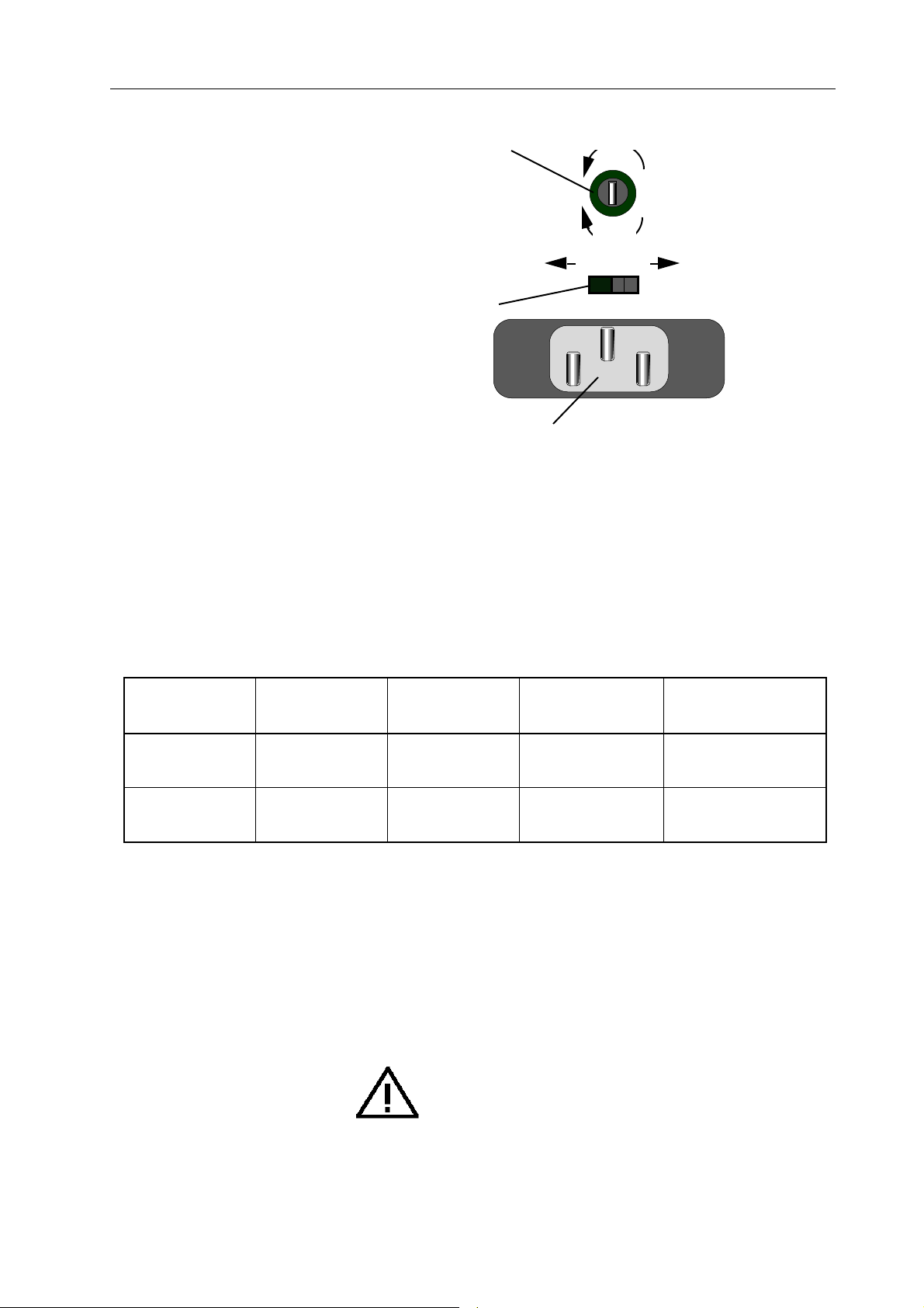
Fuse Holder
Remove
Install
230 115
Line Voltage
Selector
Power Connector
Figure 2-1. Line Voltage Switch and Fuse Holder
To change the line voltage, disconnect the power cord from the Model 395. Slide the
Line Voltage Selector (figure 2-1) to the desired line voltage: left for 230VAC, and right
for 115VAC. Refer to table 2-1 for voltage ranges for each voltage position. Also check
that the fuse is the correct rating; see the following procedure.
To change the fuse, perform the following steps:
1. Disconnect the power cord from the instrument. Remove the fuse from the fuse
holder.
Table 2-1. Line Voltage and Fuse Selection
Supply (Line)
Voltage
115 VAC
230 VAC
Fuse Action
T
Time delay
Fuse Rating
UL/CSA
1 A
Wavetek-Datron
Part No.
2400-05-0029
Manufacturer
& Type No.
BUSSMAN MDL 1
T
Time delay
2. Compare the ampere rating on the fuse to the ampere ratings given in table 2-1.
If the fuse is blown, replace it by sliding the new fuse back into the fuse holder.
If the fuse is not blown and has the right rating, keep it. If the fuse has the wrong
rating, place the new fuse into the fuse holder.
3. Connect the ac line cord supplied to the power connector at the rear of the unit
and power source.
CAUTION IN THE EVENT OF FAILURE OF ANY FUSE, CONTACT
500 mA
THE SERVICE CENTER IMMEDIATELY. SEE THE SAFETY
ISSUES SECTION AT THE FRONT OF THIS MANUAL.
2400-05-0010
BUSSMAN MDL 1/2
Initial Preparation 2-3
Page 20
2.6 INITIAL TURN–ON
WARNING
The Model 395 is equipped with a three-wire power cable. When
connected to a grounded AC power receptacle, this cable grounds the
instrument. Do not use extension cords or AC adapters without a
ground.
1. Connect the power cable supplied to the power connector on the Model 395 rear
panel; see figure 2-2.
Power Connector
Figure 2-2. Power Connector
WARNING
ANY INTERRUPTION OF THE PROTECTIVE EARTH/GROUND
CONDUCTOR INSIDE OR OUTSIDE THE INSTRUMENT IS LIKELY
TO MAKE THE INSTRUMENT DANGEROUS. SEE THE SAFETY
ISSUES SECTION AT THE FRONT OF THIS MANUAL.
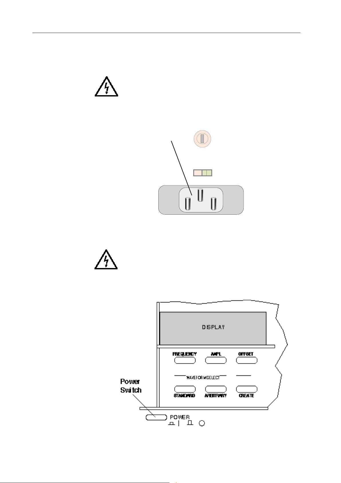
2. Press the “POWER” On/Off switch in to turn the unit on (figure 2-3).
2-4 Initial Preparation
Figure 2-3. Power Switch
Page 21

2.7 ERROR MESSAGES
Some front panel entries may cause error or information messages to appear on the
display.
2.8 FUNCTIONAL CHECKOUT
The functional checkout provides a quick method of verifying the Model 395 operation.
The only test equipment required is an oscilloscope (Tektronix 2445 - dual channel or
equivalent), and the appropriate cables and loads.
Continuous Mode Check
1. Connect the Model 395 to the primary power source. Leave all cables
disconnected. See Initial Turn-On in this section.
2. Turn on the Model 395 by pushing in the POWER switch.
At power on, the Model 395 displays its start up screen (figure 2-4).
Wavetek
Model 395
(for assistance,
press HELP)
3. Press the RESET key, and from the Instrument Reset screen press F3 to reset all
parameters. Then press F8 to confirm reset.
4. Press the MAIN OUT key to turn on the Main Output. Main Out indicator
remains on.
5. Press the SYNC OUT key. From the Sync Output Setup screen, press F2 twice
to turn the Sync Output on (“output: on”).
Observe: Scope displays a 1Vp sine wave at 1kHz (Main Out must be terminated
into 50Ω).
Sweep Mode Check
Press the MODE key. From the Mode screen, press F2 “sweep.”
Observe: Scope displays a sweep of the frequency from 1kHz to 10 kHz.
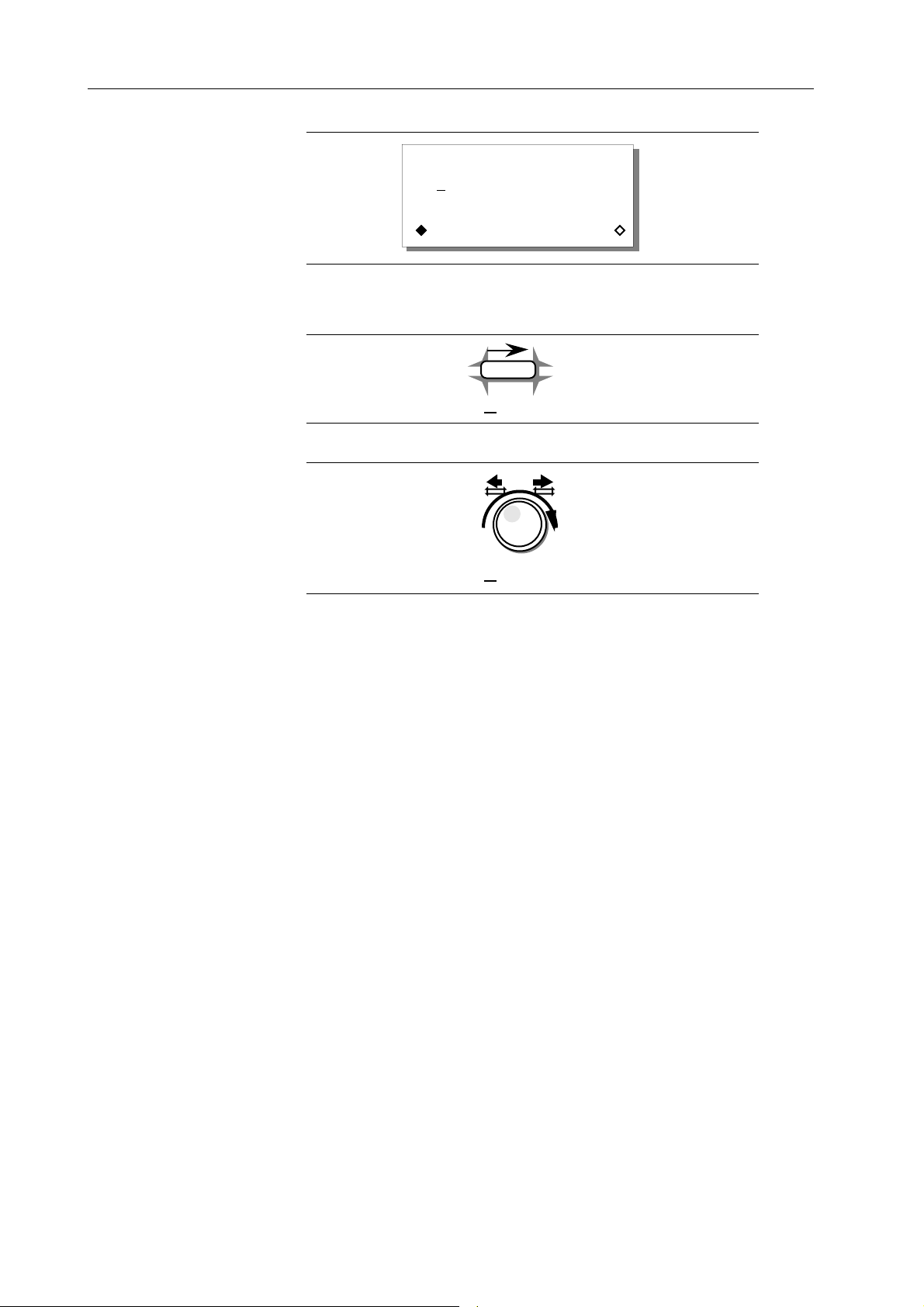
Gated Mode Check
Press the MODE key. From the Mode screen, press F3 “gated.” Press the
STANDARD key, and then rotate the knob; select the softkey to select
“triangle.”
This check uses the Model 395’s internal trigger source which is programmed
to 5 ms.
Observe: Scope displays a gated waveform; see below:
Figure 2-4. Model 395 Start Up Screen
1ms
5ms
Initial Preparation 2-5
Page 22

Triggered Mode Check
Press the MODE key. From the Mode screen, press F4 “trig’d.”
This check uses the Model 395’s internal trigger source which is programmed to
5 ms.
Observe: Scope displays a triggered waveform with a count of 1; see below:
This completes the functional test. Remove all cables and test equipment.
2.9 OPERATOR MAINTENANCE
2.9.1 Routine Maintenance
No tools or equipment are required for routine maintenance. Cleaning materials
required are listed below:
Description National Stock Number
Cotton Cheesecloth 8305-00-267-3015
Mild Liquid Detergent None
Routine maintenance for the Model 395 is limited to routine tasks such as listed below;
Cleaning, using cloth moistened with detergent
Dusting,
Wiping,
Checking for frayed cables,
Storing items not in use,
Covering unused receptacle,
Checking for loose screws.
Perform these routine tasks as required.
5ms
CCC-C-440, Type II,
Class 2 (81349)
2-6 Initial Preparation
Page 23
2.9.2 Battery Replacement
The Model 395 contains an internal battery for the unit’s internal memory. Its replacement
should only be carried out by a suitably qualified technician. Measure the battery voltage
when performing calibration of the unit (approximately every 12 months); refer to
paragraph 4.3, figure 4-7 and table 4-6 item 6. The battery should measure between +3.2
Vdc and +2.7 Vdc. Replace the battery when it measures +2.7 Vdc or below to avoid
loosing Arb waveforms, stored settings, “last setup,” and all remote setup parameters.
This instrument uses an internal battery containing more than 0.2
grams of Lithium. Do not charge or short this battery. A hazard of
explosion and or contamination exists.
CAUTION Always replace the battery with one of the same type: Panasonic BR-
2/3A
To replace the battery. This task should only be undertaken by a suitably qualified
technician.
1. Turn off the Power and disconnect the power cable.
2. Remove the two screws; one on each side of the cover.
3. Slide the cover back.
4. Remove the battery.
5. Remember, removing the battery will loose Arb waveforms, stored settings,
“last setup," and all remote setup parameters.
6. Install the new battery. Be sure to match the polarity on the battery with the
polarity indicator on the battery holder.
WARNING
2.10 RACK MOUNTING EARS
The Model 395 can be rack mounted using the optional mounting ears (Option 004).
Installation instructions are in appendix D of this manual.
2.11 REMOTE SETUP
2.11.1 RS-232
To connect the Model 395 to a computer via RS-232, use the provided RS-232 cable. For
information on RS-232 remote programming, refer to section 5 of this manual. Note that
the 0 V connection on the RS–232 connector is internally connected to the floating
analog common and not ground.
RS-232
Connector
CAL ENABLE
RS-232
NORM - CAL
Cal Sticker
Figure 2-5. RS-232-C Connector
BATTERY
TEST
BAT GND
Initial Preparation 2-7
Page 24
Standard RS-232 Connection
The Model 395 is configured as a DCE , and uses a 9-pin female connector (DB-9). The
standard connection will be to a DTE ( generally a computer) with a standard 9-pin male
connector (DB-9). This connection can be made using the 9-pin female to 9-pin male
cable (P/N 6001-00-0061) included with the Model 395. If the DTE uses a male DB-25,
the connection can be made using the 25-pin female to 9-pin male adapter (P/N 210002-0328 ) included with the Model 395. After connections are made, both the Model 395
and the DTE must be configured to have the same baud rate and data format. The data
format for the model 395 is 8-bits, no parity, one stop bit. Refer to section 5.3 for the
Model 395 RS-232 setup.
Non-Standard RS-232 Connection
Because the Model 395 is configured as a DCE, connection to a device configured other
than a standard DTE may require a special cable. Some knowledge of the RS-232 is
beneficial to insuring a proper connection. The pin assignments for the model 395 and
for a standard DTE (an AT comm port), are given in Table 2-2 .
EIA STANDARD RS-232-C specifies the electrical characteristics and pinouts of a
serial communication standard for connecting “Data Terminal Equipment” (DTE) to
“Data Communication Equipment” (DCE). A DTE is usually a device such as a
terminal, computer, or printer, that is the final destination of data. A DCE is usually a
device that converts data to another form and passes it through such as a modem.
Because RS-232 signal lines defined as outputs on a DTE are inputs on a DCE and vise
versa, connection of a DTE to a DTE or a DCE to a DCE requires a special cable with
many of the lines interchanged. Generally a “Null Modem” cable will have the correct
lines interchanged.
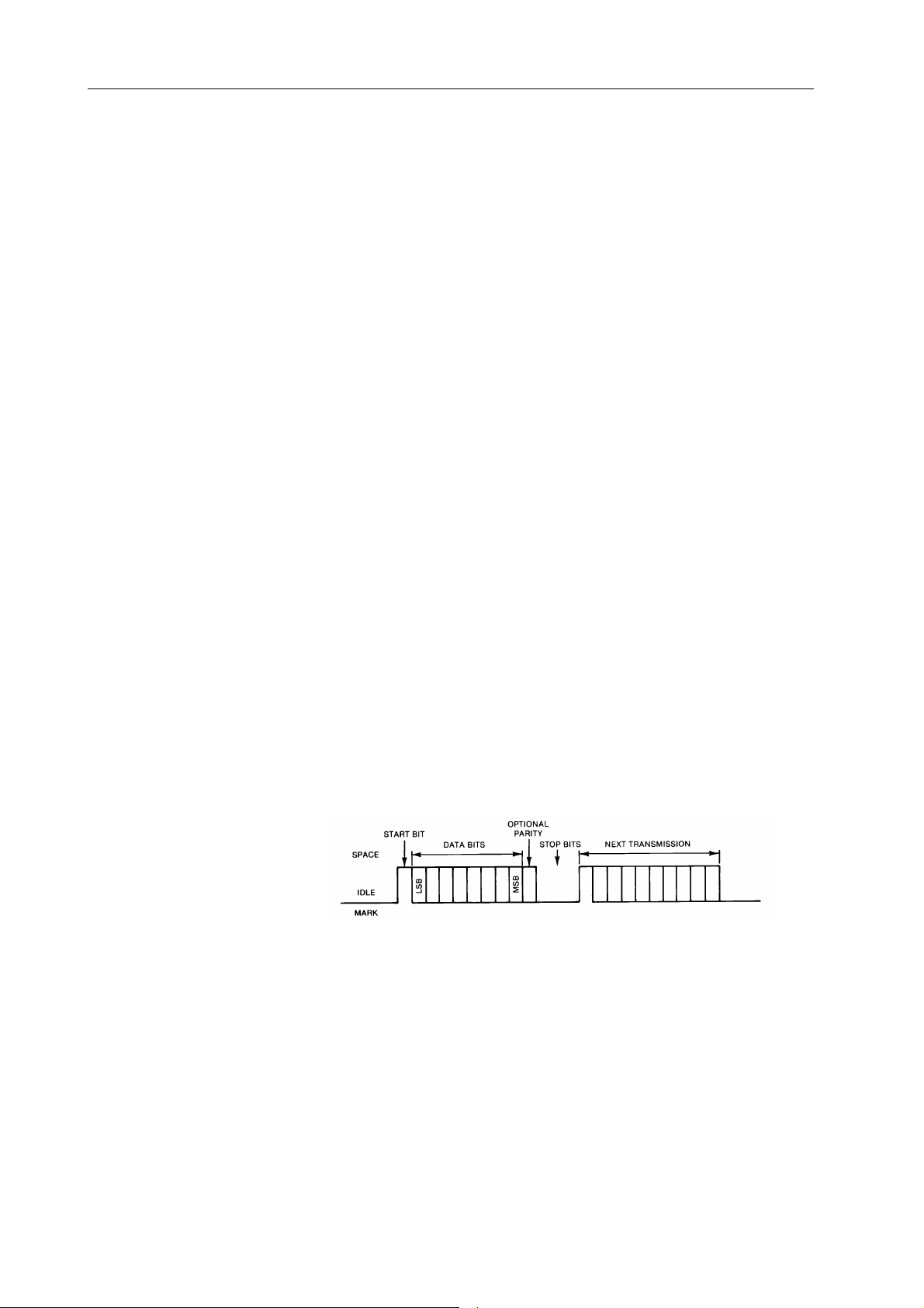
With RS-232-C, data is transferred serially between two devices using a voltage of +3
to +25 Vdc to represent a zero ( space ), and a voltage of -3 to -25 Vdc to represent a one
( mark ). Only two lines are required to transfer data, transmit and receive. When no data
is being transferred, these lines will be at a mark state. To transmit a byte, the
transmitting device first sends a start bit , a space, to synchronize the receiver. Then, the
data bits are sent LSB first (eight bits for 395). Some devices follow the data bits with
a parity bit (not 395). At the end there is up to 2 stop bits (395 uses one stop bit) that are
at the mark state.
The rate at which the bits are transferred is called baud rate and is in bits per second. The
baud rate must be set the same for both devices. The 395 has seven different baud rates
ranging from 1200 to 57.6K.
Handshaking is a communication between the two devices to control the transfer of data
to insure no data is lost when the data is transferring faster than a device can process it.
Handshaking can be accomplished in two ways, software or hardware. Software
handshaking is done using XON / XOFF protocol (not supported by 395), which sends
control characters over the data lines to control the flow.
2-8 Initial Preparation
Page 25

Hardware handshaking uses additional lines ( DSR, DTR, RTS, CTS) to signal when the
device is ready to receive data. These handshake lines use +3 to +25 Vdc to indicate a
true, and -3 to -25 to indicate a false condition. When a DTE is ready to communicate,
it drives the DTR line true. The DCE (395) will respond by driving the DSR line true.
Then the DTE will drive RTS true when it is ready to receive data and the DCE will drive
CTS true when it is ready to receive data.
Table 2-2a. Model 395 RS-232 Connections (DB-9)
Pin Name Direction Description
1 DCD OUT Carrier Detect
2 RxD IN Receive Data
3 TxD OUT Transmit Data
4 DTR IN Data Terminal Ready
5 GND COMMON Signal Ground
6 DSR OUT Data Set Ready
7 RTS IN Request To Send
8 CTS OUT Clear To Send
9 NC - - - No Connection
Table 2-2b. Standard DTE RS-232 Connections
Pin Name Direction Description
DB-9 DB-25
1 8 DCD IN Carrier Detect
2 3 RxD IN Receive Data
3 2 TxD OUT Transmit Data
4 20 DTR OUT Data Terminal Ready
5 7 GND COMMON Signal Ground
6 6 DSR IN Data Set Ready
7 4 RTS OUT Request To Send
8 5 CTS IN Clear To Send
9 22 RI IN Ring Indicator
The Model 395 RS-232 signal names are defined below. A positive voltage above
+3Vdc is defined as a logic ‘0’ or ‘ON’. A negative voltage below -3 Vdc is defined as
a logic ‘1’ or ‘OFF’.
DCD Internally connected to pins 4 (DTR) and 6 (DSR) in the model 395. A logic ‘0’
signifies that the 395 is ready for communication. See notes for DTR.
TxD Serial data output from Model 395.
RxD Serial data input to Model 395.
DTR Signal from a DTE that indicates it is ready for communication. This signal is
internally connected to pins 1 (DCD) and 6 (DSR). Upon receipt of a logic ‘0’,
the DCD and DSR are driven to logic ‘0’ thus signaling that the 395 is ready for
communication.
GND Connected to internal signal ground. This should be connected to a ground point
on the device that the 395 is going to communicate with for proper error free
operation.
Initial Preparation 2-9
Page 26

DSR Internally connected to pins 1 (DCD) and 4 (DTR) in the model 395. A logic ‘0’
signifies that the 395 is ready for communication. See notes for DTR.
RTS A logic ‘0’ on this pin indicates that the device that is connected to the 395 is ready
to receive data. When handshaking is disabled, this line is ignored by the 395.
The length of time that the 395 will wait before aborting transmission can be set
in the RS-232 setup screen (see section 5). The Model 395 will respond to a logic
‘1’ with a transmission latency of one character.
CTS A logic ‘0’ indicates that the Model 395 is ready to receive data. When
handshaking is enabled, this line is driven to logic ‘1’ when the 395 receive buffer
is about 2/3 full. Data will continue to be stored in the buffer until it is full. This
line will be driven to a logic ‘0’ when the buffer drops below 2/3 full. To prevent
data loss, this line should be connected and recognized by the other device.
NOTES:
Although communication can be accomplished using only the Transmit
and Receive lines, it is recommended that the ground and handshake
lines are connected so no data is lost due to the high transfer rates
possible with the Model 395.
Software handshaking ( XON / XOFF ) is not supported by the Model
395.
The Model 395 data format is 8 data bits, no parity, 1 stop bit.
2.11.2 IEEE-488 (Option 001)
To connect the Model 395 via the IEEE-488 interface to a computer or digital storage
oscilloscope, DSO, (figure 2-6), use a standard IEEE-488 bus cable [Wavetek-Datron
part number 630364 (1 metre) or 630366 (2 metres)]. For more information on remote
programming using IEEE-488, refer to section 5 of this manual.
IEEE-488
CAL ENABLE
BATTERY
NORM - CAL
Cal Sticker
TEST
BAT GND
Figure 2-6. IEEE-488 Connector
Note that the 0 V connection on the IEEE-488 connector is internally connected to the
floating analog common and not ground.
Connector
2-10 Initial Preparation
Page 27

3.1 OVERVIEW OF THE MODEL 395
The Model 395, 100 MHz Synthesized Arbitrary Waveform Generator, produces
a variety of standard, pulse, noise, and user-defined (Arbitrary) waveforms. In
addition, the Model 395 allows linking of up to four arbitrary waveforms to form
a Sequence. Plus, the Model 395 triggers, sweeps, and modulates all waveforms.
Also, sum an external signal with the generator’s internal signal.
The Model 395 stores up to 100 Arbitrary waveforms in battery-backed memory.
Complete instrument setups can be stored and recalled.
Using the Model 395
Section 3Introduction To The Model 395
This section introduces front panel operation of the Model 395. Included in this
section are a series of examples demonstrating the features of the unit. Section 4
contains reference information about Model 395 operation. Section 5 describes the
SCPI remote programming commands, RS-232 operation, and optional IEEE 488
operation. Section 5 also contains a series of SCPI language remote programming
examples demonstrating the unit’s features; these examples are the remote
programming equivalent of the examples in this section.
Appendix B of this manual contains a front panel screens quick reference, while
appendix C contains SCPI commands quick reference.
3.2 NAVIGATING THE SCREENS
3.2.1 Front Panel Keys and Screens
Pressing front panel keys display screens with program parameters relative to the
key pressed. Change program parameters by using softkeys (F1 through F8), or
change numeric values using the keypad or knob. For example, press the
FREQUENCY key to display the Frequency screen; see figure 3-1.
Introduction To The Model 395 3-1
Page 28
Try pressing the TRIG IN key or MODE key to display their screens.
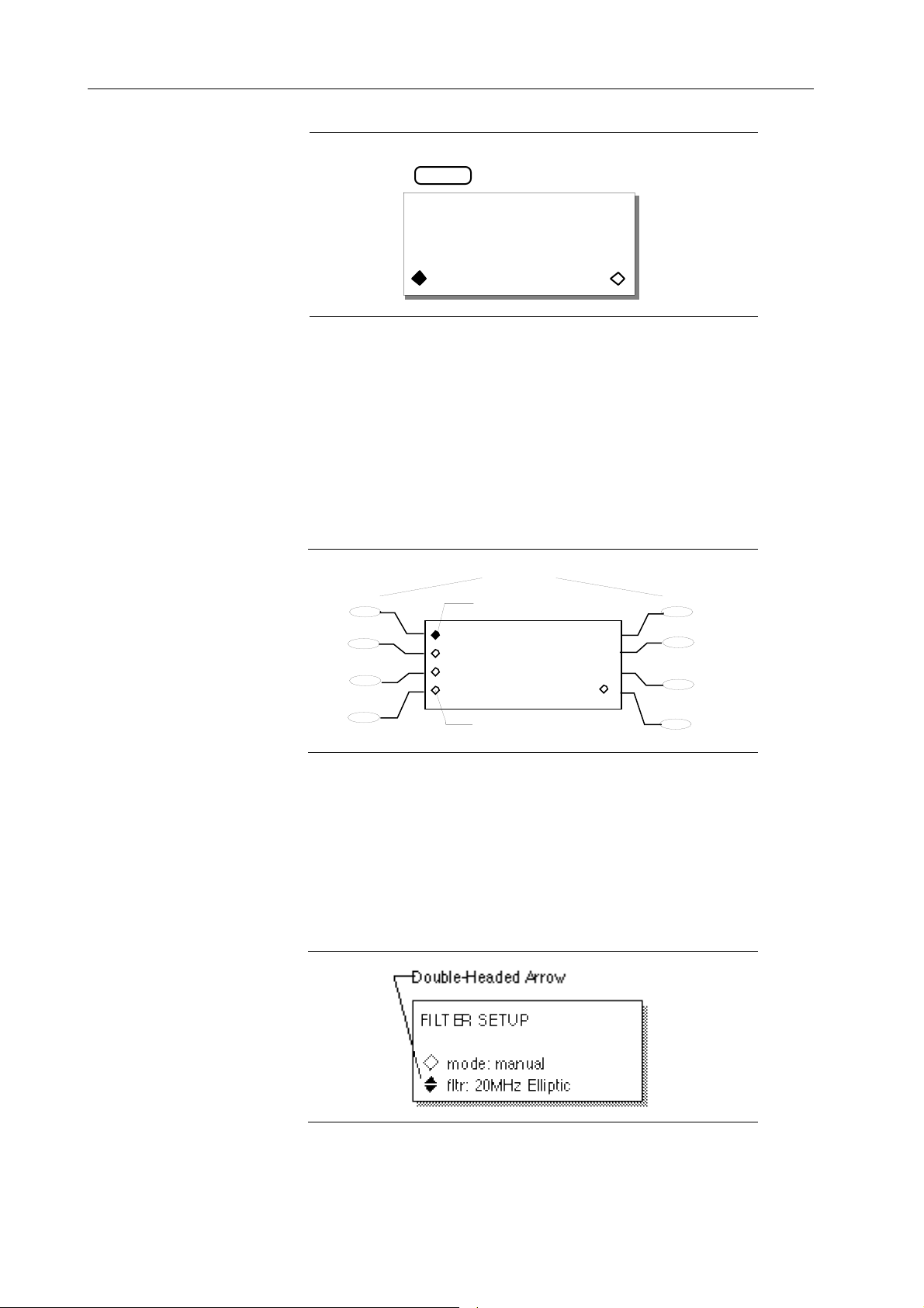
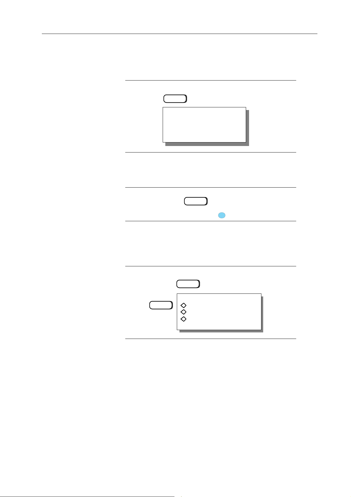
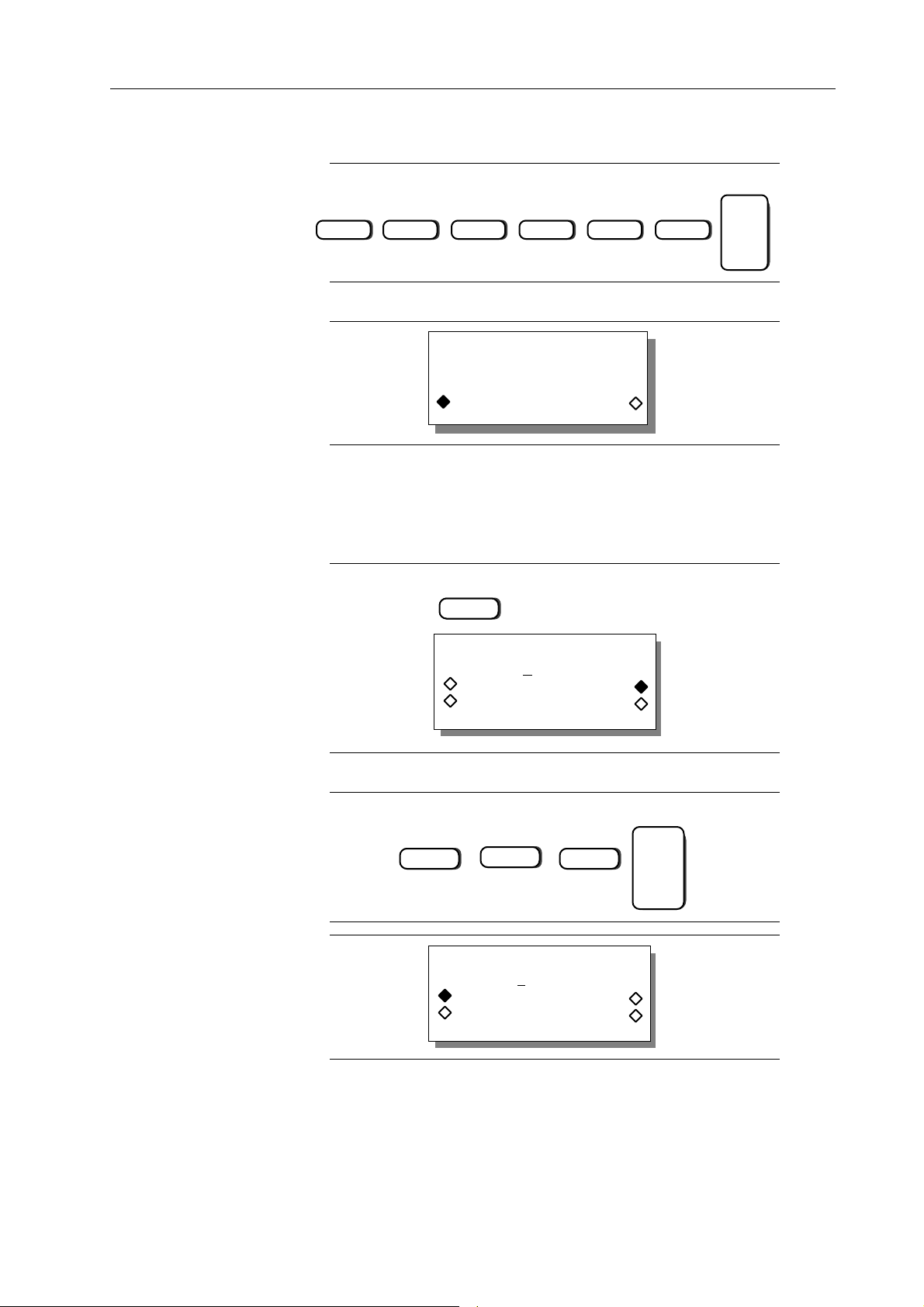
3.2.2 Softkeys
The Model 395 front panel softkeys (F1 through F8) allow you to select items from the
screen (figure 3-2).
Diamonds on the screen identify selectable screen items. Hollow diamonds identify
deselected items. Filled diamonds denote selected items. For example, press MODE
and then press F3 to select the “gated” mode (figure 3-2). Default items are initially
displayed with filled-in diamonds (like continuous in figure 3-2).
F1
F2
F3
F4
FREQUENCY
STANDARD FREQUENCY
1.000000000 kHz
freq period
Figure 3-1. Frequency Screen
Softkeys
Selected Item
continuous
sweep
gated
trig'd, cnt:0000001
Unselected Item
F5
F6
F7
F8
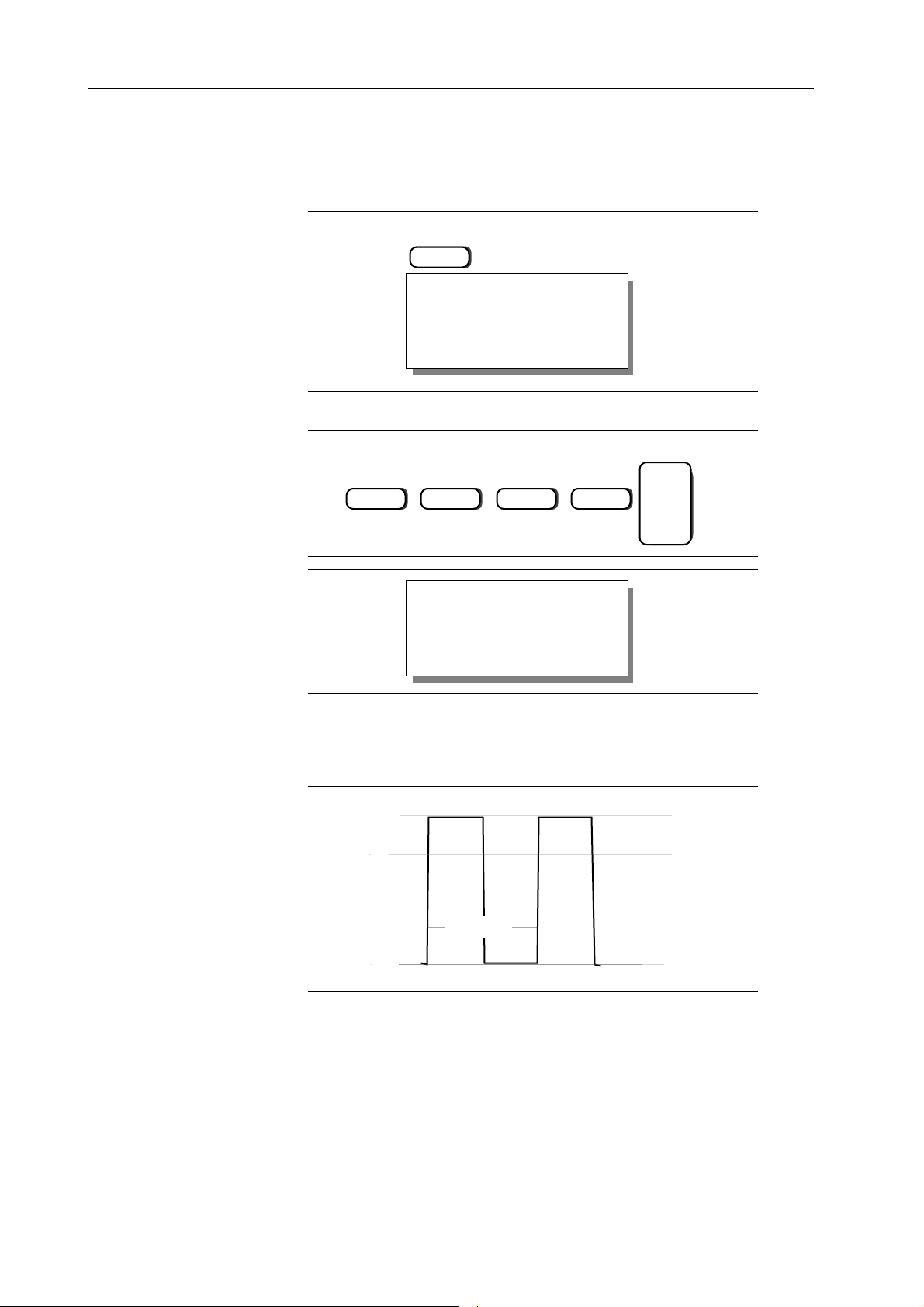
3.2.3 Extended Screens
Double-Headed Arrows
Double-headed arrows on the screen indicate additional screen items can be accessed by
using the knob or the cursor keys. See figure 3-3. Also, items next to double-headed
arrows also can be selected by using the softkey.
Figure 3-3. Double-Headed Arrow (Filter Screen)
Figure 3-2. Softkeys (Mode Screen)
3-2 Introduction To The Model 395
Page 29
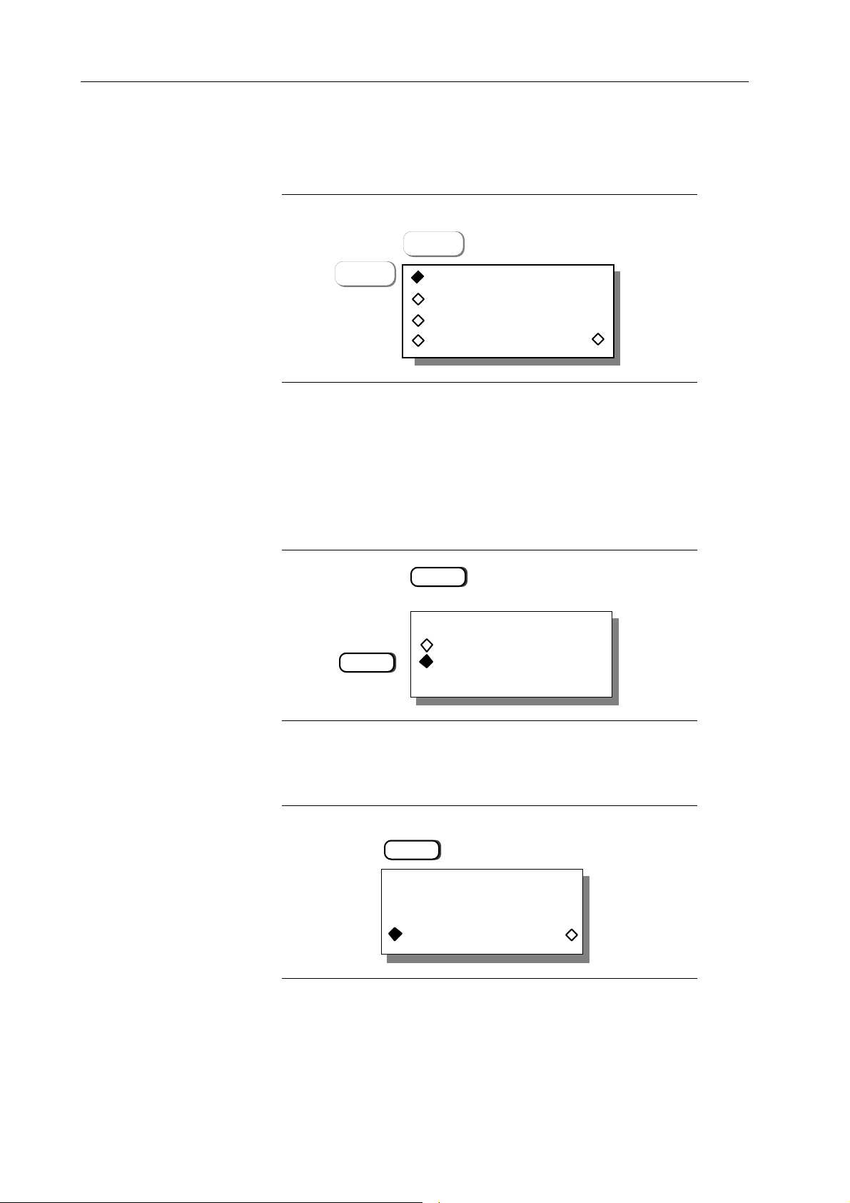
… Ellipsis
CREATE NEW WAVEFORM
(avail mem: 64512)
create blank …
create from copy …
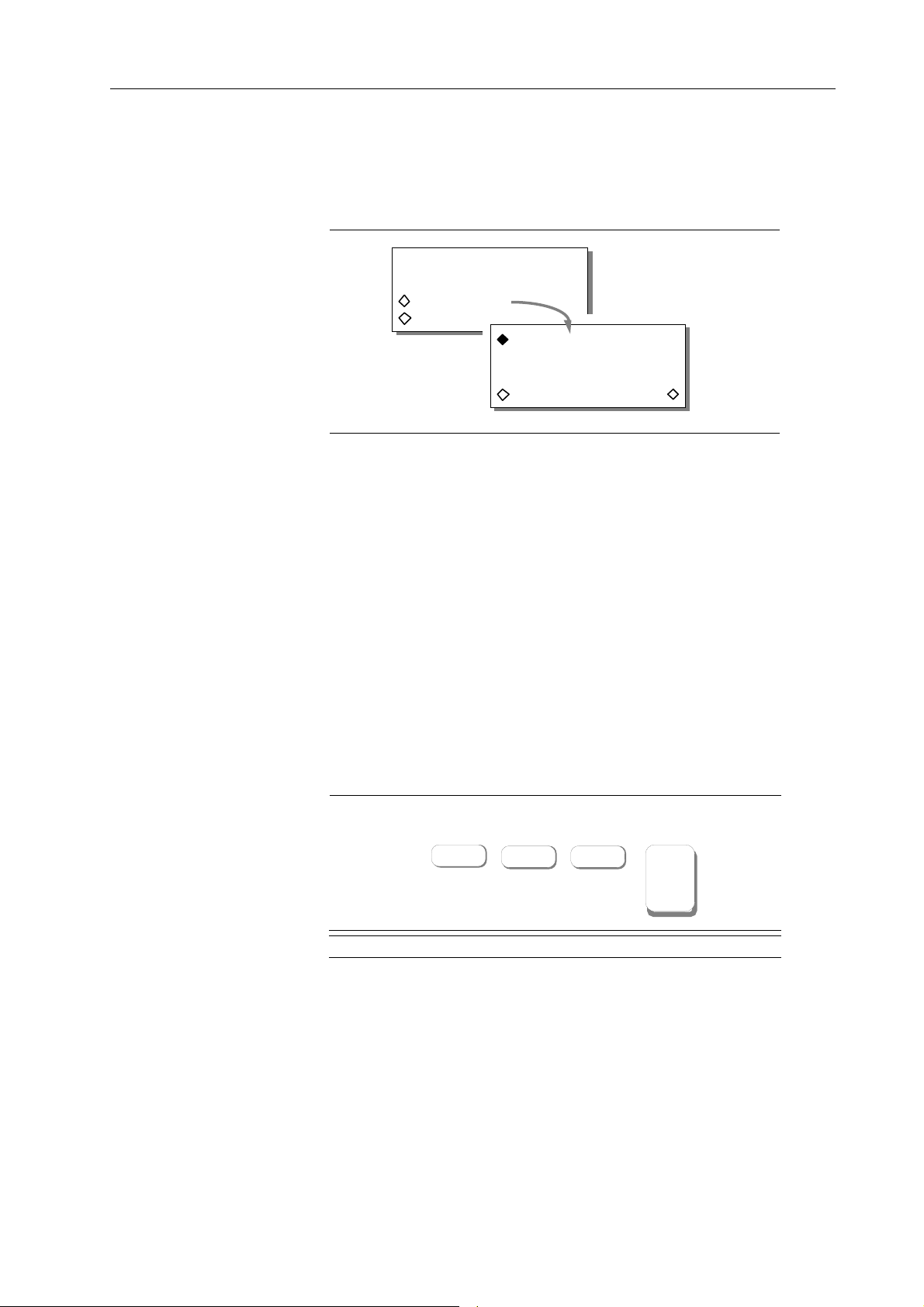
An ellipsis (three dots following screen text) indicates additional screens will follow
when selected. For example, press the Waveform Edit’s CREATE key and check out
“create blank …,” see figure 3-4.
Figure 3-4. “Ellipsis” (Create Screen)
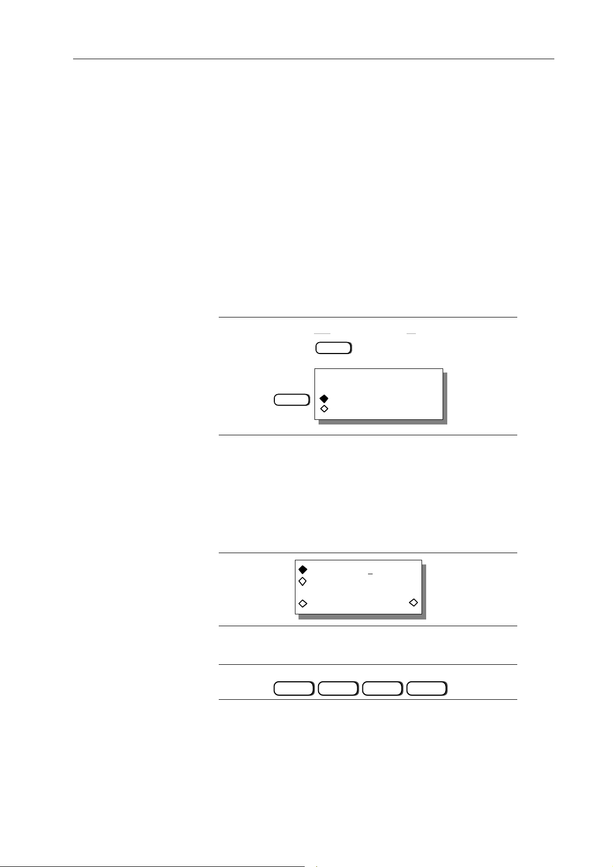
3.2.4 Changing Numeric Values
The Model 395 allows you to change numeric values using the numeric keypad or knob.
The screen displays modifiable values with the “cursor” starting under the most
significant digit. For example, try pressing the OFFSET key.
With the Keypad
CREATE: "wv2_____"
size: 1024
(max: 64512)
cancel create
To enter values using the keypad, press the numeric key. The Model 395 accepts the
value when the Enter key is pressed.
The Model 395 accepts values in three basic formats: Integer (10), floating point (10.0),
and exponential (1 exp 1).
For example, to change the frequency to 50 kHz using the exponential format, enter the
value by pressing these keys:
5
EXP
4
ENTER
50.00000000 kHz
Using the Knob
The front panel knob also can be used to change numeric values. When using the knob,
values are always changed starting from the digit over the cursor. To modify a value
using the knob, place the cursor under the desired digit, and rotate the knob to change
the value. Clockwise rotation increases the value; and counterclockwise rotation
decrease the values.
For example, to use the knob to set the frequency to 50.35 kHz, press the FREQUENCY
key to display the Standard Frequency screen; see figure 3-5. Note: the number of digits
shown on the frequency screen depends on the selected waveform.
Introduction To The Model 395 3-3
Page 30
STANDARD FREQUENCY
50.00000000 kHz
freq period
Figure 3-5. Knob Example
Use the right “cursor” key to move the cursor over three digits.
3X
50.00000000 kHz
Rotate the knob clockwise until the frequency reads 50.35000000 kHz.
50.35000000 kHz
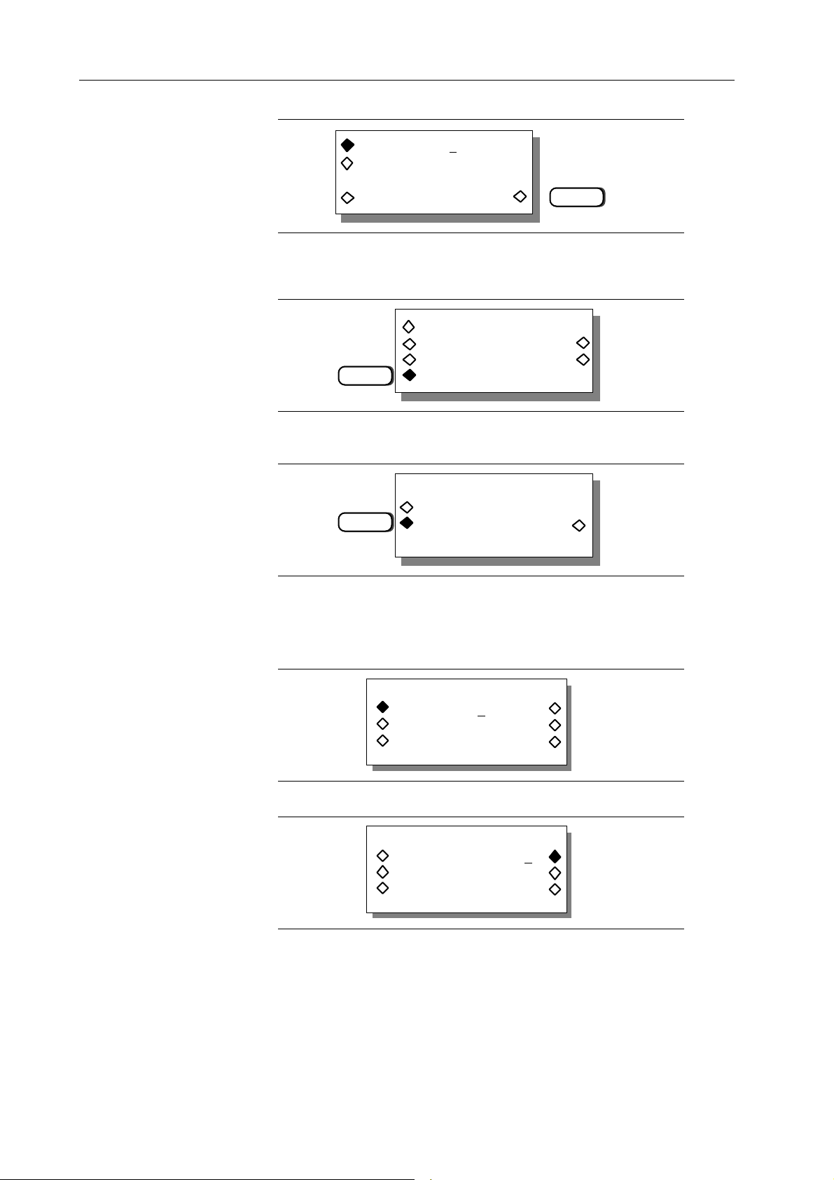
3.2.5 Correcting Mistakes
3.3 ON-SCREEN HELP
If you make a mistake while entering a value from the front panel, you can make
corrections by using the CLEAR key or the BSP (Backspace) key.
Use the CLEAR key to erase the entire value. Pressing ENTER, rotating the knob, or
pressing a cursor key, restores the original value providing a value has not been entered
via the keypad.
When using the keypad to enter values, press the ¨ BSP (backspace) key to erase the digits
to the left of the cursor. Then use the keypad to enter the correct value.
The Model 395 includes on-screen help for the current screen. To access a Help screen,
press the HELP “button;” see figure 3- 6. Rotate the knob or use the cursor keys to display
additional help lines. Press the HELP key a second time to return to the operation screen.
3-4 Introduction To The Model 395
Page 31

STATUS
For example, press the AMPLITUDE key and then press the HELP key; see below figure
3-7 .
3.4 ERROR MESSAGES
When the Model 395 detects an operational error, it displays a message describing the
problem. Press any key to remove the error message and return to the operation screen,
.
ERROR messages occur if you attempt an illegal operation, such as setting the amplitude outside
the range supported by the instrument. For example if you try to program an amplitude of
6 Vp, you will see the message shown in figure 3-8.
HELP
Figure 3-6 . Help Key
--AMPLITUDE HELP-use knob to scroll
help message
------------------------------------
Figure 3-7 . Amplitude Help Screen
3.5 Initial Setup
Before operating the Model 395, connect the Model 395 to the correct AC power source;
see section 2 - Initial Turn-On.
Make sure the fuse in the instrument matches the fuse required for your primary power
source voltage. See Section 2, Preparation for Use, Fuse Replacement. Also, be sure
the specified line voltage of the unit matches the primary power source. Use the power
cord supplied with the unit to connect the Model 395 to the primary power source.
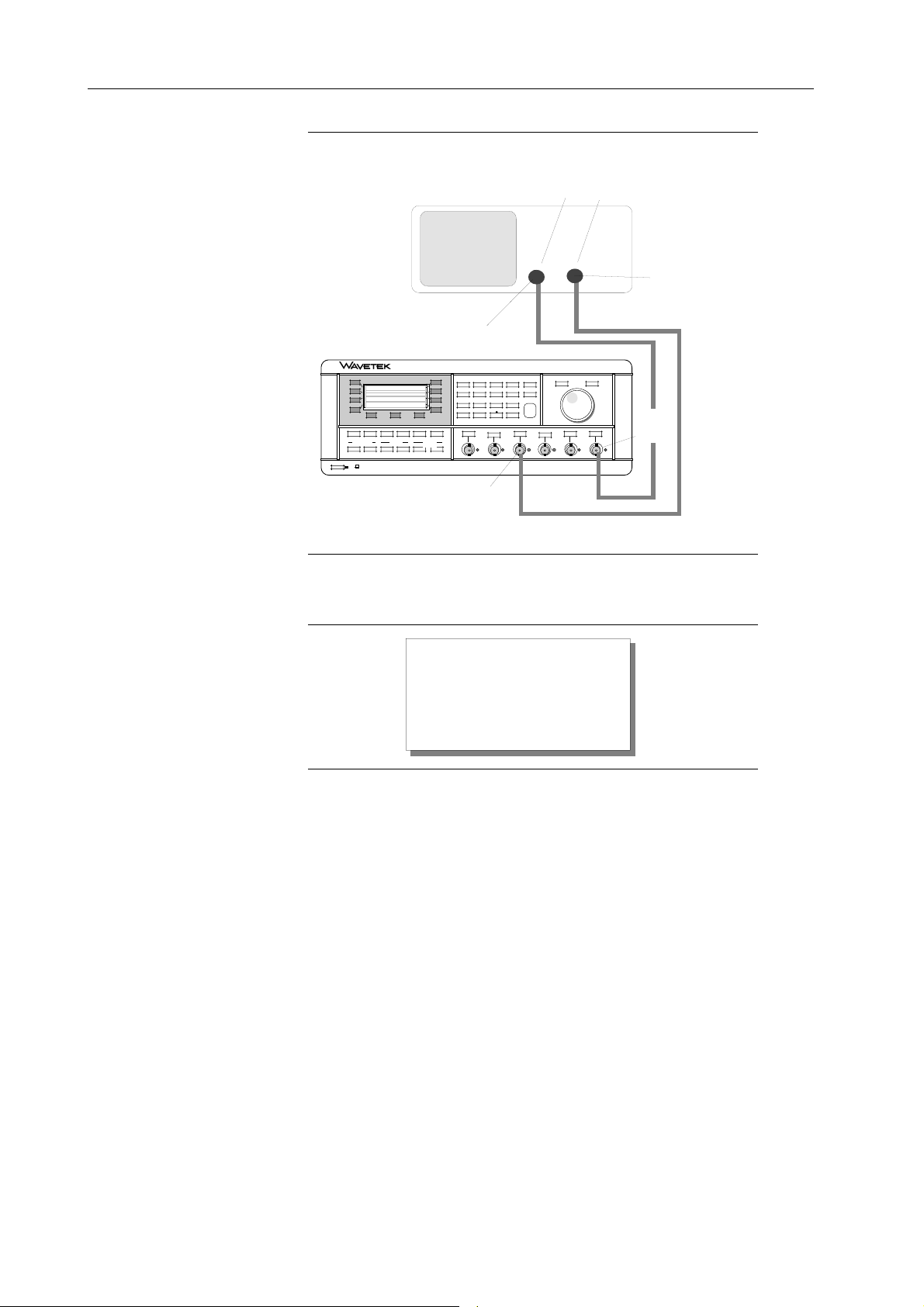
Use the correct cables and terminations to connect the Model 395 to an oscilloscope.
Figure 3-9 illustrates a typical setup that connects the Model 395 Main Out to channel
1 on the oscilloscope, and the Sync Out to the scope trigger input. Cables from both
outputs must be terminated with 50Ω. Some scopes contain built-in 50Ω terminations.
DATA OUT OF RANGE:
min value 0
max value 5
<press ENTER>
Figure 3-8 . Error Message Sample
Introduction To The Model 395 3-5
Page 32
Oscilloscope
Channel 1
Input
Trigger
Input
50Ω
Termination
50Ω
Model 395
F1
F2
F3
F4
DISPLAY
FREQUENCY
WAVEFORM SELECT
POWER
ON OFF
OFFSET SEQUENCEMODE
AMPL
CREATE MODIFY
Termination
100 MHz Arbitrary Waveform Synthesizer Model 395
F5
F6
F7
F8
STATUSHELP
FILTER
WAVEFORM
INSTRUMENTS
EDIT
UTILITYSTANDARD ARBITRARY
SETUPS
RESET
REMOTE
MAN TRIG
BSP
7 8 9
4 5 6
1 2 3
0
TRIG IN
2kΩ
(0-10V)
CLEAR
EXP
ENTER
+/-
SYNC OUT
2kΩ
(±10V)
SUM IN MAIN OUT
AM INSWEEP OUT
50Ω
2.5kΩ
(TTL)
600Ω
(5Vpp)
(10Vpp)
Main
Out
50Ω
(10Vpp)
Sync
Out
Figure 3-9. Model 395 to Scope Interconnection
When the Power is turned on, the Model 395 displays its start-up screen (figure 3-10).
Wavetek
Model 395
(for assistance,
press HELP)
Figure 3-10. Model 395 Start-up Screen
3.6 MODEL 395 AS A FUNCTION GENERATOR
As a function generator, the Model 395 generates sine, square, triangle, positive ramp,
negative ramp, positive haversine, negative haversine, sin(x)/x, and dc waveforms.
Example 1. Setting Up the Function Generator
This example illustrates how to set up the Model 395 to produce a continuous, 4.58 MHz,
5.4 Vp-p square wave with a -1.2 Vdc offset. Paragraph 5.5.1, example 1 contains the
remote SCPI programming equivalent of this example. To view the signal on an
oscilloscope, connect the Model 395 to the scope as described in paragraph 3.5. This
example is the front panel equivalent of example 1, paragraph 5.5.1.
3-6 Introduction To The Model 395
Page 33
Step 1 Initial Setup and Power On
Connect the Model 395 to a power source - see paragraph 2.6 Initial Turn-On. Push the
POWER switch in. The Model 395 displays its start-up screen.
STEP 2. ENABLING THE MAIN OUT
To output the signal generated by the Model 395, you must enable the output by pressing
the MAIN OUT key. A lit indicator lights indicates the output is on.
POWER
Wavetek
Model 395
(for assistance,
press HELP)
MAIN OUT
ON
If a scope is connected to the Main Out, you will see a waveform on the scope screen.
Step 3 Synchronizing the Scope and Model 395
To synchronize the scope signal with the Model 395, press the SYNC OUT key to
display the Sync Output Setup screen:
SYNC OUT
F2
Enable the Sync Out signal by pressing F2 “output” until “output: on” appears. The Sync
Out indicator lights.
SYNC OUT SETUP
output: off
mode: auto
src: waveform sync
Introduction To The Model 395 3-7
Page 34
Step 4 Selecting Continuous Mode
Mode defines the operating state (continuous, triggered, etc.) of the Model 395. To set
the operating mode to continuous, press the MODE key to display the mode screen:
MODE
F1
continuous
sweep
gated
trig'd , cnt: 0000001
Press F1 “continuous” to selected this mode. Continuous is the default mode.
Step 5 Selecting Square Wave
Select a waveform by pressing the STANDARD key under Waveform Select to display
the Waveform screen. Select the square wave by pressing the softkey (initially F3) to
the left of “square.”
If square is not shown on the screen, rotate the knob until “square” is shown on the screen
of the Model 395.
STANDARD
F3
STANDARD WAVEFORMS
sine
square
(use knob to scroll)
Step 6 Setting the Frequency to 4.58 MHz
Program the frequency of the square wave by pressing the FREQUENCY key to display
the Standard Frequency screen:
FREQUENCY
STANDARD FREQUENCY
1.000 kHz
freq period
3-8 Introduction To The Model 395
Page 35
To change the frequency, press these keys:
ENTER
4 •
5
8 6
EXP
The screen reads:
STANDARD FREQUENCY
4.580 MHz
freq period
Pressing the softkey F8 will display the period of the square wave.
Step 7 Setting the Amplitude to 5.4 Vp-p
To change the amplitude (waveform level) of the square wave, press the AMPLITUDE
key to display the Amplitude screen.
AMPLITUDE
AMPLITUDE:
+1.00 Vp
Vpp Vp
Vrms dBm
Change the Amplitude units to “Vpp” by pressing F3. Then using the keypad, press:
ENTER
4•5
AMPLITUDE:
+5.40 Vpp
Vpp Vp
Vrms dBm
Amplitude units also can be displayed in Vrms (press F4), Vp (press F7), or dBm (press F8).
Introduction To The Model 395 3-9
Page 36
Step 8 Offsetting the Square Wave -1.2 Vdc
To offset (baseline value) the square wave, press the OFFSET key to display the Offset
screen:
OFFSET
OFFSET:
+0.00 Vdc
Using the keypad, press:
ENTER
+/-
1
•
2
OFFSET:
-1.20 Vdc
Summary
If you followed these steps, the scope displays a 4.58 MHz, 5.4 Vp-p square wave offset
-1.2 Vdc.
+1.5
0V
4.58 MHz
-3.9
3.7 MODEL 395 AS AN ARBITRARY WAVEFORM GENERATOR
Arbitrary waveform generators allow you to create and generate custom waveforms. In
addition to using the front panel controls, which will be used in these examples, you can
use the Model 395’s optional GPIB interface to upload waveforms from DSOs. Also,
waveforms can be created using waveform generation software like Waveform DSP.
3-10 Introduction To The Model 395
Page 37
These examples guides you through the creation of three Arbitrary waveforms. One
waveform, “gray,” demonstrates how to create and output an Arb waveform. The other
two Arb waveforms, “sync1” and “sync2” will demonstrate waveform sequencing
(paragraph 3.8).
Example 2 Creating an Arbitrary Waveform Using Line Draw
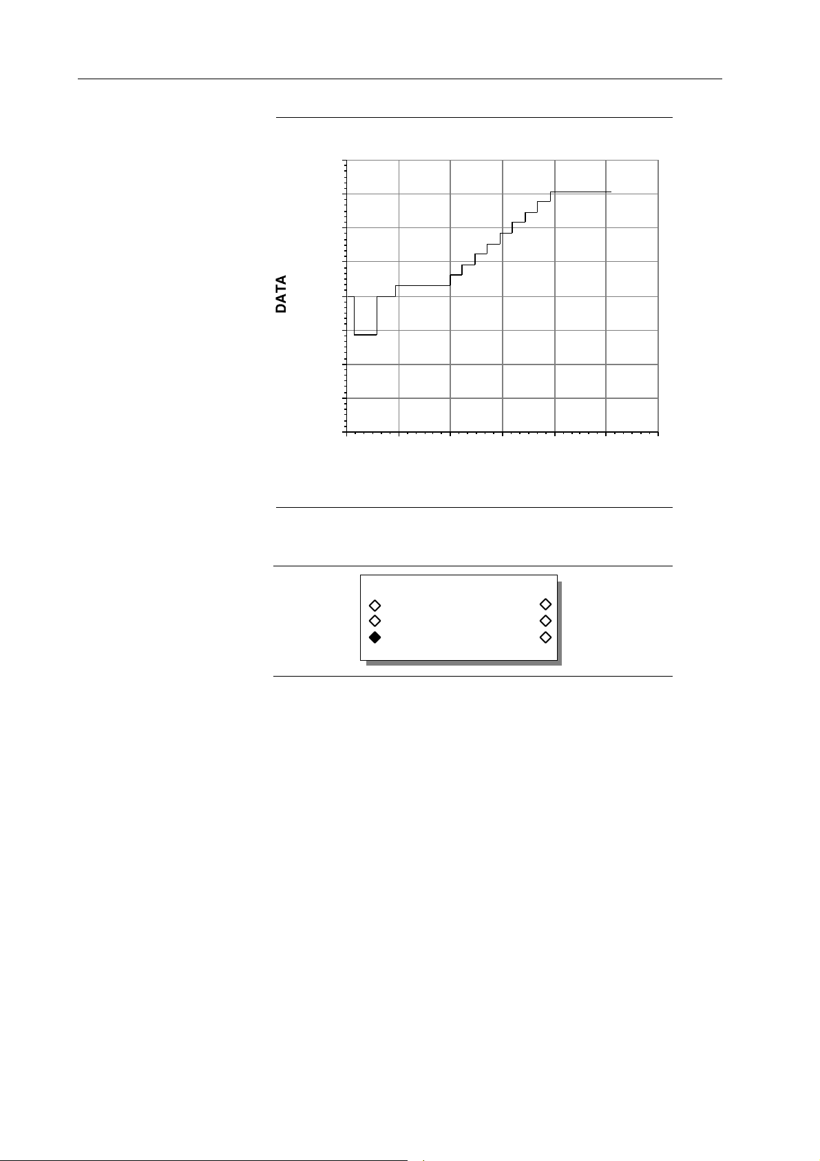
This example creates waveform that simulates a nine-step gray scale video signal.
Paragraph 5.5.2, example 2 contains the remote SCPI programming equivalent of this
example. You will use this waveform with example 3.
If you want to view the signal on an oscilloscope, connect the Model 395 to the scope
as described in paragraph 3.5. First setup the Model 395 as described in example 1, steps
1, 2, and 3.
Step 1 Naming and Sizing the Waveform
The first step in creating the waveform is to name it and define its size. Start by pressing
the CREATE key under WAVEFORM EDIT which displays the Create New Waveform
screen.
WAVEFORM EDIT
CREATE
CREATE NEW WAVEFORM
F3
(avail mem: 61972)
create blank …
create from copy …
Press F3 to select “create blank … .” Note: the Model 395 uses ellipsis, …, to tell you
there are additional screens. If you pressed F4, “create from copy … ,” you could copy
an existing waveform and modify the copy.
Give the waveform a name using the knob and right cursor key. Rotate the knob until
the first character displays “g” and press the right cursor. Again rotate the knob until the
second character displays “r” and press the right cursor. Continue until you have entered
“a” and “y.” Both letters and numbers can be used in names, but the first character must
always be a letter.
CREATE: "gray_____"
size: 1024
(max: 61972)
cancel create
Size defines the number of points in the waveform. Select “size” by pressing the F2 key.
Use the keypad to enter 2540 points.
2 5 4 0
Introduction To The Model 395 3-11
Page 38
CREATE: "gray_____"
size: 2540
(max: 61972)
cancel create
F8
Step 2. Creating the Waveform
Press F8 “create” to accept the name and size and advance to the Modify screen.
MODIFY: sync1
resize … rename …
F4
From the Modify screen press F4 “edit waveform” which displays the editing screen.
Then from the edit screen, press F3 to select “line draw.”
F3
delete … limits …
edit waveform …
EDIT FUNCTIONS
point edit …
line draw … exit
(use knob to scroll)
Line draw consists of defining points and drawing lines between the points (address and
data value). The range of addresses in this example are 0 to 2539, and the range of data
values for each address is -2048 to +2047.
To enter the first point, press F2 “fm … adrs.”
LINE (adrs ,data)
fm: (000000 ,+0000)
to: (002539 ,+0000)
exit draw line
Then using the keypad enter 0. Next press F6 “fm … data.”
LINE (adrs ,data)
fm: (000000 ,+0000)
to: (002539 ,+0000)
exit draw line
3-12 Introduction To The Model 395
Page 39

Then using the keypad, enter 0000. Next press F3 “to … adrs.”
LINE (adrs ,data)
fm: (000000 ,+0000)
to: (002539 ,+0000)
exit draw line
Next use the keypad to enter 59. Then press F7 “to … data.”
LINE (adrs ,data)
fm: (000000 ,+0000)
to: (000059 ,+0000)
exit draw line
Use the keypad to enter 2048. Finally, press F8 “line draw” to draw the line.
LINE (adrs ,data)
fm: (000000 ,+0000)
to: (000059 ,+2048)
exit draw line
Use the following table to enter the rest of the waveform data. Figure 3-11 illustrates the
waveform plotted by the data.
From Adrs From Data To Adrs To Data Press
60 -577 280 -577 “draw line”
281 +0000 461 +0000 “draw line”
462 +154 981 +154 “draw line”
982 +308 1102 +308 “draw line”
1103 +462 1223 +462 “draw line”
1224 +616 1344 +616 “draw line”
1345 +770 1465 +770 “draw line”
1466 +924 1586 +924 “draw line”
1587 +1078 1707 +1078 “draw line”
1708 +1232 1827 +1232 “draw line”
1828 +1386 1949 +1386 “draw line”
1950 +1540 2539 +1540 “draw line”
Introduction To The Model 395 3-13
Page 40
ADDRESS
+2047
+1536
+1024
+512
+0000
DATA
-512
-1024
-1536
-2048
Figure 3-11. Waveform: “gray”
Press F4 “exit” when finished.
300025002000150010005000
ADDRESS
LINE (adrs ,data)
fm: (001950 ,+1540)
to: (002539 ,+1540)
exit draw line
Example 3 Generating the Arb Waveform
Now that the Arbitrary waveform “gray” has been created, you can output it like a
standard waveform. Paragraph 5.5.2, example 3 contains the remote SCPI programming
equivalent of this example. First setup the Model 395 as described in example 1, steps
1, 2, and 3.
Step 1 Selecting Arb Waveform “gray”
Press the ARBITRARY key to display the Arbitrary Waveforms screen. The display
lists all Arbitrary waveforms stored in memory.
3-14 Introduction To The Model 395
Page 41

ARBITRARY
ARBITRARY WAVEFORMS
gray 002540
wv1 001024
(use knob to scroll)
Find “gray” and press the softkey next to it; for example, F2.
Step 2 Selecting Continuous Mode
Select the unit’s operating mode by pressing the MODE key which displays the Mode
screen.
F1
continuous
sweep
gated
trig'd , cnt: 0000001
Press F1 to select the continuous mode.
Step 3 Setting Waveform Period
To set the waveform period, press the FREQUENCY key to bring up the Arbitrary
Frequency screen. Press F7, “waveform,” and then press F8 “period.” Waveform
frequency, sample frequency, and sample period can also be displayed.
FREQUENCY
ARBITRARY FREQUENCY
50.80 µSec
sample waveform
freq peroid
Enter the waveform period by pressing:
6 4 +/-
EXP
F7
F8
ENTER
6
Introduction To The Model 395 3-15
Page 42

Step 4 Setting the Amplitude
Set the amplitude to 5.4 Vp-p by first pressing the AMPLITUDE key. From the
Amplitude screen, press F3, “Vpp”, to display the amplitude units in Volts peak-to-peak.
AMPLITUDE
AMPLITUDE
F3
Enter the amplitude level by pressing:
5
+2.00 Vpp
Vpp Vp
Vrms dBm
ENTER
•
4
Step 5 Offsetting the Waveform
Offset the waveform’s baseline -0.5 Vdc by pressing the OFFSET key.
OFFSET
OFFSET
+0.00 Vdc
From the Offset screen press:
ENTER
+/-
•
5
3-16 Introduction To The Model 395
Page 43

The scope now displays the Gray Scale waveform similar to the one shown below:
DATA
Example 4. Creating an Arb Waveform Using Waveform Insert
The waveform, sync1, is a 120 point square wave that illustrates wave insert editing.
Paragraph 5.5.2, example 4 contains the remote SCPI programming equivalent of
this example. The waveform, sync1, will be used with example 6, creating a
sequence.
First set up the Model 395 as described in example 1, steps 1, 2, and 3.
Step 1. Naming and Sizing the Waveform
The first step in creating the waveform is to name it and to define its size. Start by
pressing the CREATE key under WAVEFORM EDIT which displays the Create
New Waveform screen.
WAVEFORM EDIT
CREATE
CREATE NEW WAVEFORM
F3
(avail mem: 61972)
create blank …
create from copy …
Press F3 to select “create blank … .”
Using the knob and right cursor key name the waveform. Rotate the knob until the
first character displays “s” and press the right cursor. Repeat the process until you
spell sync1. Both letters and numbers can be used when creating a name, but the
first character must always be a letter.
CREATE: "sync1_____"
size: 1024
(max: 61972)
cancel create
Introduction To The Model 395 3-17
Page 44

Size defines the number of points in the waveform. Select “size” by pressing the F2 key.
Use the keypad to enter 120 points:
ENTER
1 2 0
Press F8, “create,” to accept the name and the size and advance to the Modify screen.
CREATE: "sync1_____"
size: 120
(max: 61972)
cancel create
F8
MODIFY: sync1
resize … rename …
F4
delete … limits …
edit waveform …
From the Modify screen press F4 “edit waveform” which displays the Edit screen.
EDIT FUNCTIONS
point edit …
line draw … exit
(use knob to scroll)
Rotate the knob until Wave Insert appears. Then press the soft key to select Wave Insert
….”
F1
square --> sync1
________ start 000000
________stop 000119
F8
exit insert
Press F1 until “square“ appears. Then press F8 to insert the square wave between
address 000000 and address 000119. Select “exit,” F4 to return to the waveform edit
screen.
Step 2 Adding Position Markers
You can add position markers to Arbitrary waveform that will consist of a high pulse for
the first ten points of the waveform in this example. This pulse will synchronize the
scope to the waveform sequence (example 7). To enable the position marker, select sync
source: “pos’n mrks” via the SYNC OUT key.
3-18 Introduction To The Model 395
Page 45

From the Waveform Edit screen, scroll to and select “pos’n mrkrs.”
F2 F6
POSITION MARKER EDIT
addrs: 000000 <0>
patterns …
clear all … done
To create the pulse, press F6 to change <0> to <1>. Press F2 to advance to 000001, and
press F6 to change to <1>. Continue on to address 000009 setting all points to <1>. Press
F8 “done” when finished.
Example 5. Creating an Arbitrary Waveform Using Point Edit
The waveform, sync2, is a 40 point arbitrary waveform which demonstrates point
editing. Paragraph 5.5.2, example 5 contains the remote SCPI programming equivalent
of this example. The waveform, sync2, will be used in example 6, creating a sequence.
First setup the Model 395 as described in example 1, steps 1, 2, and 3.
Step 1. Naming and Sizing the Waveform
The first step is to give the waveform a name and to define its size (number of points).
Start by pressing the CREATE key under WAVEFORM EDIT which displays the
Create New Waveform screen.
WAVEFORM EDIT
CREATE
CREATE NEW WAVEFORM
F3
(avail mem: 61972)
create blank …
create from copy …
Press F3 to select “create blank … .”
Using the knob and right cursor key name the waveform. Rotate the knob until the first
character displays “s” and press the right cursor. Repeat the process until you spell
sync2.
Introduction To The Model 395 3-19
Page 46

CREATE: "sync2_____"
size: 1024
(max: 61972)
cancel create
Size defines the number of points in the waveform. Select “size” by pressing the F2 key.
Use the keypad to enter 40 points.
ENTER
4
CREATE: "sync2_____"
size: 40
(max: 61972)
cancel create
Press F8 “create” to accept the name and size and advance to the Modify screen.
0
F8
MODIFY: sync2
resize … rename …
F4
From the Modify screen press F4 “edit waveform” which displays the editing screen.
EDIT FUNCTIONS
Press F2 to change to the point edit screen.
To create a waveform using point edit, select the address and enter the data value for that
address. Point editing requires you to enter one point at a time. However, if you select
“next point” the unit increments to the next address.
delete … limits …
edit waveform …
point edit …
line draw … exit
(use knob to scroll)
POINT EDIT
(adrs ,data)
(000000,+0000)
exit next point
3-20 Introduction To The Model 395
Page 47

With the address at 000000, press F7 and enter -2048 from the keypad. Press F8 “next
point” to advance to address 000001. Continue entering points as listed below:
Address Press F7, enter data Press F8
000000 -2048 “next point”
000001 -48 “next point”
000002 -48 “next point”
000003 1952 “next point”
000003 to 000036 use data = 1952
000036 4000 “next point”
000037 -48 “next point”
000038 -2048 “next point”
000039 -2048
Press F4 “exit.”
+2047
+1536
+1024
+512
Data
+0000
-512
-1024
-1536
-2048
4035302520151050
Address
Introduction To The Model 395 3-21
Page 48

3.8 THE MODEL 395 AS A WAVEFORM SEQUENCE GENERATOR
Example 6 Creating a Waveform Sequence
This sequence combines the waveforms you created in examples 4 and 5 (sync1 and
sync2) to form a simulated vertical sync signal for video applications. Paragraph 5.5.3,
example 6 contains the remote SCPI programming equivalent of this example.
First setup the Model 395 as described in example 1, steps 1, 2, and 3.
Step 1. Accessing Sequence Setup
To begin setting up the sequence, press the SEQUENCE key to display the Sequence Edit
screen.
F2
Press F2, “sequence setup … .”
SEQUENCE EDIT
sequence setup …
advance trig setup …
stop start
Step 2 . Selecting the First Waveform (Segment)
seg:1 delete
wfm: —————— limit
advance: count
cnt:1 done
Press F1, “seg:” until “seg:1” is displayed.
Press F2, “wfm” and use the knob to located “sync1.” If sync1 is unlisted, you should
create the waveform: example 4.
F1
F2
seg:1 delete
wfm: sync1 limit
advance: count
cnt:1 done
For this example leave the segment set to the default advance: count and count: 1
conditions.
Step 3 Selecting the Second Waveform (Segment)
Press F1, “seg:” until “seg:2” is displayed.
Press F2, “wfm:” and use the knob to locate “sync2.” If sync2 is unlisted, you should
create the waveform: example 5.
3-22 Introduction To The Model 395
Page 49
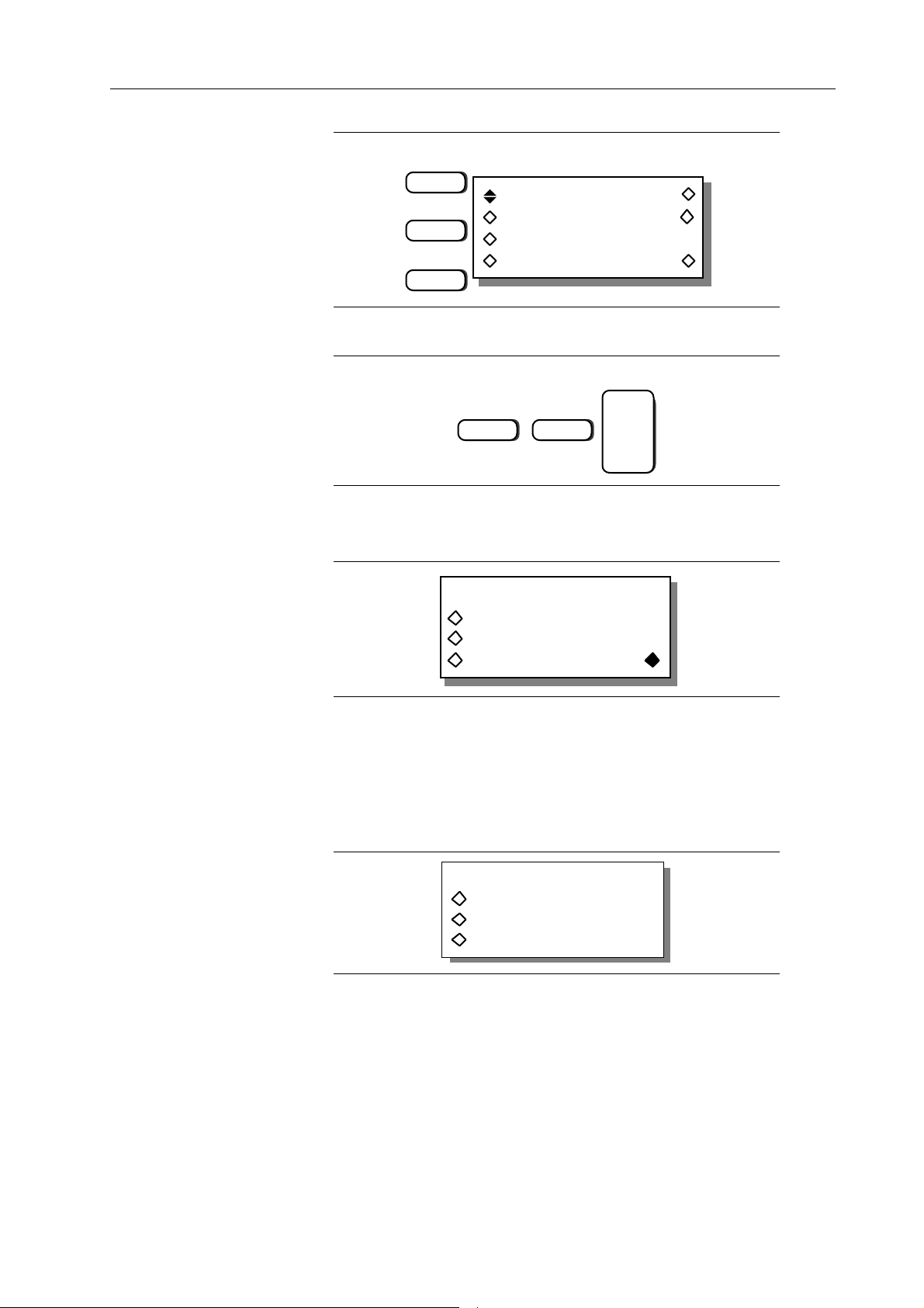
F1
seg:2 delete
F2
F4
For this example leave advance set to count. But press F4 “cnt,” and set the count to 12
by pressing:
wfm: sync2 limit
advance: count
cnt:12 done
ENTER
1
The sequence is now setup.
Press F8, “done” to return to the Sequence Edit screen. Press F8, “start” to run the
sequence.
SEQUENCE EDIT
sequence setup …
advance trig setup …
stop start
2
Step 4. Synchronizing The Sequence
In example 4 you defined position markers for the “sync1” waveform. To synchronize
the scope to the sequence, press the SYNC OUT key to display the Sync Output screen,
Then press F2 “output” until “on” appears to enable the Sync Out. Next, press F4 “src:”
until “pos’n mark” appears to select the position marker as the sync source.
SYNC OUTPUT SETUP
output: on
mode: auto
src: waveform sync
Introduction To The Model 395 3-23
Page 50
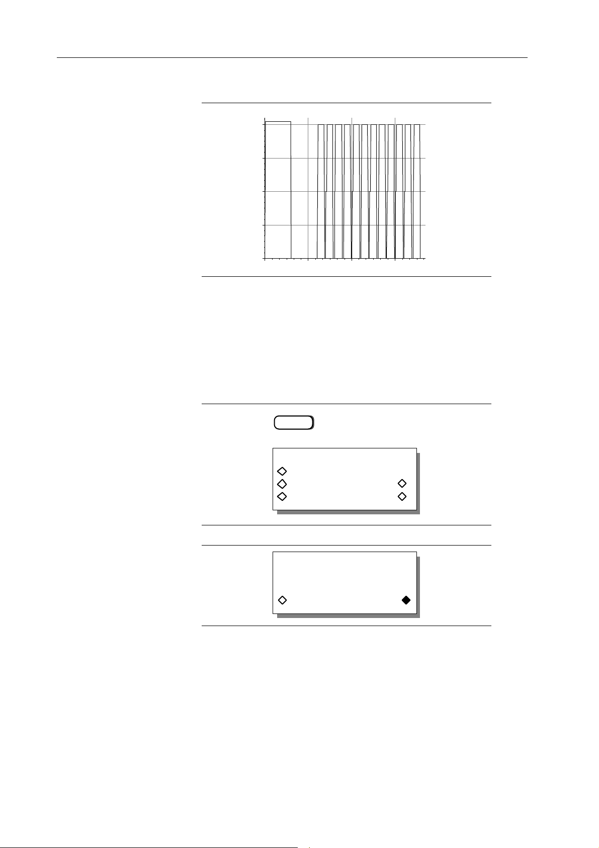
The scope displays:
Data
3.9 STORING AND RECALLING SETUPS
Example 7. Storing and Recalling an Instrument Setup
This example stores the sequence created in example 6. One reason for doing this is
because it is the only way the Model 395 will store a sequence. Paragraph 5.5.4, example
7 contains the remote SCPI programming equivalent of this example.
Step 1 Storing The Sequence
Press the SETUPS key to display the Stored Setups screen.
SETUPS
STORED SETUPS
setup name: —————
save … recall
save as … delete …
To store a new setup, press F4 “save as …. .”
Use knob to enter a
new setup name
"setup1 _ _"
cancel save
For this example, use the default name “setup1.” If the setup is named “startup” a setup
configuration can be used as the power on default.
Press F8, “save” to store the setup.
3-24 Introduction To The Model 395
Page 51
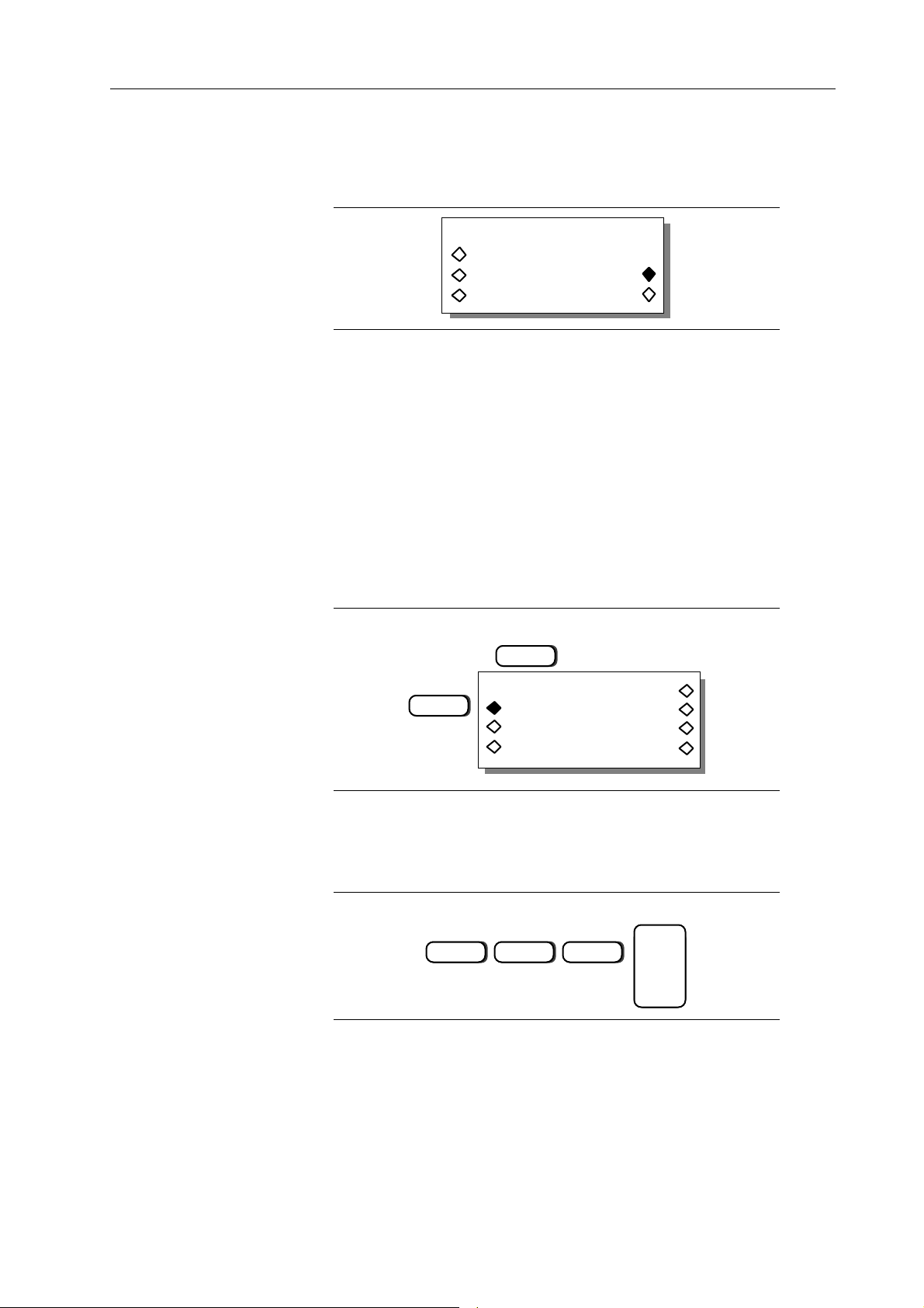
Step 2. Recalling The Sequence
First turn off the POWER switch, and then turn the POWER back on. Recall the stored
setup “setup1” by pressing the SETUPS key.
STORED SETUPS
setup name: setup1
save … recall
save as … delete …
From the Stored Setups screen, press F2, “setup name:” until “setup1” appears. Then
press F7, “recall” to recall the sequence.
3.10 THE MODEL 395 AS A SWEEP GENERATOR
Example 8. Setting up the Sweep Generator
This example creates a triggered sweep waveform that uses the Model 395’s internal
trigger source. The generator sweeps between 200 kHz and 400 kHz at a 5 second sweep
rate. The trigger source is programmed to 15 seconds. Paragraph 5.5.5, example 8,
contains the remote SCPI programming equivalent of this example. First setup the
Model 395 as described in example 1, steps 1, 2, and 3.
Step 1 Accessing the Sweep Setup Screen
Begin by pressing the SWEEP OUT key to switch to the Sweep Setup screen.
SWEEP OUT
F2
SWEEP SETUP on
range … type…
time … spacing …
manual … marker …
Step 2 Setting Sweep Start and Stop Frequencies
Press F2, “range,” on the Sweep Setup screen to set the start and stop frequencies. From
the Sweep Range screen, set the Start frequency by pressing F2, “start,” then using the
keypad enter:
ENTER
2
EXP
5
Introduction To The Model 395 3-25
Page 52
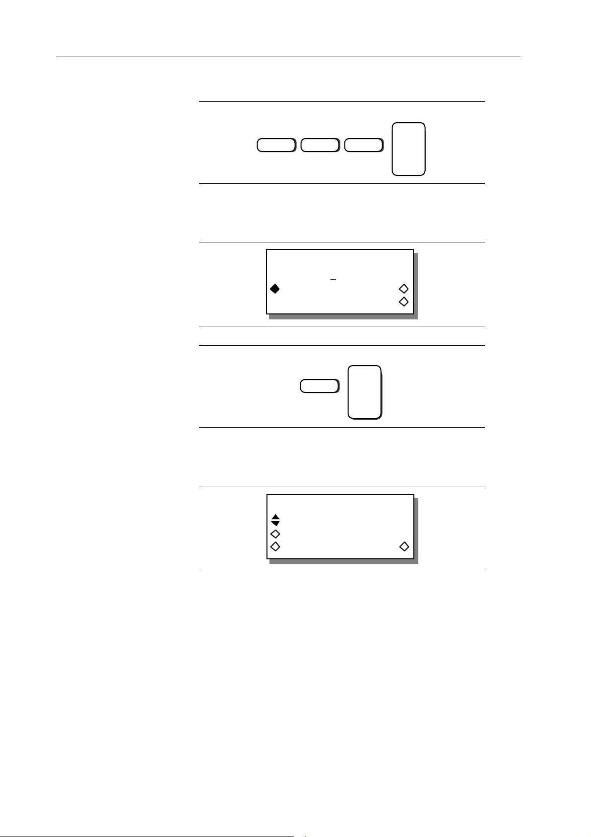
Press F3, “stop,” and use the keypad to enter:
ENTER
4
Press F8 “done” to return to the Sweep Setup screen.
EXP
5
Step 3 Setting the Sweep Time
Press F3 “time” on the Sweep Setup screen to display the Sweep Time screen.
SWEEP TIME
time: 1.000 sec
time freq
(steps=2000) done
Use the keypad to enter the sweep time:
ENTER
5
Press F8, “done,” to return to the Sweep Setup screen.
Step 4 Selecting the Sweep Type
From the Sweep Setup screen, press F6 “type” to select the Sweep Type screen.
SWEEP TYPE
trig, 2 direction
trig count: 0000001
dir: up done
Press F2 and use the knob to locate: “trig, 2 direction .” For this example, leave the
sweep direction set to “up” and “trigger count” set to 1. Press F8, “done,” to return to
the Sweep Setup screen. Leave the sweep spacing set to linear in this example.
Step 5 Selecting the Waveform to Sweep
The Model 395 uses the last selected waveform. For this example select the sine
waveform by pressing the Waveform Select’s STANDARD key. Then select the sine
waveform. For help on how to select a waveform, refer to example 1, step 5.
3-26 Introduction To The Model 395
Page 53

Step 6 Enabling Sweep
You can select the Sweep mode from either the Sweep Setup screen or the Mode screen.
From the Sweep Setup screen, press F5 “on” to switch to the sweep mode. From the
Mode screen, press F2 “sweep” to enable the sweep mode. Selecting either one also
enables the Sweep Out connector which produces a ramp proportional to the sweep time.
Step 7 Setting Up Trigger Source
Set up the trigger source and trigger rate via the Trigger screen, enabled by pressing the
TRIG IN key.
source : internal
slope : positive
level : +0.00 V
period : 1.0000 ms
Select the internal trigger source by pressing F1 “source” until “internal” appears. Set
the trigger period to 15 seconds by pressing F4 to select “period” then enter:
ENTER
1 5
The Model 395 is now generating a swept sine wave.
3.11 THE MODEL 395 AS A TRIGGER GENERATOR
Example 9 Setting up the Triggered Generator
In this example you will set up the Model 395 to generate a triggered Sin (x)/x waveform
for a count of five waveforms. This example uses the Model 395’s MAN TRIG key to
trigger the waveforms. Paragraph 5.5.6, example 9 contains the remote SCPI programming
equivalent of this example. First setup the Model 395 as described in example 1, steps
1, and 2.
Introduction To The Model 395 3-27
Page 54
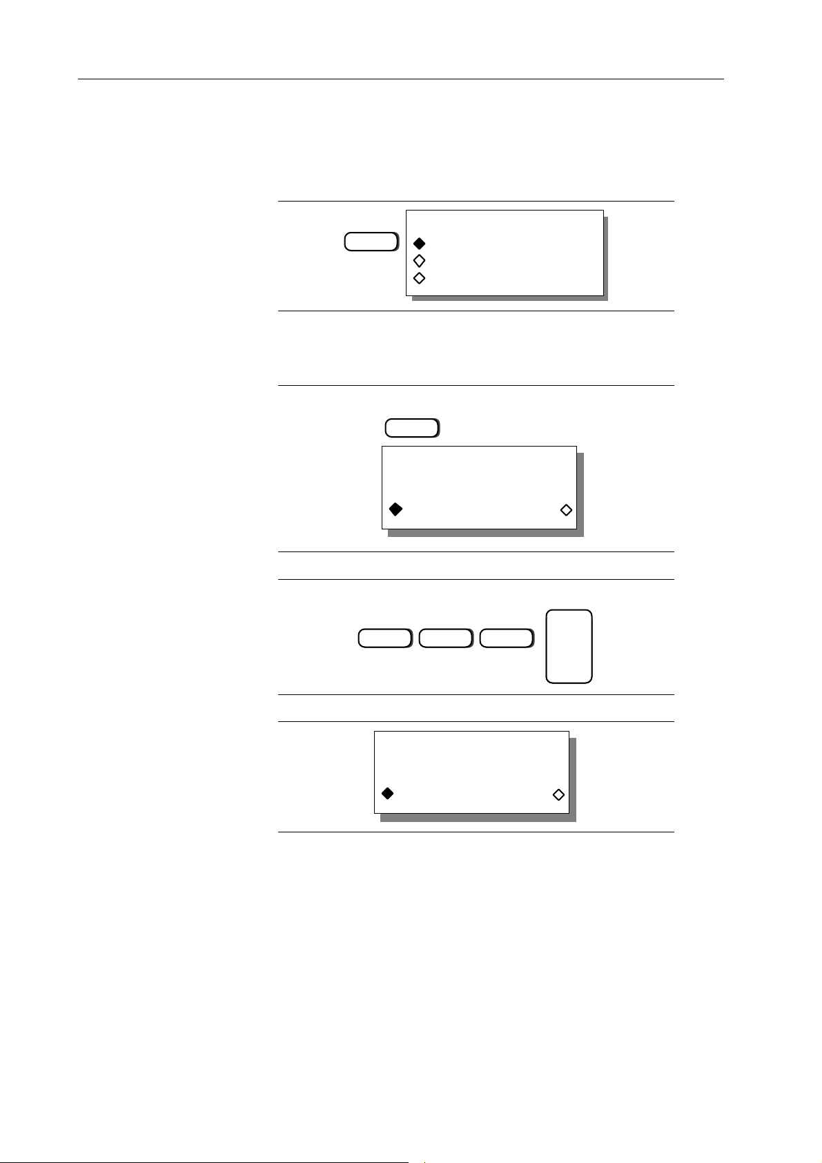
Step 1. Selecting the Sin (x)/x Waveform
Select a waveform by pressing the STANDARD key under Waveform Select to display
the Waveform screen. Rotate the knob until “sin(x)/x” appears on the screen. Press the
softkey to the left of “sin(x)/x” to select the waveform.
STANDARD WAVEFORMS
sin(x)/x
+hvrsine
-hvrsine
Step 2. Setting the Frequency to 300 Hz
Program the frequency of the waveform by pressing the FREQUENCY key to display
the Standard Frequency Screen:
FREQUENCY
STANDARD FREQUENCY
1.000000000 kHz
freq period
To change the frequency, press these keys:
3
The screen reads:
STANDARD FREQUENCY
0
300.000000 Hz
freq period
ENTER
0
3-28 Introduction To The Model 395
Page 55

Step 3. Selecting the Triggered Count Mode
To set the triggered count operating mode, press the MODE key to display the Mode
screen:
MODE
continuous
sweep
gated
trig'd, cnt: 0000001
First select the triggered mode by pressing F4 “trig’d.”
continuous
sweep
F4
Next enter the trigger count using the keypad to enter:
gated
trig'd, cnt: 0000001
ENTER
5
Step 4. Setting Up the Trigger Source
Set up the trigger source via the Trigger screen, enabled by pressing the TRIG IN key.
TRIG IN
source: internal
slope : positive
level : +0.00 V
period: 5.0000 ms
Introduction To The Model 395 3-29
Page 56
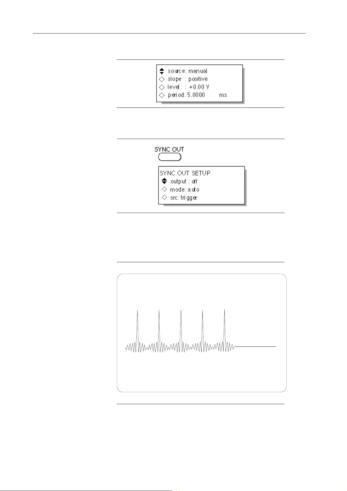
Select the external trigger source by pressing F1 “source:” until “manual” appears:
Step 5. Synchronizing the Scope to the Model 395
To synchronize the scope signal with the Model 395, press the SYNC OUT key to
display the Sync Output Setup screen:
Enable the Sync Out signal by pressing F2 until “output: on” appears. The Sync Out
indicator lights. Press F4 “src:” until “trigger” appears. Note: when the “mode” is set
to auto, the Model 395 automatically selects trigger source.
If you connect the Model 395 to an oscilloscope, as described in paragraph 3.5, you will
see a burst of five sin(x)/x waveforms each time the Model 395’s MAN TRIG key is
pressed. Be sure to setup the scope’s sync correctly in order to see the burst.
3-30 Introduction To The Model 395
Page 57
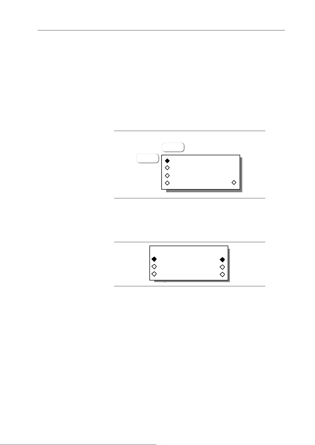
3.12 THE MODEL 395 AS A PULSE GENERATOR
Example 10 Setting up the Pulse Waveform
This example sets up the Model 395 to produce a continuous 10 µs, 1 µs wide pulse with
fixed rise/fall edges and 2 µs delayed relative to the Sync Out signal. Paragraph 5.5.7,
example 10 contains the remote SCPI programming equivalent of this example.
First setup the Model 395 as described in example 1, steps 1, 2, and 3. Also, connect
the scope and Model 395 as described in paragraph 3.5.
Step 1 Selecting Continuous Mode
To set the operating mode to continuous, press the MODE key to display the Mode
screen:
MODE
F1
continuous
sweep
gated
trig'd, cnt: 0000001
Press F1, “continuous,” to select this mode. Continuous is the default mode.
Step 2. Selecting Pulse Setup
Set up the pulse waveform by pressing the STANDARD key under Waveform Select
to display the Waveform screen. Rotate the knob to display “pulse setup …” on the
screen.
STANDARD WAVEFORMS
pulse setup …
pulse train setup …
digtl noise setup …
Selecting “pulse setup” allows you to define the pulse parameters. By selecting “pulse”
you enable the pulse waveform using its current parameters.
For this example, press the softkey to the left of “pulse” to allow you to see the pulse
as you create it.
Introduction To The Model 395 3-31
Page 58

Step 3 Setting Up the Pulse Parameters
From the Standard Waveform screen, press the softkey to the right of “pulse setup …”
which displays the Pulse Period screen.
Enter pulse period:
300.0 µs
exit next
Step 4 Programming Pulse Period
From the pulse period screen set the period to 10 µs by pressing:
ENTER
+/-1 EXP
5
Step 5 Defining the Leading and Trailing Edges
Press F8, “next,” to advance to the Lead/Trail Edge screen. For this example, press F3,
“fixed,” to use the fixed rising and falling edges. If “variable” were selected, additional
screens will lead you through the setting of the edges.
Are lead/trail edges
fixed or variable?
fixed variable
exit next
Step 6 Selecting Pulse Width
Press F8, “next,” to advance to the Pulse Width screen:
Enter width:
program: 5.000 µs
exit next
From the Pulse Width screen, set the pulse width to 1 µs by pressing:
ENTER
+/-1 EXP
6
3-32 Introduction To The Model 395
Page 59

Step 7 Programming Pulse Delay
Press F8, “next,” to advance to the Pulse Delay screen.
Enter delay:
program: + 0.000 s
(actual: +0.000 s)
exit next
From this screen, set the 2 µs pulse delay relative to the Sync Out signal. Press these
keys:
ENTER
+/-2 EXP
Press F4, “exit,” to return to the Standard Waveform screen.
6
Step 8 Setting Upper Pulse Levels
When running a pulse waveform, you can set the upper level of the pulse by pressing the
Amplitude key.
AMPLITUDE
PULSE UPPER LEVEL:
To set pulse level to +2.5 V press:
2
+1.000 V
•
5
ENTER
Introduction To The Model 395 3-33
Page 60

Step 9 Setting Lower Pulse Levels
When running a pulse waveform, you can set the lower level of the pulse by pressing the
Offset key.
OFFSET
PULSE LOWER LEVEL:
-1.000 V
To set pulse level to 0.0 V, press:
ENTER
0
The scope displays the following waveform:
Example 11 Setting up the Pulse Train Waveform
This example creates a pulse train of three pulses, each with their own widths, levels, and
rise/fall times. Paragraph 5.5.7, example 11 contains the remote SCPI programming
equivalent of this example. First setup the Model 395 as described in example 1, steps
1, 2, and 3.
3-34 Introduction To The Model 395
Page 61

Step 1. Selecting Continuous Mode
To set the operating mode to continuous, press the MODE key to display the Mode
screen:
MODE
F1
continuous
sweep
gated
trig'd, cnt: 0000001
Press F1, “continuous,” to select this mode. Continuous is the default mode.
Step 2. Selecting Pulse Train
Set up the pulse-train by pressing the STANDARD key under Waveform Select which
displays the Standard Waveform screen. Rotate the knob to display “pulse-train setup
…” on the screen.
Note
If “pulse-train” was selected before “pulse-train setup…,”leading
edge, trailing edge, and delay screens will also display an actual value.
STANDARD WAVEFORMS
pulse setup …
pulse-train setup …
digtl noise setup …
Step 3 Define Number of Pulses
Selecting “setup …” displays the “Enter number of pulses …” screen. A pulse train can
contain from 1 to 10 pulses.
Enter no. of pulses
in train (1 - 10):
2
exit next
Introduction To The Model 395 3-35
Page 62

For this example, program three pulses by pressing:
ENTER
3
Press F8, “next,” to advance to the Pulse Train period screen.
Step 4. Programming Pulse Train Period
Pulse train period defines the repetition rate for the entire pulse train.
Enter period of the
pulse train:
300.0 µs
exit next
For this example, program the pulse train period to 500 ms by pressing:
ENTER
+/-5 EXP
1
Press F8, “next,” to advance to the Edge screen.
Step 5 Selecting Fixed or Variable Edges
Pulse train allows you to use fixed leading / trailing edges or set variable leading and
trailing edges. This example uses variable edges.
Are lead / trail edges
fixed or variable?
fixed variable
exit next
Press F7, “variable,” and then press F8, “next,” to advance to the Baseline screen.
Step 6 Setting Baseline
Baseline lets you set a reference voltage level for the entire pulse train.
Enter baseline
voltage:
+0.000 V
exit next
3-36 Introduction To The Model 395
Page 63

Set the baseline voltage to -4 V by pressing:
ENTER
+/-
Press F8, “next,” to advance to the Pulse Level screen.
4
Step 7 Setting the Level of Pulse 1
Pulse train allows you to define the upper level of each pulse in the train.
Pulse 1 level
+2.000 V
exit next
First, select Pulse 1 by pressing F1 until “Pulse 1 Level” appears. Next, press F3, and
set the level of pulse 1 to +4 V by pressing:
ENTER
4
Step 8 Setting the Leading Edge of Pulse 1
Press F8, “next,” to advance to the Pulse 1 Leading Edge screen.
Pulse 1 leading edge:
program: 100. ns
exit next
Set the leading edge to 32 ms by pressing:
3
2 EXP
+/-
3
ENTER
Introduction To The Model 395 3-37
Page 64

Step 9 Setting the Trailing Edge of Pulse 1
Press F8, “next,” to advance to the Pulse 1 Trailing Edge screen.
Pulse 1 trailing edge:
program: 50. ns
exit next
Set the trailing edge of pulse number 1 to 64 ms by pressing:
6
4 EXP
+/-
3
Step 10 Programming Pulse Width of Pulse 1
Press F8, “next,” to advance to the Pulse 1 Pulse Width screen.
Pulse 1 width:
program: 1.000 µs
ENTER
exit next
Set the pulse width to 120 ms by pressing:
ENTER
1 •
2 EXP
+/-
1
Step 11 Programming the Delay of Pulse 1
Press F8, “next,” to advance to the Pulse Delay screen. Delay defines the pulse’s actual
position in the pulse train relative to the Sync Out signal.
Pulse 1 delay:
program: +0.0000 s
exit next
3-38 Introduction To The Model 395
Page 65
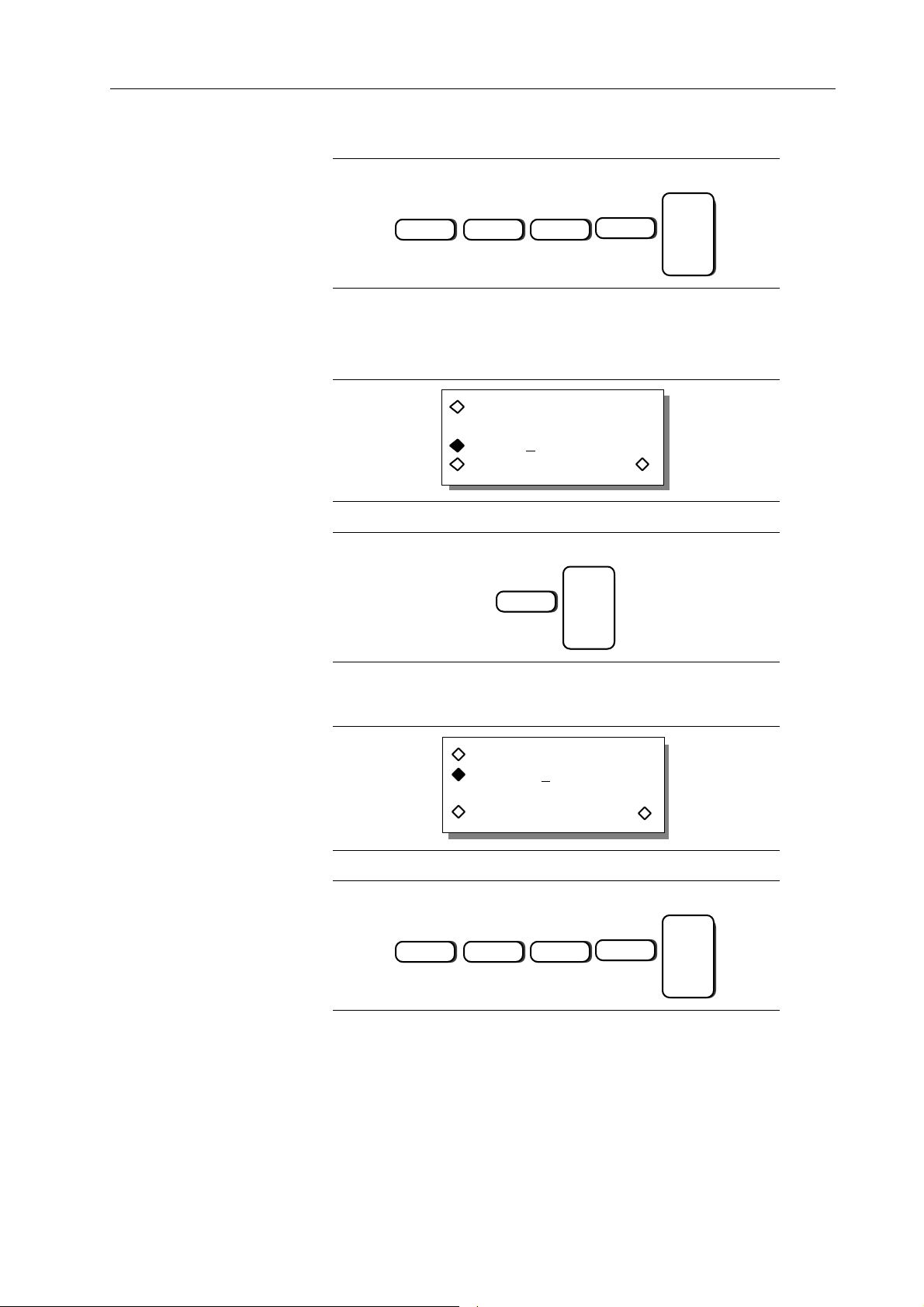
For this example, program the delay to 40 ms by pressing:
ENTER
4 EXP
Press F8, “next,” to display the Pulse Level screen.
+/-
2
Step 12 Selecting Pulse 2 and Setting the Level
From the Pulse Level screen, press F1 until “Pulse 2” appears.
Pulse 2 level:
-4.500 V
exit next
Press F3, and use the numeric keypad to set the upper level to +2 V by pressing:
ENTER
2
Step 13 Defining the Leading Edge of Pulse 2
Press F8, “next,” to display the Leading Edge screen.
Pulse 2 leading edge:
program: 100. ns
exit next
Set the leading edge to 8 ms by pressing:
ENTER
8 EXP
+/-
3
Introduction To The Model 395 3-39
Page 66

Step 14 Programming the Trailing Edge of Pulse 2
Press F8, “next,” to display the Trailing Edge screen.
Pulse 2 trailing edge:
program: 50. ns
exit next
Set the trailing edge to 8 ms by pressing:
ENTER
8 EXP
+/-
3
Step 15 Changing Pulse Width of Pulse 2
Press F8, “next,” to display the Pulse Width screen.
Pulse 2 width:
program: 1.000 µs
exit next
Set the pulse width of pulse number 2 to 60 ms by pressing:
ENTER
6 EXP
+/-
2
Step 16 Setting Pulse Delay of Pulse 2
Press F8, “next,” to advance to the Pulse Delay screen. Delay defines the pulse’s actual
position in the pulse train relative to the Sync Out signal.
Pulse 2 delay:
program: +0.0000 s
exit next
3-40 Introduction To The Model 395
Page 67
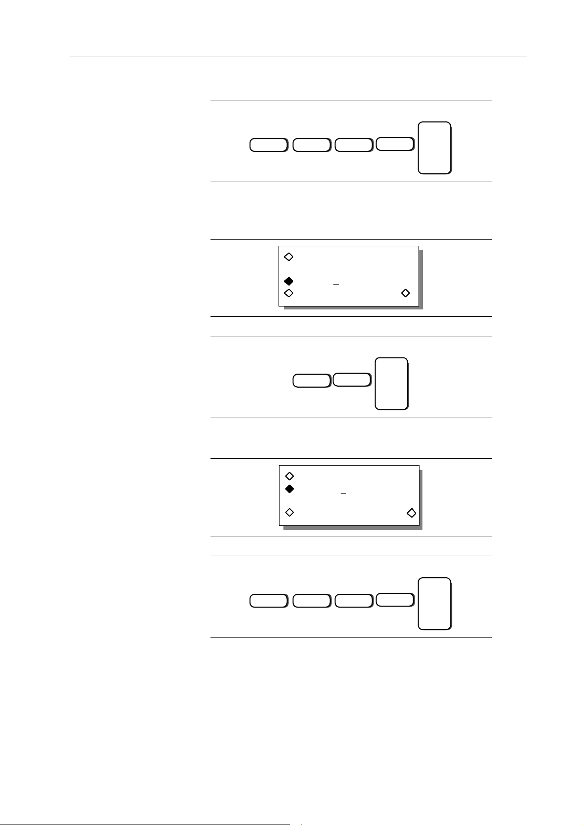
For this example, program the delay to 300 ms by pressing:
ENTER
3 EXP
Press F8, “next,” to display the Pulse Level screen.
+/-
1
Step 17 Selecting Pulse 3 and Setting the Level
From the Pulse Level screen, press F1 until “Pulse 3” appears.
Pulse 3 level:
+5.000 V
exit next
Press F3, and use the numeric keypad to set the upper level to -2 V by pressing:
ENTER
+/-
2
Step 18 Defining the Leading Edge of Pulse 3
Press F8, “next,” to display the Leading Edge screen.
Pulse 3 leading edge:
program: 100. ns
exit next
Set the leading edge to 8 ms by pressing:
ENTER
8 EXP
+/-
3
Introduction To The Model 395 3-41
Page 68
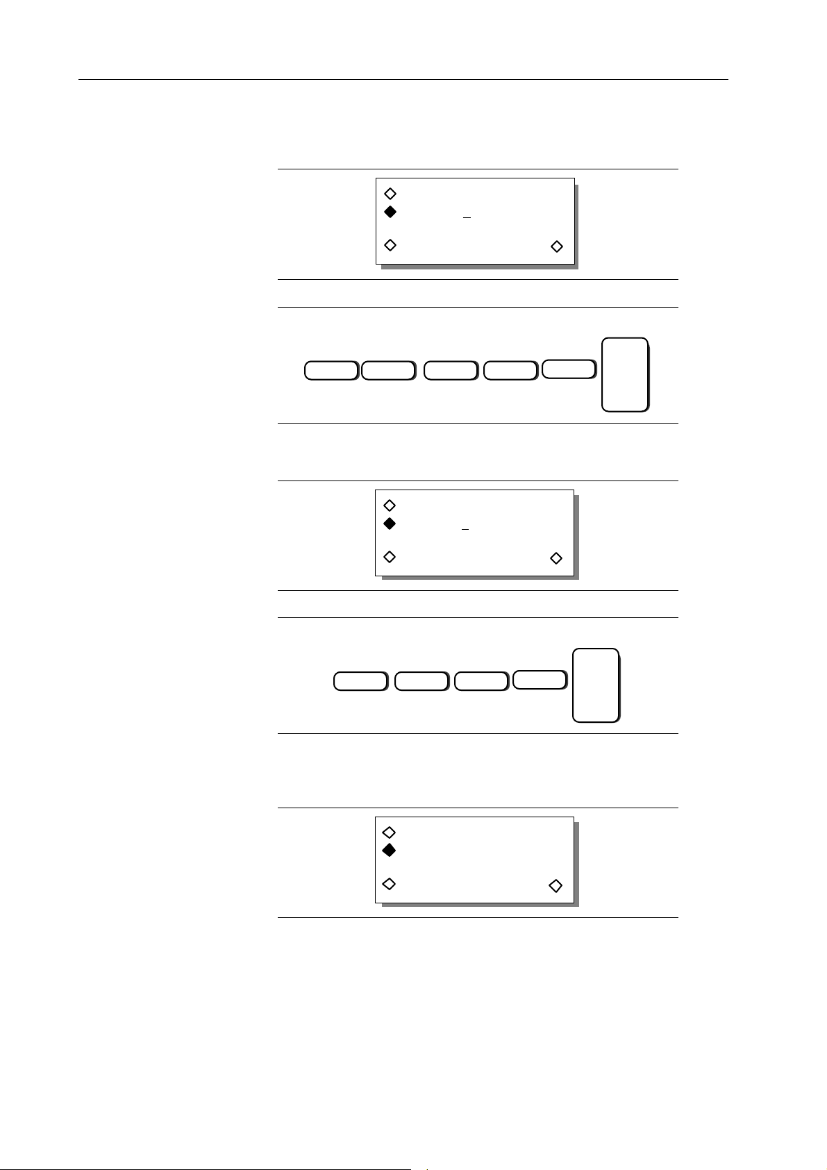
Step 19 Programming the Trailing Edge of Pulse 3
Press F8, “next,” to display the Trailing Edge screen.
Pulse 3 trailing edge:
program: 50. ns
exit next
Set the trailing edge to 32 ms by pressing:
ENTER
3
2 EXP
+/-
3
Step 20 Changing Pulse Width of Pulse 3
Press F8, “next,” to display the Pulse Width screen.
Pulse 3 width:
program: 1.000 µs
exit next
Set the pulse width of pulse 3 to 50 ms by pressing:
ENTER
5 EXP
+/-
2
Step 21 Setting Pulse Delay of Pulse 3
Press F8, “next,” to advance to the Pulse Delay screen. Delay defines the pulse’s actual
position in the pulse train relative to the Sync Out signal.
Pulse 3 delay:
program: +0.0000 s
exit next
3-42 Introduction To The Model 395
Page 69
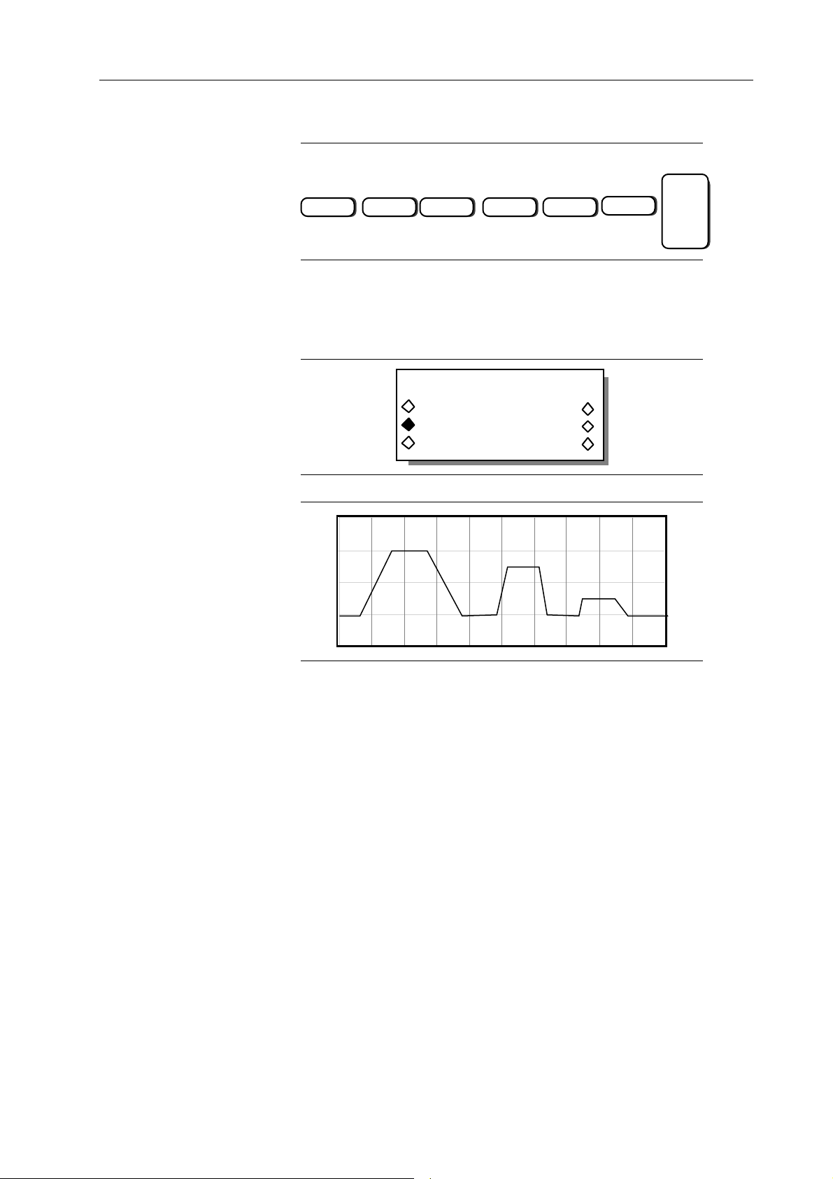
For this example, program the delay to 420 ms by pressing:
ENTER
4 2 EXP
Press F4, “exit,” to return to the Standard Waveform screen.
•
+/-
1
Step 21 Viewing the Pulse Train
First connect the scope and Model 395 as described in paragraph 3.5. Press the softkey
to the left of “pulse-train.”
STANDARD WAVEFORMS
pulse setup …
pulse-train setup …
digtl noise setup …
The scope displays:
3.13 THE MODEL 395 AS A NOISE GENERATOR
Example 12 Setting Up the Signal To Noise Waveform
This example creates a 100 kHz sine waveform with 50% noise. Paragraph 5.5.8,
example 12 contains the remote SCPI programming equivalent of this example. First
setup the Model 395 as described in example 1, steps 1, 2, and 3.
Introduction To The Model 395 3-43
Page 70
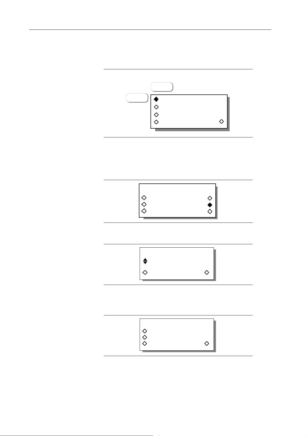
Step 1 Selecting Continuous Mode
To set the operating mode to continuous, press the MODE key to display the Mode
screen:
MODE
F1
continuous
sweep
gated
trig'd, cnt: 0000001
Press F1, “continuous,” to select this mode. Continuous is the default mode.
Step 2. Selecting Signal + Noise Setup
Set up the signal + noise waveform by pressing the STANDARD key under Waveform
Select to display the Waveform screen. Rotate the knob to display “sig+noise setup …”
on the screen.
STANDARD WAVEFORMS
comb setup …
sig+noise setup …
sig+comb setup …
Step 3 Defining the Sequence Length
Select “sig+noise setup” to display the Sequence Length screen.
SEQUENCE LENGTH
63
exit next
Rotate the knob until the screen displays the sequence length: 4095.
Step 4 Setting the Noise Frequency Bandwidth
Press F8, “next,” to advance to the Noise Bandwidth screen.
NOISE FREQUENCY BAND
start: 0.000 Hz
stop : 1.000 MHz
exit next
3-44 Introduction To The Model 395
Page 71
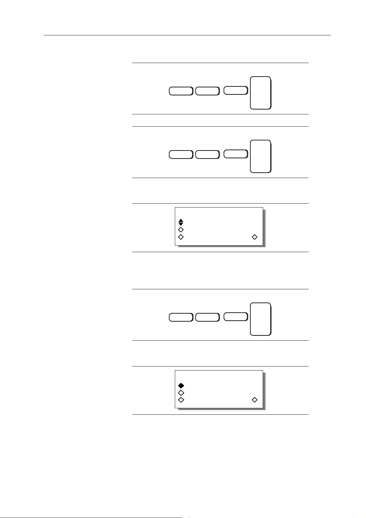
First, set the start frequency to 100 kHz by pressing:
ENTER
1
Next set the stop frequency by pressing F3, “stop,: and entering 2 MHz by pressing:
2
EXP
EXP
5
ENTER
6
Step 5 Defining the Signal
Press F8, “next,” to display the Signal Definition screen.
SIGNAL DEFINITION
name: sine
freq : 500. kHz
exit next
From this screen, you define the frequency and waveform that will be mixed with the
noise.
Press F2, “name:,” until “sine” appears. Next, set the frequency of the sine wave by
pressing F3, “freq.” Then, set the frequency to 100 kHz by pressing:
ENTER
1
EXP
5
Step 6 Setting the Signal to Noise Ratio
Press F8, “next,” to display the Noise/Signal Ratio screen.
NOISE / SIGNAL RATIO
signal: 90 %Vpp
noise: 10 %Vpp
exit next
The ratio is entered as a percentage of the peak to peak value of the selected waveform
(sine in this case) or the noise.
Introduction To The Model 395 3-45
Page 72
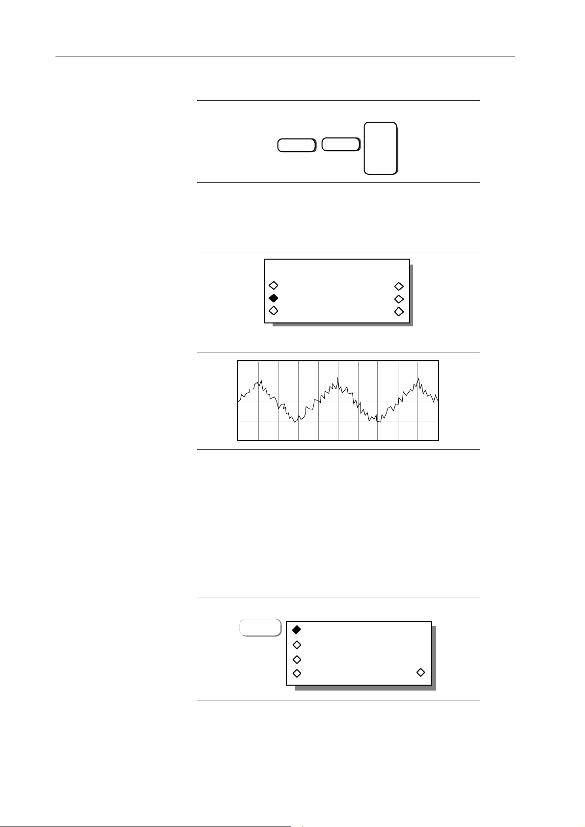
Set the percentage to 50 %Vp-p by pressing:
ENTER
5
Press F4, “exit,” to return to the Standard Waveform screen.
0
Step 8 Viewing Signal To Noise
To view signal to noise, first connect the scope and Model 395 as described in paragraph
3.5.
STANDARD WAVEFORMS
comb setup …
sig+noise setup …
sig+comb setup …
Select “sig+noise” and view the Model 395’s output on the scope:
3.14 THE MODEL 395 AS AN AMPLITUDE MODULATION SIGNAL SOURCE
Example 13 Setting Up Amplitude Modulation
This example produces a 600 kHz 50% Amplitude Modulated Sine wave. This example
requires you to use an external modulating source. Paragraph 5.5.9, example 13 contains
the remote SCPI programming equivalent of this example. First setup the Model 395
as described in example 1, steps 1, 2, and 3.
Step 1 Selecting Continuous Mode
To set the operating mode to continuous, press the MODE key to display the Mode
screen:
F1
continuous
sweep
gated
trig'd, cnt: 0000001
3-46 Introduction To The Model 395
Page 73
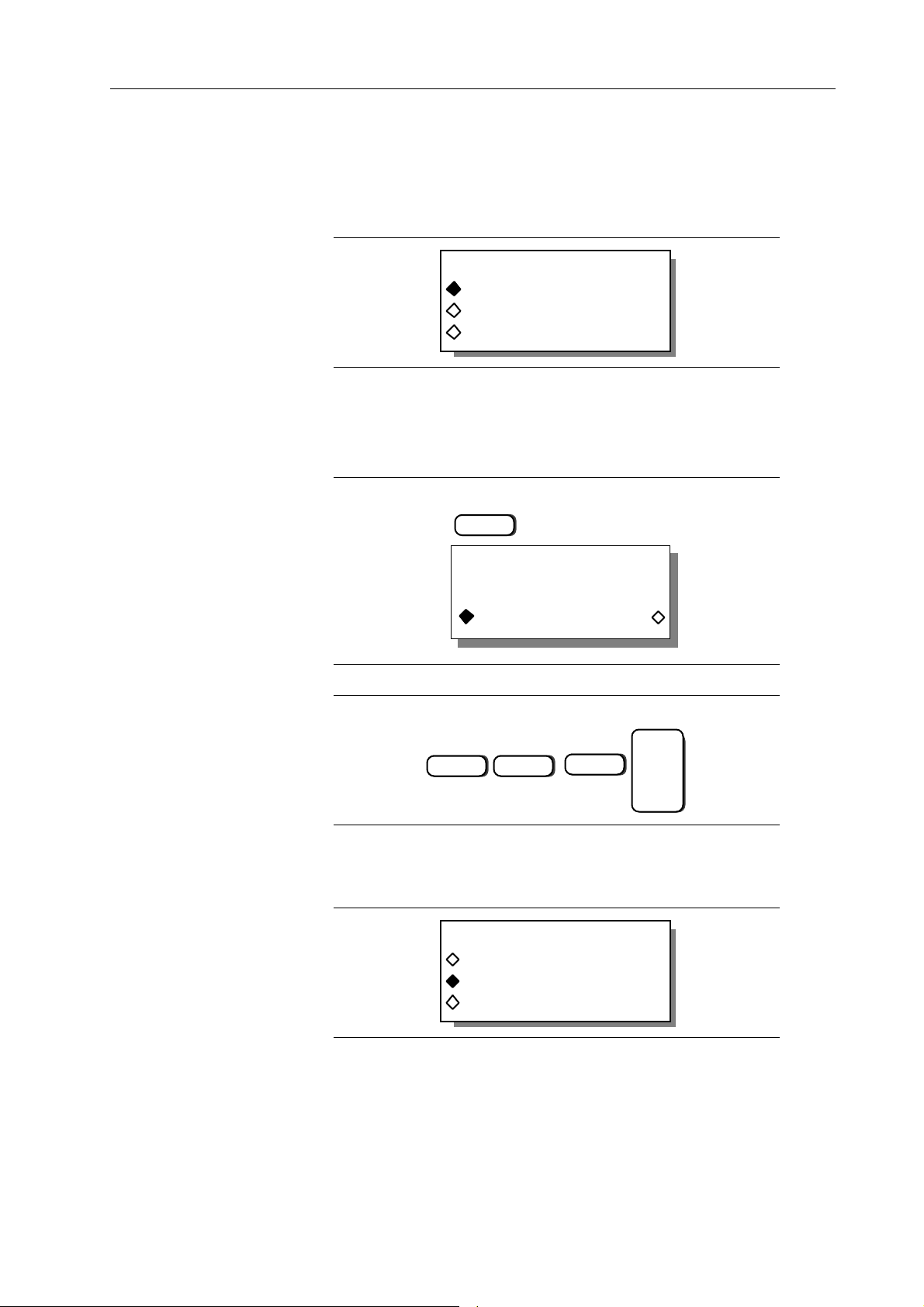
Press F1, “continuous,” to select this mode. Continuous is the default mode.
Step 2. Selecting the Waveform
Select the sine wave by pressing the STANDARD key under Waveform Select to display
the Waveform screen. Rotate the knob to display “sine” on the screen.
STANDARD WAVEFORMS
sine
square
triangle
Select the sine wave by pressing the softkey to the left of “sine.”
Step 3 Setting the Frequency to 600 kHz
Program the frequency of the square wave by pressing the FREQUENCY key to display
the Standard Frequency screen:
FREQUENCY
STANDARD FREQUENCY
1.000000000 kHz
freq period
To change the frequency, press these keys:
ENTER
6
EXP 5
Step 4 Setting Up the AM Input
To enable the AM IN connector and select the AM mode, press the AM IN key which
displays the AM Input Setup screen.
AM INPUT SETUP
off
AM (2.5Vpp=100%)
SCM (5.0Vpp=200%)
Press F3, “AM (2.5Vpp=100%),” to both enable the AM IN connector and switch to the
AM mode.
Introduction To The Model 395 3-47
Page 74

Step 5 Viewing the AM Signal
Connect the scope and Model 395 as described in paragraph 3.5. Setup the external
signal generator to 2 kHz, 1.25 Vp-p sine wave. Connect an external signal generator’s
Function Output to the to the Model 395’s AM IN connector. Be sure to properly
terminate the external signal generator’s Function Output.
Also try to create the AM signal using the Model 395’s internal AM waveform.
The scope displays a 600 kHz “carrier” that is modulated to 50% modulation by a 2 kHz
sine wave.
3.15 THE MODEL 395 SUMMING INPUT
Example 14. Setting Up Summing Input
Example 14 sums an external TTL waveform with analog noise from the Model 395.
Paragraph 5.5.10, example 14 contains the remote SCPI programming equivalent of this
example. First setup the Model 395 as described in example 1, steps 1, 2, and 3.
Step 1 Selecting Continuous Mode
To set the operating mode to continuous, press the MODE key to display the Mode
screen:
F1
continuous
sweep
gated
trig'd, cnt: 0000001
Press F1, “continuous,” to select this mode. Continuous is the default mode.
Step 2. Selecting Analog Noise Setup
Set up analog noise by pressing the STANDARD key under Waveform Select to display
the Waveform screen. Rotate the knob to display “analg noise setup …” on the screen.
3-48 Introduction To The Model 395
Page 75

STANDARD WAVEFORMS
digtl noise setup …
analg noise setup …
comb setup …
Step 3 Defining the Sequence Length
Select “analg noise setup…” to display the Sequence Length screen.
SEQUENCE LENGTH
63
exit next
Rotate the knob until the screen display the sequence length: 4095.
Step 4 Setting the Noise Frequency Bandwidth
Press F8, “next,” to advance to the Noise Bandwidth screen.
NOISE FREQUENCY BAND
start: 0.00 Hz
stop : 1.00 MHz
exit next
First, set the start frequency to 100 Hz by pressing:
ENTER
1
Next set the stop frequency by pressing F3, “stop,” and entering 2 MHz by pressing:
2
EXP
EXP
2
ENTER
6
Step 5 Setting Up Summing Input
To begin setting up the Sum Input, press the SUM IN key and the Model 395 displays
the Sum Input Setup screen.
Introduction To The Model 395 3-49
Page 76

SUM IN SETUP
input: off
atten: -12 dB ( / 4)
atten mode: auto
Enable the Sum In connector by pressing F2 until the “input: on” is displayed. Then press
F3 until the screen displays “0 dB (/1).”
Step 6. Connect the Sum In Signal
Connect the external Sum Source to the Model 395’s Sum In connector, and set the signal
source to 1 kHz, 2 Vp-p sine wave. Connect the Main Out from the Model 395 to
channel 1 on the scope. Sync the scope from the Sum Source. Be sure to properly
terminate the outputs from the Sum Source and Model 395.
3-50 Introduction To The Model 395
Page 77

Front Panel Operation Reference Section 4
4.1 INTRODUCTION
This section contains the front panel operational reference information for the Model 395.
Paragraph 4.2 summarizes the front panel controls and connectors, and paragraph 4.3
describes switches and connectors on the rear panel. Paragraph 4.4 contains the detailed
operation reference information based on front panel keys and their screens.
4.2 FRONT PANEL
Figure 4-1 illustrates the front panel of the Model 395. The figures, referenced in figure
4-1, are described in the following list of figures and tables.
Figure 4-2 Softkeys Table 4-1.
Figure 4-3 Operation Keys Table 4-2.
Figure 4-4 Connector Control Keys Table 4-3
Figure 4-5 Knob and Cursor Table 4-4
Figure 4-6 Numeric Key Group Table 4-5
See Figure 4-2
POWER
ON OFF
100 MHz Synthesized Arbitrary Waveform Generator model 395
F1
F2
F3
F4
DISPLAY STATUSHELP
OFFSET SEQUENCEMODEAMPLITUDEFREQUENCY FILTER
WAVEFORM SELECT WAVEFORM EDIT INSTRUMENTS
F5
BSP
F6
F7
F8
UTILITYSTANDARD ARBITRARY SETUPSCREATE MODIFY
7 8 9 CLEAR
4 5 6 EXPRESET
1 2 3
REMOTE
0 +/-MAN TRIG
2kΩ
(0-10V)
ENTER
TRIG IN SYNC OUT AM INSWEEP OUT SUM IN MAIN OUT
EXTON ON ON ON
ON
2kΩ
50Ω
(±10V)
2.5kΩ
(TTL)
(5Vpp)
See Figure 4-5See Figure 4-6
600Ω
50Ω
(10Vpp)
(10Vpp)
See Figure 4-3 See Figure 4-4
Figure 4-1. Front Panel
Front Panel Operation Reference 4-1
Page 78

1
F1
F2
SYNC OUTPUT SETUP
F5
F6
output: off
F3
F4
DISPLAY
2
mode: auto
src: waveform sync
STATUSHELP
3 4
F7
F8
Figure 4-2. Softkeys, Display, Help, and Status
Table 4-1. Softkeys, Display, Help, and Status
Ref. Name Function
1 F1 - F8 These softkeys select items displayed on screen. A filled
diamond (◆) identifies selected screen items. A hollow
diamonds (◆) identifies non-selected screen items.
Double arrows ( ) identifies additional items are available.
2 DISPLAY This key controls the LCD contrast. There are eleven contrast
levels. Each key press advances the contrast to the next level.
The last level loops to the beginning.
3 HELP This key displays help information for the current screen.
Rotate the knob to display additional help information. Press
the HELP key a second time to exit help.
4 STATUS Press this key to display the current instrument status:
Waveform (function)
Frequency
FCN: sine | std
Waveform Type
Mode
FRQ: 1.000 kHz | swp
Amplitude
AMP: +2.000 Vpp | AM
Modulation
OFS: +0.00 Vdc | EL20
Offset
Filter
4-2 Front Panel Operation Reference
Page 79

1 2 3 4 5 6
OFFSET SEQUENCEMODEAMPLITUDEFREQUENCY FILTER
WAVEFORM SELECT WAVEFORM EDIT INSTRUMENT
UTILITYSTANDARD ARBITRARY SETUPSCREATE MODIFY
POWER
ON OFF
7 8 9 10 11 12
13
Figure 4-3. Operation Keys
Table 4-2. Operation Keys
Ref Name Function
1 FREQUENCY Press this key to display the current frequency or period of the
selected waveform. For Arb waveforms, the screen displays
the sample frequency or period as well as waveform frequency
or period. To change the value, use the knob or front panel
keypad. For details, see paragraph 4.4.5 - Frequency.
2 AMPLITUDE Press this key to display the current Main Output amplitude
level. Use the softkeys to display the level in Volt peak to
peak, (Vp-p), Volt RMS (V
), Volt peak (Vp), and dBm.
RMS
To change the level, use the knob or front panel keypad. The
Model 395 assumes the output signal is terminated into 50Ω.
Maximum amplitude is ±10 Vp-p. Refer to paragraph 4.4.1
- Amplitude.
When using pulse waveform, Amplitude sets the upper level
of the pulse.
3 OFFSET Press this key to display the current dc offset value relative to
the waveform baseline. In the dc function (waveform), the
screen displays the output level. The maximum offset range
is ±5.00 Vdc into 50Ω. Refer to paragraph 4.4.7 - Offset for
additional details.
When using pulse waveform, Offset sets the lower level of the
pulse.
4 MODE This key displays the current Model 395 operating mode.
There are four modes: Continuous, Sweep, Gated, and
Triggered. Use the softkeys to select the mode. Refer to
paragraph 4.4.6 - Mode for details.
Front Panel Operation Reference 4-3
Page 80

Table 4-2. Operation Keys (Continued)
Ref Name Function
5 SEQUENCE Use this key to display the Sequence Edit screen. From this
screen, link waveforms in a sequence, setup advance trigger
conditions, select waveform loop counts, and start or stop
the sequence. Also, see paragraph 4.4.10 - Sequence.
6 FILTER This key displays available output filters.
20 MHz Elliptic filter
40 MHz Elliptic filter
10 MHz Bessel filter
No Filter
For more information, see paragraph 4.4.4 - Filter.
7 STANDARD This key lists the Model 395’s standard, pulse, noise, and
sequence waveforms. Use the softkeys to select the desired
waveform. Rotate the knob to display additional waveforms. Selecting “arb” displays all programmed Arbitrary
waveforms. Refer to paragraph 4.4.12, Standard Waveforms
for additional details.
8 ARBITRARY Press this key to list programmed Arbitrary (user-defined)
waveforms. Use the soft keys to select any of these
waveforms. Rotate the knob or press the cursor keys to
display additional waveforms. Refer to paragraph 4.4.3 Arbitrary Waveforms.
9 CREATE This key allows you to create arbitrary waveforms from
scratch (blank) or from existing waveforms (copy). Refer
to paragraph 4.4.3 - Arbitrary Waveforms for details.
10 MODIFY Press this key to modify existing Arbitrary waveforms.
Utilize the Modify screen to edit, rename, and resize a
waveform, as well as, set the start and stop address for the
waveform. Refer to paragraph 4.4.3 - Arbitrary Waveforms.
11 SETUPS Press this key to store and recall complete instrument
setups. Use the screen to save a new setup, to recall an
existing setup, or to delete any existing setup. Refer to
paragraph 4.4.11 - Setup.
12 UTILITY Press this key to list the Model 395 utility screens. From
this screen perform the unit’s calibration procedure; view
system information which includes firmware revision and
memory size; power-on configures the power on setup;
calibration leads you through the Model 395 calibration
procedure; and DSO upload configures the unit for DSO
upload (GPIB/Direct DSO Waveform Transfer Option 001
required). For details refer to paragraph 4.4.18 - Utility
4-4 Front Panel Operation Reference
Page 81

Table 4-2. Operation Keys (Continued)
Ref Name Function
13 POWER This switch turns the Model 395 ON and OFF. Press the
switch in to turn the unit ON. Press the switch again to turn
OFF the Model 395. When in the off position, ac line power
is disconnected from the internal power supply circuits.
The Model 395 requires at least a 20 minute warm up before
specifications apply.
1 2 3 4 5 6
(0-10V)
TRIG IN SYNC OUT AM INSWEEP OUT
1kΩ
EXTON ON ON ONON
2kΩ
(±10V)
50Ω
(TTL)
2.5kΩ
(5Vp-p)
SUM IN
(10Vp-p)
MAIN OUT
600Ω
(10Vp-p)
50Ω
Figure 4-4. Connector Control Keys
Table 4-3. Connector Control Keys
Ref Name Function
1 SWEEP OUT Press this key to display the Sweep Setup screen from which
you can define Sweep Range, Sweep Time, Sweep Type, and
Sweep Spacing, and Sweep Marker.
In addition, use this screen to define the sweep marker and to
select manual (knob) sweep operation.
Refer to paragraph 4.4.15 - Sweep for additional information.
Sweep Out This output connector supplies a linear sweep horizontal ramp
(0 to 10V) with a level proportional to sweep time. A lit
indicator means the output is on. Output impedance is 2kΩ.
2 TRIG IN Press this key to setup trigger parameters. Select internal or
external (Trig In BNC or Man Trig key) trigger source. Select
the trigger slope and level for external trigger. Plus, set the
repetition rate for internal trigger source.
See paragraph 4.4.17 - Trigger for additional information.
Trig In This is the input connector for external trigger source. Input
impedance is 2kΩ. Level range is ±10V.
3 SYNC OUT Press this key to turn the Sync Out on or off and to select the
sync source: trigger, pen lift, waveform sync, pos’n marker,
sweep marker, burst done, and loop done.
See paragraph 4.4.16 - Sync Out for additional information.
Sync Out This is the Sync Output connector which is selected using
SYNC OUT key. Output is TTL into 50Ω.
Front Panel Operation Reference 4-5
Page 82

Table 4-3. Connectors and Control Keys (Continued)
Ref. Name Function
4 AM IN Press to display the Amplitude Modulation setup screen.
Select AM or SCM (suppressed carrier modulation).
Also refer to paragraph 4.4.2 - Amplitude Modulation.
AM In This connector receives the modulation signal input for AM
and SCM. Indicator is lit when AM or SCM is selected. Input
impedance is 2.5kΩ. For more information, refer to paragraph
4.4.2.- Amplitude Modulation.
5 SUM IN This key allows the summing of an external signal with the
selected waveform of the Model 395 and the setting of the
output attenuators.
For details, check the paragraph 4.4.14.
Sum In This is the input connector for the external summing signal.
Input impedance is 600Ω
6 MAIN OUT This key enables or disables the MAIN OUT connector.
Output impedance is 50Ω.
Main Out This connector supplies the waveform output signal. A lit
indicator signifies the output is turned ON. Output impedance
is 50Ω. Output level is up to 10 Vp-p into 50Ω termination.
4-6 Front Panel Operation Reference
Page 83
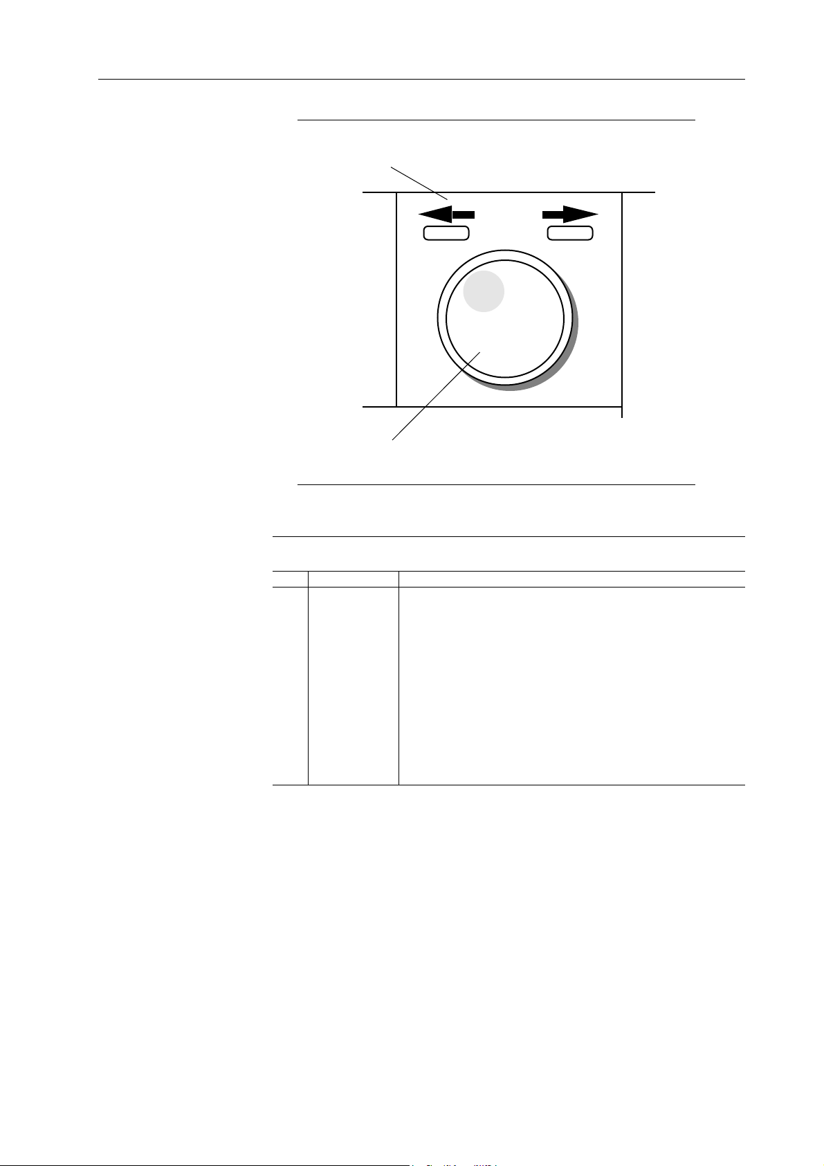
1
2
Figure 4-5. Knob and Cursor
Table 4-4. Connectors and Control Keys
Ref Name Function
1 Cursor keys Pressing the cursor keys moves the cursor position to the left
(<-) or to the right (->). The knob changes values of the digit
positioned over the cursor. The cursor keys can also be used
to scroll additional screen items.
2 Knob Use the knob to change numeric values and to scroll through
items displayed on the screen. Clockwise rotation increases
the value. Counter clockwise rotation decreases the value.
When menus contain additional items, as indicated by a
double-head arrow, use the knob to display additional screens.
Front Panel Operation Reference 4-7
Page 84
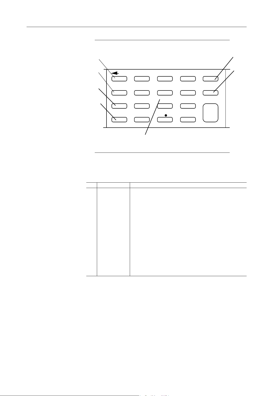
1
7
2
BSP
3
4
RESET
REMOTE
MAN TRIG
7
4 5 6
1
0
8
2
9
3
+/-
CLEAR
EXP
ENTER
6
5
Figure 4-6. Numeric Keys Group
Table 4-5. Numeric Keys Group
Ref. Name Function
1 <- BSP Backspace moves the cursor left one character and deletes
that character.
2 RESET Use this key to reset all parameters to default values, to delete
Arbitrary waveforms, or to delete all stored setups and DSO
drivers.
3 REMOTE Use this key to select a remote interface and to set up interface
parameters. Refer to paragraph 4.4.8.
4 MAN TRIG Press to this key to manually trigger the generator. Refer to
paragraph 4.4.17 - Triggering.
5 Number keys Use these keys to enter numeric values.
6 EXP Use this key to enter an exponential value. Numbers entered
after EXP are treated as exponents.
7 CLEAR Use to erase an entire entry. Press ENTER to restore to last
legal entry.
4-8 Front Panel Operation Reference
Page 85
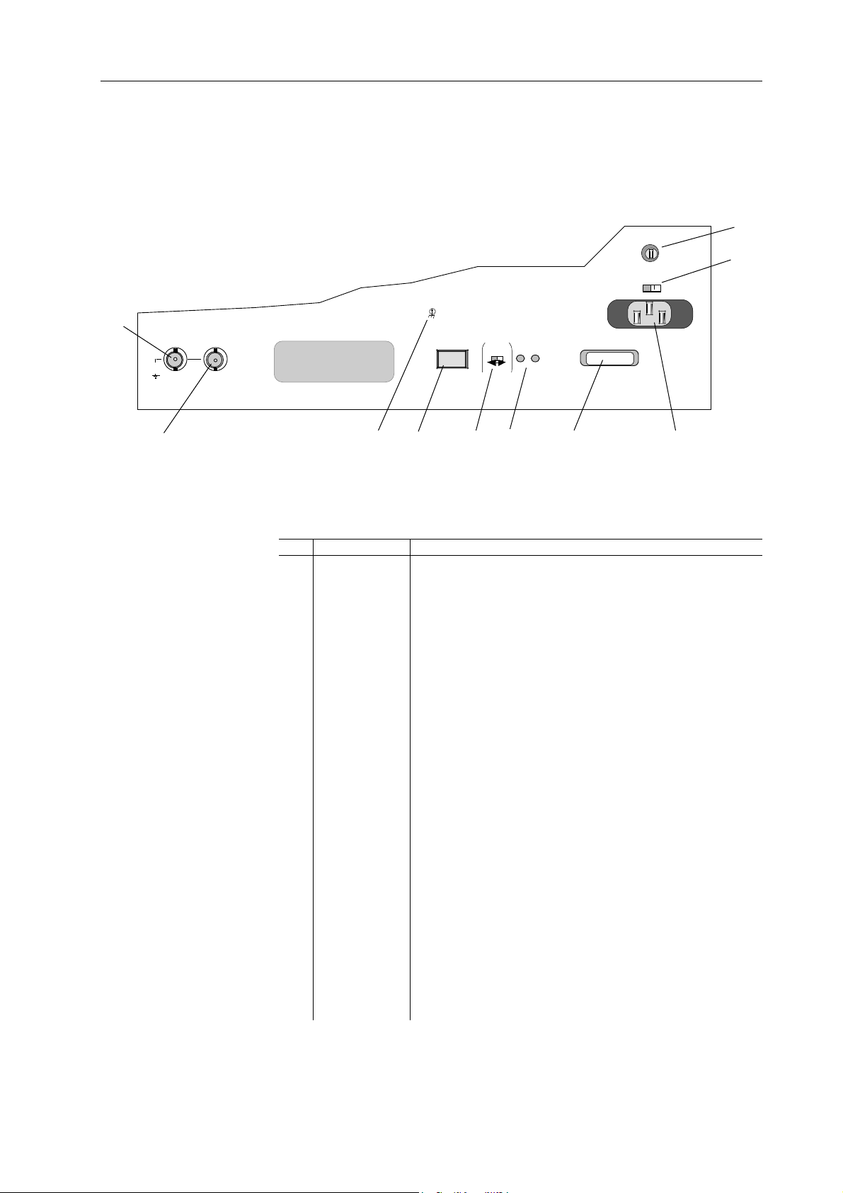
4.3 REAR PANEL
10
1
Max Float
42Vpk
REF OUT
TTL/50Ω 1Vp-p/5kΩ
10MHz
10MHz
REF IN
Figure 4-7 illustrates the rear panel of the Model 395. Numbers in this figure identify
the connectors described in table 4-6.
9
CAL ENABLE
RS-232
NORM - CAL
BATTERY
TEST
BAT GND
IEEE-488
3
2
4 5
6 8
7
Figure 4-7. Rear Panel Connectors
Table 4-6. Rear Panel Connectors
Ref Name Function
1 REF OUT This connector provides a buffered 10 MHz TTL internal
system clock output. Also, this connector can supply a
buffered reference output with an external 10 MHz clock
connected to REF IN. Output signal level is approximately
1.5 Vp-p into 50Ω.
Also refer to paragraph 4.4.5 for additional information.
2 REF IN Use this connector as an optional external reference source
input. Input frequency must be 10 MHz ±5%. Input level
must be between 1Vp-p and 10 Vp-p with 40 to 60% duty
cycle. Input impedance is >1kΩ (ac coupled).
Also refer to paragraph 4.4.5 for additional information.
3 Earth Gnd. Earth ground connection.
4 RS-232 Use this connector to connect the Model 395 to a computer for
remote operation. For more information on RS-232 interface
and its operation, refer to paragraph 2.7.1 and section 5 of this
manual.
5 CAL ENABLE IMPORTANT - This switch is normally covered by a
Calibration Sticker. Only personnel authorized to perform a
calibration procedure should remove this sticker. An
improperly performed calibration procedure could severely
affect the performance of this instrument.
Use this switch to enable or disable the Model 395 internal
calibration procedure. The switch should be in the NORM
position during normal operation.
Change the switch to CAL when performing calibration.
Front Panel Operation Reference 4-9
Page 86
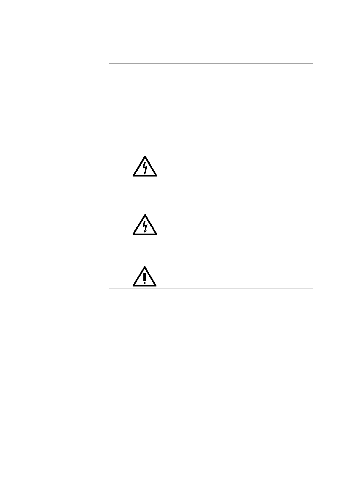
Table 4-6. Rear Panel Connectors (Continued)
Ref Name Function
6 BATTERY TEST Use these test points to measure the internal battery of the
Model 395. A normal battery should measure between + 3.2
and +2.7 Vdc.
7 IEEE-488 Optional - Use this connector to connect the Model 395 to a
computer for remote operation or a digital storage oscilloscope
(DSO) for direct DSO Waveform Transfer. For more
information on IEEE-488 interface and its operation, refer to
paragraph 2.7.2 and section 5 of this manual. For information
on DSO waveform transfer, refer to appendix F.
8 Power Con. Use this connector to connect the Model 395 to the ac supply.
ALWAYS ENSURE THAT THE INSTRUMENT IS
CONNECTED TO EARTH/PROTECTIVE GROUND.
SEE SAFETY ISSUES SECTION AT THE FRONT OF
THIS MANUAL.
9 Line Voltage Use this switch to select the line voltage to match the primary
power source.
SEE SECTION TWO AND THE SAFETY ISSUES SECTION
AT THE FRONT OF THIS MANUAL.
Switch Setting Voltage Range
115 (Vac) 90 to 132 Vac
230 (Vac) 198 to 252 Vac
11 Fuse The Model 395 primary power fuse.
SEE SECTION 2 AND THE SAFETY ISSUES SECTION
AT THE FRONT OF THIS MANUAL.
Line Voltage Fuse
115 1 A Time delay
230 0.5 A Time Delay
4-10 Front Panel Operation Reference
Page 87

4.4 REFERENCE
4.4.1 AMPLITUDE
These paragraphs are organized by front panel keys in alphabetical order.
Paragraph Subject
Number
4.4.1 Amplitude
4.4.2 AM In (Amplitude Modulation)
4.4.3 Arbitrary Waveforms
4.4.4 Filter
4.4.5 Frequency
4.4.6 Mode
4.4.7 Offset
4.4.8 Remote
4.4.9 Reset
4.4.10 Sequence
4.4.11 Setups
4.4.12 Standard Waveforms
4.4.13 Status
4.4.14 Sum In (Summing)
4.4.15 Sweep
4.4.16 Sync Out
4.4.17 Trigger
4.4.18 Utility
Amplitude controls the voltage level of the signal from the MAIN OUT connector.
Amplitude is variable between -10.0 Vp-p and +10.0 Vp-p into 50Ω in 10 mV steps with
3 digits of resolution. A negative “-” amplitude means the signal is inverted relative
to the Sync Out signal.
The Model 395 displays Amplitude in units of Vp-p, Vp, Vrms, or dBm. Maximum
levels depend on the programmed waveform and units selected; see table 4-7.
The amplitude of Arbitrary waveforms and waveform sequences depend on the data
values entered while creating the waveform. Thus, the actual amplitude output for
Arbitrary waveforms and waveform sequences may be less than the programmed
amplitude.
Front Panel Operation Reference 4-11
Page 88

Table 4-7. Maximum Amplitude Vs Waveform
Waveform Vp-p Vp Vrms dBm
Sine 10.0 5.00 3.54 +24.0
Square 10.0 5.00 5.00 +27.0
Triangle 10.0 5.00 2.89 +22.2
+Ramp 10.0 5.00 2.89 +22.2
-Ramp 10.0 5.00 2.89 +22.2
sin (x)/x 10.0 5.00 NA NA
+H-Sine 10.0 5.00 1.77 NA
-H-Sine 10.0 5.00 1.77 NA
Random 10.0 5.00 5.00 NA
Pulse ±5.00V Upper level (Offset - lower level)
Pulse Train ±5.00V Pulse level each pulse. Offset baseline)
Digital Noise 10.0 5.00 NA NA
Analog Noise 10.0 5.00 NA NA
Comb 10.0 5.00 NA NA
Sig. + Noise 10.0 5.00 NA NA
Sig. + Comb 10.0 5.00 NA NA
AM 10.0 5.00 NA NA
FM 10.0 5.00 NA NA
Arb Waveform 10.0 5.00 NA NA
Sequence 10.0 5.00 NA NA
Notes
All values measured into 50Ω termination
NA - Not Available
Amplitude + Offset Limits
If Amplitude plus Offset exceeds 5Vp, the screen will display an error message:
WARNING:AMPL+OFST> 5V
ofst: +2.50 Vdc
WARNING:AMPL+OFST> 5V
ampl: +3.00 Vp
Vpp Vp
Vrms dBm
The upper screen will be displayed when Offset is selected; and the lower screen when
Amplitude is selected. To correct the problem, change the amplitude value or the offset
values.
Programming Amplitude
To program Amplitude (see figure 4-8), press the AMPLITUDE key which displays
the Amplitude screen. Change the value using the knob or keypad. Changing the sign
of the output level inverts the waveform relative to the Sync Out signal. Changing the
amplitude sign in dBm does not invert the waveform but will affect the output level.
4-12 Front Panel Operation Reference
Page 89

To change voltage units, press these softkeys:
Vp-p F3
Vrms F4
Vp F7
dBm F8
AMPLITUDE:
+1.00 Vp
Vpp Vp
Vrms dBm
Figure 4-8. Amplitude Programming
Vp-p
“Vpp” (voltage peak-to-peak) displays the output as the level between the positive and
negative peaks of the waveform.
Vrms
“Vrms” displays voltage root-mean-square value of the waveform. Not all waveforms
display amplitude in Vrms.
Vp
“Vp” displays the maximum peak value of the waveform.
dBm
“dBm” displays output amplitude levels in decibels above 1 milliwatt. Not all
waveforms display amplitude in dBm.
Also see:
Paragraph 4.4.7 Offset
Front Panel Operation Reference 4-13
Page 90

4.4.2 AM IN (AMPLITUDE MODULATION AND SCM)
The Model 395 supports Amplitude Modulation (100%) and Suppressed Carrier
Modulation (200%). The unit receives its modulating signal via the AM IN connector.
An external signal controls the level of the signal at the MAIN OUT connector. All
waveforms, including arbitrary waveforms, can be modulated. Amplitude modulation
works in all operating modes. Figure 4-9 illustrates the AM In screen.
AM INPUT SETUP
off
AM (2.5Vpp=100%)
SCM (5.0Vpp=200%)
Figure 4-9. AM In Screen
Note
The Model 395 also provides internal AM and SCM which is
accessible through the Standard Waveform’s screens. See
paragraph 4.4.12.18.
OFF
Press F2, “off,” to disconnect the AM Input from the Model 395. See figure 4-9.
AM (Amplitude Modulation)
An input of 2.5 Vp-p produces 0% to 100% modulation of the programmed amplitude.
In other words a +1.25V input produces 100% programmed amplitude, and -1.25V
input outputs 0% programmed amplitude. With a 0V modulating signal, the MAIN
OUT signal is half the programmed amplitude.
To Amplitude Modulate the Model 395,
Select the Waveform;
Program the frequency;
Program the Amplitude;
Set up the operating Mode.
Press the AM IN key and select (F3) “ AM (2.5Vpp=100%).” Connect the modulating
source to the AM IN connector (figure 4-10).
4-14 Front Panel Operation Reference
Page 91

FREQUENCY
WAVEFORM SELECT
STANDARD ARBITRARY
ON OFF
AMPL
OFFSET SEQUENCEMODE
WAVEFORM EDIT INSTRUMENTS
CREATE MODIFY
100 MHz Arbitrary Waveform Synthesizer Model 395
FILTER
SETUPS
UTILITY
7 8 9
4 5 6
1 2 3
0
+/-
EXTON ON ON ON
ON
2kΩ
2kΩ
50Ω
(0-10V)
(±10V)
(TTL)
2.5kΩ
600Ω
50Ω
(5Vpp)
(10Vpp)
(10Vpp)
Modulation
Source
Terminate
If Needed
50Ω
Termination
Output
Device
Figure 4-10. AM/SCM Setup
NOTE
Failing to properly terminate the Modulation Source at the
AM IN connector could cause inaccurate modulation levels.
Also see:
Amplitude
MAIN OUT
Frequency
Mode
SCM (Suppressed Carrier Modulation)
SCM produces an output whose level is dependent on the modulation input signal. With
0V input or no modulation input, the MAIN OUT signal is 0Vp-p. For full programmed
output, drive the AM IN with 2.5V. +2.5V produces an in phase output, and -2.5V
generates an out of phase output.
Front Panel Operation Reference 4-15
Page 92

To SCM the Model 395,
10 points to 65536 points
Programmed
Ampltude
Select the Waveform;
Program the frequency;
Define the Amplitude;
Set up the operating Mode.
Press the AM IN key and select (F4) “ SCM (5Vpp=200%).” Connect the
modulating source to the AM IN connector (figure 4-10 ).
Also see:
Amplitude
MAIN OUT
Frequency
Mode
4.4.3 ARBITRARY WAVEFORMS
4.4.3.1 Introduction
Arbitrary waveforms are individual data points at addresses stored in internal memory
of the Model 395. To generate the Arbitrary waveform a clock steps the memory
addresses and the data is converted to an analog voltage. The analog voltage is
amplified by an output amplifier and routed to the Main Out connector. By controlling
the clock period and the total number of points in each cycle, the frequency of the
waveform can be increased or decreased.
In the Model 395, Arbitrary (Arb) Waveforms or user-defined waveforms can be
identified by a user-defined name and number of horizontal points (waveform size): 10
to 65,536 points (256K optional). Vertical size, 4096 points (+000; -2048, +2047),
represents the maximum peak-to-peak level at the programmed amplitude.
Enter waveforms using the front panel keys and screens or by sending data over the RS232 or optional GPIB interfaces. Figure 4-11 illustrates Arb waveform parameters.
The Model 395 stores arbitrary waveforms in battery backed memory. The number of
waveforms that can be stored depends on the size or the number of points in each
waveform.
Data Points
+2047
+0000
-2048
Waveform Size
100%
Programmed
Ampltude
0%
4-16 Front Panel Operation Reference
Figure 4-11. Arb Waveform Basics
Page 93

Arb Waveform Terms
Horizontal Size
Number of horizontal points is the time component of the waveform. Minimum size is
10 points, and a maximum size is 65536 points (131,072 points with extended memory).
The horizontal size must always be an even number.
Waveform Address
Each horizontal point on an Arb waveform is defined by a discrete address. Addresses
start a 0000 thus the ending address always appears to be one less than the number you
programmed. For example, a 10 point waveform starts at 0 and ends at 9.
Arbitrary Waveforms and Frequency
A typical Arb waveform uses only a part of memory in the Model 395. These waveforms
are stored as files in the unit’s memory. Each file has a name and size (number of points).
The size of these waveforms combined with the scan speed (sample clock frequency)
give the waveform frequency. In example 2 in section 3, the waveform, GRAY, is 2540
points long and has a period of 64 µs. Using this information we can calculate the sample
clock used by the Model 395.
Waveform Size * Sample clock period = waveform period
Solving for Sample clock;
Sample clock period = Waveform period / Waveform size
Thus, Sample clock period = 64 µs / 2540 points
gives, Sample clock period = 25.20 ns
or, Sample clock = 39.69 MHz.
Data Value
Each horizontal point in an Arb waveform is defined by a discrete data or amplitude
value. Data values range between -2048 and +2047 about +0000.
Arbitrary Waveforms and Amplitude
When playing Arbitrary waveforms, the output amplitude will depend on the data
values. For example, creating a waveform that contains data points ranging from -2048
to +2047 will produce an output 100% of the programmed peak to peak amplitude.
If the waveform was created using a portion of the data points, say 0000 to 2048, the
output will be 50% of the programmed amplitude.
4.4.3.2 Creating Waveforms
Create an Arb waveform by giving the waveform a name, defining its size, and editing
the waveform. Also, existing standard or arbitrary waveforms can be copied or
renamed. Pressing the CREATE key displays the Create New Waveform screen; see
figure 4-12. From this screen either create a new blank waveform or copy and rename
an existing waveform.
CREATE NEW WAVEFORM
(avail mem: 57868)
create blank …
create from copy …
Figure 4-12. Create New Waveform
Front Panel Operation Reference 4-17
Page 94

Create Blank Waveforms
The CREATE screen (figure 4-13) allows you to name the new waveform and define
its size; see name and size below. Selecting “create” (F8) advances to the MODIFY
screen. Select “cancel” (F4) to return to the Create New Waveform screen.
CREATE: "wv1_____"
size: 1024
(max: 64512)
cancel create
Figure 4-13. Create Blank
Name
Enter names using the knob or numeric keypad. The Model 395 provides a default name
of “wv(n)” with wv1 being the first default name. Use the knob or keypad to enter or
change the name. Names can contain up to eight characters, and the characters can be
alpha and numeric. The first character in the name must always be a letter.
Size
Size (F2) defines the number of points in the waveform. Minimum number of points
allowed is 10, and maximum number of points is 65536 (standard memory) or 131,072
with extended memory installed. Default is 1024 points. After selecting “size” (F3)
use the keypad or knob to enter or change the number of points.
4.4.3.3 Create From Copy
Selecting “create from copy” duplicates an existing waveform and stores the copy
under a new name. See figure 4-14. Hint - use create from copy to copy a standard
waveform which can be edited using “Edit Waveform.”
create "wv1_____"
from: sine
size: 4096
cancel create
Figure 4-14. Create From Copy
4-18 Front Panel Operation Reference
Page 95

Press F2 to select the waveform to copy. Use the knob or cursor keys to scroll through
the list of waveforms stored in memory. Both standard and arbitrary waveforms can be
copied.
To enter the name of the new waveform press F1 and use the knob or keypad to enter the
name. Names can have up to eight characters. The first character in the name must
always be a letter (a … z).
Press F3, “size,” to set the number of points in the new waveform. Minimum number
of points is 10, and the maximum is 65536 points (131,072 points with extended
memory). Enter the size using the knob or keypad. Default size shown is 1024 points
or the amount of points left if memory is low. When the waveform is enlarged (original
number of points less than new number of points), the Model 395 adds (interpolates)
points. Shrinking the waveform (original number of points greater than new number of
points) the Model 395 removes points from the waveform which could loose significant
waveform data.
Note
Once a waveform has been resized to a number of points
less than the original size, it will never regain the same
identical waveform shape as the original size.
Select “create” (F8) to accept the copied waveform and return to the Create New
Waveform screen.
Select “cancel” (F4) to return to the Create New Waveform screen without copying the
waveform.
4.4.3.4 Modifying Waveforms
The Model 395 allows modification of existing arbitrary waveforms. See figure 4-15.
Resize allows increasing or decreasing the number of points in a waveform. Rename
allows you to assign the waveform a new name. “Limits “ define a part of an existing
waveform to output. Delete erases waveforms. Use Edit Waveform to modify
waveforms using the Model 395’s editing functions.
resize… rename…
Figure 4-15. Modify Waveforms
Select the waveform for modification by pressing F1. Use the knob, cursor keys, or F1
to scroll through the list of arbitrary waveforms.
MODIFY: wave1
delete… limits…
edit waveform…
Front Panel Operation Reference 4-19
Page 96
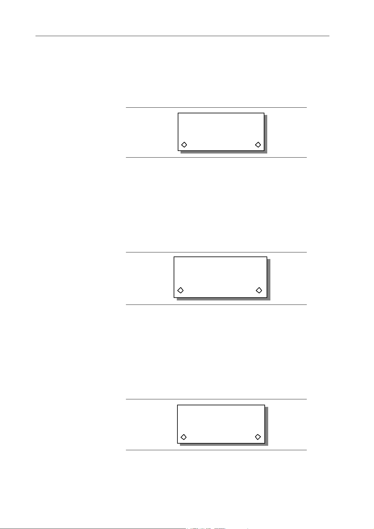
Resize Waveform
“resize” (F2) changes the number of points in the selected waveform. Use “new size”
(F3) to enter of the new size value; use the knob or keypad to enter the value. When the
waveform size is enlarged, the Model 395 adds (interpolates) points. If the waveform
size is shrunk, the Model 395 removes points. Reducing the size of the waveform could
cause the waveform to loose significant data. See figure 4-16.
Note
There is no “undo” for resize. Consider making a copy of the
waveform before resizing it.
Rename Waveform
“rename” (F6) allows changing the name of any arbitrary waveform. Names can have
up to eight characters. The first character in a name must always be a letter (A …Z). To
rename a waveform, select “rename“ from the Modify screen. On the Rename screen,
use the knob or keypad to enter the new name. See figure 4-17.
RESIZE: wave1
(old size: 1024)
new size: 512
cancel resize
Figure 4-16. Resize Waveform
Delete Waveform
“delete“ (F3) allows erasing of the selected arbitrary waveform. To delete a waveform,
select the waveform (F1) from the Modify screen. Then select “delete” (F3) on the
Modify screen. Select “delete” (F8) on the Delete screen to erase the waveform. Press
“cancel” (F4) to return to the Modify screen without deleting the waveform. See figure
4-1.
Rename: wave1
as: "test1________"
cancel rename
Figure 4-17. Rename Waveform
NOTE!
Deleted waveforms cannot be recovered.
Delete waveform
"banjobit"
?
cancel delete
4-20 Front Panel Operation Reference
Figure 4-18 . Delete Waveform
Page 97
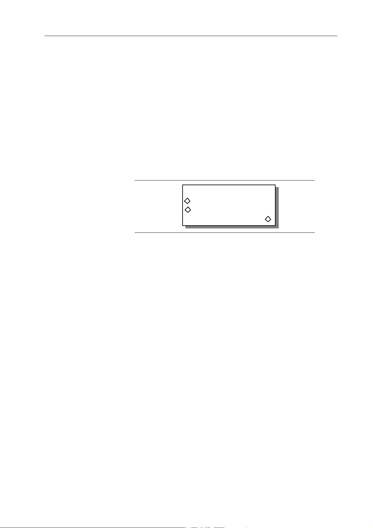
Limits
“limits” (F7) selects portions of an arbitrary waveform. To change the limits, select the
addresses to “start” and “stop” the waveform. There must be at least 10 points between
the start and stop address. See figure 4-19.
To set the limits, first select the waveform (F1) from the Modify screen. Next select
“limits…” (F7) to display the Limits Of screen. Press “start adrs” (F2) or “stop adrs” (F3)
and use the keypad or knob to change the address. Press F8 “done” to change the limits
of the waveform and return to the Modify screen. From then on the waveform uses these
limits until new limits are defined.
Note
The whole waveform still exists, you have only selected a
portion or “limit” of the waveform to run.
The Start address must be an even number, and the Stop
address must be an odd number.
LIMITS OF: xy3
start adrs: 0
stop adrs: 512
(size: 1024) done
Edit Waveform
Select “edit waveform …” to modify a waveform (see figure 4-20) by changing one
point at a time (point edit), by drawing lines between two points (line draw), or by
inserting all or part of an existing waveform (wave insert) into the selected waveform.
In addition, portions of the waveform can be selected and the peak to peak level changed
using waveform amplitude, or baseline adjusted using waveform offset. Plus, copy
portions of a waveform and insert the copy within the same waveform. Also, from this
screen define position markers for use as Sync Output.
Figure 4-19. Waveform Limits
Front Panel Operation Reference 4-21
Page 98

EDIT FUNCTIONS
point edit…
line draw…
wave insert …
block copy …
wvfm ampl …
wvfm offset … done
pos'n mrkrs …
Figure 4-20. Waveform Edit
(actual screen will display only four lines at a time)
Point Edit
“point edit” programs the data value at a single point in the waveform. See figure 4-21.
To modify a point, select “address” (F3) and use the knob or keypad to enter the address
to be changed. Change the data by selecting “data” (F7) and using the knob or keypad
to enter the desired data value (+0000; -2048, +2047). Changing the data value
automatically updates the waveform.
POINT EDIT
(adrs, data)
(00000, +0000)
exit next point
Figure 4-21. Point Edit
Selecting “next point” (F8) automatically advance to the next address. Select “exit” (F4)
to return to the Select Edit Waveform screen without advancing to the next address.
Figure 4-22 illustrates an example of point edit. Also, paragraph 3.7, example 5
demonstrates the point edit.
+
Data
Points
0
-
Address Points
Figure 4-22. Point Edit Illustration
4-22 Front Panel Operation Reference
Page 99
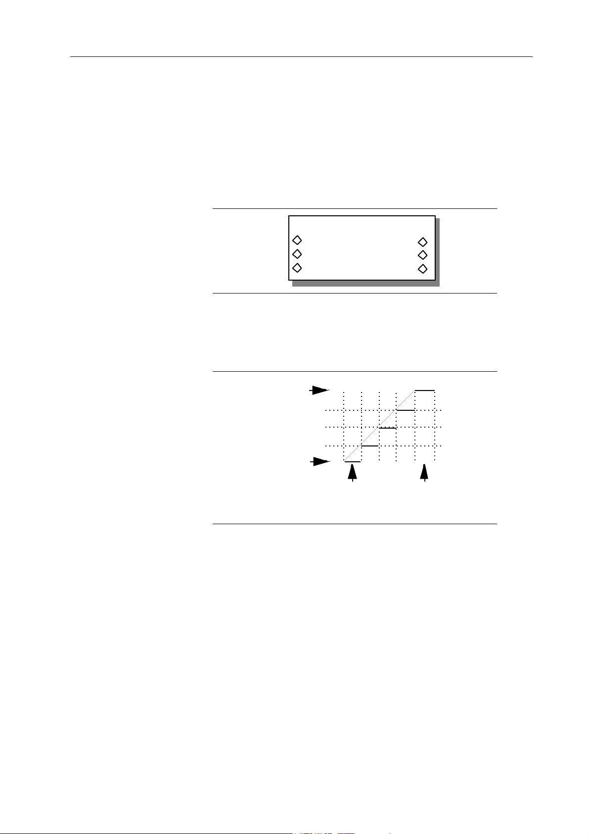
Line Edit
“line edit” draws a line between two points in an Arb waveform. Line edit requires the
user to enter address and data values for the first, “fm,” point and the last, “to,” point of
the line. See figure 4-23.
To use line edit, select the “fm adrs” (F2) and enter the value. Select from data (F6) and
enter the value. Next, select the” to adrs” (F3) and enter the value, and select to data (F7)
and enter the value (+0000; -2048 to +2047). Use the knob or keypad to change values.
The Model 395 automatically swaps the two addresses if the “from” address is less than
the “to” address.
LINE (adrs ,data)
fm: (000000 ,+2058)
to: (000200 ,+0000)
exit draw line
Figure 4-23. Line Draw
Select “draw line” to draw the line segment between the “to” and “from” points. Select
“exit” to return to the Edit Waveform screen. Selecting Exit does not draw a line. Figure
4-24 illustrates an example of line draw. Also, paragraph 3.7, example 2 demonstrates
the line draw technique.
To
Data
From
Data
From
Address
Figure 4-24 . Line Draw Illustration
To
Address
Wave Insert
Wave Insert places waveforms between programmable start and stop points. Both
standard and arbitrary waveforms can be inserted in the new waveform. These
waveforms cannot be used with waveform insert: pulse, pulse-train, digital noise,
analog noise, comb, signal plus noise, signal plus comb, AM, FM, and sequence.
Portions of arbitrary waveforms can be selected (start and stop points) and inserted in
the waveform. Figure 4-25a illustrates the standard waveform insertion screen, and
figure 4-25b illustrates the arbitrary waveform insertion screen. Paragraph 3.7, example
4 demonstrates the waveform insert technique.
Front Panel Operation Reference 4-23
Page 100

sine --> banjo
------ strt 000000
------ stop 000512
exit insert
Figure 4-25a. Insert Standard Waveforms
wav5 --> banjo
000128 strt 000000
000640 stop 000512
exit insert
Figure 4-25b. Insert Arbitrary Waveform
Select the waveform to be inserted by pressing F1, and use the knob, cursor, or F1 key
to scroll through the list. The displayed waveform is inserted into the new waveform by
pressing F8, “insert.”.
Start and stop points define where to insert the selected waveform into the new
waveform. Select “start” (F6) to change the start point and “stop (F7) to change the stop
point. Use the knob or keypad to enter the address values. Minimum size between start
and stop points is 10 points.
If you choose an arbitrary waveform (figure 4-25b), you can insert portions of the
selected waveform into another waveform. Select the start point (F2) and the stop point
(F3) which represents the portion of the existing waveform you want to insert between
the start and stop points of the new waveform. If there is a size difference between the
two waveforms, the Model 395 expands or shrinks the waveform to fit. Shrinking the
waveform may lose some data points at the end of the waveform. To insert portions of
the current waveform within itself, use Block Copy.
Select “insert” (F8) to insert the selected waveform into the edited waveform. You can
insert as many waveforms as will fit.
Select “exit” (F4) to leave waveform edit and return to the Edit Waveform screen.
Block Copy
Block copy allows you to select and copy part of an arb waveform and place the copy
within the same waveform.
To perform a block copy of a waveform, select “block copy” from the Edit Waveform
screen; see figure 4-25c.
4-24 Front Panel Operation Reference
BLOCK COPY execute
strt: 000000
stop: 001024 undo
dest: 001024 exit
Figure 4-25c. Block Copy Screen
 Loading...