

Page 1
SG.MADI
User‘s Manual
Version 1.2
Page 2

Copyright
All rights reserved. Permission to reprint or electronically reproduce any document or
graphic in whole or in part for any reason is expressly prohibited, unless prior written
consent is obtained from the DirectOut GmbH.
All trademarks and registered trademarks belong to their respective owners. It cannot
be guaranteed that all product names, products, trademarks, requisitions, regulations,
guidelines, specifications and norms are free from trade mark rights of third parties.
All entries in this document have been thoroughly checked; however no guarantee for
correctness can be given.
DirectOut GmbH cannot be held responsible for any misleading or incorrect
information provided throughout this manual.
DirectOut GmbH reserves the right to change specifications at any time without notice.
DirectOut Technologies® is a registered trademark of the DirectOut GmbH.
© DirectOut GmbH, 2017
page 2 of 56 SG.MADI Manual - Version 1.2
Page 3

Table of contents
About This Manual 5
How to Use This Manual ...............................................................................5
Conventions .................................................................................................. 5
CHAPTER 1: Overview 6
Introduction ...................................................................................................6
Feature Summary .......................................................................................... 6
How it works ................................................................................................. 6
Applications ................................................................................................... 7
CHAPTER 2: Legal issues & facts 8
Before Installing This Device ......................................................................... 8
Defective Parts/Modules ............................................................................. 8
First Aid (in case of electric shock) ................................................................ 9
Updates ....................................................................................................... 10
Conditions of Warranty ............................................................................... 10
Intended Operation .................................................................................... 10
Conformity & Certificates ........................................................................... 11
Contact ........................................................................................................ 11
Contents ...................................................................................................... 12
Accessory.................................................................................................... 13
CHAPTER 3: Installation 14
Installing the Device .................................................................................... 14
CHAPTER 4: Operation 21
Global Control .............................................................................................. 21
Introduction .................................................................................................21
MADI Signals ..............................................................................................22
Analog Signals ............................................................................................. 23
Network ...................................................................................................... 24
Clocking ....................................................................................................... 25
Sample Rate ................................................................................................ 26
Termination ..................................................................................................27
SG State ...................................................................................................... 27
GPI / GPO .................................................................................................... 28
CHAPTER 5: Controlling 29
SoundGrid host ........................................................................................... 29
SG.MADI Control ........................................................................................ 32
CHAPTER 6: Troubleshooting and Maintenance 48
Troubleshooting ........................................................................................... 48
Maintenance ................................................................................................49
page 3 of 56SG.MADI Manual - Version 1.2
Page 4

CHAPTER 7: Technical Data 50
Appendix A - Wiring Sketches 52
DSUB-9 (female) - GPI ................................................................................52
DSUB-9 (female) - GPO ............................................................................... 52
Index 53
page 4 of 56 SG.MADI Manual - Version 1.2
Page 5
About This Manual
How to Use This Manual
This manual guides you through the installation and operation of the device.
Use the Table of Contents at the beginning of the manual or Index Directory at the
end of the document to locate help on a particular topic. You can access more
information and latest news by visiting on the DirectOut website at
www.directout.eu.
Conventions
The following symbols are used to draw your attention to:
TIPS!
indicate useful hints and shortcuts.
About This Manual
NOTES!
are used for important points of clarification or cross references.
WARNINGS!
alert you when an action should always be observed.
page 5 of 56SG.MADI Manual - Version 1.2
Page 6
CHAPTER 1: Overview
CHAPTER 1: Overview
Introduction
SG.MADI is a SoundGrid / MADI converter linking SoundGrid® and MADI (AES10),
offering extra features tailored for broadcast, live and studio applications.
SoundGrid® is a layer2-based network protocol offered by Waves for Audio-overEthernet networking and real-time processing solutions to deliver uncompressed,
multi-channel, low-latency digital audio over Ethernet networks.
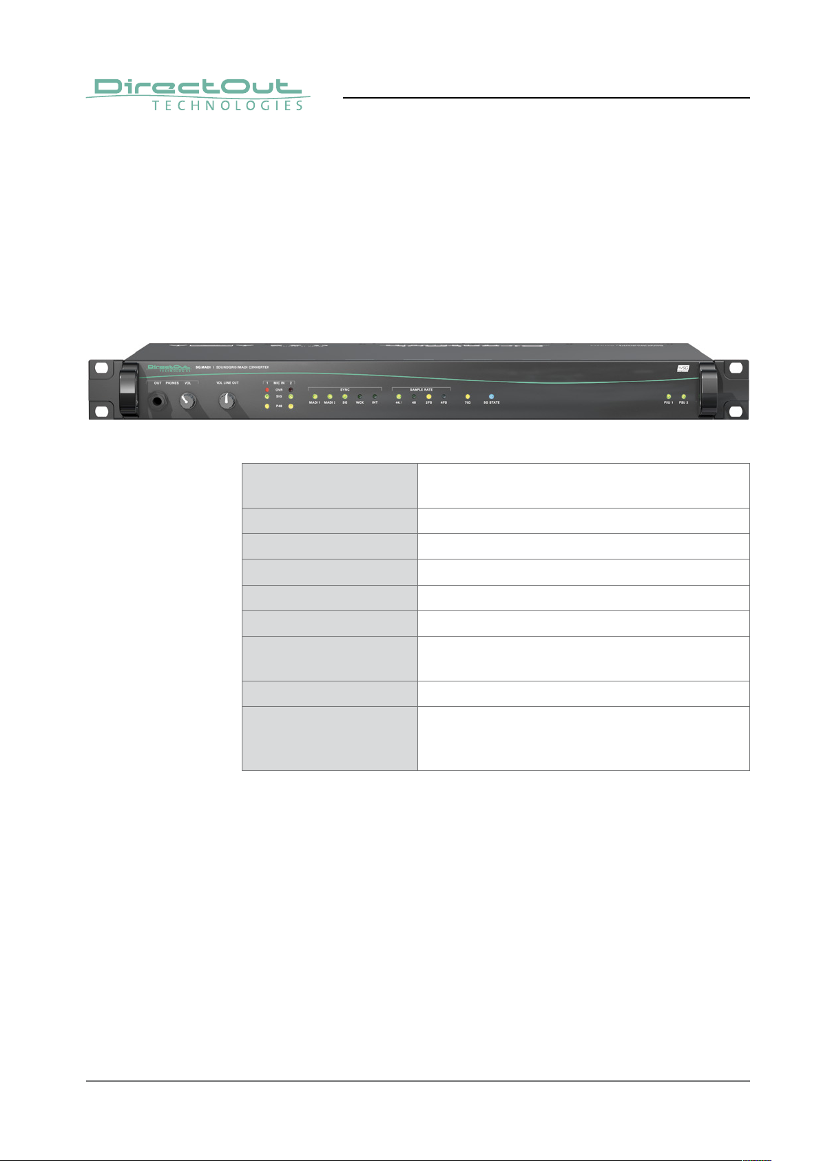
Feature Summary
MADI Ports 2 x I/O ports - individually confi gurable
with BNC coaxial, SC optical or SFP
MADI Formats 56/64 channel, 48k/96k Frame
Sample Rates 44.1, 48, 88.2, 96 kHz +/-12.5%
Network 2 x RJ45 Socket (1 Gbit/s), 128 channels (I/O)
Mic Input 2 x XLR, phantom power switchable
Line Out 2 x XLR, balanced with trim controller
Headphone Out 1 x 6.3 mm TRS jack,
unbalanced with trim controller
Audio Driver Windows® (ASIO), macOS® (Core Audio)
Power Supply This device is equipped with two wide range power
supplies (84 V to 264 V AC / 47 Hz to 63 Hz / safety
class 1)
How it works
The device is controlled via network from a computer running the SoundGrid
Studio application which is used for confi guring and patching hardware and
software I/Os on the SoundGrid network and the local SoundGrid ASIO/Core Audio
driver.
Available I/Os:
• 128 channels network audio I/O, SoundGrid
• 128 channels MADI I/O
• 2 channels analog I/O + Headphones output
page 6 of 56 SG.MADI Manual - Version 1.2
Page 7
Applications
SG.MADI meets a rich set of challenging applications:
• multi-stage venues connecting MADI and SoundGrid® consoles
• monitoring SoundGrid® and MADI signals
• inserting SoundGrid®DSP Server with Waves plug-ins into a MADI
environment
• integrating outboard equipment and DAWs to a SoundGrid® environment
• remote control of external components via SoundGrid® / MADI
CHAPTER 1: Overview
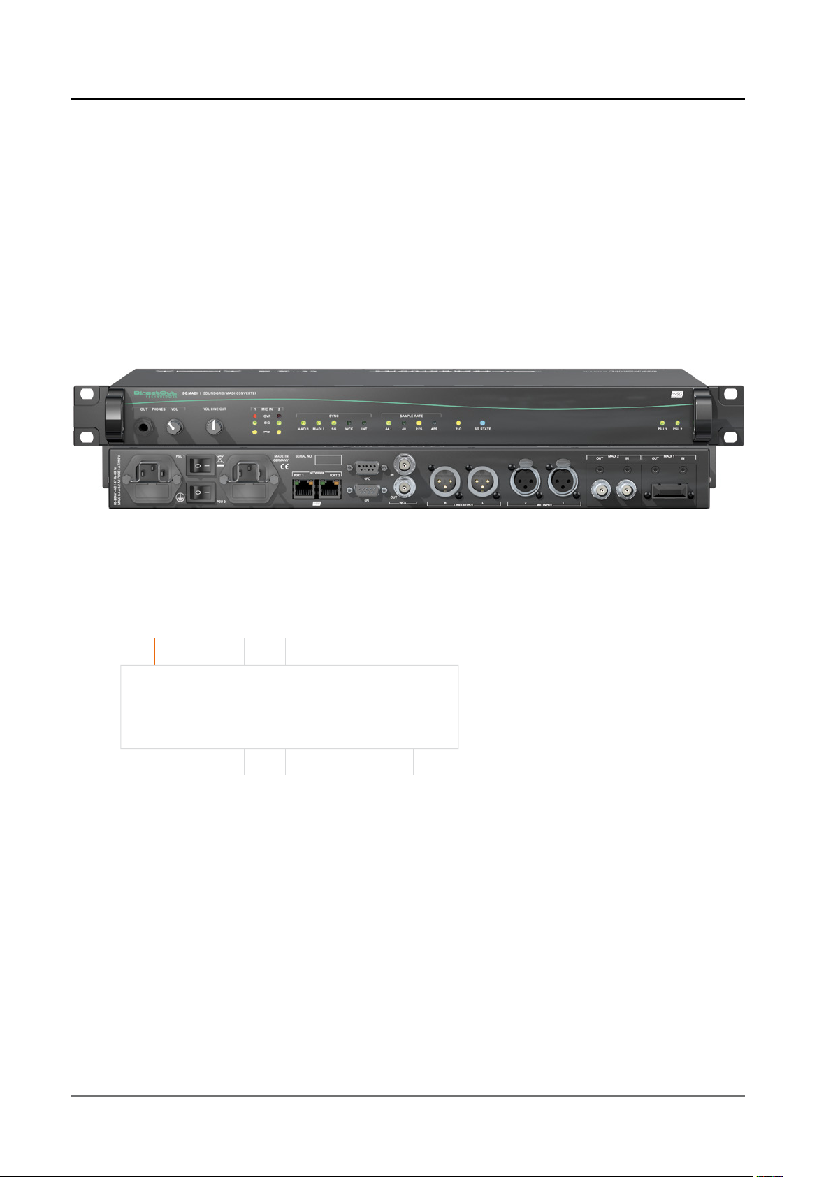
Scheme
128ch 64ch 64ch
IN/OUT
SoundGrid
MADI
OUT OUT PHONES
64ch 64ch 2ch
IN
2ch
IN
ANALOG
2ch
page 7 of 56SG.MADI Manual - Version 1.2
Page 8
CHAPTER 2: Legal issues & facts
CHAPTER 2: Legal issues & facts
Before Installing This Device
WARNING!
Please read and observe all of the following notes before installing
this product:
• Check the hardware device for transport damage.
• Any devices showing signs of mechanical damage or damage from the
spillage of liquids must not be connected to the mains supply, or
disconnected from the mains immediately by pulling out the power lead.
• All devices must be grounded. The device is grounded through its
IEC power connections.
• All devices must be connected to the mains using the three-cord power
leads supplied with the system. Only supply electrical interfaces with the
voltages and signals described in these instructions.
• Do not use the device at extreme temperatures. Proper operation can
only be guaranteed between temperatures of 5ºC and 45ºC and a
maximum relative humidity of 80%, non-condensing.
• The cabinet of the device will heat up. Do not place the device close
to heating sources (e.g. heaters). Observe the environmental conditions.
Defective Parts/Modules
WARNING!
This device contains no user-serviceable parts. Therefore do not open the device.
In the event of a hardware defect, please send the device to your DirectOut
representative together with a detailed description of the fault.
We would like to remind you to please check carefully whether the failure is
caused by erroneous configuration, operation or connection before sending parts
for repair.
page 8 of 56 SG.MADI Manual - Version 1.2
Page 9

First Aid (in case of electric shock)
WARNING!
• Do not touch the person or his/her clothing before power is turned off,
otherwise you risk sustaining an electric shock yourself.
• Separate the person as quickly as possible from the electric power source
as follows:
- Switch off the equipment.
- Unplug or disconnect the mains cable.
• Move the person away from the power source by using dry insulating
material (such as wood or plastic).
• If the person is unconscious:
- Check their pulse and reanimate if their respiration is poor.
- Lay the body down and turn it to one side. Call for a doctor immediately.
• Having sustained an electric shock, always consult a doctor.
CHAPTER 2: Legal issues & facts
page 9 of 56SG.MADI Manual - Version 1.2
Page 10
CHAPTER 2: Legal issues & facts
Updates
DirectOut products are continually in development, and therefore the information
in this manual may be superseded by new releases. To access the latest
documentation, please visit the DirectOut website:
www.directout.eu.
Intended Operation
SG.MADI is designed for conversion / routing between network audio and MADI
signals. MADI refers to AES10, network audio refers to SoundGrid® from Waves.
WARNING!
No compensation can be claimed for damages caused by operation of this unit
other than for the intended use described above. Consecutive damages are also
excluded explicitly. The general terms and conditions of business of DirectOut
GmbH are applied.
Conditions of Warranty
This unit has been designed and examined carefully by the manufacturer and
complies with actual norms and directives.
Warranty is granted by DirectOut GmbH over the period of two years for all
components that are essential for proper and intended operation of the device. The
date of purchase is applied for this period.
Consumable parts (e.g. battery) are excluded from warranty claims.
WARNING!
All claims of warranty will expire once the device has been opened or modified, or
if instructions and warnings were ignored.
For warranty claims please contact the dealer where your device was acquired.
page 10 of 56 SG.MADI Manual - Version 1.2
Page 11

CHAPTER 2: Legal issues & facts
Conformity & Certificates
CE
This device complies with the basic requests of applicable EU guidelines. The
appropriate procedure for approval has been carried out.
RoHS
(Restriction of the use of certain Hazardous Substances)
This device was constructed fulfilling the directive on the restriction of the use of
certain hazardous substances in electrical and electronic equipment 2002/95/EC.
WEEE
(Directive on Waste Electrical and Electronic Equipment)
Due to the directive 2002/96/EC for waste disposal this device must be recycled.
For correct recycling please dispatch the device to:
DirectOut GmbH,
Leipziger Str. 32
09648 Mittweida
Germany
Only stamped parcels will be accepted!
WEEE-Reg.-No. DE 64879540
Contact
DirectOut GmbH
Leipziger Str. 32, 09648 Mittweida, Germany
Phone: +49 (0)3727 5665-100
Fax: +49 (0)3727 5665-101
Mail: sales@directout.eu
www.directout.eu
page 11 of 56SG.MADI Manual - Version 1.2
Page 12

CHAPTER 2: Legal issues & facts
Contents
The contents of your SG.MADI package should include:
• 1 x SG.MADI (19’’, 1 RU)
• 2 x power chord
• 1 x fixing unit for power plug
• 1 x Manual
To complete the delivery please download from the
Waves website: www.waves.com
• Waves Central
You will need to register with a Waves account.
page 12 of 56 SG.MADI Manual - Version 1.2
Page 13

Accessory
Two different optical SFP transceiver are available from DirectOut GmbH:
• Multimode SFP transceiver with LC connectors (No: DOICT0129)
• Singlemode SFP transceiver with LC connectors (No: DOICT0130)
Specification of the optical SFP modules:
SFP Multimode Singlemode
Wavelength TX 1310 nm 1310 nm
Wavelenght RX 1310 nm 1310 nm
Distance 2 km 10 km
Powerbudget (dB) 11 dB 12 dB
Protocols Fast Ethernet OC3/STM1 Gigabit Ethernet, Gigabit
Fibre Channel
Bandwidth from 100 Mbit/s 1.050 Gbit/s
Bandwidth 155 Mbit/s 1.250 Gbit/s
CHAPTER 2: Legal issues & facts
Laser FP FP
Receiver Type PIN PIN
Connector LC LC
Wavelength TX min 1260 nm 1260 nm
Wavelength TX max 1360 nm 1360 nm
Wavelength RX min 1260 nm 1260 nm
Wavelength RX max 1620 nm 1600 nm
Transmit min - 19.00 dBm - 9.00 dBm
Transmit max - 14.00 dBm - 3.00 dBm
Receive min - 30 dBm - 21.00 dBm
Receive max
(Receiver overload)
Temperature (min) 0° Celsius 0° Celsius
Temperature (max) 70° Celsius 70° Celsius
Type of DDM/DOM internal internal
Extinction Ratio 8.20 dB 9 dB
- 5.00 dBm - 3.00 dBm
page 13 of 56SG.MADI Manual - Version 1.2
Page 14
CHAPTER 3: Installation
CHAPTER 3: Installation
Installing the Device
1. Open the packaging and check that the contents have been delivered
complete and undamaged.
2. Fix the device in a 19’’ frame with four screws, or place it on a non-slip
horizontal surface.
WARNING!
Avoid damage from condensation by waiting for the device to adapt to the
environmental temperature. Proper operation can only be guaranteed between
temperatures of 5ºC and 45ºC and a maximum relative humidity of 80%, noncondensing.
Ensure that the unit has suffi cient air circulation for cooling.
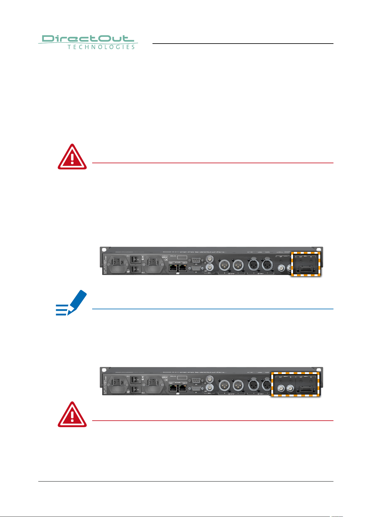
3. Remove the protective cap from the optical MADI port(s) before use.
NOTE!
Retain the protective cap if the optical port is unused. This will protect against
soiling which can lead to malfunction.
4. Connect signal cable(s) for the MADI signals.
WARNING!
All module slots must be fi tted with a module each. Otherwise live parts
become accessible which may cause serious harm to your health. An open
housing may also cause inappropriate operation conditions due to an insuffi cient
electromagnetic shielding.
page 14 of 56 SG.MADI Manual - Version 1.2
Page 15
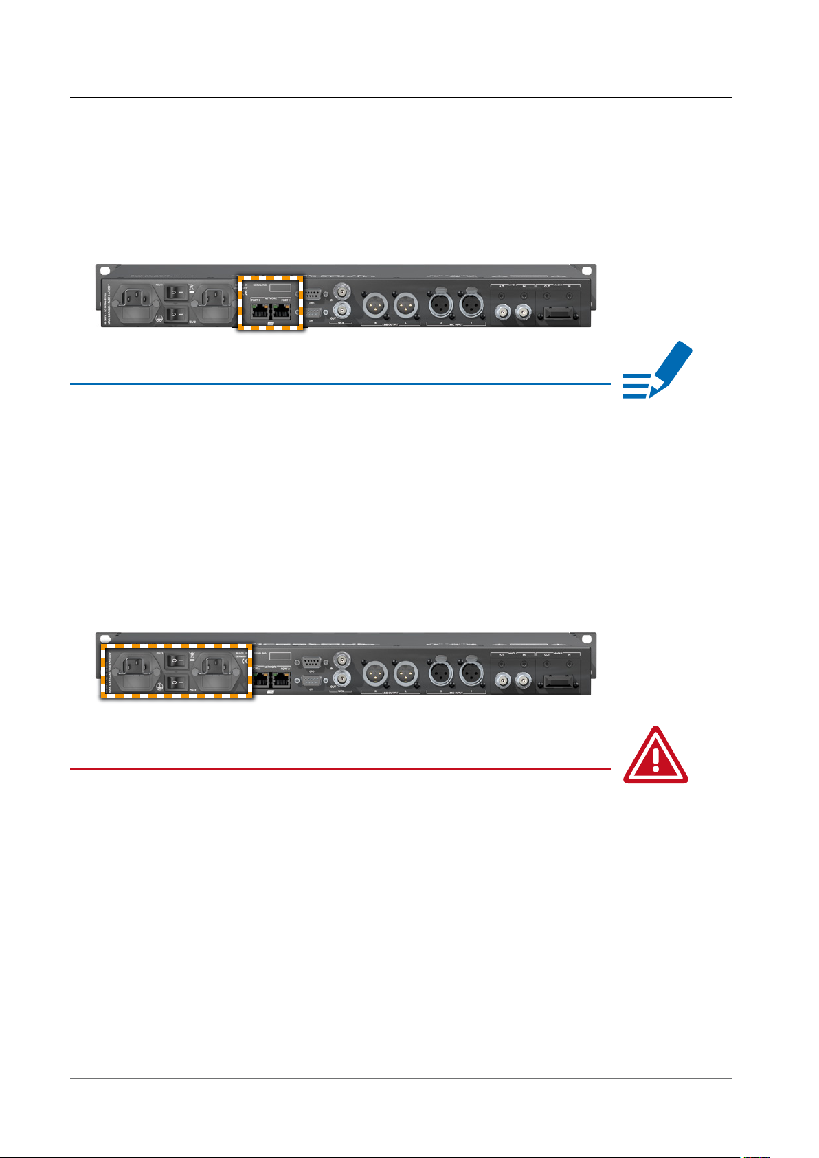
5. Plug in the network cable to the ethernet port(s) to connect the device with
your computer.
NOTE
If you are using one SG.MADI unit, connect it directly to your computer’s gigabit
ethernet port using the supplied cable.
If you are using multiple interfaces, connect them all to a SoundGrid-compatible
switch, and connect the switch to your computer’s ethernet port.
A list of approved switches is available at:
www.waves.com > Products > Hardware > SoundGrid Switches.
CHAPTER 3: Installation
6. Using the power cord provided connect the PSUs to a matching power
supply:
WARNING!
This device must be connected to the mains using the three-cord power leads
supplied with the system. Only supply the voltages and signals indicated (84 V –
264V).
7. Turn on the power switch.
page 15 of 56SG.MADI Manual - Version 1.2
Page 16

CHAPTER 3: Installation
8. Download ‘Waves Central’ for Mac or PC, as needed.
Link: www.waves.com > Downloads > Latest Version
9. Run the installer and follow the onscreen instructions when fi nished.
Launch Waves Central.
10. Click on ‘INSTALL PRODUCTS’.
page 16 of 56 SG.MADI Manual - Version 1.2
Page 17
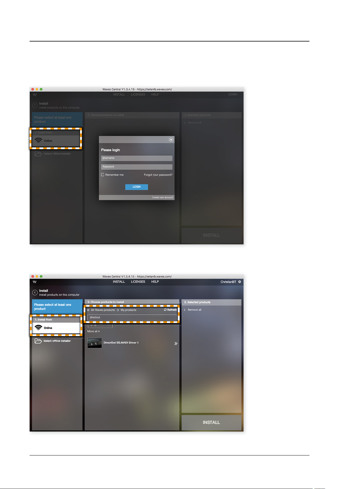
11. Select ‘Online’ in the leftmost column to install from online. The login dialog
will appear. Login with your Waves account.
CHAPTER 3: Installation
12. Search ‘All Waves products’ for ‘directout’.
page 17 of 56SG.MADI Manual - Version 1.2
Page 18

CHAPTER 3: Installation
13. Choose ‘DirectOut SG.MADI Driver 9’ to move it to the rightmost installation
column and click the button ‘INSTALL’ to start the installation process.
14. Restart your computer.
page 18 of 56 SG.MADI Manual - Version 1.2
Page 19
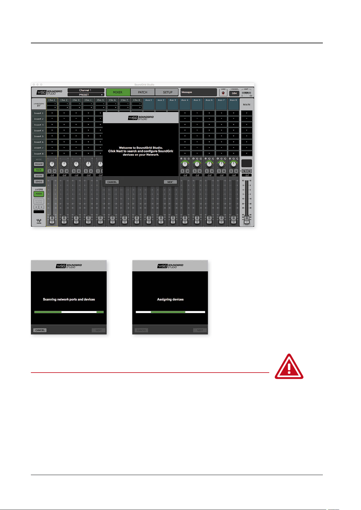
15. Launch ‘SoundGrid Studio’ and follow the instructions.
CHAPTER 3: Installation
SoundGrid Studio will scan the network for devices and update the device’s
fi rmware if necessary.
WARNING
Never disconnect any connection (network, power supply) during the fi rmware
update process. Disconnecting may lead to a defective device state which may
require to return the device to factory.
page 19 of 56SG.MADI Manual - Version 1.2
Page 20

Firmware update running.
CHAPTER 3: Installation
16. Restart the SG.MADI device after the update.
The control panel is described in „CHAPTER 5: Controlling“ on page 29.
TIP
Keep any packaging in order to protect the device should it need to be dispatched
for service.
page 20 of 56 SG.MADI Manual - Version 1.2
Page 21

CHAPTER 4: Operation
Introduction
This chapter describes the basic operation of the device.
Note that throughout this manual, the abbreviation FS refers to sample rate or
sample frequency. So, when dealing with scaling factors, the following sample
rates can be written as:
• 44.1 kHz or 48 kHz = 1 FS
• 88.2 kHz or 96 kHz = 2 FS
• 176.4 kHz or 192 kHz = 4 FS
NOTE
Scaling factor 4 FS is currently not supported by SoundGrid.
CHAPTER 4: Operation
Global Control
LEDs on the front panel indicate the power supply.
PSU 1 & 2 [rear] Switch
Enable / disable power supply.
PSU 1 & 2 [rear] 2 x C13 socket
Connect the power supply here (84 - 264 V AC).
PSU 1 & 2 [front] LED (green) - indicates state of power supply
(OFF) = power supply not working
(ON) = power supply working
(blinking) = power supply has stopped working
NOTE
The green LEDs (PSU 1 & PSU 2) indicate that a working power supply is
connected to the power supply unit. Note that an unlit LED does not guarantee
that the device is free of voltage. To ensure that the device is completely
disconnected from mains voltage, the power chords must be disconnected.
page 21 of 56SG.MADI Manual - Version 1.2
Page 22

CHAPTER 4: Operation
MADI Signals
The device is equipped with two slots each of can house one of three different i/omodules.
Available are:
• SC optical multi-mode or single-mode
• BNC coaxial, 75 Ω
• SFP (without module - see„Accessory“ on page 13)
MADI 1
OUT / IN
MADI 2
OUT / IN
* confi guration example
Modules
SC module BNC module SFP module
Single-Mode / Multi-Mode
The SC ports are multi-mode as default. It is possible to equip the device with
single-mode SC ports. The housing of single-mode ports is colored blue.
2 x SC socket (optical)*
O U T:
MADI output, connect for MADI output signal here.
MADI input, connect MADI input signal here.
IN:
2 x BNC socket (coaxial)*
MADI output, connect for MADI output signal here.
O U T:
IN: MADI input, connect MADI input signal here.
multi-mode single-mode
page 22 of 56 SG.MADI Manual - Version 1.2
Page 23

Analog Signals
Two analog I/Os and a headphones output are available. The line output and the
headphones output feature a level trim controller at the front. For the analog inputs
there is a led display monitoring input level and status of phantom power.
CHAPTER 4: Operation
MIC INPUT
1 & 2
LINE OUTPUT
1 & 2
PHONES
OUT
PHONES
VOL
VOL LINE OUT 1 x Potentiometer for volume control
MIC IN (1 & 2)
OVR
MIC IN (1 & 2)
SIG
2 x XLR female, balanced*
Connect analog input signal here.
2 x XLR male, balanced
Connect for analog output signal here.
1 x TRS jack 6.3 mm (stereo)
Connect for headphones output signal here.
1 x Potentiometer for volume control
of headphones output**
Turn the knob to adjust the volume.
of line output**
Turn the knob to adjust the volume.
LED (red): indicates an analog input overload.
(ON) = analog input signal equals to more
than -1 dBFS
LED (green): indicates signallevel of channel
input.
(ON) = analog input signal equals to more
than -80 dBFS. The light intensity of the LED
depends on the audio level.
MIC IN (1 & 2)
P48
* Phantom power (48 V) and gain control are accessible in the remote control.
The input sensitivity ranges from - 56 to + 24 dBu, corresponding a gain range
from 0 to 80 dB, which is adjustable in 1 dB steps.
** Both a fader in the remote control and the potentiometer affect the level
- see page 38. The setting of the potentiometer is not refl ected in the remote
control.
LED (yellow): indicates activation status of
phantom power
(OFF) = phantom power not active
(ON) = phantom power active
page 23 of 56SG.MADI Manual - Version 1.2
Page 24

CHAPTER 4: Operation
Network
Two gigabit-ethernet ports are used for transmission of network audio and to
control the device. Firmware updates also use the network connection.
NETWORK
Port 1
NETWORK
Port 2
NETWORK
LED left (Port 1 & 2)
NETWORK
LED right (Port 1 & 2)
* Some possible reasons that lead to an inactive link:
• device switched off
• connected device switched off
• cabling issue
RJ 45 socket
Connect here for network transmission.
RJ 45 socket
Connect here for network transmission.
LED orange - indicates the link state of the
network connection*.
(ON) = device link active
(OFF) = device link not active
LED green - indicates the activity state of
the network connection.
(ON) = data sent or received
(OFF) = no data transmission
NOTE
For correct operation of the SoundGrid network a dedicated network card
supporting 1 Gbit/s is required on your computer.
page 24 of 56 SG.MADI Manual - Version 1.2
Page 25

Clocking
The device offers several options for clocking.
• MADI input
• SoundGrid (SoE)
• Word Clock
• Internal clock generator
CHAPTER 4: Operation
WCK
OUT / IN
The front panel informs about selected clock sources and their lock / sync state.
SYNC
MADI (Port 1 & 2)
SG
WCK
INT
2 x BNC socket (coaxial), 75 Ω
OUT = word clock output, connect here
for word clock output signal (AES11)
IN = word clock input,
connect word clock signal (AES11) here.
LED green - indicates the lock / sync state of
MADI input, SoundGrid, word clock or the
internal clock generator.
(OFF) = no signal lock
(ON) = signal lock, in sync
(blinking) = signal lock, not in sync with selected
clock source
or
input selected as clock source and
no signal lock.
page 25 of 56SG.MADI Manual - Version 1.2
Page 26
CHAPTER 4: Operation
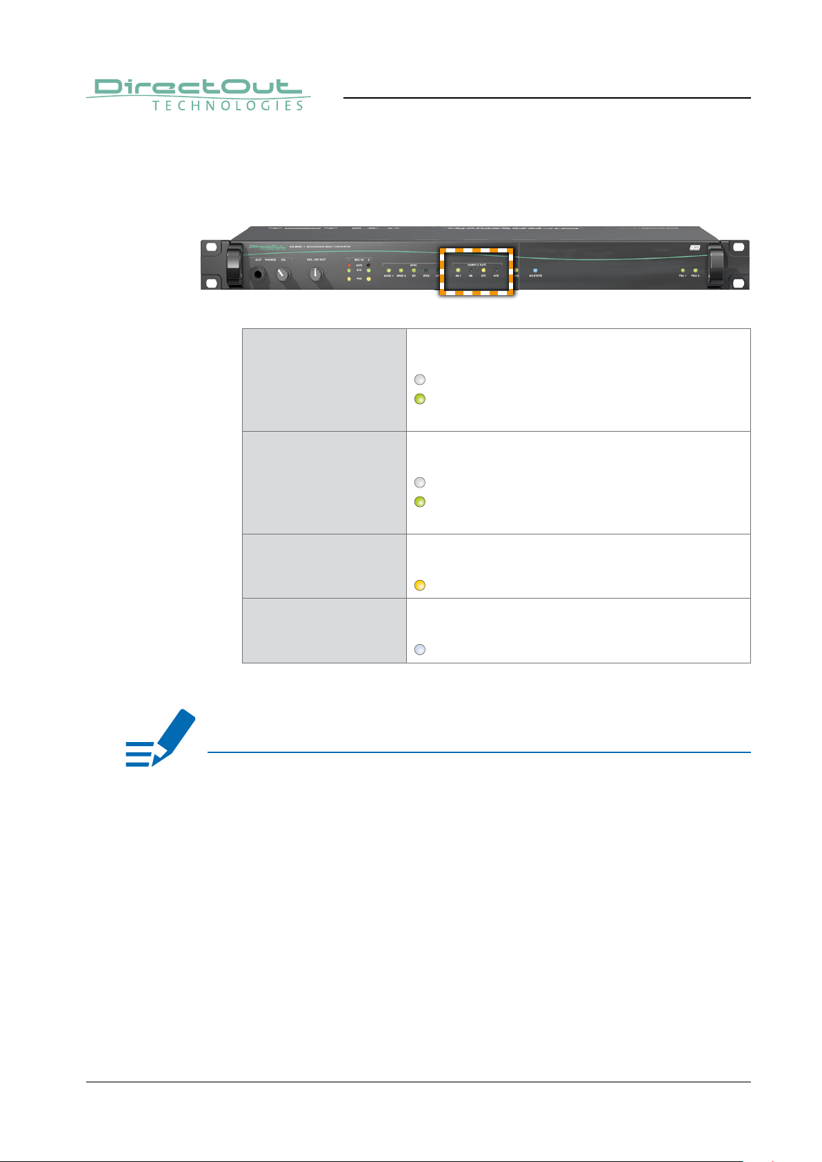
Sample Rate
The base rate (44.1 kHz, 48 kHz) and the scaling factor (1 FS, 2 FS, 4 FS) is
displayed by four leds at the front panel.
SAMPLE RATE
44.1k
SAMPLE RATE
48k
SAMPLE RATE
2 FS
SAMPLE RATE
4 FS
* If both LED 2 FS and 4 FS are off, the scaling factor is 1 FS.
LED (green) - indicates the base rate of the
audio engine.
(OFF) = base rate is different from 44.1 kHz
(ON) = base rate of 44.1 kHz (or multiple of)
is used
LED (green) - indicates the base rate of the
audio engine.
(OFF) = base rate is different from 48 kHz
(ON) = base rate of 48 kHz (or multiple of)
is used
LED (yellow) - indicates the scaling factor of
the base rate.*
(ON) = scaling factor is 2 FS
LED (white) - indicates the scaling factor of
the base rate.*
(ON) = scaling factor is 4 FS
NOTE
At higher sample rates the number of audio channels of a single MADI stream is
reduced depending on the integer of the scaling factor:
• 64 channels at 1 FS
• 32 channels at 2 FS
• 16 channels at 4 FS
Scaling factor 4 FS is currently not supported by SoundGrid.
page 26 of 56 SG.MADI Manual - Version 1.2
Page 27

Termination
The coaxial connection of the word clock can be terminated with 75Ω to match
the impedance according the wiring. It shall be activated if the signal is not daisy
chained to another device.
75 Ω LED (yellow) - indicates the activation state
of 75 Ω termination of the word clock input.
(OFF) = input not terminated
(ON) = input terminated with 75 Ω
CHAPTER 4: Operation
SG State
The status of the SoundGrid network card is monitored by a LED at the front.
SG STATE LED (RGB) - indicates the state of the
SoundGrid card.
(ON, blue) = normal operation, all ok
(blinking, red) = no SG host connected or
network cable not connected
(ON, yellow) = fi rmware update in progress
(various colors) = identifi cation
page 27 of 56SG.MADI Manual - Version 1.2
Page 28

CHAPTER 4: Operation
GPI / GPO
Two GPIs and two GPOs are available via DSUB-9 connectors
Each GPI (General Purpose Input) can be triggered by connecting the input pin with
ground (GND) or by a voltage source between input pin and ground. The high level
of the voltage may range between 2 V and 24 V due to a safety limiter in the input.
Each GPO (General Purpose Output) uses a low resistance (FET) switch to ground
(GND). It can handle an external voltage source between 0V and 24V.
A 5 V local voltage source can also be used for signalling purposes. Its output is
current-limited to 200 mA.
GPI DSUB-9 socket (female)
Connect for two GPIs.
Pinout:
see „Appendix A - Wiring Sketches“ on page 52
GPO DSUB-9 socket (female)
Connect for two GPOs.
Pinout:
see „Appendix A - Wiring Sketches“ on page 52
page 28 of 56 SG.MADI Manual - Version 1.2
Page 29
CHAPTER 5: Controlling
SoundGrid host
The remote control of SG.MADI requires a SoundGrid host application such as
SoundGrid Studio, MultiRack SoundGrid or eMotion LV1 being installed. From here
the control panel for SG.MADI can be launched.
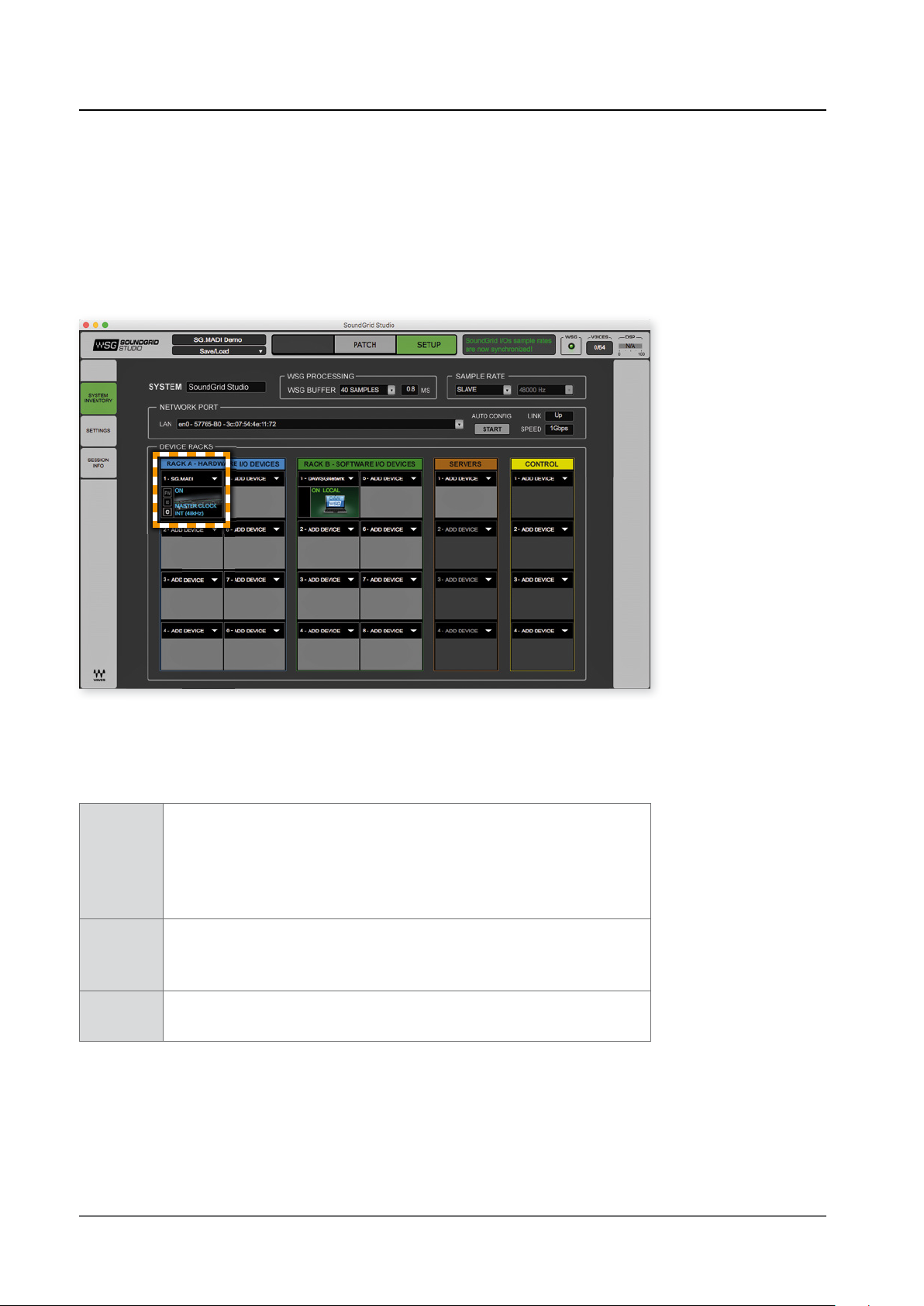
CHAPTER 5: Controlling
SoundGrid Studio in setup mode showing SG.MADI in the device rack of the
system inventory.
Next to the device there are three buttons:
FW Indicates the status of the device’s fi rmware
grey = fi rmware compatible
blue = fi rmware compatible, but newer version exists
red = fi rmware not compatible and must be updated
in order to use.
ID Button.
Click to show a rainbow pattern on the LED ‘SG STATE’ at the front
panel.
Control
wheel
Button
Click to open the control panel for SG.MADI
page 29 of 56SG.MADI Manual - Version 1.2
Page 30

CHAPTER 5: Controlling
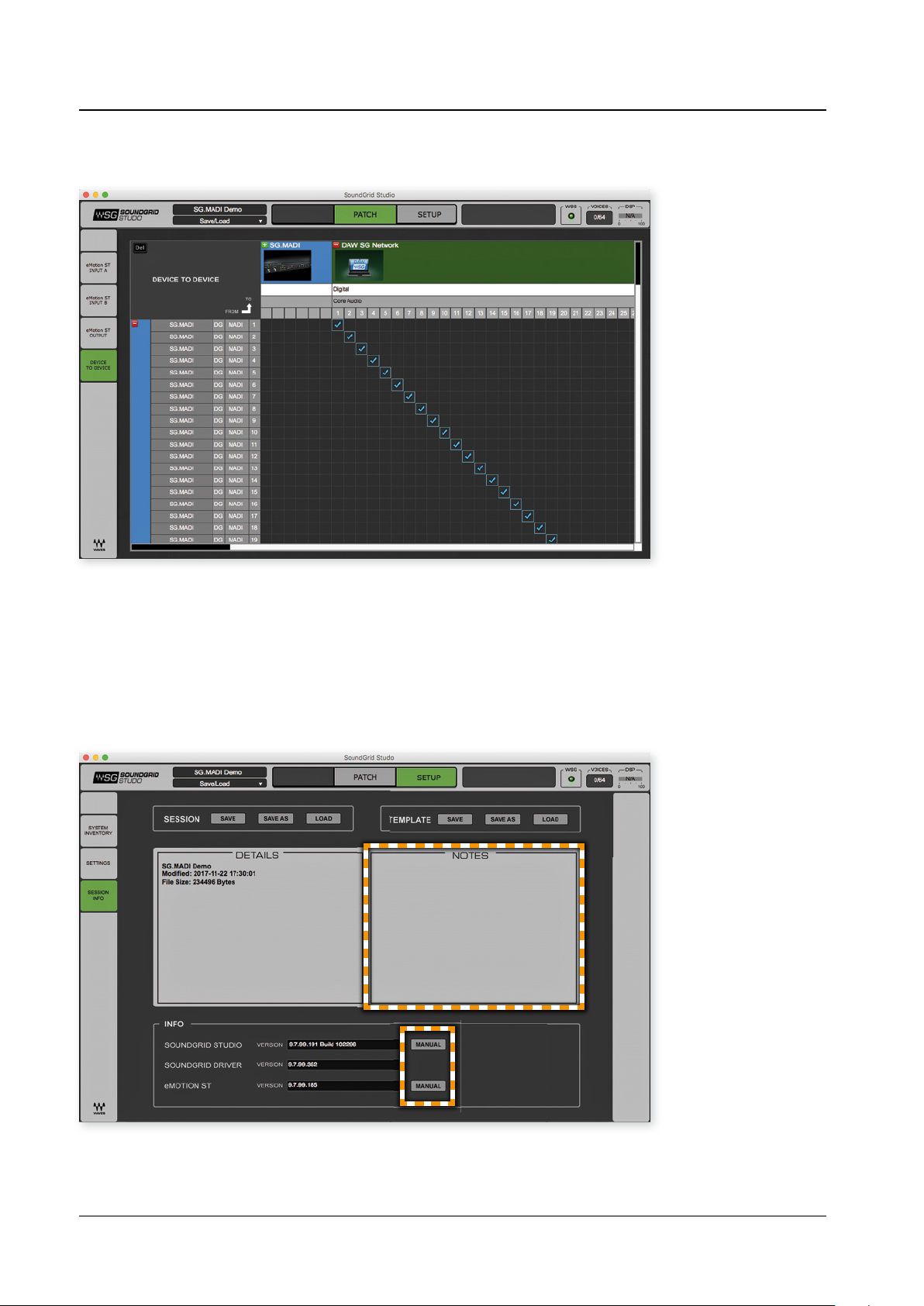
Signal Routing
To setup your signal routing between devices open the tab ‚PATCH‘ and switch to
the routing matrix ‚DEVICE TO DEVICE. With SG.MADI connected you should see
two MADI I/Os and 128 channels of SoundGrid.
Matrix in collapsed view. ‘SG.MADI’ are the two MADI I/Os of SG.MADI.
‘DAW SG Network’ is the SoundGrid Network (Core Audio driver).
• Inputs are arranged vertically, outputs are arranged horizontally.
• The name of the devices can be modifi ed, double click the name to edit.
• If there is no signal detected at a MADI input the matrix will show
56 input channels.
• The patches can be saved / restored to / from a fi le via the button ‚Save/Load‘.
• Signal Routing for the analog I/Os is accessible in the tab ‘SETUP’ of the
SG.MADI control panel - see page 38 or page 40.
• The number of SoundGrid Driver channels is adjustable in the system
inventory (setup mode).
page 30 of 56 SG.MADI Manual - Version 1.2
Page 31
CHAPTER 5: Controlling
Matrix in expanded view. Example: 1:1 patch MADI input to SoundGrid network.
Session Info
The tab ‘SESSION INFO’ in the section ‘SETUP’ can be used to add notes to a
routing session. Further it offers a links to further information around SoundGrid
Studio and eMotion ST.
page 31 of 56SG.MADI Manual - Version 1.2
Page 32

SG.MADI Control
The control panel is organized into different tabs:
• ABOUT = device overview
• SYSTEM = hardware related information
• CLOCK = clock settings and status info for SG.MADI
• INPUT = level display for the analog and MADI inputs
• OUTPUT = level display for the analog and MADI outputs
• SETUP = device control (level, phantom power, GPO…)
To navigate click on the corresponding button at the bottom.
CHAPTER 5: Controlling
Tab ‘ABOUT’ displaying the device information.
LOAD Button
Click to load a stored session.
SAVE Button
Click to restore a session from fi le.
Demo...
ID Button
page 32 of 56 SG.MADI Manual - Version 1.2
Text fi eld displaying the name fo the current session.
Click to edit the name
Click to show a rainbow pattern on the LED ‘SG STATE’ at the front
panel.
Page 33

CHAPTER 5: Controlling
Tab ‘SYSTEM’ displaying hardware related information.
You may need this information for support incidents.
page 33 of 56SG.MADI Manual - Version 1.2
Page 34

CHAPTER 5: Controlling
Clocking
SG.MADI can be clocked to various sources:
• MADI input 1 or 2
• Word clock
• SoE (Sync over Ethernet)
• Internal clock generator
At the same time the device may act as SoE master to provide clock information to
for other network devices.
SOURCE
upper
Drop-down menu to select clock source type.
Click to select from the list.
Values: Internal, External word clock, Digital, SoE*
SOURCE
lower
Drop-down menu to select the signal source.
Click to select from the list.
Values: MADI Port 1, MADI Port 2
SAMPLE RATE Drop-down menu to defi ne the sample rate.**
Click to select from the list.
Values: 44.1 / 48 / 88.2 / 96 kHz
* SoE becomes available when a SoE master is detected in the network.
Device can’t be SoE master and SoE slave at the same time.
** When clocking to Digital or Word Clock the base rate is defi ned.
So the menu is used only to adjust the correct scaling factor
(44.1 / 48 kHz = 1 FS < > 88.2 / 96 kHz = 2 FS) - see page 21.
page 34 of 56 SG.MADI Manual - Version 1.2
Page 35

STAT US Display
Reports the presence or absence of sync between
SG.MADI and the SoundGrid network.
SOE Display
Indicates whether SG.MADI is master or a slave in the
SoundGrid network.
CHAPTER 5: Controlling
CURRENT
CLOCK
SOURCE
Display
Displays the current sync method. If the selected clock
source is lost, the fallback source is displayed in red letters
instead.*
WORD CLOCK
TERMINATION
STAT US
MADI 1 / 2
WORD CLOCK
Button to adjust word clock termination status.**
Click to toggle termination state between ON and OFF.
Display to monitor input signal status.
Sync = input signal detected, in sync with current
clock source
Lock = input signal detected, not in sync with current
clock source
No lock = no valid input signal detected
* Fallback sequence: the system clock will switch to internal, if the selected
clock source (Digital or Word Clock or SoE) fails.
** Termination shall be activated if the signal is not daisy chained to another
device.
page 35 of 56SG.MADI Manual - Version 1.2
Page 36

CHAPTER 5: Controlling
Level Display
Two tabs show a channel based level display of the analog and MADI inputs and
outputs.
page 36 of 56 SG.MADI Manual - Version 1.2
Page 37

MIC 1 / MIC 2 Level display*
Monitoring the level of the two analog inputs (XLR jack) at
the rear panel of the device.
LINE OUT Level display*
Monitoring the level of the two analog outputs (XLR jack) at
the rear panel of the device.
CHAPTER 5: Controlling
MADI 1 INPUT
MADI 2 INPUT
Level display
Monitoring the level of each MADI input channel individually.
LED red = -1 dBFS = level > -1 dBFS
LED yellow = -10 dBFS < level < -1 dBFS
LED green = -40 dBFS < level < -10 dBFS
MADI 1 OUTPUT
MADI 2 OUTPUT
Level display
Monitoring the level of each MADI output channel
individually.
LED red = -1 dBFS = level > -1 dBFS
LED yellow = -10 dBFS < level < -1 dBFS
LED green = -40 dBFS < level < -10 dBFS
* The level display is located post faders. Check the level setting of both the
fader in the remote control and the potentiometer at the front panel.
page 37 of 56SG.MADI Manual - Version 1.2
Page 38
CHAPTER 5: Controlling
Setup
The tab SETUP provides access to the device functions of SG.MADI:
• Level / volume control of the analog I/Os
• Monitoring output source (phones / line out)
• Mic / line inputs routing
• Control of GPOs
• MADI output source and format
• MADI input status display
• Fan control
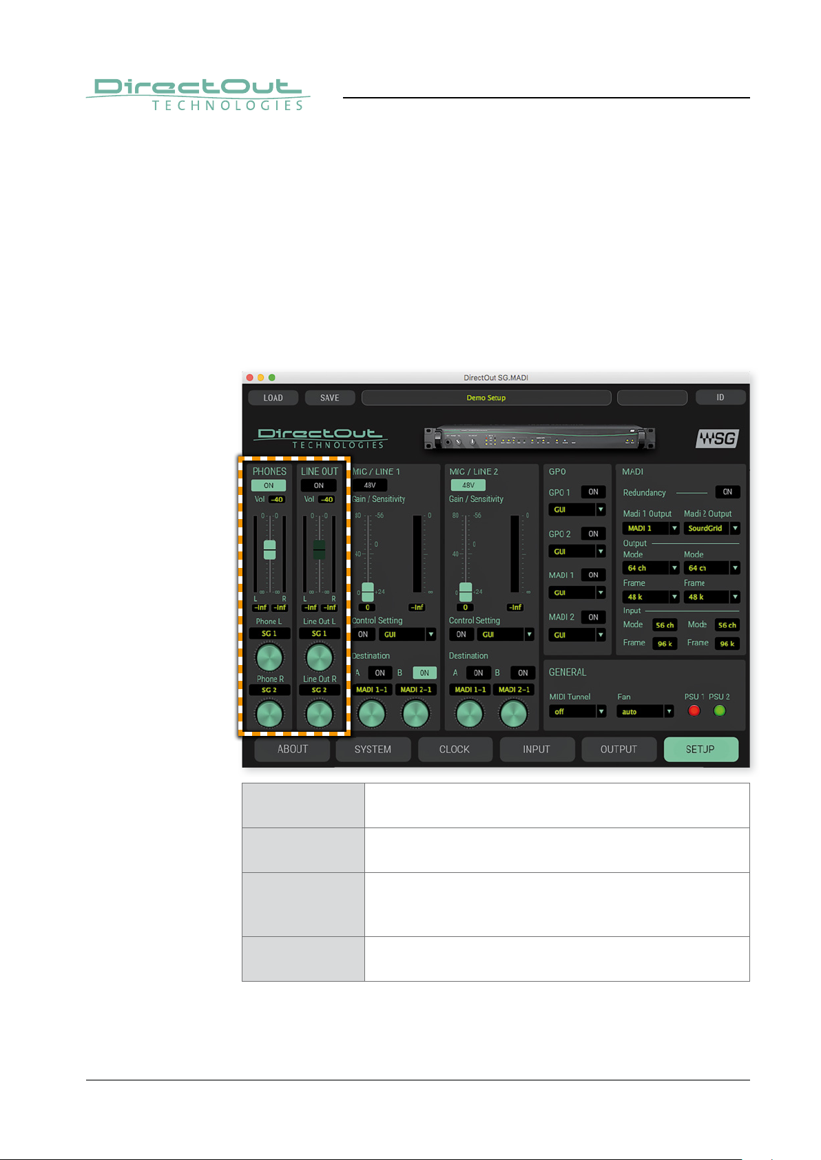
Analog Outputs
PHONES
ON
Button
Click to toggle the phones output between ON and OFF.
PHONES Fader*
Click and move to adjust volume level of phones output.
PHONES
Vol
Display
Indicates the numeric value of adjusted volume.
Range: -90 to 0 dB in 1 dB steps
PHONES
bargraph/fi eld
page 38 of 56 SG.MADI Manual - Version 1.2
Level Display**
Indicates the current signal level feeding the phones output.
Page 39

CHAPTER 5: Controlling
PHONES
rotary knobs
Drop-down menu to select the signal source.***
Click, hold and move to select the signal source individually
for the left and right channel of the phones output.
Values:
MADI 1-1 to MADI 1-64,
MADI 2-1 to MADI 2-64
PHONES
field
LINE OUT
ON
LINE OUT Fader*
LINE OUT
Vol
LINE OUT
bargraph/field
LINE OUT
rotary knobs
Display
Indicates the selected source for the phones output.
Button
Click to toggle the phones output between ON and OFF.
Click and move to adjust volume level of line output.
Display
Indicates the numeric value of adjusted volume.
Range: -90 to 0 dB in 1 dB steps
Level Display**
Indicates the current signal level feeding the line output.
Drop-down menu to select the signal source.***
Click, hold and move to select the signal source individually
for the left and right channel of the line output.
Values:
MADI 1-1 to MADI 1-64,
MADI 2-1 to MADI 2-64
SG 1 to 128,
SG 1 to 128,
LINE OUT
field
* Both the fader in the remote control and the potentiometer at the front
panel affect the level - see page 23.
** The level display is located post faders. Check the level setting of both the
fader in the remote control and the potentiometer at the front panel.
*** SG 1 - 128 = SoundGrid network, channel 1 to 128
MADI 1-1 to MADI 1-64 = MADI 1 input, channel 1 to 64
MADI 2-1 to MADI 2-64 = MADI 2 input, channel 1 to 64
Display
Indicates the selected source for the line output.
page 39 of 56SG.MADI Manual - Version 1.2
Page 40

Analog Inputs
CHAPTER 5: Controlling
The controls for Mic / Line 1 and Mic / Line 2 are identical.
Each input can be assigned to two different destinations (A / B).
Mic / Line
48V
Gain / Sensitivity Fader
Button
Click to toggle phantom power between ON (green) and
OFF (black).
Click and move to adjust signal gain for the mic / line input.
Range:
0 to 80 dB in 1 dB steps
(corresponding input sensitivity +24 dBu to -56 dBu)
Gain / Sensitivity
fi eld
Gain / Sensitivity
bargraph/fi eld
Display
Indicates the numeric value of adjusted gain.
Level Display
Indicates the current input signal level of mic / line input.
page 40 of 56 SG.MADI Manual - Version 1.2
Page 41

CHAPTER 5: Controlling
Control Setting
ON
Control Setting Drop-down menu to define which source controls
Destination A / BONButton
Destination A / B
rotary knobs
Button / Display
Click to toggle mic / line input between ON (green) and OFF
(black).
Button function is available only with Control Setting ‘GUI’.
If the Control Setting is not ‘GUI’, the button only serves to
display the ON / OFF status.
ON / OFF state.*
Click to select the method for switching between ON and
OFF.
Values: GPI 1, GPI 2, MADI 1, MADI 2,
GPI 1 inv., GPI 2 inv., MADI 1 inv., MADI 2 inv., GUI
Click to toggle signal output to destination between ON
(green) and OFF (black).
Drop-down menu to select the signal source.**
Click, hold and move to select the signal source for
destination A or B.
Values:
SG 1 to 128,
MADI 1-1 to MADI 1-64,
MADI 2-1 to MADI 2-64
Destination A / B
field
* GPI 1/2 = GPI input 1/2
MADI 1/2 = MADI 1 / 2 input signal (embedded control data)
GPI 1/2 inv. = same as GPI 1 / 2, but inverted behavior
MADI 1/2 inv. = same as MADI 1 / 2, but inverted behavior
GUI = control panel
** SG 1 - 128 = SoundGrid network, channel 1 to 128
MADI 1-1 to MADI 1-64 = MADI 1 input, channel 1 to 64
MADI 2-1 to MADI 2-64 = MADI 2 input, channel 1 to 64
Display
Indicates the selected destination for the mic / line input
signal.
NOTE
The output routing of destination A and B will override the MADI output routing on
the particular channels.
page 41 of 56SG.MADI Manual - Version 1.2
Page 42
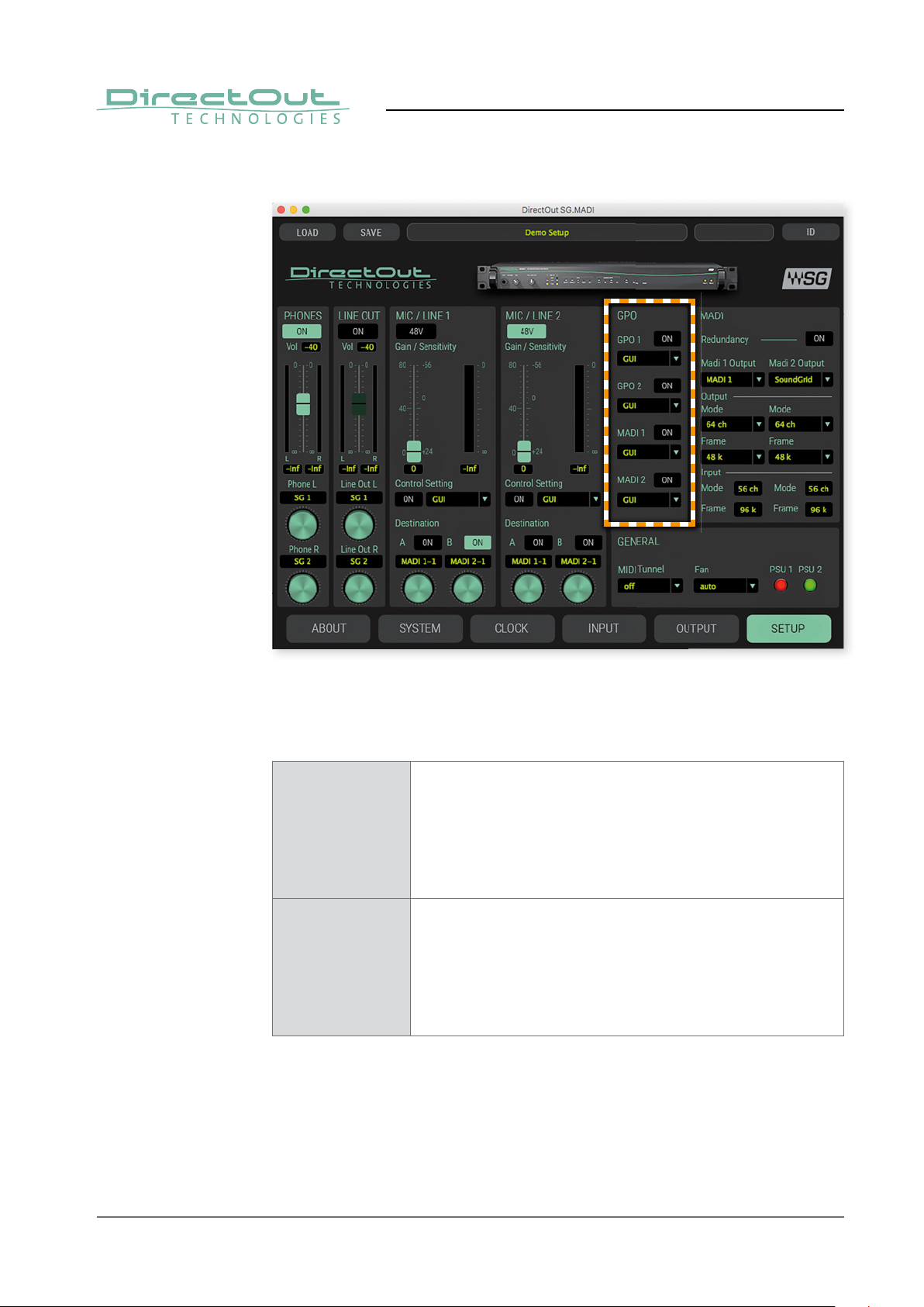
GPO
CHAPTER 5: Controlling
SG.MADI provides two physical GPOs (GPO 1/2) that may be triggered by various
sources. Further a separate GPO control signal may be embedded into the MADI
output signal - individually for each MADI output (MADI 1/2).
GPO 1/2
ON
Button / Display
Click to toggle GPO 1/2 between ON (green) and OFF
(black).
Button function is available only with Control Setting ‘GUI’.
If the Control Setting is not ‘GUI’, the button only serves to
display the ON / OFF status.
GPO 1/2 Drop-down menu to defi ne which source controls
ON / OFF state.*
Click to select the method for switching between ON and
OFF.
Values: GPI 1, GPI 2, MADI 1, MADI 2,
GPI 1 inv., GPI 2 inv., MADI 1 inv., MADI 2 inv., GUI
page 42 of 56 SG.MADI Manual - Version 1.2
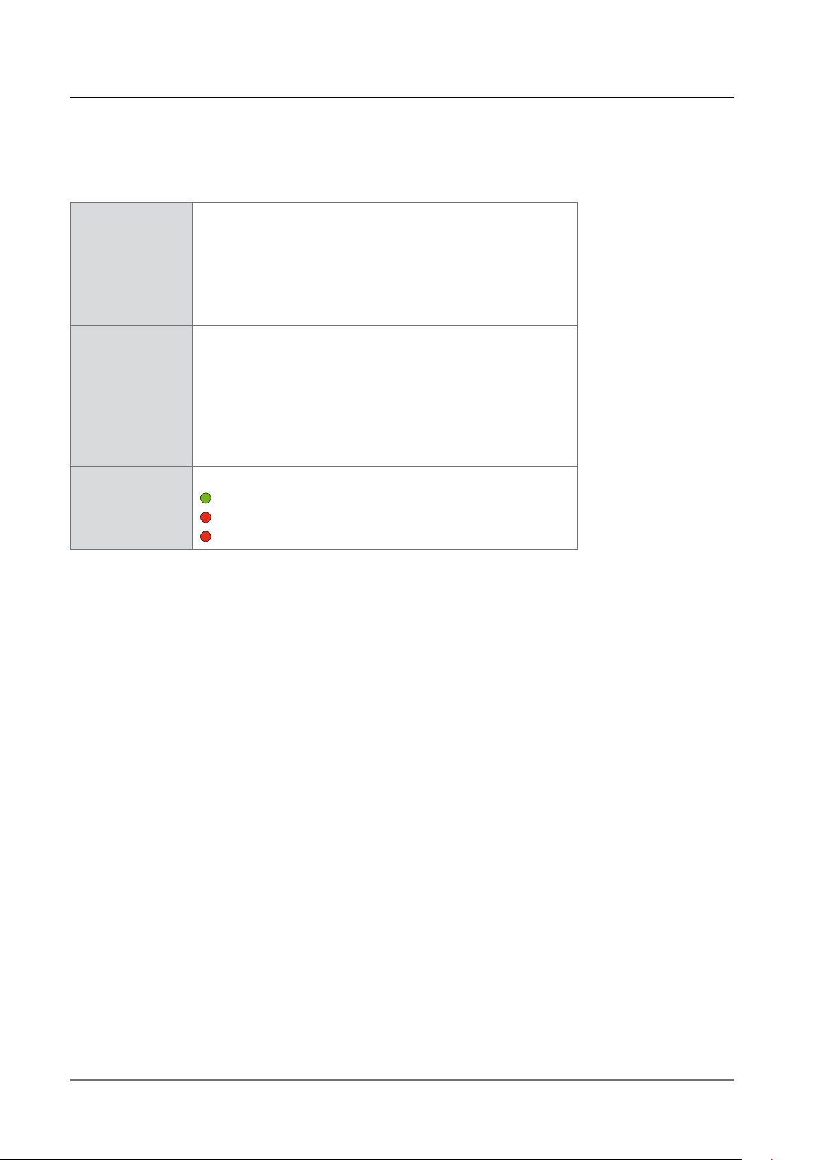
Page 43

CHAPTER 5: Controlling
MADI 1/2
ON
Button / Display
Click to toggle GPO via MADI 1/2 between ON (green) and
OFF (grey).
Button function is available only with Control Setting ‘GUI’.
If the Control Setting is not ‘GUI’, the button only serves to
display the ON / OFF status.
MADI 1/2 Drop-down menu to define which source controls
ON / OFF state.*
Click to select the method for switching between ON and
OFF.
Values: GPI 1, GPI 2, MADI 1, MADI 2,
GPI 1 inv., GPI 2 inv., MADI 1 inv., MADI 2 inv., GUI
* GPI 1/2 = GPI input 1/2
MADI 1/2 = MADI 1 / 2 input signal (embedded control data)
GPI 1/2 inv. = same as GPI 1 / 2, but inverted behavior
MADI 1/2 inv. = same as MADI 1 / 2, but inverted behavior
GUI = control panel
page 43 of 56SG.MADI Manual - Version 1.2
Page 44

MADI Input / Output
CHAPTER 5: Controlling
SG.MADI is equipped with two module based MADI ports. Each MADI output may
be assigned to three different sources:
• MADI 1
• MADI 2
• SoundGrid
Channel based routing is set in the tab ‚PATCH‘, page ‚DEVICE TO DEVICE’ - see
page 30.
The signal format (channel mode / frame format) of the outputs can be confi gured
for each port individually. The format of the input signal is displayed separately
below.
The two MADI inputs may be confi gured as redundant. Activated redundancy
implies:
• only one MADI input is used (initial priority MADI 1)
• both MADI outputs are carrying identical signals
• strip for MADI 2 output becomes inactive
• MADI 1 output source: Setting ‘MADI 1‘ or ‚MADI 2‘ will fed the particular
MADI input that is selected by the redundancy mechanism (ignoring the
numbering).
page 44 of 56 SG.MADI Manual - Version 1.2
Page 45

The controls for MADI 1 Output and MADI 2 Output are identical.
CHAPTER 5: Controlling
Redundancy
ON
MADI 1 Output Drop-down menu to select the source for MADI 1
Mode Drop-down menu to select the channel mode for
Frame Drop-down menu to select the frame format for
Mode Display
Input Frame Display
Button
Click to toggle MADI input redundancy between ON (green)
and OFF (black).
output.*
Click to select.
Values: MADI 1, MADI 2, SoundGrid
MADI 1 output signal.
Click to select.
Values: 56 ch, 64 ch (28 ch, 32 ch @ 2 FS)
MADI 1 output signal.
Click to select.
Values: 48 k, 96 k (96k Frame is active @ 2 FS only)
Monitors the detected channel mode of MADI input signal.
Values: 56 ch, 64 ch (28 ch, 32 ch @ 2 FS)
Monitors the detected frame mode of MADI input signal.
Values: 48 k, 96 k
* Selecting either MADI input will result in 1:1 patching which cannot be altered
in the matrix (‘PATCH’ / ‘Device to Device’).
NOTE
The output routing of destination A and B (Analog Inputs - page 40) will override
the MADI output routing on the particular channels.
page 45 of 56SG.MADI Manual - Version 1.2
Page 46

General
CHAPTER 5: Controlling
MIDI Tunnel enables to transport control data via a MADI link. For example an
ANDIAMO.MC may be remote controlled from the connected SG host via MIDI
data that is embedded into the MADI link. A closed loop between MADI input,
remote device and MADI output is required for proper operation.
Fan control offers the possibility to adapt the fan speed / noise to the
environmental conditions.
Two LEDs inform about the status of the power supplies.
page 46 of 56 SG.MADI Manual - Version 1.2
Page 47
MIDI Tunnel* Drop-down menu to select the MADI link for
transport of control data.
Click to select.
off = no de-/embedder active
MADI 1 = de-/embedder activ on MADI port 1
MADI 2 = de-/embedder activ on MADI port 2
Fan Drop-down menu to select the behaviour of the
fan control.
Click to select.
auto = fan speed is controlled by the temperature sensor
slow = fan always on, at slow speed
mid = fan always on, at mid speed
high = fan always on, at high speed
CHAPTER 5: Controlling
PSU
[1 / 2]
LEDs to monitor the status of the power supply.
LED green = power supply on
LED red = power supply off
LED red (blinking) = power supply off after on
* MIDI Tunnel is currently not supported.
page 47 of 56SG.MADI Manual - Version 1.2
Page 48

CHAPTER 6: Troubleshooting and Maintenance
CHAPTER 6: Troubleshooting and Maintenance
Troubleshooting
To identify a possible defect with the device please consult the following table.
If the fault cannot be resolved using these instructions, please contact your local
DirectOut representative or visit support.directout.eu.
Waves support: https://www.waves.com/support
Issue Possible reason Solution
Device doesn’t
work.
Optical port does
not work.
No signal at the
output port.
No signal at the
output port.
MADI signal at the
input is not stable.
Power supply is
broken.
Optic is dirty. Use an air supply to carefully remove any
Connections (input /
output) are mixed up.
Signal cable defective. Exchange the signal cable.
Signal source is
defective
or
bad signal condition
(Jitter > 1 ns) - e.g.
due to exceeded
length or bad
screening attenuation
of signal cable.
Check that the power supply switch
is on, that the device is connected to
the power supply and that the socket
is working. Defective fuses must be
exchanged by qualified service personal
only.
dust.
Never use objects for cleaning.
Check the connections and change the
cables if necessary.
Check the routing matrix.
Change the source
or
use appropriate cables.
No signal at the
analog outputs.
page 48 of 56 SG.MADI Manual - Version 1.2
Source not patched
or
channel strip switched
off
or
level setting of either
gui or potentiometer
off.
Check signal routing
or
check the on/off state of channel strip
or
check fader in the gui and potentiometer
at the front panel.
Page 49

CHAPTER 6: Troubleshooting and Maintenance
Maintenance
To clean the device, use a soft, dry cloth. To protect the surface, avoid using
cleaning agents.
NOTE!
The device should be disconnected from the power supply during the cleaning
process.
page 49 of 56SG.MADI Manual - Version 1.2
Page 50

CHAPTER 7: Technical Data
Dimensions
• Width 19’’ (483 mm)
• Height 1 RU (44.5 mm)
• Depth 7.8’’ (200 mm)
• Weight about 3500 g
Power Consumption
• 15 W
Power Supply
• 2 x C13 sockets
• 84 V - 264 V AC / 47 Hz - 63 Hz / Safety class 1
Environmental Conditions
• Operating temperature +5°C up to +45°C
• Relative humidity: 10% - 80%, non condensing
CHAPTER 7: Technical Data
MADI Ports SC optical
• SC socket FDDI (input / output)
• ISO/IEC 9314-3
• Wave length 1310 nm
• Multi-Mode 62.5/125 or 50/125
MADI Ports BNC coaxial
• BNC socket (input / output)
• Impedance: 75 Ω
• 0.3 V up to 0.6 V (peak to peak)
MADI Ports SFP
• empty cage without module
Sample Rate
• 30 - 50 kHz @ 1 FS
• 60 - 100 kHz @ 2 FS
• 120 - 200 kHz @ 4FS (not support currently by SoundGrid)
MADI Format (I/O)
• 48k Frame, 96k Frame
• 56 channel, 64 channel
page 50 of 56 SG.MADI Manual - Version 1.2
Page 51

Network
• 2 x RJ45 socket (Gigabit Ethernet)
• for transmission of network audio, control data and firmware updates
• Network-Layer 2
• 128 channels I/O
• Standard: SoundGrid
• Audio driver: Windows® (ASIO), macOS® (Core Audio)
Word Clock
• 1 x BNC socket (75 Ω impedance) - input
• 1 x BNC socket (75 Ω impedance) - output
• Termination 75 Ω switchable
• AES11 (DARS supported)
Analog Input
• 2 x XLR female, balanced
• SNR: -115 dBFS @ 0 dB Gain
• EIN: tba
• THD @ -1 dBFS: -113 dB
• Frequency Response: -0.5 dB (10 Hz to FS/2)
• Input Sensitivity: -56 to +24 dBu (equals to a gain range from 0 to 80 dB)
• +48 V phantom power (switchable)
CHAPTER 7: Technical Data
Analog Output
• 2 x XLR male, balanced
• Output level: +24 dBu
• SNR: -115 dB RMS
• THD @ 0 dBFS: -105 dB
Phones
• 1 x TRS jack 6.3 mm (stereo)
• Output level: +18 dBu
• SNR: -115 dB unweighted
• THD @ 0 dBFS: -105 dB
GPI
• 1 x DSUB-9 socket female
• 2 x Voltage input 2 V - 24 V
GPO
• 1 x DSUB-9 socket female
• 2 x FET Switch (0 V - 24 V)
• 1 x Voltage Source (5 V, max 200 mA)
page 51 of 56SG.MADI Manual - Version 1.2
Page 52

Appendix A - Wiring Sketches
DSUB-9 (female) - GPI
12345
9 8 7 6
Pin Signal Effect
1 N/C
2 N/C
3 GND
4 GND
5 GND
Appendix A - Wiring Sketches
6 Voltage 1 GPI 1
7 Voltage 2 GPI 2
8 N/C
9 N/C
DSUB-9 (female) - GPO
9 8 7 6
Pin Signal Effect
1 N/C
2 N/C
3 GND
4 5P (+5 V)
12345
5 5P (+5 V)
6 GND (FET) GPO 1
7 GND (FET) GPO 2
8 N/C
9 N/C
page 52 of 56 SG.MADI Manual - Version 1.2
Page 53

Index
Index
A
Accessory ................................................ 13
Analog Inputs ........................................... 40
Analog Outputs ........................................ 38
B
Base Rate ................................................ 26
C
Clocking ................................................... 34
Conformity & Certificates
CE ........................................................ 11
RoHS ................................................... 11
WEEE .................................................. 11
Contact .................................................... 11
Contents .................................................. 12
Conventions ............................................... 5
D
Defective Parts/Modules ........................... 8
Dimensions .............................................. 50
DSUB-9
Pinout .................................................. 52
E
Environmental Conditions .................. 14, 50
F
Fallback sequence ................................... 35
Fan control ............................................... 46
Feature Summary ...................................... 6
Firmware update ..................................... 19
First Aid ..................................................... 9
M
MADI Input / Output ................................ 44
MIDI Tunnel .............................................. 46
P
Phantom power ................................. 23, 40
S
Scaling Factor .................................... 21, 26
Scheme ..................................................... 7
SFP Modules ........................................... 13
Single-/Multi-mode .................................. 22
Sketch
DSUB-9 (female) - GPI .......................... 52
DSUB-9 (female) - GPO ........................ 52
SoE .......................................................... 34
SoundGrid Driver channels ...................... 30
Support .................................................... 48
T
Termination .............................................. 27
Troubleshooting ....................................... 48
U
Updates ................................................... 10
W
Warranty .................................................. 10
G
Gain ......................................................... 40
GPI / GPO ................................................ 28
GPO ......................................................... 42
I
Input Redundancy .................................... 44
Intended Operation .................................. 10
page 53 of 56SG.MADI Manual - Version 1.2
Page 54

Notes
page 54 of 56 SG.MADI Manual - Version 1.2
Page 55

Notes
page 55 of 56SG.MADI Manual - Version 1.2
Page 56

DirectOut GmbH T: +49-3727-5665-100
Leipziger Strasse 32
09648 Mittweida
Germany
F: +49-3727-5665-101
www.directout.eu
 Loading...