

Page 1

Table of Contents
Chapter 1 ........................................... Introduction .... 2
Register Now!
Chapter 2 .............................................. Quick Start .... 4
Chapter 3 ............................ Controls and Interface .... 6
Chapter 4 ................ Range and Threshold Concept .. 17
Chapter 5 ....................................... Examples of use .. 22
Chapter 6 ................................. Preset Descriptions . . 27
Chapter 7 ............. Essential Concepts (and history) .. 34
C4 Plug-In Manual
11
1
11
Page 2
Chapter 1 — Introduction
Thank you for buying Waves C4! When used in TDM, the C4 is a 48bit double-precision processor, dithered to
24bits before handoff to the TDM bus. It requires a full Mix chip; we used every bit of power we could to create the
finest multiband for the available power. Native uses are single-precision, to help conserve your CPU power.
You may think of the C4 as a multiband compressor with parametric adjustments, or as a 4-band dynamic equalizer.
Both concepts are true, but the interface looks more like an equalizer with a moving line!
Waves’ unique DynamicLine™ display shows the actual gain change as an EQ display. We have taken the gain
reduction metering function and merged it with the crossover display for a very intuitive interface.
When used judiciously, a multiband processor can do much more than merely make a mix “louder”. You can think
of the C4 as a dynamic equalizer capable of gentle compression, expansion, limiting, and EQ, independantly and
simultaneously. For instance, with care, you can de-ess, EQ, and expand in separate bands simultaneously. This is
much easier than trying to adjust several split-band compressors (such as the somewhat common usage of de-essers
in “non-ess” frequency ranges).
Waves wisely waited until sufficient processing power was available before releasing the C4. To properly create a
multiband compressor, a phase-compensated crossover is essential. In addition, the crossover must have a flat
frequency response when set to nominal values. The C4 has exactly such a crossover. However, many multiband
devices may not have this type of crossover, and the resulting colorations have unfortunately been accepted as part
of the multiband “sound”, which is completely unnecessary and generally undesirable.
Why is such a crossover so important? To avoid any undesirable coloration to the sound and to eliminate artifacts
and pitch-shifting effects between bands as their gains move independantly. Any change to a signal can be considered
a distortion (some much more pleasant than others), so it is a
desirable type of change we want, not uncontrollable,
“part-of-the-design” ones.
C4 Plug-In Manual
22
2
22
Page 3

Waves C4 Multiband Parametric Processor is designed for ease of adjustment and a clear, uncolored sound, while
still allowing extreme ranges of control when required. To that point, this “multiband dynamic equalizer” has
parametric controls, in that you can change the crossover points (bandwidth), gain (both fixed-output and dynamic),
and frequency range of each band, as well as the dynamic range and response controls.
The user interface and compressors in the C4 are designed to help you enhance a good mix. Poor mixes are better to
be re-done, although the reality of daily production often makes a remix impossible, so the C4 can be used to “fix”
these less-than-desirable mixes, to an extent. In the compressors you can actually limit the amount of gain reduction
or expansion in each band. And the innovative graphic user interface gives you a precise feedback of what is going
on.
C4 Plug-In Manual
33
3
33
Page 4

Chapter 2 — Quickstart
The basic overview
Individual band controls
RANGE
Sets the maximum gain change for a band. If set to a negative value (–10), the band is a compressor; positive values
ANGE
(6) make the band into an upward or downward expander. If R
dynamic action (therefore, can be used as an EQ). Range sets both the ratio and the maximum gain change. You
ANGE
may have noticed there is no Ratio control! Instead, the R
control serves as both a type of ratio control and a
way to also control the maximum gain reduction in each band. To achieve higher ratios, simply increase the R
value, and possibly lower the T
HRESHOLD
, if required. Increasing the K
the knee.
is set to zero, then the band will have no
NEE
to higher values also increases the ratio at
ANGE
Gain
This is the output level for a band (also called “makeup gain”); you can also think of this as an “EQ” gain control. If
there is no dynamic change in the band, then this control simply boosts or cuts the band; if dynamic processing does
occur, this is the “fixed level” that the band’s gain will return to when that band is not compressing or expanding.
Attack and Release
These work just as in any other compressor, controlling how quickly the dynamic process reacts to a signal (how fast
ELEASE
it acts at the start, and how quickly it “lets go”). The R
time utilizes Waves ARC auto-release technology first
developed for the Renaissance Compressor.
Threshold
This is also the same as in classic compressors, and controls the point at which a band is responding to signal level.
In the C4, the Threshold will be the center of the R
value, that is, if R
ANGE
is –8dB, then the Threshold marks the
ANGE
–4dB gain reduction point (you’ll have 4dB of Gain Reduction if the signal is equal to the Threshold). This results in
the standard behavior for a soft-knee compressor: you will observe compression or expansion below the threshold
value.
C4 Plug-In Manual
44
4
44
Page 5

Global controls
Just to the right of the 4 bands are 7 Master controls; for example, the master Threshold will adjust all 4 Thresholds
simultaneously. The Behavior control affects the release behavior (Electro or Opto). The other Master controls
work in a similar way. All have extensive descriptions in Chapter 3 — Examples of Use, and Chapter 4 — Controls
and Interface, with examples and suggestions for optimum sound.
Basic multiband operation
• Load the “Basic multi” preset from the Waves Load menu (right corner).
• Play some audio. If the yellow line is not moving, drag the Master Threshold down until it is responding and
you can hear the processing.
• Adjust each Threshold so that each band is responding reasonably, not too much or too little (just listen!).
• Adjust the M
ASTER GAIN
until the average position of the yellow line is around the center horizontal line. Set the
compressor so that when you toggle the main Bypass button at the top edge of the window, the level is about
he same in and out of bypass. Ignore any tonal imbalance, just aim for average level to be the same as in
AIN
Bypass.Finally, adjust each band’s G
so that the overall tonal balance is to taste. Since high frequencies will
compress and release faster, often the result is that as more multiband compression is applied, (say, by adjusting
ASTER THRESHOLD
M
) the signal becomes progressively brighter on average. You can simply lower the Gain for
the high band(s) to compensate for this.
ANGE
• For more compression, set the R
• For “tighter” sound, adjust the Q to a higher setting, or, the A
NEE
to higher values.
K
value lower.
TTACK
and R
ELEASE
controls to faster values, or the
• Read the rest of this manual; there are many tips that can help you optimize your sound.
C4 Plug-In Manual
55
5
55
Page 6

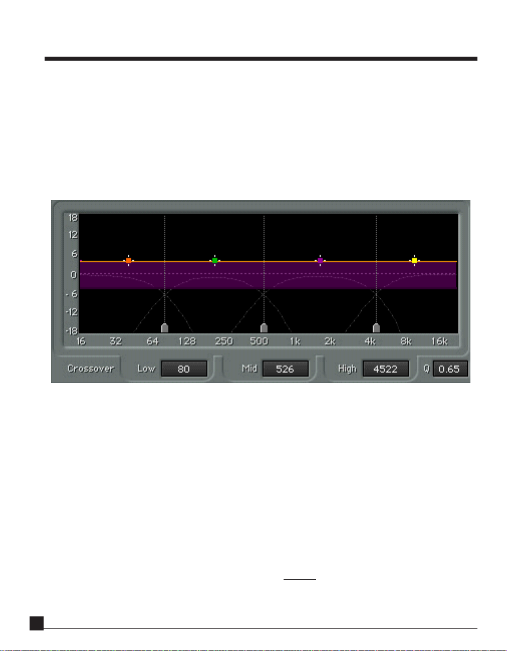
Chapter 3 — Controls and Interface
Main display area
DynamicLine™ Graph
Instead of individual gain reduction meters, which provide a limited amount of information, we felt that showing
the basic function of a multiband processor must include the gain change in each band plus the “resultant EQ” by
the settings of the crossover. Therefore we combined them into a new interface display.
If you have a crossover and set the output gains differently in each band, you have a 4-band EQ, in a manner of
thinking. Putting compressors into each band makes it a dynamic EQ. Therefore, the graph shows a large amount of
information:
• 3 crossover points (draggable)
• crossover slope (global)
• DynamicLine™ animated EQ curve (yellow line)
• maximum change in dynamic Range (the purple area)
• fixed gain (the brighter edge of the purple range)
• frequency center points (draggable)
• effective gain change (by comparing moving line to scaling on left edge)
This is a lot of information in a single display, but you’ll find it very intuitive after just a short time of using it.
Due to the complex nature of the possibilities of this processor, it’s best to give a complete example so that the list
above is clearly understood.
C4 Plug-In Manual
66
6
66
Page 7
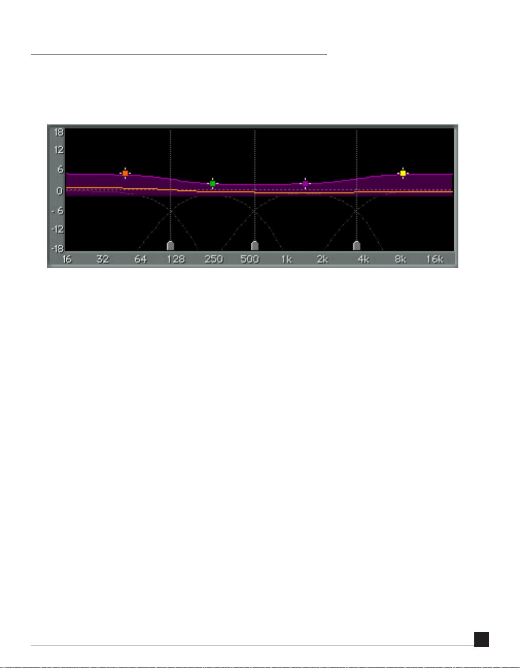
Display example
Let’s suppose that you only want to do compression, just as shown in the screenshot below, so we’ll refer to the
settings shown there (what is shown is the “Low-level Enhancer” preset with audio passing through the C4).
• The crossover points are shown by dotted straight lines and markers on the lower edge; the slopes can be seen
as shown by the dotted gray curves.
• The yellow line is both the “resultant EQ” and the gain metering at the same time.
ANGE
• The R
have an expander).
• Fixed
range.
• Band center points are shown by 4 markers.
• Gain metering is shown by the moving line, and by observing the scale on the display’s left edge, a general idea
of how much gain reduction (or increase) is achieved in each band.
controls the maximum gain change (if Range is negative, you have a compressor, if positive, you
GAIN
is the “output gain” of each compressor band is shown by the lighter purple edge of the purple
In this example about the display:
R
ANGE
is set to negative values, which means that the dynamic gain change for each band ranges downward (a
reduction) from the fixed gain edge. Dynamic gain reduction is compression (!), no question about that. The
purple area represents the R
within which the processor can change gain dynamically. If the R
ANGE
was set to
ANGE
a positive value, that band would be an upward expander, and then the purple range will extend above the fixed
gain line. The Expander function can be used for distinctive and innovative low-level processing, which is covered
in more detail in Chapter 4 - Range and Threshold Concept and Chapter 5 - Examples of Use. Multiband low-level
expanders are quite amazing and good tools to have.
C4 Plug-In Manual
77
7
77
Page 8

As you can see, G
purple shading is the G
AIN
is set to different positive values for each band. In the previous graphic, the colored edge of the
AIN
line. If you are familiar with the Waves C1 compressor, just think of the C4 as a group of
C1 compressors all in split mode. You compress the bass or some other band, then set the “makeup gain” for the level
you want the compressed band to have.
ANGE
The purple area shows the R
AIN
to the band’s fixed G
, and is relative to it. The G
of possible dynamic gain changes in each band. This dynamic gain is in addition
AIN
value is always shown as the lighter-colored edge of the purple
range.
Simply put, G
principle you should keep in mind is that
R
ANGE
the wanted gain change below and above the
In this example, the T
AIN
is always the highlighted edge of the purple band, and R
G
AIN
always takes place when the signal is well below the T
offsets it when the signal is well above the T
T
HRESHOLD
HRESHOLD
and other controls are set for the desired sound and do not affect the display or
HRESHOLD
.
ANGE
offsets it to the other edge. Another
HRESHOLD
, and
. Keeping this in mind will help you to setup the C4 for
graph in any way (except for the speed of the graph which is affected by attack and release times).
Crossover points
Along the lower edge of the graphic display are 3 crossover point markers. These can be dragged to adjust the
crossovers, or a numerical value can be typed into the control just below each marker.
C4 Plug-In Manual
88
8
88
Page 9

Q
Just to the right of the numerical crossover controls is the Q control, which adjusts the slope of the crossover filters.
All 4 bands are affected at the same time. The slopes are visible as dotted curves in the main window.
Q ranges from 0.10 to 0.75. Higher values mean steeper slopes, which give sharper divisions between the bands.
This doesn’t mean steeper slopes are better, otherwise there would be no reason to allow control at all. To achieve
more intense processing (greater compression, smaller peak-to-RMS ratios, etc.), steeper slopes can offer significant
benefit. To achieve more gentle processing and more inter-connected processing, lighter slopes will be more
appropriate.
• Q = 0.1 => -6dB per octave slope, gentle separation
• Q = 0.6 => -12dB per octave slope (default, and recommended)
• Q = 0.7 => -18dB per octave slope
• Q = 0.75 => -24dB per octave slope
Band center markers
Above the yellow line are 4 colored markers representing each band, which are quite powerful. Dragging any marker
can change 3 values simultaneously. Dragging horizontally will change the frequency center of a band (by changing
the crossover point related to that band). Note that changing the center of a band will also change the adjacent band.
AIN
If you drag the marker vertically, will change the G
ANGE
key changes the R
. You can lock into one direction by pressing and holding the Command key (Mac only)
for that band. Vertical dragging while holding the Option/Alt
during any dragging operation, which will help you avoid changing the other direction’s values, i.e., Commanddragging horizontally will not change the Gain value. (See other power-user tips in the WaveSystem manual; there
are many).
Summary of Band marker controls:
• Horizontal drag = Frequency center
• Vertical drag = Gain
• Option/Alt-vertical drag = Range
• Command-drag = lock into first direction moved (Mac only)
C4 Plug-In Manual
99
9
99
Page 10

Band controls
Each band has 7 controls.
Solo
At the top left corner of each band is the S
OLO
button, which allows you to listen to just that band, with processing
(post-compressor). The display also shows what you are actually hearing, so if you solo 2 bands, the display will
show 2 bands with the dynamic yellow line and purple ranges, as seen below.
Bypass
Just to the right of the Solo button is the Bypass control, which returns the entire band to a unity gain status with no
dynamic processing at all. The Gain control value is ignored. Therefore, if you want to simply have no dynamic
processing at all id‚œ band, but still wish to have control of the Gain, don’t use the Bypass control. Instead, set the
Range to zero and then use the Gain control as a fixed makeup gain control (which you can think of as a 1-band
EQ).
C4 Plug-In Manual
1010
10
1010
Page 11

Threshold
This determines the point around which the dynamic gain changes will take place; in other words the center point
of the R
ANGE
control. This control can be changed by vertically dragging the triangle beside the orange energy meter.
Each meter shows the actual level in that band (so if the band is very low, high, or narrow, the level in that band will
be low, most likely). It makes it very easy to set a Threshold; merely drag the triangle down until it is within the range
of motion of the orange meter. The value of the Threshold is displayed at the top of the meter. You can also type a
value into this display, or drag directly on it, as described in the WaveSystem manual. Note that only the first band is
labeled with “Thrsh”. No reason to clutter such a nice user interface, eh?
Gain
You can think of this control as the makeup gain for each band (or as an offset gain). In the Waves C1 compressor,
it is simply called Makeup. On many compressors, like the C4, it is called Gain, and is the output control of that
band, whether it is set to be a compressor or an expander. Just set the dynamic behavior (say, light compression) for
a band, then set the Gain control to the desired level.
It helps to remember that Gain takes place when the signal level is well below the Threshold — that is what we term
low-level Gain.
C4 Plug-In Manual
11
Page 12

Range
This is a deceptively simple control to let you set the maximum range of compression or expansion for each band,
in dB. For instance, if you set R
ANGE
to –6dB, you will not have more than –6dB gain reduction in that band, no
matter how deep you’ve set the Threshold. This gives you the flexibility to do low-level compression (as first offered
in the Waves C1), which is a way to “compress upward” a level of a band, without altering the transients above the
range.
Just think of it as a way to set the ratio and a maximum gain change at the same time. The bigger the R
ANGE
(negative
or positive), the more gain change you can have in that band, as well as having a higher ratio. For most compression
applications, just setting R
achieve limiting, a large negative R
ANGE
to -4 is quite sufficient, unless you are intentionally trying for a heavy effect. To
ANGE
can be used (try the Limiter Medium or Limiter Heavy setups as starting
points).
It helps to remember that Range is added as an offset to Gain, when the signal level is well above the Threshold —
that is what we term high-level Gain.
Attack
This is the classic compressor or expander attack control. It varies the speed with which the dynamic process will
take place, in response to an increase in input level. For example, if you have Attack set to 100ms on a compressor
setting, then the full value of compression will not occur until about 100ms. By varying the Attack time, you can
precisely control how prominent the transients are allowed to be. With very fast Attack times the output signal will
have very little attack remaining (which can be an effect), but many times such fast attack times are the reason that
multiband compression can have a less than desirable result. Longer Attack times can increase the peak-to-RMS
(the level of attack-to-sustain, so to speak) of a signal because the longer attack allows more of the initial sound to
pass through before compression occurs. After the compression begins, it lowers the rest of the sustained sound,
therefore increasing the dynamic distance between the beginning sound (transient) and the sustained sound.
Release
This is very much like release controls on other dynamic devices. It varies the speed with which the dynamic process
will stop taking place. If you have Release set to 500ms on a compressor setting, then compression will continue for
500ms (a half-second). One point to remember is that the 2 controls in the Global section called B
R
ELEASE
will also affect the release behavior; this is described later in this chapter in the Global controls section. The
ARC™ technology can profoundly affect the way the release works, and is discussed in the Global controls section.
C4 Plug-In Manual
12
EHAVIOR
and
Page 13

One advantage of a multiband compressor is that slower attack and release times are not as necessary as in wideband
compressors. The intermodulation distortion (IM) described previously was caused by compressors that were “tracking” the low-frequency signals too closely, so setting attack and release times to slower values helped reduce the IM
distortion, but also prevented the type or amount of desired compression from being achieved. Since each band has
it’s own attack and release controls, they can be set for optimum dynamic processing with minimum unwanted
distortion. If you have Release times that are too slow, then a band could be compressed (reduced in gain) for a
longer period of time after the signal has already fallen below the Threshold. Release times that are too fast will still
produce distortion.
Tip: Setting Attack and Release
The easiest way to hear how a too-fast Release time causes distortion is simply to Solo the low band (1st band). Set
the attack and release times to very fast values, say 5ms each, with the Behavior mode set to Electro and the Global
Release set to Manual. Set the Range to –10, and the Threshold deep enough to get a lot of movement in the graph.
Most likely, the bass will be somewhat distorted and fuzzy (just use the 1st band’s Bypass button for comparisons).
Part of correctly setting the release (and attack) controls will be to find values that give the desired dynamic processing
without causing distortion. Let’s face it, most of you probably wish to use multiband to increase the density
(“loudness”) of your mixes (and hopefully not to poor effect), so we’d like to suggest a few points so that you will
obtain the best possible sound. Just remember that attack should be long enough to let the transients pass through
for the desired punch, and the release long enough to minimize distortion.
The higher the frequencies, the less that distortion is factor, and the issues become somewhat more esthetic. Too fast
an attack in the mid and high bands and the sound will be squished, as the compressor “clamps down” on the sound.
Too fast a release and the tonal balance of the sound will be altered; you can change this by simply adjusting the Gain
of the higher bands so that the bands are not out of balance.
Master controls
Whatever the settings are on each of the band’s controls, the Master controls will add or subtract from those values.
Master Threshold
Master Threshold moves all 4 bands’ Thresholds simultaneously. This is a quick way to adjust the overall compression
in a “strapped” mode. These controls keep the relative values intact as they are adjusted
C4 Plug-In Manual
13
Page 14

Master Gain
All 4 bands’ Gain controls are moved together when the Master Gain control is adjusted. Best used to adjust the
output level for Bypass comparisons. Set the level so that it is subjectively the same subjective level as the Bypass
level.
Master Range
Master Range adjusts all 4 bands’ Range. This is ideal for increasing or decreasing the overall amount of compression or expansion. Generally, if you increase the Master Range, you may have to raise the Threshold or the Gain to
compensate for the increased compression.
Master Attack
As in the other Master controls, adjusts all 4 bands simultaneously. Best used in small amounts for general adjustments. Better to adjust each band individually for optimum effect and minimum artifacts.
Master Release
Similar to Attack in that the Master Release is best used in small amounts for general adjustments. Better to adjust
each band individually.
ARC™
Waves Auto-Release Control Technology, originally developed for the Renaissance Compressor, is ideal for the C4
Multiband Parametric Processor. The ARC™ technology was created to optimize the release time in order to achieve
the most transparent behavior. For most people this means that you can maximize RMS level with a minimum of
distortion. If the Release control is set to ARC mode, then the release time of each band is calculated every sample
for the minimum distortion. The value of the release time you set in each band becomes the reference value from
which the actual release time is calculated by ARC at any given instant.
In Manual mode, the release time in each band is a fixed value, although the sound is still affected by the Global
Behavior control (see next entry).
C4 Plug-In Manual
14
Page 15

Behavior
Originally developed for the Renaissance Compressor, the Behavior control is selectable between Opto and Electro
modes.
• Opto is a classic modeling of opto-coupled compressors which used light-sensitive resistors to control the
amount of compression (in the detector circuit). They have a characteristic release behavior of “putting on
the brakes” as the gain reduction approaches zero. In other words, the closer the meter comes back to zero, the
slower it moves. (This is once the gain reduction is 3dB or less). Above 3dB of gain reduction, the Opto mode
actually has faster release times. In summary, Opto mode has fast release times at high gain reduction, slow
release times as it approaches zero GR. This can be very beneficial for deeper compression applications.
• Electro is a compressor behavior invention by Waves, in that it is very much the inverse of the Opto mode. As
the meter comes back to zero, the faster it moves. (This is once the gain reduction is 3dB or less). Above 3dB
of gain reduction, the Electro mode actually has slower release times, much like a mini-leveler, which minimizes distortion and optimizes level. In summary, Electro mode has slow release times at high gain reduction,
and progressively faster release as it approaches zero GR. This has very good benefits for moderate compression applications where maximum RMS (average) level and density is desired.
Knee
This Master control affects all 4 bands’ knee characteristics, ranging from softer (low values) to harder (higher
values). At the maximum value, the Master Knee control tends to give the sound a harder edge, with a punchier
overshoot-style character. Adjust to taste. The K
control. To achieve limiter-type behavior, use high K
NEE
and R
NEE
settings.
ANGE
together interact to give the equivalent of a ratio
C4 Plug-In Manual
15
Page 16

Output gain fader
Ranges from -18 to +18dB, and is also 48bit double precision, dithered to 24bit before handoff to the TDM bus.
C4 Plug-In Manual
16
Page 17

Chapter 4 — Range and Threshold concept
The concept of ‘Threshold’ and ‘Range’ instead of the traditional ‘Ratio’ control creates some very flexible and
powerful uses for the C4. They include low-level compression and expansion, giving you multiband “upward compressors” and noise reducers.
Old school/another school
In the classic compressor approach, if you set a very low Threshold with any given Ratio, extreme amounts of gain
reduction of high level signals may occur. For example, with a Ratio of 3:1 and Threshold of –60dB will result in a
–40dB gain reduction for 0dBFS signals. Such a case is rarely desirable, and in general you would only set such a low
Threshold in a typical compressor when the input level is also very low. In common practice, more than -18dB of
gain reduction or +12dB gain increase is rarely needed, especially in a multiband compressor.
In the C4, the concept of ‘Range’ and ‘Threshold’ comes in very handy. It lets you first define the maximum amount
of dynamic gain change using the ‘Range’ control, and then determine the level around which you want this gain
change to take place using the ‘Threshold’. The actual values of these controls depend on the type of processing
which you want.
If Range is negative, you’ll have downward gain change.
If Range is positive, you’ll have upward gain change.
The real flexible fun happens when you offset this dynamic Range with a fixed Gain value.
High-level compression
High-level compression in C1. Ratio is 1.5:1, Threshold is -35. Equivalent C4 setting would have Range set to about
-9dB, with Gain set to 0.
C4 Plug-In Manual
17
Page 18

If you are interested in conventional compression (termed here ‘high-level compression’ because the dynamics of
the compression happens at high levels), simply set the Threshold to high values, between –24dB and 0dB, and the
Range to a moderate negative value, between –3 and –9. In this way the gain changes will take place at the upper part
of input dynamics — just like a normal compressor will do.
High-level expansion (upward expander)
An upward expander from the C1, with a ratio of 0.75:1, Threshold at -35. Equivalent C4 setting would be a Range
of +10 or so, quite a bit more than you’d probably ever need. Shown only for clear example.
To make an upward expander (an “uncompressor”) to restore overly squashed dynamics, simply reverse the Range
setting.
Make the Range be a positive value, say between +2 and +5. Now whenever the signal is around or above the
Threshold, the output will be expanded upwards, with a maximum gain increase of the value of Range. In other
words, if Range is +3, then the maximum expansion will be 3dB increase.
Low-level compression
The low-level processors are where we start to have even more fun. By using the fixed Gain control to offset the
Range, you can affect only the lower-level signals.
If you are interested in increasing the level of soft passages, but leaving the louder passages untouched, (termed here
‘low-level compression’), set the Threshold to a low level (say –40 to –60dB). Set Range to a small negative value,
such as -5dB, and set Gain to the opposite value (+5dB). The audio around and below the Threshold value will be
“compressed upward” a maximum of 5dB, and the higher audio levels will be untouched, including their transients.
C4 Plug-In Manual
18
Page 19

This will cause high levels signals (i.e. that are significantly above Threshold) to have no gain Change – since at high
levels the Range and Gain controls are opposite values and together they equal unity gain. While around and below
the Threshold, the Range is increasingly “inactive” and therefore approaches a zero-gain value. Gain is a fixed value,
so the result is that the low level signal is increased by the Gain control, achieving the so-called “upward compression” concept.
This is very clear when you see this behavior on the C4 display. Simply look at the yellow DynamicLine while the
input signal is low or high, and see the resulting EQ curve.
In a multiband compressor application, this low-level compression is very handy to create a dynamic ‘Loudness
Control’ that could boost the LOW and HIGH bands only when their levels are low, as just one example.
Upper line shows Low-level compression (upward), achieved when Range is negative and Gain is equal but positive.
Lower line shows Low-level expansion (downward), achieved when Range is positive and Gain is equal but negative. Graph is taken from C1 to help visualize the gain structures in the C4.
Low-level expansion (noise gate)
If you are interested in a noise gate for a particular band or bands, set Range to a positive Value, Gain to the inverse
of the Range, and Threshold to a low value (say -60dB). Similar to the above example, at high levels the full dynamic
gain increase set by the Range is retained, and is fully compensated for by the Gain. While around and below the
Threshold, the dynamically changing gain comes closer to 0dB, and the result is that the fixed negative Gain is
applied to the low level signal — which is also known as gating (or downward expansion).
C4 Plug-In Manual
19
Page 20

“Upside down” thinking
These low-level examples may seem a little inverted to what you would expect. For instance, that a noise gate would
have a positive Range.
If you just remember that when the signal goes around the Threshold, then the Range becomes “active”, and that the
Threshold is the halfway point of the Range. So whether Range is +12dB or –12dB, then audio 6dB above and 6dB
below the Threshold is where the “knees” of the dynamic change will occur.
Positive Range
Then, if Range is positive and Gain is set to be the negative of Range (opposite but equal), then around and above
the Threshold all audio will be a 0dB gain (unity). Below the Threshold, the Range is not active, so the Gain (which
is negative) “takes over” and reduces that band’s gain. This is what gives the downward expansion.
Negative Range
Another seeming example of the “upside down” concept is that low-level compression takes a negative Range.
Again, remember that in the C4, whenever the audio is around the Threshold, the Range is active.
So, if we set Range to negative, anything around or above the Threshold can be reduced in gain. However! Here’s the
tricky part: if we set Gain to perfectly offset the Range value, then everything well above the Threshold has no
effective gain change at all, which means everything well below it gets “lifted up”. (If you take this just a bit further,
you’ll figure that all audio exactly at the Threshold will have half of the Range’s value in positive gain).
One more way to think about it
Here is another bit of help so that you can really learn and use the power of the C4 to its fullest capability. We’ll take
another example from the Waves C1 Parametric Compander, our one-band processor (it also does wideband and
sidechain).
It has a typical ratio and makeup gain control and has been widely used for upward compression (both wideband
and splitband parametric usage).
The C4 Multiband Parametric Processor has a very similar compressor law as the Waves C1 and the Waves Renaissance Compressor. This model allows the “compression line” to return to a 1:1 ratio line as the level continues to
increase. In other words, there is no compression of the low signal, compression around the Threshold, and once
the signal goes quite a bit past the Threshold, the compression tapers off back to a 1:1 line (no compression).
In the graphic shown, you can see this exact type of line. The ratio is 2:1 and the Threshold is –40dB. The line is just
curving a bit (-3dB down point) at the –40 input (the scale at the bottom). Output level is the scale on the right
vertical edge, and you can see that at about –20dB, the line starts curving back to a 1:1 line.
C4 Plug-In Manual
20
Page 21

So, very high-level audio peaks between 0 and –10dBFS are not touched at all, audio between –10 and –40 is
compressed, and audio below –40 is not compressed, but is clearly louder at the output than at the input. This is low-
level compression, or “upward compression”.
Such a trick is very useful and has been implemented by classical recording engineers, mastering houses, and classical broadcasting. Low-level compression can “lift” soft sounds up gently and leave all the high-level peaks and
transients completely untouched, reducing the dynamic range from the bottom upwards.
We did say that the C4 was “very similar” to the C1, but different in a significant way: the Threshold defines the
midpoint of the Range. Therefore, to achieve the same curve in the C4 as shown here, the Threshold on the C4
would actually be about –25 with a Range setting of +15.5dB. Now this is a very large amount! The example shown
here was merely to make it obvious; we picked the 2:1 line only because it is easier to see on the page. In reality, lowlevel compression that lifts the softer audio up 5dB is equivalent to a approximate ratio of 1.24:1.
Lifting the low-level up about 5dB is a good example for several reasons. It is (1) a very realistic setting that could be
equal to what is being done by the previously mentioned engineers; (2) only raising the noise floor by an acceptable
amount for many applications; (3) easy to hear on nearly any type of audio, not only classical. In the Load menu of
the C4 are a few factory presets with names beginning “Upward Comp…” that are good points to learn more about
this concept. More presets are in the C4 Setup Library.
In the next chapter there are more specific examples of using low-level processing (compression, expansion) that
are very good starting points as well as models for learning.
C4 Plug-In Manual
21
Page 22

Chapter 5 — Examples of use
As a “Dynamic Equalizer”
Because of the R
ANGE
and T
HRESHOLD
concept explained in Chapter 4, it’s easy to think of the Waves C4 as a dynamic
equalizer which allows you to set 2 different EQ curves (low level EQ and high level EQ), then set the transition point
between them. The transition is the Threshold control, which sits at the halfway point of the Range value. Of course,
it is not a “morphing EQ” but it most certainly is a dynamic process that moves between two different EQ settings.
Here’s an example. Load the Low-level Enhancer factory preset from the Load menu.
You can see the purple range has 2 distinctly different “curves”, the lower edge and the upper edge. The lower edge is
flat, the upper edge has an obvious “loudness boost” to it.
Now remember that this is set as a compressor, so when the signal is low, the upper edge of the purple band will be
the EQ; when the signal is high (and compressed) the lower edge of the band will be the EQ. So for this example,
with no compression (low-level sounds) there will be a loudness boost (more highs and lows); with compression,
the sound will have a “flat EQ”.
- Play some audio thru the Low level Enhancer setup.
You’ll see that the audio is compressed downward toward the flat line, so that as more compression occurs, the
effective EQ curve (although dynamic) is flat.
- Now reduce the input level to the C4, or play a quiet section of music so that there is little or no compression.
You’ll see that the audio is not compressed very much at all, so the DynamicLine “sticks” to the upper edge more. By
setting the Gain control of each band, you control the low level EQ of the processor; by setting the Range control of
each band, you control the high level EQ.
C4 Plug-In Manual
22
Page 23

How to create your own dynamic EQ setting (for low-level enhancement):
1. Set the Range to the amount of gain reduction desired in each band; this also sets the “EQ” of the compressed
signal.
2. Set the Gain of each band so that the desired low-level EQ is seen. For instance, you may want a song to have
a little more bass when it is soft, so set the bass band(s) so that their gain values are higher than the other
bands.
3. Attack and release values should be appropriate for the frequency band. (This is why it is generally easier to
work from a preset, then tweak it for what you need).
4. Set Threshold for the desired behavior. What you want is for the high levels of the song to be compressed
closer to the lower edge of the purple area (to get the EQ for the high-level); therefore, the Range values should
not be very big. Otherwise you’ll be compressing a great deal, which is probably not what you want for most
applications.
As a vocal processor
Voiceover or singing both have similar needs in compression and de-essing, and a multiband device can be quite
good for this. In fact, the C4 also lets you work as an EQ as well, as previously mentioned.
• Load the Voiceover preset from the Load menu.
• Any of the bands can be bypassed! If you don’t need de-popping, just bypass band 1, for example.
• Band 1 is for de-popping, without affecting the deep bass.
• Band 2 is set rather wide, to perform most of the work.
• Band 3 is a de-esser, with a 1dB boost (note that the Gain is 1dB higher than bands 1 and 2).
• Band 4 is just the “air” of the voice, just a tad of compression and boost of 2dB above bands 1 and 2.
• Optionally, you can set Band 1 G
AIN
to –10, with R
ANGE
set to zero, and the Low Crossover set to 65Hz. This
can lowcut any pops or thumps but may remove some low stuff that is important; do it only if there are real
problems.
Now, while playing voiceover or vocals through the C4, solo each band to hear what it will affect. Band 2 certainly
has all the “meat” of the voice, and by using Band 1 set to a low crossover, any loud pops or rumble will be isolated.
Adjust the Thresholds of each band so that you have reasonable compression on band 2, with relatively strong deessing on band 3. Then adjust the Gain controls to balance the tonality of the voice.
C4 Plug-In Manual
23
Page 24

The Q and Knee controls are set very high in this preset (created primarily for voiceover), and can certainly be
softened for a singing voice. Try lower Q and Knee values with smaller Range settings for more gentle compression,
while still giving you powerful de-essing and “air limiting”.
As a Mastering Processor
We approach this subject with a bit of sincere care. Mastering is a somewhat misused word at this time, and is not
limited only to making CDs. Anyone who is preparing a “Production Master” for duplication or broadcast is truly
mastering, that is, making the final copy and tweaking it. It happens in film and video (color correction, etc.), in
print, and definitely in audio. This includes preparation of nearly every commercial, show, or production element
in the entire media world.
The Mastering Guild (the audio group) has emphasized that CD mastering is an acquired art and craft, not an
equipment list, and the most important tools to such an engineer are their ears and their monitor configuration.
They know what things should sound like; the question is how to adjust something to get it to where it can be. It’s
not through presets or guesswork. Historically, it has been through apprenticeships, at best.
That aside, we recommend trying the Multiband Opto Mastering preset, or the Basic multi preset. Either one will
give you reasonable compression and increased density of your mix.
To enhance low-level signals (a great way to boost level without squashing dynamics), try the Upward Comp +5, or
+3 version of the preset. This is great for adding level without losing punch.
To fix a mix
Most of the time, you want to use relatively equivalent Gain and Range settings across the bands so to not change
the spectral balance too much. However, it’s not a perfect world, and many mixes are not perfect either.
So let’s say you have a mix that has too much kick, the right amount of bass guitar, and needs a little “cymbal
control” and de-essing.
Load the BassComp/De-Esser preset.
• Adjust the bass Threshold, band 1, until you have some compression.
• Adjusting the band 1 Attack control will let through more or less of the kick itself.
• Adjusting the band 1 Gain control lets you set the overall level of the kick and bass. If the compression pulls
the bass guitar down too much, you might increase the Gain until the bass is right, then adjust the Attack
value to control the kick drum punch until it has a better balance.
• Faster attack times will let less kick through; slower times will let more of it be heard. In fact, with too long of
a setting, you may actually increase the dynamic range between the loud kick and bass guitar, which isn’t what
the example was all about.
C4 Plug-In Manual
24
Page 25

Now for the “cymbal control” and de-esser, you’ll follow a very similar procedure that you did for the bass band.
• Adjust the band 3 Threshold until you have some compression.
• Adjusting the Gain control lets you set the overall level of the “ess and cymbal” band.
• Setting the Attack too fast will destroy the consonants of the voice, so try about 12ms as a starting point.
Notice the fast release time in the preset, so that the compressor “gets out of the way” as soon as the sound is
gone.
• Adjust the Crossover so that you are affecting only the needed areas (using the Solo button is very handy in
this regard).
Now for some more fun! Band 2 and 4 can be used as EQ controls. Since the Range is set to zero for both of those
bands, when you adjust Gain, you’ll see that each band simply moves as a fixed offset (that’s what EQ is, after all).
As an UN-processor
Sometimes you might get a track or recording that has been previously processed, and possibly not in a very flattering way. In other words, someone might have seriously overcompressed the track.
To some degree the squashed dynamics can be restored by using upward expansion, which is the exact opposite of
compression. As the signal goes around or above the Threshold, the signal is increased in gain.
Upward expansion takes more time to adjust because you must try to find the subjectively equal settings of what
was done to the sound, and even if you know the “numbers” on the original processor, the numbers really don’t
relate from one processor to the next very well.
• Load the Unprocessor preset.
• Notice that all Ranges are set to positive values so that the gains will be increased when the signal goes around
or above the Threshold.
• Adjust the Master Threshold for some reasonable expansion.
Now it is important to point out that the attack and release times are absolutely critical to the way the expansion
works. In most cases of overcompressed material, the peaks and punch have been mightily squashed down, so a fast
attack time will help restore these peaks. Longer release times help bring the presence and sustain back into the
material.
However, let’s go one step further and suppose that you have a mix that has “hole-punching” or “pumping”. These
are tricky, but can be restored to a degree. In the case of hole-punching, this is when a compressor has overshoot of
the gain reduction, that is, it over-reacts to a peak signal and applies too much gain reduction to the signal. Many
times the peak itself was never compressed, just the audio after the peak, so you would want to use a slower attack
time to avoid expanding the peak even higher, and carefully adjust the release time to “fill in the hole”. It’s tricky
enough to do this on a wideband expander such as the C1, and even more so on a multiband.
Best thing to do in this case is to try to determine if you should use a wideband expander (such as the C1 or
Renaissance Compressor). Using a multiband upward expander would be best for situations where specific frequency ranges had been overcompressed, such as a mix with too much compression on the bass. Another example
would be too much compression on a drum submix and you need to restore the attack of the drums but not the low
frequencies, so you could use a mid- and high- frequency upward expander and ignore the lower frequencies.
C4 Plug-In Manual
25
Page 26

You can load the Unprocessor and simply Bypass any band you don’t need. Here’s another tip: to bypass a band but
still have it available as “EQ”, simply set the Range control to zero and use the Gain control to set the EQ level in that
band.
As a noise reduction processor
If you recall the principle of low-level gain and high-level gain explained previously, it is easy to setup the C4 as a
dynamic noise reduction processor, with up to 4 bands if needed.
To remind you just a bit, Gain is applied to the low-level signals, and Range is added to it on high level signals.
To set up the C4 as a 4-band noise reduction processor:
• Find a section of audio where only noise is present, and loop it for preview.
• Listen to each band of noise separately (using Solo) and determine the amount of noise reduction you want
to apply to this band. Set Gain equal to the amount of noise reduction wanted in each band (a negative value).
• Set Range to exactly compensate for the gain reduction in low levels — that is the Range should be exactly the
inverse of Gain (if Gain=-12dB, Range=+12dB).
• While previewing the noise segment, set Threshold in each band such that it is just enough above the noise
energy in this band, so that you hear enough noise reduction in that band.
• It will be useful here to use a hard Knee setting (set the Knee control in the Master control section to its
maximum).
Now preview an audio segment where the wanted signal is present, and make sure it is indeed enough above the
Threshold(s) so that no gain reduction takes place (the yellow line is at 0dB gain).
Pay attention to the problematic passages, where the signal fades out or other soft sections where the audio comes
closer to the noise level; careful adjustment of Threshold is required there to avoid too much degradation of the
signal itself.
C4 Plug-In Manual
26
Page 27

Chapter 6 — Preset descriptions
The Factory Preset Menu:
In general, “factory presets” should be good starting places to save you time, easy for you to tweak, and for the most
part, be relatively self-explanatory.
To the extent that they don’t completely explain themselves, here are further details about each of the presets listed
here.
The Load menu is where these are found.
For more information on the Load/Save system, and many other powerful features that you only have to learn one
time to be able to use in every Waves software processor, check the WaveSystem manual for great power tips.
C4 Plug-In Manual
27
Page 28

General tips!
Here is a recommended order for adjusting a preset, even if you have no intention of “using presets”. They are
merely good places to start. Create your own library by using our User Preset command in the Save Menu.
• In almost every setup, moving the Master Threshold first is the best starting point.
• Adjust the Master Range control for more or less dynamic processing (changes ratio and amount of process-
ing simultaneously).
• Then adjust the Master Gain so that if you Bypass, the sound is about the same level so that it is easier for you
to make comparisons.
• Next, adjust each of the band’s Thresholds to get the desired amount of processing in each band.
• Next, fine-tune the Attack and Release controls. Longer attacks may mean you have to adjust the Threshold
downward to maintain the action you want (and shorter ones may mean you need to raise it).
• Next, if needed, adjust the Gain of each band to rebalance the compressed outputs.
The Factory Presets
Full C4 reset
This is also the default setting that C4 opens with when you first insert it on the TDM bus. It is a easily adjustable
compression setup with moderate Range. The Gain is set to zero so that it is essentially unity gain for low-level
sounds.
Band 1 is set for low bass, to eliminate modulation distortion. Band 2 does the main work. Band 3 is in a de-esser
range, and Band 4 is the air band limiter.
Basic multi
Based on the default setting above, but with deeper thresholds, plus it has a positive Gain of +4, so it is closer to a
unity gain when bypassing for most mixed pop material with peaks between -6 and -2dBFS.
Hard basic
Master Range is bigger, so the ratio is higher and there is more compression. However, the attack times are slower
than in Basic Multi, so the transients are still quite present and untouched. A punchy preset.
Deeper
Not a “flat” preset, by any means, this has deeper Ranges on the high end, which means the signal will be bassier as
it gets louder, and more compressed in the high end as it gets louder. Attack and release times are faster, so the
compressor grabs more.
C4 Plug-In Manual
28
Page 29

Low-level Enhancer
A classic loudness enhancer as described in Chapter 4 in the Low-Level Compression section. As the sound gets
louder, it approaches “flat compression”, but all low-level sounds will have the bass and treble boosted, as seen by the
upper edge of the purple Range band.
This is not a particularly subtle preset. To reduce the boost, simply lower the Gain of Bands 1 and 4 (they are preset
to 4.9, which is 3dB above the middle two bands). Try only 1dB (set them both to 2.9) and then you have a very nice
subtle low-level enhancement setup.
Upward Comp +3dB
A gentle upward compressor with flat response. It lifts the low-level sounds by 3dB at the average Threshold of 35dB. Lower the Master Threshold for more subtlety, raise it for more pronounced effect.
Note the crossover settings are different from the +5 setup. Band 1 is set to 65Hz for the very low bass; Band 2 is the
next octave and primarily deals with the fundamental of the bass guitar and meat of the kick; Band 3 is very broad,
from 130Hz to 12kHz; doing most of the work; and Band 4 is the air compressor. These points give greater control
over the bass (dividing it into 2 bands), but have no “ess-band” range.
If upward compression provides too much of a boost in the highs (a common result due to the lower overall energy
of HF), then simply lower the Threshold in the high band.
Upward Comp +5dB
Similar to the previous setup, but with different crossover points, for different flexibilities. This one is more similar
to the Basic Multi, with crossovers at 75, 5576, and 12249, so that you have bands for Low Bass, Broad Mid, “Ess” or
presence band, and the Air. These points give greater control over the high end (2 bands).
This is a more aggressive setting, the main difference being the crossover points, which changes the Thresholds
significantly from the +3 setup.
Easily made more or less aggressive by changing the Master Gain setting. If upward compression provides too much
of a boost in the highs (a common result due to the lower overall energy of HF), then simply lower the Threshold in
the high bands.
Multi Opto Mastering
Now we are going into areas that haven’t actually existed yet, to our knowledge. A multiband opto-coupled device!
This is a rather transparent setting for mastering and pre-mastering. Even though ours is virtual, the gentle release
times that become ever slower as they come back to zero gain reduction really have the sound and behavior of
opto’s, just as the Renaissance Compressor does. The longish attack and release times of this setup let the processor
gently increase lower levels while having the classic setup of a high-level compressor.
Changing the Master Release and making the release times significantly faster will still preserve most of the transients but markedly increase the average level.
C4 Plug-In Manual
29
Page 30

Multi Electro Mastering
The other end of the spectrum, insofar as the mastering goes, with much more aggressive settings throughout than
the Opto setting described previously.
With fast attacks and releases, deep Range, steeper slopes, ARC system, Electro release behavior, and hard knee, this
one is starting to be a little dangerous if you push it (although certainly not over the top).
With this setup and the Multi Opto Mastering preset as bookends, there are many levels in between to provide
varying levels and behaviors. Working with both of these presets defines a very broad range of high-level compression settings to create. (We’ll leave that to you!)
2-band HF noise reducer
Borrowing from the downward expander setups of the C1, this preset splits the high band into the high-hiss and
“shhh” ranges for more precise control. We’ve heard stories of users over the years who carefully used multiple C1’s
to gently reduce noise, so this is just a nod in that direction.
The bands 1 and 2 are in bypass, but are already set for rumble and low-mid noise reduction. Simply take them out
of Bypass.
To adjust, Solo the band to adjust, then drag the Threshold so that the undesirable noise is reduced without adversely affecting the audio you want to keep. Move Threshold up to increase noise reduction. Optimizing each band
in this way will yield the greatest signal-to-noise increase and minimize noise modulation.
For even more noise reduction, increase the Gain setting and make sure to set the Range to the same amount, but
negative (Gain=9, Range=-9).
Attack and release times are very similar to gate operation. A slower attack time will make the band open slower; a
slower release time will make the band close slower (have more noise before it reduces gain). Therefore, slower
attacks and faster releases also increase the noise reduction behavior.
Rumble and hiss reducer
All the points made in the previous preset commentary, 2-band HF noise reducer, also hold true for this preset,
which was designed specifically to reduce rumble and hiss.
Crossovers are set for 75Hz and below, and a hiss band centered around 7.5kHz.
If there is also a need to reduce the very high-hiss noise, simply take Band 4 out of bypass. Band 2 is probably not
needed very much unless you have a very noisy source. One possible drawback is that Band 2 is very very broad
(over 5 octaves), and unless carefully set, noise modulation (the sound of the noise coming and going) will be
distracting. Research performed for speech therapy and recognition has shown that a constant noise floor is more
tolerable than a noise floor that constantly changes volume.
C4 Plug-In Manual
30
Page 31

4-band noise reducer
An aggressive noise reducer preset, with fast attacks (to preserve the original sound), fast releases (to reduce noise
quickly), 4 bands of operation (possibly more than you need), and hard knee.
If you don’t need a band (just solo it to see if there is really any objectionable noise in that band), simply Bypass that
band.
UNcompressor
Since there has been so much work done in the direction of multiband compression and limiting, it seemed only
fair that a preset that tried to go in the other direction would be added.
Admittedly, there is most likely a bigger challenge in undoing an over-compressed signal than in the original mistake! Wideband upward expansion is probably the first method you should try (with the Waves C1 or Renaissance
Compressor), unless you can positively identify a mix that has already had some multiband or de-essing (parametric) type of compression mis-processing.
Otherwise, trying to use a multiband upward expander to fix a mix that had wideband over-compression is not
advisable, as the gain changes applied in the first place would have been across the entire band.
However, as flexible as the C4 Multiband Parametric is in the other areas discussed in this manual, it certainly is
equally capable of producing amazing UN-compression in the multiband arena.
Keep in mind that the attack times are what create the transients, and if you’ve already got good transients in the mix
but the audio after the transients is what is over-compressed, make your Uncompressor Attack time longer, to avoid
making even bigger transients.
Soloing each band and adjusting its Attack and Release times so that the transients are natural, the compression is
relieved and the audio sounds more relaxed and open is the trick.
The preset has not attempted to set attack and release times, as this is so highly dependant on the source material, we
simply set all 4 bands to attack times which are moderate for the frequency band, and equivalent release times across
all 4 bands.
BassComp/De-Esser
A common problem with small studio mixes is the low end, due to near-field monitors, improper room lowfrequency absorption, beer, and demanding clients. Another common problem is the lack of enough de-essers to go
around, and furthermore, the insistence of drummers bringing their full-size, heavy cymbals into the studio.
The result is often a mix with a low end that is too loud, and/or an improper balance between the bass guitar and the
kick drum, plus a high-end that might need de-essing and “de-cymbaling”. The most challenging of these situations
has very bright guitars and cymbals and dull vocals. Of course, the best way to solve these issues is to de-ess in the
mix, use very light cymbals, and, well, better engineering on the low end!
This preset uses only 2 bands (the most common application of multiple C1’s), for bass compression/control, and
de-essing.
C4 Plug-In Manual
31
Page 32

Band 1 is set to 180Hz which covers the main part of the kick drum and almost all fundamental notes of the bass
guitar or other bass line. Band 2 is a bandpass de-esser centered at 8kHz.
Attack and Release controls are the critical controls. With a faster attack on Band 1, the kick can be controlled
separately from the bass line with reasonable precision. Soloing the band will help in setting the Release time so that
distortion is minimized (too fast a Release will cause the compressor to follow the bass wave itself, a form of modulation distortion that even multibands are susceptible to).
It’s the same for Band 3; the Attack time (at 12ms) allows enough transients of the snare and consonants of the
singer that there is not too much dulling of the sound, but the sustained high-frequency material, such as esses and
cymbals, may be controlled quite well.
Bands 2 and 4 can be used as EQ, as the Range is set to zero.
BassComp/HiFreqLimit
A variation on the previous setup, except that instead of a bandpass de-esser, the entire high frequency is a shelving
compressor/limiter. Sometimes quite useful if there has been too much “air EQ” applied in the source material.
Pop Vocal
Admittedly a bit trendy, this preset is not flat at all, with a significant boost to the high end. Pop records, especially
R&B ballads, have recently been produced with a very bright sound. The common practice of boosting the highs
from about 5kHz, plus plenty of “air”, requires strong de-essing (sometimes twice!) to control the large increase.
This preset does both in one step, plus provides overall compression in band 2 (the broad middle area does the most
compression work).
For more effect, increase the Gain of bands 3 and 4, and increase the Range to match (same as Gain but negative). In
this way, the total gain reduction also increases as the fixed gain increases.
Vocal
Basic compression for a singing voice.
Band 1 is a de-popper, and may be bypassed, or to use as EQ, set Range to zero.
Band 2 is the main compression band. One reason this is done is to avoid putting a crossover point in the middle of
the critical vocal range (300 to 3kHz). Even with phase-compensated crossovers, the voice is the most demanding
source and proof for our ears, as we’ve been acclimated to it for a very long time and can detect very low-level
changes.
Band 3 is a de-esser centered at 6.5kHz. Again it is easiest to adjust a de-esser by listening to the sidechain, which
means in the C4 you simply Solo the band.
Band 4 is set to be an “air compressor” or limiter; alternately, it can be a straight EQ by setting the Range to zero.
C4 Plug-In Manual
32
Page 33

Voiceover
Announcers like compression, and need de-essing, so this preset provides both. As in the Pop Vocal preset, the high
end has a little boost (announcers like this as well).
To adjust EQ, change the Gain settings of each band. To control the amount of compression, adjust the Thresholds.
For a true “punch through the clutter” classic sound, follow the C4 with the Waves L1, using its Voiceover preset.
Too Much Limiting
Now what exactly should we say about this preset?
You can call it instant radio if you wish, as it does represent the type of processing that is applied by some radio
stations in order to be as loud as possible, and they do so to recordings that have already been processed to be as loud
as possible! Great for loops and remixes.
Not in the menu
We’ll be posting new presets on our web page, www.waves.com, and in future releases. And if you have some presets
you love, we’d appreciate it if you would send us a copy for posting in our User Presets section on the web.
One example shown here but not in a preset simply shows 4 different configurations at the same time: compression,
expansion, EQ, and noise reduction. There’s not much of a reason to make a preset for this, as the audio that
requires this setup is not in very good shape, and highly unlikely to match anything you might need!
Band 1 is high-level compression (to control bass a bit)
Band 2 is high-level expansion (to add some low-mid snap)
Band 3 is EQ
Band 4 is low-level downward expansion (hiss reduction)
C4 Plug-In Manual
33
Page 34

Chapter 7 — Essential concepts (and history)
Intro
The C4 is a wonderful, powerful tool, and although it offers many functions in a single processor, nothing can
replace your careful work in the process of mixing audio, using de-essers in the right place, applying compression
appropriately, and so forth.
Some of the trouble that multiband compression has caused has been merely because the engineer “gets into” the
sound too much. The solution is to try the most powerful control on any audio device: the Bypass switch. If you
check the sound in Bypass, and the sound really isn’t better, it just sounds squished, then it’s logical to conclude you
might have gone too far. Of course there are many forms of music that require extreme processing as part of their
expression.
Nice when done correctly
What is “correct” is certainly a highly subjective area, but let’s say that multiband compression offers the chance to
have compression with much less modulation distortion than a wideband compressor. The multiband can also be
considered to be an equalizer with the added advantage that it tends to forgive too much boosting. If a mix needs a
bit of de-essing, or high-frequency limiting to “put the glass” on the mix, plus some moderate compression in the
other ranges, multiband processing is ideal.
A wonderful feature is the option to not do any processing in some bands: the strong suggestion is don’t do it if it
doesn’t need it. A simple example: many smaller studio mixes might need some bass compression to tighten up the
low end and a high-frequency limiter or de-esser to help control excessive “esses” and cymbal crashes. At the same
time, the production doesn’t need any compression on the voices or guitars (mid bands), so you can simply have the
bands 2 and 3 set with their Range=0, which means those bands are “off” (but the Gain is still active). Try the
BassComp/HighFreqLimit factory preset as an example. You’ll see that bands 2 and 3 are set to “flat” with the Gain
controls, but since there is no Range value, then they will not have any dynamic processing. In other words, you
don’t have to use all 4 bands just because they are available.
Where did multiband come from?
Multiband processors weren’t created for recording studios, but instead, as far as we know, were originally developed for radio broadcasters who wanted to avoid the IM or modulation distortions that resulted from wideband
compressors. In the early days of radio (AM), it was, and remains, not only illegal, but not very good for the transmitter to ever modulate past 100%. To try to control this, compressors and limiters were used, but increased IM
distortion would result when they attempted to push the compressors and limiters harder. This was to achieve a
greater broadcast “reach”, as AM and shortwave radio actually can be picked up better the “louder” it is; this is not
true for FM, although heavy limiting and compression is widespread in broadcasting.
Briefly, modulation distortion occurs when one frequency band is modulated by another one. The most egregious
type of modulation distortion is when the low-frequencies modulate everything else. Examples include a big bass
note providing amplitude modulation of the remainder of the music (the compressor is literally following the bass
wave up and down), or when you can hear the kick drum “pumping” the entire mix. This makes a rather unlikable
sound.
C4 Plug-In Manual
34
Page 35

Radio needed a solution, and by using crossovers and multiple compressors, they simply compressed each band
separately, so that the kick drum and bass were compressed without affecting any other part. Of course, this idea was
taken to the absolute extreme, with radio stations building up to 10-band compressor/limiters (and more), with
highly customized methods of determining when to compress, when not to, when to “freeze” gain, etc. They also
pushed the edge with limiting and clipping technology, as the idea that people listen to the loudest radio station
became a mindset in many program directors around the world. This isn’t an accusation! Merely acknowledgement
which radio owners want the loudest clearest sound they can possibly get.
It is relatively well-known that a lack of dynamics is appropriate for some mediums (such as car listening or clock
radios) and some genre of music (industrial, techno, etc). But it’s unlikely that you might pick a song simply because
it is the loudest on the radio, or at the “listening bar” of a record store. You might want to remember this when the
“competitive bug” bites you, or a client demands a so-called “louder record”. You might have an opportunity to help
educate your client a bit about dynamic range and punch in the music, and how to preserve it in their final product.
Summary
Multiband is a compression method that allows you a lot of control and a way to dynamically adjust the EQ and
dynamic range of a signal, while minimizing modulation distortion. Such a device should be a very convenientlyadjusted processor (as opposed to using a crossover with multiple compressors spread about the room, or across
your desktop, or buried in many menus). This is why the C4 is called the Multiband Parametric Processor, as it is
extremely flexible in bandwidth, dynamic gain behavior, response time, plus in the ability to provide compression,
expansion, or EQ, in each band, independently.
C4 Plug-In Manual
35
 Loading...