

Page 1

Hose Pump Series
SP/10, SP/15, SP/20, SP/25, SP/32,
SP/40, SP/50, SP/65, SP/80 and SP/100
Manual
1
Page 2

2
Page 3

Contents
1 GENERAL.........................................................................................................................6
1.1 How to use this manual..............................................................................................6
1.2 Other supplied documentation ...................................................................................6
1.3 Service and support ...................................................................................................6
1.4 Used products and the environment ..........................................................................6
2 SAFETY ............................................................................................................................7
2.1 Pictograms .................................................................................................................7
2.2 Intended use ..............................................................................................................7
2.3 Responsibility.............................................................................................................7
2.4 Qualification of the user .............................................................................................8
2.5 Regulations and instructions......................................................................................8
3 WARRANTY CONDITIONS..............................................................................................9
4 DESCRIPTION................................................................................................................10
4.1 Identification of the product......................................................................................10
4.2 Construction of the pump.........................................................................................10
4.3 Operation of the pump .............................................................................................11
4.4 Pump hose...............................................................................................................12
4.4.1 General .............................................................................................................12
4.4.2 Hose compression force adjustment (shimming). (not applicable for series
SP/10, SP/15 and SP/20). ................................................................................12
4.4.3 Lubrication and cooling.....................................................................................12
4.4.4 Gearbox ............................................................................................................12
4.4.5 Electric motor....................................................................................................13
4.4.6 Available options...............................................................................................13
5 INSTALLATION..............................................................................................................14
5.1 Unpacking ................................................................................................................14
5.2 Inspections...............................................................................................................14
5.3 Installation conditions...............................................................................................14
5.3.1 Ambient conditions ...........................................................................................14
5.3.2 Set-up ...............................................................................................................14
5.3.3 Pipework ...........................................................................................................14
5.3.4 Pulsating flow....................................................................................................15
5.3.5 Pumping pressure (counter pressure) ..............................................................15
5.4 Lifting and moving the pump....................................................................................15
5.5 Placing the pump .....................................................................................................16
3
Page 4

6 COMMISSIONING ..........................................................................................................17
6.1 Preparations.............................................................................................................17
6.2 Commissioning ........................................................................................................ 17
7 MAINTENANCE..............................................................................................................18
7.1 Maintenance and periodic inspections.....................................................................18
7.2 Cleaning pump hose ................................................................................................19
7.3 Changing lubricant ...................................................................................................19
7.4 Changing oil in gearbox ...........................................................................................19
7.5 Replacing pump hose ..............................................................................................19
7.5.1 Hose removal....................................................................................................19
7.5.2 Removal of lubricant .........................................................................................19
7.5.3 Removal of piping .............................................................................................19
7.5.4 Loosening of hose clamps ................................................................................19
7.5.5 Removal of flanges and/or inserts ....................................................................19
7.5.6 Removal of flange brackets ..............................................................................20
7.5.7 Removal of the hose.........................................................................................20
7.5.8 Cleaning of pump casing ..................................................................................20
7.5.9 Tighten drain plug (not applicable for SP/10, SP/15 and SP/20)......................20
7.5.10 Preparation of pump hose ................................................................................20
7.5.11 Insertion of the hose .........................................................................................20
7.5.12 Place hose clamps............................................................................................20
7.6 Hose connection ......................................................................................................20
7.6.1 Mount flange brackets (SP/25 to SP/100) ........................................................21
7.6.2 Positioning of pump hose .................................................................................21
7.6.3 Tighten hose clamps.........................................................................................21
7.6.4 Tighten bolts of all flange brackets ...................................................................21
7.6.5 Filling with lubricant ..........................................................................................21
7.6.6 Finally ...............................................................................................................21
7.7 Exchanging replacement parts ................................................................................22
7.7.1 Replacing pressing shoes (not applicable for SP/10, SP/15 and SP/20) .........22
7.7.2 Replacing seal and bearings ............................................................................22
7.8 Hose compression force adjustment (shimming) (not applicable for SP/10, SP/15
and SP/20). ..............................................................................................................23
7.9 Fitting options...........................................................................................................24
7.9.1 Fitting a high-level float switch..........................................................................24
7.9.2 Fitting a low level float switch (not applicable for SP/10, SP/15 and SP/20) ....24
8 STORAGE ......................................................................................................................25
8.1 Hose pump...............................................................................................................25
8.2 Pump hose...............................................................................................................25
9 TROUBLESHOOTING....................................................................................................26
10 SPECIFICATIONS ......................................................................................................28
10.1 Pumphead................................................................................................................28
4
Page 5

10.1.1 Performance .....................................................................................................28
10.1.2 Materials ...........................................................................................................28
10.1.3 Lubricant ...........................................................................................................28
10.1.4 Surface treatment .............................................................................................29
10.1.5 Weights and dimensions...................................................................................29
10.1.6 Torques.............................................................................................................30
10.1.7 Shimming..........................................................................................................31
10.1.8 Parts list: SP/10-SP/15 .....................................................................................32
10.1.9 Parts list: SP/20 H-L .........................................................................................34
10.1.10 Parts list: SP/25, SP/32, SP/40 and SP/50 ...................................................36
10.1.11 Parts list: SP/65, SP/80 and SP/100 .............................................................39
10.1.12 Dimensional drawings...................................................................................43
10.1.13 EG-Declaration of Conformity .......................................................................46
10.1.14 Manufacturer’s Declaration ........................................................................... 47
10.1.15 Product Use and Decontamination Declaration ............................................48
5
Page 6

1 GENERAL
1.1 How to use this manual
This manual is intended as a reference book by means of which qualified users are able to
install, commission and maintain the hose pumps mentioned on the front cover.
1.2 Other supplied documentation
In this manual the documentation of pump components i.e. engines, etc. is not included. But
if the documentation of a certain component is part of this manual, you must respect and act
according the instructions as given in the supplied documentation.
1.3 Service and support
For information with respect to specific adjustments, installation, maintenance or repair jobs
which fall beyond the scope of this manual, contact your Bredel representative. Make sure
you have the following data at hand:
•
serial number hose pump
• article number pump hose
You will find these data on the identification plates or stickers of the pumphead and the pump hose. See “Description”:
“Identification of the product”, § 4.1.
1.4 Used products and the environment
ENVIRONMENT
Enquire with your local government about the possibilities for reuse or
environment friendly processing of packaging materials, (contaminated)
lubricant and oil.
Always observe the local rules and regulations with respect to processing
(non reusable) parts of the hose pump.
6
Page 7
2 SAFETY
2.1 Pictograms
In this manual the following symbols are used:
WARNING
Procedures which, if not carried out with the necessary care, may result
in serious damage to the hose pump or in serious bodily harm.
CAUTION
Procedures which, if not carried out with the necessary care, may result
in serious damage to the hose pump, the surrounding area or the
environment.
Remarks, suggestions and advice.
2.2 Intended use
The hose pump is exclusively designed for pumping suitable products. Every other or further
(1)
use is not in conformance with the intended use.
The manufacturer cannot be held responsible for damage or harm resulting from this. The
hose pump is designed in conformance with the valid standards and directives.
Only use the pump in conformance with the intended use described above. If you want to
change the application of your hose pump, contact your Bredel representative first.
c The “Intended use” as laid down in EN 292-1 is “… the use for which the technical product is intended in
accordance with the specifications of the manufacturer, inclusive of his indications in the sales brochure”. In
case of doubt it is the use which appears to be its intended use judging from the construction, execution and
function of the product. Observing the instructions in the user’s documentation also belongs to intended use.
2.3 Responsibility
The manufacturer does not accept any responsibility for damage or harm caused by not
(strictly) observing the safety regulations and instructions in this manual and the also
supplied documentation, or by negligence during installation, use, maintenance and repair of
the hose pumps mentioned on the front cover. Depending on the specific working conditions
or accessories used, additional safety instructions can be required.
Immediately contact your Bredel representative, if you noticed a potential danger while using
your hose pump.
WARNING
The user of the hose pump is always fully responsible for observing the local
valid safety regulations and directives. Observe these safety regulations and
directives when using the hose pump.
7
Page 8

2.4 Qualification of the user
The installation, use and maintenance of the hose pump is only reserved for well trained and
qualified users. Temporary staff and persons in training may only use the hose pump under
the supervision and responsibility of well trained and qualified users.
2.5 Regulations and instructions
• Everyone who will work with the hose pump must know the content of this manual and
observe the instructions with great care.
• Never change the order of the actions to be carried out.
• Always store the manual near the hose pump.
8
Page 9

3 WARRANTY CONDITIONS
The manufacturer offers a one–year warranty on proper workmanship of all parts of the hose
pump. Exclusion is made for normal wear and tear of consumables, such as pump hoses,
lubricant, hose clamps, pressing shoes, ball bearings, wear ring, an seals, or parts which
have been misused or damaged through negligence.
This manufacturer’s warranty is null and void for any user who has substituted the parts of an
alternate manufacturer into a Bredel hose pump.
Damaged parts which are covered by the applicable warranty conditions can be returned to
the manufacturer. The parts must be accompanied by a fully filled in and signed safety form,
as present in the back of this manual. The safety form must be applied to the outside of the
shipping carton. Parts which have been contaminated or which have been corroded by
chemicals or other substances which can pose a health risk, must be cleaned before they
are returned to the manufacturer.
Furthermore, it should be indicated on the safety form which specific cleaning procedure has
been followed, and it should be indicated that the equipment has been decontaminated. The
safety form is required at all items, even if the parts have not been used.
Warranties purporting to be on behalf of Bredel Hose Pumps B.V. made by any person,
including representatives of Bredel Hose Pumps B.V., its subsidiaries, or its distributors,
which do not accord with the terms of this warranty shall not be binding upon
Bredel Hose Pumps B.V. unless expressly approved in writing by a Director or Manager of
Bredel Hose Pumps B.V.
9
Page 10

4 DESCRIPTION
4.1 Identification of the product
The hose pump can be identified based on the identification plates or stickers on:
A. Pump hose
B. Pumphead
C. Gearbox
D. Electric motor
E. Pump hose
The identification plate on the pumphead contains the following data:
A. Type number
B. Serial number
If applicable: the identification plate on the gearbox contains (depending on the brand) the
following data:
A. Article number
B. Serial number
C. Type number
D. Reduction
E. Number of rounds per minute
F. Oil type upon delivery
If applicable: the identification plate on the electric motor contains (depending on the brand)
the following data:
A. Type number
B. Serial number
C. Article number
D. Mains
E. Frequency
F. Speed
G. Power
H. Power factor
I. Current
The identification sticker on the pump hose contains the following data:
A. Order number
B. Internal diameter
C. Type of material of inner liner
D. Maximum permissible working pressure
4.2 Construction of the pump
A. Pump hose
B. Pump housing
C. Rotor
D. Pressing shoes
E. Cover
F. Support
G. Gearbox
H. Electric motor
10
Page 11

4.3 Operation of the pump
The heart of the pumphead consists of a specially constructed pump hose which lies
contorted against the inside of the pump housing. Both ends of the hose are connected to
the suction and discharge lines by means of a flange construction. A bearing-mounted rotor
with two facing pressing shoes is in the center of the pumphead.
In phase 1 the lower pressing shoe compressed the pump hose by the rotational movement
of the rotor, forcing the fluid through the hose. As soon as the pressing shoe has passed, the
hose recovers to its original shape due to the mechanical properties of the material.
In phase 2 the product is drawn into the hose by the (continuous) turning motion of the rotor.
In phase 3, the second pressing shoe will subsequently compress the pump hose. Due to the
continuous rotating movement of the rotor not only new product is sucked in, but also the
already present product is pressed out by the pressing shoe. When the first pressing shoe
runs from the pump hose, the second pressing shoe has already closed the pump hose and
the product is prevented from flowing back. This method of liquid displacement is also known
as the “positive displacement principle”.
11
Page 12

4.4 Pump hose
4.4.1 General
The pump hose is made of special rubbers, reinforced with nylon cords and is constructed as
follows:
A. Outer extruded layer made of natural rubber
B. Nylon reinforcement layers
C. Inner extruded liner
The pump hose liner material should be chemically resistant with the product to be pumped.
Dependent on the specific requirements of your application a corresponding pump hose must
be selected. For each pump model various hose types are available.
The material of the inner liner of the pump hose determines the hose type. Each hose type is
marked by a unique colour code.
Hose type Material Colour code
NR Natural rubber Purple
NBR Perbunan Yellow
EPDM EPDM Red
CSM Hypalon© Blue
Consult your Bredel representative for more detailed information about the
chemical and temperature resistance of pump hoses.
The Bredel pump hoses have been carefully machined, therefore there are minimum
tolerances in wall thickness. It is very important to guarantee the correct compression of the
pump hose, because:
• When the compression is too high, it creates a too high load of the pump and pump
hose, which will result in a reduction of the life of the pump hose and bearings.
• When the compression is too low, this will result in loss of capacity and backflow.
Backflow results in a reduction of the life of the pump hose.
4.4.2 Hose compression force adjustment (shimming). (not applicable for series SP/10,
SP/15 and SP/20).
In order to achieve optimal life of the pump hose, the compression force of the pump hose
can be adjusted by placing a number of shims under the pressing shoes.
The shims are fitted between the rotor and the pressing shoe. The number of shims will vary
for each counter-pressure situation. See “Hose compression force adjustment” § 7.8 and
“Shimming table” §10.1.7. Caution: insufficient shimming reduces hose life.
4.4.3 Lubrication and cooling
The pumphead, in which the rotor and pump hose can be found are filled with a special
lubricant.The lubricant lubricates the movement between the hose and the pressing shoes
and transfers the generated heat from the hose to the pump housing and the cover.
4.4.4 Gearbox
The hose pump types described in this manual use various types of gearbox units. The
gearboxes are fitted with a foot rest.
12
Page 13

4.4.5 Electric motor
The hose pump type described in this manual use various types of motors. If the pump is to
be used in potentially explosive atmospheres, please contact your Bredel representative, as
these type of pumps are not
in compliance with ATEX.
4.4.6 Available options
The following options are available for the hose pump:
• High (lubricant) level float switch
• Low (lubricant) level float switch (not applicable for SP/10, SP/15 and SP/20)
• Epoxy pressing shoes (not applicable for SP/10, SP/15 and SP/20)
• Stainless steel 316 flanges, flange brackets, hose clamps, supporting and mounting
articles
13
Page 14

5 INSTALLATION
5.1 Unpacking
When unpacking carefully follow the instructions as given on the packaging or on the hose
pump.
5.2 Inspections
Check that your delivery is correct and check it for any transport damage, see “Description:
“Identification of the product”, § 4.1. Report any damage immediately to your Bredel
representative.
5.3 Installation conditions
5.3.1 Ambient conditions
Make sure that the hose pump is in an area where the ambient temperature during operation
is not lower than –20° and not higher than +45°C.
5.3.2 Set-up
• The pump materials and protective layers are suitable for indoor set-up and a
protected outdoor set-up. Under certain conditions the pump is suitable for limited
outdoor set-up or a salty or aggressive atmosphere. Consult your Bredel
representative for more information.
• Make sure that the floor surface is horizontal and has a maximum slope of 1 mm per
meter.
• Make sure that there is sufficient room around the pump to carry out the necessary
maintenance activities.
• Make sure that the room is sufficiently ventilated, so that the heat developed by the
pump and drive can be discharged. Keep some distance between the ventilation
cover of the electric motor and wall to enable the supply of necessary cooling air.
5.3.3 Pipework
When determining and connecting suction and discharge lines consider the following points:
• The bore size of the suction line must be larger than the bore size of the pump hose.
The bore size of the discharge line must be minimal or larger than the bore size of the
pump hose. For more information consult your Bredel representative.
• Limit the presence of sharp bends. Make sure that the radius of the bends are as
large as possible (preferably 5S). It is recommended to use Y-connections instead of
T-connections.
• It is recommended to use a minimum of three quarter (3/4) of the hose length as
flexible hose in the suction or discharge line. In this way you prevent that connection
lines must be removed when changing a pump hose.
• Keep the delivery and suction lines as short and direct as possible.
• Prevent any possibilities of exceeding the maximum working pressure of the hose
pump, see “Specifications”: “Performance”, § 10.1.1. If necessary fit an overpressure
valve.
14
Page 15
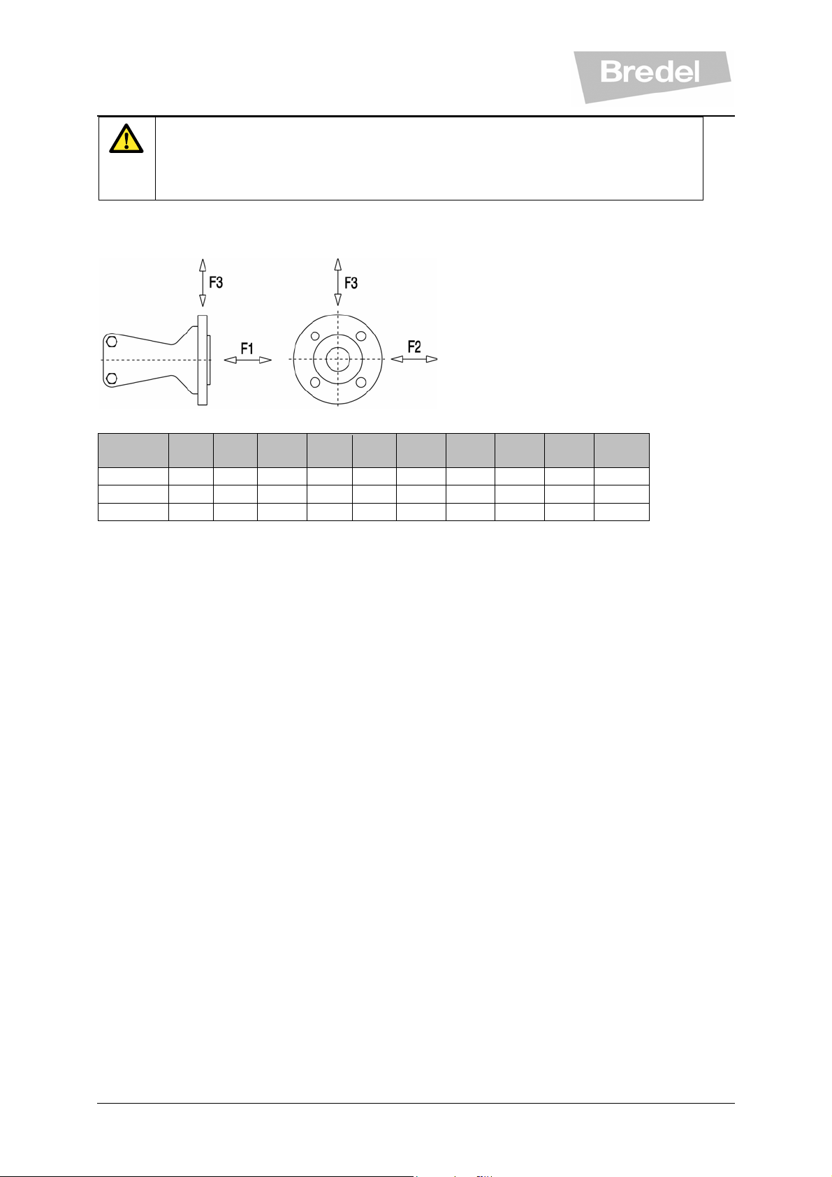
CAUTION
Consider the maximum permissible working pressure on the discharge side.
Exceeding the maximum working pressure may lead to serious damage to the pump.
• Make sure that the maximum forces on the flanges are not exceeded. The maximum
permissible loads on the pump flange are given in the table below:
Force
F1 [N] SP/10 SP/15 SP/20 SP25 SP/32 SP/40 SP/50 SP/65 SP/80 SP/100
F1 600 600 600 1000 1000 1000 1400 1400 2000 2000
F2 120 120 120 200 200 200 300 300 400 400
F3 300 300 300 500 500 500 700 700 1000 1000
5.3.4 Pulsating flow
Hose pumps have a pulsating flow that can result in vibrations of pump and lines under the
following circumstances:
• suction and discharge lines are not fixed correctly
• high pump speed in combination with long suction and discharge lines or high specific
gravity of the product
• diameter of suction and/or discharge line too small
In case of unacceptable pulsations, dampeners for suction and/or discharge line can be
supplied for the pump series SP/25 to SP/100. Please consult your Bredel representative for
literature on Inlet Pulsation Accumulators (IPA) or Pulsation Dampeners (PD). These
accumulators and dampeners are not available for SP/10, SP15 and SP/20.
5.3.5 Pumping pressure (counter pressure)
Should not go over maximum allowance (7,5 bar for SP/10, SP/15 and SP/20; 16 bar for
bigger models). If hose failure looks like explosion, check system for blocked lines, closed
valves or failing pressure relief valves.
5.4 Lifting and moving the pump
For lifting and moving the pumphead, it has been fitted with a lifting strip. This lifting strip is
fitted on the rear of the pumphead. For the weights of the pump, see “Specifications”:
“Weights”, § 10.1.5.
The complete hose pump, i.e. pumphead, gearbox and electric motor, must be lifted using
the lifting eyes in the pump support plus additional support on gearbox and motor using
suitably rated straps or slings, see “Specifications”: Weights, § 10.1.5.
15
Page 16

WARNING
If the pump is to be lifted ensure that all standard lifting practices are
adhered to and carried out by qualified personnel only.
5.5 Placing the pump
Position the pump on a horizontal surface. Use suitable anchor bolts to attach the pump to
the floor surface.
16
Page 17

6 COMMISSIONING
6.1 Preparations
• Connect the electric motor in conformance with the locally applicable rules and
regulations. Have the electrical installation work be carried out by qualified personnel.
• The pump casing is filled to half way level with a specially compounded hose
lubricant. If necessary refill Bredel lubricant via the breather/vent plug (also see:
“Maintenance”: “Changing lubricant”, § 7.3).
• Check the rotation of the rotor.
• Check that the correct number of shims (series SP/25 to SP/100) corresponds with
your application, see “Specifications”: “Shimming”, § 10.1.7.
• For adjusting the compression force of the hose, see “Maintenance”: “Hose
compression force adjustment (shimming)”, § 7.8.
6.2 Commissioning
• Connect the pipework. Make sure that there are no obstructions such as closed
valves.
• Switch on the hose pump.
• Check the rotation of the rotor.
• Check the capacity of the hose pump. If the capacity differs from your specification,
follow the instructions in chapter 9 “Troubleshooting” or consult your Bredel
representative.
• Check the hose pump in accordance with points 1 to 4 of the maintenance table from
section “Maintenance and periodic inspections”, § 7.1.
17
Page 18

7 MAINTENANCE
WARNING
Only use original Bredel parts when maintaining the hose pump. Bredel cannot
guarantee a correct functioning and any consequential damage that occurs
7.1 Maintenance and periodic inspections
In the diagram below it is indicated which maintenance and periodic inspections need to be
carried out on the hose pump to guarantee an optimal safety, operation and life of the pump.
Point Action To be carried out Remark
from the use of non-original Bredel components, also see: “Safety” and
“Warranties”.
1 Check the lubricant
level
2 Check the pumphead
for any leakage of
lubricant around the
cover and the
flanges.
3 Check pump for
deviating
temperature or
strange noises.
4 Check pressing
shoes for excessive
damage.
5 Internal cleaning of
the pump hose.
6 Replacing pump
hose.
7 Changing lubricant After every 2nd hose
8 Replacing pump
seal.
9 Replacing pressing
shoes.
10 Replacing bearings. If necessary. See “Replacing pressing shoes”.
Before start up of
the pump and on a
scheduled interval
during operation.
Before start up of
the pump and on a
scheduled interval
during operation.
On a scheduled
interval during
operation.
When replacing the
pump hose.
Cleaning of the
system or product
change.
Preventive, this
means after 75% of
the hose life of the
first hose.
change or after
5,000 service hours,
whichever comes
first or after hose
rupture.
If necessary. See “Replacing seal ring, bearings and wear
Wear on the running
surface.
Make sure that the pump casing is filled to half
way level with a specially compounded hose
lubricant. If necessary refill the lubricant (also
see “Maintenance”: “Changing lubricant”).
See “Troubleshooting”.
See “Troubleshooting”.
See “Replacing pump hose’.
See “Cleaning pump hose”.
See “Replacing pump hose”.
See “Changing lubricant”.
ring”.
See “Replacing pressing shoes”.
18
Page 19

Cleaning pump hose
7.2
With a lot of products it is necessary to have the pump hose cleaned immediately after
pumping to avoid hardening of the product inside. The inside of the pump hose can be easily
cleaned by rinsing the pump with clean water. If a cleaning fluid is added to the water, it must
be checked that the hose liner material is resistant to that. Also note that the pump hose can
resist the cleaning temperature. Special cleaning balls are also available; please consult your
Bredel representative).
7.3 Changing lubricant
• Place a tray under the drain plug (series SP/25 to SP/100) in the cover of the pump.
Remove the drain plug. Catch the lubricant from the pump housing in the tray.
Position the drain plug and tighten it firmly. In case of SP/10, SP/15 and SP/20
pumps: remove the hose and drain via the lower port.
• The pump housing can be filled with lubricant via the breather/vent on the cover. For
this purpose remove the breather cap and position a funnel in the breather. In order
to facilitate the filling with lubricant for the series SP/25 to SP/100 it is advised to
remove one or two bolts in the inspection window. Pour the lubricant in the pump
housing via the funnel.
• Keep on pouring until the lubricant level has risen at approx. half way of the pump
casing, or that the specified quantity has been filled. See “Lubricant” § 10.1.3.
7.4 Changing oil in gearbox
For information regarding the changing of oil in the gearbox and the type of oil to be used we
refer to the documentation of the manufacturer of this item.
7.5 Replacing pump hose
7.5.1 Hose removal
The pump hose can be changed without removing the pump cover. If applicable, close the
isolation valves on both the inlet and discharge of the pump to minimize fluid loss.
7.5.2 Removal of lubricant
Place a lubricant tray of sufficient capacity to contain the hose lubricant plus any process
fluid that might be contained within the pump housing. Remove the drain plug (not applicable
for SP/10, SP/15 and SP/20; lubricant will flow when hose is removed) . Ensure that the
breather vent in front is not blocked.
7.5.3 Removal of piping
Shut off the valves on both suction and discharge side and disconnect the piping of both the
ports.
7.5.4 Loosening of hose clamps
Loosen all hose clamps on both suction and discharge ports.
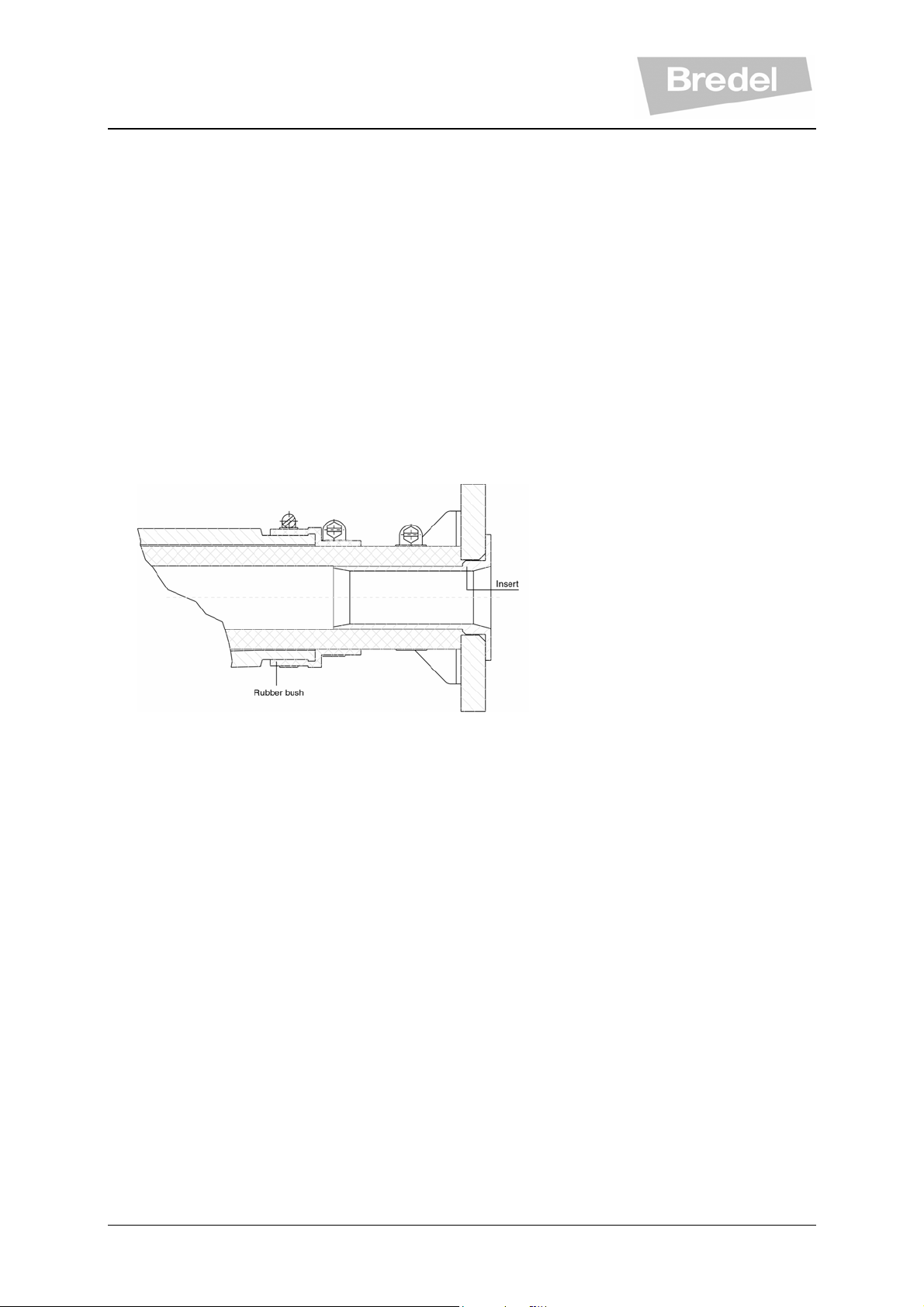
7.5.5 Removal of flanges and/or inserts
Pull the inserts from the hose (SP/10, SP/15 and SP/20) by removing the flanges (SP/25SP/100) on both the suction and discharge port.
19
Page 20
7.5.6 Removal of flange brackets
Remove the flange bracket (SP/25-SP/100) or flange bracket and insert (SP/10, SP/15 and
SP/20) on both suction and discharge port.
7.5.7 Removal of the hose
The hose can be removed without removing the pump cover.
Simply remove the hose by jogging the drive motor.
7.5.8 Cleaning of pump casing
Flush out casing cavity to remove any contaminants. If necessary remove the pump cover to
clean casing completely (but isolate the pump from the electrical supply first).
WARNING
Never remove the pump cover whilst the hose is in place.
The front covers of the series SP/25 to SP/100 should not be removed whilst
the hose is in place. This can cause a deformation of the pump casing and a
non straight tension of the bolts. After fitting the cover and starting up the
pump, the bolts can be extremely forced and break.
When the pump cover was removed for cleaning purposes, refit it before installing the
hose Check the cover O-ring for damage and replace if necessary. Make sure that the bolts
are refitted and that they are tightened in the correct order, diagonally opposite each other,
see “Specifications”: ‘’Torques’’, § 10.1.6.
7.5.9 Tighten drain plug (not applicable for SP/10, SP/15 and SP/20)
Before the hose can be loaded the drain plug has to be mounted. Make sure that the drain
plug is mounted in such a way that no leakage of lubricant can occur.
7.5.10 Preparation of pump hose
Clean the outside of the pump hose and thoroughly lubricate the external surface of the hose
with the Bredel hose lubricant.
7.5.11 Insertion of the hose
• Switch on the electrical supply again and insert the hose into the upper port.
• Jog the drive motor to feed the hose through the housing.
• If necessary, help by pressing the hose firmly into the port opening.
• Stop the drive when the hose is equally extended from the ports.
7.5.12 Place hose clamps
Place on both the suction and discharge port the bushes, all hose clamps (do not tighten
yet!), the brackets, the flanges and the inserts.
7.6 Hose connection
Note: Always start hose connection at one port and finalize these actions completely. Then
repeat these actions for the other port. In this instruction we start from the suction port.
20
Page 21
7.6.1 Mount flange brackets (SP/25 to SP/100)
• Mount the flange brackets on the suction port by replacing the bolts.
• Do not tighten the bolts at this stage!
• Mount the flange and the insert
• Mount the suction line
7.6.2 Positioning of pump hose
Jog the motor in the direction of the suction port to drive the hose against the flange face.
Ensure that the hose butts up against the flange face and that the insert is seated correctly.
7.6.3 Tighten hose clamps
• Tighten all the hose clamps.
• Make sure that hose clamp is mounted directly against the vertical part of the rubber
bush.
Now repeat step 7.6.1 to 7.6.3 for the discharge port
7.6.4 Tighten bolts of all flange brackets
Now tighten the bolts of all flange brackets.
7.6.5 Filling with lubricant
• Remove one screw from the inspection window (not applicable for SP/10, SP/15 and
SP/20) to vent the pump housing.
• Add lubricant until ½ of the pump housing is filled. See “Specifications”, “Lubricant”,
§ 10.1.3 for the required quantity of lubricant per pump type.
7.6.6 Finally
• Replace removed bolt(s) in inspection window (not applicable for SP/10, SP/15 and
SP/20).
• Open the suction and discharge valves.
•
Switch on the electrical supply.
21
Page 22
CAUTION
When the pressing shoes are worn the compression force of the hose could
decrease. If the compression force is too low, this results in a loss of capacity
by the backflow of the liquid to be pumped. Backflow results in a reduction of
the life of the pump hose.
7.7 Exchanging replacement parts
7.7.1 Replacing pressing shoes (not applicable for SP/10, SP/15 and SP/20)
• Remove the pump hose and cover. See paragraph 7.5.1 through 7.5.8
• Loosen the retaining bolt(s) of the pressing shoe a few turns. Remove the shims.
• Loosen the retaining bolt(s) of pressing shoe completely and remove the pressing
shoe.
• Fit the eventually removed shims again. Position the (new) pressing shoe, tighten
the retaining bolt(s), see “Specifications”: “Torques”, § 10.1.6.
• Repeat the procedure for removing and fitting the second pressing shoe by
repeating above mentioned steps.
WARNING
Never remove the pump cover whilst the hose is in place.
The front covers of the series SP/25 to SP/100 should not be removed whilst
the hose is in place. This can cause a deformation of the pump casing and a
non straight tension of the bolts. After fitting the cover and starting up the
pump, the bolts can be extremely forced and break.
• Check the cover O-ring for damage and replace if necessary. Refit the cover. Make
sure that the bolts are refitted and that they are tightened in the correct order,
diagonally opposite each other, see “Specifications”: ‘Torques”, § 10.1.6.
• Switch on the electrical supply.
• Replace hose and refill the lubricant, see paragraph 7.5.9 through 7.6.5
7.7.2 Replacing seal and bearings
• Remove the pump hose and cover, see paragraph 7.5.1 through 7.5.8
• Isolate the pump from the electrical supply.
• Loosen coupling on drive end of shaft.
• Remove rotor retaining ring and pull rotor off shaft.
• Remove bearing cover for SP/25 to SP/100, or joint ring and safety ring for SP/10,
SP/15 and SP/20.
• Pull shaft assembly out at rotor side.
• Use arbor press and V-block to remove both bearings from shaft. Use file to deburr
key ways.
• Remove lip seals from housing and bearing cover. It is recommended to replace
seals whenever shaft has been removed.
22
Page 23

• Pre-grease bearings with lithium grease.
• Use arbor press and press new bearings on shaft. Coat shaft areas with anti-seize
compound to facilitate assembly.
• Press oil seal into housing.
• Insert joint ring into bearing cover groove.
• Press shaft assembly into housing.
• Add grease through grease fitting and fill housing cavity until grease is forced through
the exposed front bearing. Then take away grease nipple and plug the hole.
• Assemble bearing cover to housing to secure shaft assembly for SP/25 to SP/100.
Assemble safety ring and press in joint ring for SP/10, SP/15 and SP/20.
• Place rotor key and assemble rotor. Secure with retainer ring.
• Check the cover O- ring for damage and replace if necessary. Refit the cover. Make
sure that the bolts are refitted and that they are tightened in the correct order,
diagonally opposite each other, see “Specifications”: ‘Torques”, § 10.1.6.
• Switch on the electrical supply to the pump.
• Fit the (new) pump hose, see 7.5.9 through 7.6.5
7.8 Hose compression force adjustment (shimming) (not applicable for SP/10, SP/15
and SP/20).
Fitting and removing shims is a simple action which can be carried out via the inspection
window on the front of the pump housing. The pump hose or the pump cover does not need
to be removed. In order to determine the correct number of shims for your specific
application see “Specifications”: “Shimming”, § 10.1.7.
CAUTION
Too many shims, this means a too high compression force on the pump hose,
will create a too high load of the pumphead and pump hose, which may result in
a reduction of the life of the pump hose. Too few shims, this means a to low
compression force on the pump hose, create a loss of capacity and backflow.
Backflow results in a reduction of the life of the pump hose.
• Jog the motor until the pressing shoe is positioned in view of the inspection window.
• Isolate the pump from the electrical supply.
• Loosen the retaining bolts of the inspection window and remove the bolts.
• Remove the inspection window. Care must be taken not to damage the gasket.
• Loosen the retaining bolt(s) of the pressing shoe a few turns.
• Fit the shims or remove them until the correct number of shims is present (see
“Specifications”: “Shimming”, § 10.1.7). To aid in assembly, preform shim around
rotor. Then insert with slot oriented around bolt.
• Fasten the retaining bolt(s) of the pressing shoe with the correct torque (see
“Specifications”: “Torques”, § 10.1.6).
CAUTION
When maximum suction capability is required, the pump shimming must be as
for minimum 5 bar counter pressure at corresponding speed.
23
Page 24

• Refit the inspection window. Check the gasket for damage and replace if necessary.
Make sure that all bolts are refitted and that they are tightened in the correct order,
diagonally opposite each other, see “Specifications”: “Torques”, § 10.1.6.
• Switch on the electrical supply.
7.9 Fitting options
7.9.1 Fitting a high-level float switch
• Note: in case of series SP/10, SP/15 and SP/20 another type of cover is required.
• Dismount the standard breather on the cover of the pump
• Slide the standard breather cap from breather.
• Replace the standard breather cap with the breather cap with high level float switch
and slide it over breather.
• Mount the breather on the cover of the pump.
• Connect the high-level float switch to the electrical supply. Bear in mind that the
electrical contact of the float switch is normally closed (NC). When the lubricant level
is (too) high the contact will open.
7.9.2 Fitting a low level float switch (not applicable for SP/10, SP/15 and SP/20)
• If the pump is filled with lubricant this must be removed first. Place a tray under the drain
plug in the desaeration pipe on the cover of the pump. Remove the drain plug. Catch
the lubricant from the pump housing in the tray.
• Replace the drain plug by a low level floater.
• Connect the low level float switch to the electrical supply. Bear in mind that the
electrical contact of the float switch is normally closed (NC). This means that: the
contact of the low level float switch opens at a (too) low lubricant level.
• Make sure the lubricant returns to the prescribed level, see: “Maintenance”:
“Changing lubricant”, § 7.3.
24
Page 25

8 STORAGE
8.1 Hose pump
Store the hose pump or pump parts in a dry area. Make sure that the hose pump or pump
parts are not exposed to temperatures lower than - 40 °C or higher than + 70 °C.
Cover the openings of the inlet and outlet ports.
Prevent corrosion of untreated parts. For this purpose use the correct protection or
packaging means.
After a long period of standstill or storage, the static load on the pump hose may have
caused permanent deformation, which will reduce the life of the pump hose.
8.2 Pump hose
Store the pump hose in a cool and dark room. Pump hoses have a limited storage life. After
2 years the hose material will age, which will reduce the life of the hose.
25
Page 26

9 TROUBLESHOOTING
If the hose pump does not function (correctly), consult the following checklist to see if you
can remedy the error yourself. If this is not the case, please contact your Bredel
representative.
Problem Possible Cause Correction
Failure to operate
High pump temperature.
Low capacity/pressure
Stalled rotor Check that the pump is stalled by
Lubricant level monitoring system
has been activated.
Non standard hose lubricant used. Consult the Bredel representative for the
Low lubricant level. Add Bredel lubricant, see for the required
Product temperature too high. Consult the Bredel representative about
Internal friction on the hose caused
by blocked or poor suction
characteristics.
Over-shimming of the pump rotor
shoes (not for SP/10, SP/15 and
SP/20)
High pump speed. Reduce pump speed to a minimum.
Shut-off valve in the suction line
(partly) closed.
Check that the supply power switch is on. No voltage
Check the electrical supply is available at
the pump.
incorrect fitting of the hose.
Check that the lubricant level monitoring
system has stalled the pump. Check the
functioning of the lubricant level
monitoring system, or check the lubricant
level.
correct lubricant.
amount of lubricant “Maintenance”:
“Changing lubricant”.
the maximum temperature range of the
product.
Check pipework/valves for blockages.
Ensure that the suction pipework is as
short as possible and that the diameter is
large enough.
Consult the diagram, see “Specifications”:
“Shims specifications”. Remove excess
shims.
Consult with your Bredel pump
representative for advice on optimum
pump speeds.
Fully open the valve.
Under shimming of the pressing
shoes.
Hose rupture or badly worn hose Replace hose, see “Maintenance”:
(Partial) blockage of the suction line
or too little product on the suction
side.
Consult the diagram (see “Specifications”:
“Shims specifications”. Fit the correct
number of shims.
“Replacing pump hose”.
Ensure that the suction line is clear of
blockages and that sufficient product is
available.
26
Page 27

The filling degree of the pump hose
is too low, because the speed is too
high in relation to the viscosity of the
product to be pumped and the inlet
pressure. The suction line can be too
long or too narrow or a combination
of these factors.
Consult your Bredel representative for a
recommendation.
Vibration of the pump and
pipework.
Broken front cover bolts Pump cover (dis)mounted with the
Short hose life.
Hose pulled into the pump.
Suction and discharge lines are not
secured correctly.
High pump speed with long suction
and discharge lines or high product
specific gravity or a combination of
these factors.
Too narrow diameter of suction
and/or discharge line
hose in the pump
Chemical attack of the hose. Check the compatibility of the hose
High pump speed. Reduce pump speed.
High discharge pressures. Maximum working pressure 16 bar.
High product temperature. Consult your Bredel representative for
High pulsations. Restructure the discharge and inlet
Insufficient or no hose lubricant in
the pumphead.
Check and secure pipework.
Reduce pump speed. Reduce the line
lengths on both suction and discharge
where possible. Consult your Bredel
representative for a recommendation.
Increase the diameter of the
suction/discharge lines.
Never (dis)mount the pump cover when
the hose is still in the pump
material with the product to be pumped.
Consult your Bredel representative for
correct hose selection.
Check that the discharge line is not
blocked, the shut-off valves are fully
opened and the pressure relief valve
functions properly (if present in the
discharge line).
correct hose selection.
conditions.
Add extra lubricant, see “Maintenance”:
“Changing lubricant”.
No original Bredel lubricant. Consult the Bredel representative for the
correct lubricant.
Extremely high inlet pressure - larger
than 300 Kpa.
Lubricant leakage at flange
bracket.
Hose blocked by an incompressible
object in the hose. The hose cannot
be compressed and will be pulled
into the pump housing.
Bolts of flange bracket loose. Tighten to the specified torque settings
Bolts of hose clamps loose. Tighten to the specified torque settings
Reduce the inlet pressure.
Remove hose, check for blockages and
replace if necessary.
(see ‘Torques’).settings, see
“Specifications”: “Torques”.
(see ‘Torques’).settings, see “Torques”.
27
Page 28

10 SPECIFICATIONS
10.1 Pumphead
10.1.1 Performance
Description SP/10 SP/15 SP/20 SP/25 SP/32 SP/40 SP/50 SP/65 SP/80 SP/100
Max. capacity, continuous
[m3/h]
Max. capacity,
intermittently [m3/h] ◊
Capacity per revolution
[l/rev]
Max. permissible
discharge pressure [kPa]
Permissible ambient
temperature [°C]
Permissible product
temperature [°C]
Sound level on 1m
[dB(A)]
◊ Intermitted duty: “Let the pump stand still to cool down for at least 1 hour after 2 hours of operation”.
10.1.2 Materials
0,11 0,38 0,62 1,80 3,25 6,0 10,5 20,0 28,0 36,0
0,16 0,60 1,09 2,88 5,25 9,6 17,5 32,0 42,0 60,0
0.022 0,083 0,152 0,30 0,625 1,33 2,9 6,7 11,7 20,0
750 750 750 1600 1600 1600 1600 1600 1600 1600
- 20 to + 45
- 10 to + 80
60 60 60 70 70 70 70 70 70 70
Description
Pump housing
Cover
Pump rotor
Pressing shoe
Pump support Mild steel, galvanized
Flange bracket Mild steel, galvanized
Mounting material of pump cover Mild steel, galvanized
Mounting material of pump
support
Seals Nitrile
Bush Neoprene
Cast-iron
SP/10, SP/15: synthetic
optional: mild steel
SP/20 to SP/100: steel
Cast-iron
Aluminum (not applicable for SP/10, SP/15 and
SP/20)
Mild steel, galvanized
Material
10.1.3 Lubricant
Required quantity of lubricant [Liters]
SP/10 SP/15 SP/20 SP/25 SP/32 SP/40 SP/50 SP/65 SP/80 SP100
0,25 0,50 0,50 2 3 5 10 20 40 60
28
Page 29

10.1.4 Surface treatment
The pumphead is provided with a two component epoxy base coat. After drying the layer
thickness must be at least 30 microns.
Subsequently these components are provided with a two component polyurethane top coat, in
the RAL 5017 colour blue and with a 100% gloss rate. After this coat of paint has dried the layer
thickness must be at least 30 microns.
All galvanized parts, exclusive of mounting articles, have been provided with an electrolytic zinc
layer of 15 –20 microns.
10.1.5 Weights and dimensions
Description Weights and dimensions per pump model
series
Net weight pump
(kg)
Gross weight pump
(kg)
Dimensions crate
(cm)
Cubage (m3)
Dimension pump
hose (mm)
Weight pump hose
(kg)
Quantity lubricant
required (litres)
Weight lubricant (kg)
Weight supports [set]
(kg)
Weight pump shaft
(kg)
Weight rotor (kg)
Weight pressing
shoes [set] (kg)
Weight pump cover
(kg)
Weight pump
housing (kg)
Flange connection,
without inserts [set]
(kg)
Insert [set] (kg)
SP/10 SP/15 SP/20 SP/25 SP/32 SP/40 SP/50 SP/65 SP/80 SP/100
10 19 19 59 85 139 195 395 600 955
10 19 19 80 125 175 265 450 680 1055
30x26x
10x31x
37x32x
27
- - - 0,222 0,35 0,42 0,65 1,12 1,71 2,64
15x36x
510
0,35 0,70 0,70 2 3 3,80 6,40 11,50 21 31
0,25 0,50 0,50 2 3 5 10 20 40 60
0,30 0,60 0,60 2,5 3,6 6 13 26 52 78
0,75 1,60 1,60 17 24 43 56 50 92 160
0,50 0,90 0,90 2 5 5 9,50 18 39 53
0,75 2,50 2,50 4 8 12 24 44 69 108
- - - 0,70 1,10 2 2,50 5 8 13
0,2 0,65 0,65 7 10 16 24 54 89 123
5,70 10,7 10,7 21 40 50,50 82 170 238 390
1,47 1,72 1,90 2,98 4,26 4,88 6,38 7,80 11,4 14,9
0,04 0,05 0,07 0,13 0,18 0,34 0,46 3,13 4,06 5,69
28
755
37x32x
28
19x36x
755
72x56x
55
25x53x
1005
87x62x
65
32x61x
1250
87x76x
63
40x66x
1490
106x
90x68
50x80x
1820
127x
105x
65x99x
2335
84
148x
124x
93
80x
120x
2780
170x
145x
107
100x
144x
3275
29
Page 30

10.1.6 Torques
Description Torques in [Nm] per pump type
SP/10 SP/15 SP/20 SP/25 SP/32 SP/40 SP/50 SP/65 SP/80 SP/100
Pressing
shoe
Cover 3,5 3,5 10 25 50 50 50 50 50 85
Inspection
window
Hose clamp 2 2 2 12 12 12 12 12 12 12
Rubber bush
clamp
Flange
bracket
Support 25 25 25 50 85 85 85 210 410 710
- - - 30 40 120 160 160 160 160
- - - 1,75 1,75 1,75 1,75 1,75 3,5 3,5
1,75 1,75 1,75 1,75 1,75 1,75 1,75 1,75 1,75 1,75
10 10 10 25 50 50 50 85 210 210
30
Page 31

10.1.7 Shimming
31
Page 32
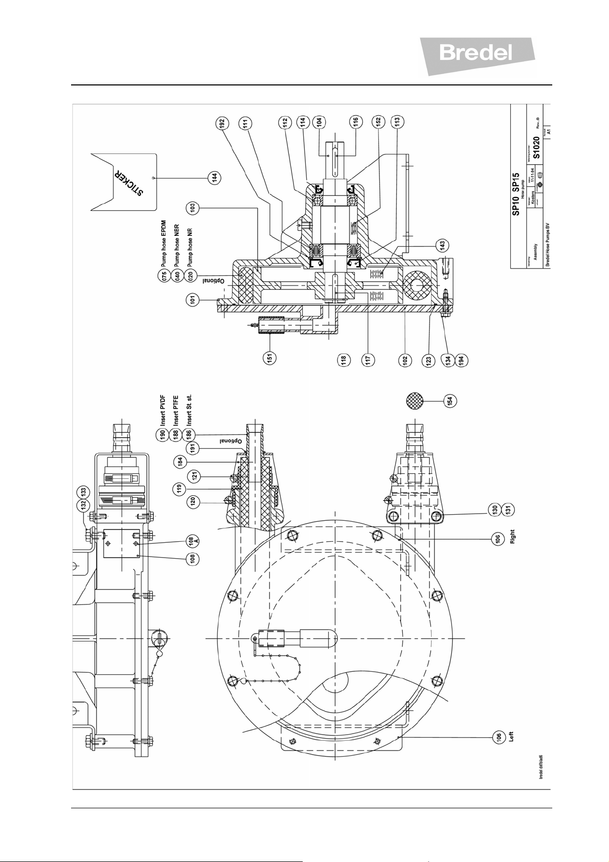
10.1.8 Parts list: SP/10-SP/15
32
Page 33

Parts list: SP/10-SP/15
Pos Pcs Description SP/10 SP/15
101 1 Pump housing 010101 015101
102 1 Pump cover 010102 015102
103 1 Rotor 010103 015103
104 1 Pump shaft 010104 015104
106R 1 Mounting support Right 010106R 015106R
106L 1 Mounting support Left 010106L 015106L
108 1 Name tag Z010108 Z015108
108A 2 Pin screw F419001 F419001
111 1 Cylinder roller bearing B220520 B220620
112 1 Deep groove ball bearing B140500 B140600
113 1 Joint ring S240240 S240290
114 1 Oil seal S210240 S210290
116 1 Drive key F436055 F436055
117 1 Rotor key F436052 F436076
118 1 Snap ring F343017 F343022
119 2 Rubber bush 010119 015119
120 2 Hose clip C111508 C111510
121 2 Hose clip C111506 C111508
123 1 O-ring S121641 S121771
130 8 Hexagon screw F111038 F111038
131 8 Spring washer F531008 F531008
132 4 Hexagon screw F111071 F111071
133 4 Spring washer F336011 F336011
134 8 Hexagon screw F111040 F111040
143 1 Lubricant 901143 901143
144 1 Sticker "Caution" 29082235 29082235
151 1 Air breather cap 29040223 29040223
152 0,04 Kg Grease Z010152
152 0,06 Kg Grease Z010152
153 1 Screw F401097 F401097
154 1 Cleaning sponge 010154 015154
184 2 Insert retaining flange 010184 015184
186 1 Insert stainless steel 010186 015186
188 1 Insert Teflon/PTFE 010188 015188
190 1 Insert PVDF 010190 015190
191 2 Circlips F543013 F543017
192 1 Circlips F344044 F344052
194 8 Washer F326005 F326005
33
Page 34
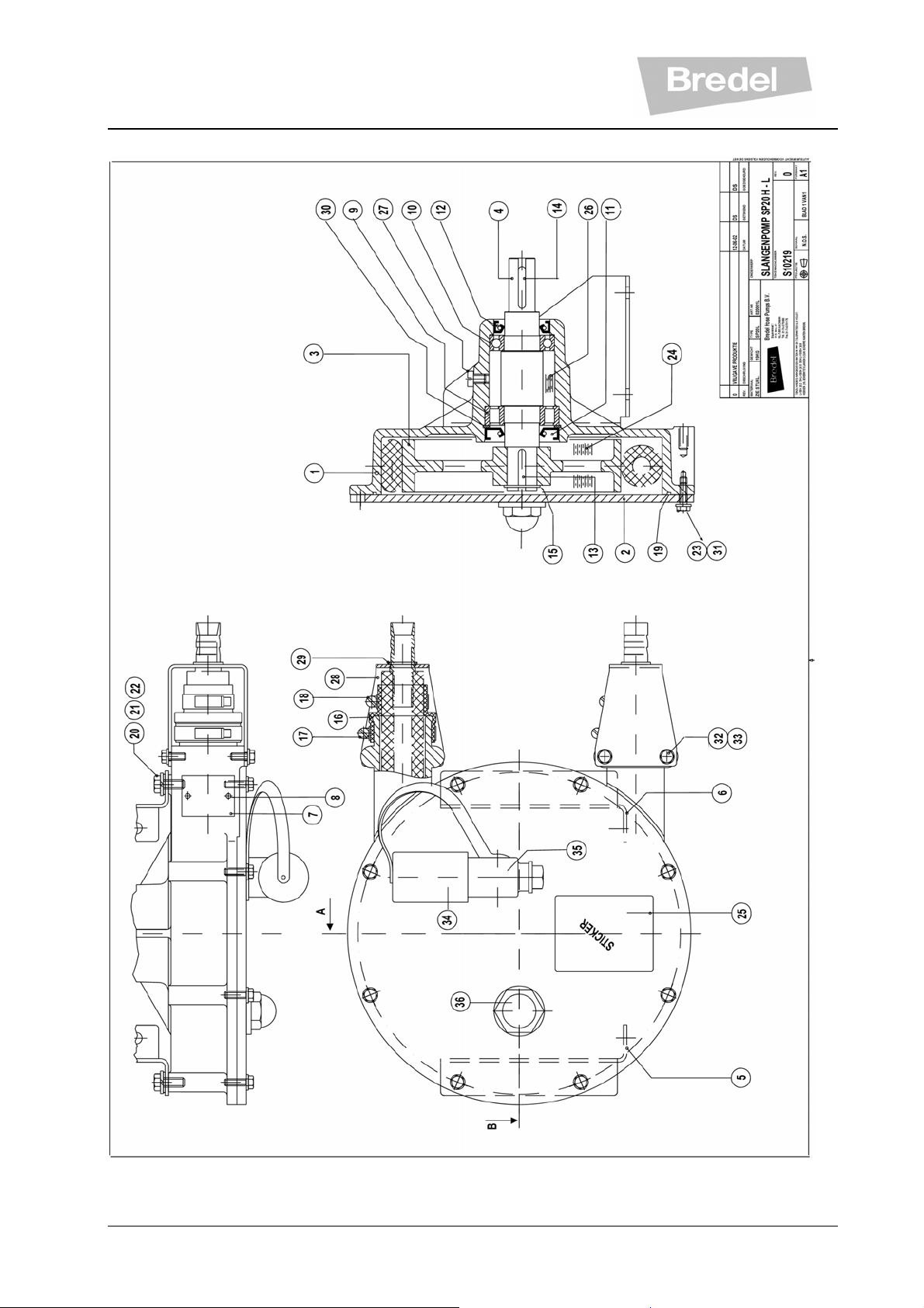
10.1.9 Parts list: SP/20 H-L
34
Page 35

Parts list: SP/20 H-L
Pos Pcs Description SP/20 H SP/20 L
1 1 Pump housing 15101 15101
2 1 Pump cover 015102STD 015102STD
3 1 Rotor 020103H 020103L
4 1 Pump shaft 15104 15104
5 1 Mounting support
015106R 015106R
Right
6 1 Mounting support Left 015106L 015106L
7 1 Name tag Z020108H Z020108L
8 2 Pin screw F419001 F419001
9 1 Cylinder roller bearing B220620 B220620
10 1 Deep groove ball
B140600 B140600
bearing
11 1 Joint ring S240290 S240290
12 1 Oil seal S210290 S210290
13 1 Drive key F436055 F436055
14 1 Rotor key F436076 F436076
15 1 Snap ring F343022 F343022
16 2 Rubber bush 15119 15119
17 2 Hose clip C111510 C111510
18 2 Hose clip C111508 C111508
19 1 O-ring S121771 S121771
20 4 Hexagon screw F111071 F111071
21 4 Spring washer F336011 F336011
22 4 Plain washer F322012 F322012
23 8 Hexagon screw F111040 F111040
24 0,5 L Lubricant 901143 901143
25 1 Sticker "Caution" 29082235 29082235
26 0,06 Kg
Grease
Z010152 Z010152
27 1 Hexagon screw F401097 F401097
28 2 Insert retaining flange W015184 W015184
29 2 Snap ring F543019 F543019
30 1 Snap ring F344052 F344052
31 8 Spring washer F336009 F336009
32 8 Hexagon screw F111038 F111038
33 8 Spring washer F336009 F336009
34 1 Air breather cap
29065223 29065223
35 1 Bend, 90 º 29011242 29011242
36 1 Cat eye 29036274 29036274
35
Page 36
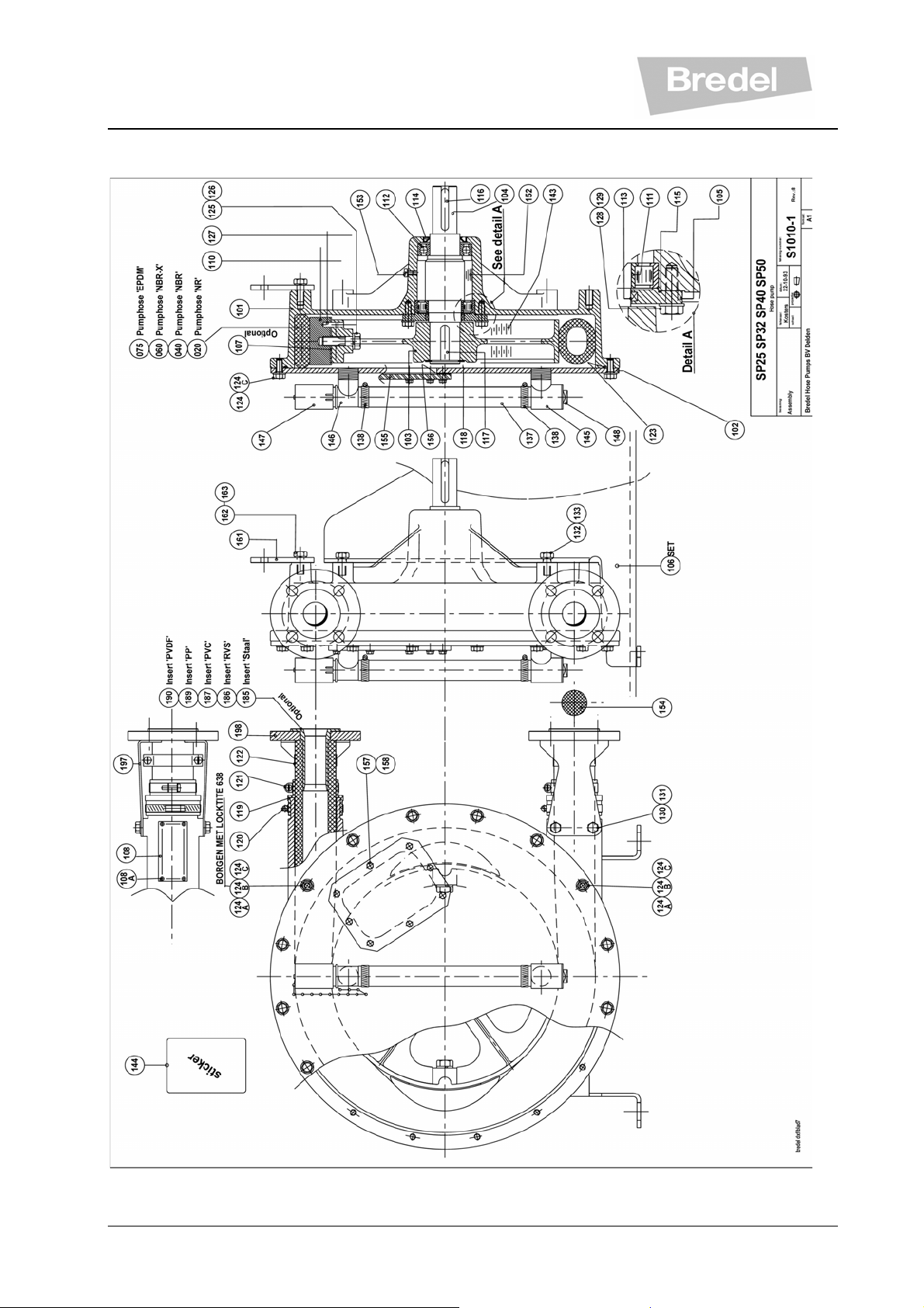
10.1.10 Parts list: SP/25, SP/32, SP/40 and SP/50
36
Page 37

Parts list: SP/25, SP/32, SP/40 and SP/50
Pos Pcs Description SP/25 SP/32 SP/40 SP/50
101 1 Pump housing 025101 032101 040101 050101
102 1 Pump cover 025102 032102 040102 050102
103 1 Rotor 025103 032103 040103 050103
104 1 Pump shaft 025104 9298104 9298104 050104
105 1 Bearing cover 025105 9140105 9140105 050105
106R 1 Mounting support Right 025106R 032106R 040106R 050106R
106L 1 Mounting support Left 025106L 032106L 040106L 050106L
106B 1 Mounting support 025106B 032106B 040106B 050106B
106S 1 Mounting support - - 040106S 050106S
107 14 Shim 025107
107 10 Shim 032107
107 16 Shim 040107
107 20 Shim 050107
108 1 Name tag Z025108 Z032108 Z040108 Z050108
108A 4 Pin screw F419001 F419001 F419001 F419001
110 2 Pressing shoe 025110 032110 040110 050110
111 1 Cylinder roller bearing B220820 B221120 B221120 B221420
112 1 Deep groove ball bearing B150700 B151000 B151000 B151200
113 1 Joint ring S200400 S200550 S200550 S200700
114 1 Oil seal S210350 S210500 S210500 S210600
115 1 O-ring S120411 S120441 S120441 S121571
116 1 Drive key F436084 F436128 F436128 F436148
117 1 Rotor key F436101 F436901 F436901 F436902
118 1 Snap ring F343032 F343043 F343043 F343053
119 2 Rubber bush 025119 032119 040119 050119
120 2 Hoseclip C111512 C111513 C111513 C111515
121 2 Hoseclip C121006 C121008 C121010 C121014
122 2 Hoseclip C122005 C122005 C122007 C122009
123 1 Rubber cord for cover 025123 032123 040123 050123
124 10 Hexagon screw F111071 F111096
124 14 Hexagon screw F111096
124 16 Hexagon screw F111096
124A 2 Screw with cuppoint - F429014 F429014 F429014
124B 2 Hexagon nut - F301007 F301007 F301007
124C 10 Plain washer F322012 F322013 F322013 F322013
125 2 Hexagon bolt F111096 F111134 F111186 F101173
126 2 Spring washer F336012 F336013 F336015 F336017
127 2 Pin F415083 F415083 F415083 F415112
128 4 Hexagon screw F111073 F111098 F111098 F111098
129 4 Spring washer F336011 F336012 F336012 F336012
130 8 Hexagon screw F111069 F111093 F111093 F111093
131 8 Spring washer F336011 F336012 F336012 F336012
132 4 Hexagon screw F111096 F111130 F111130 F111130
37
Page 38

Pos Pcs Description SP/25 SP/32 SP/40 SP/50
133 4 Spring washer F336012 F336013 F336013 F336013
137 1 PVC Hose 025137 032137 040137 050137
138 2 Hose clip C111506 C111506 C111506 C111506
143 1 Lubricant 902143 908143 903143 904143
144 1 Sticker "Caution" 29082235 29082235 29082235 29082235
145 1 T with hose nipple 29010241 29010241 29010241 29010241
146 1 Desaeration pipe with
29010242 29010242 29010242 29010242
hose nipple
147 1 Air breather cap 29065223 29065223 29065223 29065223
148 1 Drain plug A131008 A131008 A131008 A131008
152 0,14 Kg Grease Z010152
152 0,29 Kg Grease Z010152 Z010152
152 0,59 Kg Grease Z010152
153 1 Screw F401097 F401097 F401097 F401097
154 1 Cleaning sponge 025154 032154 040154 050154
155 1 Inspection window 025155 032155 040155 050155
156 1 Gasket 025156 032156 040156 050156
157 8 Hexagon Screw F111038 F111040 F111040 F111040
158 8 Washer F322009 F322009 F322009 F322009
161 1 Eye bolt - 09100161 09100161 09100161
162 1 Hexagon screw - F111130 F111130 F111130
163 1 Spring washer - F336013 F336013 F336013
197 4 Flange bracket 025197 032197 040197 050197
198 2 Flange steel 025198 032198 040198 050198
Option 1 Floater in desaeration pipe 29104610 29104610 29104610 29104610
Option 1 Floater in drain plug 29104611 29104611 29104611 29104611
38
Page 39
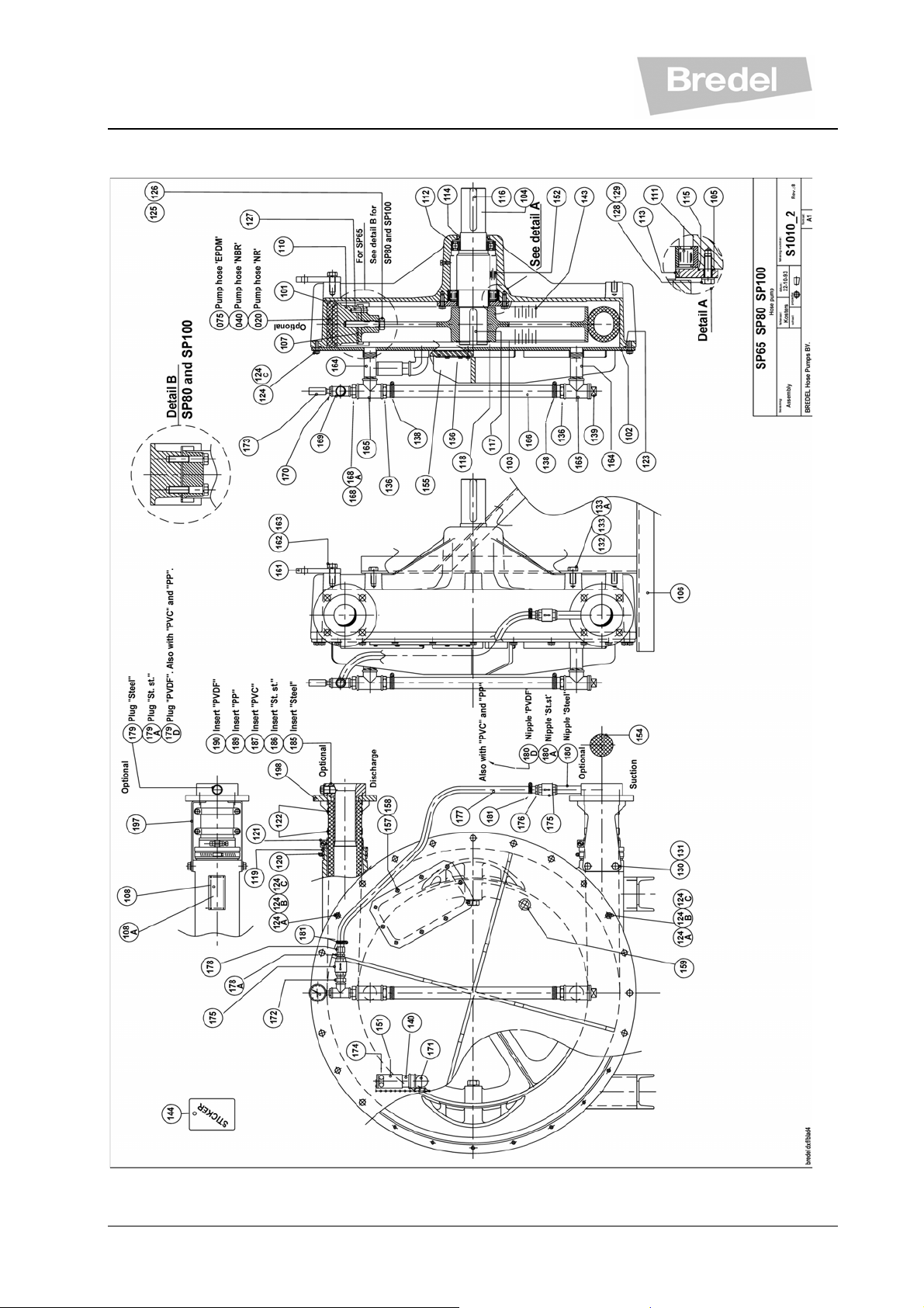
10.1.11 Parts list: SP/65, SP/80 and SP/100
39
Page 40

Parts list: SP/65, SP/80 and SP/100
Pos Pcs Description SP/65 SP/80 SP/100
101 1 Pump housing 065101 080101 100101
102 1 Pump cover 065102 080102 100102
103 1 Rotor 065103 080103 100103
104 1 Pump shaft 065104 080104 100104
105 1 Bearing cover 065105 080105 100105
106 2 Mounting support 065106
106
106
1 Mounting support - Right 080106R 100106R
1 Mounting support - Left - 080106L 100106L
107 24 Shim 065107 080107
107 28 Shim 100107
108 1 Name tag Z065108 Z080108 Z100108
108A 4 Pin screw F419001 F419001 F419001
110 2 Pressing shoe 065110 080110 100110
111 1 Cylinder roller bearing B221720 B222020 B222420
112 1 Deep groove ball bearing B151500 B151800 B152100
113 1 Joint ring S200850 S201000 S201200
114 1 Oil seal S210750 S210900 S211050
115 1 O-ring S121621 S121671 S121721
116 1 Drive key F436173 F436180 F436186
117 1 Rotor key F436903 F436904 F436905
118 1 Snap ring F343061 F343068 F343115
119 2 Rubber bush 065119 080119 100119
120 2 Hose clip C111516 C111517 C111518
121 2 Hose clip C121020 C121025 C121028
122 4 Hose clip C122014 C122019
122 6 Hose clip C122024
123 1 Rubber cord for cover 065123 080123 100123
124 22 Hexagon screw F111098
124 26 Hexagon screw F111098
124 28 Hexagon screw F111130
124A 2 Screw with cup point F429014 F429014 F429024
124B 2 Hexagon nut F301007 F301007 F301008
124C 24 Plain washer F322013
124C 28 Plain washer F322013
124C 32 Plain washer F322015
125 2 Hexagon bolt F101175
125 4 Hexagon bolt F101175 F101175
126 2 Spring washer F336017
126 4 Spring washer F336017 F336017
127 2 Pin F415112 - -
Pos Pcs Description SP/65 SP/80 SP/100
40
Page 41

128 6 Hexagon screw F111100
128 8 Hexagon screw F111100 F111132
129 6 Spring washer F336012
129 8 Spring washer F336012 F336013
130 8 Hexagon screw F111128 F111180 F111180
131 8 Spring washer F336013 F336015 F336015
132 4 Hexagon screw F111182 F111217 F111244
133 4 Spring washer F336015 F336017 F336019
133A 4 Square taper washer - F339005 F339007
136 2 Hose nipple A101018 A103019 A103019
138 2 Hose clip C111506 C111509 C111509
139 1 Drain plug A124006 A124008 A124008
140 1 Pipe nipple 09088140 09100140 09100140
143 1 Lubricant 905143 905143 905143
144 1 Sticker "Caution" 29082235 29082235 29082235
151 1 Air breather cap 09087151 09086151 09086151
152 1,00 Kg Grease Z010152
152 1,55 Kg Grease Z010152
152 3,36 Kg Grease Z010152
153 1 Screw F401097 F401097 F401097
154 1 Cleaning sponge 065154 080154 100154
155 1 Inspection window 065155 09325155 09325155
156 1 Gasket 065156 09325156 09325156
157 10 Hexagon Screw F111042
157 14 Hexagon Screw F111073 F111073
158 10 Washer F322009
158 14 Washer F322012 F322012
159 1 Plug A124006 A124008 A124008
161 1 Eye bolt 065161 080161 100161
162 1 Hexagon screw F111183 F111217 F111244
163 1 Spring washer F336015 F336017 F336019
164 2 Pipe nipple 065164 A127064 A127064
165 2 T 90º A126006 A126008 A126008
166 1 PVC Hose 065166 080166 100166
168 1 Reducing nipple A122013 A122013 A122013
168A 1 Reducing nipple - A122020 A122020
169 1 T 90º A126004 A126004 A126004
170 1 Reducing bush A122005 A122005 A122005
171 1 Bend 90º A128006 A128008 A128008
172 1 Hexagon nipple A121004 A121004 A121004
173 1 Vacuum gauge A220051 A220051 A220051
175 2 Check valve A107002 A107002 A107002
176 1 Hose nipple A101012 A101012 A101012
177 1 PVC Hose 065177 080177 100177
178 1 Hose nipple with nut A102012 A102012 A102012
Pos Pcs Description SP/65 SP/80 SP/100
41
Page 42

178A 1 Hexagon nipple A105004 A105004 A105004
179 1 Plug steel A124004 A124004 A124004
180 1 Pipe nipple steel A127024 A127024 A127024
181 2 Hose clip C111502 C111502 C111502
197 4 Flange bracket 065197 080197 100197
198 2 Flange steel 065198 080198 100198
Option
Option
1
Floater in desaeration pipe 29105610 29124610 29124610
1
Floater in drain plug 29106611 29105611 29105611
42
Page 43

10.1.12 Dimensional drawings
43
Page 44

Dimensional drawings SP/25, SP/32, SP/40 and SP/50
44
Page 45

Dimensional drawings SP/65, SP/80 and SP/100
45
Page 46

10.1.13 EG-Declaration of Conformity
The undersigned,
Company: Bredel Hose Pumps B.V.
Address: P.O. Box 47
City: NL-7490 AA Delden
Country: The Netherlands
Declares as the manufacturer for his own responsibility that the:
Description: Hose pump
Type/mode: SP series
to which this declaration applies, is in conformance with the conditions of the Machine directive
98/37/CE, annexe IIA : 98/37/EC EN60204-1.
If this hose pump is used as an independent pump then the Machine Directive applies.
Responsible person: Hanjo Kruisinga, Managing Director
Company: Bredel Hose Pumps B.V.
Address: P.O. Box 47
City: NL-7490 AA Delden
Country: The Netherlands
Tel.: +31 74 3770000
Fax: +31 74 3761175
Internet:
E-mail:
www.bredel.com
hosepumps@bredel.com
46
Page 47

10.1.14 Manufacturer’s Declaration
The undersigned,
Company: Bredel Hose Pumps B.V.
Address: P.O. Box 47
City: NL-7490 AA Delden
Country: The Netherlands
Declares as the manufacturer for his own responsibility that the:
Description : Hose pump
Type/mode : SP series
to which this declaration applies, is in conformance with the conditions of the Machine
directive 98/37/CE, annexe IIB ; 98/37/EC EN60204-1.
When this pump unit is to be installed into a machine or is to be assembled with other machines
for installations, it must not be put into service until the relevant machinery has been declared in
conformity with this Machinery Directive.
Responsible person: Hanjo Kruisinga, Managing Director
Company: Bredel Hose Pumps B.V.
Address: P.O. Box 47
City: NL-7490 AA Delden
Country: The Netherlands
Tel.: +31 74 3770000
Fax: +31 74 3761175
Internet:
E-mail:
www.bredel.com
hosepumps@bredel.com
47
Page 48
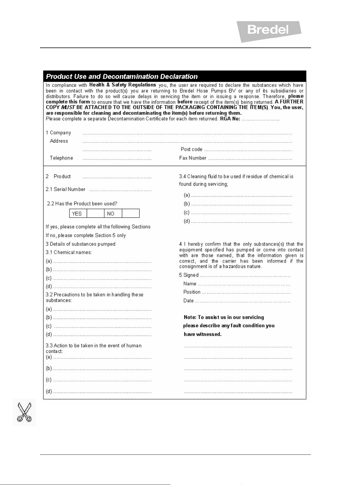
10.1.15 Product Use and Decontamination Declaration
48
Page 49

Bredel Hose Pumps B.V
P.O. Box 47
NL-7490 AA Delden
The Netherlands
Tel.: +31 74 3770000
Fax: +31 74 3761175
hosepumps@bredel.com
www.bredel.com
TS03-058-0
29210390
Member of the Spirax-Sarco Engineering Group
49
 Loading...