

Page 1

Warn Industries, Inc.
12900 S.E. Capps Road
Clackamas, OR USA 97015-8903
1-503-722-1200 FAX: 1-503-722-3000
www.warn.com
Customer Service / Service Clients: 1-800-543-9276
© 2016 Warn Industries, Inc.
WARN®, the WARN logo are registered trademarks of Warn Industries, Inc.
WARN® et le logo WARN sont des marques
déposées de Warn Industries, Inc.
ZEON® Platinum Winch and
Advanced Wireless Remote Control
INSTALLATION AND OPERATOR’S GUIDE
GUIDE D’INSTALLATION ET OPERATEUR
92821A4
Page 2

English .......................................................................... 1
Français ......................................................................25
Español .......................................................................49
92821A4
92821A4
Page 3
Every winching situation has the potential for personal injury. In order to minimize that risk,
it is important to read ALL instructions and safety information regarding your product. Please
familiarize yourself with the operation of your winch before using it and be constantly safety
oriented. These instructions provide important safety information and instructions on how to
install and operate your winch.
In this kit you will find the following pieces of literature:
• Winch Installation Guide/ First Time Operation Instructions
• Product Warranty
SAVE THIS MA NUAL and other product literature for future reference and review frequently
for continuing safe operation.
Instruct all users of this product to review this manual before operating this product.
Additional Product Literature Available Online
:
• Basic Guide to Winching Techniqu es
• Provides a basic understanding of the winch and teaches basics of proper winching
techniques. It is a valuable resource to help winch safely and efficiently.
• Product Specification and Performance Data
• Provides product specifications, performance data and replacement parts information.
• Other product literature specific to some products
Go to
www.warn.com/corporate/literaturerequest.shtml
for additional or replacement
product literature available to view/download.
WARN INDUSTRIES
1
Warn Industries Inc.
12900 SE Capps Road
Clackamas, OR 97015
USA
Customer Service: (800) 543-9 276
International Fax: (503) 722 -3005
Fax: (503) 722-3000
www.warn.com
WARN® and the WARN logo are re gistere d trademar ks of Warn In dustrie s, Inc.
© 2014 Warn Industries, Inc.
ZEON® Platinum Winch and
Advanced Wireless Remote Control
Installation and Operation Guide
TABLE OF CONTENTS:
SAFETY
Symbol Index .......................................................... ............................................................................................................... 3-4
General Safety Precaut ions/FCC & IC Regulations .................................................................................................. .5-8
INSTRUCTIONS
Know Your Winch ................................................................................................... ........................................................... 9-10
Know Your Advanced Wireless Remote Control....................................................... ................................................. 11
Mounting ..................................................................................................................................... .......................................12-13
Electrical Connections ........................................ ................................................................................................................. 14
System Check .................................................................................................................................. ........................................ 14
First Time Operation Instructions ............................................................................................ ..................................15-22
Getting Started ......................................................... .................................................................................................. 15
Home Menu Operat ion ......................................................................................................................................... ...15
Winch Menu Operati on ..................................................................... ................................................................15-18
Auxiliary Menu Operat ion..................................................................................................................................... ..19
Setting Operation ................................................................... .............................................................................20-22
Trouble Shooting/Error Conditions ........................................................... ..................................................................... 23
Final Analysis and Maintenance ................................................................................................................ .....................2 4
WARN INDUSTRIES
2
ORIGIN AL INSTRUC TIONS
92821A4
92821A4
Page 4
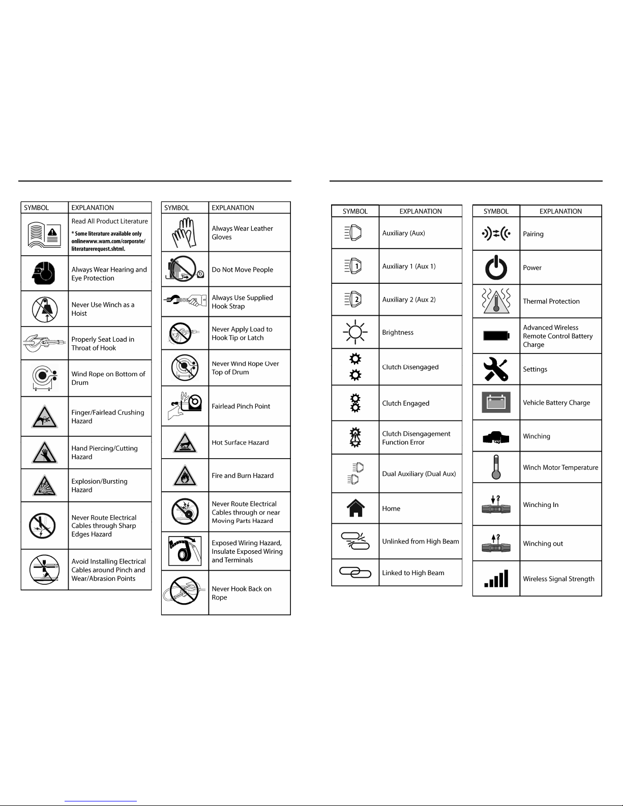
SYMBOL EXPLANATION
Read All Product Literature
* Some literature available only
onlinewww.warn.com/corporate/
literaturerequest.shtml.
Always Wear Hearing and
Eye Protection
Never Use Winch as a
Hoist
Properly Seat Load in
Throat of Hook
Wind Rope on Bottom of
Drum
Finger/Fairlead Crushing
Hazard
Hand Piercing/Cutting
Hazard
Explosion/Bursting
Hazard
Never Route Electrical
Cables through Sharp
Edges Hazard
Avoid Installing Electrical
Cables around Pinch and
Wear/Abrasion Points
SYMBOL EXPLANATION
Always Wear Leather
Gloves
Do Not Move People
Always Use Supplied
Hook Strap
Never Apply Load to
Hook Tip or Latch
Never Wind Rope Over
Top of Drum
Fairlead Pinch Point
Hot Surface Hazard
Fire and Burn Hazard
Never Route Electrical
Cables through or near
Moving Parts Hazard
Exposed Wiring Hazard,
Insulate Exposed Wiring
and Terminals
Never Hook Back on
Rope
WARN INDUSTRIES
3
SYMBOL INDEX
Symbol Index for Winch
WARN INDUSTRIES
4
SYMBOL INDEX
Symbol Index for Advanced Wireless Remote Control
SYMBOL EXPLANATION
Auxiliary (Aux)
1
Auxiliary 1 (Aux 1)
2
Auxiliary 2 (Aux 2)
Brightness
Clutch Disengaged
Clutch Engaged
Clutch Disengagement
Function Error
Dual Auxiliary (Dual Aux)
Home
Unlinked from High Beam
Linked to High Beam
SYMBOL EXPLANATION
Pairing
Power
Thermal Protection
Advanced Wireless
Remote Control Battery
Charge
Settings
Vehicle Battery Charge
Winching
Winch Motor Temperature
Winching In
Winching out
Wireless Signal Strength
92821A4
92821A4
Page 5
FCC Regulation
This device complies with Part 15 of the FCC Rule. Operation is
subject to the following two conditions:
(1) this device may not cause harmful interference, and
(2) this device must accept any interference received,
including interference that may cause undesired operation.
This equipment has been tested and found to comply with the limits
for a Class B digital device, pursuant to part 15 of the FCC Rules. These
limits are designed to provide reasonable protection against harmful
interference in a residential installation. This equipment generates,
uses and can radiate radio frequency energy, and if not installed
and used in accordance with the instructions, may cause harmful
interference to radio communications. However, there is no guarantee
that interference will not occur in a particular installation. If this
equipment does cause harmful interference to radio or television
reception, which can be determined by turning the equipment off
and on, the user is encouraged to try to correct the interference by
one or more of the following measures:
• Reorient or relocate the receiving antenna.
• Increase the separation between the equipment and receiver.
• Connect the equipment into an outlet on a circuit diff erent from
that to which the receiver is connected.
• Consult the dealer or an experienced radio/TV technician for help.
§ 15.21 Information to user.
The users manual or instruction manual for an intentional or
unintentional radiator shall caution the user that changes or
modi cations not expressly approved by the party responsible
for compliance could void the user’s authority to operate the
equipment. In cases where the manual is provided only in a form
other than paper, such as on a computer disk or over the Internet, the
information required by this section may be included in the manual in
that alternative form, provided the user can reasonably be expected
to have the capability to access information in that form.
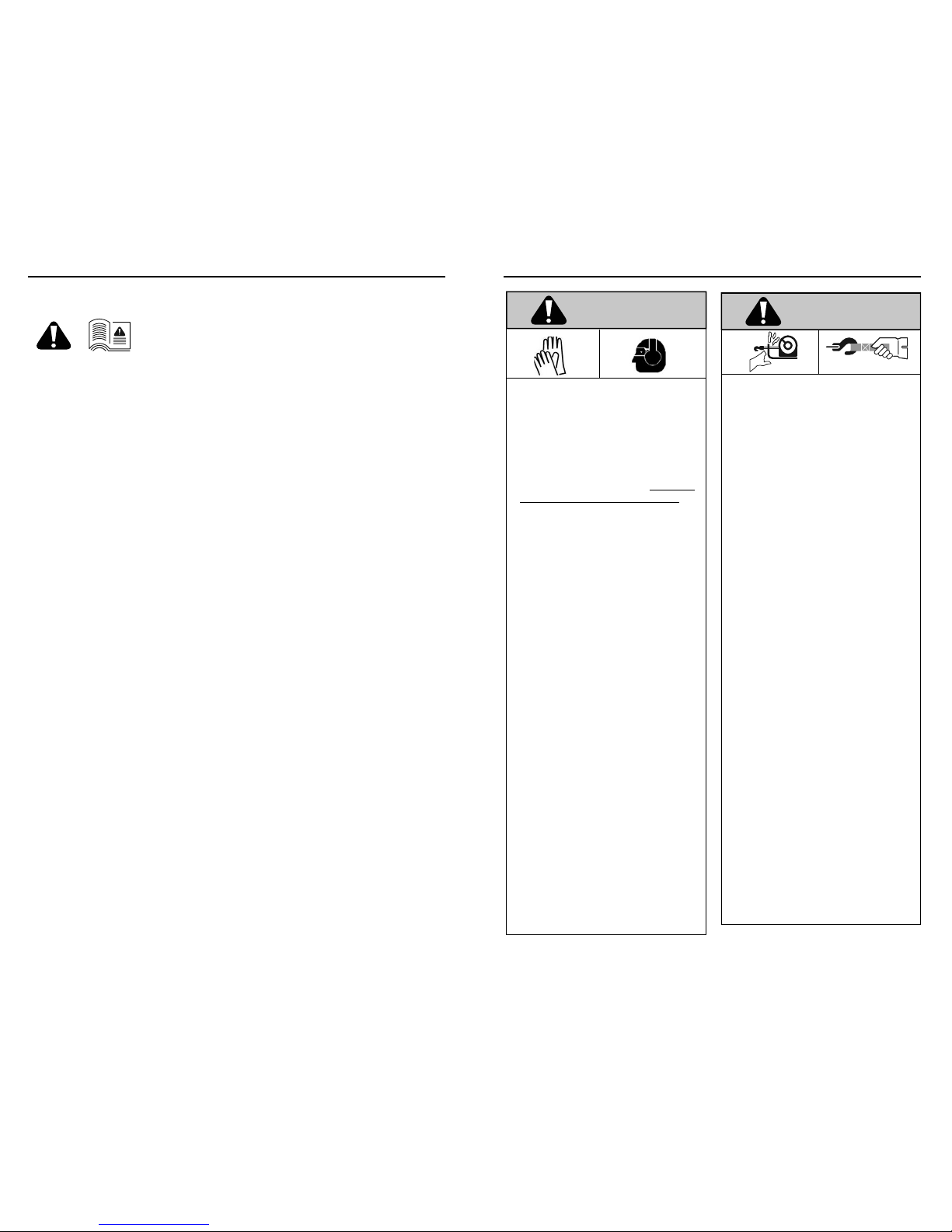
As you read these instructions,
you will see
WARNINGS,
CAUTIONS, NOTICES
and
NOTES
. Each message has a speci c
purpose. WARNINGS are safety messages that indicate a potentially
hazardous situation, which, if not avoided could result in serious
injury or death. CAUTIONS are safety messages that indicate a
potentially hazardous situation which, if not avoided, could result
in minor or moderate injury. A CAUTION may also be used to alert
against unsafe practice. CAUTIONS and WARNINGS identify the
hazard, indicate how to avoid the hazard, and advise of the probable
consequence of not avoiding the hazard. NOTICES are messages to
avoid property damage. NOTES are additional information to help
you complete a procedure.
PLEASE WORK SAFELY!
Warnings and Cautions
Industry Canada
This device complies with Industry Canada license-exempt RSS
standard(s). Operation is subject to the following two conditions:
(1) this device may not cause interference, and
(2) this device must accept any interference, including
interference that may cause undesired operation
of the device.
Under Industry Canada regulations, this radio transmitter may only
operate using an antenna of a type and maximum (or lesser) gain
approved for the transmitter by Industry Canada. To reduce potential
radio interference to other users, the antenna type and its gain should
be so chosen that the equivalent isotropically radiated power (e.i.r.p.)
is not more than that necessary for successful communication.
This radio transmitter (identify the device by certi cation number, or
model number if Category II) has been approved by Industry Canada
to operate with the antenna types listed below with the maximum
permissible gain and required antenna impedance for each antenna
type indicated. Antenna types not included in this list, having a gain
greater than the maximum gain indicated for that type, are strictly
prohibited for use with this device.
WARN INDUSTRIES
5
GENERAL SAFETY PRECAUTIONS
MOVING PARTS ENTANGLEMENT HAZARD
Failure to observe these instructions could lead to
serious injury or death.
General Safety:
• Always Know Your Winch. Take time to fully read the
Instructions and/or Operations Guide, and/or Basic Guide
to Winching Techniques, in order to understand your
winch and its operations, found online at http://www.
warn.com/corporate/literaturerequest.shtml.
• Never exceed winch or winch rope rated capacity. Double
line using a snatch block to reduce winch load.
• Always wear heavy leather gloves when handling winch
rope.
• Never use winch or winch rope for towing. Shock loads
can damage, overload and break rope.
• Never use a winch to secure a load.
• Never operate this winch when under the in uence of
drugs, alcohol or medication.
• Never operate this winch if you are under 16 years of age.
Installation Safety:
• Always choose a mounting location that is suffi ciently
strong to withstand the maximum pulling capacity of your
winch.
• Always use class 8.8 metric (grade 5) or better hardware.
• Never weld mounting bolts.
• Always use factory approved mounting hardware,
components, and accessories.
• Never use bolts that are too long.
• Always con rm required bolt length to ensure proper
thread engagement.
• Always complete the winch installation and hook
attachment before installing the wiring.
• Always keep hands clear of winch rope, hook loop, hook
and fairlead opening during installation, operation, and
when spooling in or out.
• Always position fairlead with warning readily visible on
top.
• Always prestretch rope and respool under load before
use. Tightly wound rope reduces chances of “binding”,
which can damage the rope.
WARNING
MOVING PARTS ENTANGLEMENT HAZARD
Failure to observe these instructions could lead to
serious injury or death.
Winching Safety:
• Always inspect winch rope, hook, and slings before
operating winch. Frayed, kinked or damaged winch
rope must be replaced immediately. Damaged
components must be replaced before operation. Protect
parts from damage.
• Always remove any element or obstacle that may
interfere with safe operation of the winch.
• Always be certain the anchor you select will withstand
the load and the strap or chain will not slip.
• Always use supplied hook strap whenever spooling
winch rope in or out, during installation and during
operation.
• Always require operators and bystanders to be aware of
vehicle and or load.
• Always be aware of stability of vehicle and load during
winching, keep others away. Alert all bystanders of an
unstable condition.
• Always unspool as much winch rope as possible when
rigging. Double line or pick distant anchor point.
• Always take time to use appropriate rigging techniques
for a winch pull.
• Never touch winch rope or hook while someone else is
at the control switch or during winching operation.
• Never engage or disengage clutch if winch is under
load, winch rope is in tension or drum is moving.
• Never touch winch rope or hook while under tension or
under load.
• Always stand clear of winch rope and load and keep
others away while winching.
• Never use vehicle to pull load on winch rope. Combined
load or shock load can damage, overload and break
rope.
• Never wrap winch rope back onto itself. Use a choker
chain or tree trunk protector on the anchor.
• Never use remote when vehicle is not in line of sight of
operator.
• Never pair more than one winch and one remote
together at the same time.
WARNING
WARN INDUSTRIES
6
GENERAL SAFETY PRECAUTIONS
92821A4
92821A4
Page 6
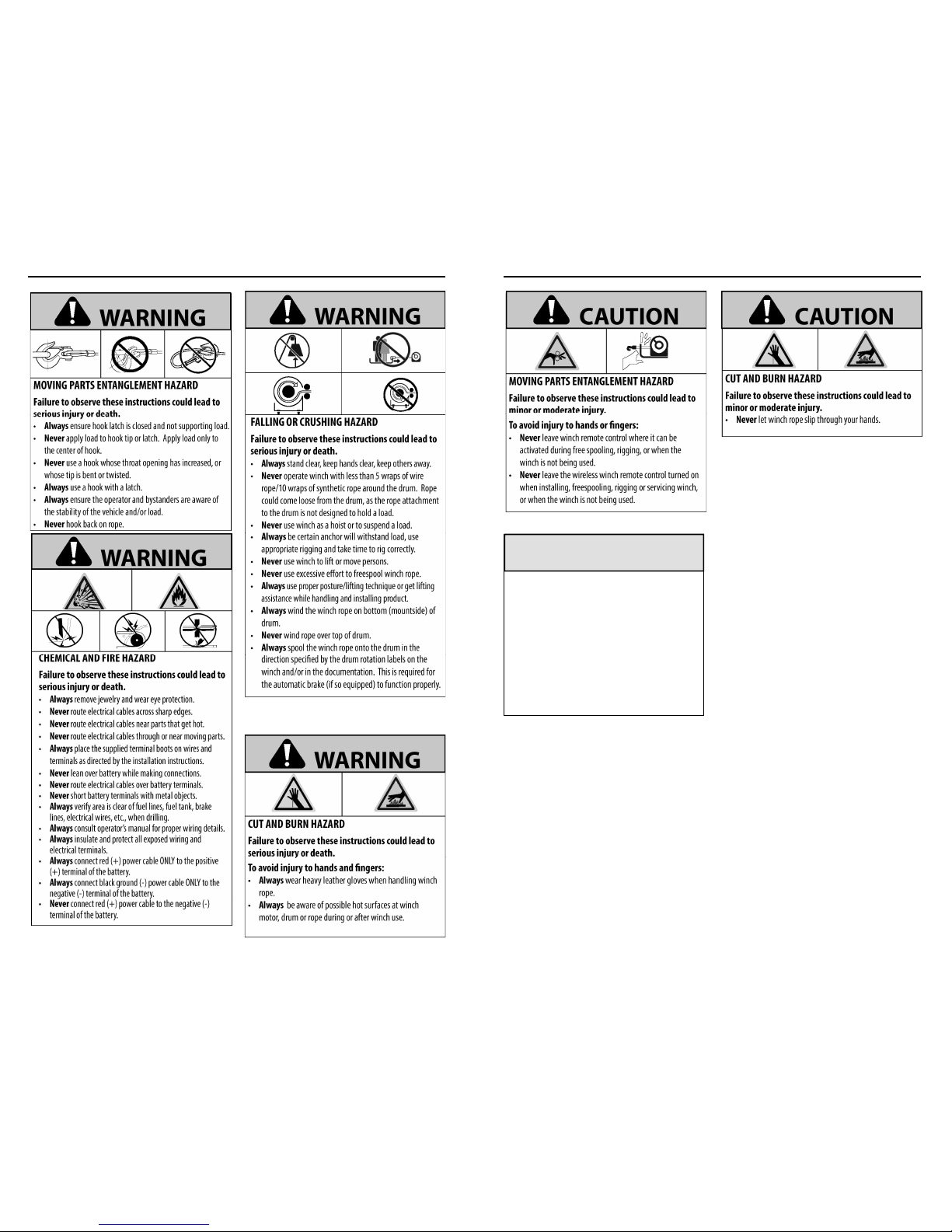
FALLING OR CRUSHING HAZARD
Failure to observe these instructions could lead to
serious injury or death.
•
Always
stand clear, keep hands clear, keep others away.
• Never operate winch with less than 5 wraps of wire
rope/10 wraps of synthetic rope around the drum. Rope
could come loose from the drum, as the rope attachment
to the drum is not designed to hold a load.
• Never use winch as a hoist or to suspend a load.
• Always be certain anchor will withstand load, use
appropriate rigging and take time to rig correctly.
• Never use winch to lift or move persons.
• Never use excessive eff ort to freespool winch rope.
•
Always
use proper posture/lifting technique or get lifting
assistance while handling and installing product.
• Always wind the winch rope on bottom (mountside) of
drum.
• Never wind rope over top of drum.
• Always spool the winch rope onto the drum in the
direction speci ed by the drum rotation labels on the
winch and/or in the documentation. This is required for
the automatic brake (if so equipped) to function properly.
CUT AND BURN HAZARD
Failure to observe these instructions could lead to
serious injury or death.
To avoid injury to hands and ngers:
• Always wear heavy leather gloves when handling winch
rope.
• Always be aware of possible hot surfaces at winch
motor, drum or rope during or after winch use.
WARNING
WARNING
MOVING PARTS ENTANGLEMENT HAZARD
Failure to observe these instructions could lead to
serious injury or death.
•
Always
ensure hook latch is c losed and not supporti ng load.
•
Never
apply load to hook tip or latch. Apply load only to
the center of hook.
•
Never
use a hook whose throat opening has increased, or
whose tip is bent o r twisted.
•
Always
use a hook with a latch.
•
Always
ensure the operator and bystanders are aware of
the stability of t he vehicle and/or load.
•
Never
hook back on rope.
WARNING
CHEMICAL AND FIRE HAZARD
Failure to observe these instructions could lead to
serious injury or death.
•
Always
remove jewelry and we ar eye protection.
•
Never
route electrical cab les across sharp edges.
•
Never
route electrical cab les near parts that get hot.
•
Never
route electrical cab les through or near moving par ts.
•
Always
place the supplied ter minal boots on wires and
terminals as directed by the installation instructio ns.
•
Never
lean over battery w hile making connections.
•
Never
route electrical cabl es over battery terminals.
•
Never
short batter y terminals with metal objec ts.
•
Always
verify area is clear of fu el lines, fuel tank, brake
lines, electrical wires, etc., when drilling.
•
Always
consult operator’s manual for proper wiring details.
•
Always
insulate and protect al l exposed wiring and
electrical terminal s.
•
Always
connect red (+) power cable ONLY to the positive
(+) terminal of the battery.
•
Always
connect black g round (-) power cable ONLY to the
negative (-) terminal of the battery.
•
Never
connect red (+) power cable to the negative (-)
terminal of the batter y.
WARNING
WARN INDUSTRIES
7
GENERAL SAFETY PRECAUTIONS
AVOID WINCH AND EQUIPMENT DAMAGE
• Always avoid side pulls which can pile up winch rope
at one end of the drum. This can damage winch rope or
winch.
• Always ensure the clutch is fully engaged or disengaged.
• Always use care to not damage the vehicle frame when
anchoring to a vehicle during a winching operation.
• Never submerge winch in water, if not IP68 rated.
• Always store the remote control in a protected, clean,
dry area.
NOTICE
MOVING PARTS ENTANGLEMENT HAZARD
Failure to observe these instructions could lead to
minor or moderate injury.
To avoid injury to hands or ngers:
• Never leave winch remote control where it can be
activated during free spooling, rigging, or when the
winch is not being used.
• Never leave the wireless winch remote control turned on
when installing, freespooling, rigging or servicing winch,
or when the winch is not being used.
CUT AND BURN HAZARD
Failure to observe these instructions could lead to
minor or moderate injury.
• Never let winch rope slip through your hands.
CAUTION CAUTION
This manual provides instructions on how to install and operate your WARN® ZEON® Platinum
winch and operating your Advanced Wireless Remote Control.
Always read the Basic Guide To Winching Techniques for complete operational instructions
for your WARN® winch system.
Safety
When installing your WARN® winch system, read and follow all mounting and safety
instructions.
Always use caution when working with electricity and remember to verify that no exposed
electrical connections exist before energizing your winch circuit.
For specifications and performance data, refer to the specification sheet supplied with your winch.
WARN INDUSTRIES
8
GENERAL SAFETY PRECAUTIONS
92821A4
92821A4
Page 7
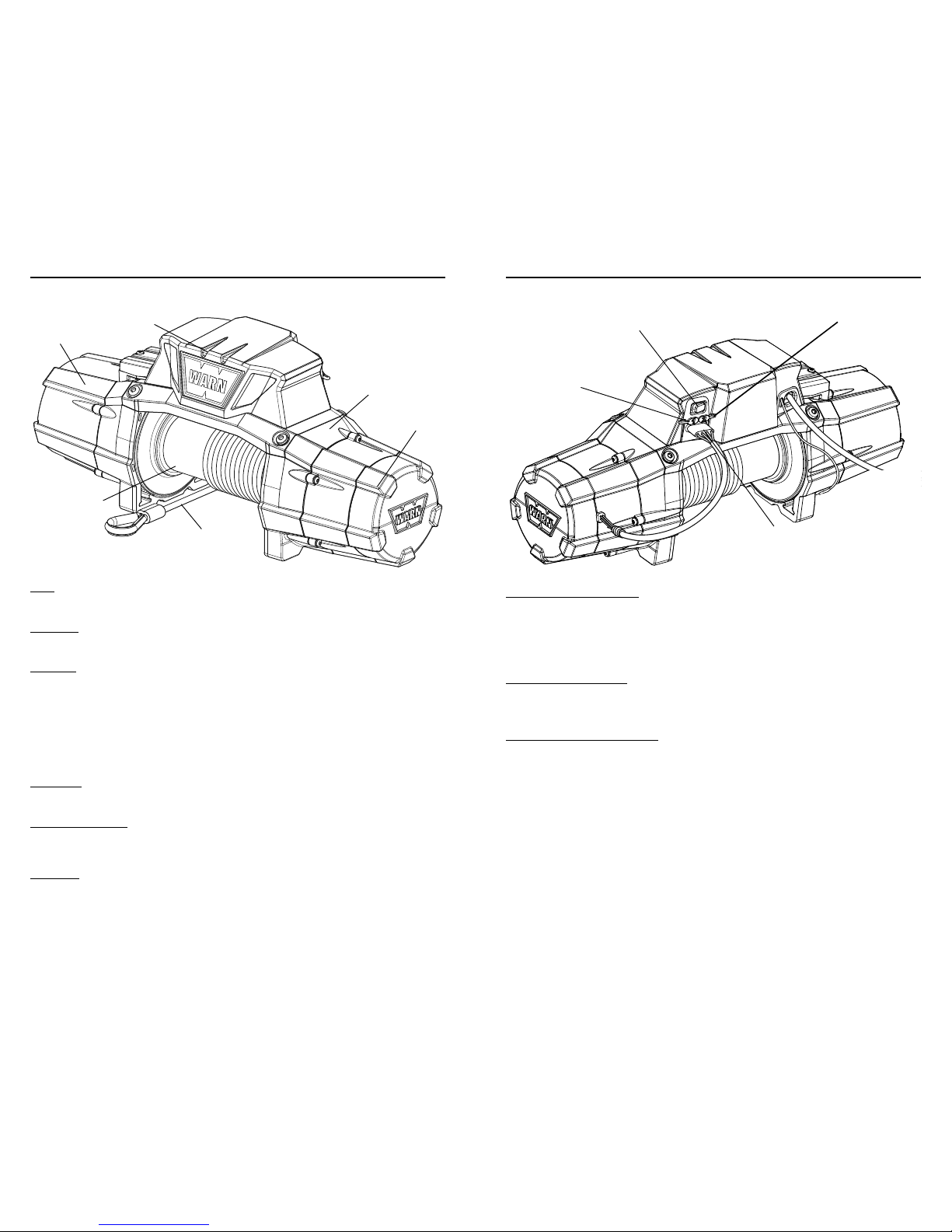
Before you begin, you should familiarize yourself with your WARN® winch and each of its components:
Motor
: The winch motor is powered by the vehi cle’s battery. The motor provides
power to the gear mechanism, which turns the winch drum and winds the
winch rope.
Winch Drum:
The winch drum is the cylinder onto which the winch rope feeds. The
drum is driven by the motor and drive train. Its direction ca n be changed
using the Advanced Wireless Remote Control.
Winch Rope:
The winch rope’s diameter and length are determined by the winch’s load
capacity and design. Wrapped around the winch drum and fed through
the fairlead, the winch rope is looped at the end to accept the hook’s
clevis pin.
For synthetic rope models, be sure to fully read these instructions to
familiarize yourself completely with the Advanced Wireless Remote
Control operation before you attempt to install the optional synthetic
rope. See your WARN® Synthetic Rope Installation Instruction Manual
for detailed synthetic rope installation instructions.
Transmission:
The reduction gear converts the winch motor power in to a large pulling
force. The gear train design makes it pos sible for the winch t o be lighter
and more compact.
Remote controlled clutch :
The remote controlled clutch is concealed within the end cap housing.
It is controlled by the Advanced Wireless Remote Control. It all ows
for engagement and disengagement of the clutch with the Advanced
Wireless Remote Control.
Control Pack:
Using electrical power from the vehicle’s battery, the control pack’s
contactor switches power to the motor, enabling the ope rator to change
the direction of the winch drum rotation.
For specific applications, the optional Control Pack Relocation Kit details
can be found at your WARN® Authorized Dealer or www.warn.
com.
Motor
Control Pack
Transmission
Winch Rope
Winch Dru m
Remote C ontrolled Clut ch
WARN INDUSTRIES
9
KNOW YOUR WINCH
Wireless Control Activation Switch:
The wireless control activation switch activates or deactivates the
wireless control unit.
This switch
must
be ‘ON’ (activated) in order
for the A dvanced Wireless Rem ote Control to operat e the winch.
The wireless control unit uses a very s mall but constant current from
the vehicle battery. It is recommended to turn the switch “OFF”
(deactivate) the unit to prevent draining the vehicle battery when not
operating the vehicle for an extended period of time.
Auxiliary Power Ports (1 a nd 2):
The auxiliary power ports a llow you to connect and control two
separate auxiliary systems from the winch.
The optional Auxiliary Kit details can be found at your WARN®
Authorized Dealer or www.warn.com.
Remote Controlled Clutch Wire H arness
: The remote controlled clutch wire harness plugs into the winch
control pack.
Auxiliar y Power Port 1
Wireless C ontrol
Activatio n Switch
Remote C ontrolled
Clutch Wir e Harness
Auxiliar y Power Port 2
WARN INDUSTRIES
10
KNOW YOUR WINCH
92821A4
92821A4
Page 8
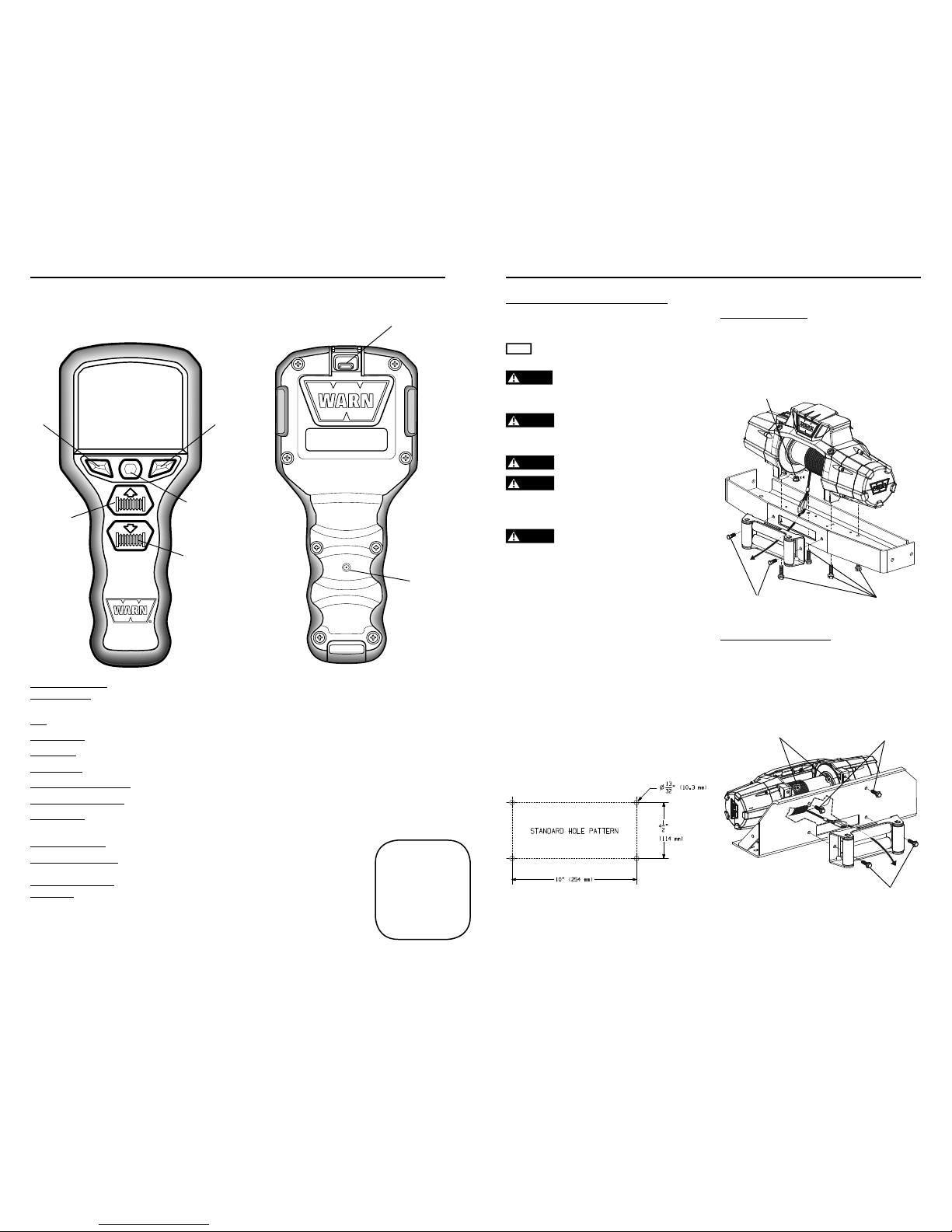
Before you begin, you should familiarize yourself with your WARN® Adva nced Wireless Remote Control
and each of its functions.
Advanced Wireless
Remote Control:
The Advanced Wireless Remote Control allows the operator t o control the winch
and two auxiliaries.
LCD:
Display of fun ction menus, importan t vehicle feedback a nd winch functions.
Select Button:
Press to c onfirm/activate selections .
Left Button:
Press to n avigate left through each menu display.
Right Button:
Press to na vigate right through each menu display.
Winch Power-out Button:
Press to control the power-out operation of the w inch.
Winch Power-in Button:
Press to control the power-in operation of the win ch.
Reset Button
: The reset button is used to restart your remote in rare cases when it functions
incorrectly. Resetting the remote will preserve your settings.
USB Charging Port:
Used to charge the internal b attery.
USB Cable
(not shown)
: Used to c onnect Advanced Wire less Remote Control t o
chargers or your computer to charge.
Car Charger Adapter
(not shown): Car charger allows plugging into car’s DC socket to keep
your Advan ced Wireless Remote C ontrol powered whe n
you are o n the go.
Helpful Hint:
Connect your remote
to a charging device now.
This will allow your remote
to charge while you are
installing your winch. Refer
to page 13 for charging
steps.
USB Charging Port
WARN INDUSTRIES
11
KNOW YOUR ADVANCED WIRELESS REMOTE
LCD
Right
Button
Select
Button
Winch
Power-in
Button
Winch
Power-out
Button
Left
Button
Reset
Button
Mounting Orientation and Hardware
Feet down mounting:
• (4) M10 -1.5 anged hex locknut
• (4) M10-1.5 x 35 hex ange, 8.8, bolt
• (2) 7/16-14 x 1 hex bolt
For feet forward mounting:
• (4) M10x1.5 anged locknut 15mm hex
• (4) M10-1.5 x 35 hex ange, 8.8, bolt
• (2) M10-1.5 x 40 hex ange, 8.8, bolt (found
in separate plastic bag)
Step 1 - Mount the Winch
Winch moun ting kits are available to satisfy nearly
all applicatio ns. For information on available kits,
contact your WARN® product de aler.
NOTICE
For optimal performance and the results you expect,
WARN® mounting plates are strongly recommended.
CAUTION
To prevent accidental activation of the winch
and serious injury, complete the winch installation and attach
the hook before installing the wiring.
WARNING
Always choose a mounting location that is
suffi ciently strong enough to withstand the maximum pulling
capacity of your winch.
WARNING Never use bolts that are too long.
WARNING Always spool the winch rope onto the drum
in the direction speci ed by the drum rotation labels on the
winch and/or in the documentation. This is required for the
automatic brake (if so equipped) to function properly.
WARNING Always wind the winch rope on the bottom
(mount side) of the drum.
This winch should always be m ounted in a
horizontal or ientation with the ro pe winding on
and off t he drum on the mount side (bottom) of the
drum.
Correct rota tion is required for the automatic
brake to function properly. Ho rizontal mounting
helps preven t the rope from p iling up on one e nd of
the drum which can damage the winch.
Always u se recommended bolt and washer
combinations torqued to recomme nded levels.
Specifications listed below. Mou nting system will
dictate bolt length.
Mounting Bolt Pattern:
Standard: 10”x 4.5” (54 mm x 114.3 mm)
Smooth and at mounting surface, minimum
thickness = 1/4” (6.4 mm)
(2) M10-1.5 x 35
(2) M10-1.5 x 40
(found in separate bag)
(4) M10-1.5 anged hex
locknut
(4) M10-1.5 anged hex
locknut
(4) M10-1.5 x 35
anged hex bolt
(2) 7/16-14 x 1 hex
bolt
WARN INDUSTRIES
12
MOUNTING
92821A4
92821A4
Page 9
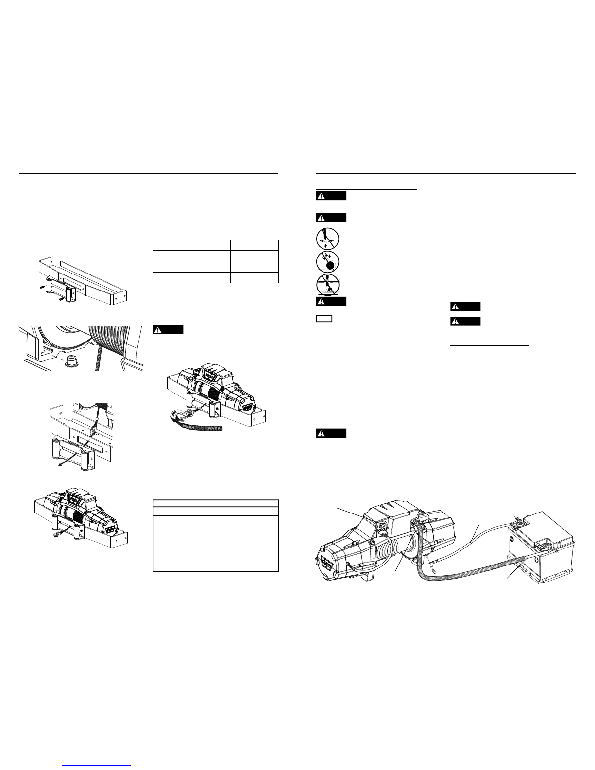
Mount Winch:
1. Choose a m ounting location that is sufficiently
strong enoug h to withstand the maximum
pulling cap acity of your winch.
2. Install your mounting bracket per your specific
mounting kit instructions.
3. Fasten fairlead to mounting bracke t using
the (2) b olts specified above f or your specific
mounting o rientation. See the
Mounting
Orientation
section f or hardware specifics
.
4. Set the (4) flanged nuts into pockets of winch
feet.
5. Thread the hook loop end of the rope through
the opening of mounting bracket and fairlead.
NOTE: Do not re move plastic wrap from
remaining rope on drum at this time.
6. Set w inch in mount.
7. See table b elow to confirm requ ired bolt length.
Plate Thickness Bolt Length
7 mm (1/4”) 32 mm
10 mm (3/8”) 40 mm
13 mm (1/2”) 40 mm
8. Review moun ting orientation on p age 10 for
bolt sizing.
9. Install bolts and tighten to 41 to 47 Nm (30-35
ft. lbs.).
WARNING
Always con rm required bolt length to
ensure proper thread engagement.
10. Attach hook to winch rope loo p.
11. Attach hook s trap to hook.
12. Remove plastic wrap from remaining rope on
drum.
13. Mounting your winch is now comp lete. Check
all hardware to be sure it is tight and to torq ue.
You can now move on to Install the Wiring.
NOTE
OPTIONAL SYNTHETIC ROPE INSTALLAT ION
For synthetic rope models, be sure to fully read these
instructions to familiarize yourself completely with
the Advanced Wireless Remote Control operation
before you attempt to install the optional synthetic
rope. See your WARN® Synthetic Rope Installation
Instruction Manual for detailed synthetic rope
installation instructions.
WARN INDUSTRIES
13
MOUNTING
Step 2 - Install the Wiring
WARNING
To prevent serious injury or death. Always
place the supplied terminal boots on wires and terminals as
directed by the installation instructions.
WARNING
To prevent serious injury or death from
electrical re:
Never route electrical cables across sharp edges.
Never route electrical cables near parts that get
hot.
Never route electrical cables through or near
moving parts.
Avoid pinch and wear/abrasion points when
installing all electrical cables.
WARNING
Always insulate and protect all exposed wiring
and electrical terminals.
NOTICE
A fully charged battery and good connections are
essential to the proper operation of your winch. The minimum
requirement for a 12 volt DC battery is 650 Cold Cranking Amps.
Route battery connection cables in areas which
will not cause them to chafe or cut through the
insulation ca using a potential sh ort circuit.
The winch power wire must b e routed to the
battery. A direct battery con nection of the power
(red) and ground (black) cable is required.
Do not
connect ground to vehicle chassis.
Routing the battery connection cables may
require remo val of vehicle facia or body parts.
Always rou te battery cables alon g a path that
allows the cables to be secur ed with zip ties.
WARNING
Loose or unsecured power cables can cause
serious injury or death.
Always prot ect power cables fro m sharp edges,
areas that get too hot to to uch with your hand and
any moving parts.
1. Plan the routing path.
2. Loosely secure power cables along path.
3. Confirm power cables are protected f rom sharp
edges, heat and moving parts. Consider chassis
flex and vibration which might damage cable.
4. Carefully inspect electrical cable routing. Zip tie
and secure electrical cables. Zip ties sh ould be
snug, but not cutting into wire insulation. Use
electrical tape, pieces of rubber hose or electrical
conduit to protect electrical cables and wire
harness where needed to avoid electrical cable
insulation wear or abrasion.
5. FIRS T, attach the winch power (red) cable to the
positive (+) battery terminal. SEC OND, attach the
ground (black) cable to the negative (-) battery
terminal.
WARNING
Always connect red (+) power cable ONLY to the
positive (+) terminal of the battery.
WARNING
Always connect black ground (-) power c able ONLY
to the negative (-) terminal of the battery.
Step 3 - System Check
Perform sy stem check:
1. Check fasteners and make sure they are tight and
to proper torque
2. Verify the wireless control activation switch light
turns ON. A flashing green light appears in the
switch. If light does not turn on, immediately
check to ensure power cables are correctly
connected to the battery, red to (+) an d black to (-).
If not, disconnect and reconnect as instructed.
3. Verify all electrical wiring to all components is
correct and be certain that all connections are
tight.
4. Verify there is no exposed/bare wiring, terminals or
cable insulation damage.
5. Read The Basic Guide to Winching Techniques
completely before operating your winch.
6. Charge remote.
Once you have performed a system check, you ar e
ready to perform “First Time Operating Instructions”.
Ground ( black) Cable
Power (red) Cable
Wireless C ontrol
Activation Switch
Control Pack Ground
Wire
WARN INDUSTRIES
14
ELECTRICAL CONNECTIONS
92821A4
92821A4
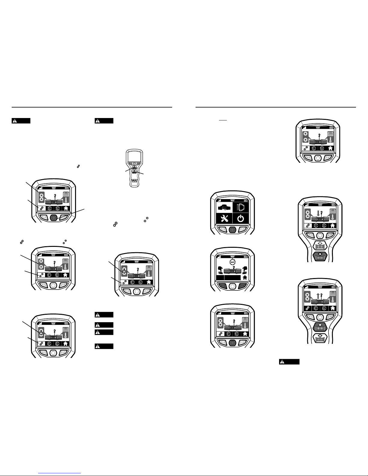
Page 10
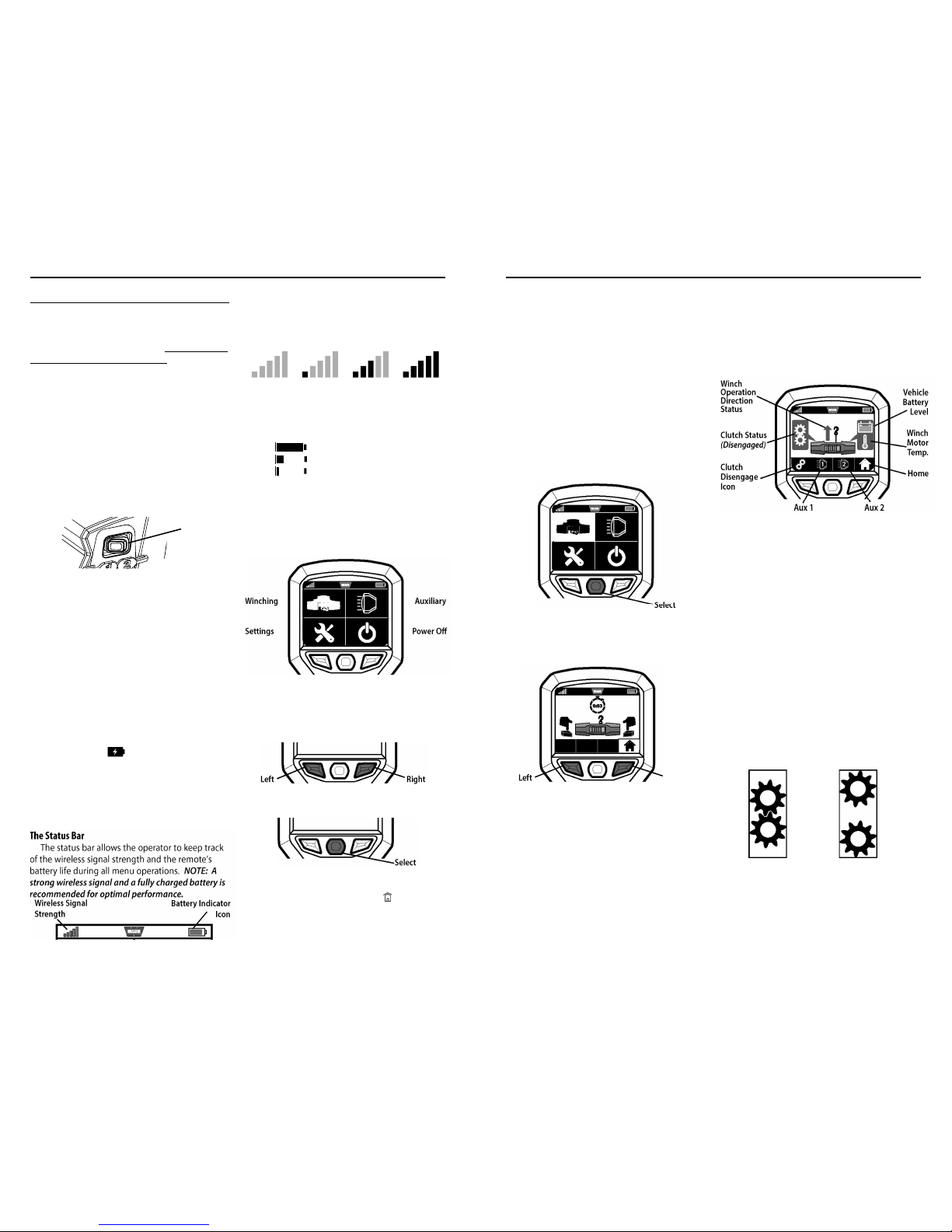
Wireless Signal
Strength
Battery Indicator
Icon
Winching Auxiliary
Settings Power Off
Left Right
Select
Fully charged battery (green)
Low charged battery (yellow)
Critically low battery (red)
No Signal Weak Signal Fair Signal Strong Signal
X
WARN INDUSTRIES
15
FIRST TIME OPERATING INSTRUCTIONS
The bars on the wireless signal strength icon will
light up in sequence to show signal strength.
The remote control’s battery indic ator icon
indicates the state of the inter nal battery by
changing co lor and fill level of battery icon.
NOTE: If you r battery icon shows at a critically low level,
you must charge the battery or plug into p ower source.
Home Menu
Turn on the remote by pressi ng any button. Th is
will automa tically bring up the Home Menu.
From the Home Menu, you ca n access each of
the four o perations.
Four Operations:
1) Winching 2) Auxiliary
3) System Settings 4) Power Off
1. Use the lef t and right buttons on your remote
to navigate through the operati on menus.
2.
To activate an operation, press select.
NOTE: To return to the Home Menu from othe r
menus, navigate to the Home Icon (
) in the menu
bar and press Select.
In this section, we’ll show you the first time operating
instructions for effective basic winch ing. For complete
winch operation and techniques read the Basi c Guide to
Winching Techniqu es found online at http://ww w.warn.
com/corporate/literaturer equest.shtml.
Getting Started
Your ZEON ® P latinum Winch is op erated by the
new Advance d Wireless Remote Control.
The Advance d Wireless Remote Control is
designed to allow the operator to control the win ch
and two a uxiliaries remotely.
1. Verify the wireless control switch (located on
back of c ontrol pack) is “ON” (a green flashing
light appea rs inside switch). T he switch
must
be ‘ON’ ( activated) in order for the Advanced
Wireless Rem ote Control to oper ate the winch.
Charging the Battery
Your WARN® Advanced Wireless R emote Control
is powered by an internal rech argeable lithium ion
battery. A lthough the battery will arrive partially
charged, you must fully charge the battery or plug
into a po wer source before u se.
1. Connect the included USB charger to the
Advanced W ireless Remote Contro l.
2. Plug other e nd of the USB ch arger into a power
source (such as the included auto charger, a
wall charger or a computer U SB port).
NOTE:
Remote is operable while charging.
3. The remote control will power o n and the
charging ico n (
) will appear inside the
battery indi cator in the upper right corner of
the menu, indicating the remote is charging.
4. The remote is fully charged wh en the battery
indicator ico n is filled.
NOTE: Allow a minimum
of two hours for battery to fully charge.
The Status Bar
The status bar allows the op erator to keep track
of the wi reless signal strength and the remote’s
battery life during all menu o perations.
NOTE: A
strong wireless signal and a fully charged battery is
recommended for opt imal performance.
Step 4 - First Time Operating Instructions
Wireless C ontrol
Activation
Switch
Select
Left
Right
Winch
Operation
Direction
Status
Vehicle
Battery
Level
Home
Winch
Motor
Temp.
Aux 1 Aux 2
Clutch
Disengage
Icon
Clutch Status
(Disengaged)
WARN INDUSTRIES
16
FIRST TIME OPERATING INSTRUCTIONS
Winch Menu
Your winch is completely contr olled by the
WARN® Adv anced Wireless Remote Control.
You should practice activating th e Winch Menu
a few tim es to get familiar with its functions be fore
you move on to the “Winchin g” section of this
manual.
Activate Winch Operation Menu
1. Read The B asic Guide to Winc hing Techniques
thoroughly b efore you attempt to operate your
winch.
2. From the H ome Menu, navigate to the Winch
Icon using the Left and Right buttons and press
Select.
3. Following th e Win ch Activation Menu p rompt,
press and hold the Left and Right buttons
simultaneousl y for 3 seconds to activate the
Winch Opera tion menu.
Note: The Win ch Activation Menu will revert back to
the Home Menu if at idle for one minute.
The main purpose of the Winc h Operation
Menu is to operate your winc h. However, you are
also able t o control your aux iliary systems, keep
track of yo ur vehicle battery level, w inch motor
temperature, winch operation dire ction, clutch
status, wirel ess signal strength a nd the remote
battery life .
NOTE: The Winch Operation Menu is accessible
from any menu by pressing and holding the left and
right buttons simultane ously for three seconds.
Remote Controlled Clutch Basics
The WARN® ZEON® Platinum winc h is equipped
with a re mote controlled clutch . It allows for
engagement and disengagement of the clutch with
the Advanc ed Wireless Remote C ontrol.
When the clutch is engaged, power is transferred
from the w inch motor to the drum and winch rope,
resulting in the power-in or p ower-out operation.
NOTE: Your WAR N® ZEON® Platinum winch clutch
will always default to the engaged position.
When the clutch is disengaged the drum is in
the freespoo l position, allowing the drum to rotate
freely. Fr eespooling is generally the quickest and
easiest way to spool out winc h rope.
Disengaged Clutch
(Freespool)
Engaged Clutch
(Winching)
92821A4
92821A4
Page 11
Clutch Status
(ERROR)
Clutch
Disengage
Icon
Winch
Power-out
Winch
Power-in
Clutch Status
(ERROR)
Clutch
Disengage
Icon
Clutch
Disengage
Icon
Clutch Status
(Disengaged)
WARN INDUSTRIES
17
FIRST TIME OPERATING INSTRUCTIONS
Disengage Remote Controlled Clutch
WARNING
Never engage or disengage clutch if winch is
under load, winch rope is in tension or drum is moving.
1. Make sure t he winch rope is n ot under tension.
NOTE: The clutch will not disengage if the winch
rope is under ten sion. If tension exists, powerout enough rope t o remove any tension from
the winch rope.
2. Activate the Winch Operation Men u (
refer to
page 14
).
3. Navigate to the clutch disengage icon (
) in
the menu bar on the winch function menu and
press Select.
4. Once the c lutch is successfully d isengaged,
the gears in both the clutch status and clutch
disengage ic on will change from “engaged”
(
) status to “disengaged” ( ) st atus.
If clutch d oes not disengage when requested, a
warning er ror will display within the clutch status
icon. Se e Trouble Shooting s ection in this manua l
for possible solutions.
Engage Remote Controll ed Clutch
WARNING
Never engage or disengage clutch if winch is
under load, winch rope is in tension or drum is moving.
After you have disengaged the clutch, there are
three ways the clutch can be engaged.
• Push the Win ch Power-in
or
Winch Power-out
button.
• Return to the Home Menu and th e clutch will
immediately r eturn to engage s tatus.
• After five minu tes the clutch will automatically
engage.
Once clutch is successfully eng aged, the
clutch statu s icon and the clu tch disengage icon
will change from “disengaged” (
) status to
“engaged” (
) status.
If clutch d oes not engage whe n requested, a
warning er ror will display within the clutch status
icon. Se e Trouble Shooting s ection in this manua l
for possibl e solu tions.
WINCHING
WARNING
Always wear heavy leather gloves when
handling winch rope.
WARNING
Never exceed winch’s rated line pull.
WARNING
Always prestretch rope and respool under load
before use. Tightly wound rope reduces chances of “binding”,
which can damage the rope.
WARNING
Never operate winch with less than 5 wraps of
wire rope/10 wraps of synthetic rope around the drum. Rope
could come loose from the drum, as the rope attachment to the
drum is not designed to hold a load.
Select
Clutch
Disengage
Icon
Clutch Status
(Engaged)
5. Confirm clutch (disengage /freespoo l) status.
6. Freespo ol winch rope to anchor point and secure.
Pulling
1. Thoroug hly read The Basic Guide to Winching
Techniques for complete Pulling Instructions.
2. Power-in to start winching.
3. Secure vehicle .
4. Power-out to release tension in winch rope.
5. Disconnect win ch rope from anch or.
6. Power-in win ch rope for storage.
WARNING
Never spool in rope hook against the fairlead.
Next, are c ondensed procedures for winching
operation. You
must
read the Basic Guide to
Winching Tec hniques manual for complete
procedure in structions.
Stretching Winch Rope
Tensioning t he winch rope is c ritical to ensure
a long pr oduct life. Tensioning the winch rope w ill
prevent oute r layers of winch rope from pinching
and deformin g the inner layers.
1. Read your B asic Guide to Winch ing Techniques
for Stretchi ng Winch Rope instru ctions.
Rigging
1. Thoroug hly read The Basic Guide to Winching
Techniques for complete Rigging Instructions.
2. Select Winchin g function.
3. Activate winc h.
4. Disengage Cl utch.
NOTE: The clutch will not disengage if the winch
rope is under ten sion.
WARN INDUSTRIES
18
FIRST TIME OPERATING INSTRUCTIONS
92821A4
92821A4
Page 12
Select
WARN INDUSTRIES
19
FIRST TIME OPERATING INSTRUCTIONS
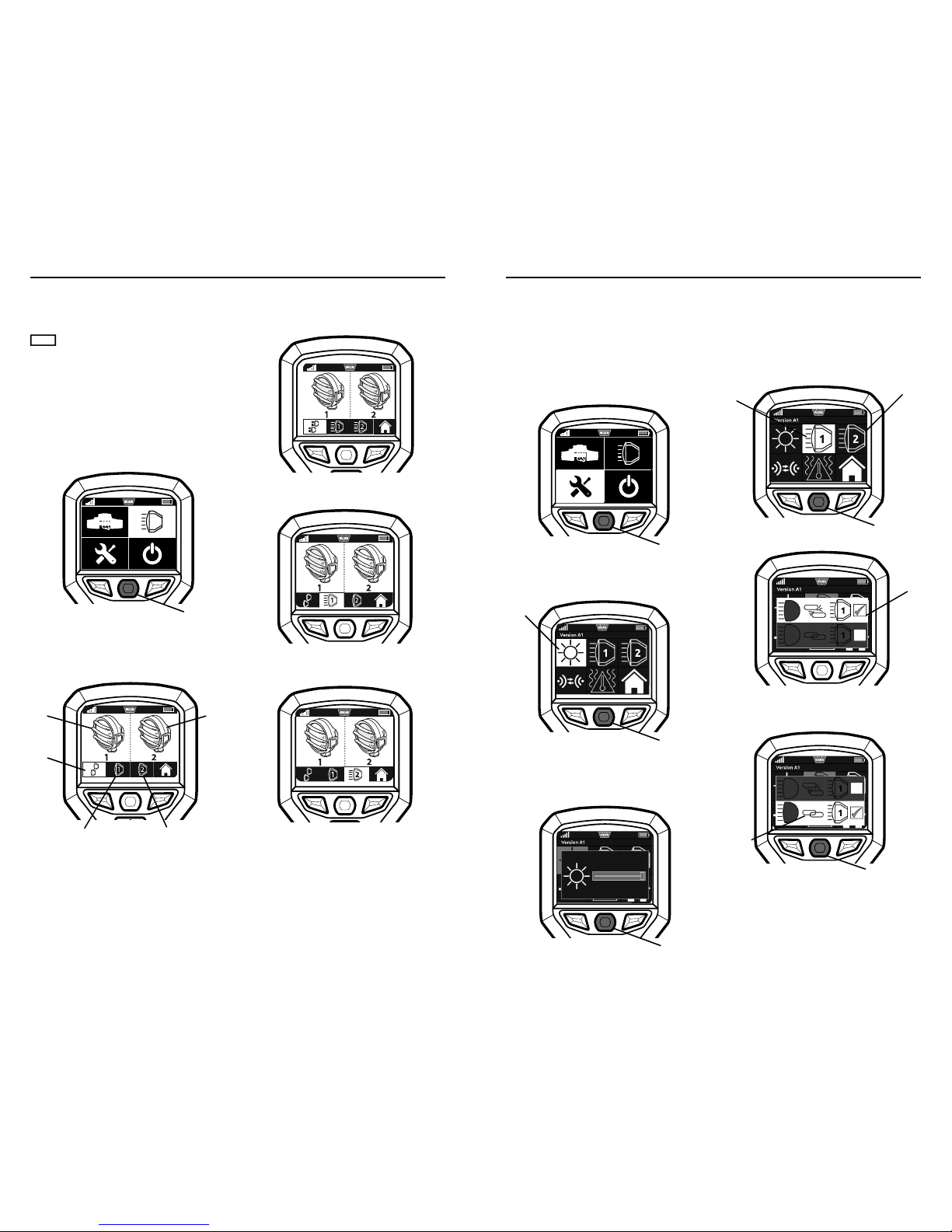
Auxiliary Menu
Your WARN® Advanced Wireless R emote Control
can control up to two separate auxiliary systems*.
NOTICE
*
Auxiliary systems must be rated for 12 v and
draw less than 16 amps.
Auxiliary co nnection adapter kits are necessary
in order t o operate the auxiliar y system. For
information on available kits, con tact your WARN®
product dea ler, WARN Customer Service or www.
warn.com.
Activate Auxiliary Operation Menu
1. From the Home Menu, navigate to the Auxiliary
Icon and p ress Select.
Auxiliaries c an be switched on and off together
using the Dual Auxiliary Icon or individually by
using the Auxiliary 1 and Aux iliary 2 Icon and then
pressing Sel ect.
When an auxiliary is OFF the icons will show
outlined. Wh en an auxiliary is ON, the icons will
appear solid .
Dual Auxiliary ON
Auxiliary 1 ON
Auxiliary 2 ON
Aux 1
Status
Aux 2
Status
Dual
Aux
Icon
Aux 1
Icon
Aux 2
Icon
Select
Brightness
Icon
Select
Auxiliar y 1
Unlinked
Select
Auxiliary 1
Auxiliary 2
Select
Auxiliar y 1
Linked
WARN INDUSTRIES
20
FIRST TIME OPERATING INSTRUCTIONS
Link Auxiliary High Beam
With your Advanced Wireless Re mote, you are
able to link you r auxiliaries to your vehicle high
beam settin g.
1. To link the auxiliary (1 or 2) with your vehicle’s
high beam setting, navigate to the Auxiliary 1 or
2 Icon and press Select.
2. The auxiliarie s default as unlinked.
3. Using your left or right button to highlight the
“linked” ico n. A check mark will appear in the
box. Pre ss select to confirm selection.
Note: Images show linking Auxiliary 1. Same pr ocess
will be used for Auxiliary 2 linking.
Settings Menu
From your Setting menu, you are able to adjust
screen brig htness, pair your rem ote, link auxiliaries
to your h igh beam setting and turn on the ther mal
shut-off opt ion.
Activate the Settings Operation Menu
1. From the Home Menu, navigate to the Settings
Icon and p ress Select.
Adjust Brightness
1. To adjust t he brightness, navigate to the
Brightness Ic on and press Select .
2. Use the Lef t and Right buttons to adjust slider
to the de sired brightness. On ce the brightness
is at the desired level, press Select to close the
brightness ad just panel.
Select
92821A4
92821A4
Page 13

Wireless
Control
Activation
Switch
Select
Pairing
Icon
WARN INDUSTRIES
21
FIRST TIME OPERATING INSTRUCTIONS
Pairing the Remote Control
WARNING
Never pair more than one winch and one
remote at a time.
Your Advanc ed Wireless Remote Control will
arrive alread y paired to your W ARN® ZEON®
Platinum wi nch system, however, replacement
remotes wil l need to be paire d.
1. To pair the remote to a winch , navigate to the
Pairing Icon and press Select.
2. Press and hold select and the right button
simultaneousl y for 3 seconds to bring up the
pairing con firmation menu.
3. To continue pairing, select the green check
mark icon by navigating with t he left or right
buttons and press Select.
4. After selecti ng the green check mark icon,
a timer w ill begin counting do wn from 30
seconds.
5. During this time, turn the Wirel ess Control
Activation S witch on the back of the control
pack to O FF and then ON a gain.
6. If pairing is successful, a green check mark will
appear.
7. If pairing w as unsuccessful, the red X mark will
remain, and the remote will r emain unpaired.
Select
Right
Button
Select
Thermal
protectio n
deactivated
Select
Thermal
protection
Icon
Thermal
protectio n
activated
WARN INDUSTRIES
22
FIRST TIME OPERATING INSTRUCTIONS
8. If pairing w as unsuccessful, repeat steps 1-5.
9. To close the pairing panel, pre ss Select.
Thermal Protection Setting
Your Advanc ed Wireless Remote has a thermal
protection s etting, giving you the option to have
the winch shut off automatically when it reaches a
high tempe rature protection point .
1. To activate the thermal protection setting,
navigate to the thermal Icon a nd press Select.
2. The thermal protection system de faults as
deactivated.
3. To activate the thermal protection setting, use
the left or righ t button to highlight the thermal
protection s hut-off option. A check mark will
appear in the box. Press select to confirm
selection.
92821A4
92821A4
Page 14

WARN INDUSTRIES
23
TROUBLESHOOTING
Trouble Shooting/Error Conditions
Problem Error Message Possible cause Corrective action
Winch is not
operating
Low wireless strength
Make sure your Advanced
Wireless Remote Control is
within range.
Wireless Remote
Control Activation
Switch is in the OFF
position
Turn ON the Wireless Remote
Control Activation Switch
Winch control pack is
under water. Wireless
signal will not transmit
under water.
Winch control pack needs
to be above water to receive
wireless signal. See www.
warn.com for accessories.
Remote controlled
clutch does not
disengage when
requested
Tension or Load
exists on the winch,
preventing the clutch
from disengaging.
Power-out winch until winch
rope is no longer under load.
The remote controlled
clutch is disconnected
from the control pack.
Check the 4-pin remote
controlled clutch connector
on the back of the control
pack to be sure it is rmly
connected.
The remote controlled
clutch is damaged.
Contact WARN® customer
service for further information.
Remote will not
operate
The remote battery is
critically low.
Charge the remote battery
See charging instructions on
page 13.
Auxiliary will not
turn on
Auxiliary is not
connected
Check auxiliary connector and
cables.
Auxiliary short
circuit
Accessories wiring
faulty; Accessory
electrical load is
to high.
*
Auxiliary
systems must be rated
for 12v and draw less
than 16 amps.
Check wiring; reduce electrical
load.
Wireless signal
strength is low
Decrease distance between
remote control and winch.
Check
Before rst
operation
After each
use
Every 90 days
Take time to fully read the Instructions and/
or Operations Guide, and/or Basic Guide to
Winching Techniques, in order to understand
your winch and its operations
X
Check fasteners and make sure they are tight
and to proper torque.
Replace damaged fasteners.
X X
Verify wiring to all components is correct and
be certain that all connections are tight.
X X
Verify there is no exposed/bare wiring,
terminals or cable insulation damage
(cha ng/cutting).
Cover any exposures with terminal boots.
Repair or replace damaged electrical cable.
X X
Inspect rope for damage.
Replace rope immediately if damaged.
X X X
Keep winch, rope and switch control free
from contaminants.
Use a clean rag or towel to remove any dirt
and debris.
X
Charge Remote
X X
Take time to fully understand your winch and the
winching operation by reviewing the Basic Guide
to Winching Techniques found online at:
http://www.warn.com/corporate/literaturerequest.shtml.
For further information or any questions
contact:
WARN INDUSTRIES, INC.
12900 S.E. Capps Road, Clackamas
OR USA 97015-8903, 1-503-722-1200,
Customer Service: 1-800-543-9276
Dealer Locator Service: 1-800-910-1122
or visit www.warn.com.
Disposal
Batteries should not be disposed of in genera l
household was te. Obser ve the local waste disposal
regulations, detai ls of which can be obtained fro m
your local auth ority.
All electrical and electronic equipment must
be disposed of separately from general
household waste using the sites designated
by local authorities.
If a product displays this symbol of a
crossed-out wheelie bin, the product is
subject to European Directive 2012/19/EC.
The appropriate dis posal and separate collection of
used equipme nt serve to prevent potential har m to
the environment an d health. They are a prerequisite
for the re-use and recycling of used electr ical and
electronic equi pment.
For further inform ation on disposing of your use d
equipment, plea se contact your local authorit y or
your refuse collec tion service.
WARN INDUSTRIES
24
FINAL ANALYSIS AND MAINTENANCE
92821A4
92821A4
Page 15

Chaque situation de treuillage peut potentiellement occasionner des blessures. Afin
de minimiser ce risque, il est important de lire attentivement TOUTES les instructions
et informations de sécurité afférentes à votre produit. Veillez à vous familiariser avec le
maniement du treuil avant de l'utiliser et à vous préoccuper avant tout de la sécurité. Ces
instructions fournissent des informations et des consignes de sécurité importantes concernant
l’installation et l’utilisation du treuil.
Vous trouverez dans ce kit la documentation suivante:
• Guide d’installation du treuil / Instructions relatives à une première utilisation
• Garantie du produit
CONSERVEZ CE MANUEL et tous les autres documents relatifs au produit à titre de référence
et consultez-les fréquemment pour assurer un fonctionnement continu en toute sécurité.
Demandez à tous les utilisateurs de ce produit de lire le présent manuel avant de l'utiliser.
Autres documents relatifs au produit disponibles en ligne
:
• Manuel de base des techniques de treuillage
• Fournit une compréhension globale du treuil et vous enseigne les techniques de
treuillage. Il s’agit d’une ressource utile qui favorise l’utilisation efficace et sûre du
treuil.
• Caractéristiques du produit et données de performance
• Fournit les caractéristiques du produit, les données de performance et les
renseignements concernant les pièces de rechange.
• Autres documents relatifs à des produits spécifiques
Consultez le site
www.warn.com/corporate/literaturerequest.shtml
pour accéder à d’autres
documents ou à des documents sur les produits de remplacement, disponibles en consultation/
téléchargement.
WARN INDUSTRIES
25
Warn Industries Inc.
12900 SE Capps Road
Clackamas, OR 97015
États-Unis
Service à la clientèle : (800) 543-9276
No. de télécopie international : (503) 722-3005
Télécopie: (503) 722-3000
www.warn.com
Warn® et le logo WARN sont des marques déposées de Warn Industries Inc.
©2014 Warn Industries Inc.
Manuel d'utilisation et d'installation
du treuil ZEON® Platinum et de la
télécommande sans fil évoluée
TABLE DES MATIÈRES :
SÉCURITÉ
Index des symboles .................................... .................................................................................................................... 27-28
Mesures générales de sécurité et Industrie Canada ................................................ ...........................................29-32
INSTRUCTIONS
Se familiariser avec le treuil ..................................................... .................................................................................... 33-34
Se familiariser avec la télécommande sans fil évoluée ......................................................... .................................. 35
Montage ................................................................... ........................................................................................................... 36-37
Raccordements électriques ................................ ............................................................................................................... 38
Vérifications du système .............................. ....................................................................................................................... 38
Instructions relatives à une première utilisation ........................................................................... ......................39-46
Premiers contacts................................. ...................................................................................................................... 39
Utilisation du menu principal .................................. .............................................................................................. 39
Utilisation du menu du treuil .......................................................................................................................... 40-42
Utilisation du menu des systèmes auxiliaires ........................................................................... .......................43
Utilisation du menu des paramètres ............................................................................................................ 44-46
Dépannage/conditions d'erre ur ............................................. ......................................................................................... 47
Dernière analyse et entretien ............................................................................................................................. .............48
WARN INDUSTRIES
26
INSTRU CTIONS
92821A4
92821A4
Page 16

SYMBOLE EXPLICATION
Lire tous les documents
relatifs au produit
Certains littérature disponible
uniquement onlinewww.warn.com/
corporate/literaturerequest.shtml.
Toujours porter un
dispositif de protection
auditive et oculaire
Ne jamais utiliser le treuil
comme palan
Positionner correctement
la charge dans la gorge
du crochet
Enrouler le câble sur le
dessous du tambour
Danger d’écrasement
des doigts dans le guide-
câble
Risque de percement/
coupure des mains
Risque d’explosion/
rupture
Ne jamais faire passer
les câbles électriques
par-dessus des bords
tranchants.
Éviter les points de
pincement et d’usure/
abrasion lors de
l’installation des câbles
électriques
SYMBOLE EXPLICATION
Toujours porter des
gants de cuir
Ne pas déplacer des
personnes
Toujours utiliser la sangle
de crochet fournie
Ne jamais appliquer la
charge sur l’extrémité ou
le loquet du crochet
Ne jamais enrouler le
câble sur le dessus du
tambour
Point de pincement du
guide-câble
Risque de surface
chaude
Risque d’incendie et de
brûlure
Ne jamais faire passer
les câbles électriques
à travers des pièces
mobiles ou à proximité.
Danger de ls nus,
isoler les ls nus et les
terminaux
Ne jamais accrocher le
câble à lui-même
WARN INDUSTRIES
27
INDEX DES SYMBOLES
Index des symboles pour le treuil
WARN INDUSTRIES
28
INDEX DES SYMBOLES
Index des symboles pour la télécommande sans l
SYMBOLE EXPLICATION
Appairage
Alimentation
Protection thermique
Charge de la batterie de
la télécommande sans l
Paramètres
Câble de batterie du
véhicule
De treuil
Température du moteur
de treuil
Enroulement
Déroulement
Force du signal de la
télécommande
SYMBOLE EXPLICATION
Auxiliaire (Aux)
1
Auxiliaire 1 (Aux 1)
2
Auxiliaire 2 (Aux 2)
Luminosité
Débrayé
Embrayé
Erreur de fonctionnement
du débrayage
Auxiliaire double (Aux
double)
Menu principal
Lien avec les phares non
établi
Lien avec les phares
établi
92821A4
92821A4
Page 17

Les directives suivantes comprennent
des indications intitulées AVERTISSEMENTS, AT TENTION,
AVIS et REMARQUES. Chacune d’entre elles comporte un
objectif bien précis: AVERTISSEMENT présente des consignes
de sécurité soulignant un danger potentiel qui, s’il n’est
pas évité, peut entraîner des blessures graves ou la mort.
ATTENTION comprend des consignes de sécurité signalant
un danger potentiel qui, s’il n’est pas évité, peut entraîner
des blessures légères ou modérées. ATTENTION sert aussi
à signaler une utilisation dangereuse. ATTENTION et
AVERTISSEMENT identi ent un danger, indiquent comment
l’éviter et montrent ses conséquences possibles si on l’ignore.
AVIS présente des consignes visant à éviter les dommages
matériels. REMARQUE donne des renseignements
additionnels qui aident à accomplir une procédure.
TRAVAILLEZ PRUDEMMENT!
Avertissements et mises en garde
Industrie Canada
Le présent appareil est conforme aux CNR d’Industrie Canada
applicables aux appareils radio exempts de licence. L’exploitation
est autorisée aux deux conditions suivantes:
(1) l’appareil ne doit pas produire de brouillage, et
(2) l’utilisateur de l’appareil doit accepter tout brouillage
radioélectrique subi, même si le brouillage est
susceptible d’en compromettre le fonctionnement.
Conformément à la réglementation d’Industrie Canada, le
présent émetteur radio peut fonctionner avec une antenne
d’un type et d’un gain maximal (ou inférieur) approuvé pour
l’émetteur par Industrie Canada. Dans le but de réduire les
risques de brouillage radioélectrique à l’intention des autres
utilisateurs, il faut choisir le type d’antenne et son gain de
sorte que la puissance isotrope rayonnée équivalente (p.i.r.e.)
ne dépasse pas l’intensité nécessaire à l’établissement d’une
communication satisfaisante.
L’émetteur radio (identi er l’appareil par son numéro de
certi cation ou par son numéro de modèle si la catégorie est II)
a été approuvé par Industrie Canada pour fonctionner avec les
types d’antennes gurant dans la liste ci-dessous et l’impédance
d’antenne maximum requise est indiquée pour chaque type
d’antenne. Il est strictement défendu d’utiliser avec cet appareil
des types d’antennes qui ne sont pas incluses dans cette liste
et qui ont un gain supérieur au gain maximum indiqué pour ce
type d’antenne.
DANGER DE HAPPEMENT PAR DES PIÈCES MOBILES
Le non-respect des consignes peut entraîner des
blessures graves ou la mort.
Consignes de sécurité générales:
• Il faut toujours avoir une bonne connaissance du treuil. Prendre
le temps de bien lire le manuel d’utilisation, et/ou le manuel
de base des techniques de treuillage, a n de comprendre le
treuil et son fonctionnement, trouvés en ligne à
http://www.
warn.com/corporate/literaturerequest.shtml.
•
Ne jamais
excéder la capacité nominale du treuil ou du câble
de treuil. Un câblage double avec poulie ouvrante permet de
réduire la charge subie par le treuil.
•
Toujours
porter des gants de cuir épais durant la manipulation
du câble du treuil.
•
Ne jamais
utiliser le treuil ou le câble du treuil pour faire du
remorquage. Cela peut endommager, surcharger et casser le
câble.
•
Ne jamais
se servir du treuil pour maintenir une charge.
•
Ne jamais
faire fonctionner l'appareil sous l'eff et de drogues,
de l'alcool ou de médicaments.
•
Ne jamais
laisser des personnes âgées de moins de 16 ans
utiliser ce treuil.
Consignes de sécurité se rapportant à l’installation:
•
Toujours
choisir une surface de montage suffi samment
résistante pour supporter la capacité de traction maximale du
treuil.
•
Toujours
utiliser un matériel de montage de catégorie 8.8 ou
supérieure.
•
Ne jamais
souder les boulons de montage.
•
Toujours
utiliser un matériel de montage, des composants et
des accessoires homologués par le fabricant.
•
Ne jamais
utiliser des boulons trop longs.
•
Toujours
con rmer la longueur de boulon requise pour
garantir un letage adéquat.
•
Toujours
achever le montage du treuil et la xation du crochet
avant d'eff ectuer le câblage.
•
Toujours
garder les mains éloignées du câble du treuil,
de la boucle du crochet, du crochet et de l'ouverture du
guide-câble durant l'installation et l’utilisation de l'appareil et
l'enroulement ou le déroulement du câble.
•
Toujours
positionner le guide-câble avec l'avertissement
visible sur le dessus.
•
Toujours
étirer au préalable le câble et l’enrouler sous charge
avant de l’utiliser. Un câble enroulé de manière serrée réduit le
risque qu'il coince et soit endommagé.
AVERTISSEMENT
WARN INDUSTRIES
29
MESURES GÉNÉRALES DE SÉCURITÉ
DANGER DE HAPPEMENT PAR DES PIÈCES
MOBILES
Le non-respect des consignes peut entraîner des
blessures graves ou la mort.
Consignes de sécurité concernant le treuillage:
• Toujours inspecter le câble du treuil, le crochet et
les élingues avant de faire fonctionner le treuil. Tout
câble de treuil effi loché, tordu ou endommagé doit
être remplacé immédiatement. Tous les composants
endommagés doivent être remplacés avant d'utiliser le
produit. Protéger toutes les pièces contre le risque de
dommages.
• Toujours s'assurer que tout objet ou obstacle pouvant
gêner la bonne utilisation du treuil est écarté.
• Toujours s'assurer que le point d'ancrage choisi peut
supporter la charge et que la sangle ou la chaîne ne
glisse pas.
• Toujours utiliser la sangle de crochet fournie pour
enrouler ou dérouler le câble du treuil, durant
l'installation ou l'utilisation.
• Toujours exiger de l'opérateur et des personnes
présentes d’être attentifs au véhicule et à la charge.
• Toujours être conscient de la stabilité du véhicule et de
la charge durant le treuillage. Veiller à ce que personne
ne s'approche. Alerter toutes les personnes alentour en
cas d'instabilité.
• Toujours dérouler autant de câble que possible avant
de procéder au câblage. Utiliser une ligne double ou
choisir un point d’ancrage distant.
• Toujours prendre le temps d'utiliser des techniques de
câblage adaptées avant d'utiliser le treuil pour tirer.
• Ne jamais toucher le câble du treuil ou le crochet
lorsqu'une autre personne se trouve à l'interrupteur de
commande ou durant le fonctionnement du treuil.
• Ne jamais essayer d'embrayer ou débrayer si le treuil
est sous charge, si le câble du treuil est en tension ou si
le tambour est en train de tourner.
• Ne jamais toucher le câble ou le crochet lorsque le
câble est tendu ou sous charge.
• Toujours se tenir à l'écart du câble du treuil et de la
charge durant l'utilisation et ne jamais laisser personne
s'approcher.
• Ne jamais se servir d'un véhicule pour tirer une charge
sur le câble du treuil. La charge combinée ou un choc
peut endommager, surcharger et casser le câble.
• Ne jamais replier le câble du treuil sur lui-même.
Utilisez une chaîne ou une protection de tronc d'arbre
sur le point d'ancrage.
• Ne jamais utiliser la télécommande quand l'opérateur
n'a pas le véhicule en vue.
• Ne jamais Paire plus d’un treuil et une télécommande
ensemble en même temps.
AVERTISSEMENT
RISQUES ASSOCIÉS AUX PRODUITS CHIMIQUES
ET RISQUE D'INCENDIE
Le non-respect des consignes peut entraîner des
blessures graves ou la mort.
• Toujours retirer les bijoux et porter des lunettes de
sécurité.
• Ne jamais faire passer les câbles électriques par-dessus
des bords tranchants.
• Ne jamais faire passer les câbles électriques à proximité
de pièces qui s'échauff ent.
• Ne jamais faire passer les câbles électriques à travers
des pièces mobiles ou à proximité.
• Toujours placer les capuchons fournis sur les ls et les
bornes, conformément aux instructions d'installation.
• Ne jamais se pencher au-dessus de la batterie en
procédant aux connexions.
• Ne jamais faire passer les câbles électriques par-dessus
les bornes de la batterie.
• Ne jamais court-circuiter les bornes de la batterie avec
des objets métalliques.
• Toujours s’assurer que la zone ne contient pas de
conduites de carburant, de réservoir de carburant, de
conduites de frein, de câblage électrique, etc., avant de
percer.
• Toujours consulter le manuel de l'utilisateur pour les
informations correctes de câblage.
• Toujours isoler et protéger tous les ls et bornes
électriques exposés.
• Connectez toujours rouge (+) câble d’alimentation
uniquement à la borne positive (+) la borne de la
batterie.
• Connectez toujours noir à la masse (-) câble
d’alimentation uniquement à la borne négative (-) de la
batterie.
• Ne jamais connecter rouge (+) Le câble d’alimentation à
la borne négative ( -) de la batterie.
AVERTISSEMENT
WARN INDUSTRIES
30
MESURES GÉNÉRALES DE SÉCURITÉ
92821A4
92821A4
Page 18

DANGER DE CHUTE OU D'ÉCRASEMENT
Le non-respect des consignes peut entraîner des
blessures graves ou la mort.
•
Toujours
rester à l'écart, en gardant les mains et les autres
personnes à l'écart également.
• Ne jamais utiliser le treuil avec moins de 5 spires de
câble enroulées autour du tambour ou 10 spires, s’il s’agit
d’un câble synthétique. Le câble pourrait se dérouler du
tambour, étant donné que l’ancrage du câble n’est pas
conçu pour retenir une charge.
• Ne jamais utiliser le treuil comme palan ou pour
suspendre une charge.
• Toujours s'assurer que le point d'ancrage peut supporter
la charge, et prendre le temps d'employer des techniques
de câblage appropriées.
• Ne jamais utiliser le treuil pour soulever ou transporter
des personnes.
• Ne jamais forcer trop fort pour dérouler le câble du
treuil.
•
Toujours
utiliser une posture/technique de levage
adéquate ou demander de l'aide lors de la manipulation ou
de l'installation du produit.
• Toujours enrouler le câble du treuil sur le dessous (côté
support) du treuil.
• Ne jamais enrouler le câble sur le dessus du tambour.
• Toujours enrouler le câble du treuil sur le tambour dans
le sens spéci é par les étiquettes de rotation du tambour
apposées sur le treuil et/ou par la documentation du
treuil. Cela est nécessaire pour que le frein automatique
(le cas échéant) fonctionne correctement.
RISQUE DE COUPURE ET DE BRÛLURE
Le non-respect des consignes peut entraîner des
blessures graves ou la mort.
Pour éviter de se blesser les mains et les doigts:
• Toujours porter des gants de cuir épais durant la
manipulation du câble du treuil.
• Toujours penser aux surfaces chaudes au niveau du
moteur du treuil, du tambour ou du câble durant ou après
l'utilisation du treuil.
AVERTISSEMENT
AVERTISSEMENT
DANGER DE HAPPEMENT PAR DES PIÈCES MOBILES
Le non-respect des consignes peut entraîner des
blessures graves ou la mort.
•
Toujours
s’assurer que le loquet du crochet est fermé et qu’il ne
soutient aucune charge.
•
Ne jamais
appliquer la charge sur l’extrémité ou le loquet du
crochet. Appliquer la charge uniquement au centre du crochet.
•
Ne jamais
utiliser un crochet dont l’ouverture de la gorge a
augmenté ou dont l’extrémité est courbée ou tordue.
•
Toujours
utiliser un crochet muni d’un loquet.
• Toujours s'assurer que l'opérateur et les personnes
présentes sont conscients de la stabilité du véhicule et/ou
de la charge.
• Ne jamais accrocher le câble à lui-même
AVERTISSEMENT
WARN INDUSTRIES
31
MESURES GÉNÉRALES DE SÉCURITÉ
ÉVITER D’ENDOMMAGER LE TRE UIL ET
L'ÉQUIPEMENT
• Toujours éviter de tirer sur le côté, ce qui a pour eff et
d'empiler le câble du treuil sur l'une des extrémités du
tambour. Cela peut endommager le câble du treuil ou le
treuil.
• Toujours s’assurer d’avoir complètement embrayé ou
complètement débrayé.
• Toujours faire attention à ne pas endommager le châssis
du véhicule si l'on décide de s'arrimer à un véhicule pour
pouvoir travailler avec le treuil.
• Ne jamais immerger le treuil s'il n'est classé IP68.
• Toujours ranger la télécommande dans un endroit sûr,
propre et sec.
AVIS
DANGER DE HAPPEMENT PAR DES PIÈCES
MOBILES
Le non-respect des instructions peut entraîner des
blessures mineures ou modérées.
Pour éviter de se blesser les mains ou les doigts:
• Ne jamais laisser la télécommande du treuil dans un
emplacement où elle peut être activée durant la mise en
roue libre, le câblage ou quand le treuil n'est pas utilisé.
• Ne jamais laisser le treuil sans l de la télécommande
est activée lors de l’installation, freespooling, le gréement
ou l’entretien du treuil ou lorsque le treuil n’est utilisé.
RISQUE DE COUPURE ET DE BRÛLURE
Le non-respect des instructions peut entraîner des
blessures mineures ou modérées.
•
Ne jamais
laisser le câble du treuil glisser dans les mains.
MISE EN GARDE
MISE EN GARDE
Le présent manuel fournit des instructions pour l'ins tallation et l'utilisation du treuil WARN® ZEON®
Platinum et l'utilisation de la télécommande sans fil évoluée.
Veuillez tou jours consulter les Te chniques de base du treuillage pour des instructions d'utilisatio n
complètes re latives au système d e treuil WARN®.
Sécurité
Lire et sui vre les instructions de montage et de sécurité lors de l’ins tallation du système de treuil WARN®.
Toujours fa ire attention lorsqu’on travaille avec l’électri cité et ne pas oub lier de s’assurer qu’au cune
connexion é lectrique n’est exposée avant de mettre le circuit du treuil sous tension.
Pour les spécifications et les données de performance, veuillez vous référer à la fiche technique
fournie avec le treuil.
WARN INDUSTRIES
32
MESURES GÉNÉRALES DE SÉCURITÉ
92821A4
92821A4
Page 19

Avant de commencer, vous deve z vous familiariser a vec votre treuil WAR N® et chacun de s es composants :
Moteur
: Le moteur du treuil est alimenté par la batterie du véhicule. Le moteur
fournit de la puissance au système de rappo rts qui fait tourner le tambour
et enroule le câble du treuil.
Tambour du treuil :
Le tambour du treuil est le cylindre sur lequel s'enroule le câble. Le
tambour est entraîné par le moteur et le train d'engrenage. Son sen s peut
être changé en utilisant la télécommande sans fil.
Câble du treuil :
Le diamètre du câble du treuil et sa longueur sont déterminés par la
structure et la puissance de traction du treuil. Enroulé autour du tambour
du treuil, le câble passe par le guide-câble et se termine par une boucle
pour l'axe de chape du crochet.
Pour les modèles dotés d'un câble synthétique, veillez à lire
attentivement les instructions pour vous familiariser parfaitement avec
le fonctionnement de la télécommande sans fil avant toute tentative
d'installation du câble synthétique (en option). Consultez le manuel
d'instructions pour l'installation du câble synthétique WARN® pour des
consignes détaillées.
Transmission :
Le rapport de démultiplication convertit la puissance du moteur en une
force de traction considérable. La conception du train d'engrenages
permet au treuil d'être compact et léger.
Embrayage télécommandé :
L'embrayage télécommandé est dissimulé dans le logement du capuchon
d'extrémité. Il est contrôlé par la télécommande sans fil. Il permet
d'embrayer et de débrayer au moyen de l a télécommande sans fil.
Coff ret de commande :
En utilisant le courant de la batterie du véhicule, le contacteur du coffret
de commande commute l'alimentation vers le moteur, permettant ainsi à
l'opérateur de changer le sens de rotation du tambour.
Pour des applications spécifiques, consultez les informations relatives au
Kit de repositionnement du coffret de commande en option chez votre
concessionnaire agréé WARN® ou sur www.warn.
com.
Moteur
Coff ret de commande
Transmission
Câble d u treuil
Tambour du treuil
Embrayage télécommandé
WARN INDUSTRIES
33
SE FAMILIARISER AVEC LE TREUIL
Commutateur d'activation de la
télécommande sans fil :
Le commutateur d'activation de la télécommande sans fil permet
d'activer et de désactiver la télécommande sans fil.
Il
doit
être en
position « ON » (activé) pour pouvoir faire fonction ner le treuil au
moyen de la télécommande san s fil.
La télécommande sans fil est
alimentée par un très petit courant constant, produit par la batterie
du véhicule. Il est recommandé de placer le commutateur en position
« OFF » (désactivé) pour éviter de décharger la batterie du véhicule,
quand ce dernier n'est pas utilisé pendant une période prolongée.
Ports d'alimentation auxiliaire (1 et 2) :
Les ports d'alimentation auxiliaire vous permettent de brancher et de
contrôler deux systèmes auxiliaires distincts à partir du treuil.
Vous trouverez des informations relatives au Kit auxiliaire en
option chez votre concessionnaire agréé WARN® ou sur www.warn.
com.
Faisceau de fils de l'em brayage
télécommandé
: Le faisceau de fils de l'embrayage télécommandé se branche sur le
coffret de commande du treuil.
Alimentatio n auxiliaire
Port 1
Télécommande sans l
Commuta teur d'activat ion
Faisceau de ls de
l'embrayage té lé-
command é
Alimentatio n auxiliaire
Port 2
WARN INDUSTRIES
34
SE FAMILIARISER AVEC LE TREUIL
92821A4
92821A4
Page 20

Avant de commencer, vous deve z vous familiariser a vec votre télécommand e à distance WARN® et
chacun de ses composants.
Télécommande sans
l évoluée :
La télécommande sans fil permet à l'opérateur de contrôler le treuil et deux
systèmes auxiliaires.
Affichage à cristaux
liquides :
Il permet d'afficher les menus de fonctions, les do nnées importantes du
véhicule et les fonctions du t reuil.
Bouton de sélection :
Appuyez po ur confirmer/activer les sélections.
Bouton gauche :
Appuyez po ur déplacer le curseu r vers la gauche d ans chaque menu.
Bouton droite :
Appuyez pour dépla cer le curseur vers la droite dans cha que menu.
Bouton de déroulement
du treuil :
Appuyez po ur contrôler le déro ulement du treuil.
Bouton d'enroulement
du treuil :
Appuyez po ur contrôler l'enroulem ent du treuil.
Bouton de réinitialisation
: Le bouton d e réinitialisation sert à redémarrer votre
télécommand e dans les cas rares où elle ne fonctionne p as
correctement. Sa réinitialisation préserve vos paramètr es.
Port de chargement USB :
Il sert à charger la batterie interne.
Câble USB
(non illustré)
: Il sert à brancher la télécomm ande sans fil sur d es
chargeurs ou sur votre ordinate ur pour la charger.
Adaptateur de chargeur
automobile
(non illustré) : L'adaptateur de chargeur automo bile permet de branc her
la télécomma nde sans fil sur la prise CC du véh icule pour
maintenir s a charge pendant que vous roulez.
Conseil utile :
branchez dès maintenant
votre télécommande sur
un chargeur. Cela vous
permettra de charger votre
télécommande pendant que
vous installez votre treuil.
Reportez-vous à la page
13 pour la méthode de
chargement.
WARN INDUSTRIES
35
SE FAMILIARISER AVEC LA TÉLÉCOMMANDE SANS FIL DE POINTE
Port de chargement USB
Affi chage à cristaux
liquides
Bouton
droite
Bouton
de
sélection
Bouton
d'enroulement
du treuil
Bouton de
déroulement
du treuil
Bouton
gauche
Bouton
de réinitiali-
sation
Orientation et matériel de montage
Montage des pieds vers le bas :
• (4) contre-écrou M10 -1,5 hexagonal
• (4) boulon à embase hexagonale M10-1,5 x
35, 8,8
• (2) 1 boulon hexagonal 7/16-14
Montage des pieds vers l'avant :
• (4) Contre-écrou M10x1,5 15 mm hexagonal
• (4) boulon à embase hexagonale M10-1,5 x
35, 8,8
• (2) boulon à embase hexagonale M10-1,5
x 40, 8,8, (fourni à part dans un sachet en
plastique)
Étape 1 - Monter le treuil
Vous trouver ez des kits de mo ntage de treuil
capables de satisfaire pratiquemen t tous vos
besoins. Pour de plus amples informations sur les
kits disponib les, contactez votre concessionnaire de
produits WA RN®.
AVIS
Pour obtenir une performance optimale et les résultats que
vous attendez, les plaques de montage WARN® sont fortement
recommandées.
MISE EN GARDE
A n de prévenir toute activation
accidentelle du treuil et blessures graves, terminez
l'installation du treuil et xez le crochet avant d'installer le
câblage.
AVERTISSEMENT
Toujours choisir une surface de montage
suffi samment résistante pour supporter la capacité de traction
maximale du treuil.
AVERTISSEMENT Ne jamais utiliser des boulons trop
longs.
AVERTISSEMENT
Toujours enrouler le câble du treuil
sur le tambour dans le sens spéci é par les étiquettes de
rotation du tambour apposées sur le treuil et/ou par la
documentation du treuil. Cela est nécessaire pour que le
frein automatique (le cas échéant) fonctionne correctement.
AVERTISSEMENT Toujours enrouler le câble du treuil sur
le dessous (côté support) du treuil.
Ce treuil d oit toujours être m onté à l'horizontale
et le câb le doit se dérouler et s'enrouler du tamb our
par-dessus (cô té support).
Le sens d e rotation correct est nécessaire pour
que le frei n automatique fonctio nne correctement.
Le montage à l'horizontale perme t d'éviter que le
câble s'acc umule à une extrémi té du tambour, ce
qui pourrai t endommager le treu il.
Toujours utiliser les association s recommandées
de boulons et rondelles, serrés au couple
recommandé. Les caractéristiques t echniques
sont présen tées ci-après. Le s ystème de montage
détermine la longueur des boul ons.
Entraxe de xation:
Standard: 54 mm x 114,3 mm (10po x 4,5po)
Surface de montage lisse et plane, épaisseur
minimum = 6,4 mm (1/4po)
(2) M10-1,5 x 35
(2) M10-1,5 x 40
(fournis à part dans un
sachet)
(4) contre-écrou M 10-1,5
hexagonal
(4) contre-écrou M 10-1,5
hexagonal
(4) boulon à e mbase
hexagonale M10-1,5 x 35
(2) 1 boulon h exa-
gonal 7/16-14
WARN INDUSTRIES
36
MONTAGE
92821A4
92821A4
Page 21

Montage du treuil :
1. Choisir une surface de montage suffisamment
résistante p our supporter la cap acité de traction
maximale d u treuil.
2. Installer le support de montage conformément
aux consigne s spécifiques du kit de montage.
3. Attacher le guide-câble sur le su pport de
montage au moyen des (2) bo ulons indiqués
ci-dessus se lon l'orientation spécifiq ue de
montage. Consultez la section
Orientation de
montage
pour les détails relatifs au matériel
.
4. Placer les (4) co ntre-écrous dans les poches
des pieds du treui l.
5. Enfiler la b oucle du crochet du câble à travers
l'ouverture d u support de monta ge et le guidecâble
REMARQUE: ne p as retirer l'emballage
plastique du câble r estant sur le tambour pour
le moment.
6. Installe r le treuil sur la s urface de montage.
7. Voir le tab leau suivant pour co nfirmer la
longueur de boulon requise.
Épaisseur de plaque Longueur de
boulon
7 mm (1/4”) 32 mm
10 mm (3/8”) 40 mm
13 mm (1/2”) 40 mm
8. Consulter l'or ientation de montage à la page 10
pour la ta ille des boulons.
9. Installer les boulons et serrer au couple de
serrage com pris entre 41 et 4 7 Nm.
AVERTISSEMENT
Toujours con rmer la longueur de
boulon requise pour garantir un letage adéquat.
10. Fixer le croch et à la boucle du câble du treuil.
11. Fixer le cord on du crochet au crochet.
12. Retirer l'emballag e plastique du câble restant
sur le tam bour.
13. Le montage d u treuil est mainten ant terminé.
Vérifier tout es les fixations pour s'assurer
qu'elles son t serrées au couple voulu. Vous
pouvez mai ntenant passer à l'In stallation du
câblage
REMARQUE
INSTALLATION DU CÂBLE SYNTHÉTIQUE EN
OPTION
Pour les modèles dotés d'un câble synthétique,
veillez à lire attentivement les instructions pour vous
familiariser parfaitement avec le fonctionnement
de la télécommande sans l avant toute tentative
d'installation du câble synthétique (en option).
Consultez le manuel d'instructions pour l'installation
du câble synthétique WARN® pour des consignes
détaillées.
WARN INDUSTRIES
37
MONTAGE
Étape 2 - Installation du câblage
AVERTISSEMENT
Pour éviter des blessures graves ou la
mort. Toujours placer les capuchons fourn is sur les ls et l es
bornes, conformément aux instruc tions d'installation.
AVERTISSEMENT
Pour éviter les risques de blessures graves
ou mortelles suite à un feu élec trique :
Ne jamais faire passer les câb les électriques pardessus des bords tranchants.
Ne jamais faire passer les câb les électriques à
proximité de pièces qui s'échauff ent.
Ne jamais faire passer les câb les électriques à travers
des pièces mobiles ou à proximité.
Éviter les points de pincement et d’ usure/abrasion lors
de l’installation des câbles électriq ues.
AVERTISSEMENT
Toujours isoler et protéger tous les ls et
bornes électriques exposés.
AVIS
La charge de la batterie et la qualité des connexions sont
essentielles pour que le treuil fonctionne correctement. La capacité
de démarrage à froid minimale requise pour une batterie de 12 Vc.c.
est de 650 A.
Les fils de batterie doivent passer par des endroits
qui ne r isquent pas d'end ommager ou de p ercer
l’isolation et de créer des risques de court-c ircuit.
Le câble d'alimentation du treuil doit passer par la
batterie. Il est obligatoire d'avoir une conn exion directe
de l'alime ntation à la batte rie (rouge) et un câble de
mise à la terre (noir).
Ne pas brancher le câble de mise à la terre
sur le châssis.
Routage la batterie câbles de connexion peut
nécessiter la dépose de la cabine du véhicu le ou des
parties du corps.
Toujours fa ire passer les câb les de la batter ie le long
d'un chem in permettant de les fixer avec de s attaches
mono-usag e.
AVERTISSEMENT
Des câbles d'alimentation pas ou mal xés
peuvent causer des accidents corporels graves, voire mortels.
Protéger t oujours les câbles d'alimentation des
bords tran chants, des zones qui deviennent t rop
chaudes p our y poser la main et des pièce s mobiles.
1. Planifier le chem in de passage d es câbles.
2. F ixer provisoirement les câbles d'alimen tation.
3. C onfirmer que les câbles d'alimentation sont
protégés d es bords tranchan ts, de la chaleur et des
pièces mo biles. Tenir com pte de la flexibili té et des
vibrations du châssis pouvan t endommager le câble.
4. In specter avec soin le chemin de p assage des câbles
électriques. Ils doivent êtr e propres et bien rangés.
Fixer les câbles électriques a u moyen d'attac hes
mono-usag e. Les attaches plastiques ne doive nt
pas être trop serrées pour ne pas couper l'isolant du
câble. Utiliser du ruban isolant, des morce aux de
tubes en caoutchouc ou u ne gaine électrique pour
protéger l es câbles électrique s et le faisceau de fils,
le cas é chéant, pour éviter l'usure ou l'abras ion de
l'isolant d es câbles.
5. P remièrement, fixer la puissance du treuil (rouge)
câble à la borne positive (+) borne de la batterie.
Deuxièmem ent, fixer le fil d e masse (noir) c âble à la
borne nég ative (-) de la b atterie.
AVERTISSEMENT
Connectez toujours rouge (+) câble
d’alimentation uniquement à la borne positive (+) la borne de la
batterie.
AVERTISSEMENT
Always connect black ground (-) power
cable ONLY to the negative (-) terminal of the battery.
Étape 3 – Véri cation du système
Réalise r une vérif ication du s ystème :
1. V érifier les fixations et s'assurer qu'elle s sont bien
serrées aux couples de serr age indiqués.
2. V érifier le fil d’activ ation de command e de témoin
de l’interru pteur s’allume. Un voyant vert clign otant
apparaît d ans le commutateu r. Si le témoin ne
s’allume p as, vérifier immédia tement s’assurer
que les câbles d’alimentation sont correctement
connectés à la batterie, rou ge à (+) et no ir (-). Si ce
n’est pas le cas, débranche r et rebrancher co mme
indiqué.
3. V érifiez que tous l es câbles électrique s de tous les
composants est correcte et être certains que toutes
les connex ions sont serrées.
4. V érifier qu’il n’y a pas exposés/câble nu, bornes ou
isolation d e câble ne sont pas endommagés.
5. Li re entièrement les Techniques de b ase du
treuillage avant d'utiliser le treuil.
6. C harger la télécomm ande.
Une fois la vérification du système achevée, vous
pouvez su ivre les « Instruc tions relatives à u ne première
utilisation ».
Câble d e mise à la terre (noir)
Câble d ’alimentation
(rouge)
Commutateu r d’activation
de la té lécommande sans l
Fil de ter re du coff ret
de comma nde
WARN INDUSTRIES
38
RACCORDEMENTS ÉLECTRIQUES
92821A4
92821A4
Page 22

Force du signal de la
télécommande
Icône de l'indica-
teur de batterie
Treuillage Auxiliaire
Paramètres Hors
tension
Gauche D roite
Bouton de
sélection
Batterie complètement chargée (vert)
Batterie faible (jaune)
Niveau de batterie critique (rouge)
Aucun signal Signal faible Signal bon Signal fort
X
WARN INDUSTRIES
39
INSTRUCTIONS RELATIVES À UNE PREMIÈRE UTILISATION
Dans cette section, nous allons vous montrer les
premières instructions d’utilisation de temps pour le
treuillage de base efficace. Pour le fonctionnement et
les techniques de treuil complet lire le guide de base
de treuillage Techniques trouvés en ligne à
http://www.
warn.com/corporate/literature request.shtml.
Premiers contacts
Le ZEON® Platinum Winch est commandé par la
nouvelle tél écommande à distance évoluée.
La télécom mande sans fil perme t à l'opérateur
de contrôler à distance le treu il et deux systèmes
auxiliaires.
1.
Vérifier que le commutateur de la télécommande
sans fil (situé à l'arrière du coffret de commande)
est en position « ON » (un voyant vert clignote
à l'intérieur du commutateur). Le commutateur
doit
être en position « ON » (activé) pour pouvoir
faire fonctionner le treuil au moyen de l a
télécommande sans fil.
Recharger la batterie
La télécommande sans fil WARN® est alimentée
par une batterie interne et rechargeable au lithiumion. Bien que la batterie soit partiellement chargée à
la livraison, vous devez la charger complètement ou
la brancher sur une alimentation avant de l'utiliser.
1. Brancher le chargeur USB fourni à la
télécommande sans fil.
2. Brancher l'autr e extrémité du charg eur USB
sur une a limentation électrique ( comme le
chargeur au tomobile inclus, un c hargeur mural
ou un po rt USB d'un ordinate ur).
REMARQUE:
il est possible d'u tiliser la télécommande
pendant son chargement .
3. La télécomm ande est activée et l'icône de
chargement (
) s'affiche à l'intérieur de
l'indicateur d e batterie, dans le coin supérieur
droit du m enu, indiquant que la télécommande
est en cou rs de chargement.
4. La télécommande est entièrement chargée
quand l'icône de l'indicateur de batterie est
rempli.
REMAR QUE : laisser la batterie charger
complètement pendant un minimum de deux heures.
La barre d'état
La barre d'état permet à l'opé rateur de surveiller
la force d u signal de la télé commande sans fil e t
le chargeme nt de sa batterie pendant toutes les
opérations d es menus.
REMARQUE: p our des
performances optimales, il est recommandé que la
batterie soit complète ment chargée et que le signal
de la télécommande soit fort.
Les barres de l'i cône représentant la force du
signal de la t élécommande s'allument de manièr e
séquentielle pour indiquer la for ce du signal.
L'icône de chargement de la b atterie de la
télécommand e ind ique l'état de la bat terie interne
en changea nt la couleur et le niveau de remplissa ge
de l'icône de la batterie.
REMARQUE: si l'icône de la batterie in dique un niveau
faible critique, il faut charger la batterie ou la brancher
sur une alimentatio n électrique.
Menu principal
Activer la télécommande en appu yant sur
n'importe qu el bouton. Le m enu principal s'affiche
automatiqueme nt.
À partir d u menu principal, v ous pouvez accéder
aux quatre opérations.
Quatre opérations :
1) Treuillage 2) Auxiliaire
3) Paramètres du système 4) Désactivation
1. Utiliser les boutons droite et g auche de la
télécommand e pou r naviguer dans les menus.
2.
Pour activer une opération, appuyez sur le bouton
de sélection.
REMARQUE: Pour revenir au menu principal depuis
les autres menus, placer le curseur sur l'icône A ccueil
(
) de la ba rre du menu et appuyer sur le bouton
de sélection.
Étape 4 - Instructions relatives à une première utilisation
Commutateu r
d'activatio n
de la té lécommande
sans l
Bouton de
sélection
Gauche
Droite
État du sens
de fonction-
nement de
treuil
Niveau de
batterie
du véhi-
cule
Menu
principal
Temp. du
moteur
de treuil
Aux 1 Aux 2
Icône de
débrayage
État de
l'embrayage
(débrayé)
WARN INDUSTRIES
40
INSTRUCTIONS RELATIVES À UNE PREMIÈRE UTILISATION
Menu de treuillage
Le treuil e st entièrement contrô lé par la
télécommand e san s fil WARN®.
Entraînez-vous à l'utilisation du M enu de
treuillage à plusieurs reprises po ur vous familiariser
avec ses fonctions avant de p asser à la section «
Treuillage » du présent manuel.
Activer le menu d'utilisation du treuil
1. Lire attentivem ent les Techniques de base du
treuillage a vant toute tentative d 'utilisation du
treuil.
2. Dans le men u principal, placer l e curseur sur
l'icône du treuil avec les bou tons droite et
gauche et appuyez sur le bou ton de sélection.
3. En suivant les indications du me nu d'activation
du treuil, a ppuyer et maintenir enfoncer les
boutons dro ite e t gauche simultanémen t
pendant 3 secondes pour activer le menu
d'utilisation du treuil.
Remarque: le menu d'activation du treuil revie nt
au menu principal s 'il est inutilisé pendant une
minute.
Le menu d'activation du treuil a pour but
essentiel d'a ctionner le treuil. Cependant, il permet
également de con trôler les systèmes a uxiliaires,
de surveille r le n iveau de la batteri e du véhicule,
la températ ure du moteur du treuil, le sens de
rotation du treuil, l'état de l'em brayage, la force d u
signal et l e niveau de chargem ent de la batterie de
la télécomma nde.
REMARQUE: o n peut accéder au menu d'utilisat ion
du treuil depuis n'i mporte quel menu en appuyant
et en maintenant en foncés les boutons droite et
gauche simultanément pendant trois secondes.
Principes fondamentaux d'utilisation de
l'embrayage télécommandé
Le treuil W ARN® ZEON® Platinum est équipé d'un
embrayage télécommandé. Il pe rmet d'embrayer et
de débrayer au moyen de la télécommande sans f il.
Une fois l'embrayage enclenché, l'alimentation
est transfér ée du moteur du treuil au tambour et
au câble du treuil, permettant l'enroulement ou le
déroulement.
REMARQUE: l' embrayage du treuil WARN® ZEON®
Platinum revient tou jours par défaut à la position
embrayée.
En position débrayée, le tambo ur est en
roue libre, permettant au tambo ur de tourner
librement. Le déroulement en roue libre constitue
généralemen t la façon la plus rapide et la plus f acile
de dérouler le câble du treuil.
Débrayé
(roue libre)
Embrayé
(treuillage)
92821A4
92821A4
Page 23

Déroulement
du treuil
Enroulement
du treuil
État de
l'embrayage
(ERREUR)
Icône de
débrayage
Icône de
débrayage
État de
l'embrayage
(débrayé)
État de
l'embrayage
(ERREUR)
Icône de
débrayage
WARN INDUSTRIES
41
INSTRUCTIONS RELATIVES À UNE PREMIÈRE UTILISATION
Débrayage télécommandé
AVERTISSEMENT
Ne jamais embrayer ou débrayer si le
treuil est sous charge, si le câble du treuil est en tension ou si le
tambour est en train de tourner.
1. Veiller à ce que le câble du treuil ne soit pas
tendu.
REMARQUE: le débrayage n'est pas
possible si le câb le du treuil est tendu. E n cas de
tension, dérouler suffisamm ent de câble pour le
détendre.
2. Activer le menu de treuillage (
voir page 14
).
3. Placer le cu rseur sur l'icône de débrayage (
)
dans la b arre du menu de t reuillage et appuyer
sur le bou ton de sélection.
4. Une fois q ue le débrayage est actionné, l'icône
d'état de l'embrayage et l'icône de débrayage
changent d e l'état « embrayé » (
) à l'état «
débrayé » (
).
Si le déb rayage ne se fait pas c orrectement, un
message d'av ertissement s'affiche à l'intérieur de
l'icône d'état de l'embrayage. Consulter le chapitre
Dépannage de ce manuel pour des solutions
possibles.
Embrayage télécommandé
AVERTISSEMENT
Ne jamais embrayer ou débrayer si le
treuil est sous charge, si le câble du treuil est en tension ou si le
tambour est en train de tourner.
Après avoir débrayé, il est poss ible d'embrayer de
trois manièr es.
• Appuyer sur le bouton Enroulement du treuil
ou
sur le bou ton Déroulement du treuil.
• Revenir au me nu principal et l'emb rayage
s'enclenche immédiatement.
• Au bout de cinq minutes, l'embray age
s'enclenche automatiquement.
Une fois que l'embrayage est bien enclenché,
l'icône d'état de l'embrayage et l'icône de
débrayage p assent de l'état « débrayé » (
) à
l'état « em brayé » (
).
Si l'embraya ge ne se fait pas correctement, un
message d'av ertissement s'affiche à l'intérieur de
l'icône d'état de l'embrayage. Consulter le chapitre
Dépannage de ce manuel pour des solutions
possibles.
UTILISATION DU TREUIL
AVERTISSEMENT
Toujours porter des gants de cuir épais
durant la manipulation du câble du treuil.
AVERTISSEMENT
Ne jamais dépasser l’eff ort en 1ère
couche du treuil.
AVERTISSEMENT
Toujours étirer au préalable le câble et
l’enrouler sous charge avant de l’utiliser. Un câble enroulé de
manière serrée réduit le risque qu'il coince et soit endommagé.
AVERTISSEMENT
Ne jamais utiliser le treuil avec moins
de 5 spires de câble /10 spires de câble synthétique enroulées
autour du tambour, car le câble pourrait se dérouler du
tambour, étant donné que l'ancrage du câble n'est pas conçu
pour retenir une charge.
Bouton
de sélec-
tion
Icône de
débrayage
État de
l'embrayage
(embrayé)
5. Confirmer l'ét at de l'embrayage (d ébrayé/roue
libre).
6. Déroule r le câble du tre uil en roue libre jusqu'au
point d'anc rage et l'attacher.
Treuillage
1. Lire a ttentivement les Techn iques de base du
treuillage po ur des instructions c omplètes sur le
treuillage.
2. Appuyez sur Enroulement pour co mmencer le
treuillage.
3. Sécuriser le véhicule.
4. Appuyer sur Déroulement pour dé tendre le
câble du treuil.
5. Détacher le câble du treuil du point d'ancrage.
6. Appuyer sur Enroulement pour le stockage.
AVERTISSEMENT
Ne jamais enrouler le crochet du câble
contre le guide-câble.
Les procédu res suivantes sont de s explications
brèves sur les opérations de tr euillage. Vous
devez
lire les Te chniques de base du treuillage pour des
instructions complètes sur ces p rocédures.
Étirement du câb le du treuil
Il est esse ntiel de tendre le câble pour assurer
une longue durée de vie au produit. Tendre le c âble
empêchera les couches extérieures du câble de
pincer et déformer les couches intérieures.
1. Lire les Tec hniques de base du treuillage pour
des instructi ons concernant l'étirem ent du câble
du treuil.
Câblage
1. Lire a ttentivement les Techn iques de base du
treuillage po ur des instructions c omplètes sur le
câblage.
2. Sélectionner la fonction Treuillage.
3. Activer le treuil.
4. Débrayer.
REMARQUE: le débrayage n'est pas possible si le
câble du treuil est tendu.
WARN INDUSTRIES
42
INSTRUCTIONS RELATIVES À UNE PREMIÈRE UTILISATION
92821A4
92821A4
Page 24

Bouton de
sélection
WARN INDUSTRIES
43
INSTRUCTIONS RELATIVES À UNE PREMIÈRE UTILISATION
Menu des systèmes auxiliaires
La télécom mande sans fil WARN ® permet
de contrôler jusqu'à deux systèm es auxiliaires
distincts*.
AVIS
*
Les systèmes auxiliaires doivent être conçus
pour une tension de 12 V, avec une intensité
inférieure à 16 A.
Des kits d 'adaptation pour le branchement
des systèm es auxiliaires sont néc essaires pour en
permettre le fonctionnement. P our de plus amples
informations sur les kits dispon ibles, contactez votre
concessionnai re de produits WARN®, le service client
WARN ou www.warn.com.
Activer le menu d'utilisation des systèmes
auxiliaires
1. Dans l e menu principal, pla cer le curseur sur
l'icône Auxil iaire et appuyer sur le bouton de
sélection.
L'icône Auxi liaire double permet d'activer et
de désactive r simultanément les deux systèmes
auxiliaires o u les icônes Auxiliai re 1 et Auxiliaire 2
permettent de les actionner indi viduellement, après
avoir appuyé sur le bouton d e sélection.
Quand un système auxiliaire est désactivé, seul
le contour des icônes s'affiche. Quand un système
auxiliaire es t activé, les icônes s ont remplies.
Auxiliaire double act ivé
Auxiliaire 1 activé
Auxiliaire 2 activé
État
Aux 1
État
Aux 2
Icône
Aux
double
Icône
Aux 1
Icône
Aux 2
Bouton de sélect ion
Icône
de luminosité
Bouton de sélect ion
Auxiliaire 1
non relié
Bouton de sélec tion
Auxiliaire
1
Auxiliaire
2
Bouton de sélec tion
Auxiliaire 1
relié
WARN INDUSTRIES
44
INSTRUCTIONS RELATIVES À UNE PREMIÈRE UTILISATION
Relier les systèmes auxiliaires aux phares
La télécom mande sans fil perme t de relier les
systèmes a uxiliaires aux phares du véhicule.
1. Pour relier le système auxiliaire (1 ou 2) aux
phares du véhicule, placer le curseur sur l'icône
Auxiliaire 1 ou 2 et appuyer sur le bouton de
sélection.
2. Par défaut, l es systèmes auxiliaire s ne sont pas
reliés.
3. Avec le bo uton droite ou gauc he, mettre
en surbrillan ce l'icône « relié ». Une coche
s'affiche da ns la case. Appuy er sur le bouton d e
sélection po ur confirmer.
Remarque: les ima ges illustrent la liaison du sys tème
auxiliaire 1. Sui vre le même processus pour le
système auxiliaire 2 .
Menu des paramètres
Dans le m enu des paramètres, vous pouvez
régler la l uminosité de l'écran, appairer votre
télécommand e, bran cher les systèmes au xiliaires
sur vos p hares et activer l'opt ion de protection
thermique.
Activer le menu des paramètres
1. Dans l e menu principal, plac er le curseur sur
l'icône des Paramètres et appuy er sur le bouton
de sélection .
Ajuster la luminosité
1. Pour ajuster la luminosité, placer le curseur sur
l'icône Lum inosité et appuyer su r le bouton de
sélection.
2. Avec les bo utons droite et gauc he, actionner la
glissière pou r obtenir la luminos ité souhaitée.
Une fois que la luminosité est au niveau voulu,
appuyer su r le b outon de sélection pour fermer
la fenêtre de réglage de la l uminosité.
Bouton de sélect ion
92821A4
92821A4
Page 25

Commutateu r
d'activatio n
de la té lécom-
mande s ans l
Bouton de sélect ion
Icône
d'appai-
rage
WARN INDUSTRIES
45
INSTRUCTIONS RELATIVES À UNE PREMIÈRE UTILISATION
4. Après avoir sélectionné l'icône de la coche
verte, un m inuteur commence à décompter 30
secondes.
5. Pendant ce laps de temps, dé sactiver (OFF)
puis activer (ON) à nouveau le commutateur
d'activation de la télécommande sans fil à
l'arrière du coffret de command e.
6. Si l'appairage est réussi, une co che verte
s'affiche.
7. Si l'appairage échoue, la croix rouge reste
affichée et la télécommande n'e st pas appairée.
Appairer la télécommande
AVERTISSEMENT
Ne jamais appairer plus d'un treuil à une
télécommande.
À sa livrai son, la télécommande sans fil est
déjà appairé e au système du treuil WARN® ZEON®
Platinum, tou tefois, il faudra pro céder à l'appairage
des télécom mandes de remplaceme nt.
1. Pour appairer la télécommande à un treuil,
placer le curseur sur l'icône Ap pairage et
appuyer su r le b outon de sélection.
2. Appuyer et maintenir enfoncés s imultaném ent
le bouton de sélection et le bouton de droite
pendant 3 secondes pour affich er le menu de
confirmation de l'appairage.
3. Pour continuer l'appairage, sélectionn er l'icône
de la coc he verte en déplaçan t le curseur au
moyen des boutons droite ou gauche, puis
appuyer su r le b outon de sélection.
Bouton de sélec tion
Bouton
droite
Bouton de sélect ion
Protectio n
thermiqu e
désactivé e
Bouton de sélect ion
Icône de
protection
thermique
Protectio n
thermiqu e
activée
WARN INDUSTRIES
46
INSTRUCTIONS RELATIVES À UNE PREMIÈRE UTILISATION
8. En cas d'é chec de l'appairage, r épéter les étapes
1 à 5.
9. Pour fermer le panneau d'appairag e, appuyer
sur le bou ton de sélection.
Paramétrage de la protection thermique
La télécom mande sans fil est d otée d'une
protection t hermique, qui permet de désactiver
automatiqueme nt le treuil quand il atteint la
température la plus élevée qui a été paramétrée.
1. Pour activer la protection thermiq ue, placer le
curseur sur l'icône Thermique e t appuyer sur le
bouton de sélection.
2. Par défaut, l e système de prot ection thermique
est désactivé .
3. Pour activer la protection thermiq ue, utiliser
les boutons droite ou gauche et mettre en
surbrillance l'option de protection thermique.
Une coche s'affiche dans la ca se. Appuyer sur le
bouton de sélection pour confirm er.
92821A4
92821A4
Page 26

WARN INDUSTRIES
47
DÉPANNAGE
Dépannage/conditions d'erreur
Problème
Message
d'erreur
Cause possible Mesure corrective
Le treuil ne
fonctionne pas
La force du signal de
la télécommande est
faible.
Veiller à ce que la
télécommande sans l soit
dans le périmètre de portée.
Le commutateur
d'activation de la
télécommande sans
l est en position OFF
(désactivé)
Mettre le commutateur
d'activation de la
télécommande sans l en
position ON (activé)
Le coff ret de
commande du treuil
est immergé. Le signal
de la télécommande
n'émet pas sous l'eau.
Le coff ret de commande du
treuil doit être au-dessus de
l'eau pour recevoir le signal de
la télécommande. Voir www.
warn.com pour les accessoires.
L'embrayage
télécommandé ne
débraye pas sur
demande
Le treuil subit une
tension ou une
charge, empêchant le
débrayage.
Dérouler le câble du treuil
jusqu'à ce qu'il ne soit plus
sous tension/charge.
L'embrayage
télécommandé est
déconnecté du coff ret
de commande.
Véri er le connecteur à 4
broches de l'embrayage
télécommandé à l'arrière
du coff ret de commande
pour vous assurer qu'il est
correctement branché.
L'embrayage
télécommandé est
endommagé.
Contacter le service client de
WARN® pour un complément
d'information.
La télécommande
ne fonctionne pas
La batterie de la
télécommande est
à un niveau faible
critique.
Charger la batterie de la
télécommande. Voir les
consignes de chargement à la
page 13.
Le système auxiliaire ne se met
pas en service
Le système auxiliaire
n'est pas branché
Véri er le connecteur et les
câbles du système auxiliaire.
Court-circuit du
système auxiliaire.
Le câblage des
accessoires est
défaillant. La charge
électrique des
accessoires est trop
élevée.
*
Les systèmes
auxiliaires doivent
être conçus pour une
tension de 12 V, avec
une intensité inférieure
à 16 A.
Véri er le câblage ; réduire la
charge électrique.
La force du signal
de la télécommande est faible
Réduire la distance entre la
télécommande et le treuil.
Contrôle
Avant la
première
utilisation
Après
chaque
utilisation
Tous les 90
jours
Prendre le temps de bien lire le manuel
d’utilisation et/ou le manuel de base des
techniques de treuillage, a n de comprendre le
treuil et son fonctionnement.
X
Véri er les xations et s'assurer qu'elles sont bien
serrées aux couples de serrage indiqués.
Remplacer toute xation endommagée.
X X
Véri er que chaque composant est correct et que
tous les points de connexion sont bien serrés;
X X
Véri er qu'il n'y a pas de ls exposés/nus,
de bornes ou de câbles dont l'isolant est
endommagé (frottement/coupure).
Couvrir les parties exposées au moyen de
capuchons. Au besoin, réparer ou remplacer
les câbles électriques endommagés.
X X
Véri er que le câble n’est pas endommagé.
Remplacer le câble immédiatement s’il est
endommagé.
X X X
Garder le treuil, le câble et la télécommande
exempts de contaminants.
Utiliser un chiff on ou une serviette propre
pour enlever les saletés et débris éventuels.
X
Charger la télécommande
X X
Il faut toujours avoir une bonne connaissance
du treuil. Prendre le temps de bien lire le manuel
d’utilisation, et/ou le manuel de base des
techniques de treuillage, afin de comprendre le
treuil et son fonctionnement, trouvés en ligne à
http://www.warn.com/corporate/literaturerequest.shtml.
Pour plus d'informations ou pour toute
question, contacter:
WARN INDUSTRIES, INC.
12900 S.E. Capps Road, Clackamas
OR ÉTATS-UNIS 97015-8903, 1-503-722-1200,
Service à la clientèle: 1-800-543-9276
Registre des concessionnaires: 1-800-910-1122
ou visiter le site www.warn.com
Mise au rebut
Il ne faut pas jeter les batteries avec les déchets ménagers.
Respectez les lois en vigueur relatives à la mise au rebut,
dont vous pouvez obtenir des détails auprès de vos
autorités locales.
Les équipements électri ques et électroniques
ne doivent pas être mélangé s aux déchets
ménagers et doivent être déposés dans les
sites de collecte désigné s par les autorités
locales.
Si un produit compor te le symbol e d'une
poubelle barrée, il doit respe cter la Directive
européenne 2012/19/CE .
La ségrégation en matière de col lecte et de mise au
rebut des équipements usagés permet de protéger
l'environnement et la santé hu maine contre des dangers
potentiels. Elle constitue une condition préalable à la
réutilisation et au recyclag e des équipements électriques
et électroniques usag ers.
Pour un complément d'inform ation sur la mi se au rebut
des équipements usag és, contactez vos autorités locales
ou votre service de colle cte des déchets.
WARN INDUSTRIES
48
DERNIÈRE ANALYSE ET ENTRETIEN
92821A4
92821A4
Page 27

En cada situación donde se utiliza un cabrestante existe la posibilidad de ocasionar daños
personales. Para reducir al mínimo ese riesgo, es importante que lea TODAS las instrucciones
e información de seguridad en relación con su producto. Por favor, familiarícese con la
operación del cabrestante antes de usarlo y tenga siempre presente la seguridad. En esta
guía se incluye información de seguridad relevante, así como las instrucciones para instalar y
utilizar el cabrestante.
En este kit se incluyen los siguientes documentos:
• Guía de instalación del cabrestante e instrucciones para la primera operación
• Garantía del producto
GUARDE ESTE MANUAL y todos los documentos para consultas futuras y consúltelos con
frecuencia para garantizar la seguridad del funcionamiento en todo momento.
Advierta a todos los usuarios que deben leer este manual antes de poner en funcionamiento
el producto.
Información del producto adicional disponible en línea
:
• Guía básica de técnicas para el uso del cabrestante
• Proporciona un conocimiento básico del cabrestante y enseña las técnicas apropiadas
y fundamentales de su uso. Es una fuente valiosa para ayudar a utilizar el cabestrante
de forma segura y eficiente.
• Especificaciones del producto y datos de rendimiento
• Proporciona especificaciones del producto, datos de rendimiento e información sobre
piezas de repuesto
• Otra documentación del cabrestante específica para algunos productos
Vaya a
www.warn.com/corporate/literaturerequest.shtml
para documentación del
producto adicional o de repuesto disponible para visualizar y descargar.
WARN INDUSTRIES
49
Warn Industries Inc.
12900 SE Capps Road
Clackamas, Oregón 97015
EE.UU.
Servicio de atención al cliente: (800) 543-9276
Fax internacional: (503) 722-30 05
Fax: (503) 722-3000
www.warn.com
WARN® y el logotipo de WARN son marcas comerciales registradas de Warn Industries, Inc.
© 2014 Warn Industries, Inc.
Guía de instalación y de funcionamiento
del cabrestante y del control remoto
inalámbrico avanzado de ZEON® Platinum
ÍNDICE:
SEGURIDAD
Índice de símbolos ..................................................................... .....................................................................................51-5 2
Precauciones generales de seguridad y FCC Reglamentos ............................................................................. 53-56
INSTRUCCIONES
Conozca el funcionami ento de su cabrestante ................................................................ ....................................57-58
Conozca su control remoto inalámbrico avanzado ................................................................ .................................. 59
Montaje ..................................................................................................... ..........................................................................60-61
Conexiones eléctricas .......................................... ................................................................................................................ 62
Comprobación del sistem a ................................ ................................................................................................................ 62
Instrucciones de primer uso .... .................................................................................................................................... 63-70
Para empezar ............................................................................................................................... ................................ 63
Funcionamiento del menú de inicio ......................... .......................................................................................... 63
Funcionamiento del menú de cabrestante .. .............................................................................................. 65-66
Funcionamiento del menú auxiliar ...................................... ............................................................................... 67
Funcionamiento del menú de ajuste ........................................................................................................... 68-70
Solución de problema s/Situaciones de error .............. ................................................................................................ 71
Análisis final y man tenimiento ............................................................................. ........................................................... 72
WARN INDUSTRIES
50
INSTRU CCIONES O RIGINALES
92821A4
92821A4
Page 28

SÍMBOLO EXPLICACIÓN
Leer toda la
documentación del
producto.
Alguna literatura disponibl e sólo en
línea en ww w.warn.com/corporate/
literaturerequest.shtml.
Lleve siempre puesta
protección ocular y
auditiva
Nunca utilice el
cabrestante como si fuese
una grúa
Fije de forma apropiada
la carga en la garganta
del gancho
Enrolle el cable en la
parte inferior del tambor
Peligro de aplastamiento
de los dedos o de la guía
del cable
Peligro de perforación o
corte en las manos
Peligro de explosión o
rotura
No pase nunca los cables
eléctricos por bordes
a lados
Evite los puntos de
pellizco y desgaste o
abrasión cuando instale
los cables eléctricos.
SÍMBOLO EXPLICACIÓN
Lleve siempre puestos
guantes de cuero
No lo use para desplazar
personas
Utilice siempre la correa
del gancho suministrada
No aplique nunca una
carga a la punta del
gancho o al seguro
Nunca enrolle el cable
en la parte superior del
tambor
Punto de pellizco de la
guía del cable
Peligro de super cie
caliente
Peligro de incendio y
quemaduras
Nunca pase los cables
eléctricos por partes
móviles o cerca de ellas.
Peligro asociado a la
presencia de cableados
expuestos, aislar cables
expuestos y terminales
No enganche nunca el
cable sobre sí mismo
WARN INDUSTRIES
51
ÍNDICE DE SÍMBOLOS
Índice de símbolos del cabrestante
WARN INDUSTRIES
52
ÍNDICE DE SÍMBOLOS
Índice de símbolos para del control remoto inalámbrico avanzado
SÍMBOLO EXPLICACIÓN
Emparejamiento
Encendido
Protección térmica
Carga de batería
del control remoto
inalámbrico avanzado
Ajustes
Cargador de la batería
del vehículo
Cabrestante
Temperatura del motor
del cabrestante
Enrollar
Desenrollar
Intensidad de la señal
inalámbrica
SÍMBOLO EXPLICACIÓN
Auxiliar (Aux)
1
Auxiliar 1 (Aux 1)
2
Auxiliar 2 (Aux 2)
Brillo
Embrague desactivado
Embrague activado
Error de la función de
desactivar el embrague
Auxiliar dual (Aux dual)
Menú de inicio
No conectado a luces de
carretera
Conectado a luces de
carretera
92821A4
92821A4
Page 29

Al leer estas instrucciones,
verá ADVERTENCIAS, PRECA UCIONES,
AVISOS y NOTAS. Cada mensaje tiene un propós ito especí co. Las
ADVERTENCIAS son me nsajes de seguridad que indica n que está ante
una situación potenci almente peligrosa que, si no se evita , puede dar
lugar a lesiones graves o la muerte. Las PRECAUCIONES s on mensajes
de seguridad que indican una situación de posibl e peligro que, si no
se evita, puede da r lugar a lesiones menores o de p oca gravedad. Las
PRECAUCIONES puede n alertar también contra prác ticas no seguras. Las
PRECAUCIONES y ADV ERTENCIAS identi can el peligro, indican cómo
evitarlo y advier ten de las posibles consecuenc ias si no se evita tal
peligro. Los AVISOS son mensajes para ev itar daños en la propiedad. Las
NOTAS contienen información adicion al que le ayudarán a llevar a cab o
un proceso.
TRABAJE SIEMPRE DE FORMA SEGURA
Advertencias y precauciones
Normas de la FCC
Este dispositivo cumple c on la Parte 15 de las reglas FCC.
Funcionamiento está suje to a las dos condiciones siguientes :
(1) este dispo sitivo no puede causar interfe rencias perjudiciales, y
(2) este d ispositivo debe aceptar cualqu ier interferencia
recibida, incluidas las inter ferencias que puedan provocar un
funcionamiento no dese ado.
Este equipo ha sido p robado y se ha encontrado que cu mple con los
límites para un dispos itivo digital de Clase B, de conformidad con
la parte 15 de las normas de la FCC. Estos límites est án diseñados
para proporcionar una protecció n razonable contra interferencias
perjudiciales en un a instalación residencial. Este equipo g enera, utiliza
y puede irradiar energía d e radiofrecuencia y, si no se instala y ut iliza de
acuerdo con las instruccion es, puede causar interferencias perjudiciales
en las comunicacio nes de radio. Sin embargo, no hay garantía de que
no se produzcan inter ferencias en una instalación en pa rticular. Si
este equipo causa int erferencias perjudiciales en la recep ción de radio
o televisión, lo cual se puede determinar apagando y encendiendo
el equipo, se aconseja al usua rio que intente corregir la interferenci a
mediante una o más d e las siguientes medidas:
• Reorientar o reubicar la antena receptora.
• Aumentar la separación entre el equipo y el recep tor.
• Conecte el e quipo a una toma de corriente de u n circuito
distinto al que está con ectado el receptor.
• Consulte al dis tribuidor o a un técnico de radio/T V
experimentado para o btener ayuda.
§ 15,21 Información al usuario.
El manual del usuario o el manual de instrucciones d e un radiador
intencionado o no deb e advertir al usuario de que l os cambios o
modi caciones no aprobados expres amente por la parte responsable
del cumplimiento pod rían anular la autoridad del usu ario para operar
el equipo. En los casos en q ue el manual se suministra s ólo en la forma
que el papel, como en u n disco de computadora o a través de I nternet,
la información requeri da en este punto se podrá ser incluid o en el
manual de forma al ternativa, siempre que el usuario pue de esperarse
razonablemente que tengan la capacidad de acceder a la inf ormación
de esa forma.
WARN INDUSTRIES
53
PRECAUCIONES GENERALES DE SEGURIDAD
PELIGRO DE ENREDO EN LAS PARTES MÓVILES
De no seguirse estas instrucciones, podrían
producirse lesiones graves o incluso la muerte.
Seguridad general:
• Conozca siempre el funcionamiento del cabrestante. Lea
detenidamente las Instrucciones, la Guía de operación y/o
la Guía básica de técnicas del cabrestante para comprender
el funcionamiento y la manipulación del cabrestante,
que se encuentran en línea en http://www.warn.com/
corporate/literaturerequest.shtml.
• No exceda nunca la capacidad nominal del cabrestante ni
del cable del cabrestante. Emplee un cable doble con una
polea para reducir la carga del cabrestante.
• Lleve puestos siempre guantes gruesos de cuero para
manipular el cable del cabrestante.
• No use nunca el cabrestante ni el cable del cabrestante
para remolcar. Las cargas bruscas pueden dañar,
sobrecargar o romper el cable.
• No use nunca el cabrestante para asegurar una carga.
• No ponga nunca en funcionamiento este cabrestante
si se encuentra bajo los efectos de drogas, alcohol o
medicamentos.
• Nunca opere este cabrestante si es menor de 16 años.
Seguridad en la instalación:
• Elija siempre una ubicación de montaje que sea lo
su cientemente sólida para soportar la capacidad de carga
máxima del cabrestante.
• Utilice siempre piezas de clase 8,8 métrico (grado 5) o
superior.
• No suelde nunca los pernos de montaje.
• Use siempre piezas de montaje, componentes y accesorios
aprobados por el fabricante.
• No utilicenunca pernos que sean demasiado largos.
• No olvide revisar la longitud del perno para garantizar un
bloqueo adecuado de la rosca.
• Complete siempre la instalación del cabrestante y el
acoplamiento del gancho antes de instalar el cableado.
• Mantenga siempre las manos alejadas del cable del
cabrestante, del bucle del gancho, del gancho y de la
abertura de la guía durante la instalación, la operación y el
enrollado y desenrollado.
• Ponga siempre la guía del cable con la etiqueta de
advertencia visible en la parte superior.
• Realice siempre un estiramiento previo del cable y vuelva
a enrollarlo con carga antes de usarlo. Un cable bien
enrollado reduce las posibilidades de tener “dobleces” que
puedan dañar el cable.
ADVERTENCIA
PELIGRO DE ENREDO EN LAS PARTES MÓVILES
De no seguirse estas instrucciones, podrían
producirse lesiones graves o incluso la muerte.
Seguridad durante la operación del cabrestante:
• Inspeccione siempre el cable del cabrestante, el
gancho y las eslingas antes de poner el cabrestante
en funcionamiento. Si el cable del cabrestante está
deshilachado, retorcido o dañado, deberá reemplazarse
de inmediato. Los componentes dañados deberán
reemplazarse antes de la operación. Evite que las piezas
resulten dañadas.
• Retire siempre cualquier elemento u obstáculo que
pueda interferir en el funcionamiento seguro del
cabrestante.
• Veri que siempre que el anclaje seleccionado soportará
la carga y que la correa o la cadena no se deslizará.
• Emplee siempre la correa de gancho suministrada
cuando vaya a enrollar o desenrollar el cable del
cabrestante, durante la instalación y el funcionamiento.
• Requiera siempre a los operadores y las personas
presentes que estén atentos al vehículo y/o la carga.
• Tenga siempre presente la estabilidad del vehículo
y de la carga durante el uso del cabrestante; haga
que las personas presentes se mantengan alejadas.
Alerte a todas las personas presentes de una posible
inestabilidad.
• Enrolle siempre el cable del cabrestante tanto como
sea posible al prepararse para el maniobrado. Emplee un
cable doble o elija un punto de anclaje distante.
• Tómese siempre su tiempo para asegurar la carga
con técnicas apropiadas antes de arrastrarla con el
cabrestante.
• No toque nunca el cable del cabrestante ni el gancho
si hay alguien cerca del interruptor de control, o si el
cabrestante está en funcionamiento.
• Nunca embrague ni desembrague si el cabrestante está
soportando una carga, si el cable está en tensión o si el
tambor está en movimiento.
• No toque nunca el cable del cabrestante ni el gancho
mientras esté bajo tensión o bajo carga.
• Manténgase siempre alejado del cable del cabrestante
y de la carga y no deje que otros se acerquen cuando el
cabrestante está en funcionamiento.
• No use nunca un vehículo para tirar de la carga en el
cable del cabrestante. Una carga combinada o una carga
brusca pueden dañar, sobrecargar o romper el cable.
• No enrolle nunca el cable del cabrestante sobre sí
mismo. Utilice una cadena de estrangulación o un
protector de tronco de árbol en el anclaje.
• No utilice nunca el control remoto cuando el vehículo
no está a la vista del operador.
• No Par nunca más de un cabrestante y un mando a
distancia junto al mismo tiempo.
ADVERTENCIA
WARN INDUSTRIES
54
PRECAUCIONES GENERALES DE SEGURIDAD
92821A4
92821A4
Page 30

PELIGRO DE CAÍDA O APLASTAMIENTO
De no seguirse estas instruc ciones, podrían producirse
lesiones graves o incluso la muer te.
•
Siempre
manténgase usted, las man os y a otros alejados.
• No accio ne
nunca
el cabrestante si no hay, al menos, 5 vueltas
de cable metálico/1 0 vueltas de cable sintético alrededo r
del tambor. El cable podría solt arse del tambor, ya que el
acoplamiento del cable al tambor no está diseñado p ara
aguantar cargas.
• No us e
nunca
el cabrestante como grúa o para suspender una
carga.
• Asegúres e
siempre
de que el anclaje soportará la carga. Utilice
técnicas de maniobra do adecuadas y tómese tiempo para operar
de forma correcta.
• No util ice
nunca
el cabrestante para levantar o desplazar
personas.
• No realice
nunca
esfuerzos excesivos para enrol lar manualmente
el cable del cabresta nte.
• Utilice
siempre
posturas y técnicas de levantamiento adecuadas
o solicite ayuda a la ho ra de manipular e instalar el produ cto.
• Enrolle
siempre
el cable del cabresta nte en la parte inferior
(lado de montaje) de l tambor.
• No en rolle
nunca
el cable en la par te superior del tambor.
• Enrolle y desenrolle
siempre
el cable al tambor en la dirección
especi cada en las etiquetas de rotación del tambor en el cabestrante
o en la documentación. Esto es necesario para el funcionamiento
correcto del freno automático (si viene equipado con ello).
PELIGRO DE CORTES Y QUEMADURAS
De no seguirse estas instruc ciones, podrían producirse
lesiones graves o incluso la muer te.
Para evitar daños en las manos:
• Lleve pue stos
siempre
guantes gruesos de c uero para manipular
el cable del cabresta nte.
• Tenga
siempre
en cuenta que las super ci es del motor, del
tambor o del cable d el cabrestante pueden estar calie ntes durante
o después del uso de l mismo.
ADVERTENCIA
ADVERTENCIA
PELIGRO DE INCENDIO O POR PRESENCIA DE
PRODUCTOS QUÍMICOS
De no seguirse estas instruc ciones, podrían producirse
lesiones graves o incluso la muer te.
• Acuérdese
siempre
de quitarse las joyas y utilizar protección
ocular.
• No pas e
nunca
los cables eléct ricos por bordes a lados.
• No pas e
nunca
los cables eléct ricos cerca de piezas que se
calienten.
• No pas e
nunca
los cables eléct ricos por partes móviles o cerca
de ellas.
• Coloque
siempre
las fundas para termin ales suministradas
en los cables y los t erminales, tal como se indica en las
instrucciones de inst alación.
• No se a poye
nunca
sobre la batería mientras est é realizando
conexiones.
• No pas e
nunca
los cables eléct ricos sobre los terminales de la
batería.
• No cor tocircuite
nunca
los terminales de la b atería con objetos
metálicos.
• Si va a perforar, veri que
siempre
que en la zona no haya
tuberías o tanques d e combustible, tuberías de sistem a de
frenado, cables eléctricos, etc.
• Consulte
siempre
el manual del usua rio para obtener
información adecua da del cableado.
• Aísle y proteja
siempre
los cables y los termi nales eléctricos
que queden expuestos.
• Siempre conec te el rojo (+) el cable de aliment ación sólo a la
positiva (+) el borne de la batería.
• Conecte siempre n egro de la tierra (-) el cable de al imentación
sólo al terminal negativo (-) de la batería.
• Nunca con ecte el rojo (+) el cable de alimen tación al terminal
negativo (-) de la batería.
ADVERTENCIA
WARN INDUSTRIES
55
PRECAUCIONES GENERALES DE SEGURIDAD
EVITE DAÑOS AL EQUIPO Y AL CAB RESTANTE
• Evite siempre los enrollados laterales, ya que pueden
apilar el cable en un extremo del tambor. Esto puede dañar
el cable o el cabrestante.
• Compruebe siempre que se ha embragado o
desembragado completamente.
• Sea precavido siempre para no dañar la estructura
cuando vaya a anclar su vehículo en una operación con el
cabrestante.
• No sumerja nunca el cabrestante en agua si no cuenta con
una clasi cación IP68.
• Guarde siempre el control remoto en un lugar protegido,
limpio y seco.
AVISO
PELIGRO DE ATRAPAMIENTO EN LAS PARTES MÓVILES
De no seguirse estas instruc ciones, podrían producirse
lesiones menores o modera das.
Para evitar daños en las manos y dedos:
• No deje
nunca
el control remoto donde pue da activarse durante
el enrollado manual, ma niobrado o cuando el cabrestante no
esté en uso.
•
Nunca
deje el mando a dist ancia inalámbrico del malacate
gira en cuanto a la inst alación, freespooling, manipulación o
mantenimiento del malac ate, o cuando el malacate no está
siendo utilizado.
PELIGRO DE CORTES Y QUEMADURAS
De no seguirse estas instrucciones, podrían
producirse lesiones menores o moderadas.
• Nunca deje que el cable del cabrestante se deslice por sus
manos.
PRECAUCIÓN
PRECAUCIÓN
Este manua l proporciona instruccio nes sobre cómo inst alar y manejar su c abrestante ZEON® Plat inum de
WARN® y sobre el funcionamiento del control remoto inalámbrico avanzado .
Lea siempre la Guía básica de técnicas para el u so del cabrestante p ara obtener instruccio nes completas
de funcionam iento para su sistem a de cabestrante W ARN®.
Seguridad
Cuando in stale su sistema de c abestrante WARN®, le a y siga todas las instrucciones de mon taje y de
seguridad.
Sea precavi do siempre que traba je con electricidad y no olvide comprob ar que no haya n inguna
conexión e léctrica expuesta antes de alimentar el cir cuito del cabestrante.
Para obtener las especificaciones y los datos de funcionamiento, consulte la hoja de información que viene con
el cabestrante.
PELIGRO DE ATRAPAMIENTO EN LAS PARTES MÓVILES
De no seguirse estas instrucciones, podrían
producirse lesiones graves o incluso la muerte.
• Veri que siem pre que el seguro del gancho está cerrado y
que no soporta carga.
• No aplique nunca una carga a la punta del gancho o al
seguro. Aplique la carga únicamente en el centro del
gancho.
• No use nunca un gancho cuya abertura haya aumentado o
cuya punta esté doblada o retorcida.
• Utilice siempre un gancho con seguro.
• Asegúrese siempre de que el operador y otras personas
sean conscientes de la estabilidad del vehículo y/o de la
carga.
• Nunca enganche el cable sobre sí mismo.
ADVERTENCIA
WARN INDUSTRIES
56
PRECAUCIONES GENERALES DE SEGURIDAD
92821A4
92821A4
Page 31

Antes de comenzar, debe familia rizarse con el cabest rante WARN® y con cada uno de sus componentes:
Motor
:
El motor del cabrestante funciona con la batería del vehículo. El motor
proporciona energía al mecanismo de engranajes, que gira el tambor del
cabestrante y enrolla el cable del cabestrante.
Tambor del cabrestante:
El tambor del cabrestante es el cilindro en el cual se enrolla el cable
del cabrestante. El tambor se acciona por medio del motor y d el tren
accionador. Se puede cambiar el sentido de giro utilizando el control
remoto inalámbrico avanzado
Cable del cabrestante:
El diámetro del cable del cabestrante y s u longitud se determinan de
acuerdo a la capacidad de carga del cabestrante y al diseño del mismo.
Enrollado alrededor del tambor del cabestrante a través de la guía, el cable
del cabestrante se enlaza al final para a ceptar el perno del enganche.
Para cables sintéticos, asegúrese de leer por completo estas
instrucciones para estar totalmente familiarizado con el funcionamiento
del control remoto inalámbrico avanzado antes de intentar instalar
el cable sintético opcional. Consulte la Guía de instalación del cable
sintético de WARN® para obtener instrucciones detalladas de la
instalación del cable sintético.
Transmisión:
El engranaje de reducción convierte la energía del motor del cabrestante
en una fuerza de gran tracción. El d iseño del tren de engranajes hace
posible que el cabrestante sea más ligero y compacto.
Embrague con control remoto:
El embrague con control remoto está oculto en la carcasa de la cubierta
del extremo. Está controlado por el control remoto inalámbrico
avanzado. Permite activar y desactivar el embrague con el control remoto
inalámbrico avanzado.
Paquete de control:
Los contactores del paquete de control transmiten corriente a l motor
utilizando la energía eléctrica de la batería del v ehículo. Esto permite que
el usuario cambie la dirección de la rot ación del tambor del cabrestante.
Para aplicaciones específicas, puede encontrar los detalles del Kit de
reubicación del paquete de control opcional en su distribuidor autorizado
de WARN® o en www.warn.
com.
Motor
Paquete de control
Transmisión
Cable d el cabrestant e
Tambor del cabestrante
Embrague con control remoto
WARN INDUSTRIES
57
CONOZCA EL FUNCIONAMIENTO DE SU CABESRTANTE
Arnés de cables del
embrague con con-
trol remo to
Puerto 1 de aliment ación auxil iar
Interruptor de control
remoto inalámbrico:
El interruptor de control remoto inalámbrico activa o desacti va la
unidad de control inalámbrico.
El inte rruptor
debe
estar en “ON”
(activado) p ara que el control remoto inalámbrico av anzado
pueda cont rolar el cabrestante.
La unidad de control inalámbrico
utiliza una corriente pequeña pero constante de la batería del
vehículo. Se recomienda colocar el interruptor de la unidad en “OFF”
(desactivado) para evitar consumir la batería del vehículo cuando no
se está utilizando durante un largo periodo de tiempo.
Puertos de alimentación auxiliar (1 y 2):
Los puertos de alimentación auxiliar le permiten conectar y controlar
dos sistemas auxiliares aparte del cabrestante.
Puede encontrar los detalles del Kit auxiliar opcional en su
distribuidor autorizado de WARN® o en www.warn.com.
Arnés de cables del embrague
por control remoto:
El arnés de cables del embrague por control remoto se conecta en el
paquete de control del cabrestante.
Control rem oto inalám brico
Interrup tor de activa ción
Puerto 2 de aliment ación auxil iar
WARN INDUSTRIES
58
CONOZCA EL FUNCIONAMIENTO DE SU CABESRTANTE
92821A4
92821A4
Page 32

Antes de comenzar, debe familia rizarse con control remoto inalámbrico avanzado de WARN® y con cada
una de su s funciones.
Control remoto
inalámbrico avanzado: El control remoto inalámbrico avanzado permite al operador controlar el
cabrestante y dos elementos auxiliares.
LCD:
Muestra menú s de funciones, inform ación importante del vehículo y
funciones d el cabrestante.
Botón de selección:
Pulsar para confirmar/activar la sel ección.
Botón izquierdo:
Pulsar para desplazarse hacia la izquierda en cada menú.
Botón derecho:
Pulsar para desplazarse hacia la derecha en cada m enú.
Botón de desenrollado
de cabrestante:
Pulsar para controlar el d esenrollado del cabresta nte.
Botón de enrollado
de cabrestante:
Pulsar para controlar el en rollado del cabrestante .
Botón de reajuste
: El botón de reajus te se utiliza para reiniciar el control rem oto en los casos
excepcionales en los que no f uncione de manera correcta. Al reestabl ecer el
control rem oto se mantendrán sus ajustes.
Puerto USB de carga:
Se utiliza p ara cargar la batería externa.
Cable USB
(no se muestra)
: Se utiliza par a conectar el contro l remoto inalámbrico
avanzado a los cargadores o a su ordenador para cargarlo.
Adaptador del cargador
para automóvil
(no se muestra): El cargador p ara automóvil permite la conexión al enc hufe
de CA de l coche para manten er cargado el contro l remoto
inalámbrico avanzado cuando está lejos de una tom a de
corriente.
Consejo útil:
Conecte ahora su control
remoto a un dispositivo
de carga. Así, el control
remoto se cargará mientras
usted instala el cabrestante.
Consulte la página 13 para
las instrucciones de carga.
WARN INDUSTRIES
59
CONOZCA SU CONTROL REMOTO INALÁMBRICO AVANZADO
Puerto USB de carga
LCD
Botón
derecho
Botón
de selección
Botón
de enrollado
de cabestrante
Botón
de desenrollado
de cabrestante
Botón
izquierdo
Botón
de reajuste
Orientación de montaje y piezas
Montaje con los pies hacia abajo:
• (4) Contratuerca tapón hexagonal M10-1,5
• (4) Brida hexagonal M10-1,5 x 35, perno 8,8
• (2) Perno hexagonales de 7/16-14 x 1
Para montaje con los pies hacia adelante::
• (4) Contratuerca tapón M10x1,5 de 15 mm
hexagonal
• (4) Brida hexagonal M10-1,5 x 35, perno 8,8
• (2) Brida hexagonal M10-1,5 x 40, perno
8,8 (suministrado en bolsa plástica por
separado)
Paso 1 - Montaje del cabestrante
Existen kits de montaje para c abestrantes para
la mayoría de las aplicaciones. Si desea más
información sobre los kits dispo nibles, comuníquese
con su d istribuido r de productos WARN ®.
AVISO
Para obtener las máximas prestaciones y los resultados
esperados se recomienda el uso de las placas de montaje WARN®.
CAUTION
Para evitar la activación accidental del
cabestrante y lesiones de gravedad, realice la instalación del
cabestrante y acople el gancho antes de instalar el cable.
ATENCIÓN
Elija siempre una ubicación de montaje que sea
lo su cientemente sólida para soportar la capacidad de carga
máxima del cabrestante.
ATENCIÓN No utilice pernos que sean demasiado largos.
ATENCIÓN Siempre enrolle y desenrolle el cable
al tambor en la dirección especi cada en las etiquetas
de rotación del tambor en el cabestrante o en la
documentación. Esto es necesario para el funcionamiento
correcto del freno automático (si viene equipado con ello).
ATENCIÓN Siempre enrolle el cable del cabrestante en la
parte inferior (lado de montaje) del tambor
.
Este cabresta nte debe montarse siempre en una
orientación horizontal y el cable debe enrollarse
o desenrolla rse del tambor en el lado de montaje
(parte inferio r) del tambor.
La rotación correcta es necesaria para que el
freno autom ático funcione correct amente. El
montaje ho rizontal evita que el cable se apile en
un extremo del tambor, lo q ue puede dañar el
cabrestante.
Utilice sie mpre las combinacio nes
recomendadas de arandela y pe rno con los
niveles de apriete recomendados. A continuación
se enumera n las especificaciones. El sistema de
montaje dict ará la longitud de los pernos.
Patrón de los pernos de montaje:
Estándar: 54 mm x 114,3 mm (10”x 4,5”)
Super cie de montaje suave y plana,
grosor = 6,4 mm (1/4”)
(2) M10-1,5 x 35
(2) M10-1,5 x 40
(suministrado en bolsa
por separado)
(4) Contratuerca tapón
hexagonal M10-1,5
(4) Contratuerca tapón
hexagonal M10-1,5
(4) Perno tapón hexago nal
M10-1,5 x 35
(2) Pernos hexagonales
de 7/16-14 x 1
WARN INDUSTRIES
60
MONTAJE
92821A4
92821A4
Page 33

Montaje del cabrestante:
1. Seleccione una ubicación de mon taje que
sea lo su ficientemente sólida pa ra soportar la
capacidad d e carga máxima del cabestrante.
2. Instale el so porte de montaje de acuerdo
con las ins trucciones de su ki t de montaje
específico.
3. Fije la guía al soporte de m ontaje mediante
los (2) pe rnos indicados para su orientación
específica de montaje. Consulte la sección
Orientación de montaje
para obte ner
especificacione s sobre las piezas.
.
4. Coloque las (4) tuercas tapón en los huecos de
los pies del cabres tante.
5. Pase el ext remo del cable con el bucle de
gancho a t ravés de la abertur a del soporte de
montaje y de la guía.
NOTA: No retire tod avía
el envoltorio de plástico del resto de cable en el
tambor.
6. Coloque el cabrestante en la montura.
7. Consulte la siguiente tabla para confirmar la
longitud de perno requerida.
Grosor de la placa Longitud del
perno
7 mm (1/4”) 32 mm
10 mm (3/8”) 40 mm
13 mm (1/2”) 40 mm
8. Revise la o rientación de montaje en la página
10 para e l tamaño de los pe rnos.
9. Instale y ap riete los pernos a 41 - 47 Nm (30-3 5
ft. lbs.).
ATENCIÓN
No olvide revisar la longitud del perno para
garantizar un ajuste adecuado de la rosca.
10. Coloque el g ancho en el bucle d el cable del
cabrestante.
11. Coloque la ci nta del gancho en el gancho.
12. Retire el envo ltorio de plástico de l resto de
cable en e l tambor.
13. Se ha compl etado el montaje del cabrestante.
Compruebe t odas las piezas par a comprobar
que está apretadas y fijas. Ahora puede pasar a
instalar el cabrestante.
NOTA
INSTALACIÓN DEL CABLE SINTÉTICO OPCIONAL
Para cables sintéticos, asegúrese de leer por
completo estas instrucciones para estar totalmente
familiarizado con el funcionamiento del control
remoto inalámbrico avanzado antes de intentar
instalar el cable sintético opcional. Consulte la Guía de
instalación del cable sintético de WARN® para obtener
instrucciones detalladas de la instalación del cable
sintético.
WARN INDUSTRIES
61
MONTAJE
Paso 2 - Instalación del cableado
ATENCIÓN
Para prevenir lesiones de gravedad o la muerte.
Coloque siempre las fundas de terminales suministradas
en los cables y en los terminales, tal como se indica en las
instrucciones de instalación.
ATENCIÓN
Para prevenir lesiones graves o accidentes
mortales debidos a incendios de origen eléctrico:
No pase nunca los cables eléctricos por bordes
a lados.
No pase nunca los cables eléctricos cerca de piezas
que se calienten.
No pase nunca los cables eléctricos por partes
móviles o cerca de ellas.
Evite los puntos de pellizco y desgaste o abrasión
cuando instale todos los cables eléctricos.
ATENCIÓN
Aísle y proteja siempre los cables y los
terminales eléctricos que queden expuestos.
AVISO
Una batería completamente cargada y unas conexiones
correctas resultan esenciales para el buen funcionamiento del
cabrestante. El requisito mínimo para una batería de 12 voltios de
CC es de 650 amperios para el arranque en frío.
No instale los cables de la batería donde puedan
desgastarse debido al roce o sufrir cortes en el material
aislante produciéndose así un cortocircuito.
El hilo de alimentación del cabrestante debe
pasarse hasta la batería. Se requiere una conexión
directa a batería del hilo de alimentación (rojo) y de
masa (negro).
No conecte la masa al chasis del vehículo.
Tendido de los cables de conexión de l a batería
puede ser necesario quitar salpicadero del vehículo o
de partes del cuerpo.
Pase siempre los hilos de la batería por pasos que
permitan que estos queden fijados con bridas.
ATENCIÓN
Los hilos ojos o sueltos pueden provocar lesiones
graves o la muerte.
Proteja en todo momento los hilos de a limentación
de bordes afilados, de zonas que se c alienten mucho al
contacto o de piezas móviles.
1. Planifique el paso de l os hilos.
2. Fije holgadamente los hilos de alimentación por el
paso.
3. Confirme que los hilos de alimentación están
protegidos de bordes afilados, calor y piezas
móviles. Tenga en cuenta la vibración y la
flexibilidad del chasis que pueden dañar los hilos.
4. Inspeccione cuidadosamente el paso de los hilos
eléctricos. ¿Está en orden? Apriete las bridas y fij e
los hilos eléctricos. Las bridas deberían estar bien
apretadas pero no deberían cortar el aislamiento
de los cables. Utilice cinta aislante, tr ozos de
manguera de goma o conductos eléctricos para
proteger los cables eléctricos y el arnés y evitar el
desgaste y la abrasión del aislamiento.
5. En primer lugar, fije el malacate cable (rojo) al
positivo (+) borne de la batería. En s egundo lugar,
conecte el cable de tierra (negro) cable al terminal
negativo (-) de la batería.
ATENCIÓN
Conecte siempre rojo (+) el ca ble de alimentación
solamente a la positiva (+) el termina l de la batería.
ATENCIÓN
Conecte siempre tierra negro (-) el cable de
alimentación sólo al terminal ne gativo (-) de la batería.
Paso 3 - Revisión del sistema
Comprobación de l sistema de funcionamiento:
1. Compruebe las sujeciones y asegúrese de que están
bien apretadas y que el torque es el apropiado.
2. Verifique que el interruptor de activación control
inalámbrico se enciende la luz. Una luz verde
intermitente aparece en el interruptor. Si la l uz
no se enciende, compruebe inmediatamente
para asegurar los cables de alimentación están
correctamente conectados a la batería, de color rojo
a (+) y negro (-). Si no es así, desconecte y vuelva a
conectar según las instrucciones.
3. Comprobar todo el cableado eléctrico a todos
los componentes es correcta y que todas las
conexiones estén bien apretadas.
4. Compruebe que no hay expuesto desnudo
cableado, terminales o daños en el aislamiento
cable.
5. Consulte la Guía básica de técnicas para el uso del
cabrestante antes de utilizarlo.
6. Cargar el control remoto.
Una vez haya realizado una revisión del sistema,
estará listo para realizar “Instrucciones de primer
funcionamiento”.
Cable d e tierra (negro )
Cable d e alimentació n (rojo)
Interruptor de
activación del
control re moto
inalámbri co
Cable d e tierra del
paquete de control
WARN INDUSTRIES
62
CONEXIONES ELÉCTRICAS
92821A4
92821A4
Page 34

Intensidad de la se-
ñal inalámbrica
Icono indicador
de la batería
Acciona-
miento del
cabrestante
Auxiliar
Ajustes Apagar
Izquierda
Derecha
Selección
Batería completamente cargada (verde)
Batería baja (amarilla)
Batería extremadamente baja (rojo)
Sin señal Señal débil Señal buena Señal fuerte
X
WARN INDUSTRIES
63
INSTRUCCIONES DE PRIMER FUNCIONAMIENTO
En esta sección, le mostraremos las primeras
instrucciones de uso de tiem po para la izada básica
efectiva. Para el funcionamiento del c abrestante
completa y técnicas de leer la Guía básica para el uso
del cabrestante técnicas que se e ncuentran en línea en
http://www.warn.com/corporate/literaturerequest.shtml.
Para empezar
El cabresta nte de ZEON® Plati num se maneja co n el
nuevo con trol remoto inalámbr ico avanzado.
El control remoto inalámbrico avanzado está
diseñado p ara que el operad or pueda controlar e l
cabrestante y dos elementos auxiliares.
1. V erifique que el in terruptor de control
inalámbrico (localizado en la p arte trasera el
paquete de control) está en “ON” (una luz ve rde
parpadeante aparecerá en el interruptor). El
interruptor
debe
estar en “ON” (activado) p ara
que el co ntrol remoto inalám brico avanzado
pueda con trolar el cabrestante.
Cargar la batería
El control remoto inalámbrico avanzado de WARN®
funciona con una batería de ion litio r ecargable
interna. Aunque la batería se entrega cargada
parcialmente, deberá cargarla por completo o conectar
el control remoto a una fuente de alimentación antes
de utilizarlo.
1. Conecte al control remoto inalámbrico avanzado
el cargador USB que se proporciona.
2. Conecte el otro extremo del cargador USB a una
fuente de alimentación (como el cargador para
automóvil que se incluye, un enchufe de pared o
un puerto USB de ordenador).
NOTA: El control
remoto se puede utilizar mientras se carga.
3. El control remoto se encenderá y el icono de carga
(
) aparecerá en el indicador de batería en la
esquina superior derecha del menú, lo que indica
que el control remoto está cargando.
4. El control remoto estará cargado por completo
cuando se llene el icono indicador de batería.
NOTA: La batería tarda un mínimo de dos horas
en cargarse.
La barra de estado
La barra de estado permite que el operador pueda
hacer un seguimiento de la intensidad de la señal
inalámbrica y de la vida de la batería durante todas las
funciones del menú.
NOTA: Para un funcionamiento
óptimo, se recomienda una señal inalámbrica fuerte y
una batería cargada por completo.
Las barras del icono de intensidad de señal
inalámbrica se encende rán en secuencia para
mostrar la intensidad de la s eñal.
El icono indicador de batería del c ontrol remoto
indica el estado de la batería interna mediante
cambios de color y de lo co mpleto que esté el icono
de la bat ería.
NOTA: Si el icono de batería muestra un nivel
extremadamente bajo de batería, deberá cargar la
batería o conectar el control remoto a una fuente de
alimentación.
Menú de inicio
Pulse cualq uier botón para encen der el control
remoto. S e mostrará automátic amente el menú de
inicio.
Desde el menú de inicio, pue de acceder a cada
una de la s cuatro funciones.
Cuatro funciones:
1) Accionamiento del cabrestante 2) Auxiliar
3) Ajustes del sistema 4) Apagar
1. Utilice los bo tones de izquierda y derecha de su
control rem oto para desplazarse por los menús
de función.
2.
Para activar una función, pulse el botón d e
selección.
NOTA: Para volver al menú de inicio desde otro s
menús, desplácese has ta el icono de inicio (
) en
la barra de menú y pulse el botón de sele cción.
Paso 4 - Instrucciones de primer funcionamiento
Control rem oto
inalámbri co
Interruptor
de acti vación
Selección
Izquierda
Derecha
Estado de la
dirección de
funciona-
miento del
cabestrante
Nivel de
batería
del
vehículo
Inicio
Temp. del
motor
del ca-
brestante
Aux 1 Aux 2
Icono de
desactivación
del embrague
Estado del
embrague
(desactivado)
WARN INDUSTRIES
64
INSTRUCCIONES DE PRIMER FUNCIONAMIENTO
Menú de cabrestante
Su cabresta nte se controla com pletamente por el
control rem oto inalámbrico avanza do de WARN®.
Debería pra cticar activando el m enú de
cabrestante unas cuantas veces p ara familiarizarse
con sus fu nciones antes de p asar a la sección d e
“Accionamient o del cabrestante” de este manual.
Activar el menú de funcionamiento del
cabestrante
1. Lea detenida mente la Guía básica de técnicas
para el u so del cabrestante a ntes de intentar
utilizarlo.
2. En el men ú de inicio, desplácese hasta el
icono de cabrestante utilizando los botones
de derecha e izquierda y puls e el botón de
selección.
3. Cuando apare zca el mensaje emer gente del
menú de activación del cabrestan te, pulse
y mantenga pulsados a la vez los botones
de derecha e izquierda durante 3 segundos
para activar el menú de funcio namiento del
cabrestante.
Nota: El menú de activación del cabrestante
volverá al menú d e inicio si está inactivo durante un
minuto.
El principal objetivo del menú de
funcionamien to del cabrestante es manejar el
cabrestante. Sin embargo, tambié n puede controlar
sistemas aux iliares, ver el nivel de batería de su
vehículo, la temperatura del mot or del cabrestante,
la dirección de funcionamiento d el cabrestante,
el estado del embrague, la in tensidad de la señal
inalámbrica y el nivel de bater ía del control remot o.
NOTA: Se puede acceder al menú de
funcionamiento del cab restante desde cualquier
menú pulsando y manteniendo durante tres
segundos los botones izquierdo y derecho.
Conceptos básicos del embrague con control
remoto
El cabrestan te ZEON® Platinum d e WARN® está
equipado co n un embrague co n control remoto.
Permite acti var y desactivar el embrague con el
control rem oto inalámbrico avanza do.
Cuando el embrague está activad o, se transmite
la fuerza d esde el motor del cabrestante al tambo r y
al cable, lo que permite las funciones de enrollado o
de desenroll ado.
NOTA: El embr ague del cabrestante ZEON®
Platinum de WARN® está siempre, de manera
predetermina, activado.
Cuando el embrague está desact ivado, el tambor
se encuent ra en posición de enrollad o manual,
lo que per mite que el tambo r gire libremente.
Generalmente, el desenrollado manu al es la
forma más rápida y sencilla d e sacar el cable d el
cabrestante.
Embrague desacti-
vado
(Enrollado manual)
Embrague activado
(Accionamiento del
cabrestante)
92821A4
92821A4
Page 35

Botón
de desenrollado
Botón
de enrollado
Estado del
embrague
(ERROR)
Icono de
desactivación del
embrague
Icono de
desactivación
del embrague
Estado del
embrague
(desactivado)
Estado del
embrague
(ERROR)
Icono de
desactivación
delembrague
WARN INDUSTRIES
65
INSTRUCCIONES DE PRIMER FUNCIONAMIENTO
Desactivar el embr ague con control remoto
ATENCIÓN
Nunca embrague ni desembrague si el
cabrestante está soportando una carga, si el cable está en
tensión o si el tambor está en movimiento.
1. Asegúrese de que el cable del cabrestante no
está bajo tensión.
NOTA: El embr ague no se
desactivará si el cable del cabrestante está
bajo tensión.
Desenrolle suficiente ca ble del
cabrestante a fin de eliminar cualquier tensión a
la que pueda estar sometido el mismo.
2. Activar el m enú de funcionamien to del
cabrestante (
Consulte la página 14
).
3. Desplácese has ta el icono de d esactivac ión del
embrague (
) en la barra de menú en el menú
de función de cabrestante y p ulse el botón de
selección.
4. Cuando se haya desactivado el embrague, los
engranajes ta nto en el estado del embrague
como en el icono de desacti vación del
embrague p asarán del estado “a ctivado”
(
) al estad o “desactivado” ( ).
Si el emb rague no se desactiv a cuando se solicit a,
se mostrará una advertencia de error en el icono
de estado del embrague. Co nsulte la sección de
Resolución d e problemas de pro blemas de este
manual par a posibles soluciones.
Activar el embrague con control remoto
ATENCIÓN
Nunca embrague ni desembrague si el
cabrestante está soportando una carga, si el cable está en
tensión o si el tambor está en movimiento.
Tras haber desactivado el embra gue, hay tres
formas de activarlo.
• Pulsar el botó n de enrollado
o
de desenr ollado
del cabrest ante.
• Volver al me nú de inicio y el embrague se
activará auto máticamente.
• Tras cinco min utos, el embrague se activará
automáticame nte.
Cuando se haya activado el e mbrague, el icono
de estado del embrague y el icono de desactivaci ón
del embragu e pasarán del esta do “desactivado” (
) al estad o “activado” ( ).
Si el emb rague no se activa cuando se solicita,
se mostrará una advertencia de error en el icono
de estado del embrague. Co nsulte la sección de
Resolución d e problemas de pro blemas de este
manual par a posibles soluciones.
ACCIONAMIENTO DEL CABRESTANTE
ATENCIÓN
Utilice siempre guantes gruesos de cuero para
manipular el cable del cabrestante.
ATENCIÓN
No exceda nunca los límites de tracción del
cable del cabrestante.
ATENCIÓN
Realice siempre un estiramiento previo del
cable y vuelva a enrollarlo con carga antes de usarlo. Un cable
bien enrollado reduce las posibilidades de tener “dobleces” que
puedan dañar el cable.
ATENCIÓN
No maneje nunca el cabrestante si no hay,
al menos, 5 vueltas de cable metálico/10 vueltas de cable
sintético alrededor del tambor. El cable podría soltarse del
tambor, ya que el acoplamiento del cable al tambor no está
diseñado para aguantar cargas.
Selección
Icono de
desactivación del
embrague
Estado del
embrague
(activado)
5. Confirme el estado (desactivado/enro llado
manual) del embrague.
6. Enrolle el cable manualm ente hasta el punto de
anclaje y asegúrelo.
Tracción
1. Lea de tenidamente la Guía básica de técnicas
para el u so del cabrestante pa ra obtener
instrucciones completas sobre la tracción.
2. Enrolle para accionar el cabrestan te.
3. Asegure el vehículo.
4. Desenrolle pa ra liberar la tensión en el cable del
cabrestante.
5. Desconecte e l cable del cabrestant e del anclaje.
6. Enrolle el ca ble del cabrestante para su
almacenamient o.
ATENCIÓN
Nunca enrolle el gancho del cable contra la guía.
A continuac ión se muestran los procedimientos
resumidos pa ra las operaciones con el cabrestante.
Debe
leer la Guía básica de técn icas para el uso de l
cabrestante para obtener instruccio nes completas
sobre los procedimientos.
Estiramiento del c able del cabrestante
Tensar el cable del cabrestante es fundamental
para garant izar una larga vida útil del mismo. Al
tensarse el cable del cabrestante , se evitará que s us
capas exter iores pellizquen o def ormen las capas
interiores.
1. Consulte la Guía Básica de técn icas para el uso
del cabrest ante para obtener ins trucciones
sobre cómo estirar el cable.
Maniobrado
1. Lea d etenidamente la Guía básica de técnicas
para el u so del cabrestante pa ra obtener
instrucciones completas sobre man iobrado.
2. Selección la función de cabrestante .
3. Active el ca brestante.
4. Desactive el embrague.
NOTA: El embr ague no se desactivará si el cable del
cabrestante está bajo tensión.
WARN INDUSTRIES
66
INSTRUCCIONES DE PRIMER FUNCIONAMIENTO
92821A4
92821A4
Page 36

Selección
WARN INDUSTRIES
67
INSTRUCCIONES DE PRIMER FUNCIONAMIENTO
Menú auxiliar
Su control remoto inalámbrico a vanzado
de WARN® puede controlar hast a dos sistemas
auxiliares d iferentes*.
AVISO
*
Los sistemas auxiliares debe tener una
tensión nominal de 12 V y una intensid ad de menos
de 16 amp.
Se requiere n kits adaptadores de conexión
auxiliar par a utilizar el sistema auxiliar. Si desea más
información sobre los kits dispo nibles, comuníquese
con su d istribuido r de productos WARN ®, con el
Servicio de atención al cliente de WARN o acceda a
www.warn.com
Activar menú de funcionamiento auxiliar
1. En el menú de inicio, d esplácese hasta el ic ono
auxiliar y pulse el botón de selección.
Los sistema s auxiliares se pueden activar y
desactivar ju ntos , mediante el icono auxiliar dual,
o individualm ente, mediante el ic ono auxiliar 1 y
auxiliar 2, y pulsando el botón de selección.
Cuando un sistema auxiliar esté en OFF, los
iconos apar ecerán solo con el contorno. Cuando un
sistema aux iliar e sté en ON, los ico nos aparecerán
rellenos.
Auxiliar dual ON
Auxiliar 1 ON
Auxiliar 2 ON
Estado
aux 1
Estado
aux 2
Icono
aux
dual
Icono
aux 1
Icono
aux 2
Selección
Icono
de brillo
Selección
Auxiliar 1
no
conectad o
Selección
Auxiliar 1
Auxiliar 2
Selección
Auxiliar 1
conectad o
WARN INDUSTRIES
68
INSTRUCCIONES DE PRIMER FUNCIONAMIENTO
Conectar sistema auxiliar a luces de carretera
Con su c ontrol remoto inalámbr ico a vanzado,
puede cone ctar sus sistemas aux iliares a la
configuración de luces de carret era de su vehículo.
1. Para enlazar el sistema auxiliar (1 o 2) con
la configurac ión de luces de c arretera de su
vehículo, des plácese al icono au xiliar 1 o 2 y
pulse el b otón de selección.
2. Los sistemas auxiliares están desco nectados de
manera pre determinada.
3. Con los bot ones de derecha e izquierda, resalte
el icono “ conectado”. Aparecer á una marca
de verificac ión en la casilla. Pulse el botón de
selección p ara confirmar la selec ción.
Nota: Las imágenes muestran el proceso de conexión
de auxiliar 1. El proceso es igual para auxi liar 2.
Menú de ajustes
En el men ú de ajustes, podrá ajustar el brillo de
la pantalla, emparejar el control remoto, conectar
sistemas aux iliares a su configur ación de luces de
carretera y activar la opción d e apagado térmico.
Activar el menú de ajustes
1. En el menú de inicio, d esplácese hasta el ic ono
ajustes y pulse el botón de selección.
Ajustar brillo
1. Para ajustar el brillo, desplácese hasta el icono
de brillo y pulse el botón d e selección.
2. Utilice los botones de derecha e izquierda para ajustar
la barra en el brillo deseado. Una vez que haya
establecido el nivel de brillo deseado , pulse el botón
de selección para cerrar el p anel de ajuste d e brillo.
Selección
92821A4
92821A4
Page 37

Control rem oto
inalámbri co
Interruptor
de acti vación
Selección
Icono
de empareja-
miento
WARN INDUSTRIES
69
INSTRUCCIONES DE PRIMER FUNCIONAMIENTO
4. Tras seleccion ar el icono de ve rificación verde,
se iniciará una cuenta atrás de 30 segundos.
5. Durante este tiempo, mueva el i nterruptor
de activació n de control inalámb rico, que se
encuentra e n la parte trasera del paquete de
control, a OFF y de nuevo a ON.
6. Si el empar ejamiento se realiza con éxito,
aparecerá u na marca de verificac ión verde.
7. Si el empar ejamiento falla, la X roja seguirá
apareciendo y el control remoto no estará
emparejado.
Emparejar el control remoto
ATENCIÓN
No empareje nunca más de un cabrestante a un
control remoto.
El control remoto inalámbrico a vanzado
se proporci ona emparejado con el sistema de
cabestrante ZEON® Platinum de W ARN®, sin
embargo, lo s controles remotos d e reemplazo
deberán em parejarse.
1. Para emparej ar un control remoto a
un cabrestan te, desplácese al ic ono de
emparejamient o y pulse el botó n de selección.
2. Pulse y ma ntenga pulsado el bo tón de
selección y el botón derecho a la vez durante
3 segundos para acceder el m enú de
confirmación de emparejamiento.
3. Para continuar el emparejamiento, seleccione
el icono d e verificación verde con el botón
de derecha o izquierda y puls e el botón de
selección.
Selección
Botón
derecho
Selección
Protección
térmica desac-
tivada
Selección
Icono de
protección
térmica
Protección
térmica acti-
vada
WARN INDUSTRIES
70
INSTRUCCIONES DE PRIMER FUNCIONAMIENTO
8. Si el empar ejado falla, repita lo s pasos 1 a 5.
9. Para cerrar el panel de empare jamiento, pulse el
botón de selección.
Ajuste de la protección térmica
El control remoto inalámbrico a vanzado cuenta
con un aj uste de la protección térmica, que permi te
que el cab restante se apague automáticamente
cuando alca nza el punto de pr otección de alta
temperatura.
1. Para activar el ajuste de protecc ión térmica,
desplácese al icono térmico y p ulse el botón de
selección.
2. El sistema d e protección térmica está
desactivado d e manera predetermi nada.
3. Par activar el ajuste de protecci ón térmica,
utilice el botón de derecha o izquierda para
marcar la opción de apagado por protección
térmica. Aparecerá una marca de verificación
en la casi lla. Pulse el botó n de selección para
confirmar la selección.
92821A4
92821A4
Page 38

WARN INDUSTRIES
71
DIAGNÓSTICO Y RESOLUCIÓN DE PROBLEMAS
Solución de problemas/Situaciones de error
Problema
Mensaje de
error
Posible causa Acción correctiva
El cabrestante no
funciona
Baja intensidad de la
señal inalámbrica
Asegúrese de que el control
remoto inalámbrico avanzado
está dentro de alcance.
El interruptor de
activación de control
remoto inalámbrico
está en la posición
OFF.
Mueva el interruptor de
activación de control remoto
inalámbrico a la posición ON.
El paquete de control
del cabrestante está
bajo el agua. La señal
inalámbrica no se
transmite bajo el agua.
El paquete de control del
cabrestante debe estar fuera
del agua para recibir la señal
inalámbrica. Acceda a www.
warn.com para ver accesorios.
El embrague con
control remoto
no se desactiva
cuando se solicita.
Existe tensión o una
carga en el cabrestante
que impide que el
embrague se pueda
desactivar.
Desenrolle el cabrestante
hasta que el cable deje de
estar bajo carga.
El embrague con
control remoto se ha
desconectado del
paquete de control.
Compruebe el conector de
4 pines del embrague con
control remoto en la parte
trasera del paquete de control
para asegurarse de que está
conectado correctamente.
El embrague con
control remoto está
dañado.
Comuníquese con el servicio
de atención al cliente de
WARN®.
El control remoto
no funciona
La batería del
control remoto es
extremadamente baja.
Cargue la batería del
control remoto. Consulte las
instrucciones de carga en la
página 13.
El sistema auxiliar
no se enciende
El sistema auxiliar no
está conectado
Compruebe el conector y los
cables del sistema auxiliar.
Cortocircuito en el
sistema auxiliar
El cableado de
los accesorios es
defectuoso. La carga
eléctrica es muy alta.
*
Los sistemas auxiliares
debe tener una tensión
nominal de 12 V y una
intensidad de menos de
16 amp.
Compruebe el cableado.
Reduzca la carga eléctrica.
La intensidad de
la señal inalámbrica es baja
Disminuya la distancia entre
el cabrestante y el control
remoto.
Comprobación
Antes del
primer uso
Después de
cada uso
Cada 90
días
Lea detenidamente las Instrucciones, la guía de
funcionamiento y/o la guía básica de técnicas
para el uso del cabrestante para comprender el
funcionamiento y el manejo del cabrestante
X
Compruebe las sujeciones y asegúrese de
que están bien apretadas y que el torque es el
apropiado.
Sustituya todos los elementos de jación que
estén dañados.
X X
Veri que que el cableado de todos los
componentes es correcto y que todas las
conexiones están bien apretadas.
X X
Veri que que no hay cableado ni terminales
expuestos/al aire o daños en el aislante (desgaste/
corte).
Cubra las exposiciones con fundas para
terminales. Repare o sustituya los cables
eléctricos dañados.
X X
Compruebe que el cable no presente daños.
Sustituya el cable de inmediato si está dañado.
X X X
Mantenga libres de contaminantes el cabrestante,
el cable y el control de conmutación.
Utilice un paño limpio o una toalla para quitar
la suciedad.
X
Cargar el control remoto
X X
Conozca siempre el funcionamiento del
cabrestante. Lea detenidamente las Instrucciones,
la Guía de operación y/o la Guía básica de
técnicas del cabrestante para comprender
el funcionamiento y la manipulación del
cabrestante, que se encuentran en línea en
http://www.warn.com/corporate/literaturerequest.shtml.
Para más información o preguntas contacte
con:
WARN INDUSTRIES, INC.
12900 S.E. Capps R oad, Clackamas
OR (EE.UU.) 97015-89 03, 1-503-722-1200,
Servicio de atención al cliente: 1-800-543-9276
Servicio loc alizador de distribuidor: 1-800- 910-1122
o visite www.warn. com.
Cómo desechar las baterías
Las baterías no se pueden desechar con la basura
habitual. Consulte la normativa local de residuos,
información que podrá obtener de la autoridad local.
Todo equipamiento eléctrico y electrónico
se debe desechar separado de la basura
habitual, utilizando los lugares designados
por las autoridades locales.
Si un producto cuenta con el símbolo de
un cubo de basura con ruedas tachado, el
producto está sujeto a la Directiva europea
2012/19/EC.
Desechar adecuadamente y recoger por separado el
equipamiento usado contribuye a prevenir posibles
daños para el medioambiente y para la salud. Son
un prerrequisito para la reutilización y el reciclaje del
equipamiento eléctrico y electrónico usado.
Para más información sobre cómo desechar el
equipamiento usado, póngase en contacto con la
autoridad local o con el servicio de recogida de basuras.
WARN INDUSTRIES
72
ANÁLISIS FINAL Y MANTENIMIENTO
92821A4
92821A4
 Loading...