

Page 1
INSTALLATION INSTRUCTIONS
WARN TIRE CARRIER AND BUMPER
As you read these instructions, you may see NOTES, CAUTIONS and
WARNINGS. Each message has a specific purpose. NOTES are additional
information to help you complete a procedure. CAUTIONS are safety
messages that indicate a potentially hazardous situation which, if not
avoided, may result in minor or moderate injury. A CAUTION may also be
used to alert against unsafe practice. WARNINGS are safety messages that
indicate a potentially hazardous situation, which, if not avoided could result in
serious injury. CAUTIONS and WARNINGS identify the hazard, indicate
how to avoid the hazard, and advise of the probable consequence of not
avoiding the hazard. PLEASE WORK SAFELY!
NOTE: Additional spacers and bolts are provided in a separate bag for Jeep CJ
models. Some applications may require additional spacers to clear hinges
and hardtop latches due to variance in frame to body alignment.
NOTE: This installation may require some drilling on certain models. Holes may
need to be drilled through the side of the frame if they do not currently
exist.
NOTE: Hartop models may require rotating the rear glass window handle 90° to
eliminate interference with the tire carrier.
General Information:
Instructions for CJ, YJ, TJ
Will not accommodate tires larger than 35 x 15.50 or 36 x 12.50 or 150 lbs.
Factory bumper and tire carrier will need to be removed to install tire carrier.
The 3
may vary due to tire size. See instructions.
3 lug nuts, ½”-20, will be required to mount spare tire to tire carrier.
CJ vehicles will Require qty 1 of Chrysler P/N 55013350. This is a tailgate bump
stop off of a TJ that will be used to eliminate rattling or vibrations.
rd
Brake light will need to be relocated when using this tire carrier. Location
Page 1 63398 D2
Page 2
Step by Step Instructions:
1. Remove the factory bumper and tire carrier. On TJ models, remove the license plate
and license plate mount from body. Save the mounting hardware.
2. Remove the tire carrier, bumper, and hardware from boxes.
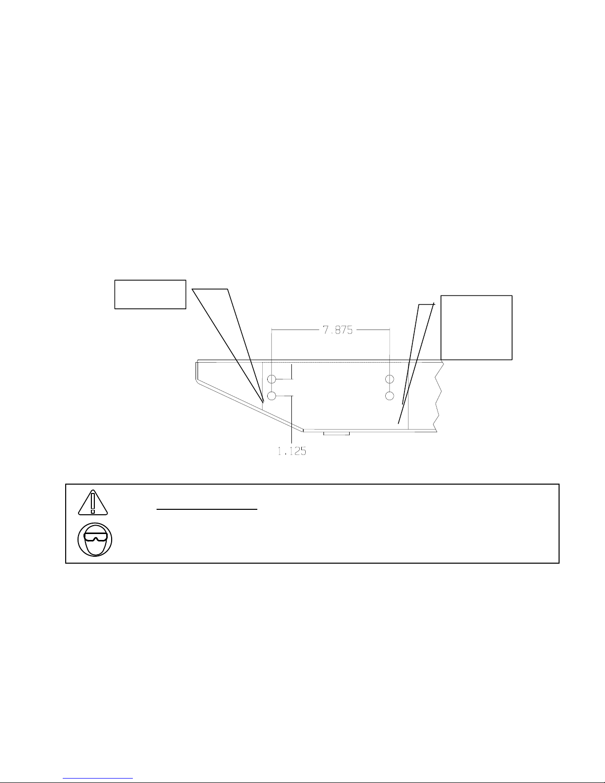
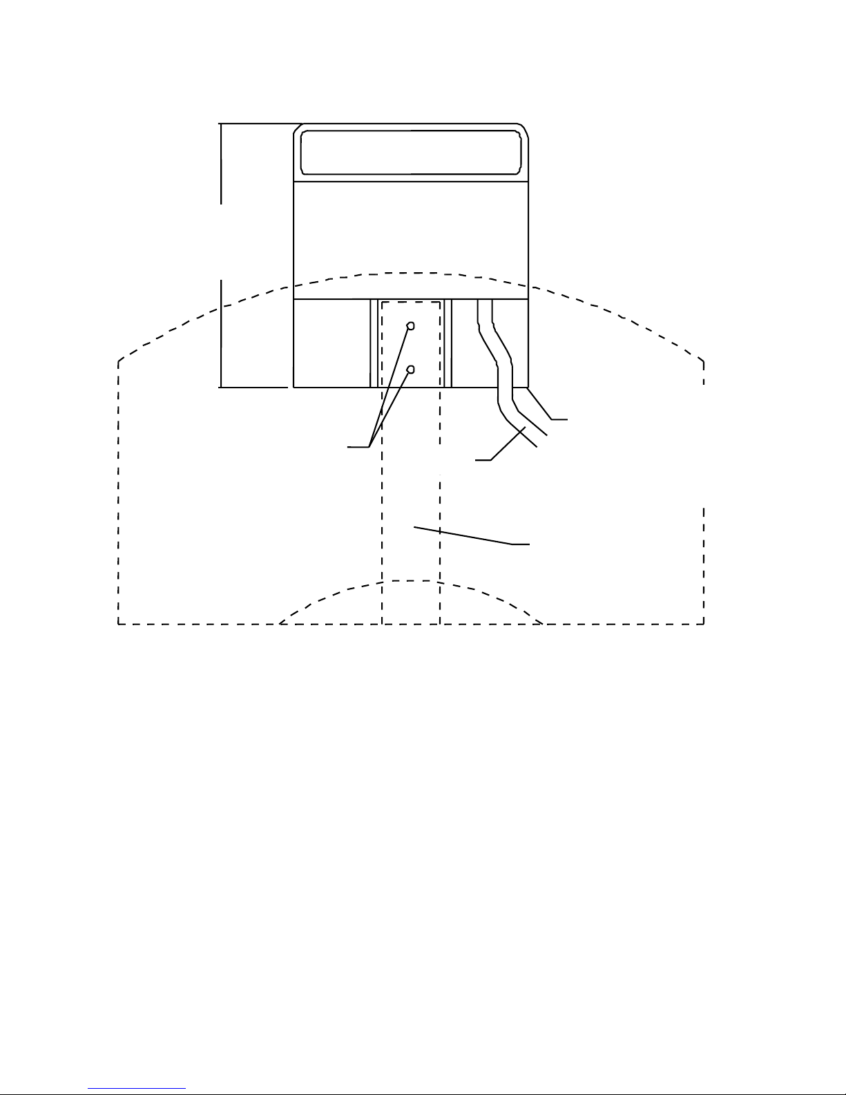
3. On 97-01 TJ models, some of the rear 8 frame holes may not be in the frame.
These holes are the inner four, two on each side of vehicle. They must be drilled to
7/16”. Use figure 2 to locate these holes.
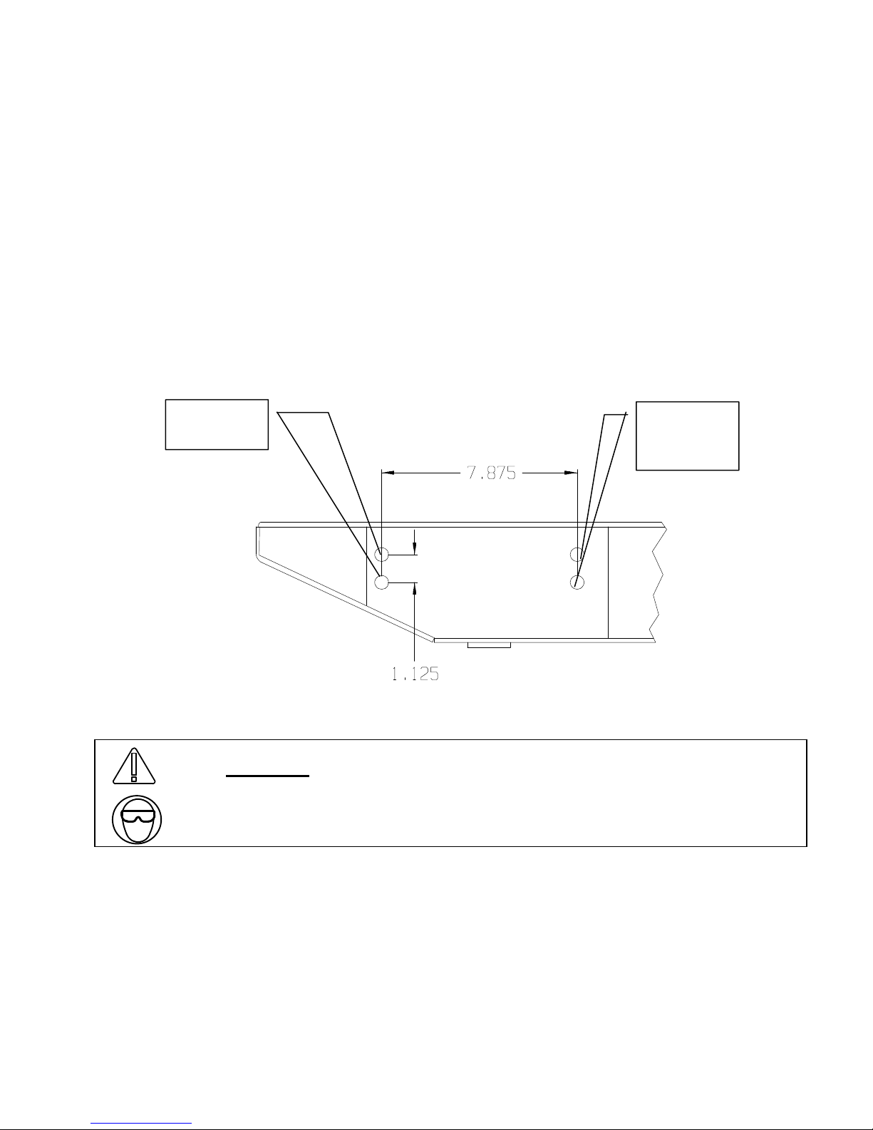
NOTE: Some TJ model vehicles may not have all 8 mounting locations on the
rear frame area. If not all 8 locations are in the frame, measure the supplied
bumper mounting points and match these measurements on the frame. Drill the
frame holes to 7/16”. See Figure 1.
HOLES
EXIST
HOLES
MAY NOT
EXIST
Figure 1
WARNING
Drilling operations can cause flying metal chips. WEAR SAFETY
GOGGLES. Flying metal chips can cause eye injury.
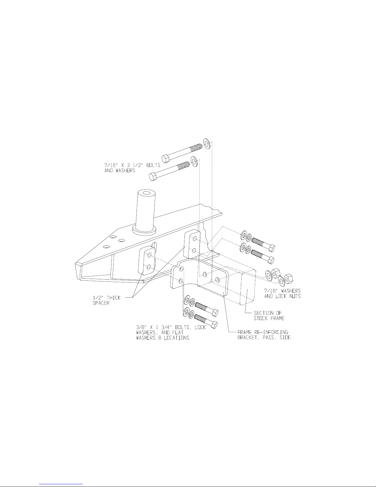
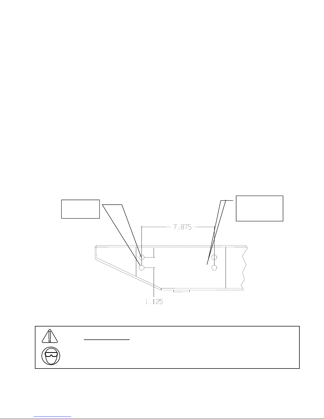
4. Place the new bumper against the back of the vehicle frame. Using the 3/8”
hardware provided, insert a bolt, lock washer, and washer through the appropriate
frame stiffener, rear frame section, ½” thick spacer (on CJ models) OR ¼” thick
spacer on YJ/TJ models, and start into the bumper. On CJ models, use the 3/8” x 13/4” bolts on the all eight rear frame holes. On YJ/TJ models, use 3/8” x 1-3/4” bolts
in the four outer hole locations and the 3/8” x 1-1/2” bolts on the four inner hole
locations. See Figure 2 or 3 depending on vehicle. Do not tighten bolts at this
time.
Page 2 63398 D2
Page 3
Note: It will be easier to get a bolt started on each side and then insert the spacers
between the mating surfaces of the bumper and frame. Slide one spacer up in
between the bumper and frame and start both top and bottom bolts. Then move to
the next locations and repeat the insertion of the spacer. Repeat this for all of the
rear frame locations.
On some TJ and YJ models, it may be necessary to loosen the gas tank skid plate to
allow for enough hand room to access the inner bolt hole locations.
Note: On some CJ models it may be necessary to use additional spacers to prevent
interference between the tire carrier and the tailgate hinges.
Figure 2, CJ VEHICLE, PASSENGER’S SIDE SHOWN,
Page 3 63398 D2
DRIVER’S SIDE OPPOSITE
Page 4
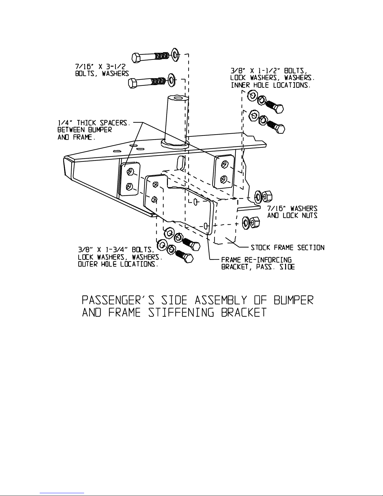
Figure 3, YJ and TJ VEHICLES, PASSENGER’S SIDE SHOWN,
DRIVER’S SIDE OPPOSITE, TJ FRAME STIFFENING BRACKETS
SHOWN, YJ HAS SAME SPACERS AND HARDWARE, BUT WITH
DIFFERENT FRAME STIFFENING BRACKET.
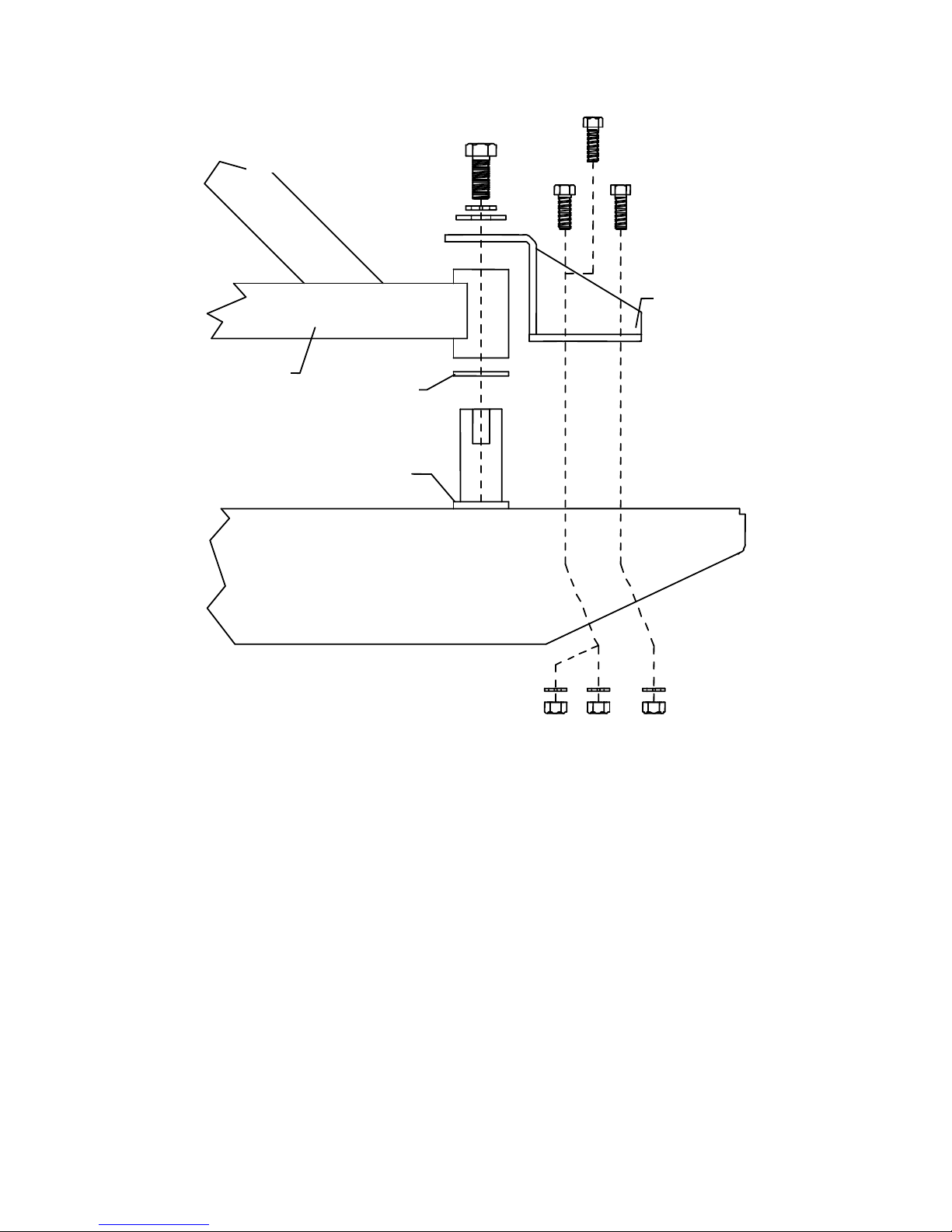
5. Install the tire carrier to bumper. This must be done before tightening of the eight
frame bolts. If installing on TJ model, remove the plastic license plate mount from
the vehicle, it will be trimmed slightly in the bottom corner later. If installing on TJ
and YJ models, it is necessary to remove all of the factory rubber tailgate bumpers
except the upper one on the driver’s side. Place the nylon washer over the post in
the bumper and slide it all the way down. Place the round tube end of the tire carrier
on the post sticking up out of the passenger’s side of the bumper and slide it all the
way down. See Figure 4.
Page 4 63398 D2
Page 5
6. Once the tire carrier is installed on the post in the bumper, finger tighten all eight
bolts that mount the bumper to the frame. Then, insert the single oblong hole
spacers between the bottom of the frame and the bottom tabs on the bumper. Insert
the 7/16” x 1 ½” bolts, lock washers and washers through the bottom tabs on the
bumper and the spacer and finger tighten.
7. Once all of the fasteners are finger tight, adjust bumper position if necessary.
Tighten the 3/8” fasteners to 30-34 ft/lbs and the 7/16” fasteners to 46-50 ft/lbs.
8. Using a drill and 7/16” bit, drill through the inner frame rail using the stiffening
bracket and existing outer frame holes on the out side of frame. A good precaution
would be to place a piece of metal between the inner frame rail and the gas to
prevent from damaging anything on the inside of the frame rails. Checks to see if
any wires or lines are attached in the drilling locations. If lines or wires are found,
temporarily move them out of the way during the drilling process. Repeat this for
the other side of vehicle. See Figure 2 or 3 depending on vehicle.
WARNING
Drilling operations can cause flying metal chips. WEAR SAFETY
GOGGLES. Flying metal chips can cause eye injury.
9. Insert the 7/16” x 4” bolts and flat washers through the frame stiffener bracket and
frame rail and finger tighten using the supplied 7/16” hardware. Torque the 7/16”
hardware to 46-50 ft/lbs. See Figure 2 or 3 depending on vehicle.
10. Install the post support bracket to the bumper. Using the supplied 5/8 x 1 ½” bolt,
lock washer, and washer, hand tighten the bracket to the post. Then install the 3
supplied 7/16 x 1 ½” bolts and washers through the support bracket and the bumper.
Install a 7/16” washer, lock washer and nut on each bolt inside the bumper. It may
be necessary to use a magnet or needle nose pliers to install the nuts and washers
onto the bolts. On CJ models it may be necessary to install the two bolts that are
rd
furthest forward and match drill the 3
rear hole. This is due to the tight packaging
of the bumpers ends. See Figure 4.
Page 5 63398 D2
Page 6
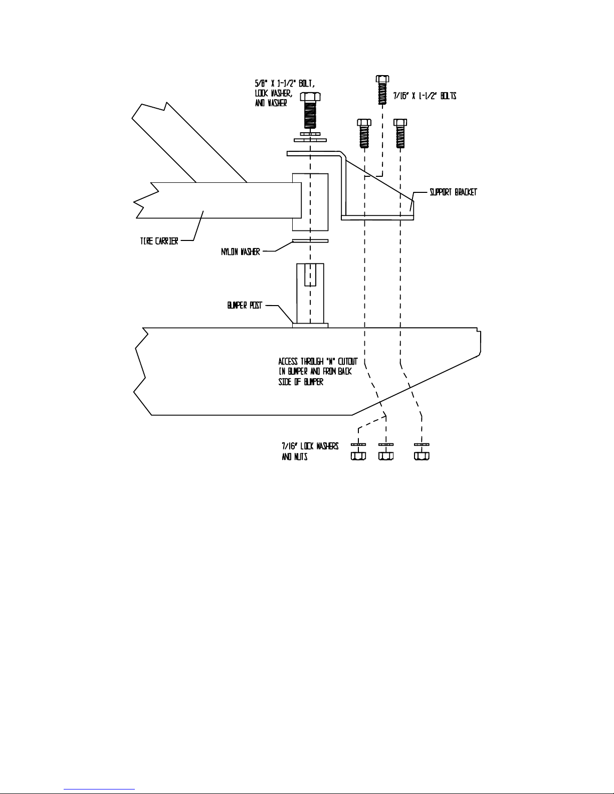
Figure 4
11. Once the tire carrier and support bracket are assembled, torque the 7/16” hardware
to 46-50 ft/lbs and the 5/8” hardware to 70-90 ft/lbs.
12. Install the supplied zerk fitting into the supplied hole in the tire carrier pivot tube.
Once installed, use a grease gun to lubricate the pivot.
13. Close the tire carrier. Install the spare tire to the tire mounting bracket. Use the
three wheel studs supplied. The wheel studs can be pressed in or use a vise and
hammer to install them. They can also be installed by installing the tire and use lug
nuts to tighten and the studs will pull in when tightening the studs.
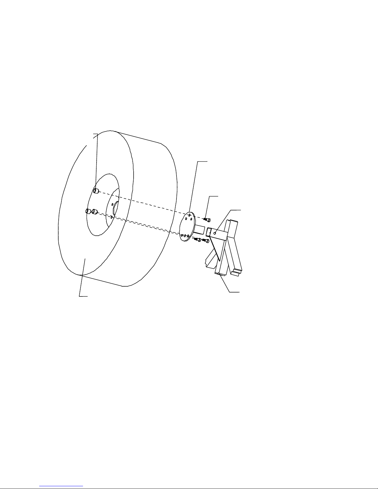
14. Once the studs are installed, attach the tire to the mounting bracket. Slide the tire
mounting bracket, on the backside of the wheel, into the bracket mounting tube on
the tire carrier. With the tire pushed all the way in, mark the tire mounting bracket
using the supplied hole in the tire carrier tube. Remove the tire and tire mounting
bracket from the carrier. See Figure 5.
Page 6 63398 D2
Page 7
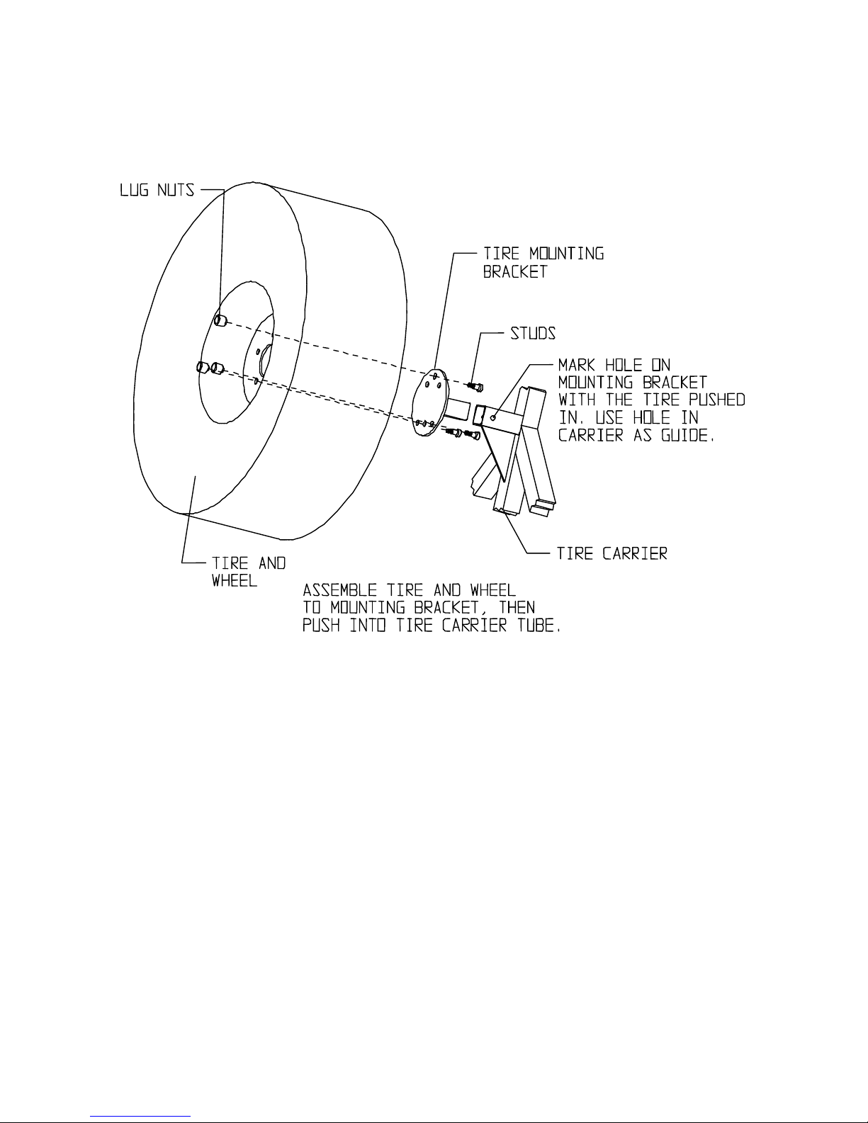
Figure 5
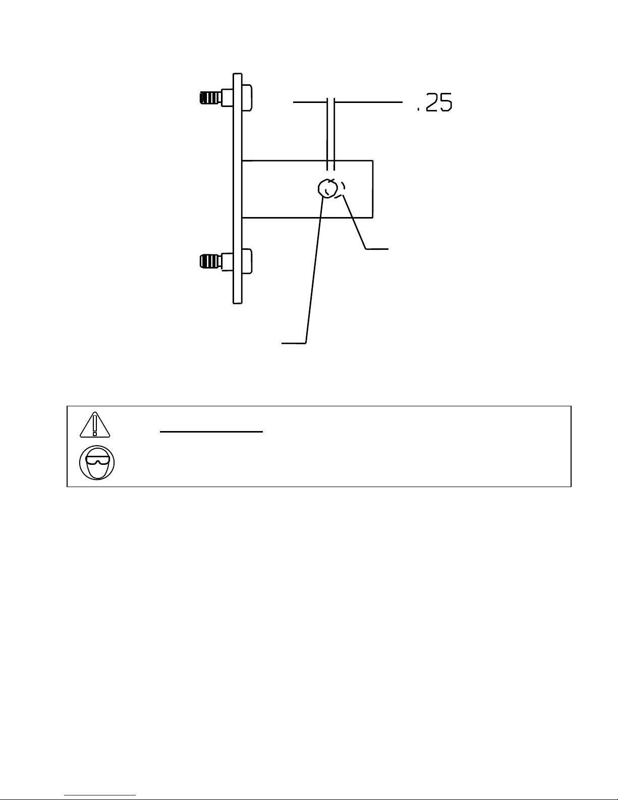
15. Remove the tire and wheel from the mounting bracket. Using the marked location
on the tire mounting bracket in the previous step, measure ¼” back toward the wheel
mounting surface. This will give the tire pre-load when mounted. Using a ½” drill bit,
drill a hole through both sides of the tire mounting bracket at the marked location.
Be sure to re-mark the hole ¼” closer to the tire mounting surface for pre-load. See
Figure 6.
Page 7 63398 D2
Page 8
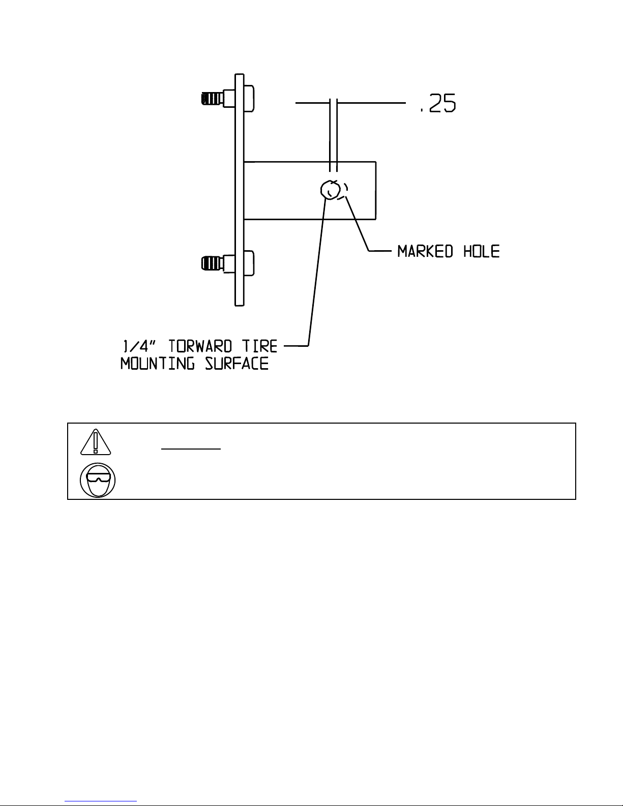
Figure 6
WARNING
Drilling operations can cause flying metal chips. WEAR SAFETY
GOGGLES. Flying metal chips can cause eye injury.
16. After drilling the hole in step 17, slip the tire mounting bracket into the tube on the
tire carrier. Using the supplied ½” x 3” bolt, washers, and lock nut, bolt the mounting
bracket to the carrier. Torque the ½” bolt to 55-60 ft/lbs.
17. Mount the tire and wheel to the tire carrier with lug nuts. Locking lugs can be used
to prevent theft.
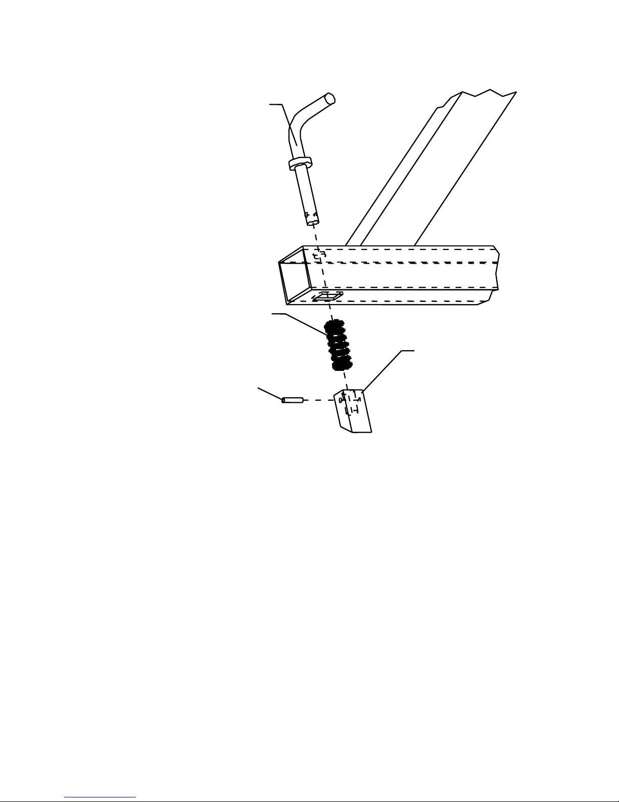
18. Assemble the latch mechanism. Insert the handle through the hole in the top of the
tire carrier tube. Then insert the supplied coil spring through the rectangular hole in
the bottom of the tube. Insert the striker latch through the same rectangular hole.
The handle will be inserted into the ½” diameter hole in the striker. Line up the small
cross-holes in the handle and the striker. Insert the roll pin, by tapping it with a
hammer, through the hole in the striker and the handle. It should be flush on both
sides of the striker when installed fully. See Figure 7 for exploded view of
assembly.
Page 8 63398 D2
Page 9
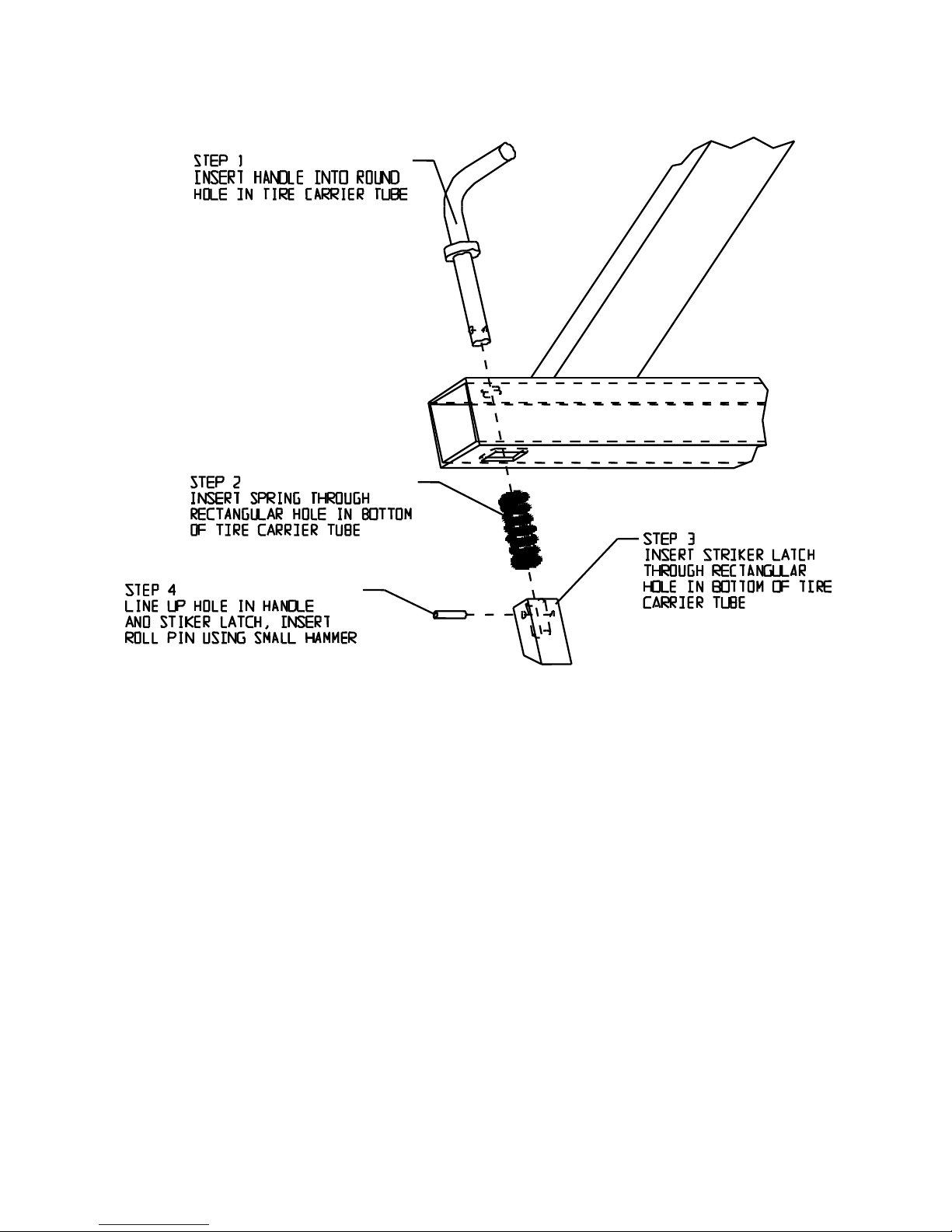
FIGURE 7, EXPLODED VIEW OF LATCH ASSEMBLY.
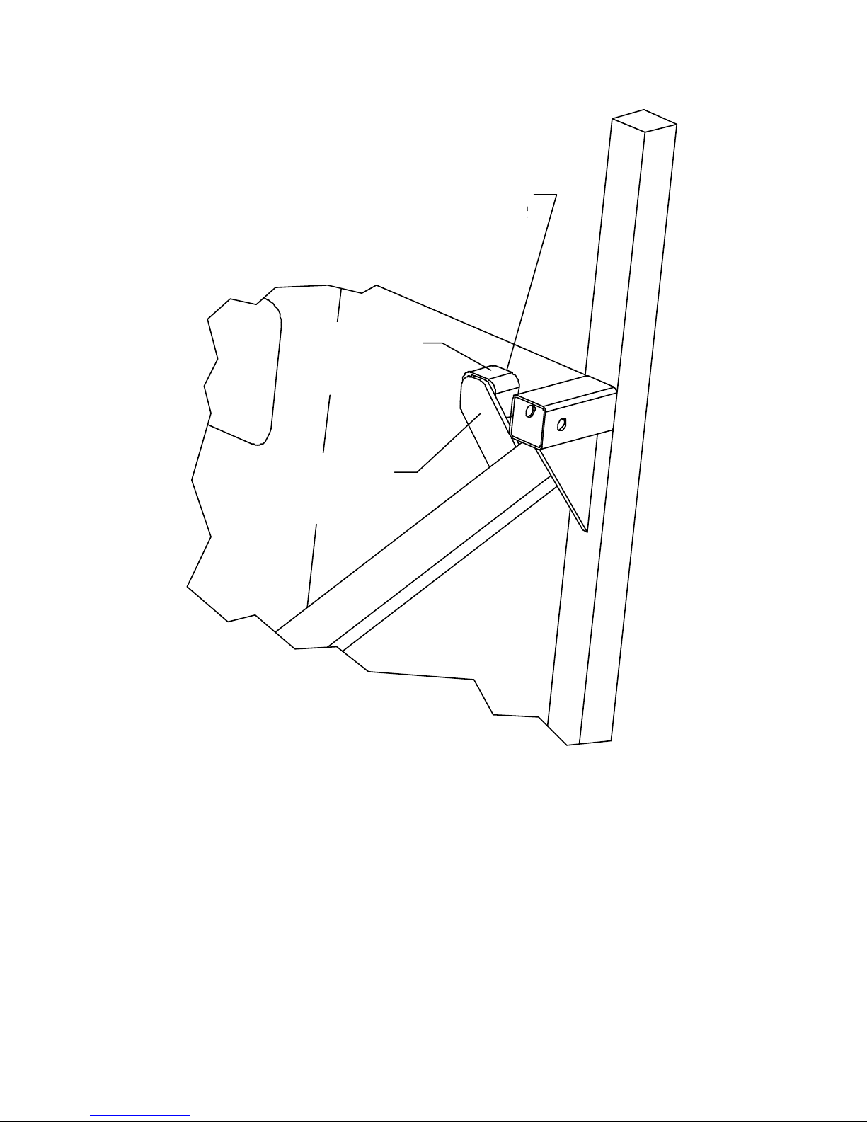
19. There is a flat plate welded to the tire carrier framework. A rubber bumper should be
mounted to either the flat plate or the tailgate to prevent the tire carrier from rocking
back and forth on rough terrain on CJ models, see step 24 for CJ installation. The
TJ and YJ have these rubber bumpers mounted on the tailgate already. It may be
necessary to shim the driver’s side top bumper out away from the tailgate to have
slight pressure on the flat plate when the assembly is in the closed position. See
Figure 8.
Page 9 63398 D2
Page 10
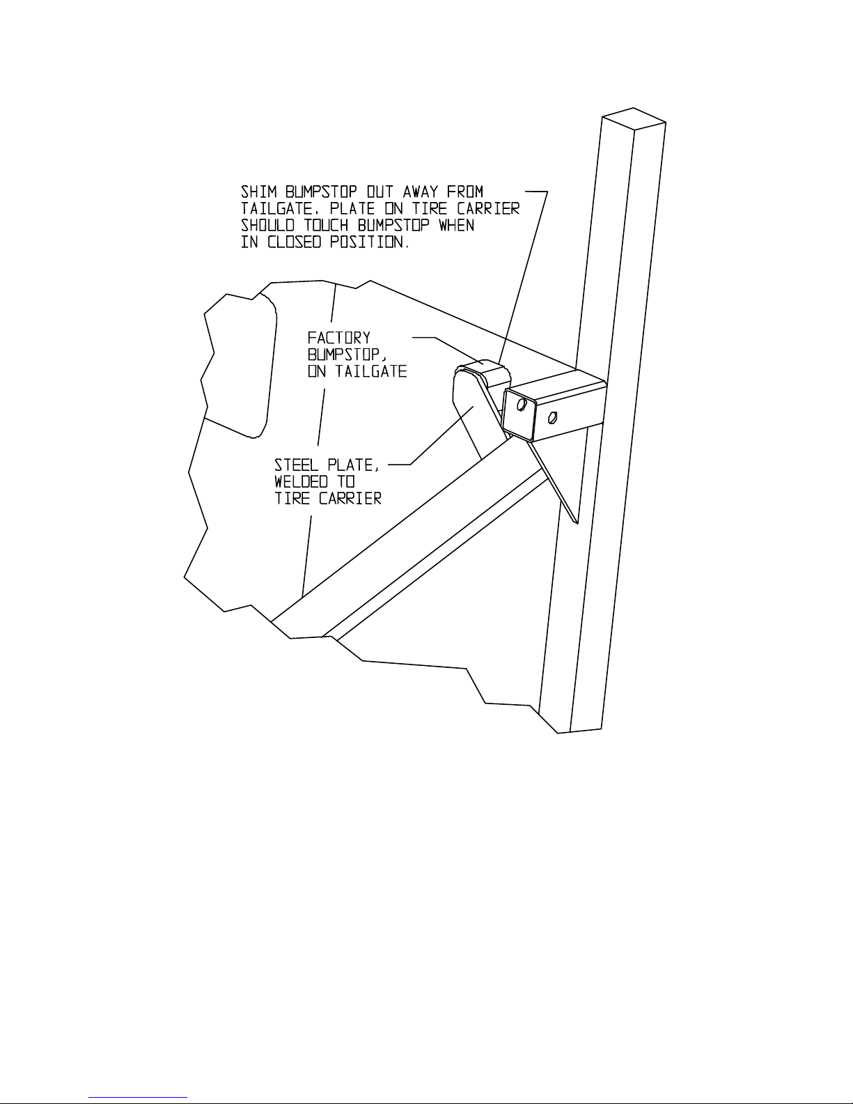
Figure 8, Factory Tailgate Bumpstop, TJ and YJ models.
20. A CB antenna may be mounted to either the bumper or tire carrier. The reception of
the CB should be better if mounted to the bumper. The tire carrier may not give a
sufficient ground. Many customers have just drilled a hole on one side of the
bumper at the ends.
Page 10 63398 D2
Page 11
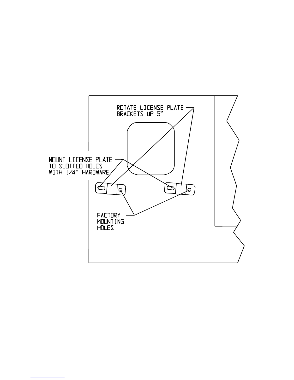
21. On TJ models, using the two supplied brackets, mount the brackets to the body with
the factory screws. The end of the bracket with the standard hole is mounted to the
body. The slotted holes are used for mounting the license plate. Align the two
brackets so they are rotated up 5 degrees and going away from the tailgate. Tighten
the factory screws. Using the ¼” hardware provided, insert a bolt with flat washer
through the license plate and the bracket and finger tighten with a lock washer and
nut. Repeat this for both brackets. See figure 9.
FIGURE 9, MOUNTING BRACKETS FOR LICENSE ON TJ MODELS ONLY
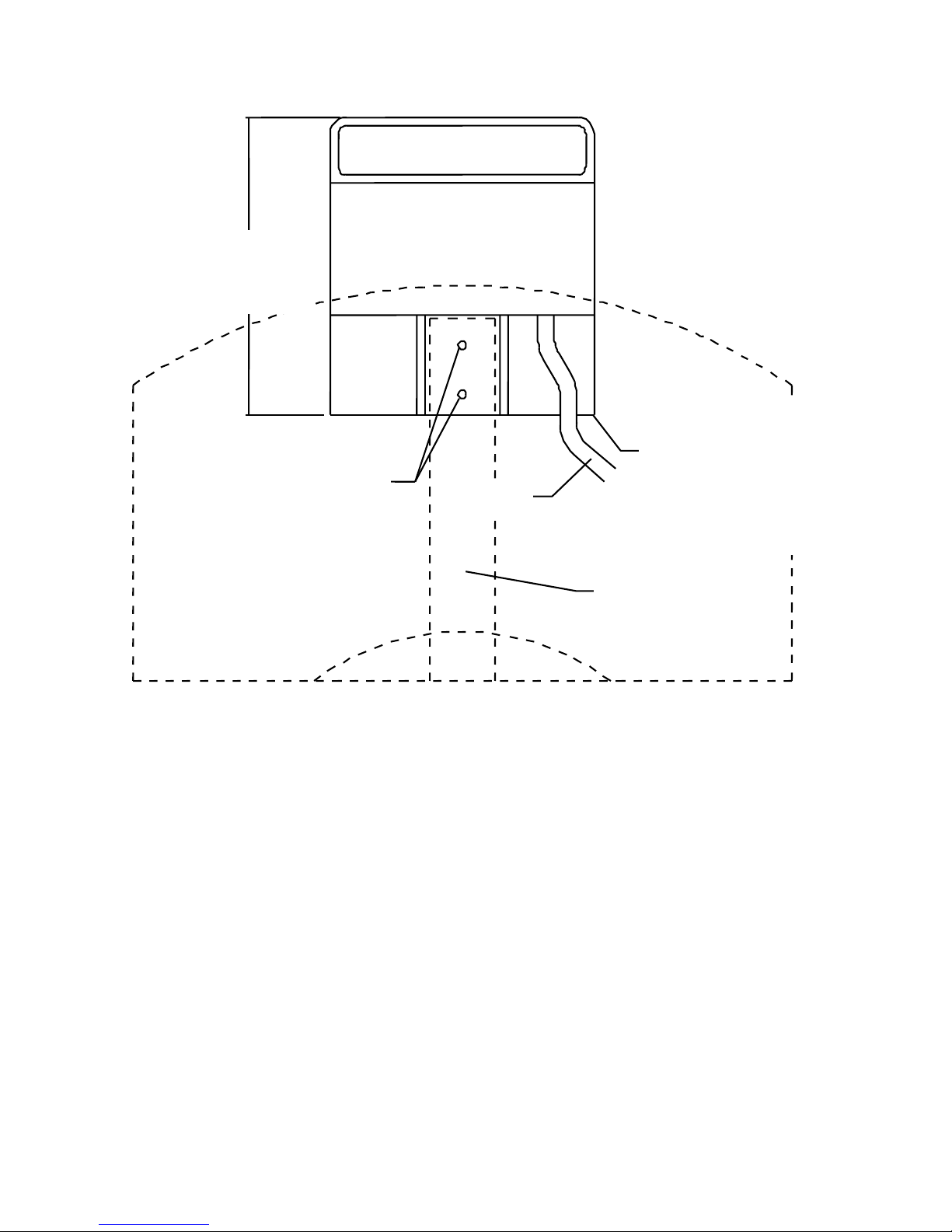
22. On TJ and YJ vehicles with a 3rd brake light, it will be necessary to re-install the light.
This can be easily done by cutting the Original Bracket and mounting it to the vertical
post on the new tire carrier. Two small screws are supplied for mounting it. See
Figure 10.
Page 11 63398 D2
Page 12
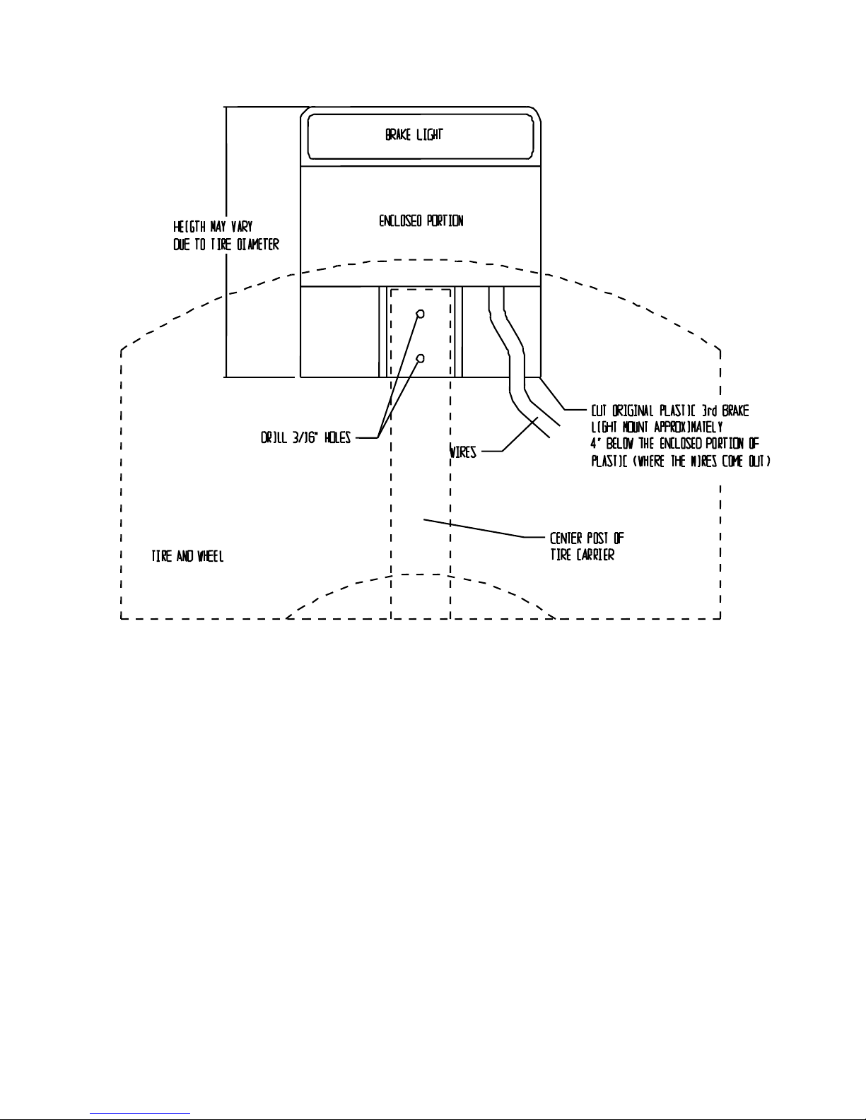
Figure 10, 3rd BRAKE LIGHT MOUNTING
23. On CJ vehicles it is required to install a rubber tailgate bumper. The Chrysler/Jeep
P/N is 55013350 and is available at Jeep Dealer Parts Departments. A picture is
included for reference. Depending on the alignment of the body to frame on your
specific vehicle, it may be necessary to shim the rubber bumper out from the tailgate
or sand it down, more than likely it will be sanded down.
NOTE: Very slight pressure should be on the rubber bumper when the tire
carrier is in the closed position. Due to vehicles being vastly different and
very old, be sure that the tire carrier is vertical when it is in the closed position
and there is slight pressure on the tailgate bumper. This may require that
more pressure be added to the tailgate bumper to get a vertical reading in the
closed position. This will verify that the carrier will not rattle on the tailgate
hinges.
With the tire carrier in the closed position, try to slide the rubber bumper in between
the tailgate and welded tab on the tire carrier. In the photo below the bottom edge of
the rubber bumper has been sanded off at a 45-degree angle to allow the rubber
Page 12 63398 D2
Page 13

bumper to be lower on the tailgate. Once the correct position is found, mark the
tailgate. Open the tire carrier and mark the hole in the center of the rubber bumper.
The rubber bumper can either be bolted on through the tailgate or sheet metal
screwed to the tailgate.
Photo of Rubber Bumper on CJ tailgate.
WARNING
Drilling operations can cause flying metal chips. WEAR SAFETY
GOGGLES. Flying metal chips can cause eye injury.
24. Once all of the above steps are completed, recheck all of the mounting bolts for
proper toque.
25. Periodically fill the grease zerk on the tire carrier to prevent corrosion and binding.
Page 13 63398 D2
Page 14

INSTRUCTIONS D’INSTALLATION
PORTE-ROUE ET PARE-CHOCS WARN
Les directives suivantes comprennent des indications intitulées REMARQUE,
MISES EN GARDE et AVERTISSEMENT. Chacune d'entre elles comporte un
objectif bien précis : les REMARQUES donnent des renseignements
additionnels qui aident à accomplir une procédure. Les MISES EN GARDE
comprennent des mesures de sécurité signalant un danger potentiel qui, s’il n’est
pas évité, peut entraîner des blessures légères ou modérées. La MISE EN
GARDE sert aussi à signaler une utilisation dangereuse. AVERTISSEMENT
présente des consignes de sécurité soulignant un danger potentiel qui, s’il n’est
pas évité, peut entraîner des blessures graves. MISE EN GARDE et
AVERTISSEMENT identifient un danger, indiquent comment l'éviter et montrent
ses conséquences possibles si on l'ignore. TRAVAILLEZ PRUDEMMENT!
REMARQUE : Des pièces d’espacement et des boulons supplémentaires sont
fournis dans un sachet séparé pour les modèles Jeep CJ. Pour certaines
applications, il faut des pièces d’espacement supplémentaires pour passer
au-dessus des charnières et des loquets des toits amovibles, en raison des
écarts entre le cadre et la carrosserie.
REMARQUE : Cette installation peut nécessiter de percer sur certains modèles. Il
faudra éventuellement percer au travers du côté du cadre si les trous
n'existent pas déjà.
REMARQUE : Pour les modèles dotés d’un toit amovible, il faut parfois faire
tourner la poignée de la vitre arrière de 90° pour éviter toute interférence
avec le porte-roue.
Généralités :
Instructions pour CJ, YJ, TJ
Ne convient pas à des pneus de dimensions supérieures à 35 x 15,50, 36 x 12,50
ou 68 kg.
Il faudra démonter le pare-chocs et le porte-roue d'origine pour installer le nouveau
porte-roue.
Il faudra déplacer le 3
emplacement peut varier en fonction des dimensions du pneu. Cf. instructions.
Il faudra 3 écrous de roue ½ po.-20 pour monter la roue de secours sur le porte-
roue.
Il faudra 1 pièce réf. 55013350 pour les modèles CJ. Il s’agit d’une butée de hayon
d’un modèle TJ qui permettra d’éliminer les cliquetis ou les vibrations.
ème
feu de freinage pour pouvoir utiliser ce porte-roue. Son
Page 14 63398 D2
Page 15
Consignes étape par étape :
1. Démontez le pare-chocs et le porte-roue d’origine. Sur les modèles TJ, démontez la
plaque d’immatriculation et son support du châssis. Conservez les fixations.
2. Sortez le porte-roue, le pare-chocs et les fixations de leur carton.
3. Sur les modèles TJ de 97-01, certains des 8 trous du cadre arrière peuvent ne pas
se trouver dans le cadre. Il s’agit des quatre trous intérieurs, deux de chaque côté
du véhicule. Il faut les percer à 7/16 po. Utilisez la figure 2 pour déterminer
l'emplacement de ces trous.
REMARQUE : Sur certains modèles TJ, les 8 trous de fixation ne sont pas
toujours tous dans le cadre arrière. Si c’est le cas, mesurez les points de fixation
du pare-chocs fourni et faites-les correspondre sur le cadre. Percez les trous
dans le cadre à 7/16 po. Voir la figure 1.
TROUS
PRÉSENTS
LES TROUS
PEUVENT
NE PAS
ÊTRE
PRÉSENTS
Figure 1
AVERTISSEMENT
Des éclats métalliques peuvent être projetés durant le perçage. PORTER
DES LUNETTES DE SÉCURITÉ. Les éclats métalliques peuvent causer
des lésions oculaires.
4. Placez le nouveau pare-chocs contre l’arrière du cadre du véhicule. Au moyen des
fixations de 3/8 po. fournies, insérez un boulon, une rondelle de blocage et une
rondelle au-travers du renfort de cadre approprié, de la section du cadre arrière,
d’une pièce d’espacement d’une épaisseur de ½ po. (sur les modèles CJ) OU d'une
épaisseur de ¼ po. sur les modèles YJ/TJ et passez dans le pare-chocs. Sur les
modèles CJ, utilisez les boulons 3/8 po. x 1-3/4 po. dans les 8 trous du cadre
arrière. Sur les modèles YJ/TJ, utilisez les boulons 3/8 po. x 1-3/4 po. dans les
quatre trous extérieurs et les boulons 3/8 po. x 1-1/2 po. dans les quatre trous
intérieurs. Voir la Figure 2 ou 3 en fonction du véhicule. Ne pas serrer les
boulons pour l'instant.
Page 15 63398 D2
Page 16

Remarque : Il sera plus facile de commencer par un boulon de chaque côté, puis
d’insérer les pièces d’espacement entre les surfaces d’accouplement du pare-chocs
et du cadre. Faites glisser une pièce d’espacement entre le pare-chocs et le cadre
et commencez à serrer les boulons du haut et du bas. Puis passez aux autres
boulons et répétez l’insertion de la pièce d’espacement. Répétez cette opération
pour tous les boulons du cadre arrière.
Sur certains modèles TJ et YJ, il peut s'avérer nécessaire de desserrer la plaque de
protection du réservoir de carburant pour permettre de pouvoir passer la main afin
d'accéder aux trous de boulon intérieurs.
Remarque : Sur certains modèles CJ, il peut être nécessaire d’utiliser des pièces
d’espacement supplémentaires pour éviter une interférence entre le porte-roue et
les charnières du hayon.
BOULONS 7/16" x 3 1/2"
ET RONDELLES
RONDELLE
D'ESPACEMENT
BOULONS 3/8" X 1 3/4", RONDELLES DE BLOCAGE ET
RONDELLES PLATES 8 EMPLACEMENTS
Figure 2, MODÈLE CJ, CÔTÉ PASSAGER ILLUSTRÉ,
OPPOSÉ CÔTÉ CONDUCTEUR
Page 16 63398 D2
RONDELLES 7/16" ET
ÉCROUS DE BLOCAGE
SECTION DU
CADRE DE
SUPPORT DE RENFORT DU
CADRE, CÔTÉ PASSAGER
Page 17

BOULONS 7/16" x 31/2", RONDELLES
PIÈCES
D’ESPACEMENT 1/4"
ENTRE LE PARECHOC ET LE CADRE
BOULONS 3/8" x 1-1/2", RONDELLES DE
BLOCAGE, RONDELLES
EMPLACEMENTS DES TROUS
INTÉRIEURS
RONDELLES
7/16" ET ÉCROUS
DE BLOCAGE
BOULONS 3/8" x 1-3/4",
RONDELLES DE BLOCAGE,
RONDELLES
EMPLACEMENTS DES TROUS
EXTÉRIEURS
SUPPORT DE RENFORT
DU CADRE, CÔTÉ
PASSAGER
SECTION DU CADRE
DE SÉRIE
ASSEMBLAGE CÔTÉ PASSAGER DU PARE-CHOC ET DU
SUPPORT DE RENFORT DU CADRE
Figure 3, MODÈLES YJ et TJ, CÔTÉ PASSAGER ILLUSTRÉ, OPPOSÉ
CÔTÉ CONDUCTEUR, SUPPORTS DE RENFORT DU CADRE TJ
ILLUSTRÉS, YJ A LES MÊMES PIÈCES D’ESPACEMENT ET
FIXATIONS, MAIS AVEC UN SUPPORT DE RENFORT DE CADRE
DIFFÉRENT.
5. Installez le porte-roue sur le pare-chocs. Il faut procéder à cette étape avant de
serrer les huit boulons du cadre. Pour une installation sur un modèle TJ,
démontez le support en plastique de la plaque d'immatriculation du véhicule. Son
coin inférieur sera légèrement découpé ultérieurement. Pour une installation sur
les modèles TJ et YJ, il faut démonter toutes les butées arrière en caoutchouc
d’origine, sauf la butée supérieure côté conducteur. Placez la rondelle en nylon sur
la tige du pare-chocs et faites-la glisser jusqu’en bas. Placez l’extrémité tubulaire
Page 17 63398 D2
Page 18
ronde du porte-roue sur la tige qui dépasse le pare-chocs côté passager et faites-la
glisser jusqu’en bas. Voir la figure 4.
6. Une fois que le porte-roue est installé sur la tige du pare-chocs, serrez à la main les
huit boulons qui fixent le pare-chocs au cadre. Puis insérez la pièce d'espacement
à trou rectangulaire entre le bas du cadre et les languettes inférieures du parechocs. Insérez les boulons de 7/16 po. x 1 ½ po., les rondelles de blocage et les
rondelles au travers des languettes inférieures du pare-chocs et de la pièce
d’espacement et serrez à la main.
7. Une fois que toutes les fixations sont serrées à la main, ajustez la position du parechocs s’il y a lieu. Serrez les fixations de 3/8 po. entre 41 et 47 Nm et les fixations
7/16 po. entre 62 et 68 Nm.
8. Au moyen d’une perceuse et d’une mèc he de 7/16 po., percez au travers du rail du
cadre intérieur, en utilisant le support de renfort et les trous existants du cadre
extérieur à l'extérieur du cadre. Il serait souhaitable de placer une pièce métallique
entre le rail du cadre intérieur et le réservoir pour éviter tout dommage à l'intérieur
des rails du cadre. Vérifiez si des câbles ou conduites sont fixés aux endroits du
perçage. Si vous trouvez des câbles ou des conduites, déplacez-les provisoirement
pendant le perçage. Répétez cette opération de l’autre côté du véhicule. Voir la
Figure 2 ou 3 en fonction du véhicule.
AVERTISSEMENT
Des éclats métalliques peuvent être projetés durant le perçage. PORTER
DES LUNETTES DE SÉCURITÉ. Les éclats métalliques peuvent causer
des lésions oculaires.
9. Insérez les boulons 7/16 po. x 4 po. et les rondelles plates au travers du renfort et
du rail du cadre et serrez à la main au moyen de la clé 7/16 po. fournie. Serrez les
fixations 7/16 po. entre 62 et 68 Nm. Voir la Figure 2 ou 3 en fonction du
véhicule.
10. Installez le support de la tige sur le pare-chocs. Au moyen du boulon 5/8 x 1 ½ po.,
de la rondelle de blocage et de la rondelle, serrez le support sur la tige à la main.
Puis installez les 3 boulons 7/16 x 1 ½ po. et rondelles fournis au-travers du support
et du pare-chocs. Installez une rondelle 7/16 po., une rondelle de blocage et un
écrou sur chaque boulon à l’intérieur du pare-chocs. Il peut s’avérer nécessaire
d’utiliser un aimant ou une pince à bec effilé pour installer les écrous et les rondelles
sur les boulons. Sur les modèles CJ, il peut s’avérer nécessaire d’installer les deux
boulons qui sont le plus vers l’avant et de percer le 3
ème
trou en le faisant
correspondre à l’emplacement voulu. Cela est dû au fait que les extrémités du parechocs sont très compactes. Voir la figure 4.
Page 18 63398 D2
Page 19

PORTEROUE
BOULONS 5/8" x 1-1/2",
RONDELLE DE BLOCAGE
ET RONDELLE
RONDELLE
EN NYLON
TIGE DE BUTÉE
ACCÈS AU TRAVERS DE LA
DÉCOUPE EN « W » DU PARECHOCS ET DEPUIS L’ARRIÈRE
DU PARE-CHOCS
BOULONS 7/16" x 1-1/2"
SUPPORTS
RONDELLES 7/16"
ET ÉCROUS
Figure 4
11. Une fois que le porte-roue et le support sont assemblés, serrez les fixations de 7/16
po. entre 62 et 68 Nm et les fixations de 5/8 po. entre 95 et 122 Nm.
12. Installez le graisseur fourni dans le trou réservé à cet usage dans le tube pivotant du
porte-roue. Une fois installé, utilisez une pompe de graissage pour lubrifier le pivot.
13. Fermez le porte-roue. Installez la roue de secours sur le support de roue. Utilisez
les trois goujons fournis. Les goujons peuvent être enfoncés ou bien utilisez un étau
et un marteau pour les installer. Ils peuvent aussi être montés en installant la roue
et en utilisant les écrous pour serrer. Les goujons se rétracteront au fur et à mesure
du serrage des écrous.
Page 19 63398 D2
Page 20

14. Une fois les goujons installés, fixez la roue sur le support. Faites glisser le support
de roue, à l’arrière de la roue, dans le tube de montage du support sur le porte-roue.
Avec la roue enfoncée le plus loin possible, marquez le support de montage de la
roue au moyen du trou fourni dans le tube du porte-roue. Retirez la roue et son
support de montage du porte-roue. Voir la figure 5.
ÉCROUS DE ROUE
SUPPORT DE
MONTAGE DE ROUE
GOUJONS
MARQUEZ LE TROU SUR LE
SUPPORT DE MONTAGE
AVEC LA ROUE ENFONCÉE.
UTILISEZ LE TROU DU
PORTE-ROUE COMME
GUIDE
PNEU ET
ROUE
MONTEZ LE PNEU ET LA ROUE SUR
LE SUPPORT DE MONTAGE, PUIS
POUSSEZ DANS LE TUBE DU PORTEROUE
PORTE-ROUE
Figure 5
15. Retirez le pneu et la roue du support de montage. Au moyen de l’emplacement
repéré sur le support de montage de la roue à l’étape précédente, mesurez ¼ po.
(0,6 cm) en arrière, vers la surface de montage de la roue. Cela donnera la
précharge du pneu une fois monté. Au moyen d’une mèche de ½ po., percez un
trou au travers des deux côtés du support de montage de la roue à l’endroit marqué.
N’oubliez pas de marquer à nouveau le trou ¼ po. (0,6 cm) plus près de la surface
de montage du pneu pour la précharge. Voir la figure 6.
Page 20 63398 D2
Page 21
TROU MARQUÉ
1/4" VERS LA SURFACE
DE MONTAGE
Figure 6
AVERTISSEMENT
Des éclats métalliques peuvent être projetés durant le perçage. PORTER
DES LUNETTES DE SÉCURITÉ. Les éclats métalliques peuvent causer
16. Après avoir percé le trou à l'étape 17, faites glisser le support de montage de la roue
sur le tube du porte-roue. Au moyen du boulon ½ po. x 3 po., des rondelles et de
l’écrou de blocage fournis, boulonnez le support de montage sur le porte-roue.
Serrez le boulon ½ po. entre 74 et 81 Nm.
17. Montez le pneu et la roue sur le porte-roue au moyen des écrous de roue. Vous
pouvez utiliser des écrous antivol.
18. Montez le mécanisme du loquet. Insérez la poignée dans le trou en haut du tube du
porte-roue. Puis insérez le ressort hélicoïdal fourni au travers du trou rectangulaire
en bas du tube. Insérez la gâche du loquet au travers du même trou rectangulaire.
La poignée sera insérée dans le trou d’un diamètre de ½ po. dans la gâche. Alignez
les petits contre-trous de la poignée et de la gâche. Insérez la goupille élastique, en
la frappant avec un marteau, au travers du trou de la gâche et de la poignée. Elle
ne doit pas dépasser de chaque côté de la gâche une fois correctement installée.
Cf. Figure 7 pour une vue explosée de l’ensemble.
des lésions oculaires.
Page 21 63398 D2
Page 22

PREMIÈRE ÉTAPE :
INSÉREZ LA POIGNÉE DANS LE
TROU ROND DU TUBE DU
PORTE-ROUE
DEUXIÈME ÉTAPE :
INSÉREZ LE RESSORT AUTRAVERS DU TROU
RECTANGULAIRE EN BAS
DU TUBE DU PORTE-ROUE
QUATRIÈME ÉTAPE :
ALIGNEZ LE TROU DE LA
POIGNÉE ET DE LA GÂCHE DU
LOQUET, INSÉREZ LA
GOUPILLE ÉLASTIQUE AU
MOYEN D’UN PETIT MARTEAU
TROISIÈME ÉTAPE :
INSÉREZ LA GÂCHE DU
LOQUET AU-TRAVERS DU
TROU RECTANGULAIRE
EN BAS DU TUBE DU
PORTE-ROUE
FIGURE 7, VUE EXPLOSÉE DE L'ENSEMBLE DE LA GÂCHE.
19. Une plaque plate est soudée au cadre du porte-roue. Sur les modèles CJ, il faut
monter une butée en caoutchouc soit sur cette plaque, soit sur le hayon pour éviter
que le porte-pneu ne bascule d'avant en arrière sur des terrains accidentés. Voir
l’étape 24 pour l'installation sur le modèle CJ. Les modèles TJ et YJ sont déjà
équipés de cette butée en caoutchouc sur le hayon. Il peut s’avérer nécessaire de
caler le pare-chocs supérieur côté conducteur pour l’écarter du hayon, afin d’avoir
une légère pression sur la plaque plate une fois que l’ensemble est en position
fermée. Voir la figure 8.
Page 22 63398 D2
Page 23
CALEZ LA BUTÉE EN L’ÉCARTANT DU
HAYON. LA TÔLE DU PORTE-ROUE DOIT
TOUCHER LA BUTÉE EN POSITION FERMÉE
BUTÉE
D’ORIGINE SUR
LE HAYON
TÔLE SOUDÉE
SUR LE PORTEROUE
Figure 8, Butée du hayon d’origine, modèles TJ et YJ.
20. Il est possible de monter une antenne CB sur le pare-chocs ou sur le porte-roue. La
réception de la CB devrait être meilleure avec un montage sur le pare-chocs. Il se
peut que la surface ne soit pas suffisante sur le porte-roue. Souvent, les clients ont
simplement percé un trou d’un côté du pare-chocs, aux extrémités.
Page 23 63398 D2
Page 24

21. Sur les modèles TJ, montez les deux supports fournis sur la carrosserie au moyen
des vis d'origine. L’extrémité du support avec le trou standard est montée sur la
carrosserie. Les trous en forme de fente servent à monter la plaque
d'immatriculation. Alignez les deux supports de sorte à les faire tourner de 5 degrés
vers le haut, côté opposé au hayon. Serrez les vis d’origine. Au moyen des
fixations ¼ po. fournies, insérez un boulon avec une rondelle plate au travers de la
plaque d’immatriculation et du support et serrez à la main avec une rondelle de
blocage et un écrou. Répétez cette opération pour les deux supports. Voir la
Figure 9.
FAITES TOURNER LES SUPPORTS DE
LA PLAQUE D’IMMATRICULATION DE
5° VERS LE HAUT
MONTEZ LA PLAQUE
D’IMMATRICULATION DANS
LES TROUS EN FORME DE
FENTE AU MOYEN DES
FIXATIONS 1/4"
TROUS DE
MONTAGE
D’ORIGINE
FIGURE 9, SUPPORTS DE MONTAGE DE LA PLAQUE D'IMMATRICULATION
POUR LES MODÈLES TJ EXCLUSIVEMENT
ème
22. Sur les véhicules TJ et YJ équipés d’un 3
feu de freinage, il faudra déplacer celuici. Cette opération est facile. Il suffit de couper le support d’origine et de le monter
sur la tige verticale du nouveau porte-roue. Deux petites vis sont fournies à cet
effet. Voir la figure 10.
Page 24 63398 D2
Page 25
LA HAUTEUR PEUT
VARIER EN
FONCTION DU
DIAMÈTRE DU PNEU
PERCEZ DES TROUS
DE 3/16"
FEU DE FREINAGE
ESPACE
CLOS
CÂBLES
DÉCOUPEZ LE SUPPORT DU
ème
FEU DE FREINAGE EN
3
PLASTIQUE D’ORIGINE
ENVIRON 4 po. EN DESSOUS
DE L’ESPACE CLOS DU
PLASTIQUE (OÙ SORTENT
LES CÂBLES)
TIGE CENTRALE DU
PNEU ET ROUE
PORTE-ROUE
Figure 10, MONTAGE DU 3
ème
FEU DE FREINAGE
23. Sur les modèles CJ, il faut installer une butée arrière en caoutchouc. Il s’agit de la
pièce réf. 55013350 Chrysler/Jeep, disponible chez les revendeurs de pièces Jeep.
Une illustration est fournie pour information. En fonction de l’alignement de la
carrosserie et du cadre sur votre véhicule, il peut s’avérer nécessaire de caler la
butée en caoutchouc pour l’éloigner du hayon ou de la meuler, ce qui est l’option la
plus vraisemblable.
REMARQUE : Il doit y avoir une pression très légère sur la butée en
caoutchouc lorsque le porte-roue est en position fermée. Vu que les véhicules
sont très différents et très anciens, veillez à ce que le porte-roue soit vertical
en position fermée et qu'il y ait une légère pression sur la butée arrière. Il se
peut qu’une pression plus forte soit nécessaire sur la butée pour obtenir une
position verticale une fois l’ensemble fermé. Cela garantit que le porte-roue
ne vibrera pas sur les charnières du hayon.
Une fois le porte-roue en position fermée, essayez de faire glisser la butée en
caoutchouc entre le hayon et la languette soudée sur le porte-roue. Dans la photo
ci-dessous, le bord inférieur de la butée en caoutchouc a été meulé à un angle de
Page 25 63398 D2
Page 26

45° pour lui permettre d'être positionné plus bas sur le hayon. Une fois que la bonne
position a été trouvée, marquez le hayon. Ouvrez le porte-roue et marquez le trou
au centre de la butée en caoutchouc. La butée en caoutchouc peut être boulonnée
au travers soit du hayon, soit de la tôle vissée au hayon.
Photo de la butée en caoutchouc sur le hayon du modèle CJ.
AVERTISSEMENT
Des éclats métalliques peuvent être projetés durant le perçage. PORTER
DES LUNETTES DE SÉCURITÉ. Les éclats métalliques peuvent causer
des lésions oculaires.
24. Une fois que toutes les étapes susmentionnées sont terminées, vérifiez que tous les
boulons de fixation sont serrés au couple prescrit.
25. Remplissez régulièrement le graisseur du porte-roue pour éviter qu'il se corrode ou
se bloque.
Page 26 63398 D2
Page 27

INSTRUCCIONES DE INSTALACIÓN
SOPORTE DE RUEDA Y PARACHOQUES DE
WARN
Al leer estas instrucciones, podrá ver NOTAS, PRECAUCIONES y
ADVERTENCIAS. Cada mensaje tiene un propósito específico. Las NOTAS
son información adicional que le ayudarán a llevar a cabo un procedimiento.
Las PRECAUCIONES son mensajes de seguridad que indican que está ante
una situación potencialmente peligrosa que, si no se evita, puede acarrear
lesiones menores o moderadas. Las PRECAUCIONES pueden alertar
también contra prácticas no seguras. Las ADVERTENCIAS son mensajes de
seguridad que indican que está ante una situación potencialmente peligrosa
que, si no se evita, puede acarrear lesiones graves. Las PRECAUCIONES y
ADVERTENCIAS identifican el peligro, le indican cómo evitarlo y le advierten
de las posibles consecuencias que conlleva no evitar dicho peligro.
¡TRABAJE SIEMPRE DE FORMA SEGURA!
NOTA: para los modelos CJ de Jeep, los separadores y pernos adicionales se
proporcionan en una bolsa aparte. Es posible que algunas aplicaciones
requieran separadores adicionales para separar las bisagras y los cierres de
capotas rígidas debido a variaciones en el bastidor para alinear la
carrocería.
NOTA: es posible que deba taladrar determinados modelos para su montaje.
Puede que deba realizar orificios en el lateral del bastidor si éste no tiene.
NOTA: es posible que en los modelos de capota rígida deba girar 90° el tirador de
Información general:
Instrucciones para los modelos CJ, YJ y TJ
No soportarán neumáticos más grandes de 35 x 15,50 o 36 x 12,50 o 68 kg (150 lb).
Se deberá desmontar el parachoques y el soporte de la rueda que vienen de fábrica
Cuando utilice este soporte de la rueda, deberá cambiar la posición de la 3ª luz de
Deberá utilizar 3 tuercas de orejetas, ½ pulg.-20, para montar la rueda de repuesto
la ventanilla trasera para evitar el contacto con el soporte de la rueda.
para montar el soporte de la rueda.
freno. La posición puede variar dependiendo del tamaño del neumático. Consulte
las instrucciones.
en el soporte de la rueda.
Page 27 63398 D2
Page 28
Los vehículos CJ necesitarán 1 pieza con nº de ref. 55013350 de Chrysler, que es
un limitador situado en la puerta trasera de los modelos TJ que se utiliza para
eliminar el traqueteo o las vibraciones.
Instrucciones paso a paso:
1. Desmote el parachoques y el soporte de la rueda que vienen de fábrica. En los
modelos TJ, desmonte de la carrocería la placa de la matricula y su soporte. Guarde
las piezas de montaje.
2. Saque de las cajas el soporte de la rueda, el parachoques y las piezas.
3. En los modelos 97-01 TJ, es posible que el bastidor carezca de algunos de los 8
orificios traseros. Estos orificios son los cuatro orificios interiores de cada lado del
vehículo. Deben taladrarse a 7/16 pulg. Ayúdese de la figura 2 para situar estos
orificios.
NOTA: es posible que algunos de los vehículos de modelo TJ no tengan los 8
orificios de montaje en la parte trasera del bastidor. Si el bastidor no tiene los 8
orificios, mida los puntos de montaje del parachoques y realice las mismas
medidas en el bastidor. Perfore los orificios del bastidor a 7/16 pulg. Consulte la
Figura 1.
HAY
ORIFICIOS
ES POSIBLE
QUE NO HAYA
ORIFICIOS
ADVERTENCIA
Al taladrar pueden saltar fragmentos metálicos. PÓNGASE GAFAS DE
SEGURIDAD. Estos fragmentos de metal pueden causar lesiones en los
ojos.
Page 28 63398 D2
Figura 1
Page 29

4. Coloque el nuevo parachoques contra la parte trasera del bastidor del vehículo. Con
las piezas de 3/8 pulg. que se incluyen, inserte un perno, una arandela de presión y
una arandela en el refuerzo apropiado del bastidor, la sección trasera del bastidor,
el separador grueso de ½ pulg. (en modelos CJ) O el separador grueso de ¼ pulg.
en modelos YJ/TJ y empiece a montar el parachoques. En los modelos CJ, utilice
los pernos de 3/8 pulg. x 1-3/4 pulg. en los ocho orificios del bastidor trasero. En los
modelos YJ/TJ, utilice los pernos de 3/8 pulg. x 1-3/4 pulg. en los cuatro orificios
externos y los pernos de 3/8 pulg. x 1-1/2 pulg. en los cuatro orificios internos.
Consulte la Figura 2 o 3 dependiendo del vehículo. No apriete los pernos
todavía.
Nota: será más fácil empezar por un perno de cada lateral e insertar a continuación
los separadores entre las superficies de acoplamiento del parachoques y del
bastidor. Deslice hacia arriba un separador entre el parachoques y el bastidor y
ponga los pernos superiores e inferiores. A continuación, pase a los orificios
siguientes y repita la inserción del separador. Repita este paso para todos los
orificios traseros del bastidor.
En algunos modelos TJ y YJ, es posible que deba aflojar la placa del tanque de
gasolina para contar con más espacio para acceder a los orificios internos del
perno.
Nota: en algunos modelos CJ, es posible que deba utilizar separadores adicionales
para evitar el contacto entre el soporte de la rueda y las bisagras de la puerta
trasera.
PERNOS Y ARANDELAS DE
7/16 PULG. x 3 1/2 PULG.
SEPARADOR
GRUESO DE 1/2
PULG.
PERNOS, ARANDELAS DE PRESIÓN Y ARANDELAS
PLANAS DE 3/8 PULG. x 1 3/4 PULG., Y 8 POSICIONES
ARANDELAS Y TUERCAS DE
FIJACIÓN DE 7/16 PULG.
SECCIÓN DEL BASTIDOR DE
CARGA
SOPORTE DE REFUERZO DEL
BASTIDOR, LADO DEL COPILOTO
Figura 2, VEHÍCULO CJ, VISTA DEL LADO DEL COPILOTO, VISTA
DEL LADO OPUESTO DEL CONDUCTOR
Page 29 63398 D2
Page 30

PERNOS DE 7/16
PULG. x 3 -1/2 PULG.,
ARANDELAS
ESPACIADORES
GRUESOS DE 1/4
PULG. ENTRE EL
PARACHOQUES Y EL
BASTIDOR
PERNOS, ARANDELAS DE
PRESIÓN Y ARANDELAS DE
3/8 PULG. x 1 -3/4 PULG.
POSICIONES EXTERIORES DE
LOS AGUJEROS
PERNOS, ARANDELAS DE PRESIÓN Y
ARANDELAS DE 3/8 PULG. x 1 -1/2
PULG. POSICIONES INTERNAS DE LOS
AGUJEROS
ARANDELAS Y
TUERCAS DE FIJACIÓN
DE 7/16 PULG.
SECCIÓN DEL
BASTIDOR DE CARGA
SOPORTE DE REFUERZO
DEL BASTIDOR, LADO
DEL COPILOTO
CONJUNTO DE PARACHOQUES Y SOPORTE DE REFUERZO
DEL BASTIDOR EN EL LADO DEL COPILOTO
Figura 3, VEHÍCULOS YJ y TJ, VISTA DEL LADO DEL COPILOTO,
VISTA DEL LADO OPUESTO DEL CONDUCTOR, VISTA DE LOS
SOPORTES DE REFUERZO DEL BASTIDOR TJ, YJ TIENE LOS
MISMOS SEPARADORES Y PIEZAS PERO SU SOPORTE DE
REFUERZO DEL BASTIDOR ES DISTINTO.
5. Monte el soporte de la rueda en el parachoques. Esta operación debe realizarse
antes de apretar los ocho pernos del bastidor. Si realiza el montaje en un modelo
TJ, desmonte del vehículo la montura de plástico de la placa de la matrícula. Más
tarde, se recortará levemente hacia la esquina inferior. Si realiza el montaje en los
modelos TJ y YJ, será necesario desmontar todos los parachoques de goma de la
puerta trasera que trae de fábrica el vehículo a excepción del que se encuentra en
la parte superior del lado del conductor. Coloque la arandela de nailon sobre el
poste del parachoques y deslícela del todo hacia abajo. Coloque el extremo del tubo
redondo del soporte de la rueda en el poste que sobresale del parachoques del lado
del copiloto y deslícelo del todo hacia abajo. Consulte la Figura 4.
Page 30 63398 D2
Page 31

6. Una vez que el soporte de la rueda esté montado en el poste del parachoques,
apriete con los dedos los ocho pernos que sujetan el parachoques al bastidor. A
continuación, introduzca los separadores alargados entre la parte inferior del
bastidor y las lengüetas inferiores del parachoques. Inserte los pernos de 7/16 pulg.
x 1 ½ pulg., las arandelas de presión y las arandelas en las lengüetas inferiores del
parachoques y el separador y apriételos con los dedos.
7. Una vez apretados todos los aseguradores, ajuste la posición del parachoques si
fuera necesario. Apriete los aseguradores de 3/8 pulg. a 30-34 pies/lb y los
aseguradores de 7/16 pulg. a 46-50 pies/lb.
8. Con un taladro y una broca de 7/16 pulg., perfore el rail interno del bastidor
haciendo uso del soporte de refuerzo y los orificios exteriores ya existentes del
bastidor. Por precaución, debería colocar una pieza de metal entre el rail interior del
bastidor y el tanque de gasolina para evitar daños en la parte interior de los raíles
del bastidor. Compruebe si hay cables o conductos en los orificios taladrados. Si
encuentra conductos o cables, quítelos temporalmente durante el proceso de
taladrado. Repita este proceso en el otro lado del vehículo. Consulte la Figura 2 o
3 dependiendo del vehículo.
ADVERTENCIA
Al taladrar pueden saltar fragmentos metálicos. PÓNGASE GAFAS DE
SEGURIDAD. Estos fragmentos de metal pueden causar lesiones en los
ojos.
9. Introduzca los pernos de 7/16 pulg. x 4 pulg. y las arandelas planas en el soporte de
refuerzo del bastidor y el rail del bastidor y apriételos con los dedos utilizando las
piezas de 7/16 pulg. que se proporcionan. Apriete las piezas de 7/16 pulg. a 46-50
pies/lb. Consulte la Figura 2 o 3 dependiendo del vehículo.
10. Monte el soporte de poste en el parachoques. Con el perno de 5/8 x 1 ½ pulg., la
arandela de presión y la arandela que se proporcionan, apriete con la mano el
soporte al poste. A continuación, instale los 3 pernos de 7/16 x 1 ½ pulg. y las
arandelas que se incluyen por el soporte y el parachoques. Instale una arandela de
7/16 pulg., una arandela de presión y una tuerca en cada perno de la parte interior
del parachoques. Es posible que deba utilizar un imán o unas pinzas de punta de
aguja para introducir las tuercas y las arandelas en los pernos. En los modelos CJ
es posible que deba instalar los dos pernos que están más hacia adelante y perforar
el 3er orificio trasero. Esto se debe al ajustado embalaje de los extremos de los
parachoques. Consulte la Figura 4.
Page 31 63398 D2
Page 32
PERNO, ARANDELA DE
PRESIÓN Y ARANDELA
DE 5/8 PULG. x 1 -1/2
PERNOS DE 7/16 PULG.
x 1-1/2 PULG.
SOPORTES
SOPORTE
DE LA
RUEDA
ARANDEL
A DE
POSTE DEL
PARACHOQUES
ACCESO A TRAVÉS DEL CORTE
EN "W" DEL PARACHOQUES Y
DE LA PARTE TRASERA DEL
PARACHOQUES
ARANDELAS Y TUERCAS
DE FIJACIÓN DE 7/16
PULG.
Figura 4
11. Una vez que estén montados el soporte de la rueda y el soporte del parachoques,
apriete las piezas de 7/16 pulg. a 46-50 pies/lb y las piezas de 5/8 pulg. a 70-90
pies/lb.
12. Instale los accesorios de engrase suministrados en el orificio que hay en el tubo de
pivote del soporte de la rueda. Una vez instalados, utilice una pistola de engrase
para lubricar el pivote.
13. Cierre el soporte de la rueda. Monte la rueda de repuesto en el soporte de montaje
de la rueda. Utilice los tres pernos de las ruedas que se le facilitan. Puede apretar
los pernos de las ruedas o bien utilizar un torno y un martillo para montarlos.
También puede hacerlo montando la rueda y usando las tuercas de orejetas para
apretarlos. Los pernos irán quedando sujetos mientras los va apretando.
Page 32 63398 D2
Page 33
14. Una vez que los pernos estén instalados, coloque la rueda al soporte de montaje.
Deslice el soporte de montaje de la rueda que está en la parte posterior de ésta, en
el tubo de montaje del soporte de la rueda. Con la rueda totalmente colocada,
marque el soporte de montaje de la rueda utilizando el orificio que hay en el tubo del
soporte de la rueda. Desmonte la rueda y su soporte de montaje del soporte del
vehículo. Consulte la Figura 5.
TUERCAS DE
OREJETAS
SOPORTE DE
MONTAJE DE LA
RUEDA
PERNOS SIN CABEZA
MARQUE UN AGUJERO EN
EL SOPORTE DE MONTAJE
CON LA RUEDA PUESTA.
UTILICE EL AGUJERO DEL
SOPORTE COMO GUÍA
NEUMÁTI
CO Y
RUEDA
MONTEZ LE PNEU ET LA ROUE SUR LE
SUPPORT DE MONTAGE, PUIS POUSSEZ DANS
LE TUBE DU PORTE-ROUE
SOPORTE DE LA RUEDA
Figura 5
15. Desmonte el neumático y la rueda del soporte de montaje. Haciendo uso de la
posición marcada en el soporte de montaje de la rueda en el paso anterior, vuelva a
medir ¼ pulg. hacia la superficie de montaje de la rueda. Esto ofrecerá la carga
previa de la rueda una vez esté montada. Con una broca de ½ pulg., perfore un
orificio a ambos lados del soporte de montaje en la posición marcada. Asegúrese de
volver a marcar el orificio ¼ pulg. más cerca de la superficie de montaje para la
carga previa. Consulte la Figura 6.
Page 33 63398 D2
Page 34

AGUJERO MARCADO
1/4 PULG. HACIA LA
SUPERFICIE DE
MONTAJE DE LA RUEDA
Figura 6
ADVERTENCIA
Al taladrar pueden saltar fragmentos metálicos. PÓNGASE GAFAS DE
SEGURIDAD. Estos fragmentos de metal pueden causar lesiones en los
16. Después de perforar el agujero en el paso 17, coloque el soporte de montaje de la
rueda en el tubo del soporte. Con los pernos de ½ pulg. x 3 pulg., las arandelas y la
tuerca de fijación que se proporcionan, atornille el soporte de montaje de la rueda.
Apriete el perno de ½ pulg de 55 a 60 pies/lb.
17. Monte el neumático y la rueda al suporte de la rueda con las tuercas de orejetas.
Puede utilizar las tuercas de fijación para evitar posibles robos.
18. Monte el mecanismo de cierre. Inserte el tirador por el orificio en la parte superior
del tubo del soporte de la rueda. A continuación, introduzca el muelle helicoidal
suministrado por el orificio rectangular de la parte inferior del tubo. Inserte el
percutor de cierre por el mismo orificio rectangular. El tirador se introducirá en el
orificio con diámetro de ½ pulg. del percutor. Alinee los pequeños orificios
transversales del tirador y del percutor. Introduzca el pasador cilíndrico golpeándolo
con un martillo por el orificio del percutor y del tirador. Cuando lo introduzca por
completo, debería quedar alineado en ambos lados del percutor. Consulte la Figura
7 para obtener una vista expandida del montaje.
ojos.
Page 34 63398 D2
Page 35
PASO 1
INTRODUZCA EL TIRADOR EN
EL AGUJERO REDONDO DEL
TUBO DE SOPORTE DE LA
RUEDA
PASO 2
INTRODUZCA EL MUELLE POR
EL AGUJERO RECTANGULAR DE
LA PARTE INFERIOR DEL TUBO
DE SOPORTE DE LA RUEDA
PASO 4
ALINEE EL AGUJERO DEL TIRADOR
Y EL PERCUTOR DE CIERRE.
INTRODUZCA EL PASADOR
CILÍNDRICO UTILIZANDO UN
MARTILLO PEQUEÑO
PASO 3
INTRODUZCA EL
PERCUTOR DE CIERRE
POR EL AGUJERO
RECTANGULAR DE LA
PARTE INFERIOR DEL
TUBO DE SOPORTE DE
LA RUEDA
FIGURA 7, VISTA EXPANDIDA DEL MONTAJE DEL CIERRE.
19. Hay una placa plana soldada al armazón del soporte de la rueda. En los modelos CJ
se debería montar un parachoques de goma a la placa plana o bien a la puerta
trasera para evitar que el soporte de la rueda se mueva cuando se circule por
terrenos accidentados. Consulte el paso 24 para el montaje en modelos CJ. Los
modelos TJ y YJ ya cuentan con estos parachoques de goma en la puerta trasera.
Puede que deba quitar el parachoques superior del lado del conductor de la puerta
trasera para tener una ligera presión en la placa plana cuando el montaje esté en
posición de cierre. Consulte la Figura 8.
Page 35 63398 D2
Page 36

SAQUE EL AMORTIGUADOR DE LA PUERTA
TRASERA. LA PLACA DEL SOPORTE DE LA
RUEDA DEBE TOCAR EL AMORTIGUADOR
CUANDO ESTÉ EN POSICIÓN DE CIERRE
AMORTIGUADO
R DE FÁBRICA
DE LA PUERTA
TRASERA
PLACA DE ACERO
SOLDADA AL SOPORTE
DE LA RUEDA
Figura 8, Amortiguador del parachoques de la puerta trasera de los modelos TJ y
20. Puede montar una antena CB al parachoques o al soporte de la rueda. Si la monta
en el parachoques, la recepción de la antena CB será mejor. Es posible que el
soporte de la rueda no ofrezca la recepción suficiente. Lo que han hecho muchos
clientes ha sido perforar un orificio en los extremos de un lado del parachoques.
Page 36 63398 D2
YJ.
Page 37

21. En los modelos TJ, y haciendo uso de las dos abrazaderas que se proporcionan,
monte los soportes a la carrocería con los tornillos que vienen de fábrica. El extremo
del soporte que incorpora el orificio estándar se monta en la carrocería. Los orificios
dentados se utilizan para el montaje de la placa de la matrícula. Alinee las dos
abrazaderas para que giren 5 grados y puedan separarse de la puerta trasera.
Apriete los tornillos. Con las piezas de ¼ pulg. que tiene a su disposición, introduzca
un perno con una arandela plana por la placa de la matrícula y el soporte y apriételo
con una arandela de presión y una tuerca. Repita este proceso para las dos
abrazaderas. Consulte la Figura 9.
GIRE 5º LOS SOPORTES DE LA
PLACA DE MATRÍCULA
MONTE LA PLACA DE
MATRÍCULA EN LOS
AGUJEROS DENTADOS CON
PIEZAS DE 1/4 PULG
AGUJEROS
DE
MONTAJE
DE FÁBRICA
FIGURA 9, SOPORTES DE MONTAJE PARA LA MATRÍCULA SOLO EN MODELOS
TJ
a
22. En los vehículos TJ y YJ con una 3
luz de freno, será necesario volver a instalar la
luz. Esta operación puede llevarse a cabo fácilmente cortando el soporte original y
montándolo al poste vertical del nuevo soporte de la rueda. Para ello, se
proporcionan dos tornillos pequeños. Consulte la Figura 10.
Page 37 63398 D2
Page 38
LUZ DE FRENO
LA ALTURA PUEDE
VARIAR DEBIDO AL
DIÁMETRO DEL
NEUMÁTICO
PERFORE
AGUJEROS DE DE
3/16 PULG.
NEUMÁTICO Y RUEDA
PORCIÓN
ADJUNTA
CABLES
CORTE LA MONTURA DE
PLÁSTICO ORIGINAL DE LA
TERCERA LUZ DE FRENO
APROXIMADAMENTE 10 CM
POR DEBAJO DE LA
PORCIÓN ADJUNTA DE
PLÁSTICO (DESDE DONDE
SALEN LOS CABLES)
CENTRE EL POSTE
DEL SOPORTE DE LA
RUEDA
Figura 10, MONTAJE DE LA 3a LUZ DE FRENO
23. En los vehículos CJ, se debe instalar un parachoques de goma a la puerta trasera.
El nº de referencia de Chrysler/Jeep es 55013350 y está disponible en los
departamentos de piezas de Jeep. Se incluye una foto como referencia.
Dependiendo de la alineación de la carrocería al bastidor de su vehículo, es posible
que deba separar el parachoques de goma de la puerta trasera o bien lijarlo; la
mayoría de las veces será necesario lijarlo.
NOTA: debería haber una ligera tensión en el parachoques de goma cuando el
soporte de la rueda esté en posición de cierre. Debido a la antigüedad y a la
diferencia existente entre los vehículos, asegúrese de que el soporte de la
rueda está en posición vertical cuando esté en posición de cierre y de que hay
una ligera tensión en el parachoques de la puerta trasera. Puede que deba
añadir más tensión al parachoques de la puerta trasera para obtener la
verticalidad en la posición de cierre. Se garantizará así que el soporte no vibre
en las bisagras de la puerta trasera.
Con el soporte de la rueda en posición de cierre, intente deslizar el parachoques de
goma entre la puerta trasera y la lengüeta soldada del soporte de la rueda. En la
fotografía siguiente, se ha lijado el borde inferior del parachoques de goma en un
Page 38 63398 D2
Page 39

ángulo de 45 grados para que el parachoques de goma quede situado por debajo
de la puerta trasera. Cuando encuentre la posición correcta, haga una marca en la
puerta trasera. Abra el soporte de la rueda y marque un orificio en el centro del
parachoques de goma. El parachoques de goma puede atornillarse de manera
simple o con una chapa metálica a la puerta trasera.
Fotografía del parachoques de goma en la puerta trasera de un vehículo CJ.
ADVERTENCIA
Al taladrar pueden saltar fragmentos metálicos. PÓNGASE GAFAS DE
SEGURIDAD. Estos fragmentos de metal pueden causar lesiones en los
ojos.
24. Cuando finalice todos los pasos anteriores, vuelva a comprobar el par de apriete de
todos los pernos de montaje.
25. Rellene los accesorios de engrase del soporte de la rueda periódicamente para
evitar corrosiones y atascamientos.
Page 39 63398 D2
 Loading...