

Page 1

Contents
English . . . . . . . . . . . . . . . . . . . . . . . . . . . . . .1
Français . . . . . . . . . . . . . . . . . . . . . . . . . . . . .11
Deutsch . . . . . . . . . . . . . . . . . . . . . . . . . . . . .21
Español . . . . . . . . . . . . . . . . . . . . . . . . . . . . .31
Svenska . . . . . . . . . . . . . . . . . . . . . . . . . . . .41
Italiano . . . . . . . . . . . . . . . . . . . . . . . . . . . . . .51
Suomi . . . . . . . . . . . . . . . . . . . . . . . . . . . . . .61
Page 2

FCC and IndustryCanada(IC) Warning:
• This device complies with Part 15 of the FCC Rules. Operation is subject
to the following two conditions: (1) This device may not cause harmful
interference, and (2) this device must accept any interference received,
including interference that may cause undesired operation.
• The term “IC:” before the radio certification number only signifies that
industry Canada technical specifications were met.
• Any changes or modifications to this product not expressly approved by
WARN Industries could void the user’s authority to operate this product.
Page 3
WARN Wireless Control Installation Guide
1
As you read these instructions, you will see
WARNINGS, CAUTIONS, NOTICES and NOTES.
Each message has a specific purpose. WARNINGS
are safety messages that indicate a potentially
hazardous situation, which, if not avoided could result
in serious injury. CAUTIONS are safety messages that
indicate a potentially hazardous situation which, if not
avoided, may result in minor or moderate injury. A
CAUTION may also be used to alert against unsafe
practice. CAUTIONS and WARNINGS identify the
hazard, indicate how to avoid hazard, and advise of
the probable consequence of not avoiding the hazard.
NOTICES are messages to avoid property damage.
NOTES are additional information to help you
complete a procedure. PLEASE WORK SAFELY!
GENERAL SAFETY PRECAUTIONS
WARNING
WARNING
WARNING
FALLING OR CRUSHING HAZARD
Failure to observe these instructions
could lead to severe injury or death.
• Never use winch to lift or move persons.
• Never use winch as a hoist or to suspend a
load.
MOVING PARTS ENTANGLEMENT
HAZARD
Failure to observe these instructions
could lead to severe injury or death.
To avoid injury to hands or fingers.
• Always keep hands clear of rope, hook
loop, hook and fairlead opening during
installation, operation, and when spooling
in or out.
• Always use extreme caution when handling
hook and rope during spooling
operations.
• Always use supplied hook strap whenever
spooling rope in or out, during
installation and during operation.
• Always keep vehicle in sight during
winching operation.
• Always wear heavy leather gloves when
handling rope.
CHEMICAL AND FIRE HAZARD
Failure to observe these instructions
could lead to severe injury or death.
• Always remove jewelry and wear eye
protection.
• Never lean over battery while making
connections.
• Always verify area is clear of fuel lines,
fuel tank, brake lines, electrical wires, etc.
when drilling.
• Never route electrical cables:
- Across any sharp edges.
- Through or near moving parts.
- Near parts that become hot.
• Always insulate and protect all exposed
wiring and electrical terminals.
• Always install terminal boots as directed
in installation instructions.
Page 4
Warn Industries, Inc.
2
CAUTION CAUTION
MOVING PARTS ENTANGLEMENT
HAZARD
Failure to observe these instructions
could lead to minor or moderate
injury.
General Safety:
• Always Know Your Winch. Take time to fully
read the Installation and Operations Guide,
and Basic Guide to Winching Techniques, in
order to understand your winch and its
operation.
• Never operate this winch if you are under
16 years of age.
• Never operate this winch when under the
influence of drugs, alcohol or medication.
• Never exceed winch or rope capacity listed on
product data sheet. Double line using a snatch
block to reduce winch load.
• Never use winch or rope for towing.
Installation Safety:
• Always choose a mounting location that is
sufficiently strong to withstand the maximum
pulling capacity of your winch.
• Always use factory approved mounting
hardware, components, and accessories.
• Always use grade 5 or better hardware.
• Never weld mounting bolts.
• Always use care when using longer bolts
than those supplied from factory. Bolts that
are too long can damage the base and/or
prevent the winch from being mounted
securely.
• Always mount the winch and attach the hook
to the rope’s end loop before connecting the
electrical wiring.
• Always position fairlead with WARNING label
on top.
• Always spool the rope onto the drum in the
direction specified by the winch warning label
on the winch and/or documentation. This is
required for the automatic brake to function
properly.
• Always prestretch rope and respool under
load before use. Tightly wound rope reduces
chances of "binding", which can damage the
rope.
MOVING PARTS ENTANGLEMENT
HAZARD
Failure to observe these instructions
could lead to minor or moderate
injury.
Winching Safety:
• Always inspect rope, hook, and slings before
operating winch. Damaged components must
be replaced before operation. Protect parts
from damage.
• Never leave wired remote control plugged into
winch when free spooling, rigging, or when the
winch is not being used.
• Never hook rope back onto itself. This
damages the rope.
• Always use a choker chain, choker rope, or
tree trunk protector on the anchor.
• Always remove any element or obstacle that
may interfere with safe operation of the
winch.
• Always take time to use appropriate rigging
techniques for a winch pull.
• Always be certain the anchor you select will
withstand the load and the strap or chain will
not slip.
• Never engage or disengage clutch if winch is
under load, rope is in tension or drum is
moving.
• Never winch with less than 5 wraps of rope
around the drum, the rope could come loose
from the drum.
• Never touch rope or hook while in tension or
under load.
• Never touch rope or hook while someone else
is at the control switch or during winching
operation.
• Always stand clear of rope and load and keep
others away while winching.
• Always be aware of stability of vehicle and
load during winching. Alert all bystanders of
any unstable condition.
• Never use a winch to secure a load.
Page 5
WARN Wireless Control Installation Guide
3
CAUTIONCAUTION
NOTICE
CAUTION
MOVING PARTS ENTANGLEMENT
HAZARD
Failure to observe these instructions
could lead to minor or moderate
injury.
Winching Safety:
• Always keep wired remote control lead clear
of the drum, rope, and rigging. Inspect for
cracks, pinches, frayed wires or loose
connections. Replace remote control if
damaged.
• Always pass wired remote control through a
window to avoid pinching lead in door, when
using remote inside a vehicle.
• Never leave remote control where it can be
activated during free spooling, rigging, or
when the winch is not being used.
CUT AND BURN HAZARD
Failure to observe these instructions
could lead to minor or moderate
injury.
To avoid injury to hands or fingers:
• Always wear heavy leather gloves when
handling a rope.
• Never let rope slip through your hands.
• Always be aware of possible hot surface at
winch motor, drum or rope during or after
winch use.
MOVING PARTS ENTANGLEMENT
HAZARD
Failure to observe these instructions
could lead to minor or moderate
injury.
• Always use a hook with a latch.
• Always ensure hook latch is closed and not
supporting load.
• Never apply load to hook tip or latch. Apply
load only to the center of hook.
• Never use a hook whose throat opening has
increased, or whose tip is bent or twisted.
AVOID WINCH AND EQUIPMENT
DAMAGE
• Always avoid side pulls which can pile up
rope at one end of the drum. This can damage
rope or winch.
• Always ensure the clutch is fully engaged or
disengaged.
• Never use winch to tow other vehicles or
objects. Shock loads can momentarily exceed
capacity of rope and winch.
• Always avoid “powering out” rope for
extended distances. This causes excess heat
and hear on the winch motor and brake.
• Always use care to not damage the vehicle
frame when anchoring to a vehicle during a
winching operation.
• Never "jog" rope under load. Shock loads can
momentarily exceed capacity of rope and
winch.
• Never use winch to secure a load during
transport.
• Never submerge winch in water.
• Always store the remote control in a
protected, clean, dry area.
• Always double line or pick distant anchor
point when rigging. This maximizes pulling
power and avoids overloading the winch.
Page 6
Warn Industries, Inc.
4
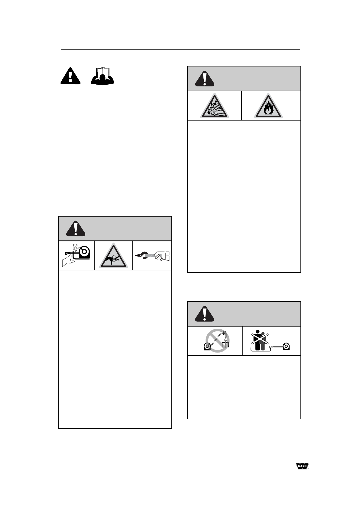
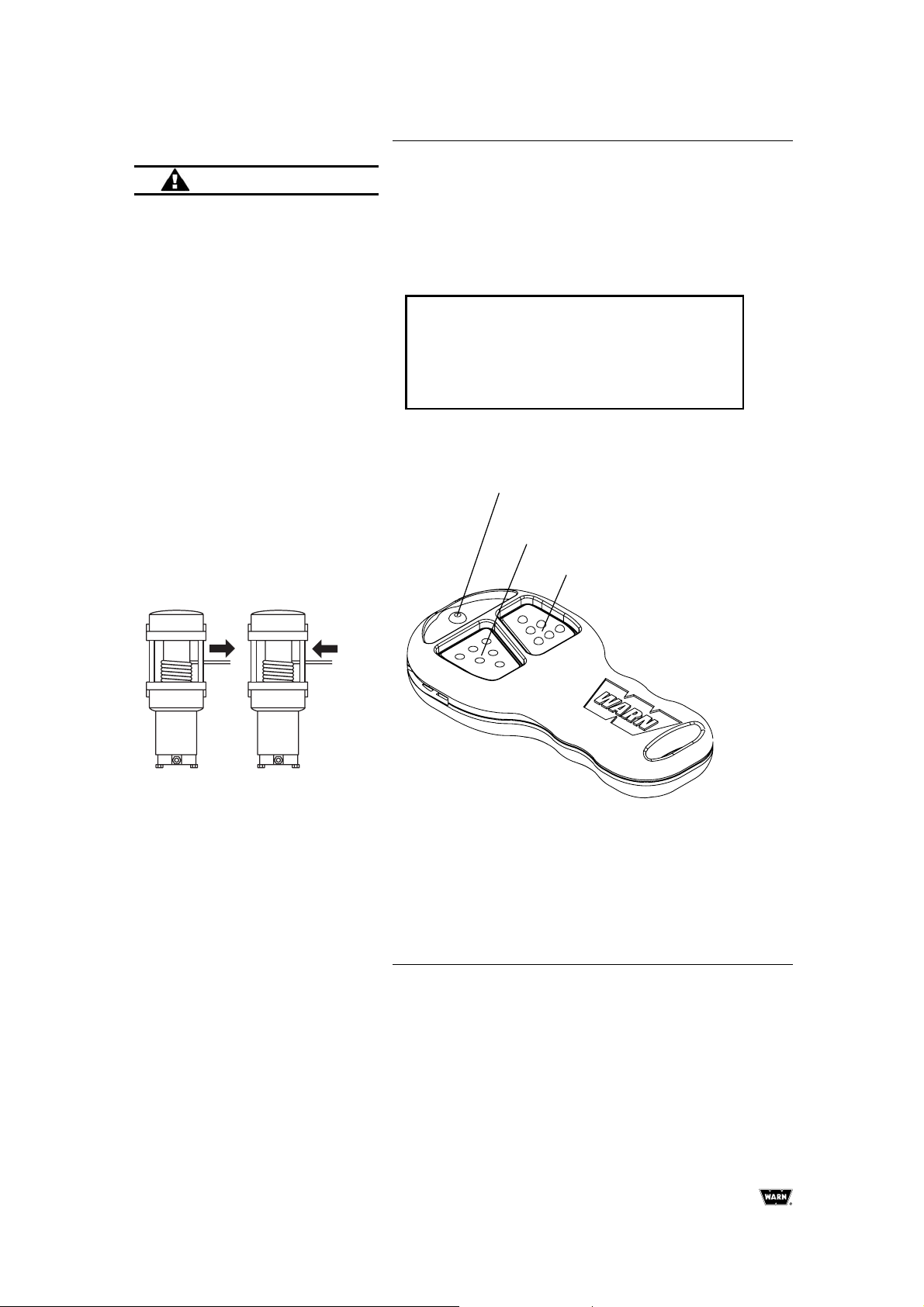
OVERVIEW
The WARN Wireless Control gives you the ability to operate
the winch using a wireless hand held remote. The wireless
control system integrates with the standard handlebar switch
and remote so that the operator may use either the wired or
wireless controls at any time.
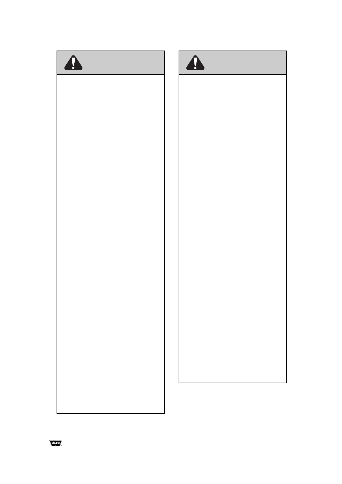
To use the wireless system, the operator first activates the
system by pressing and holding both buttons on the wireless
remote for 3 seconds. This transfers control of the winch to
the wireless control system. The GREEN indicator light on
the handheld remote glows when the system is active and
ready to use.
After 2 minutes of idle time, the wireless system de-activates.
SAFETY
When installing your winch and winch control system, read
and follow all mounting and safety instructions. Always use
caution when working with electricity and remember to verify
that no exposed electrical connections exist before
energizing your winch circuit.
SPECIFICATIONS
Part numbers for complete system:
PN 74500 (wireless control upgrade kit)
PN 74600 (kit supplied with new ATV winch)
Transmission range:
15-27 m (50-90 ft.)
Receiver Operating voltage:
8 to 24 VDC
Receiver Fuse type and current rating:
ATC 7.5 amp
Batteries for hand held remote:
two alkaline, 12 volt, type 23
WIRELESS CONTROL
KIT INCLUDES:
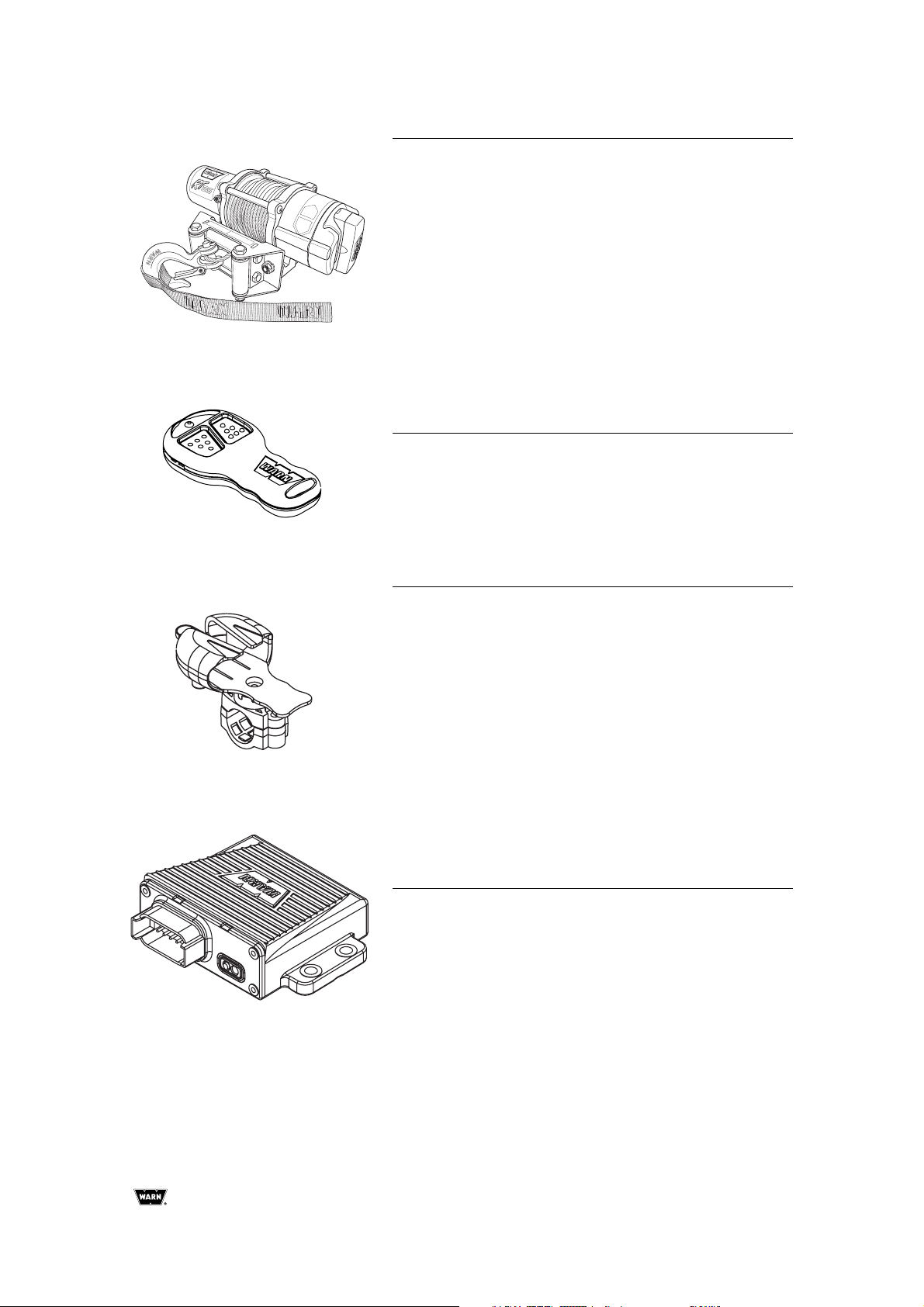
Wireless Receiver (1)
Wireless Transmitter (1)
Wiring Harness (1)
Holster Assembly (1)
Hardware Kit (1)
Page 7
WARN Wireless Control Installation Guide
5
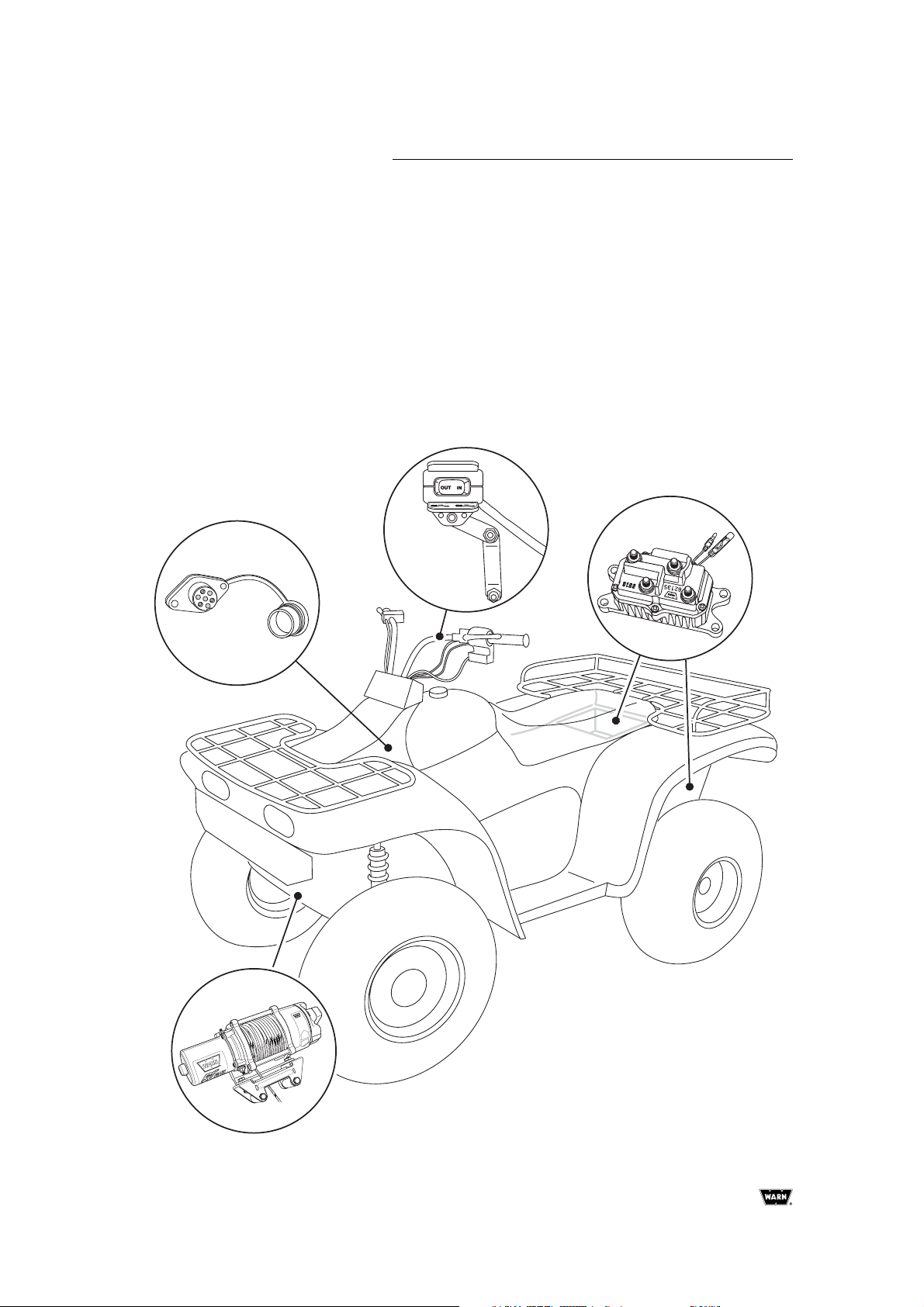
STEP 1: MOUNT ALL WINCH
COMPONENTS
First install the winch and other components including the
contactor, handlebar switch, and socket for wired remote
(optional on some models). Then install the wireless control
system.
Location for these components may differ from the illustration
depending on make and model of the ATV. Read and
understand the instructions to choose the appropriate
mounting locations.
Socket for standard remote
Winch
Electrical contactor
Handlebar mounted
control switch
Page 8
Warn Industries, Inc.
6
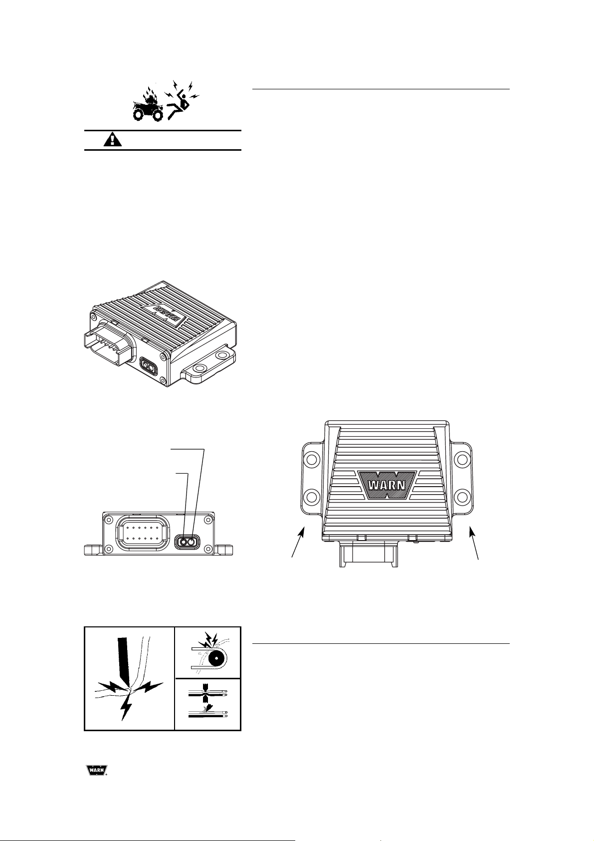
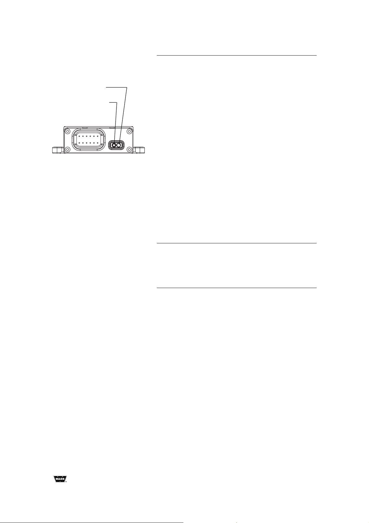
STEP 2: MOUNT THE RECEIVER
What is the receiver?
The receiver is a vital safety component of your wireless
winch system. It disconnects the winch from its power source
when the ATV is not in use. The receiver must be correctly
installed to work properly.
The receiver should be mounted in a location that is as clean
and dry as possible while also allowing access to the
programming button. The mounting location must also
provide clearance for the wire harness to attach to the
receiver.
Best locations for the receiver will vary depending on the
ATV. Typical locations include the inside, top, or side of the
rear storage box or under the seat. The receiver can be
attached to a flat surface or to a frame tube of the ATV.
Mounting Steps:
1. Determine the mounting location.
2. If mounting on a flat surface, mark and drill a minimum of
two (2) mounting holes, one on each side of the receiver.
3. Loosely attach the receiver using 1/4-inch or M6 bolts and
locknuts.
4. If mounting on a frame tube, loosely attach using the wire
ties supplied.
5. Do not tighten fasteners at this time.
Programming LED
Programming button
Minimum of one fastener on each side
WARNING
TO PREVENT SERIOUS INJURY
OR DEATH FROM EXPLOSION:
•
Do not drill into gas tank.
•
Verify the area is clear behind the
mounting location before drilling.
STEP 3: ROUTE THE HARNESS
Locate the BLACK and GREEN wires running from the
contactor to the handlebar switch. Find the bullet connectors
on these wires located near the contactor.
Plan a route for the wire harness between the receiver and
these bullet connectors.
Page 9
WARN Wireless Control Installation Guide
7
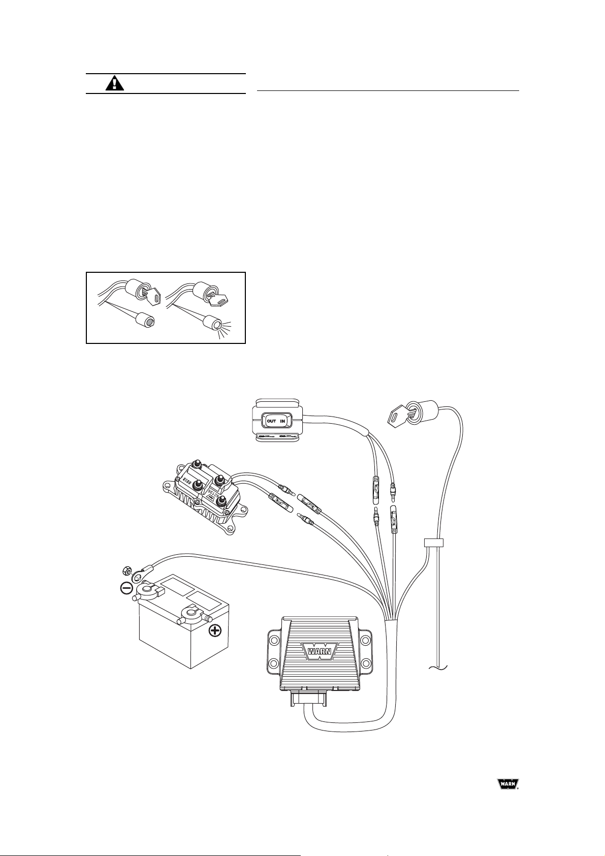
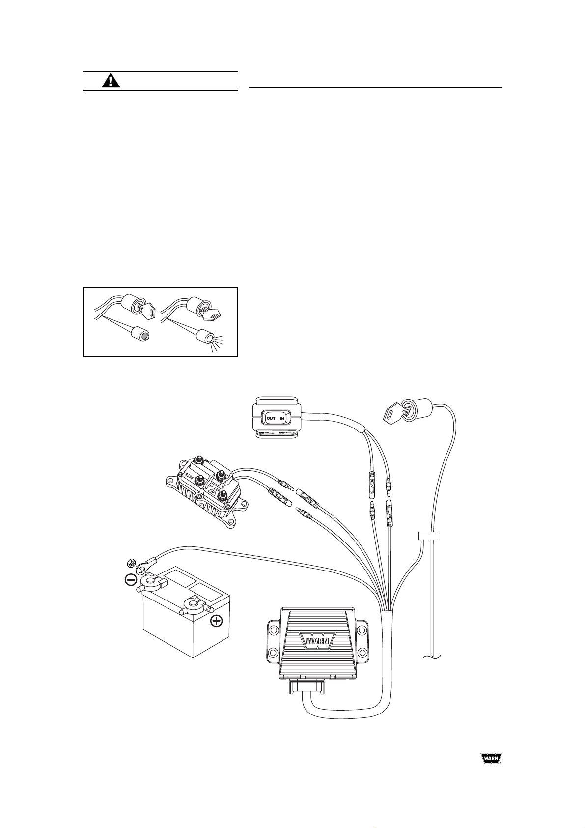
STEP 4: CONNECT THE WIRING
Note: Refer to Figure 1.
1. Pull apart the bullet connectors on the BLACK and
GREEN wires identified in Step 3 above. These will be
located near the contactor
2. Connect the BLACK and GREEN wires to the same color
wires on the wire harness as shown on the wiring diagram.
3. Connect the BLACK ground wire with the ring terminator to
the battery as shown.
4. Using a test light, locate a switched accessory wire
attached to the ATV ignition system. The wire should only
have power when the key is in the "ON" position.
5. Splice the RED wire to the key controlled accessory wire
using the provided wire splice.
6. Connect the other end of the wire harness to the receiver
and tighten the mounting bolts on the receiver.
7. Use tie wraps to secure the wire harness
WARNING
TO PREVENT SERIOUS INJURY
OR DEATH FROM ELECTRICAL
FIRE:
•
Do not route electrical cables
across sharp edges.
•
Do not route electrical cables
through or near moving parts.
•
Do not route electrical cables
through or near any high heat
parts.
•
Avoid pinch and wear/abrasion
points when installing all electrical
cables.
Use a test light to locate a
switched accessory wire.
Figure 1: Wiring Installation Diagram
green
black
black
black
green
red
Page 10
Warn Industries, Inc.
8
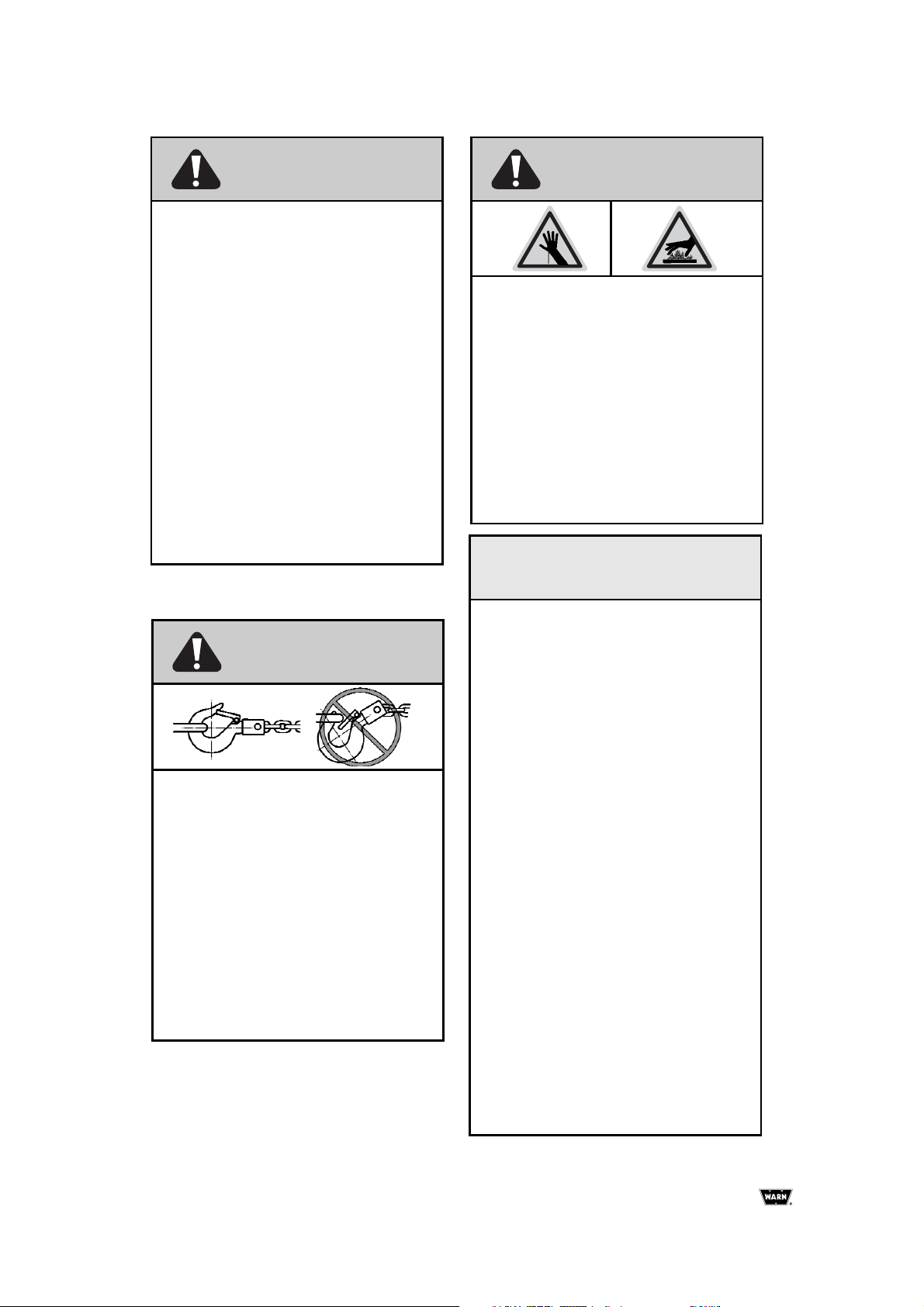
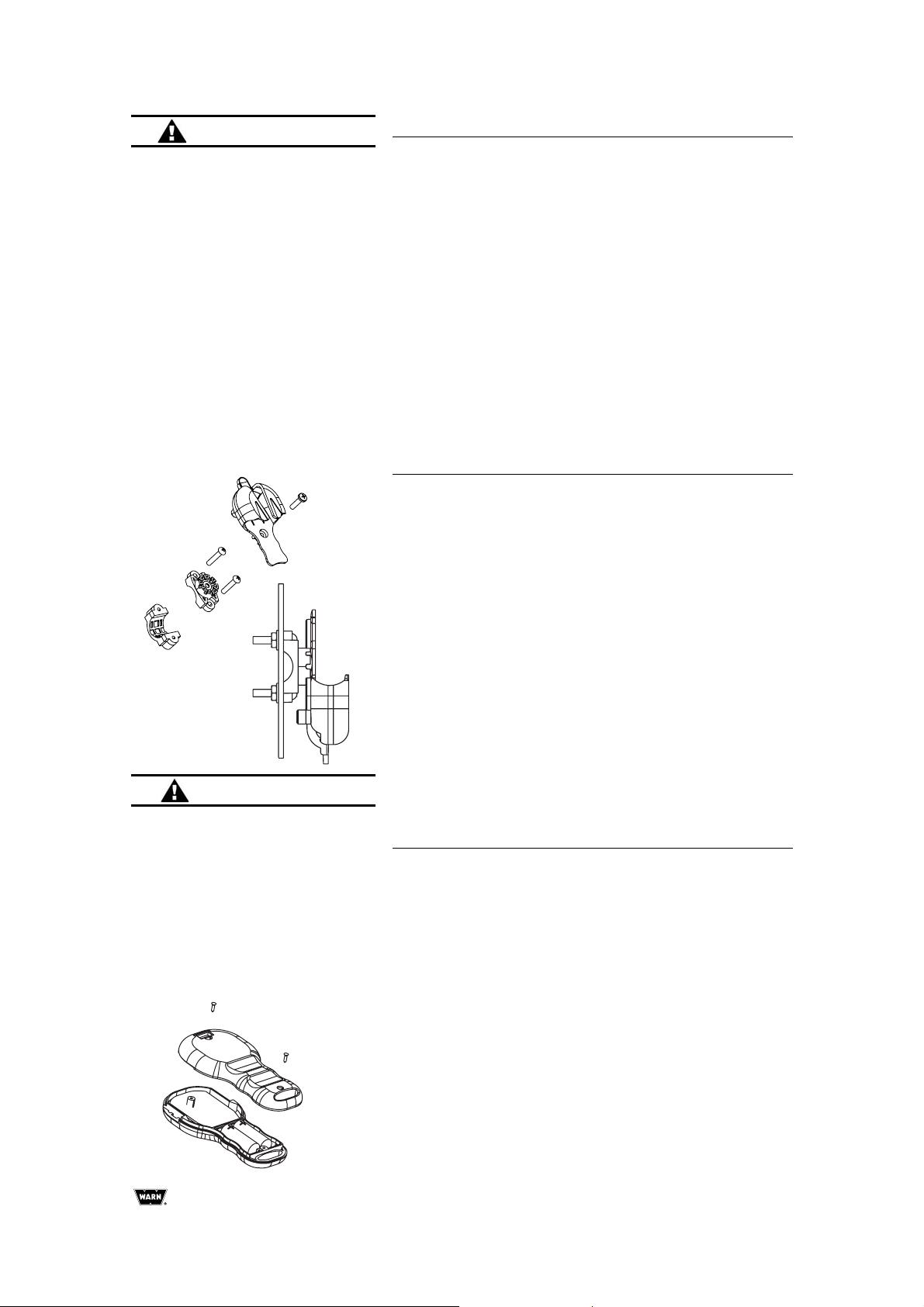
STEP 5: MOUNT THE HOLSTER
For ATV use, the typical location for the holster is on the left
handlebar.
•
The holster clamp must be mounted before assembly
•
Do not tighten over any hoses, cables, or wiring.
•
For ATVs, it is recommended that the holster be clamped
on the left handlebar. The clamp is designed to prevent
rotation. If necessary, a piece of electrical tape around the
handlebar may be used to prevent slipping.
•
For UTVs, the holster may be mounted on the dash or
other convenient surface using two #10 or M5 machine
screws and locknuts.
•
Assemble the holster as shown. Holster may be oriented
in any one of eight positions.
STEP 6: SYSTEM CHECK
1. Insure that wiring to all components is correct and all loose
wires are securely tie wrapped.
2. Insure that there are no exposed terminals or wiring.
Cover any bare terminal with terminal boots, heat shrink
tubing or electrical tape.
3. Turn ATV ignition switch to the ON position.
4. Check winch for proper operation using the handlebar
switch. The wire rope should spool in and out in the
direction indicated on the switch. If winch functions
correctly, proceed to the next step. Otherwise
troubleshoot.
5. Press and hold both buttons on the wireless handheld
remote until the GREEN indicator light comes on. The
wireless system is now active and ready to use.
6. By pressing the buttons on the remote, verify that the
winch powers IN and powers OUT properly.
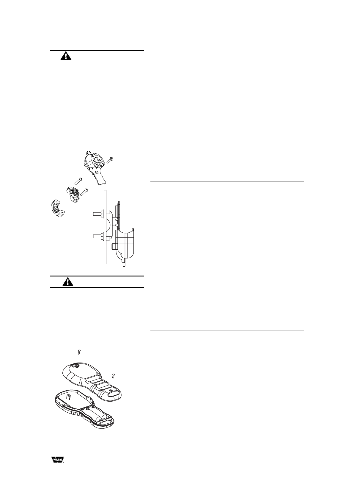
REPLACING BATTERIES
If the indicator light on the handheld remote flashes RED
during winching or the transmission range is reduced, the
batteries are low and should be replaced.
1. Remove the two screws from the handheld remote.
2. Seperate the top and bottom sections of the remote using
a coin or screw driver.
3. Remove the old batteries and dispose in accordance with
local enviromental regulations.
4. Insert new alkaline batteries as shown with the positive
terminals facing the switches. Do not mix old and new
batteries.
5. Join the top and bottom sections making sure that the
rubber seal remains intact.
6. Secure with the two screws.
CAUTION
KNOW YOUR WINCH:
Before doing a system check, take
time to fully understand your winch
and the winching operation by
reviewing the Basic Guide to
Winching Techniques included with
your winch.
WARNING
TO AVOID INJURY AND
PROPERTY DAMAGE:
•
Use caution when moving or
repositioning any vehicle controls
so as to not compromise the safe
operation of the ATV. Select a
mounting position that will provide
clearance for all vehicle controls.
•
Do not attempt to bypass receiver
by connecting switches directly to
contactor.
Page 11
WARN Wireless Control Installation Guide
9
OUT
IN
LED indicator light
Power IN
Power OUT
Press and hold
both buttons for
3 seconds to
activate wireless
system.
TROUBLESHOOTING
If the winch does not power in or out when remote buttons
are pushed:
1. Check that the wireless system has been activated
(GREEN LED on remote is ON).
2. Check all electrical connections. Verify that connections
follow the wiring diagram and instructions.
3. Insure that 10 seconds have passed since the standard
wired control system was last used.
OPERATION
LED Indicator Light
Steady GREEN - system active and ready to use
Steady RED - winch powering in or out
Flashing RED - battery low
1. Activate the system by pressing both buttons
simultaneously and holding for 3 seconds until GREEN
light comes on.
2. Press the power IN or power OUT button to use the winch.
CAUTION
This WARN Wireless Control
System has been designed to
minimize interference from other
sources of radio.
•
Always be aware that obstacles
and other radio transmission
sources may affect performance.
•
Always insure the matching
WARN transmitter is closer to its
receiver than other transmitters in
use during winching.
Page 12
Warn Industries, Inc.
10
Programming LED
Programming button
PROGRAMMING THE RECEIVER
The hand held remote (transmitter) is programmed from the
factory to communicate with your specific receiver. Under
normal circumstances programming will not be necessary.
However, any replacement remote must be programmed to
communicate with your receiver. Use the following
procedure:
1. Insure the system is properly installed and connected.
2. Turn the ATV ignition key to ON.
3. Activate the system by pressing and holding both buttons
until the GREEN LED lights up.
4. Press and hold the receiver programming button for at
least five (5) seconds until the RED LED on the receiver
lights up and stays on.
5. Release the programming button.
6. Press the power IN button on the remote for at least one
(1) second until the RED LED on the receiver turns off.
Programming is now complete.
NOTE: Only one remote can be programmed for each
receiver.
WARRANTY
Please refer to the warranty sheet enclosed with your winch
for details.
REPLACEMENT PART NUMBERS
Ordering information: Parts may be obtained through your
local dealer or distributor.
Part Number Description
PN 74502 Receiver Module
PN 74524 Holster
PN 74525 Harness
PN 74604 Hardware Kit
PN 74520 Replacement transmitter (remote)
The above list represents the most commonly requested
replacement parts. A full listing of replacement and service
parts are available. Check with your WARN authorized dealer
or on the web: www.warn.com
Page 13

Guide d'installation de télécommande sans fil WARN
11
Les directives suivantes comprennent des indications
intitulées AVERTISSEMENT, MISE EN GARDE, AVIS
et REMARQUE. Chacune a un objectif bien précis :
AVERTISSEMENT présente des consignes de sécurité
soulignant un danger potentiel qui, s'il n'est pas évité,
peut entraîner des blessures graves. MISE EN
GARDE comprend des consignes de sécurité signalant
un danger potentiel qui, s'il n'est pas évité, peut
entraîner des blessures légères ou modérées. MISE
EN GARDE sert aussi à signaler une utilisation
dangereuse. MISE EN GARDE et AVERTISSEMENT
identifient un danger, indiquent comment l'éviter et
montrent ses conséquences possibles si on l'ignore.
AVIS présente des consignes visant à éviter les
dommages matériels. REMARQUE donne des
renseignements additionnels qui aident à accomplir
une procédure. TRAVAILLEZ PRUDEMMENT !
AVERTISSEMENT
DANGER DE HAPPEMENT PAR DES
PIÈCES MOBILES
Le non-respect des consignes peut entraîner des
blessures graves ou la mort.
• Toujours garder les mains éloignées du câble,
de la boucle du crochet, du crochet et de
l'ouverture du guide-câble durant l'installation
et l'utilisation du treuil et l'enroulement ou le
déroulement du câble.
• Toujours faire très attention en manipulant le
crochet et le câble pendant les manœuvres de
déroulement.
• Toujours utiliser le cordon du crochet fourni
pour enrouler ou dérouler le câble, durant
l'installation ou l'utilisation.
• Toujours garder l'œil sur le véhicule durant les
opérations de treuillage.
• Toujours porter des gants de cuir épais durant
la manipulation du câble.
RISQUES ASSOCIÉS AUX PRODUITS
CHIMIQUES ET RISQUE D'INCENDIE
Le non-respect des consignes peut entraîner des
blessures graves ou la mort.
Toujours retirer les bijoux et porter des
lunettes de sécurité.
• Ne jamais se pencher au-dessus de la batterie
en procédant aux connexions.
• Avant de percer, toujours s'assurer que la zone
ne contient pas de conduites de carburant, de
réservoir de carburant, de conduites de frein,
de câblage électrique, etc.
• Ne jamais faire passer des câbles électriques :
-Sur des bords tranchants.
-Par des pièces mobiles ou à proximité.
-À proximité de pièces pouvant devenir
chaudes.
• Toujours isoler et protéger tous les fils et
bornes électriques exposés.
• Toujours installer les capuchons de borne de
la manière indiquée dans les instructions
d'installation.
DANGER DE CHUTE OU D'ÉCRASEMENT
Le non-respect des consignes peut entraîner des
blessures graves ou la mort.
• Ne jamais utiliser le treuil pour soulever ou
transporter des personnes.
• Ne jamais utiliser le treuil comme palan ou
pour suspendre une charge.
AVERTISSEMENT
AVERTISSEMENT
MESURES GÉNÉRALES DE SÉCURITÉ
Page 14

Warn Industries, Inc.
12
MISE EN GARDE
DANGER DE HAPPEMENT PAR DES
PIÈCES MOBILES
Le non-respect des instructions peut entraîner
des blessures mineures ou modérées.
• Toujours se familiariser avec le treuil.
Prendre le temps de bien lire le manuel
d'installation et le manuel de base des
techniques de treuillage afin de comprendre
l'appareil et son fonctionnement.
• Les personnes âgées de moins de 16 ans ne
doivent jamais faire fonctionner cet
appareil.
• Ne jamais faire fonctionner l'appareil sous
l'effet de drogues, de l'alcool ou de
médicaments.
• Ne jamais excéder la capacité nominale du
treuil ou du câble d'acier indiquée sur la
fiche technique du produit. Un câblage
double avec poulie ouvrante permet de
réduire la charge subie par le treuil.
• Ne jamais se servir du treuil ou du câble
pour faire du remorquage.
• Toujours choisir une surface de montage
suffisamment résistante pour supporter la
capacité de traction maximale du treuil.
• Toujours utiliser du matériel de montage,
des composants et des accessoires
homologués par le fabricant.
• Toujours utiliser un matériel de montage de
catégorie 5 ou supérieure.
• Ne jamais souder les boulons de montage.
• Toujours faire attention quand on utilise des
boulons plus longs que ceux fournis par le
fabricant. Des boulons trop longs peuvent
endommager la base ou empêcher le treuil
d'être monté de manière sûre.
• Toujours monter le treuil et fixer le crochet
à la boucle d'extrémité du câble avant de
raccorder le câblage électrique.
• Toujours positionner le guide-câble avec
l'étiquette d'AVERTISSEMENT sur le dessus.
• Toujours enrouler le câble sur le tambour
dans le sens spécifié par l'étiquette
d'avertissement apposée sur le treuil ou la
documentation du treuil. Cela est nécessaire
pour que le frein automatique fonctionne
correctement.
• Toujours étirer le câble au préalable et
l'enrouler sous charge avant de l'utiliser. Un
câble enroulé de manière serrée réduit le
risque qu'il coince et soit endommagé.
MISE EN GARDE
DANGER DE HAPPEMENT PAR DES
PIÈCES MOBILES
Le non-respect des instructions peut entraîner
des blessures mineures ou modérées.
• Toujours inspecter le câble, le crochet et les
élingues avant de faire fonctionner le treuil.
Tous les composants endommagés doivent
être remplacés avant d'utiliser le produit.
Protéger toutes les pièces contre le risque
de dommages.
• Ne jamais laisser la télécommande
branchée sur le treuil durant la mise en
roue libre, le câblage ou quand le treuil
n'est pas utilisé.
• Ne jamais accrocher le câble à lui-même.
Cela l'endommagerait.
• Toujours utiliser une chaîne ou un câble à
nœud coulant, ou une protection de tronc
d'arbre sur le point d'ancrage.
• Toujours s'assurer que tous les obstacles
potentiels sont écartés.
• Toujours prendre le temps d'utiliser les
techniques de câblage appropriées avant de
faire fonctionner le treuil.
• Toujours s'assurer que le point d'ancrage
choisi peut supporter la charge et que la
sangle ou la chaîne ne glisse pas.
• Ne jamais essayer d'embrayer ou de
débrayer si le treuil est sous charge, si le
câble est en tension ou si le tambour est en
train de tourner.
• Ne jamais utiliser le treuil avec moins de 5
spires de câble enroulées autour du
tambour. Le câble pourrait se dérouler du
tambour.
• Ne jamais toucher le câble ou le crochet
lorsque le câble est tendu ou sous charge.
• Ne jamais toucher le câble ou le crochet
lorsqu'une autre personne manipule
l'interrupteur de commande ou durant le
fonctionnement du treuil.
• Toujours se tenir à l'écart du câble et de la
charge et ne jamais laisser personne
s'approcher durant l'utilisation.
• Toujours être conscient de la stabilité du
véhicule et de la charge durant l'utilisation.
Alerter toutes les personnes alentour en
cas d'instabilité.
• Ne jamais se servir du treuil pour maintenir
une charge.
Page 15

Guide d'installation de télécommande sans fil WARN
13
MISE EN GARDEMISE EN GARDE
AVIS
MISE EN GARDE
DANGER DE HAPPEMENT PAR DES
PIÈCES MOBILES
Le non-respect des instructions peut entraîner
des blessures mineures ou modérées.
• Toujours garder le fil de la télécommande à
l'écart du tambour, du câble et du câblage.
S'assurer qu'il n'y a pas de fissures, de
points de pincement, de fils effilochés ou de
connexions desserrées. Remplacer la
télécommande en cas de dommages.
• Si l'on manie la télécommande de l'intérieur
d'un véhicule, toujours faire passer la
télécommande par la fenêtre pour éviter de
pincer le fil.
• Ne jamais laisser la télécommande dans un
endroit où elle peut être activée durant la
mise en roue libre, le câblage ou quand le
treuil n'est pas utilisé.
RISQUE DE COUPURE ET DE BRÛLURE
Le non-respect des instructions peut entraîner
des blessures mineures ou modérées.
Pour éviter de se blesser les mains et les doigts :
• Toujours porter des gants de cuir résistants
durant la manipulation du câble.
• Ne jamais laisser le câble glisser dans les
mains.
• Toujours penser aux surfaces chaudes au
niveau du moteur du treuil, du tambour ou
du câble durant ou après l'utilisation du
treuil.
DANGER DE HAPPEMENT PAR DES
PIÈCES MOBILES
Le non-respect des instructions peut entraîner
des blessures mineures ou modérées.
• Toujours utiliser un crochet avec loquet.
• Toujours s'assurer que le loquet du crochet
est fermé et qu'il ne supporte aucune
charge.
• Ne jamais appliquer la charge sur
l'extrémité ou le loquet du crochet. Appliquer
la charge uniquement au centre du crochet.
• Ne jamais utiliser un crochet dont
l'ouverture de la gorge a augmenté ou dont
l'extrémité est courbée ou tordue.
ÉVITER D'ENDOMMAGER LE TREUIL ET
L'ÉQUIPEMENT
• Toujours éviter de tirer sur le côté, ce qui a
pour effet d'empiler le câble sur l'une des
extrémités du tambour. Cela peut
endommager le câble ou le treuil.
• Toujours s'assurer d'avoir complètement
embrayé ou complètement débrayé.
• Ne jamais se servir du treuil pour remorquer
d'autres véhicules ou objets. Les charges de
choc peuvent momentanément dépasser de
loin la capacité du câble et du treuil.
• Toujours éviter de dérouler le câble sur de
grandes distances. Cela pourrait surchauffer
et user le moteur du treuil et le frein.
• Toujours faire attention à ne pas
endommager le cadre si l'on décide d'arrimer
le véhicule pour pouvoir travailler avec le
treuil.
• Ne jamais " secouer " le câble sous charge.
Les charges de choc peuvent
momentanément dépasser de loin la capacité
du câble et du treuil.
• Ne jamais se servir du treuil pour maintenir
une charge pendant le transport.
• Ne jamais submerger le treuil dans l'eau.
• Toujours ranger la télécommande dans un
endroit sûr, propre et sec.
• Toujours utiliser une ligne double ou choisir
un point d'ancrage distant pour le câblage.
Cela optimise la puissance de traction et
évite de surcharger le treuil.
Page 16

Warn Industries, Inc.
14
PRÉSENTATION
La télécommande sans fil WARN permet de faire fonctionner
le treuil à l'aide d'une télécommande de poche sans fil. Le
système de télécommande sans fil s'intègre à l'interrupteur
sur guidon avec télécommande standard de sorte que
l'opérateur peut utiliser en tout temps la télécommande avec
ou sans fil.
Pour utiliser le système sans fil, l'opérateur active d'abord le
système en maintenant enfoncés les deux boutons de la
télécommande sans fil pendant 3 secondes. Cela transfère le
contrôle du treuil au système de télécommande sans fil. Le
voyant VERT de la télécommande de poche s'allume lorsque
le système est activé et prêt à être utilisé.
Après 2 minutes de temps mort, le système sans fil se
désactive.
SÉCURITÉ
Lire et suivre les instructions de montage et de sécurité lors
de l’installation du système de treuil et de commande du
treuil. Toujours faire attention lorsqu’on travaille avec
l’électricité et ne pas oublier de s’assurer qu’aucune
connexion électrique n’est exposée avant de mettre le circuit
du treuil sous tension.
CARACTÉRISTIQUES
Numéros de référence du système complet :
Réf. 74500 (kit de mise à jour de télécommande sans fil)
Réf. 74600 (kit fourni avec un treuil neuf de quad)
Portée de transmission :
15-27 m
Tension de fonctionnement du récepteur :
8 à 24 V c.c.
Type et courant nominal du fusible de récepteur :
ATC - 7,5 A
Piles pour télécommande de poche :
deux piles alcalines de 12 volts, type 23
télécommande sans fil
Le kit comprend :
Récepteur sans fil (1)
Émetteur sans fil (1)
Faisceau de câbles (1)
Étui (1)
Kit de matériel (1)
Page 17

Guide d'installation de télécommande sans fil WARN
15
PREMIÈRE ÉTAPE : MONTAGE DE
TOUS LES ÉLÉMENTS DU TREUIL
Installer d'abord le treuil et les autres éléments y compris le
contacteur, l'interrupteur sur guidon et la douille de la
télécommande à fil (facultatif sur certains modèles). Installer
ensuite le système de télécommande sans fil.
L'emplacement de ces éléments peut différer de celui de
l'illustration selon la marque et le modèle du quad. Prendre
soin de bien lire et comprendre les instructions afin de choisir
les emplacements de montage appropriés.
Douille de télécommande
standard
Treuil
Contacteur électrique
Interrupteur de commande installé
sur le guidon
Page 18

Warn Industries, Inc.
16
ÉTAPE 2 : MONTAGE DU
RÉCEPTEUR
Qu'est-ce qu'un récepteur?
Le récepteur est un élément de sécurité vital de votre
système de treuil sans fil. Il déconnecte le treuil de sa source
d’alimentation lorsque le quad n'est pas utilisé. Le récepteur
doit être correctement installé pour bien fonctionner.
Il doit être monté dans un endroit aussi propre et sec que
possible tout en permettant d'accéder au bouton de
programmation. D'autre part, l'emplacement de montage doit
assurer un dégagement suffisant pour fixer le faisceau de fils
au récepteur.
L’emplacement idéal pour le récepteur variera selon le quad.
L’installation se fait généralement à l’intérieur, sur le dessus
ou le côté de la boîte de rangement arrière ou sous le siège.
Le récepteur peut être fixé à une surface plane ou à un tube
du cadre du quad.
Étapes de montage :
1. Déterminer l'emplacement de montage.
2. Pour le montage sur une surface plane, marquer et percer
deux (2) trous de montage au minimum, un de chaque
côté du récepteur.
3. Fixer sans serrer le récepteur à l'aide de boulons de 1/4
po ou M6 et d'écrous de blocage.
4. Pour le montage sur un tube du cadre, le fixer à l'aide des
liens métalliques fournis.
5. Ne pas serrer les fixations pour l'instant.
DEL de programmation
Bouton de programmation
Une attache minimum de chaque côté
AVERTISSEMENT
POUR ÉVITER LES RISQUES DE
BLESSURES GRAVES OU DE
MORT SUITE À UNE EXPLOSION :
•
Ne pas percer le réservoir à
essence.
•
S’assurer qu’aucun objet ne se
trouve derrière l’emplacement de
montage avant de percer.
ÉTAPE 3 : POSE DU HARNAIS
Repérer les fils NOIR et VERT reliant le contacteur à
l'interrupteur sur guidon. Trouver les connecteurs coniques
sur ces fils situés près du contacteur.
Prévoir de faire passer le faisceau de fils entre le récepteur
et ces connecteurs coniques.
Page 19

Guide d'installation de télécommande sans fil WARN
17
ÉTAPE 4 : CONNEXION DU
CÂBLAGE
Remarque : Voir la Figure 1.
1. Séparer les connecteurs coniques des fils NOIR et VERT
identifiés à l'étape 3 ci-dessus. Ils devraient se trouver
près du contacteur.
2. Brancher les fils NOIR et VERT aux fils de même couleur
du faisceau de fils tel qu'indiqué sur le schéma de
câblage.
3. Brancher le fil de masse NOIR à borne à anneau de la
batterie, tel qu'indiqué.
4. Repérer, à l’aide d’une lampe témoin, un fil commuté relié
au système d'allumage du quad. Le fil ne doit être sous
tension que lorsque la clé est en position « ON »
(marche).
5. Épisser le fil ROUGE avec le fil électrique contrôlé par
contact (utiliser l'épissure fournie).
6. Connecter l'autre extrémité du faisceau de fils au
récepteur et serrer les boulons de fixation sur le récepteur.
7. Fixer les fils au moyen d'attaches.
AVERTISSEMENT
POUR ÉVITER LES RISQUES DE
BLESSURES GRAVES OU
MORTELLES SUITE À UN FEU
ÉLECTRIQUE :
•
Ne pas faire passer les câbles
électriques sur des bords
tranchants.
•
Ne pas faire passer les câbles
électriques à travers des pièces
mobiles ou à proximité.
•
Ne pas faire passer les câbles
électriques à travers des pièces
très chaudes ou à proximité.
•
Éviter les points de pincement et
d'usure/abrasion lors de
l'installation des câbles
électriques.
Utiliser une lampe témoin pour
trouver un fil commuté.
Figure 1 : Schéma de câblage
vert
noir
noir
noir
vert
rouge
Page 20

Warn Industries, Inc.
18
ÉTAPE 5 : MONTAGE DE L'ÉTUI
Sur un quad, l'étui est généralement placé sur la poignée
gauche.
•
Le collier de l'étui doit être monté avant l'assemblage.
•
Ne pas serrer sur des tuyaux, des câbles ou des fils.
•
Il est recommandé d’installer l’étui sur la poignée gauche
du quad. Le collier est conçu de façon à empêcher la
rotation. Enrouler au besoin un bout de ruban isolant
autour de la poignée pour empêcher le collier de glisser.
•
Sur un véhicule utilitaire, placer l'étui sur le tableau de
bord ou une autre surface pratique à l'aide de deux vis à
métaux n° 10 ou M5 avec écrous de blocage.
•
Assembler l'étui comme indiqué. On peut orienter l'étui
dans huit positions différentes.
ÉTAPE 6 : VÉRIFICATIONS DU
SYSTÈME
1. S’assurer que le câblage de tous les éléments est correct
et que tous les fils desserrés sont bien fixés à l'aide
d'attaches.
2. S’assurer qu'il n'y a pas de bornes ou de câblage exposé.
Couvrir les bornes exposées à l’aide de capuchons, de
gaines thermorétrécissables ou de ruban isolant.
3. Mettre le contacteur d'allumage du quad en position ON.
4. Vérifier que le treuil fonctionne correctement au moyen de
l'interrupteur sur guidon. Le câble d'acier doit se dérouler
et s’enrouler dans le sens indiqué sur l’interrupteur. Si le
treuil fonctionne correctement, passer au point suivant.
Sinon, effectuer un dépannage.
5. Maintenir enfoncés les deux boutons de la télécommande
de poche sans fil jusqu'à ce que le voyant VERT s'allume.
Le système sans fil est maintenant activé et prêt à
l'emploi.
6. Tout en appuyant sur les boutons de la télécommande,
s’assurer que le treuil enroule et déroule le câble
correctement.
REMPLACEMENT DES PILES
Si la lumière du voyant de la télécommande de poche
clignote en ROUGE durant le treuillage ou que la portée de
transmission semble réduite, cela indique que les piles sont
faibles et qu'elles doivent être remplacées.
1. Retirer les deux vis de la télécommande de poche.
2. Séparer les parties supérieure et inférieure de la
télécommande à l'aide d'une pièce de monnaie ou d'un
tournevis.
3. Retirer les vieilles piles et s’en débarrasser conformément
à la réglementation en vigueur.
4. Insérer des piles alcalines neuves tel qu'indiqué, les
bornes positives étant orientées vers les commutateurs.
Ne pas mélanger des piles usagées et des piles neuves.
5. Joindre les parties supérieure et inférieure en s’assurant
que le joint en caoutchouc reste intact.
6. Fixer le tout à l'aide des deux vis.
MISE EN GARDE
SE FAMILIARISER AVEC LE
TREUIL :
Avant de procéder à une vérification
du système, prendre le temps de
bien se familiariser avec le treuil et
son fonctionnement en examinant le
Manuel de base des techniques de
treuillage inclus avec votre treuil.
AVERTISSEMENT
POUR ÉVITER LES RISQUES DE
BLESSURES ET DE DOMMAGES
MATÉRIELS :
•
Faire attention pour déplacer ou
repositionner les commandes du
véhicule afin de ne pas créer de
risques durant le fonctionnement
du quad. Sélectionner un
emplacement de montage
permettant de dégager toutes les
commandes du véhicule.
•
Ne pas essayer de contourner le
récepteur en connectant les
commutateurs directement au
contacteur.
Page 21

Guide d'installation de télécommande sans fil WARN
19
SORTIE
ENTRÉE
Voyant à DEL
Enrouler
Dérouler
Maintenir enfoncés
les deux boutons
pendant 3
secondes pour
activer le système
sans fil.
DÉPANNAGE
Si le treuil n'enroule ou ne déroule pas le câble lorsque les
boutons de la télécommande sont enfoncés :
1. S'assurer que le système sans fil a été activé (la DEL
VERTE de la télécommande est allumée).
2. Vérifiez les raccordements électriques. Vérifier que les
connexions respectent le schéma de câblage et le mode
d'emploi.
3. Attendre que 10 secondes se soient écoulées depuis la
dernière utilisation du système de télécommande avec fil
standard.
FONCTIONNEMENT
1. Activer le système en appuyant sur les deux boutons
simultanément et en les maintenant enfoncés pendant 3
secondes jusqu'à ce que le voyant VERT s'allume.
2. Appuyer sur le bouton d'enroulement (IN) ou de
déroulement (OUT) pour utiliser le treuil.
Voyant à DEL
VERT continu - Le système est activé et prêt à l'emploi
ROUGE continu - Le treuil enroule et déroule le câble
ROUGE clignotant - Piles faibles
ATTENTION
Le système de télécommande
sans fil WARN a été conçu de
façon à minimiser les parasites
provenant d'autres sources radio.
• Toujours garder à l'esprit que les
obstacles et d'autres sources de
transmission radio peuvent
détériorer les performances.
• Toujours s'assurer que l'émetteur
WARN apparié est plus proche de
son récepteur que d'autres
émetteurs en utilisation durant le
treuillage.
Page 22

Warn Industries, Inc.
20
PROGRAMMATION DU RÉCEPTEUR
La télécommande de poche (émetteur) est programmée en
usine de façon à communiquer avec votre récepteur. Il n'est
pas nécessaire de la programmer, en temps normal.
Toutefois, il faut programmer une télécommande de
remplacement pour qu'elle puisse communiquer avec le
récepteur. Appliquer la procédure suivante :
1. S’assurer que le système est installé et connecté
correctement.
2. Mettre le contacteur à clé du quad sur « ON »(marche).
3. Activer le système en maintenant enfoncés les deux
boutons pendant ce que la DEL VERTE s'allume.
4. Maintenir enfoncé le bouton de programmation du
récepteur pendant au moins cinq (5) secondes jusqu'à ce
que la DEL rouge du récepteur s'allume et le demeure.
5. Relâcher le bouton de programmation.
6. Appuyer sur le bouton d'enroulement (IN) de la
télécommande pendant au moins une (1) seconde jusqu'à
ce que la DEL rouge du récepteur s'éteigne. La
programmation est à présent achevée.
REMARQUE : On ne peut programmer qu'une seule
télécommande par récepteur.
GARANTIE
Pour plus de précisions, consulter la feuille de garantie qui
accompagne votre treuil.
RÉFÉRENCES DES PIÈCES DE
RECHANGE
Pour passer une commande : Les pièces de rechange sont
disponibles auprès du concessionnaire ou du distributeur
régional.
Référence Description
Réf. 74502 Module de récepteur
Réf. 74524 Étui
Réf. 74525 Faisceau de fils
Réf. 74604 Kit de matériel
Réf. 74520 Émetteur de remplacement
(télécommande)
La liste ci-dessus représente les pièces de rechange les plus
fréquemment demandées. Une liste complète des pièces de
rechange est disponible. Consulter votre concessionnaire
agréé WARN ou bien notre site Web : www.warn.com
DEL de programmation
Bouton de programmation
Page 23

Installationsanleitung: WARN Drahtlose Fernsteuerung
21
ACHTUNG
GEFAHR DURCH BEWEGLICHE TEILE
Die Nichtbeachtung dieser Anweisungen kann zu
schweren oder tödlichen Verletzungen führen.
So lassen sich Verletzungen an den Händen und
Fingern vermeiden:
• Kontakt mit dem Seil, der Öse, dem Haken
und der Seilführung während der Installation,
des Betriebs und beim Ab- und Aufspulen
vermeiden.
• Vorsicht beim Umgang mit Haken und Seil
während des Spulvorgangs!
• Beim Auf- und Abspulen, während der
Installation und während des Betriebs immer
den mitgelieferten Hakengurt verwenden.
• Beim Windenbetrieb muss der Blickkontakt mit
dem Fahrzeug stets gegeben sein.
• Bei der Handhabung des Seils stets schwere
Lederhandschuhe tragen.
ACHTUNG
CHEMISCHE UND BRANDGEFAHR
Die Nichtbeachtung dieser Anweisungen kann zu
schweren oder tödlichen Verletzungen führen.
• Schmuckstücke stets entfernen und
Augenschutz tragen.
• Beim Anschluss der Kabel nicht über die
Batterie lehnen.
• Immer sicherstellen, dass sich in dem Bereich,
in dem gebohrt werden soll, keine
Kraftstoffleitungen, Kraftstofftanks,
Bremsleitungen, elektrischen Kabel usw.
befinden.
• Elektrische Kabel niemals
- über scharfe Kanten hinweg verlegen.
- durch oder in der Nähe von beweglichen
Teile verlegen.
- in der Nähe von Teilen verlegen, die
heiß werden können.
• Frei liegende Drähte und elektrische
Anschlüsse sind immer zu isolieren und zu
schützen.
• Schutzmanschetten sind immer gemäß den
Installationsanweisungen anzubringen.
ACHTUNG
STURZ- ODER QUETSCHGEFAHR
Die Nichtbeachtung dieser Anweisungen kann zu
schweren oder tödlichen Verletzungen führen.
• Nicht als Hebevorrichtung oder zum Aufhängen
einer Last verwenden.
• Nicht als Lift oder zur Beförderung von
Personen verwenden.
In diesem Handbuch befinden sich WARNHINWEISE,
VORSICHTSMASSNAHMEN, WICHTIGE
ANMERKUNGEN und HINWEISE. Jede Textart hat
einen bestimmten Zweck. WARNHINWEISE sind
Sicherheitshinweise, die auf eine möglicherweise
gefährliche Situation hinweisen, die zu schweren
Verletzungen führen kann, wenn sie nicht vermieden
wird. VORSICHTSMASSNAHMEN sind
Sicherheitshinweise, die auf eine möglicherweise
gefährliche Situation hinweisen, die zu leichten oder
mäßigen Verletzungen führen kann, wenn sie nicht
vermieden wird. Eine VORSICHTSMASSNAHME
kann auch auf unsichere Praktiken hinweisen.
VORSICHTSMASSNAHMEN und WARNHINWEISE
kennzeichnen die Gefahr, weisen auf Möglichkeiten
zur Vermeidung der Gefahr hin und geben Aufschluss
über die möglichen Folgen, wenn diese Gefahr nicht
vermieden wird. Das Signalwort WICHTIG weist auf
Anmerkungen mit Vorgehensweisen zur Vermeidung
von Sachschäden hin. HINWEISE liefern zusätzliche
Informationen, die Ihnen helfen, ein bestimmtes
Verfahren durchzuführen. BITTE UNBEDINGT ALLE
SICHERHEITSMASSNAHMEN BEACHTEN!
ALLGEMEINE SICHERHEITSHINWEISE
Page 24

Warn Industries, Inc.
22
VORSICHT
GEFAHR DURCH BEWEGLICHE TEILE
Die Nichtbeachtung dieser Anweisungen kann zu
leichten oder mäßigen Verletzungen führen.
Allgemeine Sicherheitsmaßnahmen:
• Sie sollten stets mit dem Betrieb und allen
Komponenten der Winde vertraut sein.
Installationsanleitung der Winde sowie die
Richtlinien zur Windentechnik vollständig
lesen.
• Nur Personen, die mindestens 16 Jahre alt
sind, dürfen diese Winde in Betrieb nehmen.
• Winde niemals unter Alkohol-, Drogen- oder
Medikamenteneinfluss in Betrieb nehmen.
• Die auf dem Datenblatt angegebene Zuglast
der Winde bzw. des Seils darf niemals
überschritten werden. Zur Reduzierung der
Last sind eine Umlenkrolle und ein zweifach
geschertes Seil erforderlich.
• Weder die Winde noch das Seil zum Ziehen
von Lasten verwenden.
Sicherheitsmaßnahmen bei der Installation:
• Die Befestigungsstelle sollte immer fest genug
sein, um der maximalen Nennleistung der
Winde standhalten zu können.
• Nur vom Hersteller zugelassene
Befestigungsteile, Komponenten und
Zubehörteile verwenden.
• Die Metallteile müssen stets mindestens
Grade 5 entsprechen.
• Keine Schweißbolzen verwenden.
• Vorsicht bei der Verwendung von Bolzen, die
länger als die im Lieferumfang enthaltenen
Bolzen sind. Zu lange Bolzen können den
Sockel beschädigen und/oder eine sichere
Befestigung der Winde verhindern.
• Vor Anschluss der Elektrik ist die Winde immer
fest zu installieren und der Haken an der
Endschlaufe des Seils zu befestigen.
• Seilführung immer so positionieren, dass das
Warnetikett nach oben zeigt.
• Seil immer in der auf dem Warnetikett der
Winde bzw. in den Unterlagen angegebenen
Richtung auf die Trommel spulen. Diese
Maßnahme ist für die ordnungsgemäße
Funktion der Automatikbremse unerlässlich.
• Seil vor Inbetriebnahme immer erst dehnen
und unter Last neu aufspulen. Ein fest
aufgespultes Seil reduziert das Risiko, dass
sich die Seillagen lockern und hängen bleiben
oder Schäden verursachen.
VORSICHT
GEFAHR DURCH BEWEGLICHE TEILE
Die Nichtbeachtung dieser Anweisungen kann zu
leichten oder mäßigen Verletzungen führen.
Sicherheitsmaßnahmen beim Windenbetrieb:
• Seil, Haken und Schlingen müssen vor
Inbetriebnahme der Winde geprüft werden.
Beschädigte Komponenten sind vor
Inbetriebnahme auszutauschen. Alle
Einzelteile sind vor Schäden zu schützen.
• Die verkabelte Fernsteuerung darf Freilauf,
Abspannen oder bei Nichtgebrauch der Winde
nicht an der Winde angeschlossen bleiben.
• Seil niemals am Seil einhaken. Dadurch wird
das Seil beschädigt.
• Stets eine Kette, ein Seil oder eine sonstige
Schutzvorrichtung (z.B. für Bäume) mit dem
Anker verwenden.
• Gegenstände oder Hindernisse, die einen
sicheren Betrieb der Winde beeinträchtigen
könnten, sind zu entfernen.
• Vorsicht beim Abspannen in Vorbereitung des
Windenvorgangs!
• Sicherstellen, dass der gewählte Anker der
Last standhalten kann und dass weder der
Riemen noch die Kette verrutschen können.
• Kupplung bei belasteter Winde, gespanntem
Seil oder sich bewegender Seiltrommel nicht
ein- oder ausrasten lassen.
• Der Betrieb der Winde mit weniger als 5
Seilwicklungen um die Trommel wird nicht
empfohlen. Das Seil könnte sich von der
Trommel lösen.
• Niemals Seil oder Haken berühren, wenn
diese unter Spannung stehen.
• Während des Windenbetriebs - oder wenn
jemand anderes die Steuerung der Winde
übernommen hat - weder Seil noch Haken
berühren.
• Abstand zum Seil und der Last einhalten und
andere Personen während des
Windenbetriebs fern halten.
• Das Betriebspersonal muss sich der Stabilität
von Fahrzeug und Last während des Betriebs
der Winde bewusst sein. In der Nähe
befindliche Personen müssen über instabile
Zustände informiert werden.
• Winde nicht zur Sicherung der Last
verwenden.
Page 25

Installationsanleitung: WARN Drahtlose Fernsteuerung
23
VORSICHTVORSICHT
HINWEIS
VORSICHT
GEFAHR DURCH BEWEGLICHE TEILE
Die Nichtbeachtung dieser Anweisungen kann zu
leichten oder mäßigen Verletzungen führen.
• Fernsteuerungskabel immer von der Trommel,
dem Seil und beim Abspannen fern halten. Auf
rissige, geknickte oder ausgefranste Drähte
oder lockere Anschlüsse achten. Beschädigte
Fernsteuerungen austauschen.
• Bei Verwendung der verkabelten
Fernsteuerung im Fahrzeug die Fernsteuerung
immer durch das Fenster reichen, um ein
Quetschen des Kabels in der Tür zu
vermeiden.
• Fernsteuerung beim Freilauf, Abspannen oder
bei Nichtgebrauch der Winde entfernen, damit
sie nicht aktiviert werden kann.
SCHNITTVERLETZUNGS- UND
VERBRENNUNGSGEFAHR
Die Nichtbeachtung dieser Anweisungen kann zu
leichten oder mäßigen Verletzungen führen.
• So lassen sich Verletzungen an den Händen und
Fingern vermeiden:
• Bei der Handhabung des Seils stets schwere
Lederhandschuhe tragen.
• Seil nie durch die Hände gleiten lassen.
• Während des Betriebs und nach Verwendung
der Winde immer auf möglicherweise heiße
Flächen in der Nähe des Motors, der Trommel
oder des Seils achten.
GEFAHR DURCH BEWEGLICHE TEILE
Die Nichtbeachtung dieser Anweisungen kann zu
leichten bis mäßigen Verletzungen führen.
• Immer Haken und Riegel verwenden.
• Immer sicherstellen, dass der Riegel
geschlossen ist und keine Last trägt.
• Hakenspitze oder Riegel nicht belasten. Nur
die Hakenmitte belasten.
• Verworfene Haken bzw. Haken mit einer
verbreiterten Durchlassöffnung nicht
verwenden.
SO LASSEN SICH SCHÄDEN AN DER WINDE
UND AN DEN GERÄTEN VERMEIDEN:
Das Einziehen des Seils von der Seite ist zu
vermeiden, da sich das Seil an einem Ende der
Trommel ansammeln kann. Bei Nichtbeachtung
dieser Anweisung können Schäden am Seil oder
der Winde entstehen.
• Immer darauf achten, dass die Kupplung
vollkommen ein- oder ausgerastet ist.
• Winde niemals zum Schleppen anderer Fahrzeuge
oder Objekte verwenden. Schocklasten können die
Leistungsfähigkeit des Seils und der Winde
kurzzeitig überschreiten.
• Das Abspulen des Seils über längere Strecken ist
zu vermeiden. Dies führt zu einer zu starken
Wärmebildung im Motor und an der Bremse.
• Immer darauf achten, dass das Chassis bei der
Verankerung des Fahrzeugs während des
Windenbetriebs nicht beschädigt wird.
• Seil unter Last immer nur langsam einziehen.
Schocklasten können die Leistungsfähigkeit des
Seils und der Winde kurzzeitig überschreiten.
• Winde nicht zur Sicherung der Last während des
Transports verwenden.
• Winde niemals in Wasser eintauchen.
• Fernsteuerung an einem geschützten, sauberen,
trockenen Ort aufbewahren.
• Seil immer zweifach scheren oder beim Abspannen
einen weit entfernten Ankerpunkt wählen. Dadurch
wird die Zugleistung maximiert und ein Überlasten
der Winde verhindert.
Page 26

Warn Industries, Inc.
24
ÜBERBLICK
Die drahtlose Fernsteuerung von WARN ermöglicht es Ihnen,
die Winde mit einer handgehaltenen Fernsteuerung zu
bedienen. Das drahtlose Fernsteuerungssystem arbeitet mit
dem standardmäßigen Griffschalter und der Fernsteuerung
zusammen, so dass der Benutzer jederzeit entweder die
drahtgebundene oder die drahtlose Fernsteuerung
verwenden kann.
Zur Verwendung des drahtlosen Systems aktiviert der
Benutzer zunächst das System, indem er beide Tasten auf
der Fernsteuerung 3 Sekunden lang gedrückt hält. Dadurch
wird die Kontrolle der Winde an die drahtlose Steuerung
übertragen. Die GRÜNE Anzeige auf der Fernsteuerung
leuchtet auf, sobald das System aktiviert und betriebsbereit
ist.
Das drahtlose System schaltet sich nach 2 Minuten Ruhezeit
aus.
SICHERHEIT
Lesen Sie vor der Installation Ihres
Windensteuerungssystems alle Montage- und
Sicherheitshinweise und befolgen Sie diese. Gehen Sie bei
der Arbeit mit Elektrizität stets vorsichtig vor. Vergewissern
Sie sich, dass keine elektrischen Anschlüsse frei liegen,
bevor Sie den Windenschaltkreis an die Stromversorgung
anschließen.
TECHNISCHE DATEN
Bestellnummern für komplettes System:
Best.-Nr. 74500 (Umrüstbausatz für drahtlose Steuerung)
Best.-Nr. 74600 (mit neuer ATV-Winde ausgelieferter
Bausatz)
Übertragungsbereich:
15-27 m
Betriebsspannung des Empfängers:
8 bis 24 V Gleichspannung
Typ und Belastbarkeit der Sicherung des
Empfängers:
ATC 7,5 A
Batterien für handgehaltene Fernsteuerung:
Zwei Alkalibatterien, 12 V, Typ 23
Drahtlose Fernsteuerung
Bausatz umfasst:
Drahtloser Empfänger (1)
Drahtloser Sender (1)
Kabelbaum (1)
Halfterbaugruppe (1)
Befestigungsteile (1)
Page 27

Installationsanleitung: WARN Drahtlose Fernsteuerung
25
Buchse für StandardFernsteuerung
Winde
Elektrisches Schaltschütz
Schalter auf dem Griff
SCHRITT 1:
WINDENKOMPONENTEN
MONTIEREN
Installieren Sie zuerst die Winde und die anderen
Komponenten, darunter Schaltschütz, Griffschalter und
Buchse für die drahtgebundene Fernsteuerung (bei manchen
Modellen wahlweise erhältlich). Installieren Sie dann das
drahtlose Steuerungssystem.
Die Platzierung dieser Komponenten kann sich je nach
Marke und Modell des ATV von der Abbildung unterscheiden.
Lesen Sie die Anweisungen zur Auswahl der richtigen
Befestigungsstellen und machen Sie sich mit ihnen vertraut.
Page 28

Warn Industries, Inc.
26
SCHRITT 2: EMPFÄNGER
MONTIEREN
Was ist der Empfänger?
Der Empfänger ist eine sehr wichtige Sicherheitskomponente
Ihres drahtlosen Windensystems. Er trennt die Winde von der
Stromversorgung, wenn das Geländefahrzeug nicht im
Einsatz ist. Der Empfänger kann nur bei richtiger Installation
ordnungsgemäß funktionieren.
Der Empfänger sollte an einer möglichst sauberen und
trockenen Stelle montiert werden, wobei aber die
Programmiertaste frei zugänglich sein muss. Der
Montageplatz muss auch genug Freiraum bieten, um den
Kabelbaum an den Empfänger anzuschließen.
Die besten Positionen für den Empfänger sind je nach ATV
unterschiedlich. Hierzu gehören üblicherweise das Innere, die
Oberseite oder Seite der hinteren Ablagebox oder die
Unterseite des Sitzes. Der Empfänger kann an eine ebene
Oberfläche oder an ein Rahmenrohr des ATV angebracht
werden.
Montageverfahren
1. Legen Sie die Montagestelle fest.
2. Bei der Montage auf einer ebenen Oberfläche müssen Sie
mindestens zwei (2) Befestigungslöcher markieren und
bohren, eines an jeder Seite des Empfängers
3. Befestigen Sie den Empfänger vorübergehend mit ¼-Zolloder M6-Schrauben und Sicherungsmuttern.
4. Bei der Montage an einem Rahmenrohr befestigen Sie ihn
vorübergehend mit den mitgelieferten Kabelbindern.
5. Ziehen Sie die Schrauben jetzt noch nicht fest.
Programmier-LED
Programmiertaste
Mindestens eine Schraube an jeder Seite.
ACHTUNG
UM SCHWERE ODER TÖDLICHE
VERLETZUNGEN DURCH
EXPLOSION ZU VERMEIDEN:
•
Bohren Sie keine Löcher in den
Kraftstofftank.
•
Vergewissern Sie sich, dass der
Bereich hinter der Montagestelle
frei ist, bevor Sie mit den
Bohrarbeiten beginnen.
SCHRITT 3: KABELBAUM
VERLEGEN
Suchen Sie die vom Schaltschütz zum Griffschalter
laufenden SCHWARZEN und GRÜNEN Kabel. Suchen Sie
die Rundstecker an diesen Kabeln in der Nähe des
Schaltschützes.
Suchen Sie einen Pfad für die Verlegung des Kabelbaums
zwischen dem Empfänger und diesen Rundsteckern.
Page 29
Installationsanleitung: WARN Drahtlose Fernsteuerung
27
SCHRITT 4: KABEL ANSCHLIEßEN
Hinweis: Siehe Abbildung 1.
1. Ziehen Sie die Rundstecker an den oben in Schritt 3
identifizierten SCHWARZEN und GRÜNEN Kabeln
auseinander. Diese befinden sich in der Nähe des
Schaltschützes.
2. Schließen Sie die SCHWARZEN und GRÜNEN Kabel an
die gleichfarbigen Kabel am Kabelbaum an, wie im
Schaltplan dargestellt.
3. Schließen Sie das SCHWARZE Erdungskabel mit dem
Ring-Abschlusswiderstand wie gezeigt an die Batterie an.
4. Verwenden Sie eine Testlampe, um einen an das
Zündsystem des ATV angeschlossenen
Schaltzubehördraht zu lokalisieren. Der Draht sollte nur
dann unter Strom Stehen, wenn sich der Schlüssel in der
Einschaltposition befindet ("ON").
5. Spleißen Sie den ROTEN Draht mit der mitgelieferten
Drahtspleiße an den durch den Zündschlüssel
kontrollierten Zubehördraht.
6. Schließen Sie das andere Ende des Kabelbaums an den
Empfänger an und ziehen Sie die Montageschrauben am
Empfänger fest.
7. Sichern Sie den Kabelbaum mit Kabelbindern.
ACHTUNG
UM SCHWERE ODER TÖDLICHE
VERLETZUNGEN DURCH
BRAND ZU VERMEIDEN:
•
Verlegen Sie keine Kabel und
Drähte über scharfe Kanten.
•
Verlegen Sie keine Kabel und
Drähte durch oder in der Nähe von
beweglichen Teilen.
•
Verlegen Sie keine Kabel und
Drähte durch oder in der Nähe von
heißen Teilen.
•
Vermeiden Sie Quetschpunkte und
scharfe Kanten bei der Installation
aller elektrischen Kabel.
Identifizieren Sie den Zubehördraht
mit einer Testlampe.
Abbildung 1: Verdrahtungsdiagramm
green
schwarz
schwarz
schwarz
green
rot
Page 30
Warn Industries, Inc.
28
SCHRITT 5: HALFTER MONTIEREN
Bei einem ATV befindet sich der Halfter üblicherweise am
linken Griff.
•
Die Halfterklemme muss vor dem Zusammenbau befestigt
werden.
•
Nicht über Schlauchleitungen, Drähten oder Kabeln
befestigen.
•
Bei ATVs wird empfohlen, den Halfter am linken Griff
festzuklemmen. Die Klemme ist so ausgelegt, dass sie
sich nicht dreht. Falls nötig, kann man aber ein Stück
Isolierband am Griff festkleben, um ein Rutschen zu
vermeiden.
•
Bei UTVs kann der Halfter mit zwei Schrauben (Nr. 10
oder M5) und Sicherungsmuttern am Armaturenbrett oder
an einer anderen geeigneten Oberfläche befestigt werden.
•
Bauen Sie den Halfter wie gezeigt zusammen. Der Halfter
kann in einer beliebigen der acht Positionen angebracht
werden.
SCHRITT 6: SYSTEMPRÜFUNG
Stellen Sie sicher, dass alle Komponenten korrekt
angeschlossen und alle Drähte sicher mit Kabelbindern
befestigt wurden.
1. Stellen Sie sicher, dass keine Drähte oder
Anschlusspunkte frei liegen. Alle frei liegenden Stellen
müssen mit Manschetten, Isoliermaterial, Schrumpffolie
oder Klebeband abgedeckt werden.
2. Stellen Sie den Zündschalter auf "ON" (EIN).
3. Prüfen Sie mit dem Griffschalter, dass die Winde richtig
funktioniert. Das Drahtseil sollte sich in der auf dem
Schalter angegebenen Richtung auf- und abspulen lassen.
Wenn die Winde richtig funktioniert, machen Sie mit dem
nächsten Schritt weiter. Ansonsten beheben Sie erst das
Problem.
4. Halten Sie beide Tasten auf der drahtlosen Fernsteuerung
gedrückt, bis die GRÜNE Anzeige aufleuchtet. Nun ist das
drahtlose System aktiviert und betriebsbereit.
5. Prüfen Sie, ob die Winde korrekt ein- und ausgefahren
wird, indem Sie die Tasten auf der Fernsteuerung drücken.
AUSTAUSCH DER BATTERIEN
Wenn die Anzeige auf der Fernsteuerung während des
Windenbetriebs ROT blinkt oder der Übertragungsbereich
reduziert ist, sind die Batterien erschöpft und müssen
ausgetauscht werden.
1. Lösen Sie die zwei Schrauben an der Fernsteuerung.
2. Trennen Sie mit einer Münze oder einem Schraubendreher
den oberen und unteren Teil der Fernsteuerung
voneinander.
3. Nehmen Sie die alten Batterien heraus und entsorgen Sie
diese den örtlichen Umweltschutzvorschriften
entsprechend.
4. Legen Sie wie gezeigt neue Alkalibatterien ein, wobei der
Pluspol an der Schalterseite sein muss. Mischen Sie nie
alte und neue Batterien.
5. Drücken Sie den oberen und unteren Teil zusammen und
achten Sie dabei darauf, dass die Gummidichtung nicht
beschädigt wird.
6. Drehen Sie die beiden Schrauben wieder ein.
VORSICHT
MACHEN SIE SICH MIT DER
FUNKTIONSWEISE IHRER
WINDE VERTRAUT:
Nehmen Sie sich vor der
Systemprüfung die Zeit, um sich
anhand der Richtlinien zur
Windentechnik im Lieferumfang Ihrer
Winde mit der Funktionsweise und
dem Windenbetrieb vollständig
vertraut zu machen.
ACHTUNG
UM KÖRPERVERLETZUNGEN
UND SACHSCHÄDEN ZU
VERHINDERN:
•
Gehen Sie bei der Verlegung oder
erneuten Positionierung der
Fahrzeugsteuerungen vorsichtig
vor, damit die sichere
Betriebsweise des ATV
gewährleistet ist. Wählen Sie eine
Befestigungsstelle, bei der
ausreichend Abstand für alle
Fahrzeugsteuerungen eingehalten
werden kann.
•
Versuchen Sie nicht, den
Empfänger zu umgehen, indem
Sie Schalter direkt an das
Schaltschütz anschließen.
Page 31

Installationsanleitung: WARN Drahtlose Fernsteuerung
29
AUS
EIN
LED-Anzeigeleuchte
Aufspulen
Abspulen
Halten Sie beide
Tasten 3 Sekunden
lang gedrückt, um
das drahtlose
System zu
aktivieren.
PROBLEMBEHEBUNG
Die Winde spult nicht auf oder ab, wenn die
Fernsteuerungstasten gedrückt werden:
1. Prüfen Sie, ob das drahtlose System aktiviert wurde
(GRÜNE LED auf der Fernsteuerung leuchtet auf).
2. Überprüfen Sie alle elektrischen Verbindungen. Stellen
Sie sicher, dass die Verbindungen dem Schaltplan und
den Anweisungen folgen.
3. Vergewissern Sie sich, dass seit der letzten Verwendung
der drahtgebundenen Standard-Fernbedienung 10
Sekunden vergangen sind.
BETRIEB
1. Aktivieren Sie das System, indem Sie beide Tasten
gleichzeitig drücken und 3 Sekunden gedrückt halten, bis
die GRÜNE Anzeige aufleuchtet.
2. Drücken Sie die Auf- oder Abspultaste, um die Winde zu
verwenden.
LED-Anzeigeleuchte
Dauernd GRÜN - System ist aktiviert und betriebsbereit
Dauernd ROT - Winde spult auf oder ab
Blinkt ROT - Batterie erschöpft
VORSICHT
Das schnurlose Steuerungssystem
von WARN reduziert Interferenzen
von anderen Funkquellen.
•
Andere Funkquellen können u.U.
die Leistung beeinträchtigen.
•
Der entsprechende WARNTransmitter muss beim
Windenbetrieb näher am
Empfangsgerät sein als andere
etwaige Transmitter.
Page 32

Warn Industries, Inc.
30
Programmier-LED
Programmiertaste
PROGRAMMIERUNG DES
EMPFÄNGERS
Die Fernsteuerung (der Sender) ist werkseitig so
programmiert, dass sie mit Ihrem spezifischen Empfänger
kommunizieren kann. Normalerweise ist deshalb ein
Programmieren nicht erforderlich. Allerdings muss eine
Ersatz-Fernbedienung programmiert werden, um mit Ihrem
Empfänger zu kommunizieren. Gehen Sie dazu
folgendermaßen vor:
1. Vergewissern Sie sich, dass das System richtig installiert
und angeschlossen ist.
2. Drehen Sie den Zündschlüssel des ATV auf ON (EIN).
3. Aktivieren Sie das System, indem Sie beide Tasten
gedrückt halten, bis die GRÜNE LED aufleuchtet.
4. Halten Sie die Empfänger-Programmiertaste mindestens
fünf (5) Sekunden lang gedrückt, bis die ROTE LED am
Empfänger dauernd aufleuchtet.
5. Lassen Sie die Programmiertaste los.
6. Drücken Sie die Aufspultaste auf der Fernsteuerung
mindestens eine (1) Sekunde lang, bis die ROTE LED am
Empfänger erlischt. Damit ist die Programmierung
abgeschlossen.
HINWEIS: Für jeden Empfänger kann nur eine
Fernsteuerung programmiert werden.
GARANTIE
Einzelheiten hierzu finden Sie auf dem Garantieblatt im
Lieferumfang der Winde.
BESTELLNUMMERN FÜR
ERSATZTEILE
Bestellinformationen: Einzelteile sind bei Ihrem Händler vor
Ort erhältlich.
Teilenummer Beschreibung
Best.-Nr. 74502 Empfängermodul
Best.-Nr. 74524 Halfter
Best.-Nr. 74525 Kabelbaum
Best.-Nr. 74604 Befestigungsteile
Best.-Nr. 74520 Ersatzsender (Fernsteuerung)
Die Liste führt die am häufigsten angeforderten Einzelteile
auf. Eine vollständige Liste aller Ersatzteile ist auf Anfrage
erhältlich. Setzen Sie sich mit Ihrem autorisierten WARNHändler in Verbindung oder besuchen Sie uns im Internet
unter: www.warn.com
Page 33

Guía de instalación del control remoto inalámbrico WARN
31
Al leer estas instrucciones, verá ADVERTENCIAS,
PRECAUCIONES, AVISOS y NOTAS. Cada mensaje
tiene un propósito específico. Las ADVERTENCIAS son
mensajes de seguridad que indican que está ante una
situación potencialmente peligrosa que, si no se evita,
puede acarrear lesiones graves. Las PRECAUCIONES
son mensajes de seguridad que indican una situación de
posible peligro que, si no se evita, puede resultar en
lesiones menores o de poca gravedad. Las
PRECAUCIONES pueden también alertar contra
prácticas no seguras. Las PRECAUCIONES y
ADVERTENCIAS identifican el peligro, indican cómo
evitarlo y advierten de las posibles consecuencias si no
se evita tal peligro. Los AVISOS son mensajes para
evitar daños a la propiedad. Las NOTAS son información
adicional que le ayudarán a llevar a cabo un
procedimiento. ¡POR FAVOR, TRABAJE SIEMPRE DE
FORMA SEGURA!
ADVERTENCIA
PELIGRO DE ENREDO EN LAS PIEZAS
MÓVILES
De no seguirse estas instrucciones podrían
producirse lesiones graves o la muerte.
Para evitar daños en las manos.
• Mantenga siempre las manos alejadas del
cable, del bucle del gancho, del gancho y de la
abertura de la guía durante la instalación, la
operación, y en el enrollado y desenrollado.
• Tome siempre medidas extremas de
precaución al manejar el gancho y el cable
durante las maniobras de enrollado y
desenrollado.
• Use siempre la correa suministrada con el
gancho cuando vaya a enrollar o desenrollar el
cable, durante la instalación y durante la
operación.
• Mantenga siempre el vehículo a la vista
durante las operaciones del cabrestante.
• Lleve puestos siempre guantes gruesos de
cuero para manipular el cable.
ADVERTENCIA
PELIGRO DE INCENDIO Y DE
EXPOSICIÓN A PRODUCTOS QUÍMICOS
De no seguirse estas instrucciones podrían
producirse lesiones graves o la muerte.
• No lleve nunca puestas joyas o collares, y
lleve siempre protección ocular.
• No se apoye nunca en la batería cuando se
estén haciendo las conexiones.
• Si se va a perforar, verifique siempre que
en el área no haya tuberías o tanques de
combustible, tuberías de sistema de
frenado, cables eléctricos, etc.
• No pase nunca cables eléctricos:
- Por bordes que puedan resultar
cortantes.
- A través o en las proximidades de
piezas móviles.
- Cerca de piezas que puedan ponerse
calientes.
• Proteja y aísle siempre todo cableado y
terminal eléctrico que esté expuesto.
• Instale siempre cubiertas para los
terminales tal y como se indica en las
instrucciones de instalación.
ADVERTENCIA
PELIGRO DE CAÍDAS O
APLASTAMIENTOS
De no seguirse estas instrucciones podrían
producirse lesiones graves o la muerte.
• No utilice nunca el cabrestante para levantar o
desplazar personas.
• No use nunca el cabrestante como grúa o
para suspender una carga.
PRECAUCIONES GENERALES DE SEGURIDAD
Page 34

Warn Industries, Inc.
32
PRECAUCIÓN
PELIGRO DE ENREDARSE EN LAS
PIEZAS MÓVILES
De no seguirse estas instrucciones, podrían
producirse lesiones menores o de moderada
gravedad.
• Tenga siempre presente cómo funciona el
cabrestante. Tómese su tiempo para leer toda
la guía de instalación y la guía básica de
técnicas de uso del cabrestante para poder
comprender el funcionamiento y la operación
del mismo.
• El cabrestante no deberá ponerse en manos de
personas menores de 16 años de edad.
• No ponga nunca en funcionamiento este
cabrestante si se encuentra bajo los efectos de
drogas, alcohol o medicamentos.
• No exceda nunca la capacidad del cabrestante
o del cable que se indica en la hoja técnica del
producto. Emplee un cable doble utilizando una
polea pasteca para reducir la carga del
cabrestante.
• No use nunca el cabrestante o el cable para
remolcar.
• Elija siempre una ubicación de montaje que sea
lo suficientemente sólida para soportar la
capacidad de carga máxima del cabrestante.
• Use siempre piezas de montaje, componentes y
accesorios aprobados por el fabricante.
• Utilice siempre piezas de montaje de grado 5 o
superior.
• No suelde nunca los pernos de montaje.
• Tenga precaución siempre cuando use pernos
más largos que los suministrados por el
fabricante. Unos pernos de longitud excesiva
pueden dañar la base o hacer que el montaje
del cabrestante no resulte seguro.
• Monte el cabrestante y acople el gancho al
bucle final del cable siempre antes de conectar
el cableado eléctrico.
• Ponga siempre la guía del cable con la etiqueta
de ADVERTENCIA en su parte superior.
• Enrolle y desenrolle el cable al tambor siempre
en la dirección especificada en la etiqueta de
advertencia del cabrestante o en la
documentación. Esto es necesario para que el
freno automático funcione correctamente.
• Realice siempre un estiramiento previo del
cable y vuelva a enrollarlo con carga antes de
usarlo. Un cable bien enrollado reduce las
posibilidades de tener “dobleces”, que pueden
dañar el cable.
PRECAUCIÓN
PELIGRO DE ENREDARSE EN LAS
PIEZAS MÓVILES
De no seguirse estas instrucciones, podrían
producirse lesiones menores o de moderada
gravedad.
• Inspeccione siempre el cable, el gancho y las
eslingas antes de poner el cabrestante en
funcionamiento. Los componentes dañados
deberán reemplazarse antes de la operación.
Evite que las piezas resulten dañadas.
• No deje nunca el control remoto con cable
conectado al cabrestante cuando se esté
haciendo enrollado libre, maniobras o cuando
no se esté usando el cabrestante.
• No enganche nunca el cable sobre sí mismo.
Esto lo deterioraría.
• Utilice siempre una cadena o un cable de
estrangulación, o un protector de tronco en el
anclaje.
• Retire siempre cualquier elemento u obstáculo
que pueda provocar inseguridad en la
operación del cabrestante.
• Tómese siempre su tiempo para asegurar la
carga con técnicas apropiadas antes de
arrastrarla con el cabrestante.
• Verifique siempre que el anclaje seleccionado
soportará la carga y que la correa o la cadena
no se deslizará.
• Nunca embrague ni desembrague si el
cabrestante está soportando una carga, si el
cable está en tensión o si el tambor está en
movimiento.
• No accione nunca el cabrestante si no hay al
menos 5 vueltas de cable alrededor del
tambor. El cable podría salirse.
• No toque nunca el cable ni el gancho mientras
éstos se encuentren en tensión o con carga.
• No toque nunca el cable ni el gancho si hay
alguien cerca del interruptor de control, o si el
cabrestante está en funcionamiento.
• Manténgase siempre alejado del cable y de la
carga, y no deje que otros se acerquen
cuando el cabrestante esté en funcionamiento.
• Tenga siempre presente la estabilidad del
vehículo y de la carga durante el uso del
cabrestante. Alerte a todas las personas
presentes de cualquier posible inestabilidad.
• Nunca utilice el cabrestante para amarrar una
carga.
Page 35

Guía de instalación del control remoto inalámbrico WARN
33
PRECAUCIÓNPRECAUCIÓN
AVISO
PRECAUCIÓN
PELIGRO DE ENREDARSE EN LAS
PIEZAS MÓVILES
De no seguirse estas instrucciones, podrían
producirse lesiones menores o de moderada
gravedad.
• Mantenga siempre el cable del control
remoto alejado del tambor, el cable y el
cordaje. Inspeccione la posible existencia
de grietas, pellizcos, cables deshilachados o
conexiones sueltas. Reemplace el control
remoto si se encuentra defectuoso.
• Cuando use el control remoto dentro de un
vehículo pase siempre el control remoto a
través de una ventana para evitar que se
pellizque su cable con la puerta.
• No deje nunca el control remoto donde
pueda activarse durante el enrollado libre,
maniobrado, o cuando el cabrestante no
esté en uso.
PELIGRO DE CORTES Y QUEMADURAS
De no seguirse estas instrucciones, podrían
producirse lesiones menores o de moderada
gravedad.
Para evitar daños en las manos:
• Lleve puestos siempre guantes gruesos de
cuero para manipular el cable.
• Nunca deje que el cable se deslice por sus
manos.
• Tenga siempre en cuenta que las superficies del
motor, del tambor o del cable del cabrestante
pueden estar calientes durante o después del
uso del mismo.
PELIGRO DE ENREDARSE EN LAS
PIEZAS MÓVILES
De no seguirse estas instrucciones podrían
producirse lesiones menores o de poca
gravedad.
• Utilice siempre un gancho con seguro.
• Verifique siempre que el seguro del gancho
esté cerrado y que no soporte la carga.
• No aplique nunca una carga a la punta del
gancho o al seguro. Aplique la carga
únicamente al centro del gancho.
• No use nunca un gancho cuya abertura haya
aumentado o cuya punta esté doblada o
retorcida.
EVITE DAÑOS AL EQUIPO Y AL
CABRESTANTE
• Evite siempre los arrastres laterales, ya que
pueden apilar el cable en un extremo del
tambor. Esto puede dañar el cable o el
cabrestante.
• Compruebe siempre que se ha embragado o
desembragado completamente.
• No utilice nunca el cabrestante para remolcar
otros vehículos u objetos. Las cargas
repentinas pueden exceder momentáneamente
la capacidad del cable y del cabrestante.
• Evite siempre desenrollar el cable a distancias
muy largas. Esto originará un exceso de calor y
desgaste en el motor y el freno del cabrestante.
• Sea precavido siempre para no dañar la
estructura cuando vaya a anclar su vehículo en
una operación con el cabrestante.
• No desplace nunca el cable en pequeñas
sacudidas cuando esté con carga. Las cargas
repentinas pueden exceder momentáneamente
la capacidad del cable y del cabrestante.
• Nunca utilice el cabrestante para amarrar una
carga durante su transporte.
• No sumerja nunca el cabrestante en agua.
• Guarde siempre el control remoto en un área
protegida, limpia y seca.
• Emplee siempre un cable doble o elija un punto
de anclaje distante cuando vaya a utilizar un
cordaje. Esto maximiza la potencia de tiro y
evita la sobrecarga del cabrestante.
Page 36

Warn Industries, Inc.
34
VISIÓN GENERAL
El control remoto inalámbrico WARN le proporciona la
capacidad de operar el cabrestante usando un control
remoto inalámbrico que cabe en una mano. El sistema de
control remoto inalámbrico se integra con el interruptor del
manillar estándar y el control remoto de forma que el
operador puede hacer uso de los controles alámbrico o
inalámbrico en cualquier momento.
Para usar el sistema inalámbrico, el operador primero activa
el sistema manteniendo presionados los dos botones del
control remoto inalámbrico durante 3 segundos. Esto
transfiere el control del cabrestante al sistema de control
inalámbrico. El indicador VERDE en el control remoto de
mano reluce cuando el sistema está activado y listo para
usar.
Después de 2 minutos de tiempo inactivo, el sistema
inalámbrico se apaga.
SEGURIDAD
Cuando vaya a instalar el cabrestante y el sistema de control
del mismo, lea y siga todas las instrucciones de montaje y de
seguridad. Sea precavido siempre que trabaje con
electricidad y no olvide comprobar que no haya ninguna
conexión eléctrica expuesta antes de alimentar el circuito del
cabrestante.
ESPECIFICACIONES
Números de referencia para el sistema completo:
No de ref. 74500 (conjunto de actualización del control
remoto inalámbrico)
No de ref. 74600 (conjunto suministrado con nuevos
modelos de cabrestantes para vehículos ATV)
Rango de transmisión:
15-27 m (50-90 pies)
Voltaje de operación del receptor:
8 a 24 VCC
Tipo de fusible del receptor y gama de corriente:
ATC 7.5 amp
Pilas para el control remoto de mano:
dos alcalinas, 12 voltios, tipo 23
control remoto inalámbrico
EL JUEGO VIENE CON:
Receptor inalámbrico (1)
Transmisor inalámbrico (1)
Arnés de cableado (1)
Ensamblaje de conjunto de abrazadera (1)
Juego de piezas (1)
Page 37

Guía de instalación del control remoto inalámbrico WARN
35
PASO 1: MONTE TODOS LOS
COMPONENTES DEL CABRESTANTE
En primer lugar, instale el cabrestante y otros componentes
como el contactor, el interruptor del manillar y la toma para el
control remoto por cable (opcional en algunos modelos). A
continuación, instale el sistema de control remoto
inalámbrico.
La posición de estos componentes puede ser diferente de la
ilustración, dependiendo de la marca y el modelo de vehículo
ATV. Lea atentamente las instrucciones y elija las
ubicaciones de montaje apropiadas.
Toma para control remoto
estándar
Cabrestante
Contactor eléctrico
Interruptor de control remoto
montado en el manillar
Page 38

Warn Industries, Inc.
36
PASO 2: MONTE EL RECEPTOR
¿Qué es el receptor?
El receptor es un componente de seguridad vital en el
sistema inalámbrico del cabrestante. Desconecta el
cabrestante de su fuente de alimentación cuando el vehículo
ATV no está en uso. El receptor deberá estar instalado
correctamente para poder funcionar apropiadamente.
El receptor deberá montarse en una ubicación lo más limpia
y seca posible, al tiempo que permite acceso al botón de
programación. La ubicación de montaje también deberá
proveer espacio para acoplar el arnés del cable al receptor.
Las mejores posiciones para el receptor pueden variar
dependiendo del modelo de vehículo ATV. Las posiciones
típicas incluyen el interior, la parte superior o el lateral de la
caja de almacenamiento posterior, o bajo el asiento. El
receptor puede acoplarse a una superficie plana o a un tubo
del armazón del vehículo ATV.
Pasos para el montaje:
1. Determine la ubicación de montaje.
2. Si se va a montar sobre una superficie plana, marque y
taladre un mínimo de dos (2) agujeros de montaje, uno en
cada lado del receptor.
3. Acople el receptor sin apretar usando pernos de ¼ de
pulgada o M6 y tuercas.
4. Si se va a montar sobre un tubo del armazón, acople sin
apretar usando las ataduras de cable suministradas.
5. No apriete los aseguradores todavía.
LED de programación
Botón de programación
Mínimo de un asegurador por cada lado
ADVERTENCIA
PARA PREVENIR LESIONES
GRAVES O ACCIDENTES
MORTALES POR EXPLOSIÓN:
•
No perfore el tanque de la
gasolina.
•
Compruebe que quede espacio
libre en el área posterior a la
ubicación de montaje antes de
perforar.
PASO 3: ENCAMINAMIENTO DEL
ARNÉS
Localice los cables NEGRO y VERDE que van del contactor
al interruptor del manillar. Encuentre los conectores de bola
en estos cables que se encuentran próximos al contactor.
Elija una ruta para el arnés del cable entre el receptor y
estos conectores de bola.
Page 39

Guía de instalación del control remoto inalámbrico WARN
37
PASO 4: CONEXIÓN DE CABLEADO
Nota: Consulte la Figura 1.
1. Separe los conectores de bola de los cables NEGRO y
VERDE que se indican en el paso 3 anterior. Estarán
situados próximos al contactor
2. Conecte los cables NEGRO y VERDE a los cables del
mismo color en el arnés de cables, como se muestra en el
diagrama de cableado.
3. Conecte el cable de conexión a tierra NEGRO con el
terminal de anilla a la batería, tal como se indica.
4. Usando una luz de prueba, localice un cable accesorio
conectado acoplado al sistema de ignición del vehículo
ATV. El cable deberá tener corriente únicamente cuando
la llave esté en la posición de encendido.
5. Empalme el cable ROJO al cable accesorio controlado por
llave usando el empalme para cable provisto.
6. Conecte el otro extremo del arnés de cables al receptor y
apriete los pernos de montaje al receptor.
7. Use las ataduras para asegurar el arnés de cables.
ADVERTENCIA
PARA PREVENIR LESIONES GRAVES
O ACCIDENTES MORTALES
DEBIDOS A INCENDIOS DE ORIGEN
ELÉCTRICO:
•
No pase los cables eléctricos por
sobre bordes agudos.
•
No pase los cables eléctricos por
partes móviles o cerca de ellas.
•
No pase los cables eléctricos por
partes que se calientan o cerca de
ellas.
•
Evite los puntos de contracción y
desgaste o abrasión cuando
instale todos los cables eléctricos.
Use una luz de prueba para
localizar un cable accesorio
conectado.
Figura 1: Diagrama de instalación del cableado
verde
negro
negro
negro
verde
rojo
Page 40

Warn Industries, Inc.
38
PASO 5: MONTAJE DEL CONJUNTO
DE ABRAZADERA
Para uso en vehículos ATV, la posición lógica para el
conjunto de abrazadera es en el manillar izquierdo.
•
La presa de sujección del conjunto de abrazadera deberá
montarse antes del ensamblaje
•
No lo apriete sobre tubos flexibles o cables.
•
Para vehículos ATV, se recomienda que el conjunto de
abrazadera se fije en la parte izquierda del manillar. La
abrazadera se ha diseñado para evitar la rotación. Si es
necesario, puede usarse cinta aislante alrededor del
manillar para evitar deslizamientos.
•
Para vehículos UTV, el conjunto de abrazadera puede
montarse en el tablero de instrumentos o en otra
superficie adecuada usando dos tornillos para metal #10 o
M5 y tuercas de seguridad.
•
Monte el conjunto de abrazadera como se indica. El
conjunto de abrazadera puede estar orientado en
cualquiera de sus ocho posiciones.
PASO 6: COMPROBACIÓN DEL
SISTEMA
1. Verifique que el cableado a todos los componentes es
correcto y que todos los cables sueltos están bien
amarrados.
2. Verifique que no haya cableado o terminales expuestos.
Cubra cualquier exposición de los terminales con fundas
para terminales, tubos termocontraíbles o cinta aislante.
3. Gire el interruptor de ignición del vehículo ATV a la
posición de encendido (ON).
4. Compruebe el buen funcionamiento del cabrestante
usando el interruptor del manillar. El cable deberá
enrollarse hacia dentro y hacia fuera en la dirección
indicada en el interruptor. Si el cabrestante funciona
correctamente, vaya al paso siguiente. En caso contrario,
vaya a diagnóstico y resolución de problemas.
5. Pulse y mantenga pulsados los botones del control remoto
inalámbrico de mano hasta que se encienda el indicador
VERDE. El sistema inalámbrico estará activado y listo
para usarlo.
6. Al pulsar los botones del control remoto, verifique que el
cabrestante enrolla y desenrolla correctamente.
REEMPLAZO DE LAS PILAS
Si la luz indicadora del control remoto de mano destella en
ROJO durante la operación del cabrestante o se reduce el
rango de transmisión, esto significa que las pilas se están
gastando y que deben ser reemplazadas.
1. Quite los dos tornillos del control remoto de mano.
2. Separe las secciones superior e inferior del control remoto
usando una moneda o un destornillador.
3. Quite las pilas gastadas y deséchelas según dispongan
las regulaciones medioambientales locales.
4. Inserte nuevas pilas alcalinas según se muestra, con los
polos positivos orientados hacia los interruptores. No
mezcle pilas viejas con nuevas.
5. Una las secciones superior e inferior asegurándose de
que la junta de goma permanece intacta.
6.Sujete con los dos tornillos.
PRECAUCIÓN
FAMILIARÍCESE CON EL
CABRESTANTE:
Antes de realizar una comprobación
del sistema, tómese su tiempo para
comprender completamente el
cabrestante y su funcionamiento
revisando la Guía básica de técnicas
de uso del cabrestante que viene con
el mismo.
ADVERTENCIA
PARA EVITAR LESIONES
PERSONALES Y DAÑOS
MATERIALES:
•
Sea precavido al mover o
reposicionar cualquier control del
vehículo para no dificultar el
funcionamiento seguro del
vehículo ATV. Seleccione una
posición de montaje que
proporcione espacio libre para
todos los controles del vehículo.
•
No intente derivar el receptor
conectando los interruptores
directamente al contactor.
 Loading...