

Page 1
Help
Contents Back
Customizing
Opening the Control Panel
Control Panel Features
Tabs
Control Panel Lists
Control Panel Buttons
Customizing Your Tools
Pen and Airbrush Tabs
2D Mouse and 4D Mouse Tabs
Customizing Pen and Airbrush Settings
Adjusting Tip Feel
Adjusting Double-Click
Customizing Tool Buttons
Button Functions
Airbrush Settings
Adjusting Eraser Feel
Customizing Tilt Sensitivity
Customizing Mouse Tool Settings
Customizing the 2D Mouse
Customizing the 2D Mouse Fingerwheel
Customizing the 4D Mouse and Lens Cursor
Programming the 4D Mouse and Lens Cursor
Creating a Button Box
Customizing the 4D Mouse Fingerwheel
Tablet to Screen Mapping
Positioning Mode
Orientation
Aspect
Tablet Area
Display Area
>>
Customizing the Pop-up Menu
Add Macros
Add Keystrokes
Setting Mouse Speed
Add Mapping Options
Removing Pop-up Menu Options
Customizing Tablet Buttons
Working with Multiple Tools
Adding a New Tool
Using More Than One Tool
Working with Application-Specific Settings
Creating an Application-Specific Setting
Adding Additional Tools to an Application’s Tool List
Changing Settings for a Specific Application and Tool
Removing Application-Specific Settings
Checking Your USB Tablet Mode
Pull-Down Menus
File
Edit
Add
Remove
Language
Help
Advanced Features
Advanced Tip Pressure Settings
Click Force Adjustment
Pressure Curve Adjustment
Advanced Eraser Pressure Settings
Copying Settings
Using DualTrack
Advanced Mapping
Page 2
Help
Contents Back
<< >>
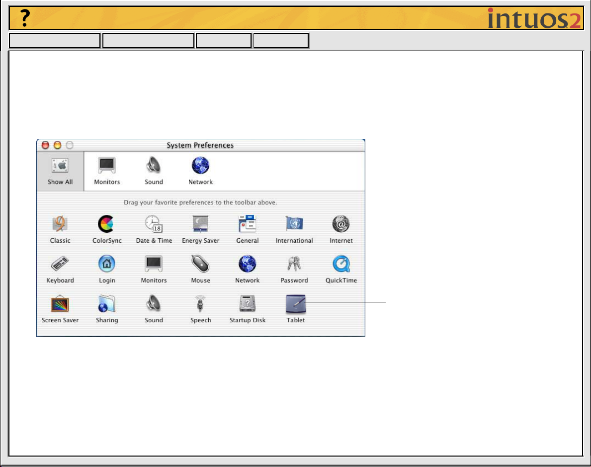
OPENING THE CONTROL PANEL
To open the control panel in OS X:
1. In the F
2. Open the W
, select the GO menu and choose A
INDER
ACOM
folder and double-click on the tablet icon.
PPLICATIONS
.
To open the Wacom control panel,
double-click here with the tool you
wish to customize.
To open the control panel in OS 8 and 9:
Open the control panel with the Intuos2 tool you wish to
customize.
1. Using your Intuos2 tool, open the Apple menu and choose C
2. Double-click on the tablet icon.
ONTROL PANELS.
Page 3
Help
Contents Back
<< >>
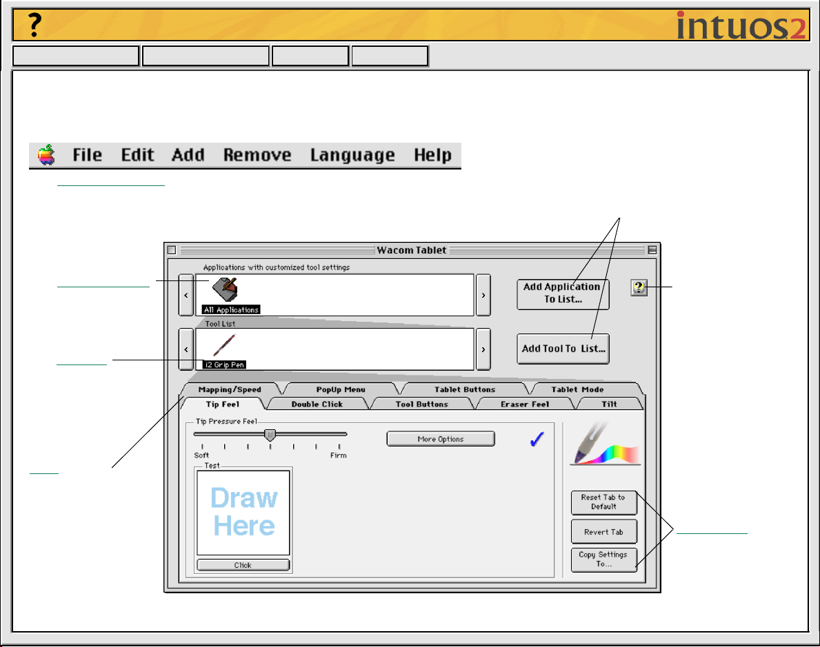
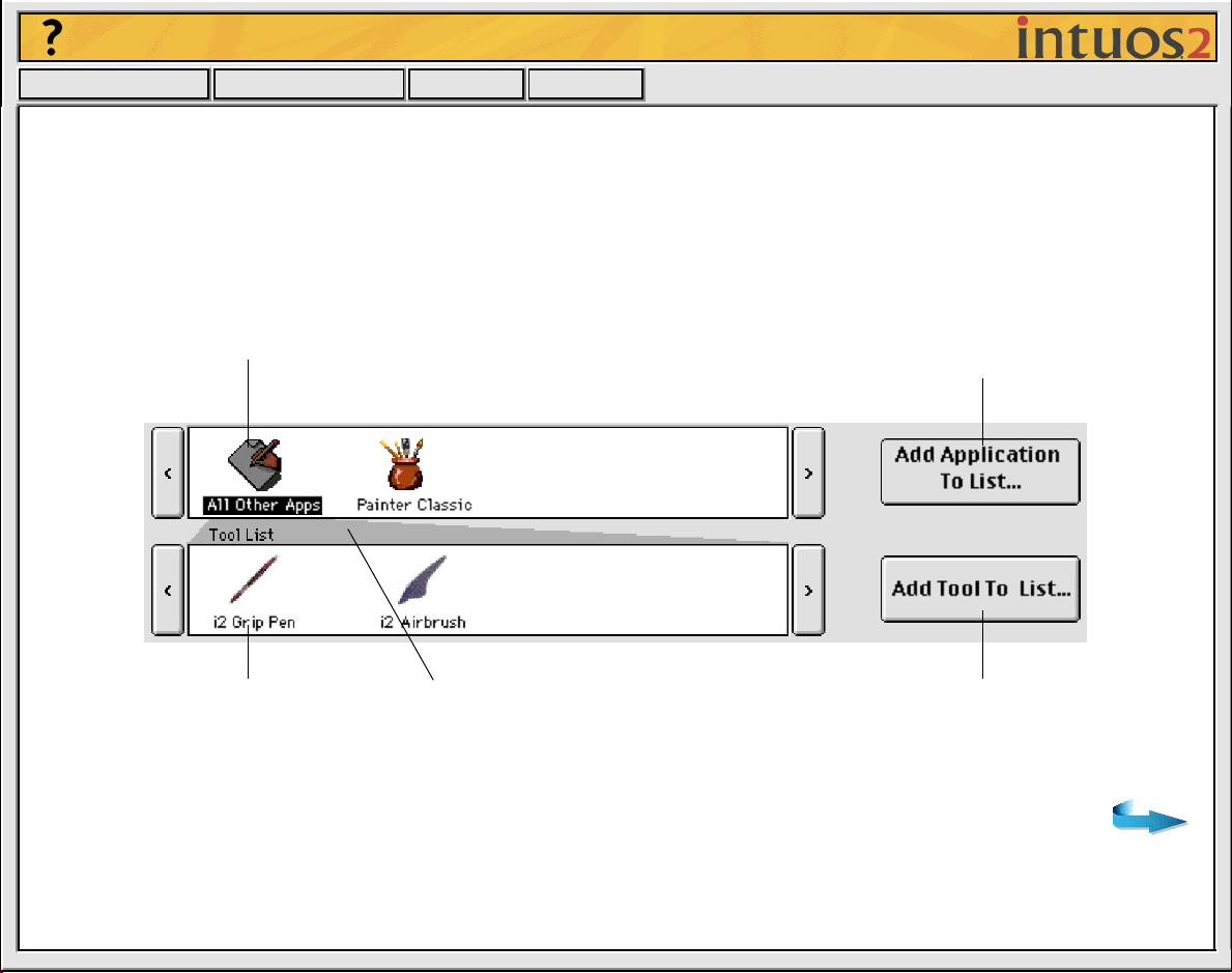
CONTROL PANEL FEATURES
Use the Wacom control panel to customize your Intuos2 Professional Graphics Tablet.
The Pull-Down Menus access many control panel features.
The Application List
displays applications
with customized
settings.
The Tool List
displays tools that
are customized for
the above selected
application.
These buttons add an application
or tool to the lists at the left.
The Help button
displays online
Help.
Tabs display
settings for the
selected application
and selected tool.
Tab buttons
apply only to the
selected tab.
Page 4
Help
Contents Back
<< >>
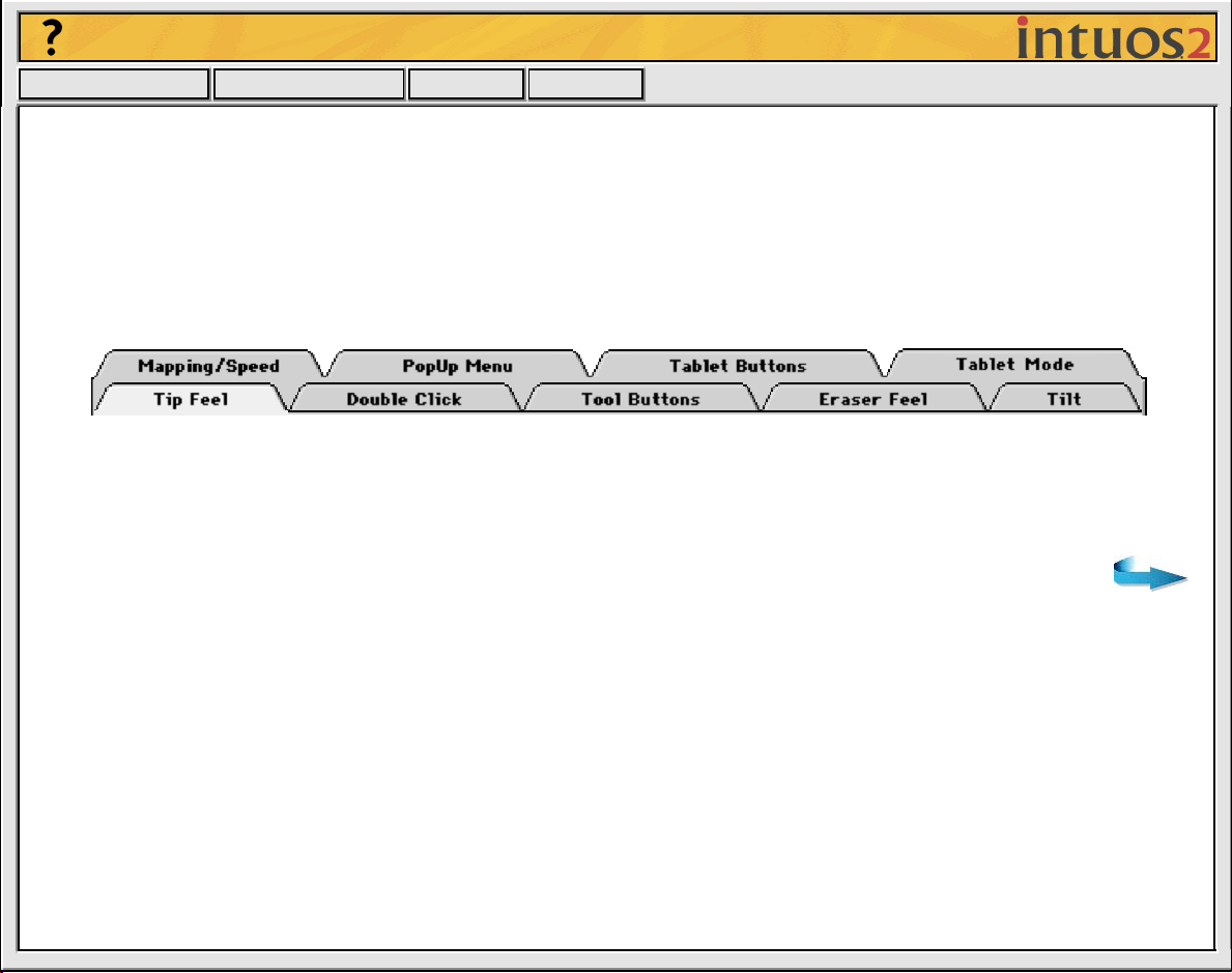
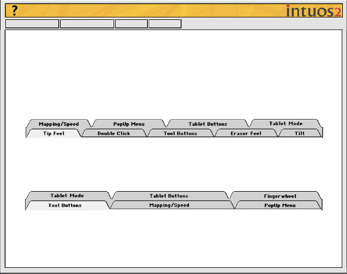
TABS
The tabs allow you to customize your Intuos2 tablet and tools. When you open the control panel with an
Intuos2 tool, the tool is automatically selected in the T
If the T
OOL LIST
has more than one tool, you can select a different tool to customize and the appropriate
tabs will display for that tool.
These tabs are displayed for the Intuos2 Pen or Airbrush.
Note:
The A
PPLICATION LIST
is for advanced users; it is not necessary to select or add applications to
customize your Intuos2 tool(s).
OOL LIST
and the appropriate tabs are displayed.
Page 5
Help
Contents Back
<< >>
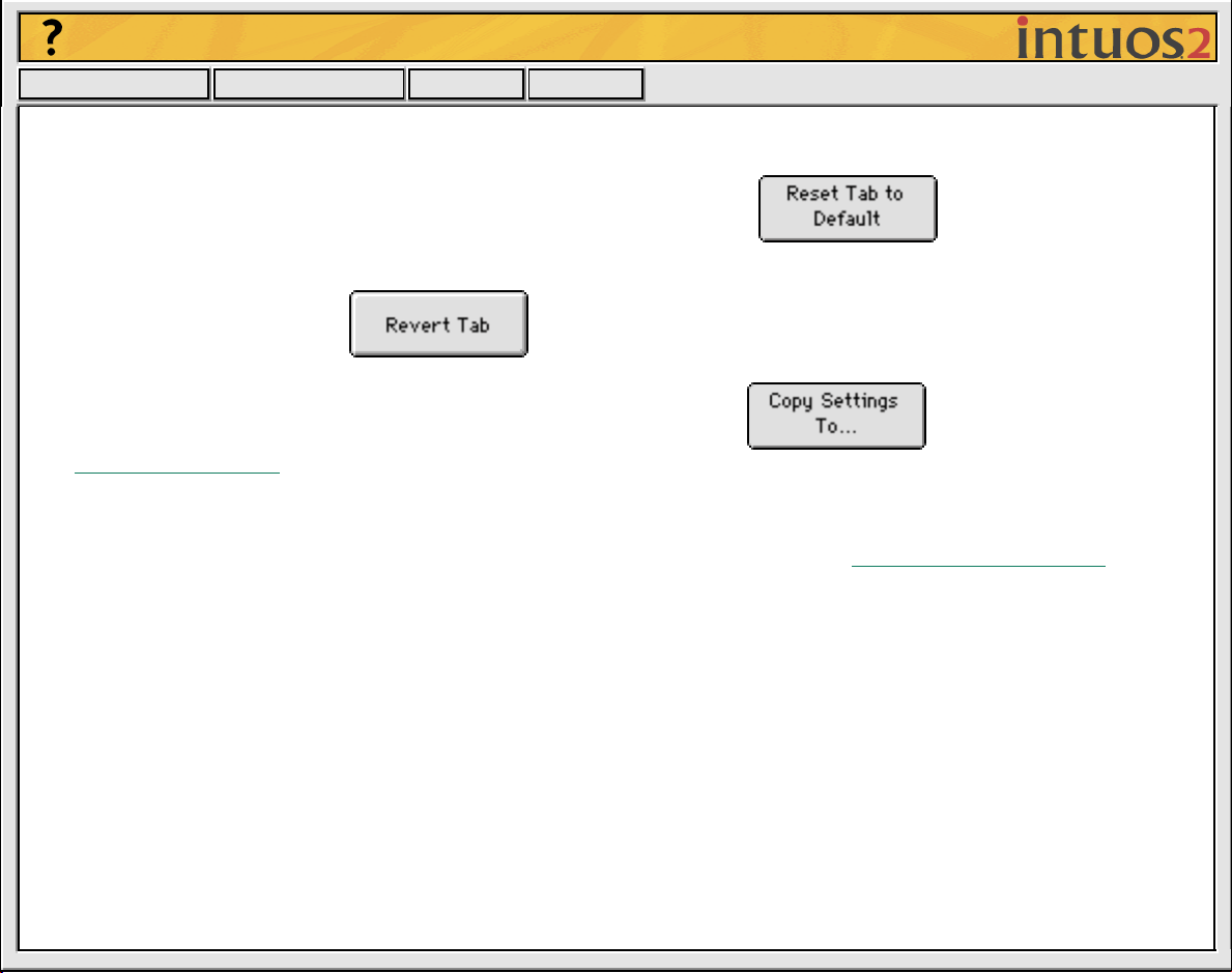
Tab buttons apply only to the selected tab:
• To set the currently open tab to its factory default values, click
• If you have changed settings on a tab and want to return the tab to the last state when the control
panel was opened, click
• To copy settings from one tool or application to another, click This will display the
Cop
y Settings To... dialog box.
As you explore the control panel tabs, experiment with different settings to find what works best for you.
You can always click R
ESET TAB TO DEFAULT
return a tab to the last state when the control panel was opened. Refer to Customizing
to return to the factory settings. Or, click R
EVERT TAB
to
Your Tools for
detailed information on working with tabs.
Page 6
Help
Contents Back
<< >>
CONTROL PANEL LISTS
Located in the upper portion of the control panel, the A
PPLICATION LIST
and T
different tablet and tool settings for individual applications. For example, you might set your pen tip for a
soft feel in Painter and a firm feel in all other applications.
The APPLICATION LIST displays applications that
have custom tool settings associated with them.
Click to add an installed application to the
APPLICATION LIST. You can customize tool
settings for the selected application.
OOL LIST
allow you to create
The TOOL LIST displays tools
that can be customized for the
application selected above.
Your current selections are
highlighted. Wedges emphasize the
relationship between tab settings and
the selected tool and application.
Click to add an Intuos2 tool to
the TOOL LIST. You can
customize the tool for the
above selected application.
Page 7
Help
Contents Back
• When you first install your Intuos2 Professional Graphics Tablet, the A
A
PPLICATIONS
• The T
OOL LIST
icon. This contains tablet and tool settings for all of your applications.
displays an icon for each Intuos2 tool that has been used on the tablet. Each Intuos2
<< >>
PPLICATION LIST
displays the ALL
tool that is used on the tablet will automatically appear in the Tool List. However, the Wacom control
panel settings must be saved before a tool is permanently added to the list. See Adding a Ne
w Tool f or
more information.
When you are ready to create custom settings for individual applications, see W
orking with Application-
Specific Settings.
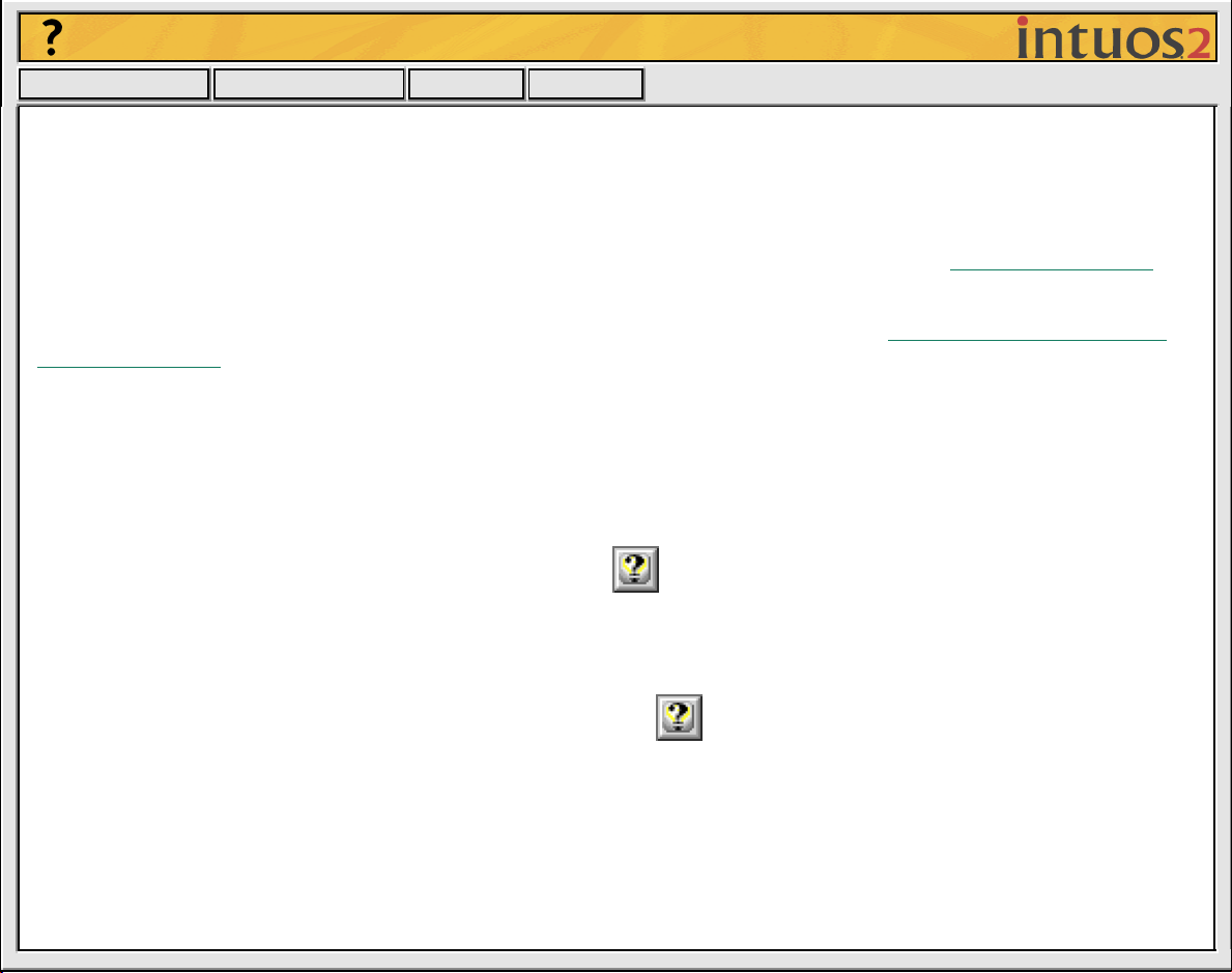
CONTROL PANEL BUTTONS
The control panel buttons are common to the entire control panel.
• To exit the control panel, either click on the close bo x (located on the window title bar), or select Q
C
LOSE
from the F
• To display online Help for the control panel, click Or, you can choose H
down menu.
Balloon Help, which provides quick information and useful tips, is also available for most control panel
items. To access balloons, turn them on by selecting S
individual dialog boxes is available by clicking on the button in the specific dialog box.
ILE
menu.
HOW BALLOONS
ELP
from the H
... from the H
ELP
menu. Help for
ELP
UIT
or
pull-
Page 8
Help
Contents Back
<< >>
CUSTOMIZING YOUR T OOLS
To change tool settings, open the control panel using the tool you wish to customize. The tool will
automatically be selected in the T
settings for a diff erent tool, select it from the T
T
ABLET BUTTONS
, and T
ABLET MODE
PEN AND AIRBRUSH TABS
If the selected tool is an Intuos2 Grip Pen or Airbrush, the following tabs are displayed:
2D MOUSE AND 4D MOUSE TABS
If the selected tool is a 2D Mouse or 4D Mouse, the following control panel tabs are displayed:
OOL LIST
, and the appropriate tabs will be displayed. To customize
OOL LIST
by clicking on its icon. Note that the POP-UP M
tab settings are not tool-specific and changes apply to all tools.
ENU
,
Page 9
Help
Contents Back
<< >>
CUSTOMIZING PEN AND AIRBRUSH SETTINGS
Customizing your W acom input tool is easy. First open the W acom control panel using the tool y ou wish to
customize. The tool will be selected in the T
tab and change settings using the available options. To customize settings for a different tool, select it
from the T
OOL LIST
by clicking on its icon.
ADJUSTING
ADJUSTING DOUBLE-CLICK
CUSTOMIZING TOOL BUTTONS
ADJUSTING ERASER FEEL
CUSTOMIZING TILT SENSITIVITY
TIP FEEL
OOL LIST
, and the appropriate tabs will be displayed. Select a
Page 10
Help
Contents Back
<< >>
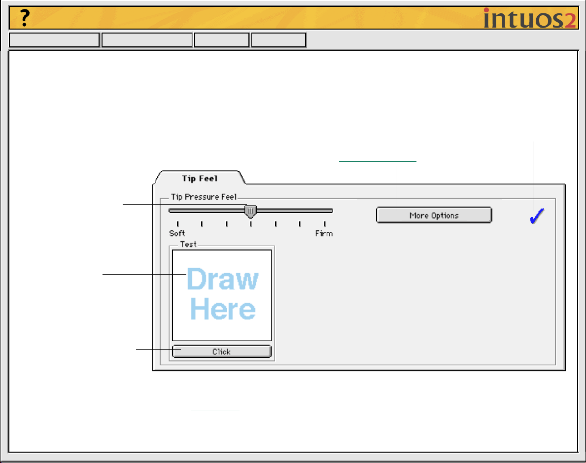
ADJUSTING TIP FEEL
To adjust the sensitivity of your Intuos2 P en or Airbrush tip , select the TIP F
strokes or to click with a light touch, use a soft tip setting. For maximum control while drawing thin lines,
use a firm tip setting.
A checkmark appears when advanced settings are in effect.
Toggles to the advanced options display.
Drag the slider to a
softer or firmer setting.
Make several pen
strokes to test the
current pressuresensitivity setting.
EEL
tab. To create broad brush
Click here with your pen
tip to test the current click
pressure setting.
Note: For all screen shots of tabs, the tab buttons are omitted in order to save space.
Page 11
Help
Contents Back
<< >>
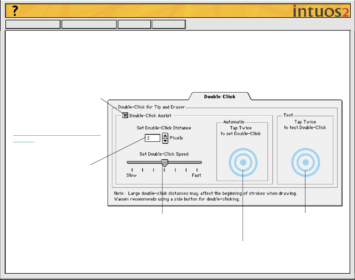
ADJUSTING DOUBLE-CLICK
Double-clicking with the pen tip can be made easier b y e xpanding the tap area that accepts a doub le-clic k
(the double-click distance) and reducing the speed required to perform a double-click. This can be set in
the D
OUBLE CLICK
some drawing applications, W acom recommends setting a small doub le-click distance and using the lo wer
side switch to double-click.
Use custom double-click settings
when checked.
Note: DOUBLE-CLICK ASSIST can
be enabled for some applications
and disabled for others. See
Working with Application-Specific
Settings for more information.
Enter a number from 1 to 25
pixels or click the up and down
arrows to increase or decrease
double-click distance.
tab. Because a large double-click distance may adversely affect your brushstrokes in
Drag the slider to change the double-click speed.
A slower speed makes double-clicking easier.
Tap twice on this icon with your pen tip to
automatically set double-click distance and speed
based on the way you normally double-click.
Double-click on the target
to test your settings before
applying them.
Page 12
Help
Contents Back
<< >>
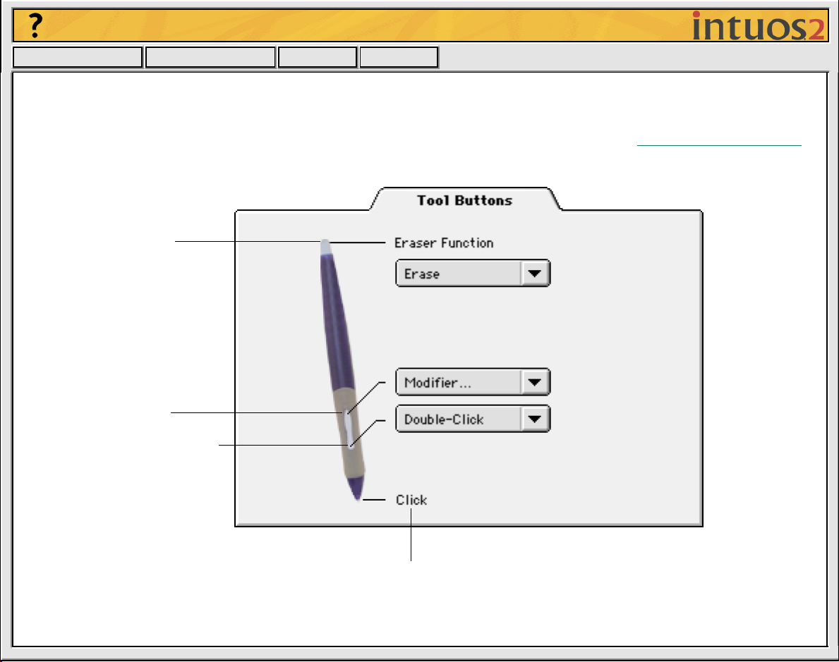
CUSTOMIZING T OOL BUTTONS
Select the T
Intuos2 Pen or Airbrush. If you are using an airbrush, you can also customize the fingerwheel sensitivity.
For each tool button, a pull-down menu enables you to choose the function that will be performed.
Select the function to perform
when using the eraser.
Select the function to
perform when pressing
the upper side switch.
Select the function to perform
when pressing the lower side
switch.
OOL BUTTONS
tab to change the functions assigned to the eraser, side switch, and tip of your
Click here to change the function assigned to the pen
tip. The tip must be set to click in order to draw in most
graphics applications.
Page 13
Help
Contents Back
<< >>
Button Functions
Each button has a pull-down menu that allo ws you to choose the function that will be performed when the
button is pressed. The following list describes all available functions. However, some options are not
available for all buttons or tools.
•
C
LICK
.
Default setting for the Intuos2 Pen or Airbrush tip. This option simulates a mouse button click.
Be sure at least one button performs this function so you can always navigate and click.
•
D
OUBLE-CLICK
pressing the switch simulates a mouse button double-click. For easier double-clicking, use this
function instead of tapping twice with your pen or airbrush tip.
•
C
LICK-LOCK
lock. Press the button again to release click lock. Click lock is useful for dragging objects or selecting
blocks of text.
.
Default setting for the lower position of the side switch. When this option is selected,
.
Simulates holding down the mouse button. Press the tool button once to initiate click
Page 14
Help
Contents Back
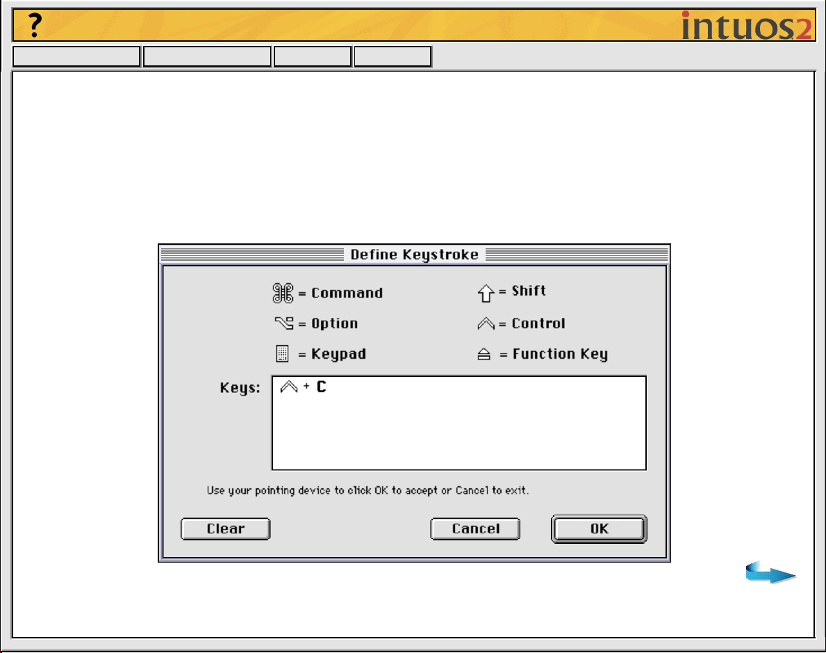
EYSTROKE.... Enables you to simulate a series of keystrokes. When you select this option, the
•
K
D
EFINE KEYSTROKE dialog box appears. There, you can enter a keystroke or keystroke sequence to
<< >>
play back. Keystroke combinations can include letters, numbers, function keys (such as F3) and
modifier keys (such as S
HIFT, OPTION, COMMAND, and CTRL). After defining a keystroke sequence,
click OK.
Important:
Because the RETURN key can be selected as a defined keystroke, it cannot be used to
select OK. You must use a tool to click on the OK button.
Page 15
Help
Contents Back
<< >>
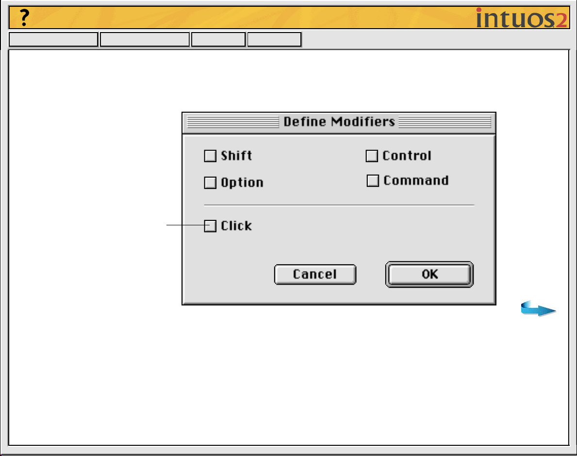
• MODIFIER.... Enables you to simulate modifier key(s) (such as SHIFT, OPTION, COMMAND, and CTRL).
Many applications use modifier keys to constrain the size or placement of objects. If you select this
option, the D
You can select the CLICK box plus
one or more modifier key options
to define the function you want
your tool button to simulate.
EFINE MODIFIERS dialog box appears. There, you select the modifier key(s) to simulate.
Page 16
Help
Contents Back
<< >>
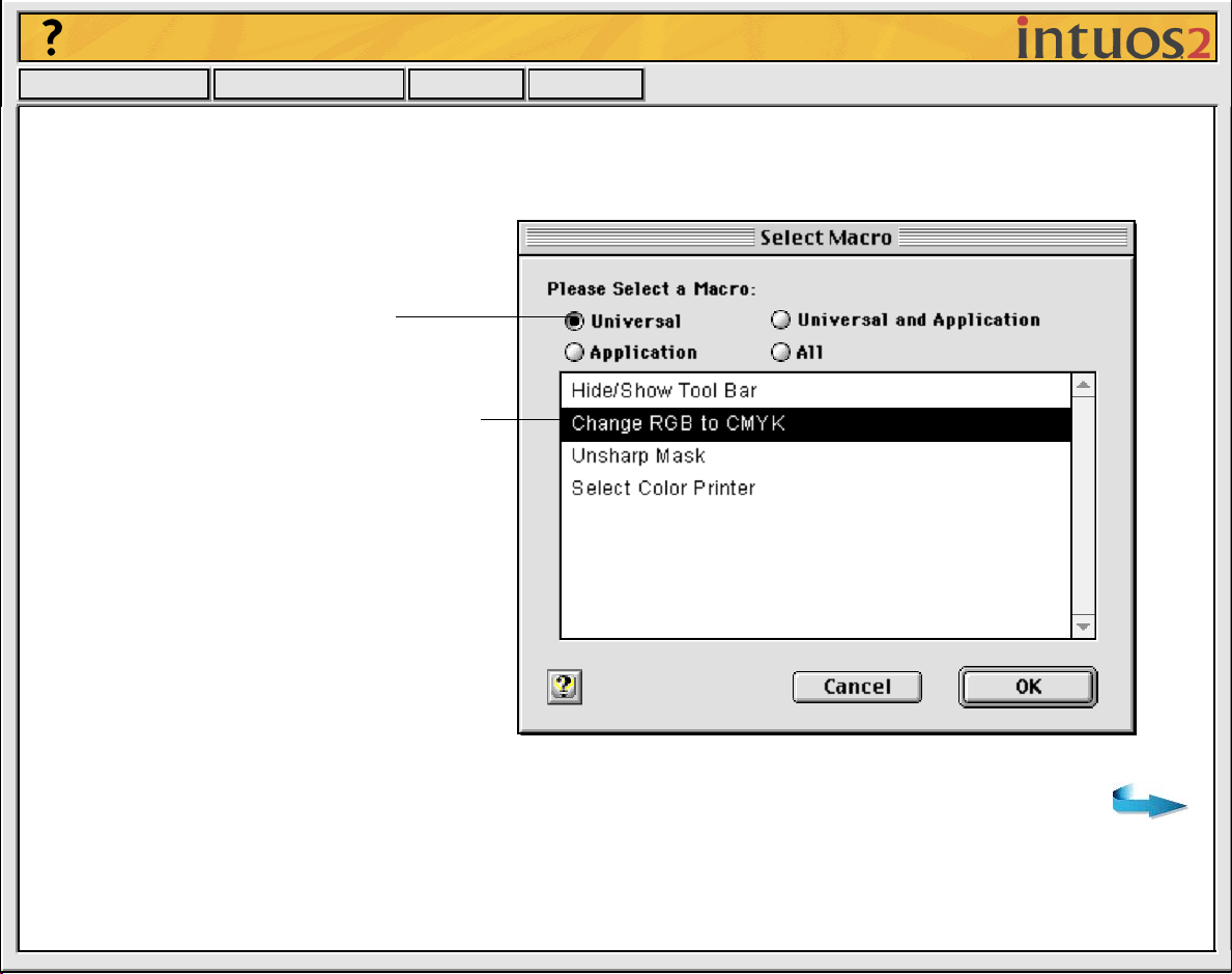
• MACRO.... Enables you to play a macro sequence. When you select this option, the SELECT MACRO
dialog box appears. There, you can select a predefined macro to play back. After selecting a macro,
click OK.
Choose the macro type.
Select the macro you wish to use.
Note: Before you can add macros, you must first create
them with a third-party macro application, such as QuicKeys.
Page 17
Help
Contents Back
<< >>
• PRESSURE HOLD. Sets a button so that, when pressed, the pressure is locked at the current pressure
level until the button is released. For example, you can paint with pressure-sensitivity until you reach
the brush size that you like. You can then press the button and continue painting with the same size
brush until the button is released.
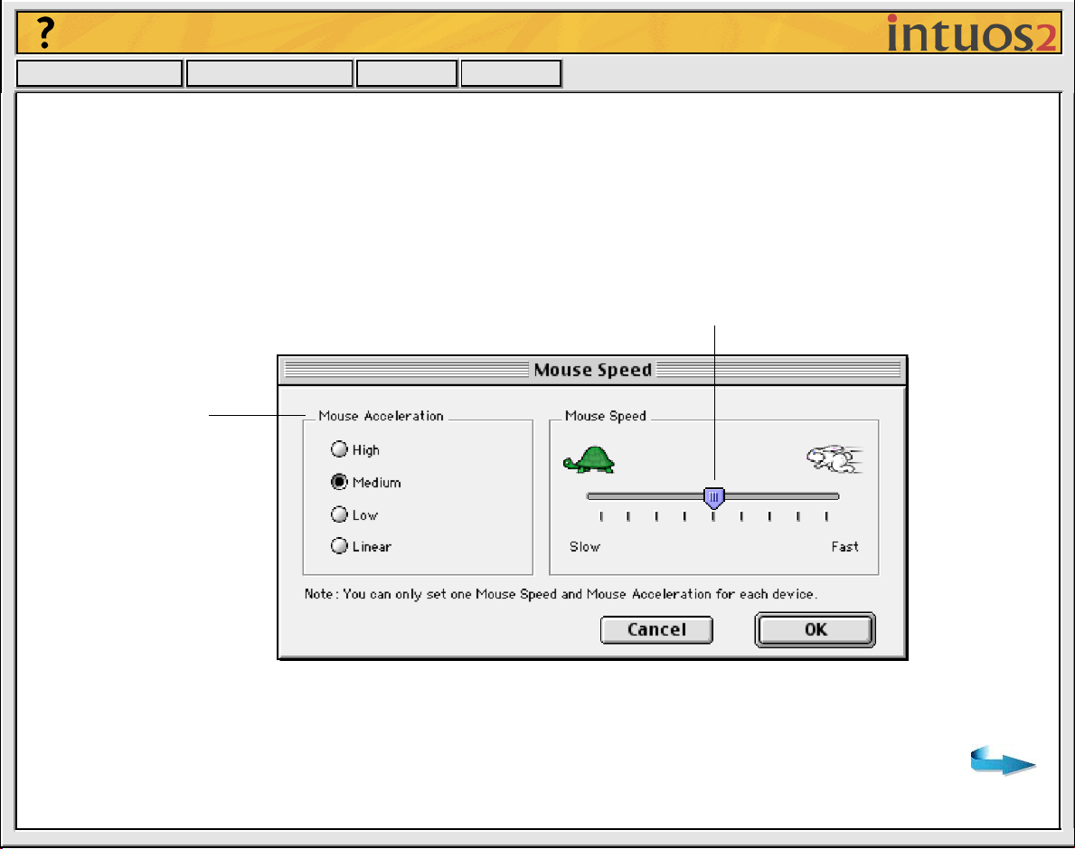
• M
ODE TOGGLE.... Toggles between Pen Mode and Mouse Mode. When first setting a tool button to
M
ODE TOGGLE..., the MOUSE SPEED dialog box is displayed where you can adjust the mouse
acceleration and speed.
Sets the screen cursor speed when in MOUSE MODE.
Sets the screen cursor
acceleration when in
MOUSE MODE.
Note: Mouse speed settings can be accessed from a number of different locations
within the control panel. However, for each input tool and application that you are
customizing, only one MOUSE SPEED and ACCELERATION setting can be made.
Page 18
Help
Contents Back
<< >>
• POP-UP MENU. Displays a Pop-up Menu on your screen. See Customizing the Pop-up Menu for more
information.
• E
RASE. Default setting for the eraser.
• I
GNORED. (Intuos2 Pens and Airbrush only.) Disables the button function.
• A
PPLICATION DEFINED. (2D Mouse, 4D Mouse, or Lens Cursor only.) Only the button number is
reported to your application. Use this setting when using applications that ha v e b uilt-in support for tool
buttons. For example, CAD programs that support tablets can assign their own functions to a button.
Page 19
Help
Contents Back
<< >>
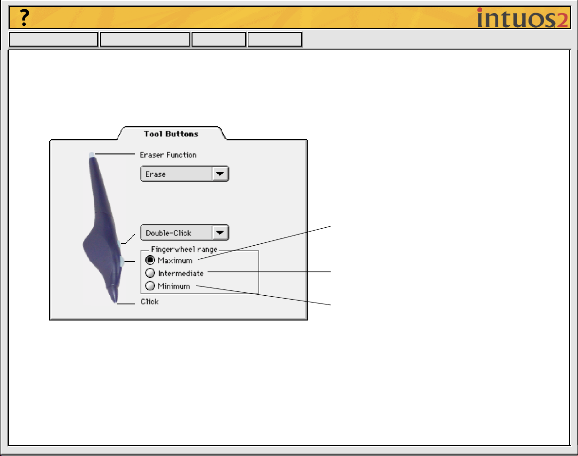
Airbrush Settings
The Intuos2 Airbrush is equipped with a drawing tip, a fingerwheel, a single side switch, and an eraser.
Button functions are set in the same manner as with the Intuos2 Pen. Additionally, the fingerwheel
sensitivity range can be customized to suit your preference.
MAXIMUM is the default setting, and requires
you to move the wheel over its full range to
achieve maximum effect.
INTERMEDIATE requires a medium amount of
wheel movement to achieve maximum effect.
MINIMUM requires the least amount of wheel
movement to achieve maximum effect.
In supporting applications, the fingerwheel can be used to control ink flow, brush size, opacity, or other
variables. Reducing the fingerwheel range allows you to achieve the same effect with less finger
movement. Move the wheel forward for less effect and move it back for more effect.
Visit Wacom’s web site for a list of applications that currently support airbrush features.
Page 20
Help
Contents Back
<< >>
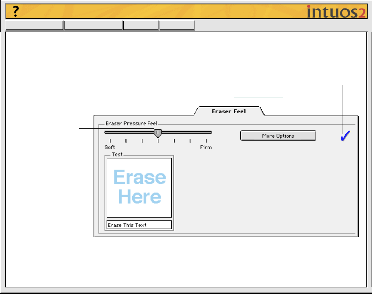
ADJUSTING ERASER FEEL
To adjust the sensitivity of your Intuos2 P en or Airbrush eraser, select the ERASER FEEL tab. To erase with
a broad stroke or to click with a light touch, use a soft tip setting. For maximum control while erasing, use
a firm eraser setting.
A checkmark appears when advanced settings are in effect.
Toggles to the adv
Drag the slider to a
softer or firmer setting.
Using your eraser, test
the current eraser
pressure-sensitivity
setting by erasing here.
Check the eraser click
pressure setting by using
the eraser to select and
delete this text.
anced options display.
Page 21
Help
Contents Back
<< >>
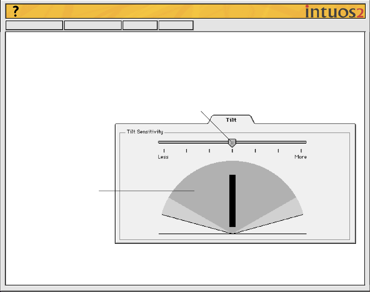
CUSTOMIZING TILT SENSITIVITY
To adjust the tilt sensitivity of your Intuos2 P en or Airbrush, select the TILT tab . Tilt sensitivity controls how
far you have to tilt the tool to produce the maximum tilt effect in your application. You need to tilt the pen
less at high sensitivity than at low sensitivity to get the full tilt value reported to your application.
Like pressure-sensitivity, tilt can be assigned to control brush characteristics. Your tilt setting applies to
both the tip and eraser of your pen or airbrush.
Drag the slider to increase or decrease pen
tilt sensitivity. The default setting is LESS.
The tilt display graphically shows
the reported tilt angle of your
pen or airbrush.
Place your pen or airbrush
vertically on the tablet, and tilt it
from side to side and forward
and backward. The graphic
lever moves to indicate the
amount and direction of tilt
reported to the application.
Note: Tilt is direction-sensitive
and can be used in some
applications to control brush
orientation.
Visit Wacom’s web site for a list of applications that currently support tilt.
Page 22

Help
Contents Back
<< >>
CUSTOMIZING MOUSE TOOL SETTINGS
Customizing your W acom input tool is easy. First open the W acom control panel using the tool y ou wish to
customize. The tool will be selected in the T
tab and change settings using the available options. To customize settings for a different tool, select it
from the T
OOL LIST by clicking on its icon.
CUSTOMIZING THE 2D MOUSE
CUSTOMIZING THE 2D MOUSE FINGERWHEEL
CUSTOMIZING THE 4D MOUSE AND LENS CURSOR
CUSTOMIZING THE 4D MOUSE FINGERWHEEL
OOL LIST, and the appropriate tabs will be displayed. Select a
Page 23

Help
Contents Back
<< >>
CUSTOMIZING THE 2D MOUSE
To modify your 2D Mouse button settings, select the TOOL BUTTONS tab.
Select the function to perform when pressing a button.
You can select a function to
perform for each button from the
button pull-down menus. Refer to
Button Functions for a description
of the available options.
The 2D Mouse buttons are
chordable; you can press two or
more buttons simultaneously and
the functions will occur. For
example, if you program one
button to simulate the Ctrl key
and another to simulate a Z
keystroke, when you press both
buttons a Ctrl+Z is simulated.
Page 24

Help
Contents Back
<< >>
CUSTOMIZING THE 2D MOUSE FINGERWHEEL
To customize your 2D Mouse fingerwheel, choose the FINGERWHEEL tab.
Sets the fingerwheel to scroll
the selected number of lines
for each notch of fingerwheel
movement (in most
applications). Enter a value
(1 to 15) to set the amount of
movement. Roll the
fingerwheel forward to scroll
up, and back to scroll down.
Sets the fingerwheel to scroll
one screen for each notch of
fingerwheel movement.
When checked, the functions
assigned for the forward and
backward direction of the
fingerwheel are exchanged.
Disables the fingerwheel function.
The KEYSTROKES radio button sets the fingerwheel to issue a keystroke for each
notch of wheel movement. This is useful when working with repetitive functions
(such as zooming in Photoshop, or moving forward and backward within your
internet browser). Clic k the appropriate S
The keystroke setting will be displayed in the UP or DOWN box.
ET... b utton to enter a ke ystroke function.
Page 25

Help
Contents Back
<< >>
CUSTOMIZING THE 4D MOUSE AND LENS CURSOR
To modify your 4D Mouse and Lens Cursor button settings, select the TOOL BUTTONS tab. As with the
Intuos2 Pen and Airbrush, you can select a function to perform for each button from the button pull-down
menus. Refer to Button Functions
Select the function to perform when pressing a button.
for a description of the available options.
When checked, the 4D Mouse or Lens Cursor functions
as a Button Box. See Creating a Button Box.
Page 26

Help
Contents Back
<< >>
Programming the 4D Mouse and Lens Cursor
The 4D Mouse and Lens Cursor buttons are chordable; y ou can press two or more b uttons simultaneously
and the functions will occur. For example, if y ou progr am one b utton to simulate the C
to simulate a Z keystroke, when you press both buttons a C
TRL+Z is simulated.
TRL key and another
Creating a Button Box
You can check the BUTTON BOX option to disable cursor tracking when using the 4D Mouse or Lens
Cursor. This gives you the freedom to draw with the pen without ha ving to reach for the keyboard to enter
a keystrok e . Instead, you might press the 4D Mouse or Lens Cursor buttons to perform defined keystrok e
functions. Note that if you use your 4D Mouse or Lens Cursor as a Button Box, it must remain on the
tablet’s active area to function.
Page 27

Help
Contents Back
<< >>
CUSTOMIZING THE 4D MOUSE FINGERWHEEL
To customize your 4D Mouse fingerwheel, choose the FINGERWHEEL tab.
Sets the fingerwheel sensitivity. With MAXIMUM selected, a small
Sets the 4D Mouse fingerwheel for scrolling
functionality. Roll the fingerwheel forward to
scroll up, and back to scroll down.
Provides fingerwheel information to a
supporting application. Some applications
may use the fingerwheel for 3D na vigation,
zooming, audio or video jogging, etc.
The KEYSTROKES radio button sets the
fingerwheel to issue repeated keystroke
events to the application. You can adjust the
rate of repetition by how far you move the
fingerwheel forward or backward. This is
useful when working with repetitive functions
(such as zooming in Photoshop or moving
forward and backward within your internet
browser). Clic k the appropriate SET... b utton
to enter a keystroke function. The keystrok e
setting will be displayed in the U
box.
When checked, the functions assigned for
the forward and backward direction of the
fingerwheel are exchanged.
P or DOWN
movement of the fingerwheel will create a large effect. With STANDARD
selected, a small movement of the fingerwheel will create a small effect.
Disables the fingerwheel.
Simulates pressure. Move the
fingerwheel forward or backwards
to increase pressure.
Page 28

Help
Contents Back
<< >>
TABLET TO SCREEN MAPPING
To change the relationship between tool movement on your tablet and cursor movement on the screen,
select the M
M
ODE, which means that each point on the tablet maps to a corresponding point on the screen. In PEN
M
ODE, the MAPPING/SPEED tab looks like this:
Positioning Mode. In PEN MODE, the screen
cursor moves with absolute positioning.
Select the
Tablet Area
for drawing.
APPING/SPEED tab. The default POSITIONING MODE for Intuos2 Pens and the Airbrush is PEN
Select the Orientation of your tablet.
Note: Except for tablet orientation, all mapping
settings apply to a specific Intuos2 tool.
Display Area.
Select a monitor
area for tablet to
screen mapping.
QuickPoint Mode. “Splits” tablet into two
independent areas: a large area for drawing
and a small area for quick navigation. Both
areas are mapped to the display area.
Aspect. Select a
tablet to screen
mapping
relationship.
Click here to display Advanced Mapping options.
Page 29

Help
Contents Back
<< >>
The default POSITIONING MODE for the 2D Mouse, 4D Mouse, and Lens Cursor is MOUSE MODE.
With M
Positioning Mode. In MOUSE MODE, the screen
cursor moves with relative positioning.
OUSE MODE selected, the MAPPING/SPEED tab looks like this:
Select the Orientation of your tablet.
Sets the
screen cursor
acceleration
when in
MOUSE MODE.
Select a slower or faster screen cursor speed when in MOUSE MODE.
Page 30

Help
Contents Back
<< >>
POSITIONING MODE
The POSITIONING MODE controls how the screen cursor moves.
• In Pen Mode, wherever you place an Intuos2 tool on the tablet, the cursor jumps to the corresponding
point on the screen. This is the default setting for Intuos2 Pens and the Airbrush, and is required for
tracing.
• In Mouse Mode, the screen cursor is positioned like a mouse, requiring a “pick up and slide” motion to
move the cursor on the screen. This is the default setting for the 2D Mouse, 4D Mouse, and Lens
Cursor.
By default the pen and airbrush are set to P
set to M
Note
OUSE MODE for navigation.
: You can also switch between Pen Mode and Mouse Mode by clicking on the appropriate tablet
button, or by using the screen Pop-up Menu. See Customizing
up Menu for more information.
EN MODE for drawing, and the 2D Mouse and 4D Mouse are
Tablet Buttons and Customizing the Pop-
Page 31

Help
Contents Back
<< >>
ORIENTATION
If you want the tablet men u b uttons on the side or the bottom of your tab let, or if y ou are working with a tall
monitor, you can rotate the tablet to one of the following orientations:
• L
ANDSCAPE. Tablet orientation is horizontal, with tablet buttons at the top. This is the default setting.
• P
ORTRAIT. Rotate the tablet 90 degrees clockwise from landscape orientation. The tablet orientation
will be vertical, with the tablet buttons on the right side.
• L
ANDSCAPE FLIPPED. Rotate the tablet 180 degrees from landscape orientation. The tablet will be
upside down, with the tablet buttons near the bottom.
• P
ORTRAIT FLIPPED. Rotate the tablet 90 degrees counter-clockwise from landscape orientation.
The tablet orientation will be vertical with the tablet buttons on the left side.
After making changes, verify you have the correct setting for your tablet orientation. Do this by moving
your tool “up” on the tablet—the cursor should move up as well.
Note:
The orientation you select applies to all tools and applications.
Page 32

Help
Contents Back
<< >>
ASPECT
Aspect defines the constraints of the tablet to screen relationship. ASPECT options include:
• ONE TO ONE. Sets a 1:1 scale between the tablet and
the display. Moving your tool one inch on the tablet will
move the cursor one inch on the screen. A tr aced image
appears the same size as the original image on your
display screen. A screen resolution of 72 DPI is used in
calculations. If your monitor is set to use a different
screen resolution, a 1:1 scale will not be maintained.
• PROPORTIONAL. Maintains correct vertical and
horizontal proportions between the tablet and display.
A traced image appears proportionally correct on your
display, but may be smaller or larger than the original
image.
• TO FIT. Correct scale or proportions are not maintained.
The selected tablet area is mapped to the selected
display area. A traced image ma y appear stretched, and
may be smaller or larger than the original image. This is
the default setting for all tools.
Page 33

Help
Contents Back
<< >>
TABLET AREA
These settings allow you to define the tablet area that will be mapped to the display area.
Uses the entire active area of the tablet for tablet
to display mapping. This is the default setting.
Displays the PORTION OF TABLET dialog box where
you can select a portion of the tablet’s activ e area
for tablet to display mapping.
Divides the tablet into a drawing area and a
QuickPoint area for quick navigation. (For
Intuos2 9x12/A4-regular and larger tablets.)
Sets the QuickPoint area to the
lower right corner of the tablet.
Sets the QuickPoint area to the
lower left corner of the tablet.
Page 34

Help
Contents Back
• PORTION OF TABLET.
Enter coordinates to select the tablet area.
• Select UNITS of measure for the displayed
values. A count equals one line of tablet
resolution.
• Enter values for the TOP, LEFT, BOTTOM,
and RIGHT boundary of the tablet area.
Values are measured from the top left
corner of the tablet’s active area.
Drag corners of the foreground graphic to
select the tablet area. The background
graphic represents the entire active tablet
area. Values in the ENTER COORDINATES
text boxes change accordingly.
Use your tool on the tablet to select the tablet
area.
• Select the CLICK TO DEFINE TABLET AREA
button.
• Follow the MESSAGE prompts to set the
portion of your tablet that will be used for
mapping.
<< >>
Note: As y ou define PORTION OF TABLET, be sure to review the MESSAGE prompts that ma y appear.
Page 35

Help
Contents Back
<< >>
• QUICKPOINT MODE. This option (available for Intuos2 9x12/A4-regular and larger tablets) divides the
tablet into two independent areas: a large area for drawing, and a small area for quick navigation.
QuickPoint Mode can also be selected and deselected using the tablet buttons or screen Pop-up
Menu. See Customizing
Tablet Buttons and Customizing the Pop-up Menu for more information.
The QuickPoint area is always mapped to the entire display area (to all monitors on multiple monitor
systems). The drawing area is set to Pen Mode and mapped according to the D
A
SPECT settings.
9x12/A4-regular tablet
12x12/A4-oversize tablet
QuickPoint area
set to lower left
corner of tablet.
Drawing
areas
9x12/A4-regular tablet
12x12/A4-oversize tablet
ISPLAY AREA and
QuickPoint area
set to lower right
corner of tablet.
12x18/A3 tablet
Note: The QuickPoint area and drawing area are indicated by crop marks on the tablet overlay. All QuickPoint
and drawing areas have the same aspect as a standard monitor (aspect ratio of 3:4).
12x18/A3 tablet
Page 36

Help
Contents Back
<< >>
DISPLAY AREA
The DISPLAY AREA options allow you to define which portion of the display screen your tablet will map to.
• ENTIRE DISPLAY. Select this option to access the entire display. This is the default setting. If more
than one monitor is in use, a pull-down menu is displayed with options for selecting A
individual monitors.
• P
ORTION OF DISPLAY.... This option allows you to select a portion of the display for tablet to screen
mapping. Selecting P
Enter coordinates to select the screen area.
• Select UNITS of measure for the displayed values.
• Enter values for the TOP, LEFT, BOTTOM, and RIGHT
boundary of the display screen area. Values are
measured from the top left corner of the display.
Drag corners of the foreground graphic to select the
screen area. The background graphic represents the
entire screen area. Values in the ENTER COORDINATES
text boxes will change accordingly.
ORTION OF DISPLAY... brings up the PORTION OF DISPLAY dialog box.
LL MONITORS or
Move the screen cursor to select the screen area.
• Select the CLICK TO DEFINE SCREEN AREA button.
• Follow the MESSAGE prompts to set the portion of
your display screen that will be used for mapping.
Note: As you define PORTION OF DISPLAY, be sure to
review the MESSAGE prompts that may appear.
Page 37

Help
Contents Back
<< >>
CUSTOMIZING THE POP-UP MENU
Select the POP-UP MENU tab to customize the available functions on the Pop-up Menu list. The Pop-up
Menu list may include predefined macros, keystroke functions, and mapping options.
To display the Pop-up Menu, set one of your tool buttons to the P
push that button, the Pop-up Menu is displayed. Select items in the Pop-up Menu by clicking on them.
To close the Pop-up Menu without making a selection, just click outside the Pop-up Menu.
Displays a list of functions that will appear in the Pop-up
Menu. To change the order of an item, drag it to a new
location (mapping options are moved as a group).
OP-UP MENU function. Whenever you
Adds a predefined macro to the menu
list. Before you can add macros, you
must first create them with a third-party
macro application.
Adds a keystroke macro to the menu list.
Displays the Mouse Speed dialog box where
you can set the screen cursor speed and
acceleration when in MOUSE MODE. If you
remove the PEN, MOUSE, and QUICKPOINT
mode options from the menu list, this button is
replaced with the ADD MAPPING OPTIONS
button, which enables you to add PEN,
MOUSE, and QUICKPOINT mode options back
to the POP-UP MENU list. The mapping option
you select from the Pop-up Menu is applied
only to the tool used to select it.
Removes the selected item(s) from the list.
Note: Pop-up Menu settings apply to all tools.
Page 38

Help
Contents Back
<< >>
ADD MACROS
To add a macro to the Pop-up Menu, clic k on the ADD MACRO... button. A dialog box will appear where you
can select the name of a macro function to add. You can also set different macros for different
applications. See W
Note:
Before you can add screen macros, you must first create them with a third-party macro application.
orking with Application-Specific Settings for more information.
ADD KEYSTROKES
To add a keystroke definition to the Pop-up Menu, click on the ADD KEYSTROKE... button. A dialog box will
appear where you can specify and name the keystroke function. You can also create different keystroke
functions for different applications. See W
orking with Application-Specific Settings for more information.
Page 39

Help
Contents Back
<< >>
SETTING MOUSE SPEED
To change the screen cursor acceleration and speed when in MOUSE MODE, click on the SET MOUSE
S
PEED... button (located on the POP-UP MENU tab) to display a dialog box where you can make your
adjustments. If you removed the P
button is replaced with the A
Q
UICKPOINT mode options back to the Pop-up Menu list.
Sets the screen cursor
acceleration when in
MOUSE MODE.
DD MAPPING OPTIONS button, which enables you to add PEN, MOUSE, and
EN, MOUSE, and QUICKPOINT mode options from the menu list, this
Sets the screen cursor speed when in MOUSE MODE.
Note:
from the T
M
The MOUSE SPEED dialog box will also appear when you first set a tool button to MODE TOGGLE...
OOL BUTTONS tab. For each input tool and application that you are customizing, only one
OUSE SPEED and ACCELERATION setting can be made.
Page 40

Help
Contents Back
<< >>
ADD MAPPING OPTIONS
Click on the Add Mapping Options button (when visible) to add the following mapping options to the
Pop-up Menu list: P
larger tablet) Q
EN MODE, MOUSE MODE, and (if you are working with a Intuos2 9x12/A4-regular or
UICKPOINT MODE.
REMOVING POP-UP MENU OPTIONS
To remove mapping option(s), macro(s), or keystroke function(s) from the Pop-up Menu list, select the
function(s) you wish to remov e and clic k the R
as a single item. Multiple options may be selected for removal by pressing the S
them.
EMOVE button. Mapping options must be added or removed
HIFT key and clicking on
Page 41

Help
Contents Back
<< >>
CUSTOMIZING TABLET BUTTONS
You can define different tablet button functions for each application, but not for the different Intuos2 tools.
To customize the tablet menu strip buttons, select the T
predefined functions have that function selected in their pull-down menu. The settings of other tablet
buttons are set to I
Choose the function to
perform when the tablet
button is selected.
Displays the predefined
function or keystroke
sequence. Otherwise,
this is left blank.
GNORED.
ABLET BUTTONS tab. By default, tab let b uttons with
To customize tablet button functions:
1. Select the button you wish to customize from the scrolling list.
Page 42

Help
Contents Back
<< >>
2. Select an item from the tablet button’s pull-down menu.
• K
EYSTROKE. Simulates a keystroke or keystroke combination.
• M
ACRO. Enables you to play a predefined macro sequence.
• P
RESSURE SOFT. Sets the pressure feel of the pen, airbrush, or eraser to a soft setting.
• P
RESSURE FIRM. Sets the pressure feel of the pen, airbrush, or eraser to a firm setting.
• P
RESSURE NORMAL. Returns the pressure feel of your tool to the factory default.
• P
EN MODE. Places your tool in Pen Mode.
• M
OUSE MODE.... Places your tool in MOUSE MODE. When first setting a tablet button to MOUSE
M
ODE..., the MOUSE SPEED dialog box is displayed where you can adjust the mouse acceleration
and speed.
• Q
UICKPOINT MODE. Divides the tablet into a QuickPoint area and a drawing area. This option is
only available for Intuos2 9x12/A4-regular or larger tablets.
• I
GNORED. Leaves the tablet button undefined. When a tablet button is set to IGNORED, the button
number does not appear on the display screen when an Intuos2 tool is moved over the button.
• D
EFAULT. Returns a button to its default settings. These settings match the predefined menu strip
functions.
• Back. Sets the button to emulate the back function within your internet browser.
• Forward. Sets the button to emulate the forward function with your internet browser.
• Stop. Sets the button to emulate the stop function within your internet browser.
• Refresh. Sets the button to emulate the refresh function within your internet browser.
After defining a new tablet button function, you may want to label the appropriate menu strip button
(with 6x8/A5 and larger tablets only). Lift the left edge of the tablet overlay and remove the menu strip.
Write the function name on the button with a pencil, and then replace the menu strip. Take care not to
damage the overlay or lose the menu strip.
Page 43

Help
Contents Back
<< >>
WORKING WITH MULTIPLE TOOLS
The Wacom control panel is designed to help you customize and keep track of your Intuos2 tool settings.
The tool you use to open the control panel is automatically selected, and the appropriate tabs for that tool
are displayed.
If application-specific settings have not been added, the ALL APPLICATIONS
icon is displayed and the tool settings apply for all applications.
The TOOL LIST displays
icons for tools that are
customized for the above
selected application.
Tab settings apply only
to the selected tool and
application.
Your current selections are highlighted. Wedges emphasize
the relationship between tab settings and the selected tool
and application.
Page 44

Help
Contents Back
<< >>
ADDING A NEW TOOL
When a new Intuos2 tool is placed on the tablet, it automatically appears in the TOOL LIST. However, the
Wacom control panel settings must be sa v ed before the tool is permanently added to the list. Whenever a
new Intuos2 tool is added it always uses the default settings for that tool, and not the custom settings of
other tools, even if they are identical devices.
There are several ways to add Intuos2 tools to the T
• When you use an Intuos2 tool on the tablet for the first time, it will automatically function with the
appropriate default settings. You can customize the tool by opening the Wacom control panel and
changing the tab settings. Your changes are permanently saved when you close the control panel.
When you place a second Intuos2 tool on the tablet, a new tool discovered message box appears.
This reminds you to open the Wacom control panel to permanently add the new tool to the T
(This message only appears if the Wacom control panel is not open. If the control panel is open, the
tool is automatically added to the list.)
• To manually add a new tool, click on the A
from the A
DD pull-down menu. In the ADD TOOL TO CUSTOMIZE dialog box, select ADD NEW TOOL... and
DD TOOL TO LIST... button or select TOOL TO CUSTOMIZE...
follow the prompts.
When you select a new tool that y ou hav e added to the T
are displayed. Any changes you may make to the tab settings will then apply to that tool.
OOL LIST:
OOL LIST.
OOL LIST, the appropriate tab settings for that tool
To remove a tool from the T
OOL LIST, select CUSTOMIZED TOOL... from the REMOVE men u. In the dialog bo x
that appears, select the tool to remove. Then select R
EMOVE COMPLETELY and click OK.
Page 45

Help
Contents Back
<< >>
USING MORE THAN ONE TOOL
Each Intuos2 tool features Tool ID, which makes each device unique. Any settings you customize in the
Wacom control panel apply only to the specific tool for which they were made.
If you have two identical Intuos2 tools, they will appear as numbered devices in the T
give each tool a different name. For example, you might name one “Drawing Pen” and the other “Paint
Brush”. To change the tool names, select R
ENAME TOOL... from the EDIT pull-down menu.
To use the same custom settings with two tools, click the Copy Settings To... button and choose the
settings you want to copy. For dissimilar tools (such as a pen and a 4D Mouse), only those settings
common to both tools (such as mapping settings) can be copied.
OOL LIST. You can
Page 46

Help
Contents Back
<< >>
WORKING WITH APPLICATION-SPECIFIC SETTINGS
You may wish to have different tool settings for a particular application. The APPLICATION LIST lets you
customize your Intuos2 tablet and tool settings for individual applications.
The APPLICATION LIST
displays icons for
applications with
customized settings.
The TOOL LIST displays
icons for tools that are
customized for the above
selected application.
Tab settings apply only
to the selected tool and
application.
Your current selections are highlighted. Wedges emphasize
the relationship between tab settings and the selected tool
and application.
Page 47

Help
Contents Back
<< >>
If application-specific settings have not been created, a single icon labeled ALL APPLICATIONS is display ed
in the A
PPLICATION LIST, and the tool settings displayed in the tabs are applied to all applications.
When a second application is added to the APPLICATION LIST, the ALL APPLICATIONS icon changes to ALL
O
THER APPS, and a new icon is displayed for the new application settings.
If you select the ALL OTHER APPS icon and make changes to the tab settings, your changes will apply to all
applications except the specific one(s) you have added to the list. If you select the icon for a specific
application and make changes to the tab settings, your changes will apply to only that application.
When A
LL APPLICATIONS or ALL OTHER APPS is selected in the APPLICATION LIST, the TOOL LIST displays
icons for all Intuos2 tools that have been added to the tool list. When an icon for a specific application is
selected from the A
PPLICATION LIST, the TOOL LIST only displays the Intuos2 tools that have been added f or
the selected application. When you create an application-specific setting, you are, in a sense, creating a
separate T
OOL LIST for the application.
Page 48

Help
Contents Back
<< >>
CREATING AN APPLICATION-SPECIFIC SETTING
To create an application-specific setting, click on the ADD APPLICATION TO LIST... button or select
A
PPLICATIONS FOR CUSTOM SETTINGS... from the ADD pull-down men u. The ADD APPLICATION FOR CUSTOM
S
ETTINGS dialog box appears.
Select an application to add
to the APPLICATION LIST.
Only applications that are
currently running and that
have not previously been
added to the APPLICATION
LIST are displayed.
If you have more than one
tablet, select the tablet(s) f or
which to add applicationspecific settings.
BROWSE to select the
executable file of any
application installed on
your computer.
Displays the name of the
selected application.
Note: First customize settings for one application. When you feel comfortable using
application-specific settings, you can create more application-specific settings.
Click OK to continue.
Page 49

Help
Contents Back
<< >>
If you are working with a single tool, it is automatically added to the TOOL LIST for the application you ha v e
added.
If you are using more than one tool, the A
or more tools to add to the T
OOL LIST for this application. By default, the tool in your hand is selected.
DD TOOL TO APPLICATION dialog box is displayed. Choose one
Click OK to confirm your selection.
Lists all tools that can be customized.
Note: All tools not selected will continue to
work with the settings specified for ALL
OTHER APPS.
After you have added an application, its icon appears in the A
application icon, the T
application. Any tools that do not appear in the T
O
THER APPS. In the TOOL LIST you can select a tool and then use the tabs to change the tool settings.
OOL LIST displays only the tool(s) that have application-specific settings for the
OOL LIST for the application will use the settings for ALL
PPLICATION LIST. When you select the
Page 50

Help
Contents Back
<< >>
ADDING ADDITIONAL TOOLS TO AN APPLICATION’S TOOL LIST
To add another tool to an application’s TOOL LIST, click on the ADD TOOL TO LIST... b utton or select TOOL TO
C
USTOMIZE... from the ADD pull-down menu. The ADD TOOL TO CUSTOMIZE dialog box appears.
Choose the application and tool to create settings for. Click OK to confirm your selection. The dialog box
will close, and the tool will appear in the T
If you have more than one tablet,
select the tablet(s) for which to add
application-specific settings.
First select ADD EXISTING TOOL TO
APPLICATION.
Choose an application. Only
applications that have been
added to the APPLICATION LIST
are displayed.
Select a tool. Only tool(s) that have not
been added to the TOOL LIST for the
selected application are displayed.
OOL LIST for the chosen application.
Page 51

Help
Contents Back
<< >>
CHANGING SETTINGS FOR A SPECIFIC APPLICATION AND TOOL
To change settings for a specific application and tool combination, from the APPLICATION LIST choose the
application you want to change tool settings for. From the T
OOL LIST, choose the tool you want to
customize. Change the tab settings for the selected application and tool combination.
REMOVING APPLICATION-SPECIFIC SETTINGS
To remove application-specific settings:
1. Open the REMOVE menu and select CUSTOM SETTINGS FOR APPLICATION....
2. In the R
want to remove the custom settings and click OK.
To remove application-specific settings for a tool:
1. Select C
2. In the R
F
ROM radio button and select the application that you want to remove the tool from.
3. Click OK to confirm your selections.
EMOVE CUSTOM SETTINGS FOR APPLICATION dialog box, select the application(s) for which you
USTOMIZED TOOL... from the REMOVE pull-down menu.
EMOVE CUSTOMIZED TOOL dialog box, select the tool to remove. Then click on the REMOVE
Page 52

Help
Contents Back
<< >>
CHECKING YOUR USB TABLET MODE
If you are working with a USB tablet, select the TABLET MODE tab to check the mode your tablet is
operating in.
Recommended for
graphics applications.
Single tool mode at
maximum data rate.
Required by some
handwriting recognition
software.
In SINGLE MODE, the tablet will support only
one input tool. Do not place tw o tools on the
tablet at the same time.
Page 53

Help
Contents Back
<< >>
PULL-DOWN MENUS
Use the pull-down menus to access additional custom settings options, a language selection menu, and
online documentation. Help is available for most dialog boxes that appear when you make a menu
selection—just click on the dialog box button for detailed information on settings and options.
FILE
The File menu contains the following options:
• SUMMARY.... Provides a summary of your current settings.
• CLOSE. Closes the control panel and saves any changes.
• QUIT. Closes the control panel and saves any changes.
EDIT
The EDIT menu contains the following options:
• COPY SETTINGS TO.... Opens a dialog box where you can copy your customized settings to another tool or application.
You can also access this dialog box by clicking on the COPY SETTINGS TO... tab button.
• RESET SETTINGS.... Opens a dialog box where you can reset your customized settings to their factory default values.
• RENAME TOOL.... Opens a dialog box where you can assign custom names to your tools.
• PREFERENCES.... Opens a dialog box where you can change general Intuos2 operating preferences.
Page 54

Help
Contents Back
<< >>
ADD
The ADD menu contains the following options:
• TABLET.... Opens a dialog box where you can add one or more tablets.
• APPLICATION FOR CUSTOM SETTINGS.... Opens a dialog box where you can add an application to the APPLICATION LIST.
This is also accessed by clicking on the ADD APPLICATION TO LIST... button. Refer to Working with Application-Specific
Settings for more information.
• TOOL TO CUSTOMIZE.... Opens a dialog box where you can add a tool to the control panel TOOL LIST. This is also accessed
by clicking on the ADD TOOL TO LIST... button. Refer to Adding a New Tool for more information.
REMOVE
The REMOVE menu contains the following options:
• TABLET.... Opens a dialog box where you can remove one or more tablets from the control panel driver.
• CUSTOM SETTINGS FOR APPLICATION.... Opens a dialog box where you can remove custom tool settings from an
application.
• CUSTOMIZED TOOL.... Opens a dialog box where you can remove customized tools.
Note:
For example, if you have only one tool the C
If only one item is available for a particular REMOVE menu option, the option will be dimmed.
USTOMIZED TOOL... option will be dim.
Page 55

Help
Contents Back
<< >>
LANGUAGE
The LANGUAGE menu allows you to switch between English and other installed languages. The language
of the operating system is typically installed when you install the driver, but other languages can be added
by running the installer a second time and choosing the additional language.
HELP
The HELP menu contains the following options:
• HELP.... Displays online Help.
• USER’S MANUAL.... Displays the
• GETTING STARTED.... Displays an overview of the control panel.
• DIAGNOSTICS.... Displays diagnostics information for your Intuos2 tablet and tool(s).
Intuos2 User’s Manual for Macintosh
.
Page 56

Help
Contents Back
<< >>
ADVANCED TIP PRESSURE SETTINGS
To customize advanced tip pressure settings, from the TIP FEEL tab select MORE OPTIONS. The advanced
options enable you to change the click pressure and pressure curve settings independently. (In the basic
options display, these settings are adjusted simultaneously with the T
Important:
customize advanced settings, then drag the T
The TIP PRESSURE FEEL slider overrides the advanced pressure settings. If you
IP PRESSURE FEEL slider, your advanced settings will
be removed.
Use these controls to manually change the pressure curve shape.
IP PRESSURE FEEL slider.)
Toggles to the basic options display.
After you set
advanced settings, a
checkmark appears.
Use this area to
automatically set
the maximum
amount of force to
use when drawing.
Test the results of your changes
before you apply them.
The pressure curve graphically displays the relationship between f orce
applied to your tool and pressure reported to an application.
Page 57

Help
Contents Back
<< >>
CLICK FORCE ADJUSTMENT
The click force setting adjusts the amount of force required to generate a button click.
The CLICK FORCE bar graphically displays
the force level at which a click occurs.
Enter a value from 1 to 50% or drag
the CLICK FORCE bar to set the force
at which a click occurs.
Note: For optimal performance in graphics applications, set the
click force and minimum tip force to the same value.
Page 58

Help
Contents Back
<< >>
PRESSURE CURVE ADJUSTMENT
Changing the shape of the pressure curve will change the feel of the pen tip. A pressure curve that
increases quickly makes the tip feel more sensitive to changes in force.
The control points at each end of the pressure curve set the minimum and maximum amount of force y our
pen or airbrush will respond to. If y ou hav e a soft touch and w ant to achiev e full pressure without ha ving to
apply full force to your pen, decrease the maximum force level. You can apply less force to your pen and
still have the effects of full pressure. The default for maximum force is 100%.
To change curve shape, drag the control point to a new position.
Enter a value from 20 to 100%, or
drag the MAXIMUM TIP FORCE control
to set the maximum force your pen
tip will respond to.
Enter a value from 0 to 80%, or drag the
MINIMUM TIP FORCE control to set the
minimum force that will register pressure.
Page 59

Help
Contents Back
<< >>
To automatically set the maximum force for the way you draw, click the START OVER button and draw
sever al strok es in the dra wing area. As you draw, the M
AXIMUM TIP FORCE control moves, and the value in
the edit box changes to reflect the peak pressure registered by your hand movements. To start over, click
the S
TART OVER button and begin a new drawing.
While applying normal pressure to the pen tip, draw
several strokes here to automatically set the maximum
force value.
Click here to reset maximum force value to the
start value for this test.
Page 60

Help
Contents Back
<< >>
ADVANCED ERASER PRESSURE SETTINGS
To customize advanced eraser pressure settings, select the ERASER FEEL tab and click on the MORE
O
PTIONS button. You work with the advanced eraser settings in the same manner as with the Advanced
Tip Pressure Settings.
Important:
customize advanced settings, then dr ag the E
will be removed.
The ERASER PRESSURE FEEL slider overrides the advanced pressure settings. If you
RASER PRESSURE FEEL slider, y our adv anced settings
Page 61

Help
Contents Back
<< >>
COPYING SETTINGS
To copy settings to another tool or application choose the COPY SETTINGS TO... option from the EDIT menu,
or click on the C
one tool to another within the same application or between different applications. You can also copy
settings between different types of Intuos2 tools.
Note:
For dissimilar tools (such as a pen and a Mouse), only those settings common to both tools (such
as mapping settings) can be copied. However, if you are working with multiple Intuos2 tools of the same
type, any or all settings can be copied between them.
OPY SETTINGS TO... button. A dialog box is displayed where you can copy settings from
Choose from where
settings will be copied.
Select where settings
will be copied to.
Page 62

Help
Contents Back
<< >>
USING DUALTRACK
All Intuos2 tablets support the concurrent use of two Intuos2 tools on a tablet. This feature is called
DualTrack.
DualTrack will function according to how an application implements support for two input tools. In some
applications, two-handed input is used to rotate, size , and position an object b y controlling tw o handles on
the object simultaneously.
In applications that do not support positional data from two Intuos2 tools, the first tool placed on the tablet
will control the screen cursor and the second tool will function as a Button Box. If you are using a graphics
program, for example, you can set one of the 4D Mouse buttons to simulate the S
lines while drawing. If you place the 4D Mouse on the tablet’s active area while using the pen, the
4D Mouse will not control the screen cursor—only the buttons will function. If you press the 4D Mouse
button assigned to the S
HIFT function while drawing with the Intuos2 Pen, the line will be constrained as
long as the 4D Mouse button is pressed.
Note:
M
DualTrack is the default setting for the tablet. When STANDARD mode is selected in the TABLET
ODE tab, DualTrack is on. Note also that the 2D Mouse does not support DualTrack.
Visit our web site for a list of applications that support DualTrack.
HIFT key to constrain
Page 63

Help
Contents Back
<< >>
ADVANCED MAPPING
The ability to adjust basic mapping features is sufficient f or most users . Howev er, if your work demands a
high degree of flexibility, you can have additional control over your tablet to display settings by clicking on
the A
DVANCED MAPPING... button (located on the MAPPING/SPEED tab) to display the ADVANCED MAPPING
dialog box. Here, you can define multiple different tablet to screen mappings.
Changes units, origin, and range
or size displayed in the status bar.
Creates a new mapping.
Removes the active map.
Be sure to first select the
correct map.
Changes the relative
position of maps.
Shows only the
display area that
corresponds to the
selected mapping.
Sets scale for
PROPORTIONAL or
TO FIT aspect
ratios.
Selects an existing map.
You can also click on the
map.
Defines the screen
area for each tablet
mapping.
Defines a tablet area for each mapping.
Page 64

Help
Contents Back
<< >>
Before you begin, verify that you have selected the correct application and tool for which you want to
create advanced mappings. Then plan your mapping area(s). For example, you may want to define a
small area for navigation, and a larger one for drawing.
For best results, patiently complete each of the following steps:
1. Set preferences by clicking on the R
EADOUT OPTIONS... button. From the READOUT OPTIONS dialog
box, select an option from each pull-down menu. Click OK to confirm your selections.
Measurement units can
be in inches, mm, points,
or counts. Counts are
lines of tablet resolution
or screen pixels.
Starting point where
measurements originate,
from upper left or lower
left corner.
Coordinates of the origin
and the diagonal corner.
Coordinate of the origin and
the height and width of the
area.
2. Select the tablet mapping to define. The mapping numbers are displayed in the top left corner of each
tablet area graphic. If multiple tablet mappings have been defined, clic k inside the tablet area y ou want
to select or click on the S
ELECT MAP... button and type the number of the mapping you want to select.
Page 65

Help
Contents Back
<< >>
3. Define the size of the tablet area by dragging the handles of the selected tablet area. Then click and
drag the tablet area to the desired position. For more precise control in selecting the tablet area, click
the S
ET TABLET... button to access the Portion of Tablet dialog box. There, you can define the tablet
area in a variety of ways.
4. From the A
If you choose P
•
One to One.
•
Proportional.
display larger or smaller on the screen. To set the scale, click the S
F
ACTOR dialog box, enter a value to define the tablet to screen ratio . For example , a scale factor of
SPECT pull-down menu, select an option. These options work similarly to normal mapping.
ROPORTIONAL or TO FIT, you can set an exact scale factor.
Same as normal mapping.
A 1:1 scale is maintained between the selected tablet portion and the screen.
Maintains the correct vertical and horizontal proportions. Howe v er , the dra wing ma y
CALE button. In the SET SCALE
2 will make two inches on the tablet equal to one inch on the screen.
Page 66

Help
Contents Back
•
To Fit.
Maps the selected tablet area to the selected screen area. The scale and the vertical and
horizontal proportions are not maintained. To set the scale, click the S
S
CALE FACTOR dialog box, enter values to define the tablet to screen ratios for the x and y axes.
<< >>
CALE button. In the SET
The ratio between x- and y-scale factor indicates how much a traced image will be distorted by the
mapping relationship between tablet and screen. For example, an x-scale factor of 2 makes two
inches on the tablet’s x axis equal to one inch on the screen’s x axis. A y-scale factor of 3 makes
three inches on the tablet’s y axis equal to one inch on the screen’s y axis.
•
Mouse Mode.
Sets the area to position the screen cursor in Mouse Mode.
5. Define the size of the display area by dragging the handles of the selected display area. Then click
and drag the display area to the desired position. For more precise control in selecting the display
area, click the S
ET DISPLAY... button to access the Portion of Display dialog box. There, y ou can define
the display area in a variety of ways.
6. To create additional tablet mappings, click on the A
DD MAPPING button. A ne w mapping is created with
the entire tablet area mapped to the entire display area. Repeat the above steps to size and position
the tablet and display areas for each mapping you add.
If you define ov erlapping tablet areas, the tab let area with a lower n umber will alwa ys be abov e (in front
of) the areas with a higher number and will have precedence for positioning the pointer on the screen.
Use the B
For example, if you have created multiple mappings, S
RING TO FRONT and SEND TO REAR buttons to change the relative positions of the maps.
END TO REAR will move a selected mapping to
the “bottom” of the stack.
Page 67

Help
Contents Back
<<
7. Click OK to confirm your changes and close the dialog box.
To exit the dialog box without making changes, click CANCEL.
Notes:
• To remove a mapping, select the mapping to be removed and click on the DELETE MAPPING button.
To quickly remove all advanced mappings from a tool, in the M
D
EFAULT for that particular application and tool. This also resets all MAPPING/SPEED tab settings to
APPING/SPEED tab, click RESET TAB TO
defaults.
• The advanced mapping settings used for mapping 1 are the settings that will appear under the
M
APPING/SPEED tab.
• Cop
ying Settings enables you to use your advanced mapping settings for other tools and applications
as well.
 Loading...