


INSTALLATION,
OPERATION, SERVICE &
PARTS MANUAL
FOOD STEAMERS
MODEL
VSX24G ML-52163
VSX36G ML-52360
VSX42GT ML-52832
VSX24E ML-52164
VSX36E ML-52829
VSX42ET ML-52833
VSX24D ML-52827
VSX36D ML-52830
VSX42DT ML-52834
VSX36R ML-52831
VSX42RT ML-52835
MODEL VSX24
VULCAN - HART COMPANY, P . O . BOX 696, LOUISVILLE, KY 40201 - 0696, TEL. (502) 778 - 2791
FORM 30798 (Rev. A, 10-95)
2

IMPORTANT FOR YOUR SAFETY
THIS MANUAL HAS BEEN PREPARED FOR PERSONNEL QUALIFIED TO INSTALL GAS EQUIPMENT, WHO SHOULD PERFORM THE INITIAL FIELD START-UP AND ADJUSTMENTS OF THE EQUIPMENT COVERED BY THIS MANUAL.
POST IN A PROMINENT LOCATION THE INSTRUCTIONS TO BE FOLLOWED IN THE EVENT THE SMELL OF GAS IS DETECTED. THIS INFORMATION CAN BE OBTAINED FROM THE LOCAL GAS SUPPLIER.
IMPORTANT
IN THE EVENT A GAS ODOR IS DETECTED, SHUT
DOWN UNITS AT MAIN SHUTOFF VALVE AND
CONTACT THE LOCAL GAS COMPANY OR GAS
SUPPLIER FOR SERVICE.
FOR YOUR SAFETY
DO NOT STORE OR USE GASOLINE OR OTHER
FLAMMABLE VAPORS OR LIQUIDS IN THE
VICINITY OF THIS OR ANY OTHER APPLIANCE.
WARNING
IMPROPER INSTALLATION, ADJUSTMENT,
ALTERATION, SERVICE OR MAINTENANCE CAN
CAUSE PROPERTY DAMAGE, INJURY OR DEATH.
READ THE INSTALLATION, OPERATING AND
MAINTENANCE INSTRUCTIONS THOROUGHLY
BEFORE INSTALLING OR SERVICING THIS
EQUIPMENT.
IN THE EVENT OF A POWER FAILURE, DO NOT
ATTEMPT TO OPERATE THIS DEVICE.
3

INSTALLATION, OPERATION, SERVICE & PARTS MANUAL CONVECTION FOOD STEAMERS
GAS, ELECTRIC, REGENERATIVE OR DIRECT STEAM MODELS VSX24, VSX36 & VSX42 INDEX
PLEASE KEEP THIS MANUAL FOR FUTURE REFERENCE
Your Vulcan Steam Cooker is produced with quality workmanship and material. Proper installation, usage and maintenance of your steam cooker will result in many years of satisfactory performance.
The manufacturer suggests that you thoroughly read this entire manual and carefully follow all of the instructions provided.
DESCRIPTION |
PAGE |
INDEX |
4, 5 |
|
|
INSTALLATION |
6 |
|
|
UNPACKING |
6 |
|
|
LOCATION |
6 |
|
|
INSTALLATION CODES AND STANDARDS |
6, 7 |
|
|
LEVELING AND ANCHORING |
7 |
|
|
SERVICE CONNECTIONS |
7-19 |
|
|
Steam Connections |
7 |
|
|
Gas Connections |
7 |
|
|
Electrical Connections |
8 |
|
|
Drain Connections |
8 |
|
|
Plumbing Connections |
8 |
|
|
VENT HOOD |
8 |
|
|
SERVICE CONNECTION DIAGRAMS |
9-19 |
|
|
START-UP TEST RUN |
20, 21 |
|
|
BLOW DOWN BOILER |
21 |
|
|
OPERATION |
22 |
|
|
CONTROLS - CABINET BASE GENERATOR |
22, 23 |
|
|
CONTROLS - COMPARTMENT |
24 |
|
|
LIGHTING STANDING PILOT (GAS BASE GENERATORS ONLY) |
24 |
|
|
4

DESCRIPTION |
PAGE |
OPERATION (CONT’D.) |
|
|
|
OPERATING STEAMERS WITH INTERMITTENT PILOTS (GAS BASE GENERATORS ONLY) |
24, 25 |
|
|
DAILY STARTING PROCEDURE |
25 |
|
|
CLEANING |
25, 26 |
|
|
MAINTENANCE |
26 |
|
|
COOKING CHART |
27-29 |
|
|
TROUBLESHOOTING |
30-32 |
|
|
SERVICE |
33 |
|
|
COOKING COMPARTMENT |
33 |
|
|
CABINET BASE GENERATOR |
33-38 |
|
|
All Generators |
33-37 |
|
|
Gas Generators |
37, 38 |
|
|
Electric Generators |
38 |
|
|
Regenerating (Steam Coil) Generators |
38 |
|
|
REPLACEMENT PARTS LIST |
39-70 |
|
|
5
INSTALLATION
UNPACKING
This steam cooker was inspected before leaving the factory. The transportation company assumes full responsibility for safe delivery upon acceptance of the shipment. Immediately after unpacking, check for possible shipping damage. If the cooker is found to be damaged after unpacking, save the packaging material and contact the carrier within 15 days of delivery.
Before installing, verify that the gas (natural or propane) and/or electrical supplies agree with the specifications on the rating plate which is located on the inside base cabinet door. If the supply and equipment requirements do not agree, do not proceed with the installation. Contact your dealer or Vulcan-Hart immediately.
LOCATION
Position the steamer in its final location. Check that there are sufficient clearances to service the controls, for door swings, etc., so there will be no problem in making the required supply and drain connections. Recommended clearances are 18" on the sides and back and 36" in the front.
Allow enough space between any other piece of equipment or a wall for access. All service on the compartment controls begins by removing the panel on the right side of the compartments. Service on the cabinet base may require the removal of the panel on either or both the left or right sides.
A floor drain (open gap) is required immediately below the steamer drain.
An exhaust system should be located directly above the steamer to exhaust steam and heat generated by the steamer.
For Gas Powered Steam Generators Only
The equipment area must be kept free and clear of combustible substances.
The steamer, when installed, must have a minimum clearance from combustible and noncombustible construction of 6" at the sides and 6" at the back. It must be installed on a noncombustible floor. The installation location must allow adequate clearances for servicing and proper operation.
The steamer must be installed so that the flow of combustion and ventilation air will not be obstructed. Adequate clearance for air openings into the combustion chamber of the gas cabinet base generator must be provided. The floor area beneath the burners must be kept free and clear. Make sure there is an adequate supply of air in the room to allow for combustion of the gas at the burners.
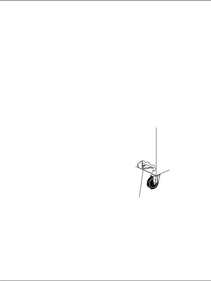
When steamers are mounted on casters, you must use a connector that complies with the Standard for Connectors of Movable Gas Appliances, ANSI-Z21.69 (latest edition), and a quick-disconnect device that complies with the Standard for Quick-Disconnect Devices for Use With Gas Fuel, ANSI-Z21.41 (latest edition).
Provide a gas line strain relief to limit movement of the steamer without depending on the connector and/or any quick-disconnect device or its associated piping to limit movement of the steamer. Attach the gas line strain relief to the rear of the steamer (Fig. 1).
1/2 IN. DIA. HOLE PROVIDED FOR
STRAIN RELIEF |
PL-51218 |
|
Should it be necessary to disconnect the restraint, turn off the gas supply before disconnection. Reconnect the restraint before turning the gas supply on and returning the steamer to its installation position.
INSTALLATION CODES AND STANDARDS
Your Vulcan steamer must be installed in accordance with:
6

In the United States:
1.State and local codes.
2.National Fuel Gas Code, ANSI-Z233.1 (latest edition). Copies may be obtained from The American Gas Assoc., Inc., 1515 Wilson Blvd., Arlington, VA 22209.
3.National Electrical Code, ANSI/NFPA No. 70 (latest edition). Copies may be obtained from The National Fire Protection Assoc., Batterymarch Park, Quincy, MA 02269.
In Canada:
1.Local codes.
2.CAN/CGA-B149.1 Installation for Natural Gas Burning Appliances and Equipment (latest edition).
3.CAN/CGA-B149.2 Installation for Propane Burning Appliances and Equipment (latest edition). Copies may be obtained from The Canadian Gas Assoc., 55 Scarsdale Road, Don Mills, Ontario, Canada M3B 2R3.
4.The Canadian Electrical Code, Part 1, C22.1 (latest edition). Copies may be obtained from the Canadian Standards Assoc., 178 Rexdale Blvd., Rexdale, Ontario, Canada M9W 1R3.
LEVELING AND ANCHORING
Using a spirit level, adjust the feet to level the steamer left-to-right and front-to-back. Steamers should be elevated in the front just enough (about 1/16" to 1/8") to give proper drainage. To do this, rotate rear leg adjusting nut by 1 to 11⁄2 turns clockwise after leveling. (Check by pouring a little water in the compartment; all the water should drain.)
The rear feet have holes in the flanges for anchor bolts. DIRECT STEAM COOKERS (STEAMERS WITHOUT GENERATORS) MUST BE ANCHORED TO THE FLOOR.
SERVICE CONNECTIONS (See Fig’s. 2-12)
STEAM CONNECTIONS
Provide dry steam to the inlets. If the steam is heavy with condensate, install a ball float trap before the pressure regulator valve. To ensure rapid heat-up of heavy cold loads, the steam supply line must be sized to maintain pressure and flow as follows:
Direct Connected Steamers (Fig’s. 2-4)
Supply steam at a pressure of 10-12 psi and at a minimum flow rate of 50 lb. per hour per compartment. A pressure reducing valve is furnished and set at 10 psig. Additional steam kettles and kettle modules can be interconnected to the steamer. Consult Vulcan-Hart for recommendations.
Regenerating (Steam Coil) Generators (Fig’s. 5 & 6)
The steam supply to the steam coils must be 15 psi at a minimum flow rate of 125 lb. per hour to the coil.
GAS CONNECTIONS (Fig’s. 7, 8 & 9)
All gas supply connections and any pipe joint compound used must be resistant to the action of propane gases.
Connect gas supply to the gas cabinet base generator using 3⁄4” pipe. Make sure the pipes are clean and free of obstructions.
Codes require that a gas shutoff valve be installed in the gas line ahead of the steam generator.
This gas cabinet base generator is equipped with fixed orifices for use with natural or propane gas and no adjustment is necessary.
The gas line must be capable of delivering gas to the generator without excessive pressure drop at the rate specified on the rating plate. The generator is equipped with a factory preset pressure regulator. Natural gas pressure regulators are preset for 3.5" W.C. (Water Column) for natural gas. Propane gas pressure regulators are preset for 10" W.C. No further adjustment should be required.
WARNING: PRIOR TO LIGHTING, CHECK ALL JOINTS IN THE GAS SUPPLY LINE FOR LEAKS. USE SOAP AND WATER SOLUTION. DO NOT USE AN OPEN FLAME.
After piping has been checked for leaks, all piping receiving gas should be fully purged to remove air.
7

Testing The Gas Supply System
When test pressures exceed 1⁄2 psig (3.45 kPa), the generator and its individual shutoff valve must be disconnected from the gas supply piping system.
When test pressures are 1⁄2 psig (3.45 kPa) or less, the generator must be isolated from the gas supply system by closing its individual manual shutoff valve.
ELECTRICAL CONNECTIONS (Fig’s. 2-12)
WARNING: ELECTRICAL AND GROUNDING CONNECTIONS MUST COMPLY WITH THE APPLICABLE PORTIONS OF THE NATIONAL ELECTRICAL CODE ANSI/NFPA-70 (LATEST EDITION) AND/OR OTHER LOCAL ELECTRICAL CODES.
WARNING: DISCONNECT ELECTRICAL POWER SUPPLY AND PLACE A TAG AT THE DISCONNECT SWITCH TO INDICATE THAT YOU ARE WORKING ON THE CIRCUIT.
Do not connect the steamer to electrical supply until after gas connections (if applicable) have been made.
All Models
Unless otherwise specified, field wire electrical connection is to be 120 volts, 60 Hertz, single phase, with grounding wire. Connect electrical supply to the pigtail leads in the supply junction box located next to the boiler control box for electric generators in a 24" wide base, and under the boiler control box for all other generator bases. The supply junction box is located on the underside of the cabinet top on direct steam models. Use copper wire suitable for at least 75°C temperature. A grounding wire must be connected to the ground lug in the junction box.
When optional step down transformer is used on electrically heated generators, the 120 volt connection is not required.
Electrically Heated Generators
Make the electrical supply connection in the junction box on the contactor box. The supply wiring and circuit protection must be adequate for the kilowatt load drawn by the cooker. A grounding wire must be connected to the ground lug in the junction box. Use copper wire of the size and temperature rating marked on the supply label.
DRAIN CONNECTIONS (Fig’s. 2-12)
Drain connections must be the open air gap type. Provide a suitable drain under the drain pipes. For proper drainage, a floor sink with minimum of 12" depth is recommended.
CAUTION: In order to avoid any back pressure in the steamer, do not connect solidly to any drain connection.
PLUMBING CONNECTIONS (Fig’s. 2-12)
WARNING: PLUMBING CONNECTIONS MUST COMPLY WITH APPLICABLE SANITARY, SAFETY AND PLUMBING CODES.
Before connecting the steamer to water, the water supply should be analyzed to make sure hardness is less than 2.0 grains per gallon and pH of 7.5. The water supply should be clear with no sediment or suspended material present. If the water supply fails to meet these standards, it will be necessary to install a water conditioner on the boiler water feed. APPLIANCE FAILURE CAUSED BY INADEQUATE WATER QUALITY IS NOT COVERED UNDER WARRANTY.
The use of strainers or filters will not remove minerals from the water.
Cold Water
Used as boiler fill water and cold water condenser on boiler blowdown line. Connect a cold water line to the 1⁄4” N.P.T. cold water condensor line. Twenty (20) psig minimum water pressure is required at the connections.
VENT HOOD
Information on the construction and installation of ventilating hoods may be obtained from the standard for “Vapor Removal from Cooking Equipment,” NFPA No. 96 (latest edition).
8

SERVICE CONNECTIONS
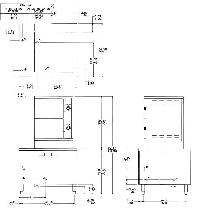
DIRECT STEAM, VSX24D
LEGEND
A.COLD SUPPLY WATER CONNECTION: 1⁄4” TUBING FOR COLD WATER CONDENSER SUPPLY, AND BOILER FEED.
B.STEAM SUPPLY CONNECTION: 3⁄4” NPT FOR STEAM COOKING (A STEAM PRESSURE REDUCING VALVE IS MOUNTED AS STANDARD AND SET FOR 10 PSI MAXIMUM INPUT TO UNIT).
C.ELECTRICAL CONNECTION FOR CONTROLS: 120V/60HZ/1PH/300 WATT MAXIMUM, POWER SUPPLY WITH GROUNDING WIRE REQUIRED. (FOR OTHER THAN 120 VOLT SUPPLY CONSULT FACTORY FOR LOCATION OF THIS CONNECTION.)
D.DRAIN: COPPER TUBE COMPARTMENT & EXHAUST GROUP APPROXIMATELY 2" IN DIAMETER. (PROVIDE AN OPEN AIR GAP TYPE DRAIN DIRECTLY UNDER THE UNIT FRAME. DO NOT CONNECT SOLIDLY TO ANY DRAIN CONNECTION.)
A
INCHES.
9

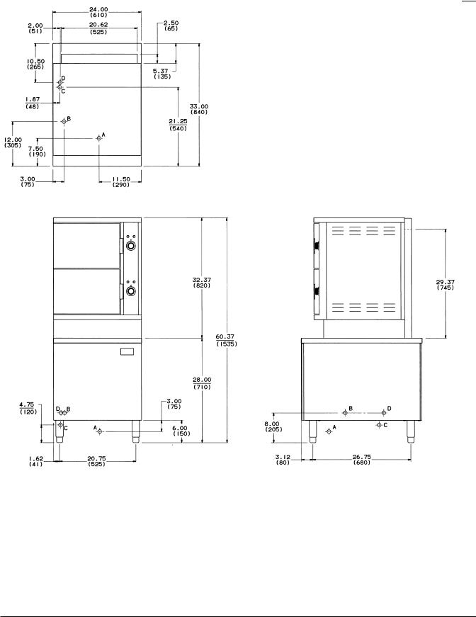
SERVICE CONNECTIONS
DIRECT STEAM, VSX36D
LEGEND
A.COLD SUPPLY WATER CONNECTION: 1⁄4” TUBING FOR COLD WATER CONDENSER, AND BOILER FEED.
B.STEAM SUPPLY CONNECTION: 3⁄4” NPT FOR STEAM COOKING. (A STEAM PRESSURE REDUCING VALVE IS MOUNTED AS STANDARD AND SET FOR 10 PSI MAXIMUM INPUT TO UNIT.)
C.ELECTRICAL CONNECTION FOR CONTROLS: 120V/60HZ/1PH/300 WATT MAXIMUM, POWER SUPPLY WITH GROUNDING WIRE REQUIRED. (FOR OTHER THAN 120 VOLT SUPPLY CONSULT FACTORY FOR LOCATION OF THIS CONNECTION.)
D.DRAIN: COPPER TUBE COMPARTMENT & EXHAUST GROUP APPROXIMATELY 2" DIAMETER. (PROVIDE AN OPEN AIR GAP TYPE DRAIN DIRECTLY UNDER UNIT FRAME. DO NOT CONNECT SOLIDLY TO ANY DRAIN CONNECTION.)
NOTE: DIMENSIONS WHICH LOCATE THE ABOVE CONNECTIONS HAVE A
INCHES.
10
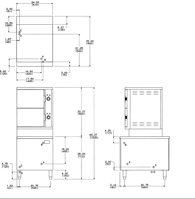
SERVICE CONNECTIONS
DIRECT STEAM, VSX42DT
LEGEND
A.COLD SUPPLY WATER CONNECTION: 1⁄4” TUBING FOR COLD WATER CONDENSER, AND BOILER FEED.
B.STEAM SUPPLY CONNECTION: 3⁄4” NPT FOR STEAM COOKING. (A STEAM PRESSURE REDUCING VALVE IS MOUNTED AS STANDARD AND SET FOR 10 PSI MAXIMUM INPUT TO UNIT.)
C.ELECTRICAL CONNECTION FOR CONTROLS: 120V/60HZ/1PH/300 WATT MAXIMUM, POWER SUPPLY WITH GROUNDING WIRE REQUIRED. (FOR OTHER THAN 120 VOLT SUPPLY CONSULT FACTORY FOR LOCATION OF THIS CONNECTION.)
D.DRAIN: COPPER TUBE COMPARTMENT & EXHAUST GROUP APPROXIMATELY 2" DIAMETER. (PROVIDE AN OPEN AIR GAP TYPE DRAIN DIRECTLY UNDER UNIT FRAME. DO NOT CONNECT SOLIDLY TO ANY DRAIN CONNECTION.)
NOTE: DIMENSIONS WHICH LOCATE THE ABOVE CONNECTIONS HAVE A
± ±
11

SERVICE CONNECTIONS |
|
REGENERATING STEAM, VSX36R |
FIG. 5 |
|
LEGEND |
A.STEAM SUPPLY CONNECTION: 3⁄4” NPT FOR STEAM INLET TO BOILER. (A STEAM PRESSURE REDUCING VALVE IS SHIPPED WITH THE UNIT AND MUST BE FIELD INSTALLED AND ADJUSTED FOR 15 PSI MAXIMUM TO THE UNIT.)
B.ELECTRICAL CONNECTION FOR CONTROLS: 120V/60HZ/1PH/300 WATT MAXIMUM, POWER SUPPLY WITH GROUNDING WIRE REQUIRED. (FOR OTHER THAN 120 VOLT SUPPLY CONSULT FACTORY FOR LOCATION OF THIS CONNECTION.)
C.DRAIN: COMPARTMENT, BOILER AND EXHAUST GROUP APPROXIMATELY 2" IN DIAMETER. (PROVIDE AN OPEN AIR GAP TYPE DRAIN DIRECTLY UNDER UNIT FRAME. DO NOT CONNECT SOLIDLY TO ANY DRAIN CONNECTION.)
D.COLD SUPPLY WATER CONNECTION: 1⁄4” NPT FOR BOILER DRAIN & COMPARTMENT DRAIN COLD WATER CONDENSERS, AND BOILER FEED.
A
12

SERVICE CONNECTIONS |
|
REGENERATING STEAM, VSX42RT |
FIG. 6 |
|
LEGEND |
A.STEAM SUPPLY CONNECTION: 3⁄4” NPT FOR STEAM INLET TO BOILER. (A STEAM PRESSURE REDUCING VALVE IS SHIPPED WITH THE UNIT AND MUST BE FIELD INSTALLED AND ADJUSTED FOR 15 PSI MAXIMUM TO THE UNIT.)
B.ELECTRICAL CONNECTION FOR CONTROLS: 120V/60HZ/1PH/300 WATT MAXIMUM, POWER SUPPLY WITH GROUNDING WIRE REQUIRED. (FOR OTHER THAN 120 VOLT SUPPLY CONSULT FACTORY FOR LOCATION OF THIS CONNECTION.)
C.DRAIN: COMPARTMENT, BOILER AND EXHAUST GROUP APPROXIMATELY 2" IN DIAMETER. (PROVIDE AN OPEN AIR GAP TYPE DRAIN DIRECTLY UNDER UNIT FRAME. DO NOT CONNECT SOLIDLY TO ANY DRAIN CONNECTION.)
D.COLD SUPPLY WATER CONNECTION: 1⁄4” NPT FOR BOILER DRAIN & COMPARTMENT DRAIN COLD WATER CONDENSERS, AND BOILER FEED.
CONNECTIONS HAVE A
IN INCHES. DIMENSIONS
13
SERVICE CONNECTIONS GAS HEAT, VSX24G
14
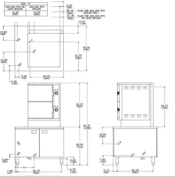
SERVICE CONNECTIONS |
|
GAS HEAT, VSX36G |
FIG. 8 |
|
LEGEND |
A. |
GAS CONNECTION: 3⁄4” NPT. |
B. ELECTRICAL CONNECTION FOR CONTROLS: 120V/60HZ/1PH/300 WATT |
|
|
MAXIMUM, POWER SUPPLY WITH GROUNDING WIRE REQUIRED. (FOR |
|
OTHER THAN 120 VOLT SUPPLY CONSULT FACTORY FOR LOCATION OF |
|
THIS CONNECTION.) |
C. |
DRAIN: COMPARTMENT, BOILER AND EXHAUST GROUP APPROXIMATELY |
|
31⁄2” IN DIAMETER. (PROVIDE AN OPEN AIR GAP TYPE DRAIN DIRECTLY |
UNDER UNIT FRAME. DO NOT CONNECT SOLIDLY TO ANY DRAIN
CONNECTION.)
D. COLD SUPPLY WATER CONNECTION: 1⁄4” NPT FOR BOILER DRAIN &
COMPARTMENT DRAIN COLD WATER CONDENSERS, AND BOILER FEED.
NOTE: DIMENSIONS WHICH LOCATE THE ABOVE CONNECTIONS HAVE A
TOLERANCE OF ± 3 IN. (± 75 MM). NORMAL DIMENSIONS ARE IN INCHES.
DIMENSIONS IN ( ) ARE IN MILLIMETERS.
EQUIPMENT CLEARANCES
TO COMBUSTIBLE CONSTRUCTION
REAR: 6 IN. MIN. (150 MM.)
LEFT SIDE: 6 IN. MIN. (150 MM.)
RIGHT SIDE: 6 IN. MIN. (150 MM.)
15

SERVICE CONNECTIONS |
|
GAS HEAT, VSX42GT |
FIG. 9 |
|
LEGEND |
A. |
GAS CONNECTION: 3⁄4” NPT. |
B. ELECTRICAL CONNECTION FOR CONTROLS: 120V/60HZ/1PH/300 WATT |
|
|
MAXIMUM, POWER SUPPLY WITH GROUNDING WIRE REQUIRED. (FOR |
|
OTHER THAN 120 VOLT SUPPLY CONSULT FACTORY FOR LOCATION OF |
|
THIS CONNECTION.) |
C. |
DRAIN: COMPARTMENT, BOILER AND EXHAUST GROUP APPROXIMATELY |
|
31⁄2” IN DIAMETER. (PROVIDE AN OPEN AIR GAP TYPE DRAIN DIRECTLY |
|
UNDER UNIT FRAME. DO NOT CONNECT SOLIDLY TO ANY DRAIN |
CONNECTION.)
D. COLD SUPPLY WATER CONNECTION: 1⁄4” NPT FOR BOILER DRAIN &
COMPARTMENT DRAIN COLD WATER CONDENSERS, AND BOILER FEED.
NOTE: DIMENSIONS WHICH LOCATE THE ABOVE CONNECTIONS HAVE A
TOLERANCE OF ± 3 IN. (± 75 MM). NORMAL DIMENSIONS ARE IN INCHES.
16
SERVICE CONNECTIONS |
|
ELECTRIC HEAT, VSX24E |
FIG. 10 |
|
LEGEND |
A. |
JUNCTION BOX: J.I.C. 6X6X4 FOR ELECTRICAL SUPPLY CONNECTION FOR |
|
HEAT. |
B. ELECTRICAL CONNECTION FOR CONTROLS: 120V/60HZ/1PH/300 WATT |
|
|
MAXIMUM, POWER SUPPLY WITH GROUNDING WIRE REQUIRED. (NOT |
|
PROVIDED IF A STEP DOWN TRANSFORMER IS FURNISHED.) |
C. COLD SUPPLY WATER CONNECTION: 1⁄4” NPT FOR BOILER DRAIN AND |
|
|
COMPARTMENT DRAIN COLD WATER CONDENSERS. |
D. |
DRAIN: COMPARTMENT, BOILER AND EXHAUST GROUP APPROXIMATELY |
|
31⁄2” IN DIAMETER. (PROVIDE AN OPEN AIR GAP TYPE DRAIN DIRECTLY |
|
UNDER UNIT FRAME. DO NOT CONNECT SOLIDLY TO ANY DRAIN |
|
CONNECTION.) |
A
.
17
SERVICE CONNECTIONS |
|
ELECTRIC HEAT, VSX36E |
FIG. 11 |
|
LEGEND |
A. |
JUNCTION BOX: J.I.C. 6X6X4 FOR ELECTRICAL SUPPLY CONNECTION FOR |
|
HEAT. |
B. ELECTRICAL CONNECTION FOR CONTROLS: 120V/60HZ/1PH/300 WATT |
|
|
MAXIMUM, POWER SUPPLY WITH GROUNDING WIRE REQUIRED. (NOT |
|
PROVIDED IF A STEP DOWN TRANSFORMER IS FURNISHED.) |
C. COLD SUPPLY WATER CONNECTION: 1⁄4” NPT FOR BOILER DRAIN AND |
|
|
COMPARTMENT DRAIN COLD WATER CONDENSERS. |
D. |
DRAIN: COMPARTMENT, BOILER AND EXHAUST GROUP APPROXIMATELY |
|
31⁄2” IN DIAMETER. (PROVIDE AN OPEN AIR GAP TYPE DRAIN DIRECTLY |
|
UNDER UNIT FRAME. DO NOT CONNECT SOLIDLY TO ANY DRAIN |
|
CONNECTION.) |
NOTE: DIMENSIONS WHICH LOCATE THE ABOVE CONNECTIONS HAVE A
TOLERANCE OF ± 3 IN. (± 75 MM). NORMAL DIMENSIONS ARE IN INCHES.
DIMENSIONS IN ( ) ARE IN MILLIMETERS.
EQUIPMENT CLEARANCES
TO COMBUSTIBLE CONSTRUCTION
REAR: 2 IN. MIN. (50 MM.)
18

SERVICE CONNECTIONS |
|
ELECTRIC HEAT, VSX42ET |
FIG. 12 |
|
LEGEND |
A. |
JUNCTION BOX: J.I.C. 6X6X4 FOR ELECTRICAL SUPPLY CONNECTION FOR |
|
HEAT. |
B. ELECTRICAL CONNECTION FOR CONTROLS: 120V/60HZ/1PH/300 WATT |
|
|
MAXIMUM, POWER SUPPLY WITH GROUNDING WIRE REQUIRED. (NOT |
|
PROVIDED IF A STEP DOWN TRANSFORMER IS FURNISHED.) |
C. COLD SUPPLY WATER CONNECTION: 1⁄4” NPT FOR BOILER DRAIN AND |
|
|
COMPARTMENT DRAIN COLD WATER CONDENSERS. |
D. |
DRAIN: COMPARTMENT, BOILER AND EXHAUST GROUP APPROXIMATELY |
|
31⁄2” IN DIAMETER. (PROVIDE AN OPEN AIR GAP TYPE DRAIN DIRECTLY |
|
UNDER UNIT FRAME. DO NOT CONNECT SOLIDLY TO ANY DRAIN |
|
CONNECTION.) |
A
.
19

START-UP TEST RUN
After the appliance is installed and proper service connections have been made, thoroughly test the steam cooker before operation.
Gas Powered Steam Generator
1.Open manual gas shutoff valve, and if the appliance has a manual blowdown valve, close it. Open left cabinet door and turn water fill and power switch ON. The red light will come on and water will fill boiler to the required level in about 15 minutes. Observe water level gauge glass to verify. Both valves on gauge glass assembly must be open.
2.The dial on the gas combination control valve has three positions (On-Pilot-Off) for manual gas control of main burners and pilot. Turn dial on gas combination valve to PILOT. Depress dial and light pilot burner; maintain dial in depressed position for about 30 seconds and release. Observe that pilot burner flame stays on. If the flame should go out, wait 5 minutes before relighting.
3.Turn gas combination control valve dial to ON and burners will ignite. Steam generation will begin and be completed in about 15 minutes. Observe that the boiler pressure gauge indicates steam pressure in the range of 9-12 psi (9-13 psi if a kettle is connected to the steamer).
4.Set both timer knobs to “0”. Open both compartment doors and observe that no steam has entered the cooking compartments. Close doors.
5.Set both timer knobs to 2 minutes. The READY lights will go off, the COOKING lights will come on, and steam will be heard entering the compartments.
After one minute, open each door and observe that steam has ceased to enter each compartment, but COOKING lights and cooking times at “01” are maintained.
WARNING: THE COOKING COMPARTMENTS CONTAIN LIVE STEAM. STAY CLEAR WHILE OPENING EACH DOOR.
7.Close doors. Steam generation and cook times will resume. Observe appliance drain that live steam from compartments is being cooled by cold water from the cold water solenoid valve.
8.When timer knobs are on “0”, each buzzer will sound, steam generation will cease, COOKING lights will go off and READY lights will come on. To silence buzzers, turn timer knobs to OFF position.
9.During simulation of cooking cycle, burners will cycle on and off to maintain steam pressure in boiler.
10.Turn power switch OFF. Amber light will go out.
11.Blow down boiler (see BLOW DOWN BOILER in this manual).
Electrically Powered Steam Generator
1.If steamer has a manual blowdown valve, close it. Open left cabinet door and turn power switch ON. Water will fill boiler to the required level in about 15 minutes. Observe water level gauge glass to verify. Both valves on gauge glass assembly must be open. Steam generation will begin and be completed in about 15 minutes.
2.Set both timer knobs to “0”. Open both compartment doors and observe that no steam has entered the cooking compartments. Close doors.
3.Set both timer knobs to 2 minutes. READY lights will go off, COOKING lights will come on, and steam will be heard entering the compartments.
After one minute, open each door and observe that steam has ceased to enter each compartment, but COOKING lights and cooking times at “01” are maintained.
WARNING: THE COOKING COMPARTMENTS CONTAIN LIVE STEAM. STAY CLEAR WHILE OPENING EACH DOOR.
4.Close doors. Steam generation and cook times will resume. Observe appliance drain that live steam from compartments is being cooled by cold water from the cold water solenoid valve.
5.When timer knobs are on “0”, each buzzer will sound, steam generation will cease, COOKING lights will go off and READY lights will come on. To silence buzzers, turn timer knobs to OFF position.
6.During simulation of cooking cycle, the heating elements will cycle on and off to maintain steam pressure in the boiler.
20
7.Turn power switch OFF. Amber light will go out.
8.Blow down boiler (see BLOW DOWN BOILER in this manual).
Direct Steam Powered Cooker
1.Set both timer knobs to “0”. Open both compartment doors and observe that no steam has entered cooking compartments. Close doors.
2.Set both timer knobs to 2 minutes. READY lights will go off, COOKING lights will come on, and steam will be heard entering the compartments.
After one minute, open each door and observe that steam has ceased to enter each compartment, but COOKING lights and cooking times at “01” are maintained.
WARNING: THE COOKING COMPARTMENTS CONTAIN LIVE STEAM. STAY CLEAR WHILE OPENING EACH DOOR.
3.Close doors. Steam generation and cook times will resume. Observe appliance drain that live steam from compartments is being cooled by cold water from the cold water solenoid valve.
4.When timer knobs are on “0”, each buzzer will sound, steam generation will cease, COOKING lights will go off and READY lights will come on. To silence buzzers, turn timer knobs to OFF position.
Regenerative Steam Powered Generator
1.If the steamer has a manual blowdown valve, close it. Turn power switch ON. Water will fill the boiler to the required level in about 15 minutes. Observe water level gauge glass to verify. Both valves on gauge glass assembly must be open. Steam generation will begin and be completed in about 15 minutes.
2.Set both timer knobs to “0”. Open both compartment doors and observe that no steam has entered the cooking compartments. Close doors.
3.Set both timer knobs to 2 minutes. READY lights will go off, COOKING lights will come on, and steam will be heard entering the compartments.
After one minute, open each door and observe that steam has ceased to enter each compartment, but COOKING lights and cooking times at “01” are maintained.
WARNING: THE COOKING COMPARTMENTS CONTAIN LIVE STEAM. STAY CLEAR WHILE OPENING EACH DOOR.
4.Close doors. Steam generation and cook times will resume. Observe appliance drain that live steam from compartments is being cooled by cold water from the cold water solenoid valve.
5.When timer knobs are on “0”, each buzzer will sound, steam generation will cease, COOKING lights will go off and READY lights will come on. To silence buzzers, turn timer knobs to OFF position.
6.During simulation of cooking cycle, steam coils will cycle on and off to maintain steam pressure in the boiler.
7.Turn power switch OFF. Amber light will go out.
8.Blow down boiler (see BLOW DOWN BOILER in this manual).
BLOW DOWN BOILER
Always blow down boiler when boiler is under maximum pressure and no steam is being used.
Automatic Blowdown
Turn power switch OFF. Depress blowdown button. Blowdown timer will operate for 4 minutes. At end of blowdown, turn fill switch to ON and allow boiler to fill.
Manual Blowdown
Turn power switch OFF. Open blowdown valve. After boiler has drained completely, close blowdown valve and turn fill switch to ON and allow boiler to fill.
21

OPERATION
WARNING: THE STEAMER AND ITS PARTS ARE HOT. USE CARE WHEN OPERATING, CLEANING OR SERVICING THE STEAMER. THE COOKING COMPARTMENTS CONTAIN LIVE STEAM. STAY CLEAR WHILE OPENING EACH DOOR.
CONTROLS — CABINET BASE GENERATOR (Fig. 13)
Handhole Cover Assembly — when unbolted and removed, allows internal examination and cleaning of boiler if required.
Water Level Gauge Assembly — permits visual confirmation that water level is being maintained in the boiler during operation. The correct water level is a point one-half of the height of the glass. The manual valves at the top and bottom of this assembly must be fully open, and only closed if the glass tube should be damaged.
Observe that the water is clean and clear in the glass tube. The appearance of extreme murkiness in the water indicates inadequate water quality and will cause failure of controls and the steamer. Warranty does not cover malfunction due to poor water conditions. Blow down and/or clean the generator.
Pilot Burner (Gas Base Generator Only) — should remain lit at all times unless the steamer will not be in use for an extended period of time. If at any time the flame goes out, wait 5 minutes before relighting.
Main Burners (Gas Base Generator Only) — cycle on and off to maintain steam pressure in the boiler.
Gas Combination Control Valve (Gas Base Generator Only) — regulates flow of gas to burners.
Low Water Cutoff/Automatic Fill Control — Level Sensing Probes — these controls allow the feed water to enter the generator when the water level is low. They will also shut off the heat source to the boiler if the water level drops too low. The level sensing probes may be easily removed to inspect for lime build-up. As a rule, the condition of these devices will indicate the overall water condition of the boiler. Clean the probes if needed. Controls may not function and serious clogging will occur if a daily blowdown procedure is not followed.
Drain Solenoid Valve — a quick acting drain valve provided for daily blowdown of the generator.
Strainers — a strainer is used in the water inlet line to prevent foreign matter from becoming lodged in the inlet solenoid valve. A “Y” strainer is inserted upstream of the drain solenoid valve to allow the valve to operate smoothly. A strainer is used in the pressure regulating valve on models using direct steam supply.
Boiler Fill Solenoid Valve — admits water to the boiler when demanded by the automatic fill controls in order to maintain the correct water level in the steam generator.
Blowdown Drain CWC Solenoid Valve — allows cold water to flow to boiler blowdown drain and helps cool the boiler water prior to its discharge into the drain.
Cycling Pressure Switch — controls boiler pressure between prescribed limits by turning the heat source on and off. A back-up switch of identical design is provided and has a higher high setting and a lower low setting than the primary control.
Power Switch — when turned ON will automatically begin the steam generating process in the boiler. The power switch is fastened to the front face of the generator control box.
Pressure Regulating Valve — used to control manifold steam pressure at 10-12 psi on models using direct steam supply.
Water Inlet Ball Valve — water service valve which can be used to stop water flow to the steamer when the steamer is being serviced.
High Limit Thermostat — a protective device which shuts off the gas or electric power if the boiler overheats.
Descaler — hangs submerged in water inside the generator and helps control scaling.
Drain — drains steam condensate and water from cooking compartments and boiler.
22
 Loading...