

Page 1
Owner's Manual
XC70
WEB EDITION
Page 2

Page 3

WELCOME TO THE WORLD-WIDE FAMILY OF VOLVO OWNERS.
We trust that you will enjoy many years of safe
driving in your Volvo, an automobile designed
with your safety and comfort in mind. We encourage you to familiarize yourself with the equipment
descriptions and operating instructions in this
manual.
We also urge you and your passengers to wear
seat belts at all times in this (or any other) vehicle.
And, of course, please do not operate a vehicle if
you may be affected by alcohol, medication or
any impairment that could hinder your ability to
drive.
Your Volvo is designed to meet all applicable federal safety and emission standards. If you have
any questions regarding your vehicle, please contact your Volvo retailer or see the section "Contacting Volvo" in this manual's "Introduction"
chapter for information on getting in touch with
Volvo in the United States and Canada.
Page 4

Contents
2
* Option/accessory, for more information, see Introduction.
00
00 Introduction
Important information................................. 6
Environment.............................................. 12
Important warnings................................... 13
01
01 Safety
Occupant safety........................................ 16
Reporting safety defects........................... 17
Seat belts ................................................. 18
Supplemental Restraint System (SRS) .... 21
Occupant Weight Sensor ......................... 26
Side impact protection (SIPS) airbags ..... 30
Inflatable Curtain (IC) ............................... 32
Whiplash Protection System – WHIPS..... 33
Crash mode.............................................. 35
Child safety............................................... 37
Child restraint systems............................. 40
Infant seats............................................... 42
Convertible seats...................................... 44
Booster cushions...................................... 46
ISOFIX/LATCH lower anchors.................. 47
Top tether anchors.................................... 49
Integrated booster cushion*...................... 50
Child safety locks...................................... 53
02
02 Locks and alarm
Remote key and key blade....................... 56
Private locking ......................................... 65
Keyless drive............................................. 66
Locks........................................................ 69
Alarm......................................................... 72
Page 5
Contents
* Option/accessory, for more information, see Introduction.
3
03
03 Your driving environment
Instruments and controls.......................... 76
Ignition modes.......................................... 86
Seats......................................................... 88
Steering wheel.......................................... 95
Lighting..................................................... 97
Wipers and washers............................... 105
Windows................................................. 108
Mirrors..................................................... 110
Digial compass*...................................... 113
Power moonroof* ................................... 115
HomeLink® Wireless Control System*.... 117
Starting the engine.................................. 120
Transmission........................................... 125
Eco Guide* and Power Meter*................ 129
Brakes..................................................... 131
Parking brake.......................................... 134
Hill Descent Control (HDC)*.................... 137
04
04 Driver support
Stability system....................................... 142
Road sign information (RSI)* .................. 144
Cruise control.......................................... 146
Adaptive Cruise Control (ACC)*.............. 148
Distance Alert* ....................................... 159
City Safety™ .......................................... 162
Collision warning with Full Auto-brake
and Pedestrian Detection*...................... 168
Driver Alert System* ............................... 176
Park assist*............................................. 182
Rear Park Assist Camera (PAC)* ............ 186
Blind Spot Information System (BLIS)*... 190
05
05 Comfort and driving pleasure
Volvo Sensus.......................................... 196
Menus and messages............................. 197
The MY CAR menus............................... 199
Climate system....................................... 205
Trip computer......................................... 215
Active chassis system–Four C*............... 222
Passenger compartment convenience... 223
Page 6
Contents
4
* Option/accessory, for more information, see Introduction.
06
06 Infotainment
Introduction............................................. 230
Radio....................................................... 240
Media player........................................... 249
AUX/USB sockets................................... 254
Bluetooth® media ................................... 257
Bluetooth® hands-free connection ........ 259
Cell phone voice control*........................ 268
07
07 During your trip
Driving recommendations....................... 274
Refueling................................................. 278
Loading................................................... 283
Cargo area ............................................. 289
Towing a trailer....................................... 293
Emergency towing.................................. 296
08
08 Wheels and tires
General information ............................... 302
Tire inflation............................................. 305
Inflation pressure ................................... 307
Tire designations .................................... 308
Glossary of tire terminology ................... 310
Vehicle loading ....................................... 311
Uniform Tire Quality Grading ................. 313
Snow chains, snow tires, studded tires . 314
Temporary Spare ................................... 315
Tire Sealing System*............................... 316
Changing a wheel .................................. 322
Tire Pressure Monitoring System (TPMS) 325
Page 7
Contents
5
09
09 Maintenance and
specifications
Volvo maintenance.................................. 332
Maintaining your car............................... 333
Hood and engine compartment.............. 335
Engine oil................................................ 336
Fluids...................................................... 338
Replacing bulbs...................................... 340
Wiper blades and washer fluid................ 347
Battery..................................................... 350
Fuses...................................................... 354
Vehicle care............................................. 363
10
10 Specifications
Label information.................................... 370
Specifications......................................... 372
Overview of information and warning
symbols................................................... 378
Volvo programs....................................... 381
11
11 Index
Index....................................................... 382
Page 8
Introduction
Important information
6
Contacting Volvo
In the USA:
Volvo Cars of North America, LLC
Customer Care Center
1 Volvo Drive,
P.O. Box 914
Rockleigh, New Jersey 07647
1-800-458-1552
www.volvocars.com/us
In Canada:
Volvo Cars of Canada
National Customer Service
9130 Leslie Street, Suite 101
Richmond Hill, Ontario L4B 0B9
1-800-663-8255
www.volvocars.com/ca
About this manual
•
Before you operate your vehicle for the
first time, please familiarize yourself with
the information found in the chapters
"Your Driving Environment" and "During
Your Trip."
•
Information contained in the balance of
the manual is extremely useful and should
be read after operating the vehicle for the
first time.
•
The manual is structured so that it can be
used for reference. For this reason, it
should be kept in the vehicle for ready
access.
Footnotes
Certain pages of this manual contain information in the form of footnotes at the bottom of
the page. This information supplements the
text that the footnote number refers to (a letter is used if the footnote refers to text in a
table).
Display texts
There are several displays in the driver’s field
of vision that show messages generated by
various systems and functions in the vehicle.
These texts are indicated in the Owner’s
Manual by being in slightly larger type than
the surrounding text and are printed in gray,
(for example:
Change doors unlock
setting).
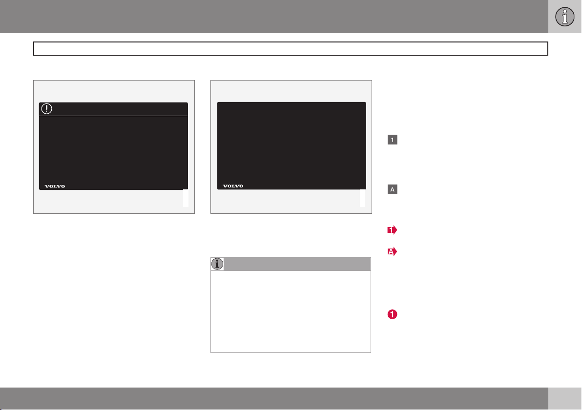
Decals
There are various types of decals in the vehicle whose purpose is to provide important
information in a clear and concise way. The
importance of these decals is explained as
follows, in descending order of importance.
Risk of injury
G031590
Black ISO symbols on a yellow warning background, white text/image on a black background. Decals of this type are used to indicate potential danger. Ignoring a warning of
this type could result in serious injury or
death.
Page 9
Introduction
Important information
7
Risk of damage to the vehicle
G031592
White ISO symbols and white text/image on a
black or blue warning background and space
for a message. If the information on decals of
this type is ignored, damage to the vehicle
could result.
Information
G031593
White ISO symbols and white text/image on a
black background. These decals provide general information.
NOTE
The decals shown in the Owner’s Manual
are examples only and are not intended to
be reproductions of the decals actually
used in the vehicle. The purpose is to give
an indication of how they look and their
approximate location in the vehicle. The
applicable information for your particular
vehicle can be found on the respective
decals in the vehicle.
Types of lists used in the manual
Procedures
Procedures (step-by-step instructions), or
actions that must be carried out in a certain
order, are arranged in numbered lists in this
manual.
If there is a series of illustrations associated with step-by-step instructions, each
step in the procedure is numbered in the
same way as the corresponding illustration.
Lists in which letters are used can be
found with series of illustrations in cases
where the order in which the instructions
are carried out is not important.
Arrows with or without numbers are used
to indicate the direction of a movement.
Arrows containing letters are used to indicate movement.
If there are no illustrations associated with a
step-by-step list, the steps in the procedure
are indicated by ordinary numbers.
Position lists
Red circles containing a number are used
in general overview illustrations in which
certain components are pointed out. The
corresponding number is also used in the
position list's description of the various
components.
Page 10
Introduction
Important information
8
Bullet lists
Bullets are used to differentiate a number of
components/functions/points of information
that can be listed in random order.
For example:
•
Coolant
•
Engine oil
Continued
} }This symbol can be found at the lower
right corner of an odd-numbered (right-hand)
page to indicate that the current topic is continued on the following page.
Options and accessories
Optional or accessory equipment described
in this manual is indicated by an asterisk.
Optional or accessory equipment may not be
available in all countries or markets. Please
note that some vehicles may be equipped differently, depending on special legal requirements.
Contact your Volvo retailer for additional
information.
NOTE
•
All information, illustrations and specifications contained in this manual are
based on the latest product information available at the time of publication.
•
Volvo reserves the right to make model
changes at any time, or to change
specifications or design without notice
and without incurring obligation.
•
Do not export your Volvo to another
country before investigating that country's applicable safety and emission
control requirements. In some cases it
may be difficult or impossible to comply with these requirements. Modifications to the emission control system(s)
may render your Volvo not certifiable
for legal operation in the U.S., Canada
and other countries.
WARNING
If your vehicle is involved in an accident,
unseen damage may affect its drivability
and safety.
WARNING
CALIFORNIA proposition 65
Engine exhaust, some of its constituents,
and certain vehicle components contain or
emit chemicals known to the state of California to cause cancer, and birth defects
or other reproductive harm. In addition,
certain fluids contained in vehicles and
certain products of component wear contain or emit chemicals known to the State
of California to cause cancer, and birth
defects or other reproductive harm.
WARNING
Certain components of this vehicle such as
air bag modules, seat belt pretensioners,
adaptive steering columns, and button cell
batteries may contain Perchlorate material.
Special handling may apply for service or
vehicle end of life disposal.
See www.dtsc.ca.gov/hazardouswaste/
perchlorate.
Page 11
Introduction
Important information
9
Shiftlock
When your vehicle is parked, the gear selector is locked in the P (Park) position. To
release the selector from this position, the
ignition must be in mode II (see page 86) or
the engine must be running. Depress the
brake pedal, press the button on the front
side of the gear selector and move the selector from P (Park).
Anti-lock Brake System (ABS)
The ABS system performs a brief self-diagnostic test when the engine has been started
and driver releases the brake pedal. Another
automatic test may be performed when the
vehicle first reaches a speed of approximately
6 mph (10 km/h). The brake pedal will pulsate
several times and a sound may be audible
from the ABS control module. This is normal.
Fuel filler door
Press the button on the light switch panel
(see the illustration on page 280) when the
vehicle is at a standstill to unlock the fuel filler
door. It will relock when closed and there will
be an audible click.
Points to keep in mind
•
Do not export your Volvo to another
country before investigating that country's applicable safety and exhaust emission requirements. In some cases it may
be difficult or impossible to comply with
these requirements. Modifications to the
emission control system(s) may render
your Volvo not certifiable for legal operation in the U.S., Canada and other countries.
•
All information, illustrations and specifications contained in this manual are based
on the latest product information available at the time of publication. Please note
that some vehicles may be equipped differently, depending on special legal
requirements. Optional equipment described in this manual may not be available in
all markets.
•
Some of the illustrations shown are
generic and may not depict the exact
model for which this manual is intended.
•
Volvo reserves the right to make model
changes at any time, or to change specifications or design without notice and
without incurring obligation.
Crash event data
This vehicle is equipped with an event data
recorder (EDR). The main purpose of an EDR
is to record, in certain crash or near crash-like
situations, such as an air bag deployment or
hitting a road obstacle, data that will assist in
understanding how a vehicle's systems performed. The EDR is designed to record data
related to vehicle dynamics and safety sys-
tems for a short period of time, typically 30
seconds or less. The EDR in this vehicle is
designed to record such data as:
•
How various systems in your vehicle were
operating;
•
Whether or not the driver and passenger
safety belts were buckled/fastened;
•
How far (if at all) the driver was depressing the accelerator and/or brake pedal;
and,
•
How fast the vehicle was traveling.
These data can help provide a better understanding of the circumstances in which
crashes and injuries occur.
NOTE
EDR data are recorded by your vehicle
only if a non-trivial crash situation occurs;
no data are recorded by the EDR under
normal driving conditions and no personal
data (e.g., name, gender, age, and crash
location) are recorded. However, other
parties, such as law enforcement, could
combine the EDR data with the type of
personally identifying data routinely
acquired during a crash investigation.
To read data recorded by an EDR, special
equipment is required, and access to the
vehicle or the EDR is needed. In addition to
Page 12

Introduction
Important information
10
the vehicle manufacturer, other parties, such
as law enforcement, that have the special
equipment, can read the information if they
have access to the vehicle or the EDR.
Furthermore, your vehicle is equipped with a
number of computers whose task is to continuously control and monitor the vehicle’s
operation. They can also register information
during normal driving conditions if they detect
a fault relating to the vehicle’s operation and
functionality. Some of the stored information
is required by technicians when carrying out
service and maintenance to enable them to
diagnose and rectify any faults that have
occurred in the vehicle and to enable Volvo to
fulfill legal and other regulatory requirements.
This information may be stored in the vehicle’s computers for a certain period of time.
Volvo will not contribute to spreading the
above-mentioned information to third parties
without the consent of the vehicle’s owner.
However, due to national legal requirements
and regulations, Volvo may be compelled to
provide information of this type to authorities
such as law enforcement agencies or others
who may assert a legal right to obtain such
information.
Volvo and service and repair facilities with
agreements with Volvo have access to the
special technical equipment required in order
to read and interpret the information stored
by the vehicle’s computers. Volvo is responsible for ensuring that the information transmitted to Volvo during service and maintenance
is stored and handled in a secure manner and
that this handling is done in accordance with
applicable legal requirements. For additional
information, contact:
For additional information, contact:
In the United States
Volvo Cars of North America, LLC
Customer Care Center
1 Volvo Drive, P.O. box 914
Rockleigh, New Jersey 07647
1-800-458-1552
www.volvocars.com/us
In Canada
Volvo Cars of Canada
National Customer Service
9130 Leslie Street
Richmond Hill, Ontario L4B 0B9
1-800-663-8255
www.volvocars.com/ca
Volvo Structural Parts Statement
Volvo has always been and continues to be a
leader in automotive safety. Volvo engineers
and manufactures vehicles designed to help
protect vehicle occupants in the event of a
collision.
Volvos are designed to absorb the impact of
a collision. This energy absorption system
including, but not limited to, structural components such as bumper reinforcement bars,
bumper energy absorbers, frames, rails,
fender aprons, A-pillars, B-pillars and body
panels must work together to maintain cabin
integrity and protect the vehicle occupants.
The supplemental restraint system including
but not limited to air bags, side curtain air
bags, and deployment sensors work together
with the above components to provide proper
timing for air bag deployment.
Due to the above, Volvo Cars of North America does not support the use of aftermarket,
alternative or anything other than original
Volvo parts for collision repair.
In addition Volvo does not support the use or
re-use of structural components from an
existing vehicle that has been previously
damaged. Although these parts may appear
equivalent, it is difficult to tell if the parts have
been previously replaced with non-OE parts
or if the part has been damaged as a result of
Page 13
Introduction
Important information
11
a prior collision. The quality of these used
parts may also have been affected due to
environmental exposure.
Information on the Internet
Additional information about your vehicle is
available at www.volvocars.com.
In order to read a QR code, a QR reader is
necessary, which is available as an app for a
number of different cell phones and can be
downloaded from the App Store or Google
Play.
QR code
Open Source Software Notice
This product uses certain free / open source
and other software originating from third
parties, that is subject to the GNU General
Public License version 2 and 3 (GPLv2/
GPLv3), GNU Lesser General Public License
version 3 (LGPLv3), The FreeType Project
License (“FreeType License”) and other
different and/or additional copyright licenses,
disclaimers and notices. The links how to
access the exact terms of GPLv2, GPLv3,
LGPLv3, and the other open source software
licenses, disclaimers, acknowledgements and
notices are provided to you below. Please
refer to the exact terms of the relevant
License, regarding your rights under said
licenses. Volvo Car Corporation (VCC) offers
to provide the source code of said free/open
source software to you for a charge covering
the cost of performing such distribution, such
as the cost of media, shipping and handling,
upon written request. Please contact your
nearest Volvo retailer.
This offer is valid for a period of at least three
(3) years from the date of the distribution of
this product by VCC / or for as long as VCC
offers spare parts or customer support.
Portions of this product uses software
copyrighted © v2.4.3/2010 The
FreeTypeProject (www.freetype.org). All rights
reserved.
This product includes software under
following licenses:
GPL v2 : http://www.gnu.org/licenses/oldlicenses/gpl-2.0.html
•
Linux kernel (merge between MontaVista
2.6.31 kernel and kernel from
L2.6.31_MX51_ER_1007 BSP)
•
uBoot (based on v2009.08)
•
busybox (based on version 1.13.2.)
GCC runtime library exception: http://
www.gnu.org/licenses/gcc-exception.html
•
libgcc_s.so.1
LGPL v3: http://www.gnu.org/licenses/
lgpl.html
•
Libc.so.6, libpthread.so.0, Librt.so.1
The FreeType Project License: http://
www.freetype.org/FTL.TXT
•
libfreetype.so.6 (version 2.4.3)
Page 14
Introduction
Environment
12
Volvo and the environment
Volvo is committed to the well being of its
customers. As a natural part of this commitment, we care about the environment in
which we all live. Caring for the environment
means an everyday involvement in reducing
our environmental impact. Volvo's environmental activities are based on a holistic view,
which means we consider the overall environmental impact of a product throughout its
complete life cycle. In this context, design,
production, product use, and recycling are all
important considerations. In production,
Volvo has partly or completely phased out
several chemicals including CFCs, lead chromates, asbestos, and cadmium; and reduced
the number of chemicals used in our
plants 50% since 1991.
Volvo was the first in the world to introduce
into production a three-way catalytic converter with a Lambda sond, now called the
heated oxygen sensor, in 1976. The current
version of this highly efficient system reduces
emissions of harmful substances (CO, HC,
NOx) from the exhaust pipe by approximately
95 – 99% and the search to eliminate the
remaining emissions continues. Volvo is the
only automobile manufacturer to offer CFCfree retrofit kits for the air conditioning system
of all models as far back as the 1975
model 240. Advanced electronic engine con-
trols and cleaner fuels are bringing us closer
to our goal. In addition to continuous environmental refinement of conventional gasolinepowered internal combustion engines, Volvo
is actively looking at advanced technology
alternative-fuel vehicles.
When you drive a Volvo, you become our
partner in the work to lessen the car's impact
on the environment. To reduce your vehicle's
environmental impact, you can:
•
Maintain proper air pressure in your tires.
Tests have shown decreased fuel economy with improperly inflated tires.
•
Follow the recommended maintenance
schedule in your Warranty and Service
Records Information booklet.
•
Drive at a constant speed whenever possible.
•
See a trained and qualified Volvo service
technician as soon as possible for
inspection if the check engine (malfunction indicator) light illuminates, or stays
on after the vehicle has started.
•
Properly dispose of any vehicle-related
waste such as used motor oil, used batteries, brake pads, etc.
•
When cleaning your vehicle, please use
genuine Volvo car care products. All
Volvo car care products are formulated to
be environmentally friendly.
FSC
®
The FSC® (Forest Stewardship Council®)
symbol indicates that the wood pulp used in
this publication comes from FSC® certified
forests and other responsible sources.
Page 15

Introduction
Important warnings
13
Driver distraction
A driver has a responsibility to do everything
possible to ensure his or her own safety and
the safety of passengers in the vehicle and
others sharing the roadway. Avoiding distractions is part of that responsibility.
Driver distraction results from driver activities
that are not directly related to controlling the
vehicle in the driving environment. Your new
Volvo is, or can be, equipped with many feature-rich entertainment and communication
systems. These include hands-free cellular
telephones, navigation systems, and multipurpose audio systems. You may also own
other portable electronic devices for your own
convenience. When used properly and safely,
they enrich the driving experience. Improperly
used, any of these could cause a distraction.
For all of these systems, we want to provide
the following warning that reflects the strong
Volvo concern for your safety. Never use
these devices or any feature of your vehicle in
a way that distracts you from the task of driving safely. Distraction can lead to a serious
accident. In addition to this general warning,
we offer the following guidance regarding
specific newer features that may be found in
your vehicle:
•
Never use a hand-held cellular telephone
while driving. Some jurisdictions prohibit
cellular telephone use by a driver while
the vehicle is moving.
•
If your vehicle is equipped with a navigation system, set and make changes to
your travel itinerary only with the vehicle
parked.
•
Never program your audio system while
the vehicle is moving. Program radio presets with the vehicle parked, and use
your programmed presets to make radio
use quicker and simpler.
•
Never use portable computers or personal digital assistants while the vehicle is
moving.
Accessory installation
•
We strongly recommend that Volvo owners install only genuine, Volvo-approved
accessories, and that accessory installations be performed only by a trained and
qualified Volvo service technician.
•
Genuine Volvo accessories are tested to
ensure compatibility with the performance, safety, and emission systems in
your vehicle. Additionally, a trained and
qualified Volvo service technician knows
where accessories may and may not be
safely installed in your Volvo. In all cases,
please consult a trained and qualified
Volvo service technician before installing
any accessory in or on your vehicle.
•
Accessories that have not been approved
by Volvo may or may not be specifically
tested for compatibility with your vehicle.
Additionally, an inexperienced installer
may not be familiar with some of your
car's systems.
•
Any of your car's performance and safety
systems could be adversely affected if
you install accessories that Volvo has not
tested, or if you allow accessories to be
installed by someone unfamiliar with your
vehicle.
•
Damage caused by unapproved or
improperly installed accessories may not
be covered by your new vehicle warranty.
See your Warranty and Service Records
Information booklet for more warranty
information. Volvo assumes no responsibility for death, injury, or expenses that
may result from the installation of nongenuine accessories.
Page 16

14
* Option/accessory, for more information, see Introduction.
Occupant safety...................................................................................... 16
Reporting safety defects......................................................................... 17
Seat belts ............................................................................................... 18
Supplemental Restraint System (SRS) ................................................... 21
Occupant Weight Sensor ....................................................................... 26
Side impact protection (SIPS) airbags ................................................... 30
Inflatable Curtain (IC) ............................................................................. 32
Whiplash Protection System – WHIPS................................................... 33
Crash mode............................................................................................ 35
Child safety............................................................................................. 37
Child restraint systems........................................................................... 40
Infant seats.............................................................................................. 42
Convertible seats.................................................................................... 44
Booster cushions.................................................................................... 46
ISOFIX/LATCH lower anchors................................................................. 47
Top tether anchors.................................................................................. 49
Integrated booster cushion*.................................................................... 50
Child safety locks.................................................................................... 53
Page 17
SAFETY
Page 18

01 Safety
Occupant safety
01
16
Volvo's concern for safety
Safety is Volvo's cornerstone. Our concern
dates back to 1927 when the first Volvo rolled
off the production line. Three-point seat belts
(a Volvo invention), safety cages, and energyabsorbing impact zones were designed into
Volvo vehicles long before it was fashionable
or required by government regulation.
We will not compromise our commitment to
safety. We continue to seek out new safety
features and to refine those already in our
vehicles. You can help. We would appreciate
hearing your suggestions about improving
automobile safety. We also want to know if
you ever have a safety concern with your
vehicle. Call us in the U.S. at:
1-800-458-1552 or in Canada at:
1-800-663-8255.
Occupant safety reminders
How safely you drive doesn't depend on how
old you are but rather on:
•
How well you see.
•
Your ability to concentrate.
•
How quickly you make decisions under
stress to avoid an accident.
The following suggestions are intended to
help you cope with the ever changing traffic
environment.
•
Never drink and drive.
•
If you are taking any medication, consult
your physician about its potential effects
on your driving abilities.
•
Take a driver-retraining course.
•
Have your eyes checked regularly.
•
Keep your windshield and headlights
clean.
•
Replace wiper blades when they start to
leave streaks.
•
Take into account the traffic, road, and
weather conditions, particularly with
regard to stopping distance.
•
Never send text messages while driving.
•
Refrain from using or minimize the use of
a cell phone while driving.
Recall information
Information regarding recalls or other service
campaigns is available on our website at
www.volvocars.com/us/. Select the tab
YOUR VOLVO and the heading RECALL
INFORMATION will be displayed at the lower
left side of the screen. Enter your Vehicle
Identification Number for your vehicle (found
at the base of the windshield). If your vehicle
has any open Recalls, they will be displayed
on this page.
Volvo customers in Canada
For any questions regarding open recalls for
your vehicle, please contact your authorized
Volvo retailer. If your retailer is unable to
answer your questions, please contact Volvo
Customer Relations at 905 695-9626, Monday through Friday, 8:30 A.M. to 5:00 P.M.
EST or by e-mail at vclcust@volvocars.com.
You may also write us at:
Volvo Cars of Canada
National Customer Service
9130 Leslie Street, Suite 101
Richmond Hill, Ontario L4B 0B9
Page 19

01 Safety
Reporting safety defects
01
17
Reporting safety defects in the U.S.
If you believe that your vehicle has a
defect which could cause a crash or
could cause injury or death, you
should immediately inform the
National Highway Traffic Safety
Administration (NHTSA) in addition
to notifying Volvo Cars of North
America, LLC. If NHTSA receives
similar complaints, it may open an
investigation, and if it finds that a
safety defect exists in a group of
vehicles, it may order a recall and
remedy campaign. However, NHTSA
cannot become involved in individual problems between you, your
retailer, or Volvo Cars of North
America, LLC. To contact NHTSA,
you may either call the Auto Safety
Hotline toll-free at
1-888-327-4236
(TTY: 1-800-424-9153) or write to:
NHTSA, U.S. Department of Transportation, Washington D.C. 20590.
You can also obtain other information about motor vehicle safety from:
http://www.safercar.gov
Volvo strongly recommends that if
your vehicle is covered under a
service campaign, safety or emission recall or similar action, it should
be completed as soon as possible.
Please check with your local retailer
or Volvo Cars of North America, LLC
if your vehicle is covered under
these conditions.
NHTSA can be reached at:
Internet:
http://www.nhtsa.gov
Telephone:
1-888-DASH-2-DOT
(1-888-327-4236).
Reporting safety defects in Canada
If you believe your vehicle has a defect that
could cause a crash or could cause injury or
death, you should immediately inform Transport Canada in addition to notifying Volvo
Cars of Canada Corp.
Transport Canada can be contacted at:
1-800-333-0510
Teletypewriter (TTY): 613 990-4500
Fax: 1-819-994-3372
Mailing Address: Transport Canada - Road
Safety, 80 rue Noël, Gatineau, (Quebec) J8Z
0A1
Page 20
01 Safety
Seat belts
01
18
General information
Adjusting the seat belt
Seat belts should always be worn by all occupants of your vehicle. Children should be
properly restrained, using an infant, car, or
booster seat determined by age, weight and
height.
Volvo also believes no child should sit in the
front seat of a vehicle.
Most states and provinces make it mandatory
for occupants of a vehicle to use seat belts.
Seat belt pretensioners
All seat belts are equipped with pretensioners
that reduce slack in the belts. These pretensioners are triggered in situations where the
front or side impact airbags deploy, and in
certain impacts from the rear. The front seat
belts also include a tension reducing device
which, in the event of a collision, limits the
peak forces exerted by the seat belt on the
occupant.
Fastening a seat belt
Buckling
Pull the belt out far enough to insert the latch
plate into the receptacle until a distinct click
is heard. The seat belt retractor is normally
"unlocked" and you can move freely, provided that the shoulder belt is not pulled out
too far.
Seat belt retractor
The seat belt retractor will lock up in the
following situations:
•
if the belt is pulled out rapidly
•
during braking and acceleration
•
if the vehicle is leaning excessively
•
when driving in turns
•
if the Automatic Locking Retractor/Emergency Locking Retractor (ALR/ELR) is
activated
NOTE
Each seat belt (except for the driver's belt)
is equipped with the ALR/ELR function,
which is designed to help keep the seat
belt taut. ALR/ELR activates if the seat belt
is pulled out as far as possible. If this is
done, a sound from the seat belt retractor
will be audible, which is normal, and the
seat belt will be pulled taut and locked in
place. This function is automatically disabled when the seat belt is unbuckled and
fully retracted.
See also page 38 for information about
using a seat belt's ALR/ELR function to
anchor a child seat.
When wearing the seat belt remember:
•
The belt should not be twisted or turned.
•
The lap section of the belt must be positioned low on the hips (not pressing
against the abdomen).
•
Make sure that the shoulder belt is rolled
up into its retractor and that the shoulder
and lap belts are taut.
Unbuckling the seat belt
To remove the seat belt, press the red section
on the seat belt receptacle. Before exiting the
vehicle, check that the seat belt retracts fully
after being unbuckled. If necessary, guide the
belt back into the retractor slot.
Page 21
01 Safety
Seat belts
01
19
Seat belt maintenance
Check periodically that the seat belts are in
good condition. Use water and a mild detergent for cleaning. Check seat belt mechanism
function as follows: attach the seat belt and
pull rapidly on the strap.
WARNING
Never use a seat belt for more than one
occupant. Never wear the shoulder portion
of the belt under the arm, behind the back
or otherwise out of position. Such use
could cause injury in the event of an accident. As seat belts lose much of their
strength when exposed to violent stretching, they should be replaced after any collision, even if they appear to be undamaged.
WARNING
•
Never repair the belt yourself; have this
work done by a trained and qualified
Volvo service technician only.
•
Any device used to induce slack into
the shoulder belt portion of the threepoint belt system will have a detrimental effect on the amount of protection
available to you in the event of a collision.
•
The seat back should not be tilted too
far back. The shoulder belt must be
taut in order to function properly.
•
Do not use child safety seats or child
booster cushions/backrests in the
front passenger's seat. We also recommend that children who have outgrown these devices sit in the rear
seat with the seat belt properly fastened.
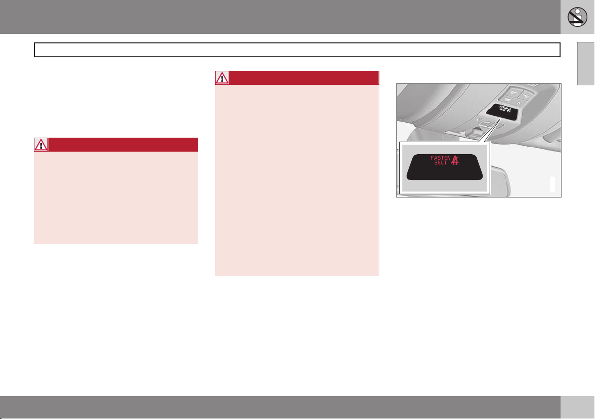
Seat belt reminder
G017726
Seat belt reminder light in ceiling console
The seat belt reminder consists of an audible
signal, an indicator light near the rearview
mirror and a symbol in the instrument panel
that alert all occupants of the vehicle to fasten their seat belts. The audible signal and
indicator light will be on for several seconds
from the time the ignition is switched on,
regardless of whether or not the seat belts
are fastened.
If the front seat belts are unbuckled while the
vehicle is in motion, the audible signal and
warning light will be active for a several seconds.
Page 22
01 Safety
Seat belts
01
20
Rear seats
The seat belt reminder in the rear seat has
two additional functions:
•
It provides information about which seat
belts are fastened in the rear seat. A message will appear in the information display
when a belt is being used. This message
will disappear after several seconds or
can be erased by pressing the OK button
on the left steering wheel lever.
•
It also provides a reminder if one of the
occupants of the rear seat has unbuckled
his/her seat belt while the vehicle is in
motion. A visual and audible signal will be
given. These signals will stop when the
seat belt has been re-buckled or can be
stopped by pressing the OK button.
•
The message
Unbelted in rear seat will
appear in the information display if one of
the rear doors has been opened.
The message in the information display can
always be accessed, even if it has been
erased, by pressing the OK button to display
stored messages.
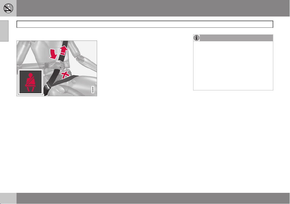
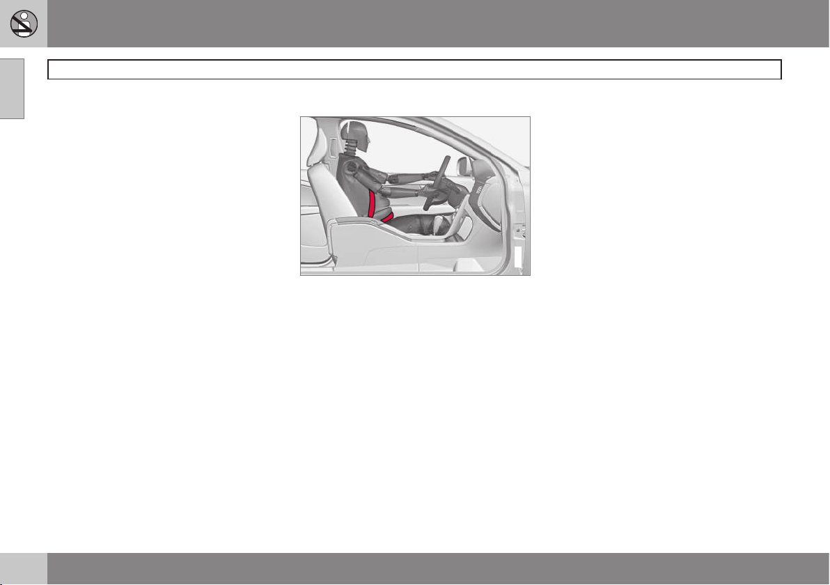
Seat belt use during pregnancy
G020998
The seat belt should always be worn during
pregnancy. But it is crucial that it be worn in
the correct way. The diagonal section should
wrap over the shoulder then be routed
between the breasts and to the side of the
belly. The lap section should lay flat over the
thighs and as low as possible under the belly.
It must never be allowed to ride upward.
Remove all slack from the belt and ensure
that it fits close to the body without any
twists.
As a pregnancy progresses, pregnant drivers
should adjust their seats and steering wheel
such that they can easily maintain control of
the vehicle as they drive (which means they
must be able to easily operate the foot pedals
and steering wheel). Within this context, they
should strive to position the seat with as large
a distance as possible between their belly
and the steering wheel.
Child seats
Please refer to page 40 for information on
securing child seats with the seat belts.
Page 23
01 Safety
Supplemental Restraint System (SRS)
01
* Option/accessory, for more information, see Introduction.
21
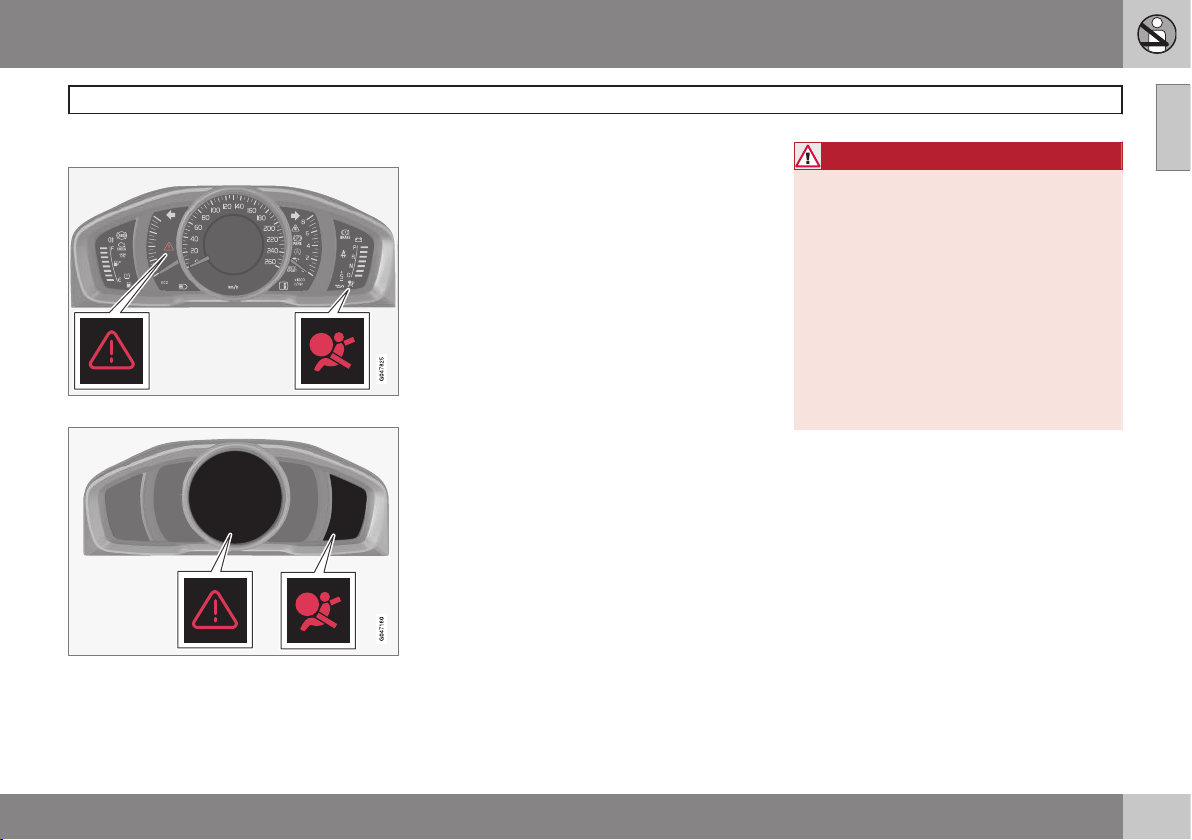
General information
Models with an analog instrument panel
Models with an digital instrument panel*
As an enhancement to the three-point seat
belts, your Volvo is equipped with a Supplemental Restraint System (SRS). Volvo's SRS
consists of seat belt pretensioners, front airbags, side impact airbags, a front passenger
occupant weight sensor, and inflatable curtains. All of these systems are monitored by
the SRS control module. An SRS warning
light in the instrument panel (see the illustration) illuminates when the ignition is in modes
I or II, and will normally go out after approximately 6 seconds if no faults are detected in
the system.
Where applicable, a text message will also be
displayed when the SRS warning light illuminates. If this warning symbol is not functioning properly, the general warning symbol illuminates and a text message will be displayed.
See also page 79 for more information
about indicator and warning lights.
WARNING
•
If the SRS warning light stays on after
the engine has started or if it illuminates while you are driving, have the
vehicle inspected by a trained and
qualified Volvo service technician as
soon as possible.
•
Never try to repair any component or
part of the SRS yourself. Any interference in the system could cause malfunction and serious injury. All work on
these systems should be performed by
a trained and qualified Volvo service
technician.
Page 24
01 Safety
Supplemental Restraint System (SRS)
01
22
WARNING
If your vehicle has become flood-damaged
in any way (e.g., soaked carpeting/standing water on the floor of the vehicle), do
not attempt to start the vehicle or insert
the remote key into the ignition slot before
disconnecting the battery (see below). This
may cause airbag deployment which could
result in serious injury. Have the vehicle
towed to a trained and qualified Volvo
service technician for repairs.
Before attempting to tow the vehicle:
1. Switch off the ignition for at least
10 minutes and disconnect the battery.
2. Follow the instructions for manually
overriding the shiftlock system on
page 128.
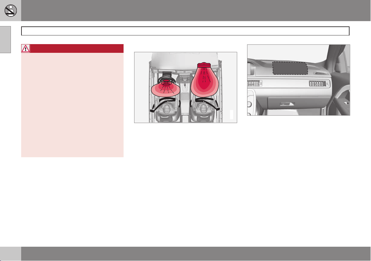
Front airbags
G018665
The front airbag system
The front airbags supplement the three-point
seat belts. For these airbags to provide the
protection intended, seat belts must be worn
at all times.
The front airbag system includes gas generators surrounded by the airbags, and deceleration sensors that activate the gas generators,
causing the airbags to be inflated with nitrogen gas.
Location of the passenger's side front airbag
As the movement of the seats' occupants
compresses the airbags, some of the gas is
expelled at a controlled rate to provide better
cushioning. Both seat belt pretensioners also
deploy, minimizing seat belt slack. The entire
process, including inflation and deflation of
the airbags, takes approximately one fifth of a
second.
The location of the front airbags is indicated
by SRS AIRBAG embossed on the steering
wheel pad and above the glove compartment,
and by decals on both sun visors and on the
front and far right side of the dash.
The driver's side front airbag is folded and
located in the steering wheel hub.
Page 25
01 Safety
Supplemental Restraint System (SRS)
01
23
The passenger's side front airbag is folded
behind a panel located above the glove compartment.
WARNING
•
The airbags in the vehicle are designed
to be a SUPPLEMENT to–not a
replacement for–the three-point seat
belts. For maximum protection, wear
seat belts at all times. Be aware that
no system can prevent all possible
injuries that may occur in an accident.
•
Never drive with your hands on the
steering wheel pad/airbag housing.
•
The front airbags are designed to help
prevent serious injury. Deployment
occurs very quickly and with considerable force. During normal deployment
and depending on variables such as
seating position, one may experience
abrasions, bruises, swellings, or other
injuries as a result from deployment of
one or both of the airbags.
•
When installing any accessory equipment, make sure that the front airbag
system is not damaged. Any interference in the system could cause malfunction.
Front airbag deployment
•
The front airbags are designed to deploy
during certain frontal or front-angular collisions, impacts, or decelerations,
depending on the crash severity, angle,
speed and object impacted. The airbags
may also deploy in certain non-frontal
collisions where rapid deceleration
occurs.
•
The SRS sensors, which trigger the front
airbags, are designed to react to both the
impact of the collision and the inertial
forces generated by it, and to determine if
the intensity of the collision is sufficient
for the seat belt pretensioners and/or airbags to be deployed.
However, not all frontal collisions activate the
front airbags.
•
If the collision involves a nonrigid object
(e.g., a snow drift or bush), or a rigid,
fixed object at a low speed, the front airbags will not necessarily deploy.
•
Front airbags do not normally deploy in a
side impact collision, in a collision from
the rear or in a rollover situation.
•
The amount of damage to the bodywork
does not reliably indicate if the airbags
should have deployed or not.
WARNING
•
Do not use child safety seats or child
booster cushions/backrests in the
front passenger's seat. We also recommend that occupants under 4 feet
7 inches (140 cm) in height who have
outgrown these devices sit in the rear
seat with the seat belt fastened1.
•
Never drive with the airbags deployed.
The fact that they hang out can impair
the steering of your vehicle. Other
safety systems can also be damaged.
•
The smoke and dust formed when the
airbags are deployed can cause skin
and eye irritation in the event of prolonged exposure.
Should you have questions about any component in the SRS system, please contact a
trained and qualified Volvo service technician
or Volvo customer support:
In the USA
Volvo Cars of North America, LLC
Customer Care Center
1 Volvo Drive
P.O. Box 914
1
See also the Occupant Weight Sensor information on page 26.
Page 26
01 Safety
Supplemental Restraint System (SRS)
01
24
Rockleigh, New Jersey 07647
1-800-458-1552
www.volvocars.com/us
In Canada
Volvo Cars of Canada Corp.
National Customer Service
9130 Leslie Street, Suite 101
Richmond Hill, Ontario L4B 0B9
1-800-663-8255
www.volvocars.com/ca
NOTE
•
Deployment of front airbags occurs
only one time during an accident. In a
collision where deployment occurs,
the airbags and seat belt pretensioners
activate. Some noise occurs and a
small amount of powder is released.
The release of the powder may appear
as smoke-like matter. This is a normal
characteristic and does not indicate
fire.
•
Volvo's front airbags use special sensors that are integrated with the front
seat buckles. The point at which the
airbag deploys is determined by
whether or not the seat belt is being
used, as well as the severity of the collision.
•
Collisions can occur where only one of
the airbags deploys. If the impact is
less severe, but severe enough to
present a clear injury risk, the airbags
are triggered at partial capacity. If the
impact is more severe, the airbags are
triggered at full capacity.
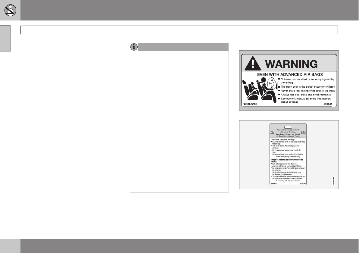
Airbag decals
G008335
Airbag decal on the outside of both sun visors
Passenger's side airbag decal
Page 27
01 Safety
Supplemental Restraint System (SRS)
01
25
WARNING
•
Children must never be allowed in the
front passenger's seat.
•
Occupants in the front passenger's
seat must never sit on the edge of the
seat, sit leaning toward the instrument
panel or otherwise sit out of position.
•
The occupant's back must be as
upright as comfort allows and be
against the seat back with the seat
belt properly fastened.
•
Feet must be on the floor, e.g., not on
the dash, seat or out of the window.
WARNING
•
No objects or accessory equipment,
e.g. dashboard covers, may be placed
on, attached to, or installed near the
air bag hatch (the area above the glove
compartment) or the area affected by
airbag deployment (see the illustration
on page 22).
•
There should be no loose articles,
such as coffee cups on the floor, seat,
or dashboard area.
•
Never try to open the airbag cover on
the steering wheel or the passenger's
side dashboard. This should only be
done by a trained and qualified Volvo
service technician.
•
Failure to follow these instructions can
result in injury to the vehicle occupants.
Page 28
01 Safety
Occupant Weight Sensor
01
26
General information
2
2
G017724
Occupant Weight Sensor (OWS) indicator light
Disabling the passenger's side front
airbag
Volvo recommends that ALL occupants
(adults and children) shorter than 4 feet
7 inches (140 cm) be seated in the back seat
of any vehicle with a front passenger side airbag, and be properly restrained for their size
and weight. For child safety recommendations,see page 38.
The Occupant Weight Sensor (OWS) is
designed to meet the regulatory requirements
of Federal Motor Vehicle Safety Standard
(FMVSS) 208 and is designed to disable (will
not inflate) the passenger's side front airbag
under certain conditions.
The OWS works with sensors that are part of
the front passenger's seat and seat belt. The
sensors are designed to detect the presence
of a properly seated occupant and determine
if the passenger's side front airbag should be
enabled (may inflate) or disabled (will not
inflate).
The OWS will disable (will not inflate) the passenger's side front airbag when:
•
the front passenger's seat is unoccupied,
or has small/medium objects in the front
seat,
•
the system determines that an infant is
present in a rear-facing infant seat that is
installed according to the manufacturer's
instructions,
•
the system determines that a small child
is present in a forward-facing child
restraint that is installed according to the
manufacturer's instructions,
•
the system determines that a small child
is present in a booster seat,
•
a front passenger takes his/her weight off
of the seat for a period of time,
•
a child or a small person occupies the
front passenger's seat.
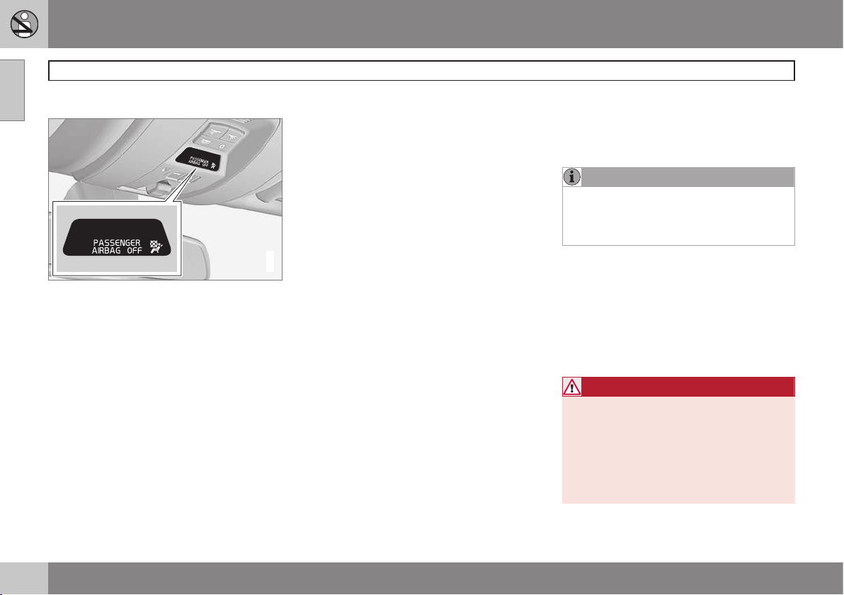
The OWS uses a PASSENGER AIRBAG OFF
indicator lamp which will illuminate and stay
on to remind you that the passenger's side
front airbag is disabled. The PASSENGER
AIRBAG OFF indicator lamp is located in the
overhead console, near the base of the rearview mirror.
NOTE
When the ignition is switched on, the OWS
indicator light will go on for up to 10 seconds while the system performs a selfdiagnostic test.
However, if a fault is detected in the system:
•
The OWS indicator light will stay on
•
The SRS warning light (see page 21) will
come on and stay on
•
The message
Pass. Airbag OFF Service
urgent will be displayed in the informa-
tion display.
WARNING
If a fault in the system is detected and
indicated as described, be aware that the
passenger's side front airbag will not
deploy in the event of a collision. In this
case, the SRS system and Occupant
Weight Sensor should be inspected by a
trained and qualified Volvo service technician as soon as possible.
Page 29
01 Safety
Occupant Weight Sensor
01
27
WARNING
•
Never try to open, remove, or repair
any components in the OWS system.
This could result in system malfunction. Maintenance or repairs should
only be carried out by an a trained and
qualified Volvo service technician.
•
The front passenger's seat should not
be modified in any way. This could
reduce pressure on the seat cushion,
which might interfere with the OWS
system's function.
Passenger's seat
occupancy status
OWS
indicator
light status
Passenger's side
front airbag status
Seat unoccupied
OWS indicator light
lights up.
Passenger's
side front airbag disabled
Seat occupied by low
weight
occupant/
object
A
OWS indicator light
lights up
Passenger's
side front airbag disabled
Seat occupied by
heavy occupant/object
OWS indicator light
is not lit
Passenger's
side front airbag enabled
A
Volvo recommends that children always be properly
restrained in appropriate child restraints in the rear seats.
Do not assume that the passenger's side front airbag is
disabled unless the PASSENGER AIRBAG OFF indicator
lamp is lit. Make sure the child restraint is properly installed. If there is any doubt as to the status of the passenger's side front airbag, move the child restraint to the rear
seat.
The OWS is designed to enable (may inflate)
the passenger's side front airbag in the event
of a collision anytime the system senses that
a person of adult size is sitting properly in the
front passenger's seat. The PASSENGER
AIRBAG OFF indicator lamp will be off and
remain off.
If a person of adult size is sitting in the front
passenger's seat, but the PASSENGER AIRBAG OFF indicator lamp is on, it is possible
that the person isn't sitting properly in the
seat. If this happens:
•
Turn the vehicle off and ask the person to
place the seatback in an upright position.
•
Have the person sit upright in the seat,
centered on the seat cushion, with the
person's legs comfortably extended.
•
Restart the vehicle and have the person
remain in this position for about two
minutes. This will allow the system to
detect that person and enable the passenger's frontal airbag.
•
If the PASSENGER AIRBAG OFF indicator lamp remains on even after this, the
person should be advised to ride in the
rear seat.
This condition reflects limitations of the OWS
classification capability. It does not indicate
OWS malfunction.
Modifications
If you are considering modifying your vehicle
in any way to accommodate a disability, for
example by altering or adapting the driver's
Page 30
01 Safety
Occupant Weight Sensor
01
28
or front passenger's seat(s) and/or airbag
systems, please contact Volvo at:
In the USA
Volvo Cars of North America, LLC
Customer Care Center
1 Volvo Drive
P.O. Box 914
Rockleigh, New Jersey 07647
1-800-458-1552
In Canada
Volvo Cars of Canada Corp.
National Customer Service
9130 Leslie Street, Suite 101
Richmond Hill, Ontario L4B 0B9
1-800-663-8255
WARNING
•
No objects that add to the total weight
on the seat should be placed on the
front passenger's seat. If a child is
seated in the front passenger's seat
with any additional weight, this extra
weight could cause the OWS system
to enable the airbag, which might
cause it to deploy in the event of a collision, thereby injuring the child.
•
The seat belt should never be wrapped
around an object on the front passenger's seat. This could interfere with
the OWS system's function.
•
The front passenger's seat belt should
never be used in a way that exerts
more pressure on the passenger than
normal. This could increase the pressure exerted on the weight sensor by a
child, and could result in the airbag
being enabled, which might cause it to
deploy in the event of a collision,
thereby injuring the child.
WARNING
•
Keep the following points in mind with
respect to the OWS system. Failure to
follow these instructions could
adversely affect the system's function
and result in serious injury to the occupant of the front passenger's seat:
•
The full weight of the front seat passenger should always be on the seat
cushion. The passenger should never
lift him/herself off the seat cushion
using the armrest in the door or the
center console, by pressing the feet on
the floor, by sitting on the edge of the
seat cushion, or by pressing against
the backrest in a way that reduces
pressure on the seat cushion. This
could cause OWS to disable the front,
passenger's side airbag.
Page 31

01 Safety
Occupant Weight Sensor
01
29
WARNING
•
Do not place any type of object on the
front passenger's seat in such a way
that jamming, pressing, or squeezing
occurs between the object and the
front seat, other than as a direct result
of the correct use of the Automatic
Locking Retractor/Emergency Locking
Retractor (ALR/ELR) seat belt (see
page 38).
•
No objects should be placed under the
front passenger's seat. This could
interfere with the OWS system's function.
Page 32

01 Safety
Side impact protection (SIPS) airbags
01
30
General information
G032949
Location of the side impact (SIPS) airbags (front
seats only)
As an enhancement to the structural side
impact protection built into your vehicle, it is
also equipped with Side Impact Protection
System (SIPS) airbags.
The SIPS airbag system is designed to help
increase occupant protection in the event of
certain side impact collisions. The SIPS airbags are designed to deploy only during certain side-impact collisions, depending on the
crash severity, angle, speed and point of
impact.
G024377
Driver's side SIPS airbag
G024378
Passenger's side SIPS airbag
NOTE
SIPS airbag deployment (one airbag)
occurs only on the side of the vehicle
affected by the impact. The airbags are not
designed to deploy in all side impact situations.
Components in the SIPS airbag system
This SIPS airbag system consists of a gas
generator, the side airbag modules built into
the outboard sides of both front seat backrests, and electronic sensors/wiring.
Page 33

01 Safety
Side impact protection (SIPS) airbags
01
31
WARNING
•
The SIPS airbag system is a supplement to the structural Side Impact
Protection System and the three-point
seat belt system. It is not designed to
deploy during collisions from the front
or rear of the vehicle or in rollover situations.
•
The use of seat covers on the front
seats may impede SIPS airbag deployment.
•
No objects, accessory equipment or
stickers may be placed on, attached to
or installed near the SIPS airbag system or in the area affected by SIPS airbag deployment.
•
Never try to open or repair any components of the SIPS airbag system. This
should be done only by a trained and
qualified Volvo service technician.
•
In order for the SIPS airbag to provide
its best protection, both front seat
occupants should sit in an upright
position with the seat belt properly fastened.
•
Failure to follow these instructions can
result in injury to the occupants of the
vehicle in the event of an accident.
Page 34

01 Safety
Inflatable Curtain (IC)
01
32
General information
This system consists of inflatable curtains
located along the sides of the roof liners,
stretching from the center of both front side
windows to the rear edge of the rear side
door windows. It is designed to help protect
the heads of the occupants of the front seats
and the occupant of the outboard rear seating positions in certain side impact collisions.
In certain side impacts, both the Inflatable
Curtain (IC) and the Side Impact Airbag System (SIPS airbag) will deploy. The IC and the
SIPS airbag deploy simultaneously.
NOTE
If the inflatable curtain deploys, it remains
inflated for approximately 3 seconds.
WARNING
•
The IC system is a supplement to the
Side Impact Protection System. It is
not designed to deploy during collisions from the rear of the vehicle or in
rollover situations.
•
Never try to open or repair any components of the IC system. This should be
done only by a trained and qualified
Volvo service technician.
•
Never hang heavy items from the ceiling handles. This could impede
deployment of the Inflatable Curtain.
•
The cargo area and rear seat should
not be loaded to a level higher than
2 in. (5 cm) below the upper edge of
the rear side windows. Objects placed
higher than this level could impede the
function of the Inflatable Curtain.
WARNING
In order for the IC to provide its best protection, both front seat occupants and
both outboard rear seat occupants should
sit in an upright position with the seat belt
properly fastened; adults using the seat
belt and children using the proper child
restraint system. Only adults should sit in
the front seats. Children must never be
allowed in the front passenger seat, see
page 38 for guidelines. Failure to follow
these instructions can result in injury to the
vehicle occupants in an accident.
Page 35

01 Safety
Whiplash Protection System – WHIPS
01
33
General information
Whiplash Protection System (WHIPS) –
front seats only
The WHIPS system consists of specially
designed hinges and brackets on the front
seat backrests designed to help absorb some
of the energy generated in a collision from the
rear (when the vehicle is rear-ended).
In the event of a collision of this type, the
hinges and brackets of the front seat backrests are designed to change position slightly
to allow the backrest/head restraint to help
support the occupant's head before moving
slightly rearward. This movement helps
absorb some of the forces that could result in
whiplash.
WARNING
•
The WHIPS system is designed to
supplement the other safety systems
in your vehicle. For this system to
function properly, the three-point seat
belt must be worn. Please be aware
that no system can prevent all possible
injuries that may occur in an accident.
•
The WHIPS system is designed to
function in certain collisions from the
rear, depending on the crash severity,
angle and speed.
WARNING
•
Occupants in the front seats must
never sit out of position. The occupant's back must be as upright as
comfort allows and be against the seat
back with the seat belt properly fastened.
•
If your vehicle has been involved in a
rear-end collision, the front seat backrests must be inspected by a trained
and qualified Volvo service technician,
even if the seats appear to be undamaged. Certain components in the
WHIPS system may need to be
replaced.
•
Do not attempt to service any component in the WHIPS system yourself.
Page 36

01 Safety
Whiplash Protection System – WHIPS
01
34
WARNING
•
Boxes, suitcases, etc. wedged behind
the front seats could impede the function of the WHIPS system.
•
If the rear seat backrests are folded
down, cargo must be secured to prevent it from sliding forward against the
front seat backrests in the event of a
collision from the rear. This could
interfere with the action of the WHIPS
system.
WARNING
Any contact between the front seat backrests and the folded rear seat or a rearfacing child seat could impede the function
of the WHIPS system. If the rear seat is
folded down, the occupied front seats
must be adjusted forward so that they do
not touch the folded rear seat.
Page 37

01 Safety
Crash mode
01
* Option/accessory, for more information, see Introduction.
35
Warning symbol: analog instrument panel
Warning symbol: digital instrument panel*
Driving after a collision
If the vehicle has been involved in a collision,
the text
Safety mode See manual may
appear in the information display. This indi-
cates that the vehicle's functionality has been
reduced.
NOTE
This text can only be shown if the display
is undamaged and the vehicle's electrical
system is intact.
Safety mode is a feature that is triggered if
one or more of the safety systems (e.g. front
or side airbags, an inflatable curtain, or one or
more of the seat belt pretensioners) has
deployed. The collision may have damaged
an important function in the vehicle, such as
the fuel lines, sensors for one of the safety
systems, the brake system, etc.
WARNING
•
Never attempt to repair the vehicle
yourself or to reset the electrical system after the vehicle has displayed
Safety mode See manual. This could
result in injury or improper system
function.
•
Restoring the vehicle to normal operating status should only be done by a
trained and qualified Volvo service
technician.
•
After
Safety mode See manual has
been displayed, if you detect the odor
of fuel vapor, or see any signs of fuel
leakage, do not attempt to start the
vehicle. Leave the vehicle immediately.
Attempting to start the vehicle
If damage to the vehicle is minor and there is
no fuel leakage, you may attempt to start the
vehicle. To do so:
1. Remove the remote key from the ignition
slot and open the driver's door. If a message is displayed that the ignition is on,
press the start button.
2. Close the driver's door and reinsert the
remote key in the ignition slot.
3. Try to start the vehicle.
Page 38

01 Safety
Crash mode
01
36
If the message Safety mode See manual is
still displayed, the vehicle should not be
driven and must be towed. Concealed faults
may make the vehicle difficult to control.
Moving the vehicle
If the message Normal mode is displayed
when Safety mode See manual is no longer
displayed, the vehicle may be moved carefully from its present position, if for example,
it is blocking traffic. It should, however, not
be moved farther than is absolutely necessary.
WARNING
Even if the vehicle appears to be drivable
after Safety mode has been set, it should
not be driven or towed (pulled by another
vehicle). There may be concealed damage
that could make it difficult or impossible to
control. The vehicle should be transported
on a flatbed tow truck to a trained and
qualified Volvo service technician for
inspection/repairs.
Page 39

01 Safety
Child safety
01
}}
37
Children should be seated safely
Volvo recommends the proper use of restraint
systems for all occupants including children.
Remember that, regardless of age and size, a
child should always be properly restrained in
a vehicle.
Your vehicle is also equipped with ISOFIX/
LATCH attachments, which make it more
convenient to install child seats.
Some restraint systems for children are
designed to be secured in the vehicle by lap
belts or the lap portion of a lap-shoulder belt.
Such child restraint systems can help protect
children in vehicles in the event of an accident only if they are used properly. However,
children could be endangered in a crash if the
child restraints are not properly secured in the
vehicle. Failure to follow the installation
instructions for your child restraint can result
in your child striking the vehicle's interior in a
sudden stop.
Holding a child in your arms is NOT a suitable
substitute for a child restraint system. In an
accident, a child held in a person's arms can
be crushed between the vehicle's interior and
an unrestrained person. The child could also
be injured by striking the interior, or by being
ejected from the vehicle during a sudden
maneuver or impact. The same can also happen if the infant or child rides unrestrained on
the seat. Other occupants should also be
properly restrained to help reduce the chance
of injuring or increasing the injury of a child.
All states and provinces have legislation governing how and where children should be carried in a vehicle. Find out the regulations
existing in your state or province. Recent
accident statistics have shown that children
are safer in rear seating positions than front
seating positions when properly restrained. A
child restraint system can help protect a child
in a vehicle. Here's what to look for when
selecting a child restraint system:
It should have a label certifying that it meets
applicable Federal Motor Vehicle Safety
Standards (FMVSS 213) – or in Canada,
CMVSS 213.
Make sure the child restraint system is
approved for the child's height, weight and
development – the label required by the
standard or regulation, or instructions for
infant restraints, typically provide this information.
In using any child restraint system, we urge
you to carefully look over the instructions that
are provided with the restraint. Be sure you
understand them and can use the device
properly and safely in this vehicle. A misused
child restraint system can result in increased
injuries for both the infant or child and other
occupants in the vehicle.
When a child has outgrown the child safety
seat, you should use the rear seat with the
standard seat belt fastened. The best way to
help protect the child here is to place the
child on a cushion so that the seat belt is
properly located on the hips (see the illustration on page 46). Legislation in your state or
province may mandate the use of a child seat
or cushion in combination with the seat belt,
depending on the child's age and/or size.
Please check local regulations.
A specially designed and tested booster
cushion and backrest can be obtained from
your Volvo retailer.
USA: for children weighing 33 – 80 lbs. (15 –
36 kg) and 38 – 54 inches (97 – 137 cm) in
height
Canada: for children weighing 40 – 80 lbs.
(18 – 36 kg) and 40 – 54 inches (102 –
137 cm) in height
Page 40

01 Safety
Child safety
01
38
WARNING
•
Do not use child safety seats or child
booster cushions/backrests in the
front passenger's seat. We also recommend that children under 4 feet
7 inches (140 cm) in height who have
outgrown these devices sit in the rear
seat with the seat belt fastened.
•
On hot days, the temperature in the
vehicle interior can rise very quickly.
Exposure to these high temperatures
for even a short period of time can
cause heat-related injury or death.
Small children are particularly at risk.
Child seat should always be registered. See
page 39 for more information.
Automatic Locking Retractor/ Emergency Locking Retractor (ALR/ ELR)
To make child seat installation easier, each
seat belt (except for the driver's belt) is equipped with a locking mechanism to help keep
the seat belt taut.
When attaching the seat belt to a child seat:
1. Attach the seat belt to the child seat
according to the child seat manufacturer's instructions.
2. Pull the seat belt out as far as possible.
3. Insert the seat belt latch plate into the
buckle (lock) in the usual way.
4. Release the seat belt and pull it taut
around the child seat.
A sound from the seat belt retractor will be
audible at this time and is normal. The belt
will now be locked in place. This function is
automatically disabled when the seat belt is
unlocked and the belt is fully retracted.
WARNING
Do not use child safety seats or child
booster cushions/backrests in the front
passenger's seat. We also recommend
that children who have outgrown these
devices sit in the rear seat with the seat
belt properly fastened.
Volvo's recommendations
Why does Volvo believe that no child should
sit in the front seat of a car? It's quite simple
really. A front airbag is a very powerful device
designed, by law, to help protect an adult.
Because of the size of the airbag and its
speed of inflation, a child should never be
placed in the front seat, even if he or she is
properly belted or strapped into a child safety
seat. Volvo has been an innovator in safety
for over seventy-five years, and we'll continue
to do our part. But we need your help. Please
remember to put your children in the back
seat, and buckle them up.
Volvo has some very specific recommendations:
•
Always wear your seat belt.
•
Airbags are a SUPPLEMENTAL safety
device which, when used with a threepoint seat belt can help reduce serious
injuries during certain types of accidents.
Volvo recommends that you do not disconnect the airbag system in your vehicle.
•
Volvo strongly recommends that everyone in the vehicle be properly restrained.
•
Volvo recommends that ALL occupants
(adults and children) shorter than 4 feet
7 inches (140 cm) be seated in the back
Page 41

01 Safety
Child safety
01
39
seat of any vehicle with a front passenger
side airbag.
•
Drive safely!
Child restraint registration and recalls
Registering a child restraint
Child restraints could be recalled for safety
reasons. You must register your child
restraint to be reached in a recall. To stay
informed about child safety seat recalls, be
sure to fill out and return the registration card
that comes with new child restraints.
Child restraint recall information is readily
available in both the U.S. and Canada. For
recall information in the U.S., call the U.S.
Government's Auto Safety Hotline at
1-800-424-9393 or go to http://wwwodi.nhtsa.dot.gov/cars/problems/recalls/
register/childseat/index.cfm. In Canada, visit
Transport Canada's Child Safety website at
http://www.tc.gc.ca/roadsafety/childsafety/
menu.htm.
Page 42

01 Safety
Child restraint systems
01
40
Child restraints
G022840
Infant seat
There are three main types of child restraint
systems: infant seats, convertible seats, and
booster cushions. They are classified according to the child's age and size.
The following section provides general infor-
mation on securing a child restraint using a
three-point seat belt. Refer to page 47–49
for information on securing a child restraint
using ISOFIX/LATCH lower anchors and/or
top tether anchorages.
G022847
Convertible seat
WARNING
A child seat should never be used in the
front passenger seat of any vehicle with a
front passenger airbag – not even if the
"Passenger airbag off" symbol near the
rear-view mirror is illuminated (on vehicles
equipped with Occupant Weight Sensor). If
the severity of an accident were to cause
the airbag to inflate, this could lead to serious injury or death to a child seated in this
position.
G023269
Booster cushion
WARNING
Always refer to the child restraint manufacturer's instructions for detailed information
on securing the restraint.
Page 43

01 Safety
Child restraint systems
01
41
WARNING
•
When not in use, keep the child
restraint system secured or remove it
from the passenger compartment to
help prevent it from injuring passengers in the event of a sudden stop or
collision.
•
A small child's head represents a considerable part of its total weight and its
neck is still very weak. Volvo recommends that children up to age 4 travel,
properly restrained, facing rearward. In
addition, Volvo recommends that children should ride rearward facing,
properly restrained, as long as possible.
Page 44

01 Safety
Infant seats
01
42
Securing an infant seat with a seat belt
G022844
Do not place the infant seat in the front passenger's seat
NOTE
Refer to page 47–49 for information on
securing a child restraint using ISOFIX/
LATCH lower anchors and/or top tether
anchorages.
1. Place the infant seat in the rear seat of
the vehicle.
2. Attach the seat belt to the infant seat
according to the manufacturer's instructions.
G023270
Positioning the seat belt through the infant seat
WARNING
•
An infant seat must be in the rear-facing
position only.
•
The infant seat should not be positioned
behind the driver's seat unless there is
adequate space for safe installation.
WARNING
A child seat should never be used in the
front passenger seat of any vehicle with a
front passenger airbag – not even if the
"Passenger airbag off" symbol near the
rear-view mirror is illuminated (on vehicles
equipped with Occupant Weight Sensor). If
the severity of an accident were to cause
the airbag to inflate, this could lead to serious injury or death to a child seated in this
position.
3. Fasten the seat belt by inserting the latch
plate into the buckle (lock) until a distinct
click is audible.
G023271
Fasten the seat belt
Page 45

01 Safety
Infant seats
01
43
G022846
Pull out the shoulder section of the seat belt
4. Pull the shoulder section of the seat belt
out as far as possible to activate the
belt's automatic locking function.
NOTE
The locking retractor will automatically
release when the seat belt is unbuckled
and allowed to retract fully.
5. Press the infant seat firmly in place, let
the seat belt retract and pull it taut. A
sound from the seat belt retractor's automatic locking function will be audible at
this time and is normal. The seat belt
should now be locked in place.
G022850
Ensure that the seat is securely in place
6. Push and pull the infant seat along the
seat belt path to ensure that it is held
securely in place by the seat belt.
WARNING
It should not be possible to move the child
restraint (child seat) more than 1 in.
(2.5 cm) in any direction along the seat belt
path.
The infant seat can be removed by unbuckling the seat belt and letting it retract completely.
Page 46

01 Safety
Convertible seats
01
44
Securing a convertible seat with a seat belt
G018630
Do not place the convertible seat in the front
passenger's seat
NOTE
Refer to pages 47 and 49 for information on securing a child restraint using
ISOFIX/LATCH lower anchors and/or top
tether anchorages.
Convertible seats can be used in either a forward or rearward-facing position, depending
on the age and size of the child.
G022847
Route the seat belt through the convertible seat
WARNING
Always use a convertible seat that is suitable for the child's age and size. See the
convertible seat manufacturer's recommendations.
1. Place the convertible seat in the rear seat
of the vehicle.
WARNING
•
A small child's head represents a considerable part of its total weight and its
neck is still very weak. Volvo recommends that children up to age 4 travel,
properly restrained, facing rearward. In
addition, Volvo recommends that children should ride rearward facing, properly restrained, as long as possible.
•
Convertible child seats should be installed in the rear seat only.
•
A rear-facing convertible seat should
not be positioned behind the driver's
seat unless there is adequate space for
safe installation.
2. Attach the seat belt to the convertible
seat according to the manufacturer's
instructions.
Page 47

01 Safety
Convertible seats
01
45
G022848
Fasten the seat belt
3. Fasten the seat belt by inserting the latch
plate into the buckle (lock) until a distinct
click is audible.
4. Pull the shoulder section of the seat belt
out as far as possible to activate the
belt's automatic locking function.
NOTE
The locking retractor will automatically
release when the seat belt is unbuckled
and allowed to retract fully.
5. Press the convertible seat firmly in place,
let the seat belt retract and pull it taut. A
sound from the seat belt retractor's automatic locking function will be audible at
this time and is normal. The seat belt
should now be locked in place.
G022849
Pull out the shoulder section of the seat belt
6. Push and pull the convertible seat along
the seat belt path to ensure that it is held
securely in place by the seat belt.
WARNING
It should not be possible to move the child
restraint (child seat) more than 1 in.
(2.5 cm) in any direction along the seat belt
path.
The convertible seat can be removed by
unbuckling the seat belt and letting it retract
completely.
G022850
Ensure that the seat is securely in place
WARNING
A child seat should never be used in the
front passenger seat of any vehicle with a
front passenger airbag – not even if the
"Passenger airbag off" symbol near the
rear-view mirror is illuminated. If the
severity of an accident were to cause the
airbag to inflate, this could lead to serious
injury or death to a child seated in this
position.
Page 48

01 Safety
Booster cushions
01
46
Securing a booster cushion
G022851
Position the child correctly on the booster cushion
Booster cushions are recommended for children who have outgrown convertible seats.
1. Place the booster cushion in the rear seat
of the vehicle.
2. With the child properly seated on the
booster cushion, attach the seat belt to or
around the cushion according to the
manufacturer's instructions.
3. Fasten the seat belt by inserting the latch
plate into the buckle (lock) until a distinct
click is audible.
G022852
Positioning the seat belt
4. Ensure that the seat belt is pulled taut
and fits snugly around the child.
WARNING
•
The hip section of the three-point seat
belt must fit snugly across the child's
hips, not across the stomach.
•
The shoulder section of the three-point
seat belt should be positioned across
the chest and shoulder.
•
The shoulder belt must never be
placed behind the child's back or
under the arm.
Page 49

01 Safety
ISOFIX/LATCH lower anchors
01
47
Using the ISOFIX/LATCH lower child seat anchors
Lower anchors for ISOFIX/LATCH-equipped
child seats are located in the rear, outboard
seats, hidden below the backrest cushions.
Symbols on the seat back upholstery mark
the anchor positions as shown. To access the
anchors, kneel on the seat cushion and locate
the anchors by feel. Always follow your child
seat manufacturer's installation instructions,
and use both ISOFIX/LATCH lower anchors
and top tethers whenever possible.
To access the anchors
1. Put the child restraint in position.
2. Kneel on the child restraint to press down
the seat cushion and locate the anchors
by feel.
3. Fasten the attachment on the child
restraint's lower straps to the ISOFIX/
LATCH/LATCH lower anchors.
4. Firmly tension the lower child seat straps
according to the manufacturer's instructions.
WARNING
Volvo's ISOFIX/LATCH anchors conform to
FMVSS/CMVSS standards. Always refer to
the child restraint system's manual for
weight and size ratings.
NOTE
•
The rear seat's center position is not
equipped with ISOFIX/LATCH lower
anchors. When installing a child
restraint in this position, attach the
restraint's top tether strap (if it is so
equipped) to the top tether anchorage
point and secure the restraint with the
vehicle's center seat belt.
•
Always follow your child seat manufacturer's installation instructions, and
use both ISOFIX/LATCH lower anchors
and top tethers whenever possible.
G018631
Fasten the attachment correctly to the ISOFIX/
LATCH lower anchors
Page 50

01 Safety
ISOFIX/LATCH lower anchors
01
48
WARNING
•
Be sure to fasten the attachment correctly to the anchor (see the illustration). If the attachment is not correctly
fastened, the child restraint may not
be properly secured in the event of a
collision.
•
The ISOFIX/LATCH lower child
restraint anchors are only intended for
use with child seats positioned in the
outboard seating positions. These
anchors are not certified for use with
any child restraint that is positioned in
the center seating position. When
securing a child restraint in the center
seating position, use only the vehicle's
center seat belt.
Page 51

01 Safety
Top tether anchors
01
49
Child restraint anchorages
Your Volvo is equipped with child restraint
top tether anchorages in the rear seat. They
are located on the rear side of the backrests.
Securing a child seat
1. Place the child restraint on the rear seat.
2. Route the top tether strap under the head
restraint and attach it to the anchor.
3. Attach lower tether straps to the lower
ISOFIX/LATCH anchors. If the child
restraint is not equipped with lower tether
straps, or the restraint is used in the center seating position, follow instructions for
securing a child restraint using the Automatic Locking Retractor seat belt (see
page 38).
4. Firmly tension all straps.
Refer also to the child seat manufacturer's
instructions for information on securing the
child seat.
NOTE
On models equipped with the optional
cargo area cover, this cover should be
removed before a child seat is attached to
the child restraint anchors.
WARNING
•
Always refer to the recommendations
made by the child restraint manufacturer.
•
Volvo recommends that the top tether
anchors be used when installing a forward-facing child restraint.
•
Never route a top tether strap over the
top of the head restraint. The strap
should be routed beneath the head
restraint.
•
Child restraint anchorages are
designed to withstand only those
loads imposed by correctly fitted child
restraints. Under no circumstances are
they to be used for adult seat belts or
harnesses. The anchorages are not
able to withstand excessive forces on
them in the event of collision if full harness seat belts or adult seat belts are
installed to them. An adult who uses a
belt anchored in a child restraint
anchorage runs a great risk of suffering severe injuries should a collision
occur.
•
Do not install rear speakers that
require the removal of the top tether
anchors or interfere with the proper
use of the top tether strap.
Page 52

01 Safety
Integrated booster cushion*
01
50
* Option/accessory, for more information, see Introduction.
Integrated two-stage booster
cushion
1
Volvo's optional integrated booster cushions
are located in the outboard seating positions.
These booster cushions have been specially
designed to help safeguard children in the
rear seat. They should be stowed (folded
down into the seat cushion) when not in use.
When using an integrated booster cushion,
the child must be secured with the vehicle's
three-point seat belt.
Use these booster cushions only
with children whose weight is
between:
•
Stage 1: 48 – 80 lbs (22 – 36 kg)
•
Stage 2: 33 – 55 lbs (15 – 25 kg)
and whose height is between:
•
Stage 1: 45 – 55 in. (115 –
140 cm)
•
Stage 2: 37 – 47 in. (95 – 120 cm)
In Canada, Transport Canada's
weight recommendation is 40 –
80 lbs (18 – 36 kg).
The booster cushions are designed to raise
the child higher, so that the shoulder strap
crosses over the child's collarbone, not over
the child's neck. If using a booster cushion
does not result in proper positioning of the
shoulder strap, then the child should be
placed in a properly secured child restraint
(see page 40). The shoulder belt must never
be placed behind the child's back or under
the arm.
G017875
Correct seating position: child's head is below
the head restraint and the shoulder belt is across
the collarbone
G017719
Incorrect seating position: the child's head is
above the head restraint and the shoulder belt is
not across the collarbone
Before driving, check that:
•
The integrated two-stage booster cushion
is set in the correct position according to
the child's height and weight (see the
table below) and is locked in position.
Stage 1 Stage 2
Weight 48 – 80 lbs
22 – 36 kg
33 – 55 lbs
15 – 25 kg
Height 45 – 55 in.
115 – 140 cm
37 – 47 in.
95 – 120 cm
1
Canada only: This cushion may be referred to as a built-in booster cushion.
Page 53

01 Safety
Integrated booster cushion*
01
}}
* Option/accessory, for more information, see Introduction.
51
•
That the seat belt is properly positioned
and is taut.
•
The shoulder section of the seat belt is
across the child's collarbone, not over the
neck.
•
The lap section of the seat belt is across
the child's hips and not the abdomen.
Using an integrated booster cushion
Stage 1
G017697
Pull the handle (1) forward and upward (2)
to release the booster cushion.
Press the booster cushion rearward to
lock it in position.
Stage 2
G017784
With the booster cushion in the stage 1
position, press the button (see the arrow
in illustration 1).
Lift the front edge of the booster cushion
and press it rearward toward the backrest
to lock it in position.
Page 54

01 Safety
Integrated booster cushion*
01
52
* Option/accessory, for more information, see Introduction.
Stowing the two-stage integrated
booster cushion
The booster cushion can be folded down
completely (stowed) from either the stage 1 or
stage 2 positions.
NOTE
The booster cushion cannot be moved
from the stage 2 (upper) position to the
stage 1 (lower) position. It must first be
folded down completely to the stowed
position, and then adjusted to stage 1.
Pull the handle forward to release the
booster cushion.
Press down on the center of the booster
cushion to return it to the stowed position.
NOTE
The booster cushion must be in the
stowed position before the rear seat backrests are folded down.
CAUTION
Be sure there are no loose objects under
the booster cushion before it is stowed.
WARNING
DEATH or SERIOUS INJURY can
occur
Follow all instructions on the
booster cushion and in the vehicle's owner's manual.
MAKE SURE THE BOOSTER
CUSHION IS SECURELY
LOCKED BEFORE THE CHILD IS
SEATED.
•
Use this booster cushion only with
children whose height and weight are
within the permitted limits shown in
the table (see page 50).
•
In the event of a collision while the
integrated booster cushion was occupied, the entire booster cushion and
seat belt must be replaced. The
booster cushion should also be
replaced if it is badly worn or damaged
in any way. This work should be performed by a trained and qualified
Volvo service technician only.
Page 55

01 Safety
Child safety locks
01
* Option/accessory, for more information, see Introduction.
53
Child safety locks
G021077
Child safety locks – rear doors
The controls are located on the rear door
jambs. Use the remote control's key blade or
a screwdriver to adjust these controls.
The rear doors can only be opened from
the outside when the slot is in the horizontal position.
The rear doors can be opened from the
inside when the slot is in the vertical position.
Power child safety locks and
disengaging rear door windows*
Driver's door control panel
The power child safety locks can be activated/deactivated when the remote key is in
mode I (see page 87) or higher. Activation/
deactivation can be done up to 2 minutes
after the engine has been switched off (if no
door has been opened).
To activate the child safety locks:
1. Put the ignition in mode I or higher or
start the engine.
2. Press the button on the driver's door control panel (see the illustration).
>
Rear child locks Activated will be
displayed in the instrument panel and
the indicator light in the button will illuminate when the function is activated.
When the child safety locks are activated:
•
The rear door windows can only be
opened from the driver's door control
panel
•
The rear doors cannot be opened from
the inside
The child safety locks' current setting is
stored when the engine is switched off. If
these locks were activated when the engine
was switched off, they will also be active
when the engine is restarted.
Page 56

54
Remote key and key blade..................................................................... 56
Private locking ........................................................................................ 65
Keyless drive........................................................................................... 66
Locks....................................................................................................... 69
Alarm....................................................................................................... 72
Page 57

LOCKS AND ALARM
Page 58

02 Locks and alarm
Remote key and key blade
02
56
Introduction
Two remote keys or optional Personal Car
Communicators (PCC) are provided with your
vehicle. They enable you to unlock the doors
and tailgate, and also function as ignition
keys to start the vehicle or operate electrical
components. The remote keys contain
detachable metal key blades for manually
locking or unlocking the driver's door and the
glove compartment. The visible ends of these
key blades are unique to make it easier to
identify "your" remote key. Up to six remotes
can be programmed for use on the same
vehicle.
The PCCs have enhanced functionality compared with the standard remote key.
NOTE
In the remainder of this chapter, all references to the remote key also pertain to the
PCC unless otherwise stated.
WARNING
Never leave the remote key in the ignition
slot if children are to remain in the vehicle.
See page 86 for more information on the
various ignition modes.
Detachable key blade
Each remote key or PCC contains a detachable metal key blade for mechanically locking
or unlocking the driver's door and the glove
compartment, and to enable the private locking function. See page 62 for more information on the key blade and page 65 for information on the private locking function. The
key blades have a unique code, which is used
if new ones need to be produced. This code
is available at an authorized Volvo retailer.
The visible ends of these key blades are
unique to make it easier to identify "your"
remote key.
Loss of a remote key
If either of the remote keys is lost, the other
should be taken with the car to a Volvo
retailer. As an anti-theft measure, the code of
the lost remote key must be erased from the
system.
NOTE
Additional or duplicate remote control keys
can be obtained from any Authorized
Volvo Retailer.
You can also obtain additional or duplicate
remote control keys from certain independent repair facilities and locksmiths
that are qualified to make remote control
keys. Each key must be programmed to
work with your vehicle.
California Only:
A list of independent repair facilities and/or
locksmiths known to Volvo that can cut
and code replacement keys can be found:
•
on the Volvo website at
http://www.volvocars.com/us/keys
•
by calling Volvo Customer Care at
1-800-458-1552
The number of registered keys for the vehicle
can be found by pressing MY CAR and going
into
Settings Information Number of
keys
. See page 199 for a description of the
menu system.
USA-5WK49264
FCC ID:KR55WK49264 + Siemens VDO
5WK49236
FCC ID:KR55WK49236, 5WK49266
Page 59

02 Locks and alarm
Remote key and key blade
02
* Option/accessory, for more information, see Introduction.
57
FCC ID:KR55WK49266 + Siemens VDO
5WK49233
FCC ID:KR55WK49233
This device complies with part 15 of the FCC
rules and RSS-210. Operation is subject to
the following conditions: (1) This device may
not cause harmful interference, and (2) this
device must accept any interference
received, including interference that may
cause undesired operation.
Canada-5WK49264
IC:267T-5WK49264 + Siemens VDO
5WK49236
IC:267T-5WK49236, 5WK49266
IC:267T-5WK49266 + Siemens VDO
5WK49233
IC:267T-5WK49233
Operation is subject to the following condi-
tions: (1) this device may not cause interference, and (2) this device must accept any
interference, including interference that may
cause undesired operation of the device.
Key memory: door mirrors and driver's
seat
The position of the side door mirrors, power
driver's seat* and the selected instrument
panel theme1 are stored in the remote keys
when the vehicle is locked. The next time the
driver's door is unlocked with the same
remote key and the door is opened within
2 minutes, the power driver's seat and side
door mirrors will automatically move to the
position that they were in when the doors
were most recently locked with the same
remote key. If the seat/mirrors have not been
readjusted since the vehicle was locked, they
will already be in the position stored in that
particular remote key and will not move. See
page 89 for more information. See also
page 90 for more information on this feature.
This feature can be activated or deactivated
in the vehicle's menu by pressing MY CAR
and going into
Settings Car settings
Car key memory. See page 199 for a
description of the menu system.
See also page 66 for information regarding
vehicles with the optional keyless drive.
Confirmation when locking/unlocking
the vehicle
Settings can be made in the menu system for
audible and visual confirmation when the
vehicle has been locked or unlocked. With
these functions activated, the following will
occur when the vehicle is locked/unlocked:
Locking confirmation
•
The turn signals flash once, an audible
signal sounds and the door mirrors will
fold* in.
Confirmation will only be given when all doors
and the tailgate are properly closed and
locked.
NOTE
If you do not receive confirmation when
locking the vehicle, check whether a door
or the tailgate is ajar, or if this feature has
been turned off in the menu.
Unlocking confirmation
•
The turn signals will flash twice and the
door mirrors will fold* out.
Making a setting
Different alternatives for locking/unlocking
confirmation can be selected in the menus by
1
Optional digital instrument panel only
Page 60

02 Locks and alarm
Remote key and key blade
02
58
pressing MY CAR on the center console control panel.
•
To activate visual confirmation: go to
Settings Car settings Light
settings
and select Door lock
confirmation light and/or Unlock
confirmation light by pressing OK/
MENU.
•
To activate audible confirmation: go to
Settings Car settings Lock
settings
and select Audible
confirmation by pressing OK/MENU.
See page 199 for a description of the menu
system.
Immobilizer (start inhibitor)
Each of the keys supplied with your vehicle
contains a coded transponder. The code in
the key is transmitted to an antenna in the
ignition slot where it is compared to the code
stored in the start inhibitor module. The vehicle will start only with a properly coded key. If
you misplace a key, take the other keys to a
trained and qualified Volvo service technician
for reprogramming as an anti-theft measure.
The following messages (which may appear
in the instrument panel display) are related to
the immobilizer:
Message Meaning
Insert car
key
Remote key not recognized
during start. Try to start the
vehicle again.
Car key
not found
PCC with keyless drive only.
Remote key not recognized
during start. Try to start the
vehicle again.
If the problem continues,
insert the remote key into
the ignition slot and try to
start the vehicle again.
Immobilizer Try
start
again
Remote key fault during
start. Contact an authorized
Volvo workshop.
CAUTION
Never use force when inserting the remote
key in the ignition slot. The vehicle cannot
be started if the transponder is damaged.
USA–FCC ID: LTQWFS 125VO
This device complies with part 15 of the FCC
rules. Operation is subject to the following
condition: (1) This device may not cause
harmful interference, and (2) this device must
accept any interference received, including
interference that may cause undesired operation.
Canada–IC: 3659A-WFS125VO
Operation is subject to the following condi-
tions: (1) this device may not cause interference, and (2) this device must accept any
interference, including interference that may
cause undesired operation of the device.
See page 120 for information on starting the
vehicle.
Replacing the battery in the remote key
The batteries should be replaced if:
•
The information symbol illuminates and
Low battery in remote control. Please
change batteries. is shown in the dis-
play and/or
•
if the locks do not react after several
attempts to unlock or lock the vehicle.
NOTE
The remote key's range is normally
approximately 60 ft (20 m) from the vehicle.
See page 62 for information about replacing
the battery.
Page 61

02 Locks and alarm
Remote key and key blade
02
}}
* Option/accessory, for more information, see Introduction.
59
Remote key/Personal Car
Communicator (PCC)* - common
functions
Standard remote key
Lock
Unlock
Approach lighting
Tailgate unlock
Panic alarm
Personal Car Communicator (PCC)*
Lock
Unlock
Approach lighting
Tailgate unlock
Panic alarm
Information button (see page 60)
Buttons on the remote
Lock – Press the Lock button on the
remote once to lock all doors and the tailgate.
The turn signals will flash once to confirm
locking.
Unlock – Press the Unlock button on the
remote once to unlock the driver's door.
After a short pause, press the Unlock button
a second time within 10 seconds to unlock
the other doors and the tailgate.
This function can be changed so that all
doors unlock at the same time by pressing
My Car and going to
Settings Car
settings
Lock settings Change doors
unlock setting
. See page 199 for a descrip-
tion of the menu system.
Approach lighting – As you approach
the vehicle, press the button on the remote
key to light the interior lighting, parking lights,
license plate lighting and the lights in the door
mirrors*.
These lights will switch off automatically after
30, 60 or 90 seconds. See page 199 for a
description of the menu system.
Unlock tailgate – Press the button twice
within several seconds to disarm the alarm
system (the alarm indicator light on the dashboard will go out), and unlock only the tailgate. Pressing this button for several seconds
also opens the tailgate on models equipped
with the optional power tailgate.
Page 62

02 Locks and alarm
Remote key and key blade
02
60
* Option/accessory, for more information, see Introduction.
NOTE
As an added safety precaution, the parking
lights will come on automatically for a
short period when the tailgate has been
opened.
After closing, the tailgate will not automatically relock. Press Lock to relock it and rearm
the alarm.
See also the section "Unlocking the tailgate
from the passenger compartment."
Panic alarm – This button can be used
to attract attention during emergency situations.
To activate the panic alarm, press and hold
this button for at least 3 seconds or press it
twice within 3 seconds. The turn signals and
horn will be activated. The panic alarm will
stop automatically after 2 minutes and
45 seconds.
To deactivate, wait approximately 5 seconds
and press the button again.
The Panic alarm button will not unlock the
vehicle.
Range
The remote key has a range of approximately
60 ft. (20 m) from the vehicle.
NOTE
Buildings or other obstacles may interfere
with the function of the remote key. The
vehicle can also be locked or unlocked
with the key blade, see page 62.
If the remote key is removed from the vehicle
while the engine is running or if the ignition is
in mode I or II and all of the doors are closed,
a message will appear in the instrument panel
display and there will be an audible signal.
When the remote key is returned to the vehicle, the message will be erased and the audible signal will stop after one of the following
has been done:
•
The remote key is inserted in the ignition
slot
•
The vehicle's speed exceeds 20 mph
(30 km/h)
•
The OK button on the left steering wheel
lever is pressed
Unique functions—PCC*
Information button
Indicator lights
Pressing the information button provides certain information about the vehicle with the
help of the indicator lights.
Using the information button
1.
Press the information button
.
2. All of the indicator lights will flash
sequentially for approximately 7 seconds
to indicate that the PCC is receiving information from the vehicle. If any of the buttons are pressed during this 7-second
period, transmission of information to the
PCC will be interrupted.
Page 63

02 Locks and alarm
Remote key and key blade
02
61
NOTE
If none of the indicator lights flash when
the information button has been pressed
several times from different places in relation to the vehicle, contact an authorized
Volvo service technician.
The indicator lights provide information
according to the illustration:
Steady green light: the vehicle is correctly
locked.
Steady yellow light: the vehicle is not
locked.
Steady red light: the alarm has been triggered since the vehicle was most recently
locked.
Both red lights flash alternatively: the
alarm was triggered less than 5 minutes
ago.
Range
The PCC's lock and unlock functions have a
range of approximately 60 ft. (20 m) from the
vehicle.
NOTE
•
The approach lighting, panic alarm,
and the functions controlled by the
information button have a range of
approximately 300 ft (100 m) from the
vehicle.
•
Radio waves, buildings or other obstacles may interfere with the function of
the PCC.
If the vehicle does not provide confirmation
when a button has been pressed, try moving
closer and pressing the button again.
Outside of the PCC´s range
If the PCC is more than approximately 300 ft
(100 m) from the vehicle when the information
button is pressed, no new information will be
received. The PCC most recently used to lock
or unlock the vehicle will show the vehicle's
most recently received status. The indicator
lights will not flash when the information button is pressed while the PCC is out of range.
If more than one PCC is used to lock/unlock
the vehicle, only the one used most recently
will show the correct locking status.
NOTE
If none of the indicator lights illuminate
when the information button is pressed,
this may be because the most recent
transmission between the vehicle and the
PCC was interrupted or impeded by buildings or other objects.
Keyless drive
Vehicles equipped with the optional Personal
Car Communicator have the keyless drive
function, see page 66 for detailed information.
Page 64

02 Locks and alarm
Remote key and key blade
02
62
* Option/accessory, for more information, see Introduction.
Detachable key blade
The key blade can be removed from the
remote key. When removed, the key blade
can be used to:
•
Lock/unlock the driver's door if the
remote key is not functioning properly
•
Lock/unlock the glove compartment (see
page 70)
•
Override the transmission's shiftlock system (see page 128)
•
Enable/disable the private locking function (see page 65)
Removing the key blade
Slide the spring loaded catch to the side.
Pull the key blade straight out of the
remote key.
Reinserting the key blade in the remote key
1. Hold the remote key with the slot for the
key blade up.
2. Carefully slide the key blade into its
groove.
3. Gently press the key blade in the groove
until it clicks into place.
Unlocking the driver's door with the detached key blade
Driver's door keyhole cover
If the remote key/PCC* does not function normally (weak battery, etc.), the vehicle can be
unlocked with the detachable key blade.
1. Remove the key blade from the remote
key/PCC (see the previous section,
"Removing the key blade" on page 62 for
instructions).
2. Press the key blade approx. 0.5 in. (1 cm)
straight up in the hole on the underside of
the keyhole cover.
> The cover will come off due to the
pressure exerted when the key blade is
pushed upward.
3. Insert the key blade as far as possible in
the driver's door lock. Turn the key blade
to unlock the driver's door. This will trig-
ger the alarm.
4. To turn off the alarm, insert the remote
key in the ignition slot. This also applies
to vehicles equipped with the optional
keyless drive.
5. Press the cover back into place after the
door has been unlocked.
Replacing batteries in the remote key/PCC
The battery/batteries in the remote key/PCC
should be replaced if:
•
The information symbol lights up and a
text appears in the information display.
and/or
•
the vehicle's locks repeatedly do not
react when a button on the remote
Page 65

02 Locks and alarm
Remote key and key blade
02
63
key/PCC is pressed within approximately
60 ft (20 m) from the vehicle.
Battery type CR 2430, 3 V (one battery in the
remote key, two batteries in the PCC)
Opening the remote key/PCC
Slide the spring loaded catch to the
side.
Pull the key blade straight out of the
remote key.
Insert a small screwdriver in the hole
behind the spring loaded catch and carefully pry up the cover.
NOTE
Turn the remote key with the buttons
upward so that the batteries do not fall out
when the cover is removed.
Replacing the batteries
CAUTION
When handling batteries, avoid touching
their contact surfaces as this could result
in poor battery function in the remote key.
Note the position of the battery's (+) or (–)
sides.
Remote key (one battery)
1. Use a screwdriver to pry out the old battery.
2. Insert a new one with the (+) side downward.
PCC (two batteries)
1. Use a screwdriver to pry out the old batteries.
2. Insert the first new battery with the (+)
side upward.
3. Insert the plastic spacer over the battery.
Insert the second new battery on top of
the plastic spacer, with the + side downward.
Re-assembling the remote key
1. Press the remote key's cover into place.
2. Hold the remote key with the slot for the
key blade up.
Page 66

02 Locks and alarm
Remote key and key blade
02
64
3. Carefully slide the key blade into its
groove.
4. Gently press the key blade in the groove
until it clicks into place.
Old batteries should be properly recycled.
Page 67

02 Locks and alarm
Private locking
02
65
Tailgate compartment
G017869
Normal locking/unlocking points
G017870
Locking/unlocking points with private locking
activated.
By utilizing the remote key with the key blade
removed, the private locking feature enables
you to block access to the glove compartment and disconnect the tailgate from the
central locking system for e.g., valet parking
or when the vehicle is brought to the retailer
for service.
With the private locking function activated:
•
The vehicle's doors can be locked or
unlocked with the remote
•
The engine can be started
•
The glove compartment cannot be
unlocked
•
The tailgate cannot be unlocked or
opened with the remote
•
The rear floor hatch cannot be opened
NOTE
The floor hatch must be closed completely
before the tailgate can be closed.
Activating the private locking function
Insert the key blade in the glove compartment lock.
Turn the key blade180 degrees clockwise.
Remove the key blade from the lock. A
message will appear in the instrument
panel display.
Deactivating the private locking
function
Turn the key blade 180 degrees counterclockwise in the glove compartment lock to
deactivate private locking.
See page 70 for information on locking the
glove compartment normally, without activating the private locking function.
Page 68

02 Locks and alarm
Keyless drive
02
66
* Option/accessory, for more information, see Introduction.
Keyless drive* (models with Personal
Car Communicator only)
Keyless locking and unlocking
Range of the keyless drive remote key–5 ft
(1.5 meters)
This system makes it possible to unlock and
lock the vehicle without having to press any
buttons on the Personal Car Communicators
(PCC). It is only necessary to have a keyless
drive remote key in your possession to operate the central locking system.
NOTE
•
The gear selector must in the P position before the vehicle can be locked
and the alarm can be armed.
•
The buttons on the keyless drive
remote key can also be used to lock
and unlock the vehicle, see page 59
for more information.
Both of the PCCs provided with the vehicle
have the keyless function, and additional
ones can be ordered. The system can
accommodate up to six PCCs.
The red rings in the illustration indicate the
area around the vehicle that is within range of
the keyless drive antennas.
Unlocking the vehicle
•
A keyless drive remote key must be on
the same side of the vehicle as the door
to be opened, and be within 5 feet
(1.5 meters) of the door's lock or the tailgate (see the shaded areas in the illustration).
•
Pull a door handle to unlock and open the
door or pull the tailgate opening control.
The number of doors that are unlocked at the
same time can be set in the vehicle's menu
system. Press MY CAR and go to
Car
settings Lock settings Keyless entry.
See page 199 for a description of the menu
system.
Unlocking the vehicle with the key
blade
Keyless drive keyhole cover
If the PCC does not function normally (weak
battery, etc.), the vehicle can be unlocked
with the detachable key blade. See page 62
for instructions.
Page 69

02 Locks and alarm
Keyless drive
02
67
Locking the vehicle
Models with keyless drive have a button on the
outside door handles
The doors and the tailgate can be locked by
pressing the lock button in any of the outside
door handles.
NOTE
On keyless drive vehicles, the gear selector must be in the Park (P) position, all
doors and the tailgate must be closed and
the ignition must be switched off before
the vehicle can be locked.
Keyless drive remote key and driver's
seat/door mirror memory
•
When you leave the vehicle with a PCC in
your possession and lock any door, the
position of the driver's seat and door mirrors will be stored in the seat's memory.
•
The next time a door is opened by a person with the same PCC in his/her possession, the driver's seat and door mirrors will automatically move to the position that they were in when the door was
most recently locked.
NOTE
If several people carrying PCCs approach
the vehicle at the same time, the driver's
seat and door mirrors will assume the
positions they were in for the person who
opens the driver's door.
See also page 89 for information on adjusting and storing the seat's position in the seat
memory.
Keyless drive information messages
If all of the PCCs are removed from the vehicle while the engine is running or if the ignition is in mode II (see page 86) and all of
the doors are closed, a message will appear
in the instrument panel display and an audible
signal will sound.
When at least one PCC has been returned to
the car, the message will be erased in the display and the audible signal will stop when:
•
A door has been opened and closed
•
The PCC has been inserted in the ignition
slot
•
The OK button (see page 197 for the
location of this button) has been pressed.
CAUTION
•
Keyless drive remote keys should
never be left in the vehicle. In the event
of a break-in, a remote found in the
vehicle could make it possible to start
the engine.
•
Electromagnetic fields or metal
obstructions can interfere with the
keyless drive system. The remote key
should never be placed closer than
approximately 4-6 in. (10-15 cm) to
cell phones, metallic objects or e.g.,
stored in a metal briefcase.
USA – FCC ID:KR55WK48952,
KR55WK48964
NOTE
This device complies with part 15 of the FCC
Rules. Operation is subject to the following
two conditions: (1) This device may not cause
harmful interference, and (2) this device must
accept interference received, including interference that may cause undesired operation.
Page 70

02 Locks and alarm
Keyless drive
02
68
CAUTION
Changes or modifications not expressly
approved by the manufacturer could void the
user's authority to operate the equipment.
Siemens VDO
5WK48891
Tested To Comply With FCC Standards
For Automobile Use
Canada – IC:267T-5WK48952,
267T-5WK48964, 267T-5WK48891
NOTE
This device complies with RSS -210 of Indus-
try Canada. Operation is subject to the following two conditions: (1) This device may
not cause harmful interference, and (2) this
device must accept interference received,
including interference that may cause undesired operation.
CAUTION
Changes or modifications not expressly
approved by the manufacturer could void the
user's authority to operate the equipment.
Location of the keyless drive antennas
The keyless drive system has a number of
antennas located at various points in the
vehicle.
On the tailgate, near the wiper motor
Left rear door handle
Under the floor of the cargo area, near
the rear seat
Right rear door handle
Under the rear section of the center console
Under the front section of the center console
WARNING
People with implanted pacemakers should
not allow the pacemaker to come closer
than 9 inches (22 cm) to any of the keyless
drive system's antennas. This is to help
prevent interference between the pacemaker and the keyless drive system.
Page 71

02 Locks and alarm
Locks
02
69
Locking and unlocking the vehicle
From outside the vehicle
The remote key locks and unlocks all of the
doors and the tailgate.
Before the vehicle can be locked from the
outside with the remote key, the driver's door
must be closed. Any other door/tailgate that
is open will be locked and the alarm will be
armed.
NOTE
Be sure the remote key is outside of the
vehicle before the other doors/tailgate are
closed to help avoid locking the remote
inside the vehicle.
If the vehicle is equipped with the optional
keyless drive system, all doors/tailgate must
be closed before the vehicle can be locked.
The first press on the unlock button unlocks
the driver's door and a second press unlocks
the other doors and the tailgate (see also
page 59). This setting can be changed in the
menu system. See page 199 for a description.
If the locks repeatedly do not react when the
unlock button is pressed, it may be necessary
to replace the batteries in the remote, see
page 58. In this case the vehicle can be
unlocked with the detachable key blade. See
page 62.
From inside the vehicle (central locking
button)
Central locking button
The lock buttons on the door panel can be
used to lock or unlock all doors and the tail-
gate at the same time. Press
to lock and
to unlock.
Unlocking
The vehicle can be unlocked from inside the
vehicle in two ways:
•
By pressing the unlock button
.
•
The door can be unlocked by pulling the
door handle once and opened by pulling
the handle again.
Locking
•
Press the lock button
after the front
doors have been closed.
•
Each door can be locked individually with
the lock button on the respective doors.
The door must be closed first.
Alternative locking when parking
The central locking button on the driver's
door can also be used to lock the vehicle
when you leave it. To do so:
1. Open the door.
2. Press the lock section of the button.
3. Close the door. This will lock the vehicle
completely and arm the alarm.
NOTE
Please be aware that locking the vehicle in
this way makes it possible to lock the
remote key in the passenger compartment.
To help avoid this, lock the vehicle from
the outside by pressing the lock button on
the remote key.
If the vehicle is locked using the central
locking button, be sure that the remote key
is in your possession before closing the
door.
Page 72

02 Locks and alarm
Locks
02
70
Automatic relocking
If the doors are unlocked, the locks will automatically reengage (re-lock) and the alarm will
rearm after 2 minutes unless a door or the
tailgate has been opened.
Automatic locking
When the vehicle starts to move, the doors
and tailgate can be locked automatically. This
feature can be turned on or off by pressing
MY CAR and going to
Car settings Lock
settings
Automatic door locking. See
page 199 for a description of the menu system.
Glove compartment
The glove compartment can only be locked
and unlocked using the detachable key blade
in the remote key. See page 62 for information on removing the key blade from the
remote key.
Insert the key blade in the glove compartment lock.
Turn the key blade 90 degrees clockwise.
Remove the key blade from the lock.
Locking/unlocking the tailgate
Tailgate unlock button on the remote key
Unlocking the tailgate with the remote
key
– Press the tailgate unlock button on the
remote key to unlock (but not open1) the
tailgate. See also page 59.
> The alarm indicator light on the dash-
board will go out to indicate that the
alarm is not monitoring the entire vehicle.
NOTE
•
If the doors are locked while the tailgate is open, the tailgate will remain
unlocked until the vehicle is relocked
by pressing the Lock button on the
remote key.
•
On keyless drive vehicles, the gear
selector must be in the Park (P) position, all doors and the tailgate must be
closed and the ignition must be
switched off before the vehicle can be
locked.
1
This button also opens, but does not close, the tailgate on models equipped with the optional power tailgate (see page 283).
Page 73

02 Locks and alarm
Locks
02
71
Unlocking the tailgate from the driver's
seat
– Press the button on the lighting panel (1)
to unlock (but not open1) the tailgate.
NOTE
The taillights will illuminate automatically
for a short period when the tailgate has
been opened.
Locking the tailgate with the remote
key
Press the lock button ( ) on the remote.
See also page 59
The alarm indicator on the dashboard will
begin flashing to show that the vehicle is
locked and that the alarm has been armed.
1
This button also opens, but does not close, the tailgate on models equipped with the optional power tailgate (see page 283).
Page 74

02 Locks and alarm
Alarm
02
72
The alarm system
The alarm is automatically armed whenever
the vehicle is locked with the remote key or
optional Personal Car Communicator.
When armed, the alarm continuously monitors a number of points on the vehicle. The
following conditions will trigger the alarm:
•
The hood is forced open.
•
The tailgate is forced open.
•
A door is forced open.
•
The ignition slot is tampered with.
•
An attempt is made to start the vehicle
with a non-approved key (a key not
coded to the car's ignition).
•
The battery is disconnected (while the
alarm is armed).
•
The siren is disconnected when the alarm
is disarmed.
A message will appear in the information display if a fault should occur in the alarm system. Contact a trained and qualified Volvo
service technician.
NOTE
Do not attempt to repair any of the components in the alarm system yourself. This
could affect the insurance policy on the
vehicle.
The alarm indicator light
The status of the alarm system is indicated by
the red indicator light on the dashboard (see
illustration):
•
Indicator light off: the alarm is not armed
•
The indicator light flashes at one-second
intervals: the alarm is armed
•
The indicator light flashes rapidly before
the remote key is inserted in the ignition
slot and the ignition is put in mode I: the
alarm has been triggered.
Arming the alarm
– Press the Lock button on the remote key.
One long flash of the turn signals will confirm that the alarm is armed.
Alarm confirmation settings can be changed
in MY CAR, under
Car settings Lock
settings
Keyless entry. See page 199 for
a description of the menu system.
USA FCC ID: MAYDA 5823(3)
This device complies with part 15 of the FCC
rules. Operation is subject to the following
conditions: (1) This device may not cause
harmful interference, and (2) this device must
accept any interference received, including
interference that may cause undesired operation.
Canada IC: 4405A-DA 5823(3)
This device is subject to the following conditions: (1) this device may not cause interference, and (2) this device must accept any
interference, including interference that may
cause undesired operation of the device.
Page 75

02 Locks and alarm
Alarm
02
73
Disarming the alarm
– Press the Unlock button on the remote
key.
> Two short flashes from the car's direc-
tion indicators confirm that the alarm
has been deactivated and that all
doors are unlocked.
Turning off (stopping) the alarm
If the alarm is sounding, it can be stopped by
pressing the Unlock button on the remote key
or by inserting the remote key in the ignition
slot. Two short flashes from the car's direction indicators confirm that the alarm has
been turned off.
Other alarm-related functions
Automatic re-arming
If the doors are unlocked, the locks will automatically re-engage (re-lock) and the alarm
will re-arm after 2 minutes unless a door or
the tailgate has been opened.
Audible/visual alarm signal
•
An audible alarm signal is given by a battery powered siren. The alarm cycle lasts
for 30 seconds.
•
The visual alarm signal is given by flashing all turn signals for approximately
5 minutes or until the alarm is turned off.
Remote key not functioning
If the remote key is not functioning properly,
the alarm can be turned off and the vehicle
can be started as follows:
1. Open the driver's door with the key blade
(see page 62 for information on detaching
the key blade).
> This will trigger the alarm.
2. Insert the remote key into the ignition slot
(also on vehicles with the optional keyless
drive). This will turn off the alarm.
3. Start the engine (see page 120 for
instructions).
Page 76

74
* Option/accessory, for more information, see Introduction.
Instruments and controls........................................................................ 76
Ignition modes........................................................................................ 86
Seats....................................................................................................... 88
Steering wheel........................................................................................ 95
Lighting................................................................................................... 97
Wipers and washers.............................................................................. 105
Windows............................................................................................... 108
Mirrors................................................................................................... 110
Digial compass*.................................................................................... 113
Power moonroof* ................................................................................. 115
HomeLink® Wireless Control System*.................................................. 117
Starting the engine................................................................................ 120
Transmission......................................................................................... 125
Eco Guide* and Power Meter*.............................................................. 129
Brakes................................................................................................... 131
Parking brake........................................................................................ 134
Hill Descent Control (HDC)*.................................................................. 137
Page 77

YOUR DRIVING ENVIRONMENT
Page 78

03 Your driving environment
Instruments and controls
03
76
Instrument overview
Page 79

03 Your driving environment
Instruments and controls
03
}}
* Option/accessory, for more information, see Introduction.
77
Function Page
Controls for menus and
messages, turn signals,
high/low beams, trip
computer
199,
102,
97, 215
Paddles for manually
shifting gears*
126
Cruise control 146
Horn, airbag 95, 22
Main instrument panel 77
Infotainment system/
Bluetooth hands-free
controls
230,
259
START/STOP ENGINE
button
86
Ignition slot 86
Display for infotainment
system functions and
menus
230,
197
Hazard warning flashers 102
Door handle –
Function Page
In-door control panels
(power windows, mirrors,
central locking button,
power child safety locks)
108,
110,
69,53
Controls for the infotainment system and menus
199,
230, 208
Climate system controls 208
Gear selector 125
Controls for active chassis (Four-C)*
222
Wipers and washers 105,
106
Steering wheel adjustment
95
Parking brake 134
Hood opening control 335
Power seat* adjustment
controls
88
Lighting panel, buttons
for opening fuel filler
door and unlocking the
tailgate
97,
280, 70
Instrument panel information displays
Information displays: analog instrument panel
Information displays: digital instrument panel*
These displays show information on some of
the vehicle's functions, such as cruise con-
Page 80

03 Your driving environment
Instruments and controls
03
78
* Option/accessory, for more information, see Introduction.
trol, the trip computer and messages. The
information is shown with text and symbols.
More detailed information can be found in the
descriptions of the functions that use the
information displays.
Gauges and indicators: analog instrument panel
Fuel gauge: When the indicator shows
one white marking1, a yellow indicator
light will illuminate to indicate a low fuel
level. See also 215 and 278 for additional information.
Eco meter: Indicates how economically
the vehicle is being driven. The higher the
needle moves on the scale, the more
economically the vehicle is being driven.
Speedometer
Tachometer: Shows engine speed in
thousands of revolutions per minute (rpm)
Gear indicator: Shows the currently
selected gear
Gauges and indicators: digital
instrument panel*
Different themes (display alternatives) can be
selected for the digital instrument panel:
•
Elegance
•
Eco
•
Performance
To change themes, press the OK button on
the left steering wheel lever and use the
thumb wheel to scroll to
Themes. Press OK
to confirm your choice.
Theme Elegance: gauges and indicators
Fuel gauge. When the indicator shows
one white marking, a yellow indicator light
will illuminate to indicate a low fuel level.
See also 215 and 278 for additional
information.
Coolant temperature gauge
Speedometer
Tachometer (engine speed in thousands
of revolutions per minute (rpm))
Gear indicator: Shows the currently
selected gear
1
When the message Distance to empty fuel tank: shows "
----", the marker turns red
Page 81

03 Your driving environment
Instruments and controls
03
}}
79
Theme Eco: gauges and indicators
Fuel gauge. When the indicator shows a
white marking, a yellow indicator light will
illuminate to indicate a low fuel level. See
also 215 and 278 for additional information.
Eco Guide (see page 129)
Speedometer
Tachometer (engine speed in thousands
of revolutions per minute (rpm))
Gear indicator: Shows the currently
selected gear
Theme Performance: gauges and indicators
Fuel gauge. When the indicator shows a
white marking, a yellow indicator light will
illuminate to indicate a low fuel level. See
also 215 and 278 for additional information.
Coolant temperature gauge
Speedometer
Tachometer (shows engine speed in
thousands of revolutions per minute
(rpm))
Power Meter (see page 129).
Gear indicator: Shows the currently
selected gear
Indicator and warning symbols
Indicator and warning symbols: analog instrument panel
Indicator symbols
Indicator and warning symbols
Warning symbols
Page 82

03 Your driving environment
Instruments and controls
03
80
* Option/accessory, for more information, see Introduction.
Indicator and warning symbols: digital instrument
panel
Indicator symbols
Indicator and warning symbols
Warning symbols
Function check
All indicator and warning symbols light up in
ignition mode II or when the engine is started.
When the engine has started, all the symbols
should go out except the parking brake symbol, which only goes out when the brake is
disengaged.
If the engine does not start or if the function
check is carried out in ignition mode II, all
symbols go out after 5 seconds except the
malfunction indicator light, which may indi-
cate a fault in the vehicle's emissions system,
and the symbol for low oil pressure.
Some of the symbols shown may not be
available in all markets or models.
Indicator symbols
Symbol Description
Fault in the Active Bending
Light (ABL)*system
Malfunction indicator light
Anti-lock brake system (ABS)
Rear fog lights on
Stability system
The stability system's Sport
mode is activated
Low fuel level
Information symbol, read the
text displayed in the instrument
panel
High beam indicator
Symbol Description
Left turn signal indicator
Right turn signal indicator
Tire pressure monitoring sensor
(TPMS)
A
A
Option in Canada
Fault in the Active Bending Light
(ABL) system
This symbol will illuminate if there is a fault in
the ABL system. See page 100 for more
information about this system.
Malfunction Indicator Light
As you drive, a computer called On-Board
Diagnostics II (OBDII) monitors your vehicle's
engine, transmission, electrical and emission
systems.
The malfunction indicator light will illuminate if
the computer senses a condition that potentially may need correcting. When this happens, please have your vehicle checked by a
trained and qualified Volvo service technician
as soon as possible.
A malfunction indicator light may have many
causes. Sometimes, you may not notice a
Page 83

03 Your driving environment
Instruments and controls
03
* Option/accessory, for more information, see Introduction.
81
change in your car's behavior. Even so, an
uncorrected condition could hurt fuel economy, emission controls, and drivability.
Extended driving without correcting the cause
could even damage other components in
your vehicle.
This light may illuminate if the fuel filler cap is
not closed tightly or if the engine was running
while the vehicle was refueled.
Anti-lock Brake System (ABS)
If the warning light comes on, there may be a
malfunction in the ABS system (the standard
braking system will still function). Check the
system by:
1. Stopping in a safe place and switching off
the ignition.
2. Restart the engine.
3. If the warning light goes off, no further
action is required.
If the indicator light remains on, the vehicle
should be driven to a trained and qualified
Volvo service technician for inspection, see
page 131 for additional information.
Rear fog lights
This symbol indicates that the rear fog lights
are on.
Stability system
This indicator symbol flashes when the DSTC
(Dynamic Stability and Traction Control system) is actively working to stabilize the vehicle, see page 142 for more detailed information.
Sport mode
This symbol illuminates to indicate that the
stability system's Sport mode has been activated to help provide maximum tractive force,
for example when driving with snow chains,
or driving in deep snow or loose sand.
Low fuel level
When this light comes on, the vehicle should
be refueled as soon as possible. See page
278 for information about fuel and refueling.
Information symbol
The information symbol lights up and a text
message is displayed to provide the driver
with necessary information about one of the
vehicle's systems. The message can be
erased and the symbol can be turned off by
pressing the OK button (see page 197 for
information) or this will take place automatically after a short time (the length of time varies, depending on the function affected).
The information symbol may also illuminate
together with other symbols.
High beam indicator
This symbol illuminates when the high beam
headlights are on, or if the high beam flash
function is used.
Left turn signal indicator
Right turn signal indicator
NOTE
•
Both turn signal indicators will flash
when the hazard warning flashers are
used.
•
If either of these indicators flash faster
than normal, the direction indicators
are not functioning properly.
Tire pressure monitoring system
(TPMS)*
This symbol illuminates to indicate that tire
pressure in one or more tires is low, see
page 325 for detailed information.
Warning symbols
Symbol Description
Low oil pressure
Parking brake applied
Page 84

03 Your driving environment
Instruments and controls
03
82
Symbol Description
SRS airbags
Seat belt reminder
Generator not charging
Fault in the brake system
Warning symbol, read the text
displayed in the instrument
panel
Low oil pressure
If the light comes on while driving, stop the
vehicle, stop the engine immediately, and
check the engine oil level. Add oil if necessary. If the oil level is normal and the light
stays on after restart, have the vehicle towed
to the nearest trained and qualified Volvo
service technician.
Parking brake applied
This symbol flashes while the brake is being
applied and then glows steadily when the
parking brake has been set.
See page 134 for more information about
using the parking brake.
Airbags – SRS
If this light comes on while the vehicle is
being driven, or remains on for longer than
approximately 10 seconds after the vehicle
has been started, the SRS system's diagnostic functions have detected a fault in a seat
belt lock or pretensioner, a front airbag, side
impact airbag, and/or an inflatable curtain.
Have the system(s) inspected by a trained
and qualified Volvo service technician as
soon as possible.
See page 21 for more information about the
airbag system.
Seat belt reminder
This symbol comes on for approximately
6 seconds if the driver has not fastened his or
her seat belt.
Generator not charging
This symbol comes on during driving if a fault
has occurred in the electrical system. Contact
an authorized Volvo workshop.
Engine temperature
Engine overheating can result from low oil or
coolant levels, towing or hard driving at high
heat and altitude, or mechanical malfunction.
Engine overheating will be signaled with text
and a red warning triangle in the middle of the
instrument display. The exact text will depend
on the degree of overheating. It may range
from High engine temp Reduce speed to
High engine temp Stop engine. If appropri-
ate, other messages, such as Coolant level
low, Stop safely will also be displayed. If
your engine does overheat so that you must
stop the engine, always allow the engine to
cool before attempting to check oil and coolant levels.
See page 338 for more information.
Fault in brake system
If this symbol lights, the brake fluid level may
be too low. Stop the vehicle in a safe place
and check the level in the brake fluid reservoir, see page 338. If the level in the reservoir
is below MIN, the vehicle should be transported to an authorized Volvo workshop to have
the brake system checked.
If the
and symbols come on
at the same time, there may be a fault in the
brake force distribution system.
1. Stop the vehicle in a safe place and turn
off the engine.
2. Restart the engine.
•
If both symbols extinguish, continue driving.
•
If the symbols remain on, check the level
in the brake fluid reservoir, see page 338.
If the brake fluid level is normal but the
Page 85

03 Your driving environment
Instruments and controls
03
83
symbols are still lit, the vehicle can be
driven, with great care, to an authorized
Volvo workshop to have the brake system
checked.
•
If the level in the reservoir is below MIN,
the vehicle should be transported to an
authorized Volvo workshop to have the
brake system checked.
WARNING
•
If the fluid level is below the MIN mark
in the reservoir or if a warning message is displayed in the text window:
DO NOT DRIVE. Have the vehicle
towed to a trained and qualified Volvo
service technician and have the brake
system inspected.
•
If the
and symbols
are on at the same time, there is a risk
of reduced vehicle stability.
Warning symbol
The red warning symbol lights up to indicate
a problem related to safety and/or drivability.
A message will also appear in the instrument
panel. The symbol remains visible until the
fault has been rectified but the text message
can be cleared with the OK button, see
page 197. The warning symbol can also
come on in conjunction with other symbols.
Action:
1. Stop in a safe place. Do not drive the
vehicle further.
2. Read the information on the information
display. Implement the action in accordance with the message in the display.
Clear the message using OK.
Reminder – doors not closed
If one of the doors is not closed properly, the
information or warning symbol illuminates
(depending on the vehicle's speed), a graphic
will be displayed in instrument panel and an
explanatory text message2 will also be displayed in the instrument panel. Stop the vehicle in a safe place as soon as possible and
close the door.
If the vehicle is driven at a speed
lower than approximately 5 mph
(7 km/h), the information symbol illu-
minates.
If the vehicle is driven at a speed
higher than approximately 5 mph
(7 km/h), the warning symbol illumi-
nates.
If the hood is not closed properly, the warn-
ing symbol illuminates, a graphic will be displayed in instrument panel and an explanatory text message2 will also be displayed in
the instrument panel. Stop the vehicle in a
safe place as soon as possible and close the
hood.
If the tailgate is not closed properly, the
information symbol illuminates, a graphic will
be displayed in instrument panel and an
explanatory text message2 will also be displayed in the instrument panel. Stop the vehicle in a safe place as soon as possible and
close the tailgate.
2
Text message applies only to models with the optional digital instrument panel
Page 86

03 Your driving environment
Instruments and controls
03
84
* Option/accessory, for more information, see Introduction.
Ambient temperature sensor
Location of the ambient temperature sensor, A:
digital instrument panel*, B: analog instrument
panel
NOTE
When the ambient temperature is between
23° and 36 °F (–5° and +2 °C), a snowflake
symbol will be displayed next to the temperature. This symbol serves as a warning
for possible slippery road surfaces. Please
note that this symbol does not indicate a
fault with your vehicle.
At low speeds or when the vehicle is not
moving, the temperature readings may be
slightly higher than the actual ambient
temperature.
Trip odometers
Trip odometer
3
Odometer display
The trip odometers T1 and T2 are used to
measure short distances. The distance is
shown in the display.
Turn the thumb wheel on the left steering
wheel lever to display the desired trip odometer.
Press and hold the RESET button on the left
steering wheel lever for at least 1 second to
reset the selected trip odometer4.
3
The trip odometer will be displayed differently in analog and digital instrument panels
4
Models with a digital information panel: press and hold RESET for more than approximately 4 seconds to reset all trip computer information
Page 87

03 Your driving environment
Instruments and controls
03
* Option/accessory, for more information, see Introduction.
85
Clock
Clock, digital instrument panel*
Display
5
Setting the clock
The clock can be set in the MY CAR menu
system. See page 199 for additional information about these menus.
1.
Go to
Settings System options
Time.
2. The hour box will be selected. Press OK
to activate this box.
3. Turn TUNE to set the correct hour and
press OK to confirm the setting and
deactivate this box.
4. Turn TUNE to select the minute box (A)
and press OK to activate this box (B).
5. Turn TUNE to set the correct minute and
press OK to confirm the setting and
deactivate this box.
6.
Turn TUNE to select
OK and press OK to
complete the procedure.
Use the menu selection
Settings System
options Time format to display the time in
the 24-hour format or the 12-hour format
(AM/PM).
5
Models with an analog instrument panel: the time will be displayed in the center of the instrument panel
Page 88

03 Your driving environment
Ignition modes
03
86
* Option/accessory, for more information, see Introduction.
Inserting and removing the remote key
Ignition slot with remote key and START/STOP
ENGINE button.
Inserting the remote key
1
Holding the end of the remote key with the
base of the key blade, insert the remote key
into the ignition slot as shown in the illustration and press it in as far as possible.
CAUTION
Foreign objects in the ignition slot can
impair function or cause damage.
Removing the remote key
The remote key can be removed from the
ignition slot by pulling it out.
Functions
The remote key has 3 modes: 0, I, and II that
can be used without starting the engine. The
following table shows examples of which
functions are available in the respective
modes.
NOTE
To access ignition modes I or II without
starting the engine, the brake pedal must
not be depressed.
Mode Function
0
The odometer, clock and temperature gauge are illuminated.
Power seats* can be adjusted
and the infotainment system can
be used for a limited time (to minimize battery drain see
page 230).
I
The Moonroof*, power windows,
12-volt sockets in the passenger
compartment, navigation system*, climate system blower,
windshield wipers can be used.
II
The headlights/taillights illuminate. Warning/indicator lights illuminate for 5 seconds. Other systems are activated. However, the
heated seats* and heated rear
window function can only be activated when the engine is running.
Mode II should only be used for
very short periods to help avoid
draining the battery.
1
Not necessary in vehicles with the optional keyless drive.
Page 89

03 Your driving environment
Ignition modes
03
87
Ignition modes
Ignition mode 0
– The vehicle is unlocked.
Ignition mode I
– With the remote key fully pressed into the
ignition slot1, press START/STOP
ENGINE briefly.
Ignition mode II
– With the remote key fully pressed into the
ignition slot1, press START/STOP
ENGINE for approximately 2 seconds.
Returning to mode 0
To return to mode 0 from mode II or I, press
START/STOP ENGINE briefly.
Starting and stopping the engine
See page 120 for information on starting the
engine and switching it off.
Emergency towing
See page 297 for important information
about the remote key when the vehicle is
being towed.
1
Not necessary in vehicles with the optional keyless drive.
Page 90

03 Your driving environment
Seats
03
88
* Option/accessory, for more information, see Introduction.
Front seats
Lumbar support: turn the control for
firmer or softer lumbar support.
Front-rear adjustment: lift the bar and
move the seat to the position of your
choice.
Raise/lower front edge of seat cushion,
pump up/down.
Backrest tilt: turn the control to adjust the
angle of the backrest.
Raise/lower the seat, pump up/down.
Control panel for power seat*.
WARNING
•
Do not adjust the seat while driving.
The seat should be adjusted so that
the brake pedal can be depressed
fully. In addition, position the seat as
far rearward as comfort and control
allow.
•
Check that the seat is securely locked
into position after adjusting.
Folding the front seat backrest*
The front passenger seat backrest can be
folded to a horizontal position to make room
for a long load. Fold the backrest as follows:
Move the seat as far back and down as
possible.
Adjust the backrest to an upright position.
Lift the catches on the rear of the backrest.
Without releasing the catches, push the
backrest forward.
Move the seat as far forward as possible
so that the head restraint slides under the
glove compartment.
WARNING
•
When transporting long objects, cover
sharp edges on the load to help prevent injury to occupants. Secure the
load to help prevent shifting during
sudden stops.
•
When the seat's backrest is returned
to the upright position, push and pull it
to be sure that it is securely locked in
this position.
Page 91

03 Your driving environment
Seats
03
89
Power seat
1
Power seat adjustment controls
Front edge of seat cushion up/down
Seat forward/rearward and up/down
Backrest tilt
Operation
The seats can be adjusted for a short period
after unlocking the door with the remote control without the key in the ignition slot. Seat
adjustment is normally made when the ignition is on and can always be made when the
engine is running.
NOTE
•
Only one of the power seat's controls
can be used at the same time.
•
The power seats have an overload
protector that activates if a seat is
blocked by any object. If this occurs,
switch off the ignition (key in position 0) and wait for a short period
before operating the seat again.
Power seat memory function
Power seat memory buttons
Button for storing a position
Button for storing a position
Button for storing a position
M (memory) button
Programming the seat's memory
Three different seating and door mirror positions can be stored in the driver seat's memory.
The following example explains how button
(1) can be programmed. Buttons (2) and (3)
are programmed in the same way.
To program (store) a seat and door mirror
position in button (1):
1. Move the seat (and door mirrors) to the
desired positions using the seat and mirror adjustment controls.
2. Press and hold down the M (memory)
button (4).
3. With the memory button depressed,
press button (1) briefly to store the current position for the seat/mirrors.
To move the seat and mirrors to the position that they were in when a button was
programmed:
– Press and hold down button (1) until the
seat and mirrors stop moving.
1
Optional on certain models
Page 92

03 Your driving environment
Seats
03
90
* Option/accessory, for more information, see Introduction.
NOTE
As a safety precaution, the seat will stop
automatically if the button is released
before the seat has reached the preset
position.
Remote key memory and the power
driver's seat* and door mirrors
2
Each remote key has a feature that enables it
to store (remember) the position of the power
driver's seat and door mirrors when the vehicle is locked with that remote key.
This feature has to be activated for each of
the remote keys used in the vehicle as follows:
1. Insert a remote key in the ignition slot.
2. Go into the MY CAR menu and go to
Settings Car settings Car key
memory
3. To activate the remote key memory feature, press ENTER (check the box).
> The remote key is now ready to store
the position of the power driver's seat
and door mirrors.
Repeat this procedure for each of the vehicle's remote keys.
See page 199 for a description of the menu
system.
Storing the positions of the power
driver's seat/mirrors in the remote key
1. Move the seat and door mirrors to the
desired position using the seat and mirror
adjustment controls.
2. Exit the vehicle and lock the doors with
the remote key (or close the driver's door
and press the lock button on the door
handle with the remote key in your possession on vehicles with the optional keyless drive).
> The positions of the power driver's
seat and door mirrors are now stored
in the remote key's memory.
NOTE
The remote key's memory feature and the
power driver's seat memory function (the
settings made using the buttons on the
side of the seat, see the section "Power
seat memory function" on page 89) work
independently of each other.
Returning the seat/mirrors to the stored
positions
To move the seat and door mirrors to the
position stored in the remote key:
1. Unlock the driver's door with the same
remote key (the one used to lock the
doors). For models equipped with the
optional keyless drive, you must have the
same remote key in your possession.
2. Open the driver's door within 2 minutes.
The driver's seat and door mirrors will automatically move to the position in which you
left them (if the vehicle has been unlocked
with one of the other keys and new seat/
mirror adjustments have been made).
2
This information also applies to vehicles with the optional keyless drive.
Page 93

03 Your driving environment
Seats
03
* Option/accessory, for more information, see Introduction.
91
NOTE
•
The seat will move to this position
even if someone else has moved it to a
different position and locked the vehicle with a different remote key.
•
This feature will work in the same way
with all of the remote keys that you
use with your vehicle.
Emergency stop
WARNING
•
Because the driver's seat can be
adjusted with the ignition off, children
should never be left unattended in the
vehicle.
•
Movement of the seat can be STOPPED at any time by pressing any button on the power seat control panel.
•
Do not adjust the seat while driving.
The seat should be adjusted so that
the brake pedal can be depressed
fully. In addition, position the seat as
far rearward as comfort and control
allow.
•
The seat rails on the floor must not be
obstructed in any way when the seat is
in motion.
Heated/ventilated seats*
See page 208.
Rear seats
Rear center head restraint
The center head restraint should be adjusted
according to the passenger's height. The
restraint should be carefully adjusted to support the occupant's head.
•
Pull the head restraint up as required.
•
To lower, press and hold the button
(located at the center, between the backrest and the head restraint) while pressing
the head restrain down carefully.
Page 94

03 Your driving environment
Seats
03
92
WARNING
The center rear seat head restraint should
only be in its lowest position when this
seat is NOT occupied. When the center
position is occupied, the head restraint
should be correctly adjusted to the passenger’s height. The upper edge of the
head restraint should be at least on a level
with the upper-most point of the seat
occupant's ear.
Manually folding down the rear seat's outboard head restraints
•
Pull the handle closest to the head
restraint to fold it down.
•
To return the head restraint to the upright
position, push it up until it clicks into
place.
NOTE
•
The head restraint must be returned to
the upright position manually.
•
The outboard head restraints cannot
be folded down on models that are not
equipped with this button.
CAUTION
The rear head restraints should not be
kept folded down for prolonged periods.
This could result in pressure marks in
leather upholstery.
WARNING
For safety reasons, no one should be
allowed to sit in the outboard rear seat
positions if the head restraints are folded
down. If these positions are occupied, the
head restraints should be in the upright
(fixed) position.
Automatically folding down the rear seat’s outboard head restraints
1. The ignition must be in mode II.
2. Press the button to lower the rear head
restraints for improved visibility.
NOTE
•
The head restraint must be returned to
the upright position manually.
•
The outboard head restraints cannot
be folded down on models that are not
equipped with this button.
Page 95

03 Your driving environment
Seats
03
93
CAUTION
The rear head restraints should not be
kept folded down for prolonged periods.
This could result in pressure marks in
leather upholstery.
WARNING
For safety reasons, no one should be
allowed to sit in the outboard rear seat
positions if the head restraints are folded
down. If these positions are occupied, the
head restraints should be in the upright
(fixed) position.
Folding down the rear seat backrests
The three sections of the rear seat backrest
can be folded down in different combinations
to make it easier to transport long objects.
•
The left (driver's side) section can be
folded down separately.
•
The center section can be folded down
separately.
•
The right (passenger's side) section can
only be folded down together with the
center section.
•
All three sections can be folded down
together.
CAUTION
To help avoid damage to the upholstery,
there should be no objects on the rear seat
and the seat belt should not be buckled
when the backrest is folded down.
G017903
Release and lower the center head
restraint (see page 91) if the center and/or
right section of the backrest is to be low-
ered. The outboard head restraints fold
down automatically.
Pull up the backrest release control on
the respective section(s) (
) and fold the
section(s) down. A red indicator (
)
shows that the backrest is not locked in
the upright position.
NOTE
It may be necessary to move the front
seats forward or put their backrests in a
more upright position before folding down
the rear seat backrests.
Page 96

03 Your driving environment
Seats
03
94
WARNING
•
When one or more sections of the
backrest is returned to the upright
position, check that it is properly
locked in place by pushing and pulling
it. The red indicators should also not
be visible.
•
Return the outboard head restraints to
the upright position.
•
Long loads should always be securely
anchored to help avoid injury in the
event of a sudden stop.
•
Always turn the engine off and apply
the parking brake when loading/
unloading the vehicle.
•
Place the transmission in the Park (P)
position to help prevent inadvertent
movement of the gear selector.
•
On hot days, the temperature in the
vehicle interior can rise very quickly.
Exposure of people to these high temperatures for even a short period of
time can cause heat-related injury or
death. Small children are particularly at
risk.
Page 97

03 Your driving environment
Steering wheel
03
* Option/accessory, for more information, see Introduction.
95
Adjusting
G021138
Adjusting the steering wheel
Lever for releasing/locking the steering
wheel
Possible positions
The steering wheel can be adjusted for both
height and reach:
1. Pull the lever toward you to release the
steering wheel.
2. Adjust the steering wheel to the position
that suits you.
3. Push back the lever to lock the steering
wheel in place. If the lever is difficult to
push into place, press the steering wheel
lightly at the same time as you push the
lever.
WARNING
Never adjust the steering wheel while driving.
With the optional speed-dependent power
steering the level of steering force can be
adjusted, see page 222.
Keypads and steering wheel paddles*
Steering wheel keypads and paddles*
Cruise control, see page 146. Adaptive
cruise control*, see page 148.
Paddles for manually shifting gears (Geartronic), see page 126.
Infotainment system controls, see
page 231.
Horn
Horn
– Press the steering wheel hub to sound
the horn.
Page 98

03 Your driving environment
Steering wheel
03
96
* Option/accessory, for more information, see Introduction.
Electrically heated* steering wheel
Button for steering wheel heating
With the ignition in at least mode I (see page
87 for information about the ignition modes),
press this button once to begin warming the
steering wheel (press again to switch off). The
indicator light in the button will illuminate
when the function is active.
Page 99

03 Your driving environment
Lighting
03
97
Lighting panel
Lighting panel overview
Thumb wheel for adjusting display, instrument and "theater" lighting (see
page 100)
Rear fog lights (see page 101)
Headlight switch
Volvo recommends using the
posi-
tion whenever possible.
Headlight switch positions
Daytime running lights function as follows:
With the headlight switch in the
position:
•
In the US: the daytime running lights will
be off
•
In Canada: the daytime running lights will
be on
With the headlight switch in the
1
position and the ignition in mode II or if the
engine is running (see page 87)
•
In the US: the daytime running lights will
be off
•
In Canada: the daytime running lights will
be on
With the headlight switch in the
position:
•
The daytime running lights will be on (the
low beam headlights will automatically
switch on in dark conditions)
US models only: The daytime running lights
in
mode can be switched on or off in
the MY CAR menu system under
Settings
Car settings Light settings Daytime
running lights
.
NOTE
The use of daytime running lights is recommended in the United States and is
mandatory in Canada.
With the headlight switch in the
position:
•
The daytime running lights will be off and
the low beam headlights will be on
1
The parking lights will be on in this position, even if the ignition is switched off.
Page 100

03 Your driving environment
Lighting
03
98
* Option/accessory, for more information, see Introduction.
High/low beam headlights
Headlight switch and steering wheel lever
High beam flash
Toggle between high and low beams
Low beam headlights
When the engine is started, the low beams
are activated automatically if the headlight
control is in position
.
Continuous high beam headlights
With the headlight switch in the (in
dark conditions only, when the daytime running lights have automatically switched off
and the low beam headlights have switched
on) or
position:
•
Pull the lever toward the steering wheel to
position 2 and release it to toggle
between low and high beams.
High beam flash
Pull the lever toward the steering wheel to
position 1. The high beams come on until the
lever is released.
Active high beams – AHB*
AHB is a feature that uses a camera at the
upper edge of the windshield to detect the
headlights of oncoming vehicles or the taillights of a vehicle directly ahead. When this
happens, the headlights will automatically
switch from high beams to low beams. When
the camera no longer detects the headlights/
taillights of other vehicles, your headlights will
switch back to high beams after several seconds.
To activate AHB:
•
Turn the headlight control to the
position.
The feature will begin functioning if the engine
has been running for at least 20 seconds and
the vehicle's speed is at least 12 mph
(20 km/h).
Headlight switch in the AUTO position
Switch AHB on or off by pulling the left steering wheel lever rearward (toward the steering
wheel) as far as possible and releasing it. If
AHB is switched off while the high beams are
on, the headlights will change to low beams.
 Loading...