

Page 1

XC60
T W I N E N G I N E
OWNER'S MANUAL
Page 2

Page 3

VÄLKOMMEN!
We hope you will enjoy many years of driving pleasure in your Volvo. The
car has been designed for the safety and comfort of you and your passengers. Volvo strives to build one of the safest cars in the world. Your
Volvo is also designed to meet applicable safety and environmental
requirements.
To increase your enjoyment of your Volvo, we recommend that you read
the instructions and maintenance information in this owner's manual.
The owner's manual is also available as a mobile app (Volvo Manual) and
on the Volvo Cars support site (support.volvocars.com).
We encourage everyone to always wear their seatbelt in this and other
cars. Please do not drive if you are under the influence of alcohol or
medication – or have an impaired ability to drive in some other way.
Page 4

TABLE OF CONTENTS
OWNER'S INFORMATION
Owner information
Owner's manual in centre display
Navigate in the owner's manual in
the centre display
Owner's Manual in mobile devices
Volvo Cars support site
Reading the owner's manual
The owner's manual and the environment
YOUR VOLVO
Volvo ID
16
Creating and registering a Volvo ID
17
Drive-E - cleaner driving pleasure
18
IntelliSafe – driver support and safety
20
Sensus - online connectivity and
entertainment
21
Software updates
21
Recording data
23
Terms & Conditions for Services
Customer Privacy Policy
Important information on accessories
and auxiliary equipment
Installation of accessories
Connection of equipment to the car's
diagnostic socket
Showing the car's identification number
Driver distraction
SAFETY
Safety
26
Safety during pregnancy
26
Whiplash Protection System
28
Seatbelts
31
Putting on and taking off seatbelts
32
Seatbelt tensioner
35
Resetting the electric seatbelt tensioner*
35
Door and seatbelt reminder
36
Airbags
36
Driver airbags
37
Passenger airbag
Activating and deactivating passen-
37
ger airbag*
38
Side airbags
Inflatable curtains
39
Safety mode
39
Starting and moving the car after
safety mode
Child safety
Child seats
Upper mounting points for child seats
Lower mounting points for child seats
i-Size/ISOFIX mounting points for
child seats
Child seat positioning
42
42
43
44
45
46
47
48
49
50
51
52
54
55
56
56
57
58
59
59
60
61
2
Page 5

Child seat mounting
Table for location of child seats
using the car's seatbelts
Table for location of i-Size child seats
Table for location of ISOFIX child seats
Integrated child seat*
Folding up the seat cushion in the
integrated child seat*
Folding down the seat cushion in the
integrated child seat*
DISPLAYS AND VOICE CONTROL
Instruments and controls in left-hand
62
drive car
64
Instruments and controls in righthand drive car
66
Driver display
67
Driver display settings
70
Fuel gauge
71
Hybrid gauge
Hybrid battery gauge
72
Trip computer
Show trip data in the driver display
Resetting the trip meter
Show trip statistics in the centre display
Settings for trip statistics
Date and time
Outside temperature gauge
Indicator symbols in the driver display
Warning symbols in the driver display
License agreement for the driver display
Application menu in driver display
Handling the application menu in the
driver display
Messages in the driver display
Managing messages in the driver display
Handling a message saved from the
driver display
74
75
77
79
80
80
81
82
84
85
85
86
86
87
87
89
90
96
97
98
99
100
Overview of centre display
Managing the centre display
Activating and deactivating centre display
Navigating in the centre display's views
Managing subviews in centre display
Function view in centre display
Moving apps and buttons in centre
display
Symbols in the centre display's status bar
Keyboard in centre display
Changing keyboard language in cen-
tre display
Enter the characters, letters and
words manually in the centre display
Changing the appearance in the
centre display
Switching off and changing the vol-
ume of the system sound in the centre display
Changing system units
Changing system language
Other settings in the centre display's
top view
Open contextual setup in the centre
display
Resetting user data for change of
ownership
Resetting settings in the centre display
102
105
108
108
112
115
117
117
119
122
122
124
124
125
125
125
126
127
127
3
Page 6

Table showing centre display settings
Driver profiles
Selecting driver profile
Renaming a driver profile
Protect driver profile
Linking remote control key to driver
profile
Resetting settings in the driver profiles
Message in centre display
Managing messages in the centre display
Handling a message saved from the
centre display
Head-up display*
Activating and deactivating the head-
up display*
Settings for head-up display*
Voice recognition
Using voice recognition
Controlling a telephone with voice
recognition
Voice control of radio and media
Settings for voice recognition
128
129
130
130
131
131
133
133
134
134
135
137
137
138
139
140
141
142
LIGHTING
Lighting control
Adjusting light functions via the cen-
tre display
Position lamps
Daytime running lights
Dipped beam
Using main beam
Active main beam
Using direction indicators
Active bending lights*
Rear fog lamp
Brake lights
Emergency brake lights
Hazard warning flashers
Using home safe lighting
Approach light duration
Interior lighting
Adjusting interior lighting
144
145
145
146
147
147
148
149
150
151
151
152
152
153
153
153
155
WINDOWS, GLASS AND MIRRORS
Windows, glass and mirrors
Pinch protection for windows and
sun blinds
Reset sequence for pinch protection
Power windows
Operating power windows
Rearview and door mirrors
Adjusting rearview mirror dimming
Angling the door mirrors
Panorama roof*
Operating the panorama roof*
Automatic closing of the panoramic
roof's* sun blind
Wiper blades and washer fluid
Using windscreen wipers
Using the rain sensor
Using the rain sensor's memory function
Using windscreen and headlamp washers
Using the rear window wiper and washer
Using automatic rear windscreen
wiping when reversing
158
158
159
159
160
161
162
163
164
165
167
168
168
169
170
171
172
173
4
Page 7

SEATS AND STEERING WHEEL
Manual front seat
Power* front seat
Adjusting the power* front seat
Storing position for seat, door mirrors
and head-up display*
Using a stored position for seat, door
mirrors and head-up display*
Massage settings* in the front seat
Adjusting massage settings* in the
front seat
Adjusting* the length of the seat
cushion in the front seat
Adjusting the side support* in the
front seat
Adjusting the lumbar support* in the
front seat
Adjusting the passenger seat from
the driver's seat*
Lowering the backrests in the rear seat
Adjusting the head restraints in the
rear seat
Steering wheel controls and horn
Steering lock
Adjusting the steering wheel
176
177
177
178
179
180
181
182
183
183
185
186
188
190
191
191
CLIMATE
Climate
Climate zones
Climate control - sensors
Perceived temperature
Controlling climate control with voice
recognition
Air quality
Clean Zone*
Clean Zone Interior Package*
Interior Air Quality System*
Activating and deactivating the air
quality sensor*
Passenger compartment filter
Air distribution
Changing air distribution
Opening, closing and aiming the air vents
Table of air distribution options
Climate controls
Activating and deactivating heated
front seat*
Activating and deactivating automatic
start of heated front seat*
Activating and deactivating heated
rear seat*
Activating and deactivating ventilated
front seat*
194
194
194
195
195
196
197
198
198
199
199
199
200
201
202
205
206
207
207
208
Activating and deactivating the
heated steering wheel*
Activating and deactivating automatic
start of heated steering wheel*
Activating auto climate control
Activating and deactivating air recir-
culation
Activating and deactivating time set-
ting for air recirculation
Activating and deactivating max defroster
Activating and deactivating the
heated windscreen*
Activating and deactivating automatic
start of heated windscreen*
Activating and deactivating the
heated rear window and door mirrors
Activating and deactivating automatic
starting of the heated rear window
and door mirrors
Regulating fan level for front seat
Regulating temperature for front seat
Synchronising temperature
Activating and deactivating air condi-
tioning
Parking climate
Preconditioning
Start and switch off preconditioning
Preconditioning time setting
209
209
209
210
211
211
212
213
213
214
214
215
216
216
217
217
218
219
5
Page 8

Adding and editing time setting for
preconditioning
Activating and deactivating time setting for preconditioning
Removing time setting for preconditioning
Climate comfort when parking
Starting and switching off climate
comfort when parking
Symbols and messages for parking
climate control
Heater
Parking heater
Additional heater
Activating and deactivating automatic
start of auxiliary heater
220
221
222
223
223
224
226
227
228
229
KEY, LOCKS AND ALARM
Lock confirmation
Lock indication setting
Remote control key
Locking and unlocking with the
remote control key
Settings for remotely controlled and
inside unlocking
Unlocking the tailgate with the
remote control key
Remote control key range
Replacing the battery in the remote
control key
Ordering more remote control keys
Red Key - restricted remote control key*
Settings for Red Key*
Detachable key blade
Locking and unlocking with the
detachable key blade
Immobiliser
Type approval for the remote control
key system
Keyless and touch-sensitive surfaces*
Keyless locking and unlocking*
Settings for Keyless entry*
Keyless unlocking of the tailgate*
Antenna locations for the start and
lock systems
232
233
233
235
236
237
237
238
241
242
242
243
245
246
247
256
257
258
259
259
Locking and unlocking from inside
the car
Unlocking the tailgate from the
inside of the car
Activating and deactivating child
safety locks
Automatic locking when driving
Opening and closing the power*-
operated tailgate
Programming maximum opening for
power operated tailgate*
Opening and closing the tailgate with
foot movement*
Private locking
Activating and deactivating private
locking
Alarm*
Activating and deactivating alarms*
Reduced alarm level*
Double lock*
Temporarily* deactivating double locks
260
261
262
263
264
267
267
269
270
271
272
274
274
275
6
Page 9

DRIVER SUPPORT
Driving support systems
Speed-dependent steering force
Electronic stability control
Electronic Stability Control in sport mode
Activating/deactivating sport mode
for Electronic Stability Control
Symbols and messages for elec-
tronic stability control
Stability system
Speed limiter
Activating and starting the Speed Limiter
Deactivate the speed limiter and set
it in standby mode
Reactivating the speed limiter from
standby mode
Deactivating the speed limiter
Limitations for speed limiter
Automatic speed limiter
Activate/deactivate Automatic Speed
Limiter
Changing the tolerance for the auto-
matic speed limiter
Limitations for automatic speed limiter
Cruise control
Activating and starting Cruise Control
Deactivate cruise control and set it in
standby mode
278
278
279
280
281
282
284
284
285
286
286
287
288
288
289
290
291
291
293
293
Reactivating cruise control from
standby mode
Deactivating cruise control
Distance Warning*
Activating/deactivating Distance warning
Limitations of Distance Warning
Adaptive cruise control*
Controls and display view for adap-
tive cruise control*
Activating and starting adaptive
cruise control*
Deactivating/reactivating adaptive
cruise control*
Limitations for adaptive cruise control*
Change between cruise control and
adaptive cruise control*
Symbols and messages for adaptive
cruise control*
Pilot Assist
Controls and display view for Pilot Assist
Activating and starting Pilot Assist
Deactivating/activating Pilot Assist
Limitations of Pilot Assist
Symbols and messages for Pilot Assist*
Warning from driver support in the
event of a collision risk
Change of target with driver support
294
295
296
297
297
298
300
300
301
303
303
305
307
309
310
311
313
314
316
317
Set time interval for driver support
Drive mode for driver support
Set the stored speed for driver support
Automatic braking with driver support
Overtaking Assistance
Use Overtaking Assistance
Radar unit
Type approval for radar device
Camera unit
Limitations for camera and radar unit
Recommended maintenance for
camera and radar unit
City Safety™
Parameters and subfunctions for City
Safety
Setting the warning distance for City
Safety
Detection of obstacles with City Safety
City Safety in cross traffic
Limitations for City Safety in cross traffic
City Safety steering assistance for
evasive manoeuvre
Limitations of City Safety steering
assistance when taking evasive action
City Safety when evasive manoeu-
vres are prevented
318
319
319
320
321
322
323
324
328
329
333
334
335
337
338
340
341
342
343
343
7
Page 10

City Safety brakes for oncoming vehicles
Limitations of City Safety
Messages for City Safety
Rear Collision Warning
Limitations of Rear Collision Warning
BLIS*
Activating or deactivating BLIS
Limitations of BLIS
Messages for BLIS
Cross Traffic Alert*
Activate/deactivate Cross Traffic Alert
Limitations of Cross Traffic Alert
Messages for Cross Traffic Alert
Road Sign Information*
Activating/deactivating Road Sign
Information*
Road Sign Information and sign display*
Road Sign Information and Sensus
Navigation*
Road Sign Information with speed
warning and settings*
Activating/deactivating Speed warn-
ing in Road Sign Information
Road Sign Information with Speed
Camera Information*
Limitations of Road Sign Information*
344
345
348
349
349
350
351
352
353
354
355
355
357
358
359
360
362
362
363
364
364
Driver Alert Control
Activate/deactivate Driver Alert Control
Select rest stop guidance in the
event of a warning from Driver Alert
Control
Limitations of Driver Alert Control
Lane assistance
Steering assistance with lane assistance
Activate/deactivate Lane Keeping Aid
Select assistance option for lane
assistance
Limitations of Lane assistance
Symbols and messages for lane
assistance
Lane assistance symbols in the
driver display
Steering assistance at risk of collision
Activating/deactivating Steering
assistance in the event of a collision risk
Steering assistance level in the event
of a run-off risk
Steering assistance upon risk of run-off
Steering assistance upon risk of
head-on collision
Steering assistance upon risk of
rear-end collision*
Limitations for steering assistance at
risk of collision
365
366
367
367
367
369
369
369
370
371
373
374
375
375
376
377
378
379
Symbols and messages for steering
assistance upon risk of collision
Park Assist*
Park Assist Pilot front, rear and
along the sides*
Activating/deactivating Park Assist Pilot*
Limitations of Parking assistance
Symbols and messages for Park
Assist Pilot
Park assist camera*
Parking camera views*
Park assist lines for parking camera*
Sensor fields from Park Assist Pilot
for parking camera
Starting the park assist camera
Symbols and messages for Park
assist camera
Park Assist Pilot*
Parking variants with Park Assist Pilot*
Parking with Park Assist Pilot*
Leaving parallel parking with Park
Assist Pilot*
Limitations of Park Assist Pilot*
Messages for Park Assist Pilot*
380
381
382
383
384
385
386
387
389
391
392
393
394
395
396
398
399
402
8
Page 11

HYBRID INFORMATION
General information about Twin Engine
Charging the hybrid battery
Charging current
Charging cable
Ground fault breaker in the charging
cable
Temperature monitoring of the
charging cable
The charging cable's control unit
Opening and closing the hatch for
the charging input socket
Start charging the hybrid battery
Charging status in the car's charging
input socket
Charging status in the charging
cable's control unit
Charging status in the car's driver display
Stop charging of hybrid battery
Symbols and messages relating to
Twin Engine in the driver display
Long-term storage of vehicles with
hybrid batteries
404
405
406
408
409
411
411
413
413
416
417
423
425
427
429
STARTING AND DRIVING
Starting the car
Switching off the car
Ignition positions
Selecting ignition mode
Alcohol lock*
Bypass of the alcohol lock*
Before starting the engine with the
alcohol lock
Brake functions
Foot brake
Brake assistance
Braking on wet roads
Braking on gritted roads
Brake system maintenance
Parking brake
Activating and deactivating the park-
ing brake
Automatic parking brake activation
setting
Parking on a hill
In the event of a fault in the parking
brake
Automatic braking when stationary
Activating and deactivating the auto-
matic brake at a standstill
Help when starting on a hill
432
434
434
435
436
436
437
437
438
439
440
440
440
441
441
443
443
443
444
445
445
Auto braking after a collision
Gearbox
Gear positions for automatic gearbox
Changing gear with steering wheel
paddles*
Gear selector inhibitor
Kick-down function
Gear shift indicator
All-wheel drive
Drive systems
Starting and stopping the combus-
tion engine in Twin Engine
Drive modes
Changing drive mode
Energy distribution in hybrid drive
using map data*
Level control* and shock absorption
Settings for level control*
Low speed control
Activating and deactivating low-
speed driving using a function button
Hill descent control
Activating and deactivating hill
descent control with the function button
Economical driving
446
446
447
449
450
451
451
452
452
453
454
458
459
460
463
463
464
465
466
466
9
Page 12

Factors that affect range when running on electricity
Hold and Charge function
Preparations for a long trip
Winter driving
Driving in water
Opening and closing the fuel filler flap
Filling fuel
Handling of fuel
Petrol
Petrol particle filter
Overheating in the engine and drive
system
Overloading the starter battery
Using jump starting with another battery
Towbar*
Specifications for towbar*
Extendable and retractable towbar*
Removable towbar*
Driving with a trailer
Trailer stability assist*
Checking trailer lamps
Towbar-mounted bicycle rack*
Towing
Fitting and removing the towing eye
468
469
470
470
471
472
473
474
475
475
476
477
477
479
480
481
483
484
485
486
487
488
489
Recovery
HomeLink®*
Programming HomeLink®*
Using HomeLink®*
Type approval for HomeLink®*
Compass*
Activating and deactivating the compass*
Calibrating the compass*
490
491
491
493
494
494
495
495
SOUND, MEDIA AND INTERNET
Sound, media and Internet
Audio settings
Sound experience*
Apps
Downloading apps
Updating apps
Deleting apps
Radio
Start radio
Changing radio band and radio station
Searching for radio stations
Setting radio favourites
Settings for radio
RDS radio
Digital radio*
Link between FM and digital radio*
Media player
Media playback
Controlling and changing media
Searching media
Gracenote
CD player*
Video
Playing a video
®
498
498
499
500
501
502
502
503
503
504
505
505
506
507
508
509
509
510
511
512
513
513
514
514
10
Page 13

Playing back DivX®
Settings for video
Media via Bluetooth
Connecting a device via Bluetooth
Media via USB port
Connecting a device via USB port
Technical specifications for USB devices
Compatible media formats
Apple® CarPlay®*
Using Apple® CarPlay®*
Settings for Apple® CarPlay®*
Tips for using Apple® CarPlay®*
Android Auto*
Using Android Auto*
Settings for Android Auto*
Tips for using Android Auto*
Phone
Connecting a phone to the car via
Bluetooth for the first time
Connecting a phone to the car via
Bluetooth automatically
Connecting a phone to the car via
Bluetooth manually
Disconnecting a Bluetooth-con-
nected phone
®
®
514
515
515
515
516
516
517
517
518
519
520
521
522
522
523
524
524
525
527
528
528
Switch between Bluetooth-connected phones
Removing devices connected to
Bluetooth
Managing phone calls
Managing text messages
Settings for text messages
Managing the phone book
Settings for phone
Settings for Bluetooth devices
Internet-connected car*
Connect the car to the Internet via a
Bluetooth-enabled phone
Connect the car to the Internet via a
phone (Wi-Fi)
Connect the car to the Internet via
car modem (SIM card)
Settings for car modem*
Sharing Internet access from the car
via a Wi-Fi hotspot
No or poor Internet connection
Remove Wi-Fi network
Wi-Fi technologies and security
User terms and conditions and data
sharing
Activating and deactivating data sharing
Storage space on hard disk
528
529
529
530
531
531
532
533
533
534
535
535
536
537
538
538
539
539
539
540
License agreement for audio and media
541
11
Page 14

WHEELS AND TYRES
Tyres
Dimension designation for tyre
Dimension designation for wheel rim
Tyres' rotation direction
Tread wear indicators on the tyres
Checking tyre pressure
Adjusting tyre pressure
Recommended tyre pressure
Tyre pressure monitoring system*
Saving a new tyre pressure in the
monitoring system*
See tyre pressure status in the cen-
tre display*
Action in the event of warning for
low tyre pressure
When changing wheels
Tool kit
Jack*
Wheel bolts
Removing a wheel
Fitting the wheels
Spare wheel*
Handling the spare wheel
Winter tyres
Snow chains
552
553
554
555
555
556
556
557
558
559
561
562
563
563
563
564
565
567
568
569
569
570
Emergency puncture repair kit
Using a puncture repair kit
Inflating tyres with the compressor
from the puncture repair kit
571
572
575
LOADING, STORAGE AND
PASSENGER COMPARTMENT
Passenger compartment interior
Tunnel console
Electrical sockets
Using electrical sockets
Using the glovebox
Sun visors
Cargo area
Recommendations for loading
Roof load and loading on load carriers
Bag hooks
Load retaining eyelets
Through-load hatch in the rear seat
Fitting and removing cargo cover*
Operating cargo cover*
Fitting and removing safety grilles*
Fitting and removing the safety net*
First aid kit*
Warning triangle
578
579
580
582
583
585
585
585
587
587
588
588
589
591
592
593
595
595
12
Page 15

MAINTENANCE AND SERVICE
Volvo service programme
Data transfer between car and work-
shop via Wi-Fi
Download Center
Managing system updates via the
Download Centre
Car status
Book service and repair
Sending car information to a workshop
Raise the car
Servicing the climate control system
Head up display when replacing the
windscreen*
Opening and closing the bonnet
Engine compartment overview
Engine oil
Checking and filling with engine oil
Topping up coolant
Bulb replacement
Starter battery
Hybrid battery
Symbols on the batteries
Battery recycle
Fuses and central electrical units
Replacing a fuse
598
598
599
599
600
601
602
604
606
606
607
608
609
610
611
613
614
618
619
619
620
620
Fuses in engine compartment
Fuses under glovebox
Fuses in cargo area
Cleaning the interior
Cleaning the centre display
Cleaning the head up display*
Cleaning fabric upholstery and headlining
Cleaning the seatbelts
Cleaning floor mats and inlay mats
Cleaning leather upholstery
Cleaning the leather steering wheel
Cleaning interior plastic, metal and
wood parts
Cleaning the exterior
Polishing and waxing
Handwashing
Automatic car wash
High-pressure washing
Cleaning the wiper blades
Cleaning exterior plastic, rubber and
trim components
Cleaning wheel rims
Rustproofing
Car paintwork
Touching up minor paintwork damage
622
626
629
633
633
634
635
635
635
636
637
637
638
638
639
640
641
641
642
643
643
644
644
Colour codes
Replacing the wiper blade, rear window
Replacing windscreen wiper blades
Wiper blades in service position
Filling washer fluid
645
646
647
648
649
13
Page 16

SPECIFICATIONS
Type designations
Dimensions
Weights
Towing capacity and towball load
Engine specifications
Engine oil — specifications
Adverse driving conditions for engine oil
Coolant — specifications
Transmission fluid — specifications
Brake fluid — specifications
Fuel tank - volume
Air conditioning — specifications
Fuel consumption and CO2 emissions
Approved tyre pressures
Performance
652
655
657
658
660
661
662
663
663
663
664
664
666
667
668
ALPHABETICAL INDEX
Alphabetical Index 669
14
Page 17

OWNER'S INFORMATION
Page 18
OWNER'S INFORMATION
Owner information
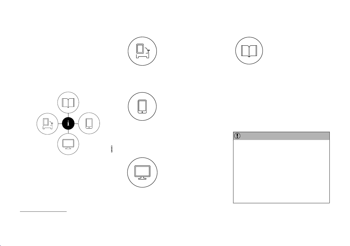
Owner's information is available in several different product formats, both digital and printed.
The owner's manual is available in the car's centre display, as a mobile app and on the Volvo
Cars support site. There is a Quick Guide and a
supplement to the owner's manual available in
the glovebox, with specifications and fuse information, amongst other things. A printed owner's
manual can be ordered.
The car's centre display
1
In the centre display, drag down
the top view and tap on
Owner's manual. Available
here are options for visual navigation with exterior and interior
images of the car. The information is searchable and is also
divided into categories.
Mobile app
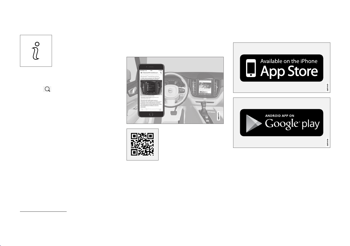
In App Store or Google Play,
search for "Volvo Manual",
download the app to your
smartphone or tablet and select
the car. Available in the app are
video tutorials and options for
visual navigation with exterior
and interior images of the car. It is easy to navigate between the different sections in the
owner's manual and the content is searchable.
Volvo Cars support site
Go to support.volvocars.com
and select your country. Here
you can find owner's manuals,
both online and in PDF format.
On the Volvo Cars support site
there are also video tutorials
help regarding your Volvo and your car ownership. The page is available for most markets.
and further information and
Printed information
There is a supplement to the
owner's manual1 in the glovebox that contains information
on fuses and specifications, as
well as a summary of important
and practical information.
There is also a Quick Guide available in printed
format that helps you to get started with the most
commonly used functions in the car.
Depending on equipment level selected, market,
etc. additional owner's information may also be
available in printed format in the car.
A printed owner's manual and associated supplement can be ordered. Contact a Volvo dealer to
order.
IMPORTANT
The driver is always responsible that the vehicle is driven safely in traffic and that applicable laws and regulations are followed. It is
also important that the car is maintained and
handled in accordance with Volvo's recommendations in the owner's information.
If there should be a difference between the
information in the centre display and the printed information then it is always the printed
information that applies.
1
A complete printed manual is included with the car for markets without owner's manual in the centre display.
16
Page 19
OWNER'S INFORMATION
NOTE
Changing the language in the centre display
may mean that some owner's information is
not compliant with national or local laws and
regulations. Do not switch to a language that
is difficult to understand as this may make it
difficult to find your way back through the
screen structure.
Related information
Owner's manual in centre display (p. 17)
•
Owner's Manual in mobile devices (p. 20)
•
Volvo Cars support site (p. 21)
•
Reading the owner's manual (p. 21)
•
Owner's manual in centre display
A digital2 version of the owner's manual is available in the car's centre display.
The digital owner's manual can be accessed from
the top view, and in some cases the contextual
owner's manual can also be accessed from the
top view.
NOTE
The digital owner's manual is not available
while driving.
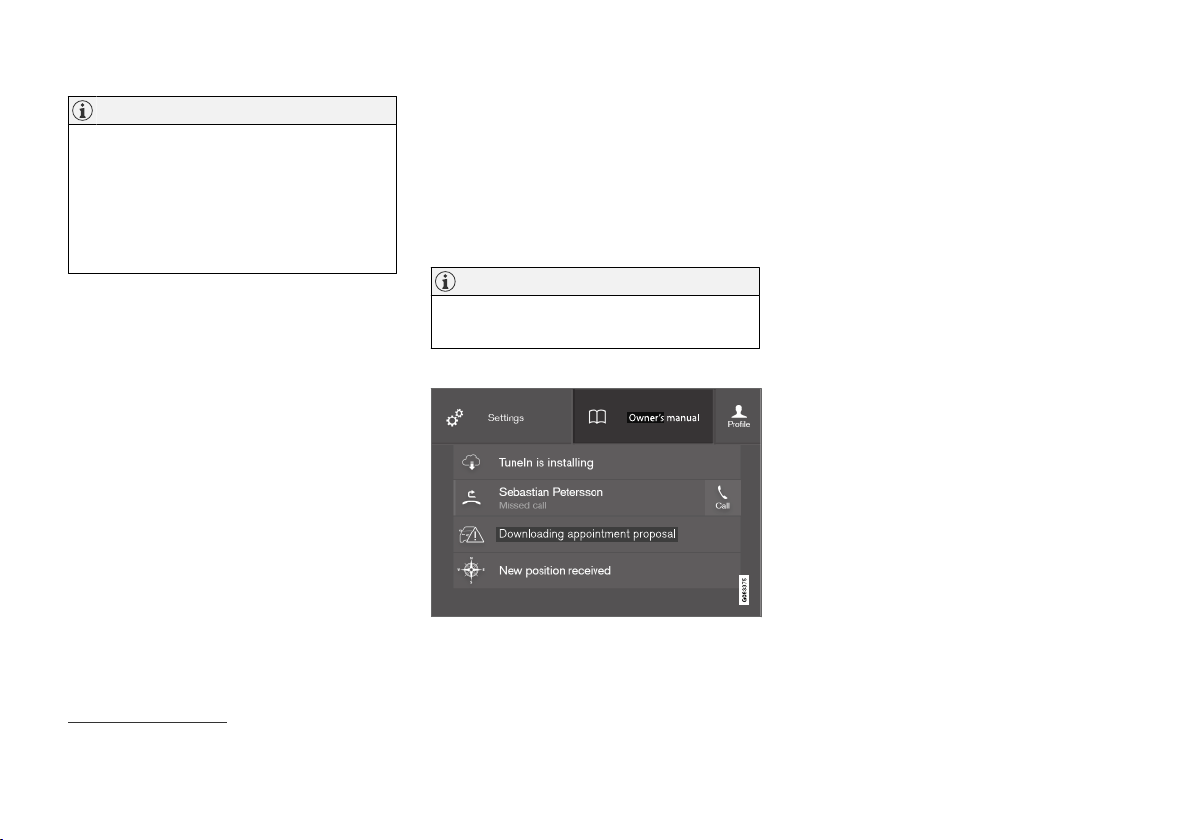
Owner's manual
Top view with button for owner's manual.
To open the owner's manual - drag down the top
view in the centre display and tap on
Owner's
manual.
The information in the owner's manual can be
accessed directly via the owner's manual homepage or its top menu.
2
Applies for most markets.
}}
17
Page 20
OWNER'S INFORMATION
||
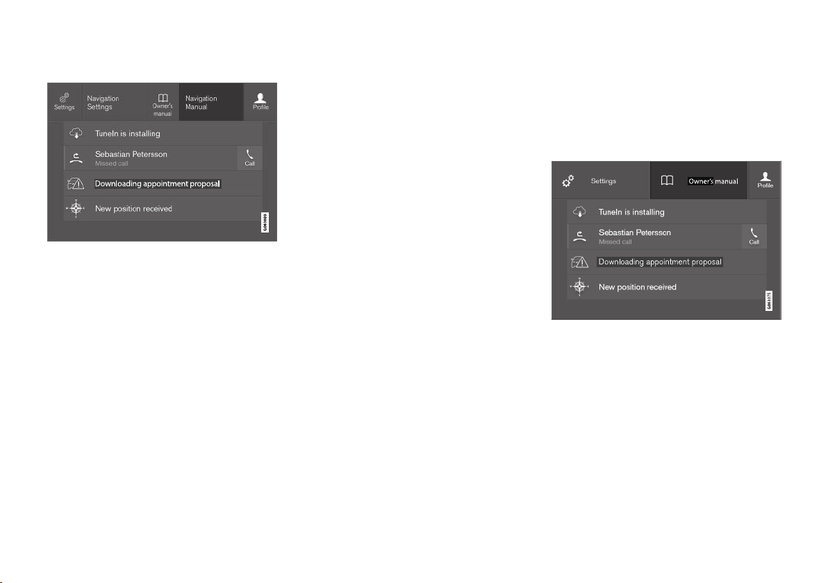
Contextual owner's manual
Top view with button for contextual owner's manual.
The contextual owner's manual is a shortcut to
an article in the owner's manual that describes
the active function shown on the screen. When
the contextual owner's manual is available, it is
shown to the right of
top view.
Tapping on the contextual owner's manual therefore opens an article in the owner's manual that
is related to the content that is shown on the
screen. E.g. tap on Navigation Manual – an article that is related to navigation opens.
This only applies to some of the apps in the car.
For downloaded third party apps, for example, it is
not possible to access app-specific articles.
Owner's manual in the
Related information
Navigate in the owner's manual in the centre
•
display (p. 18)
Navigating in the centre display's views
•
(p. 108)
Downloading apps (p. 501)
•
Navigate in the owner's manual in the centre display
The digital owner's manual can be accessed
from the centre display top view in the car. The
content is searchable and it is easy to navigate
between different sections.
The owner's manual is accessed from the top view.
To open the owner's manual - drag down the
–
top view in the centre display and tap on
Owner's manual.
There is a range of different options for finding
information in the owner's manual. The options
can be accessed from the owner's manual homepage and from the top menu.
18
Page 21
OWNER'S INFORMATION
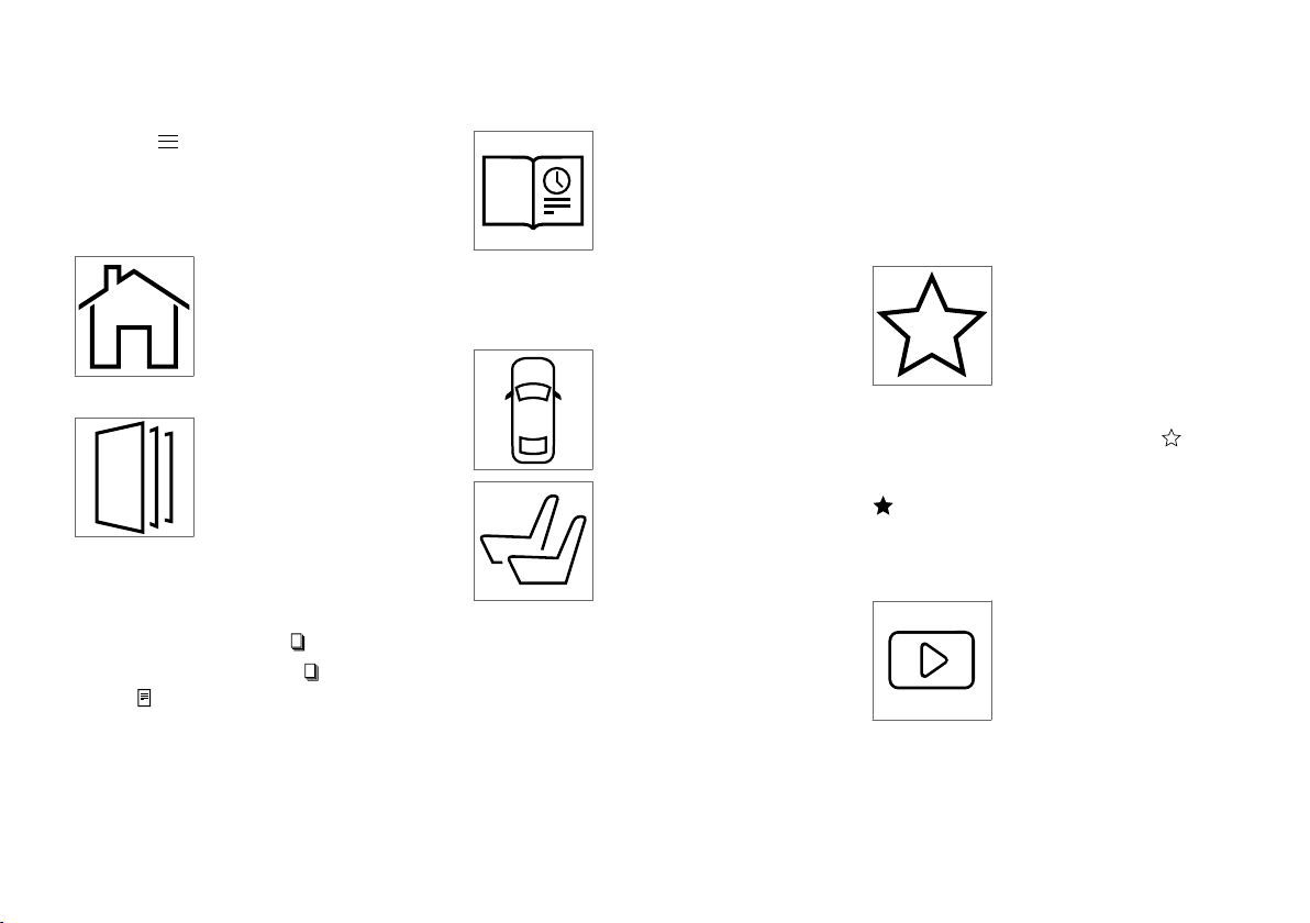
Opening the menu in the top menu
–
Press in the upper list in the owner's
manual.
> A menu with different options for finding
information is opened:
Homepage
Tap on the symbol to go back
to the start page in the owner's
manual.
Categories
The articles in the owner's
manual are structured into
main categories and subcategories. The same article can be
found in several appropriate
categories so that it can be
found more easily.
1.
Press
Categories.
> The main categories are shown in a list.
Tap on a main category (
2.
>
A list of subcategories (
) is shown.
(
3. Tap on an article to open it.
To go back, press the back arrow.
).
) and articles
Quick Guide
Press the symbol to access a
page with links to a selection of
articles that can be particularly
useful to read in order to get to
know the most common functions of the car. The articles
gories, but are collected here for quick access.
Tap on an article in order to read it in its entirety.
Hotspots for exterior and interior
1.
Press
> Exterior or interior images are shown with
so-called hotspots in place. The hotspot
leads to articles about the corresponding
part of the car. Swipe horizontally over the
screen to browse among the images.
can also be accessed via cate-
Exterior and interior overview
images of the car. Different
parts are designated with hotspots that lead to articles about
those parts of the car.
Exterior or Interior.
2. Tap on a hotspot.
> The title of the article about the area is
shown.
3. Tap on the title to open the article.
To go back, press the back arrow.
Favourites
Press the symbol to access the
articles saved as favourites. Tap
on an article in order to read it
in its entirety.
Saving or deleting articles as favourites
Save an article as favourite by pressing at the
top right when an article is open. When an article
has been saved as a favourite the star is filled in:
.
To remove an article as a favourite, press the star
again in the current article.
Video
Press the symbol to view brief
instruction videos for various
functions in the car.
}}
19
Page 22
OWNER'S INFORMATION
||
Information
Tap on the symbol to obtain
information about which version
of the owner's manual is available in the car as well as other
useful information.
Using the search function in the top menu
Tap on in the top menu of the owner's
1.
manual. A keyboard appears in the lower part
of the screen.
2. Type in a keyword, such as "seatbelt".
> Suggestions for articles and categories
are shown while letters are being entered.
3. Tap on the article or category to access it.
Related information
Owner's manual in centre display (p. 17)
•
Keyboard in centre display (p. 119)
•
Reading the owner's manual (p. 21)
•
Owner's Manual in mobile devices
The owner's manual is available as a mobile
app3 from both the App Store and Google Play.
The app is adapted for smartphones and tablets.
The owner's manual can be
downloaded as a mobile app
from the App Store or Google
Play. The QR code provided
here takes you directly to the
app. Alternatively, you can
search for "Volvo manual" in
the App Store or Google Play.
The app contains a video along with exterior and
interior images where different parts of the car
are highlighted with so-called hotspots, which
lead to articles about the area in question. It is
easy to navigate between the different sections
in the owner's manual and the content is searchable.
The mobile app is available from both the App Store and
Google Play.
Related information
Reading the owner's manual (p. 21)
•
3
For certain mobile devices.
20
Page 23

OWNER'S INFORMATION
Volvo Cars support site
More information on your car is available on the
Volvo Cars website and support site.
Support on the Internet
Go to support.volvocars.com to visit the site. The
support site is available for most markets.
It contains support for functions such as webbased services and functions, Volvo On Call*, the
navigation system* and apps. Videos and stepby-step instructions explain different procedures,
e.g. how to connect the car to the Internet via a
mobile phone.
Downloadable information
Maps
For cars equipped with Sensus Navigation there
is the facility to download maps from the support
page.
Owner's manuals as PDF
Owner's manuals are available for download in
PDF format. Select car model and model year to
download the manual as required.
Contact
The support site contains contact details to customer support and your nearest Volvo retailer.
Log in to Volvo Cars website
Create a personal Volvo ID and log in to
www.volvocars.com. When you have logged in it is
possible to get an overview of service, agree-
ments and warranties, amongst other things.
Here there is also information about accessories
and software adapted for your car model.
Related information
Volvo ID (p. 26)
•
Reading the owner's manual
A good way of getting to know your new car is
to read the owner's manual, ideally before your
first journey.
Reading the owner's manual is a good way to
become familiar with new functions, get advice
on how best to handle the car in different situations and learn how to make the best use of all
the car's features. Please pay attention to the
safety instructions contained in the owner's manual.
The intention of this owner's information is to
explain all possible functions, options and accessories included in a Volvo vehicle. It is not
intended as an indication or guarantee that all of
these features, functions and options are
included in every vehicle. Some terminology used
may not exactly match terminology used in sales,
marketing and advertising materials.
Development work is constantly underway in
order to improve our product. Modifications may
mean that information, descriptions and illustrations in the owner's manual differ from the equipment in the car. We reserve the right to make
modifications without prior notice.
Do not remove this manual from the car - if problems should arise then the necessary information
about where and how to seek professional help
will be missing.
© Volvo Car Corporation
}}
* Option/accessory.
21
Page 24
OWNER'S INFORMATION
||
Options/accessories
In addition to standard equipment, the owner's
manual also describes options (factory fitted
equipment) and certain accessories (retrofitted
extra equipment).
All, at the time of publication known, options and
accessories are marked with an asterisk: *.
The equipment described in the owner's manual
is not available in all cars - they have different
equipment depending on adaptations for the
needs of different markets and national or local
laws and regulations.
In the event of uncertainty over what is standard
or an option/accessory, contact a Volvo dealer.
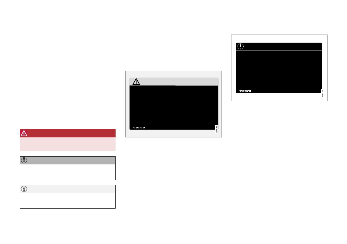
Special texts
WARNING
Warning texts appear if there is a risk of
injury.
IMPORTANT
"Important" texts appear if there is a risk of
damage.
NOTE
NOTE texts give advice or tips that facilitate
the use of e.g. features and functions.
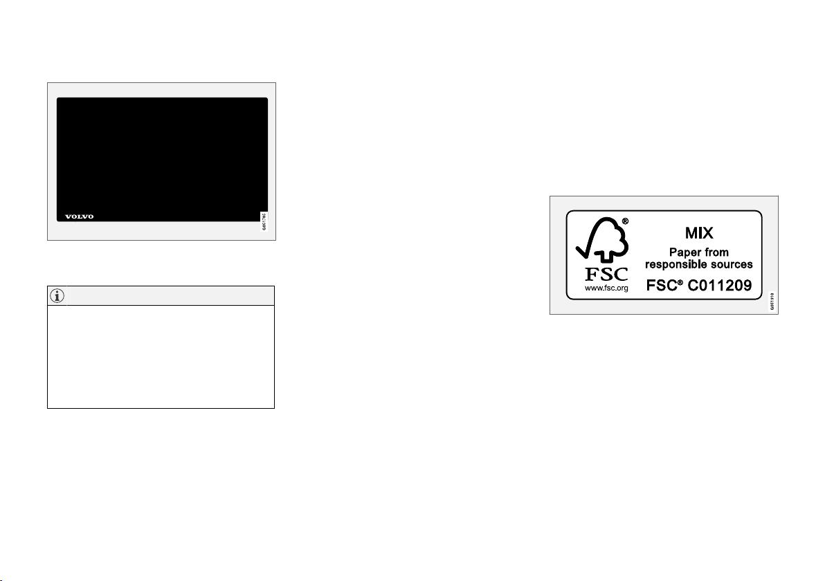
Decals
The car contains different types of decal which
are designed to convey important information in a
simple and clear manner. The decals in the car
have the following descending degree of importance for the warning/information.
Warning of personal injury
Black ISO symbols on yellow warning field, white
text/image on black message field. Used to indicate the presence of danger which, if the warning
is ignored, may result in serious personal injury or
fatality.
Risk of property damage
White ISO symbols and white text/image on
black or blue warning field and message field.
Used to indicate the presence of danger which, if
the warning is ignored, may result in damage to
property.
22
* Option/accessory.
Page 25
OWNER'S INFORMATION
Information
White ISO symbols and white text/image on
black message field.
NOTE
It is not intended that the decals illustrated in
the owner's manual should be exact replicas
of those in the car. They are included to show
their approximate appearance and location in
the car. The information that applies to your
particular car is available on the respective
decals for your car.
Illustrations and video clips
Illustrations and video clips used in the owner's
manual are sometimes schematic and are
intended to provide an overall picture or example
of a certain function. They may deviate from the
car's appearance depending on equipment level
and market.
Related information
Owner's manual in centre display (p. 17)
•
Owner's Manual in mobile devices (p. 20)
•
Volvo Cars support site (p. 21)
•
The owner's manual and the environment
The Owner's Manual is printed on paper originating from controlled forests.
The Forest Stewardship Council (FSC)® symbol
shows that the paper pulp in a printed owner's
manual comes from FSC®-certified forests or
other controlled sources.
Related information
Drive-E - cleaner driving pleasure (p. 28)
•
23
Page 26

Page 27

YOUR VOLVO
Page 28
YOUR VOLVO
Volvo ID
Volvo ID is a personal ID that gives access to a
wide range of services via a single username
and password.
NOTE
The services available may vary over time and
depend on equipment level and market.
Examples of services:
Volvo On Call app* – check the car with your
•
phone. For example, you can check fuel level,
show the nearest petrol station and lock the
car remotely.
Send to Car – send addresses from map
•
services on the Web, directly to the car.
Book service and repair – register your pre-
•
ferred workshop/dealer on volvocars.com
and book service directly from the car.
NOTE
If the username/password for a service (e.g.
Volvo On Call) is changed, then it is also
changed automatically for other services.
Volvo ID is created from the car, volvocars.com or
the Volvo On Call app1.
When a Volvo ID is registered in the car, several
services will be made available. Several Volvo IDs
can be used for the same car and several cars
can even be connected to the same Volvo ID.
Related information
Creating and registering a Volvo ID (p. 26)
•
Book service and repair (p. 601)
•
Creating and registering a Volvo ID
It is possible to create a Volvo ID in different
ways. If the Volvo ID is created at volvocars.com
or with Volvo On Call app2, the Volvo ID must
also be registered to the car to enable use of the
various Volvo ID services.
Create a Volvo ID with the Volvo ID app
1.
Download the Volvo ID app from
Centre in the centre display's app view.
2. Start the app and register a personal email
address.
3. Follow the instructions that are automatically
sent to the specified email address.
> A Volvo ID has now been created and
automatically registered to the car.
Volvo ID services can now be used.
Download
1
If you have Volvo On Call*.
2
Only applies to certain markets.
26
* Option/accessory.
Page 29
YOUR VOLVO
Create a Volvo ID on the Volvo Cars website
1. Go into www.volvocars.com and log in3 using
the icon at the top right. Select Create Volvo
ID.
2. Enter a personal email address.
3. Follow the instructions that are automatically
sent to the specified email address.
> A Volvo ID has now been created. Read
below to learn how to register the ID to
the car.
Create a Volvo ID with the Volvo On Call
4
app
1. Download the latest version of the Volvo On
Call app from a smartphone, via e.g. App
Store, Windows Phone or Google Play.
2. Choose to create a Volvo ID from the app's
start page and enter a personal email
address.
3. Follow the instructions that are automatically
sent to the specified email address.
> A Volvo ID has now been created. Read
below to learn how to register the ID to
the car.
Registering your Volvo ID to the car
If you created your Volvo ID via the web or the
Volvo On Call app, register it to your car as follows:
1. If not done already, download the Volvo ID
app from
Download Centre in the centre
display's app view.
NOTE
To download apps, the car must be connected to the Internet.
2. Start the app and enter your Volvo ID/your
email address.
3. Follow the instructions that are automatically
sent to the email address linked to your
Volvo ID.
> Your Volvo ID is now registered to the car.
Volvo ID services can now be used.
Related information
Volvo ID (p. 26)
•
Downloading apps (p. 501)
•
Managing system updates via the Download
•
Centre (p. 599)
Internet-connected car* (p. 533)
•
3
Available on certain markets.
4
Cars with Volvo On Call*.
* Option/accessory.
27
Page 30

YOUR VOLVO
Drive-E - cleaner driving pleasure
Volvo Car Corporation is constantly working on
the development of safer and more efficient
Environmental care is one of Volvo Cars’ core values and influences all operations. The environmental work is based on the whole life cycle of
the car and takes into account the environmental
impact it has, from design to scrapping and recycling. Volvo Cars' basic principle is that every new
product developed must have less impact on the
environment than the product it replaces.
Volvo's environmental management work has
resulted in the development of more effective
and less polluting drivelines Drive-E. Personal
environment is also important to Volvo - the air
products and solutions in order to reduce the
negative impact on the environment.
inside a Volvo is, for example, cleaner than the air
outside thanks to the climate control system.
Your Volvo complies with stringent international
environmental standards. All Volvo's manufacturing units must be ISO 14001 certified, and this
supports a systematic approach to the operation's environmental issues, which leads to continuous improvement with reduced environmental
impact. Holding the ISO certificate also means
that environmental laws and regulations in force
are complied with. Volvo also requires that its
partners must also meet these requirements.
Fuel consumption
Since a large part of a car's total environmental
impact stems from its use, the emphasis of Volvo
Cars' environmental work is on reducing fuel consumption, carbon dioxide emissions and other air
pollutants. Volvo cars have competitive fuel consumption in each of their respective classes.
Lower fuel consumption generally results in lower
emission of the greenhouse gas, carbon dioxide.
28
Page 31

YOUR VOLVO
Contributing to a better environment
An energy-efficient and fuel-efficient car not only
contributes to a reduced impact on the environment, but also means reduced costs for the
owner of the car. As the driver, it is easy to
reduce fuel consumption and thereby save
money and contribute to a better environment here is some advice:
Plan for an effective average speed. Speeds
•
above approx. 80 km/h (approx. 50 mph)
and below 50 km/h (approx. 30 mph) lead to
increased energy consumption.
Follow the Service and Warranty Booklet's
•
recommended intervals for service and maintenance of the car.
Avoid letting the engine idle - switch off the
•
engine when stationary for longer periods.
Pay attention to local regulations.
Plan the journey - a lot of unnecessary stops
•
and uneven speed contribute to increased
fuel consumption.
Use preconditioning - it improves the range
•
of the hybrid battery and reduces the energy
requirement while driving.
Also remember to always dispose of environmentally hazardous waste, such as batteries and oil, in
an environmentally safe manner. Consult a workshop in the event of uncertainty about how this
type of waste should be discarded - an authorised Volvo workshop is recommended.
Efficient emission control
Your Volvo is manufactured following the concept
"Clean inside and out" – a concept that encompasses a clean interior environment as well as
highly efficient emission control. In many cases
the exhaust emissions are well below the applicable standards.
Clean air in the passenger compartment
An air filter helps prevent dust and pollen entering the passenger compartment via the air intake.
The Interior Air Quality System (IAQS)* ensures
that the incoming air is cleaner than the air in the
traffic outside.
The system cleans the air in the passenger compartment from contaminants such as particles,
hydrocarbons, nitrous oxides and ground-level
ozone. If the outside air is contaminated then the
air intake is closed and the air is recirculated.
Such a situation may arise in heavy traffic,
queues and tunnels for example.
IAQS is a part of the Clean Zone Interior Package (CZIP)*, which also includes a function that
allows the fan to start when the car is unlocked
with the remote control key.
Interior
The material used in the interior of a Volvo is
carefully selected and has been tested in order to
be pleasant and comfortable. Some of the details
are hand-made, such as the seams of the steer-
ing wheel that are sewn by hand. The interior is
monitored in order not to emit strong odours or
substances that cause discomfort in the event of
e.g. high heat and bright light.
Volvo workshops and the environment
Regular maintenance creates the conditions for a
long service life and low fuel consumption for
your car. In this way you also contribute to a
cleaner environment. When Volvo's workshops
are entrusted with the service and maintenance
of your car it becomes part of Volvo's system.
Volvo makes clear demands regarding the way in
which workshop premises shall be designed in
order to prevent spills and discharges into the
environment. The workshop staff have the knowledge and the tools required to guarantee good
environmental care.
Recycling
Since Volvo works from a life cycle perspective, it
is also important that the car is recycled in an
environmentally sound manner. Almost all of the
car can be recycled. The last owner of the car is
therefore requested to contact a retailer for referral to a certified/approved recycling facility.
Related information
Fuel consumption and CO2 emissions
•
(p. 666)
Economical driving (p. 466)
•
Start and switch off preconditioning (p. 218)
•
}}
* Option/accessory.
29
Page 32

YOUR VOLVO
||
The owner's manual and the environment
•
(p. 23)
Air quality (p. 196)
•
30
Page 33
YOUR VOLVO
IntelliSafe – driver support and safety
IntelliSafe is the Volvo Cars concept for car
safety. IntelliSafe comprises a number of systems5, whose purpose is to make a car journey
safer, to prevent injuries and to protect passengers and other road users.
WARNING
The functions are supplementary aids - they
cannot handle all situations in all conditions.
The driver always bears responsibility that the
vehicle is driven safely and that applicable
road traffic rules and regulations are followed.
Support
With the aim of assisting the driver to drive the
car in a safer way, IntelliSafe has the following
functions.
Active main beam
•
Tunnel detection
•
Pilot Assist
•
Cross Traffic Alert
•
Blind Spot Information
•
Park Assist*
•
Park Assist Pilot*
•
Park assist camera*
•
Road Sign Information*
•
Electronic stability control
•
Roll Stability Control
•
Speed limiter*
•
Cruise control
•
Adaptive cruise control*
•
Rear Collision Warning
•
Driver Alert Control
•
All-wheel drive
•
6
Prevention
With the aim of assisting the driver to avoid an
accident, IntelliSafe has the following functions.
City Safety
•
Distance Warning*
•
Lane assistance
•
Collision Avoid. Assistance
•
Protection
With the aim of protecting the driver and passengers in certain situations in the event of an accident, IntelliSafe has the following collaborative
functions.
Whiplash Protection System
•
Seatbelts with seatbelt tensioners
•
Airbags
•
NOTE
Read the individual sections on each system
in order to fully understand the functions and
learn about important warnings.
Related information
Active main beam (p. 148)
•
Safety (p. 42)
•
Driving support systems (p. 278)
•
5
Some of the systems are fitted as standard, while others are options. This may vary depending on market, model year and car model.
6
All Wheel Drive
* Option/accessory.
31
Page 34
YOUR VOLVO
Sensus - online connectivity and entertainment
Sensus makes it possible to use different types
of apps and turn the car into a Wi-Fi hotspot.
This is Sensus
Sensus offers an intelligent interface and online
connectivity with the digital world. An intuitive
navigation structure makes it possible to receive
relevant support, information and entertainment
when it is necessary, without distracting the
driver.
Sensus covers all solutions in the car that are
connected with entertainment, online connectivity, navigation* and the user interface between
driver and car. It is Sensus that makes communication possible between you, the car and the outside world.
Information when it is needed, where it is needed
The different displays in the car provide information at the right time. The information is shown in
different locations based on how it should be prioritised by the driver.
32
* Option/accessory.
Page 35
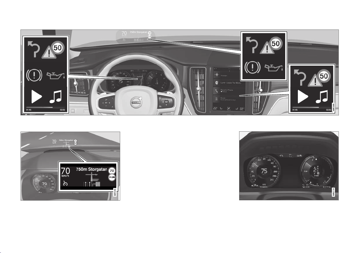
Different types of information are shown in different displays depending on how the information should be prioritised.
Head-up display*
traffic warnings, speed information and navigation* information. Road Sign Information and
incoming phone calls are also shown in the headup display. The display is operated via the righthand steering wheel keypad and via the centre
display.
YOUR VOLVO
Driver display
The head-up display shows selected information
that the driver should deal with as soon as possible. Such information may, for example, include
The driver display shows information on speed
and e.g. incoming calls or song tracks being
* Option/accessory.
}}
33
Page 36
YOUR VOLVO
played. The display is operated via the two steer-
||
ing wheel keypads.
Centre display
Many of the main functions of the car are controlled from the centre display, a touch screen
which reacts to touch. The number of physical
buttons and controls in the car is therefore minimal. The screen can even be operated while
wearing gloves.
From here, for example, you can control the climate control system, the entertainment system
and seat position*. The information that is shown
in the centre display can be acted on by the
driver or someone else in the car when the
opportunity arises.
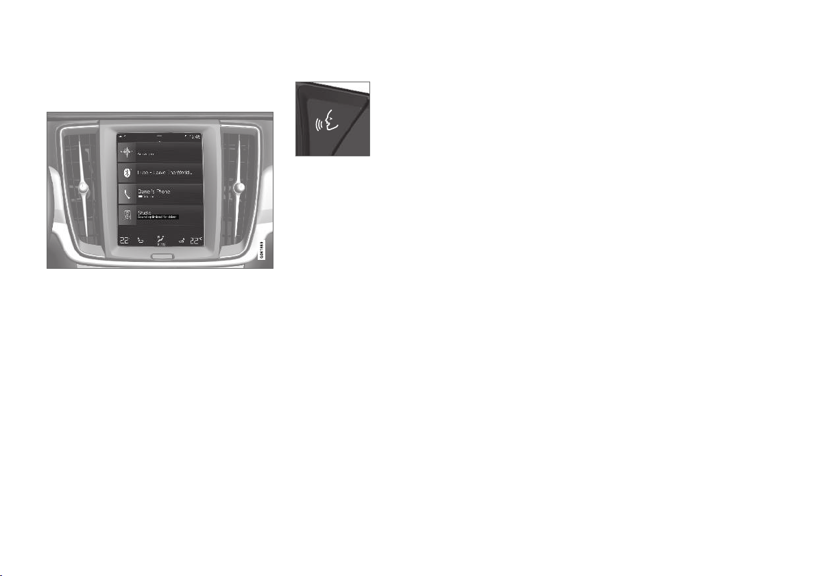
Voice recognition system
The voice recognition system
can be used without the driver
needing to take his/her hands
off the steering wheel. The system can understand natural
speech. Use voice recognition
song, call someone, increase the temperature or
read out a text message.
to, for example, play back a
Related information
Head-up display* (p. 135)
•
Driver display (p. 77)
•
Overview of centre display (p. 102)
•
Voice recognition (p. 138)
•
Internet-connected car* (p. 533)
•
Sharing Internet access from the car via a
•
Wi-Fi hotspot (p. 537)
34
* Option/accessory.
Page 37
YOUR VOLVO
Software updates
So that you as a Volvo customer get the best
experience of your car, Volvo continuously develops the systems in the cars and the services that
you are offered.
You can update the software in your Volvo to the
latest version when your car is serviced at an
authorised Volvo dealer. The latest software
update allows you to benefit from available
improvements, including improvements from earlier software updates.
For more information about released updates and
answers to frequently asked questions, please go
to support.volvocars.com.
NOTE
Functionality after updating may vary depending on market, model, model year and options.
Related information
Sensus - online connectivity and entertain-
•
ment (p. 32)
Managing system updates via the Download
•
Centre (p. 599)
Recording data
As part of Volvo's safety and quality assurance,
certain information about the vehicle's operation,
functionality and incidents are recorded in the
car.
This vehicle is equipped with an "Event Data
Recorder" (EDR). Its primary purpose is to register and record data related to traffic accidents or
collision-like situations, such as times when the
airbag deploys or the vehicle strikes an obstacle
in the road. The data is recorded in order to
increase understanding of how vehicle systems
work in these types of situations. The EDR is
designed to record data related to vehicle
dynamics and safety systems for a short time,
usually 30 seconds or less.
The EDR in this vehicle is designed to record
data related to the following in the event of traffic
accidents or collision-like situations:
How the various systems in the car worked
•
Whether the driver and passenger seatbelts
•
were fastened/tensioned
The driver's use of the accelerator or brake
•
pedal
The travel speed of the vehicle
•
This information can help us better understand
the circumstances in which traffic accidents, injuries and damage occur. The EDR only records
data when a non-trivial collision situation occurs.
The EDR does not record any data during normal
driving conditions. Similarly, the system never
registers who is driving the vehicle or the geographic location of the accident or near-miss situation. However, other parties, such as the police,
could use the recorded data in combination with
the type of personally identifiable information
routinely collected after a traffic accident. Special
equipment and access to either the vehicle or the
EDR is required to be able to interpret the registered data.
In addition to the EDR, the car is equipped with a
number of computers designed to continually
check and monitor the function of the car. They
can record data during normal driving conditions,
but in particular register faults affecting the vehicle's operation and functionality, or upon activation of the vehicle's driver support function (e.g.
City Safety and the auto brake function).
Some of the recorded data is required to enable
service and maintenance technicians to diagnose
and remedy any faults that occurred in the vehicle. The registered information is also needed to
enable Volvo to satisfy legal requirements laid out
in laws and by government authorities. Information registered in the vehicle is stored in its computer until the vehicle is serviced or repaired.
In addition to the above, the registered information can be used in aggregate form for research
and product development with the aim of continuously improving the safety and quality of Volvo
cars.
}}
35
Page 38

YOUR VOLVO
Volvo will not contribute to the above-described
information being disclosed to third parties without the vehicle owner's consent. To comply with
national legislation and regulations, Volvo may be
forced to disclose information of this nature to
the police or other authorities who may assert a
legal right to access such. Special technical
equipment which Volvo and workshops that have
entered into agreements with Volvo have access
to is required to be able to read and interpret the
recorded data. Volvo is responsible that the information, which is transferred to Volvo during servicing and maintenance, is securely stored and
managed and that its management complies with
relevant legal requirements. For further information - contact a Volvo retailer.
Terms & Conditions for Services
Volvo offers services so that you can drive your
Volvo as safely and as comfortably as possible.
These services include everything from assistance in emergencies to navigation and various
maintenance services.
Before using the services, it is important for you
to read the Terms & Conditions for Services at
support.volvocars.com.
Related information
Customer Privacy Policy (p. 36)
•
Customer Privacy Policy
Volvo respects and safeguards the personal
integrity of everyone visiting our website.
This policy regards to the handling of customer
data and personal information. The purpose is to
give current, past and potential customers a general understanding of:
The circumstances in which we gather and
•
process your personal data.
The types of personal data we gather.
•
The reason we gather your personal data.
•
How we handle your personal data.
•
This policy can be read in its entirety at
support.volvocars.com.
Related information
User terms and conditions and data sharing
•
(p. 539)
Terms & Conditions for Services (p. 36)
•
Recording data (p. 35)
•
36
Page 39

YOUR VOLVO
Important information on accessories and auxiliary equipment
The incorrect connection and installation of
accessories and extra equipment can negatively
affect the car's electronic system.
We strongly recommend that Volvo owners only
install Volvo approved original accessories, and
that installation of accessories is only carried out
by trained and qualified Volvo service technicians.
Certain accessories only function when associated software is installed in the car's computer
system.
The equipment described in the owner's manual
is not available in all cars - they have different
equipment depending on adaptations for the
needs of different markets and national or local
laws and regulations.
Options or accessories described in this manual
are marked with an asterisk. In the event of
uncertainty over what is standard or an option/
accessory, contact a Volvo retailer.
WARNING
The driver always bears the ultimate responsibility that the car is used safely and that laws
and regulations in force are followed.
It is also important that the car has maintenance and service according to Volvo's recommendations, the owner's information and
the service and warranty booklet.
If the on-board information differs from the
printed owner's manual then the printed information always has precedence.
Related information
Installation of accessories (p. 37)
•
Connection of equipment to the car's diag-
•
nostic socket (p. 38)
Reading the owner's manual (p. 21)
•
Installation of accessories
We strongly recommend that Volvo owners only
install Volvo approved original accessories, and
that installation of accessories is only carried out
by trained and qualified Volvo service technicians. Certain accessories only function when
associated software is installed in the car's computer system.
Volvo original accessories are tested to
•
ensure that they function with the car systems for performance, safety and emissions
control. In addition, a trained and qualified
Volvo service technician knows where accessories may or may not be safely installed in
your Volvo. Always seek the advice of a
trained and qualified Volvo service technician
before installing any accessories in or on
your car.
Accessories that are not approved by Volvo
•
may not have been specifically tested for use
with your car.
Some of the car's performance or safety sys-
•
tems can be negatively affected if you install
accessories that have not been tested by
Volvo, or if you permit someone without
experience of the car to install accessories.
Damage that is caused by accessories instal-
•
led in a non-approved or incorrect way is not
covered by any new car warranty. More warranty information can be found in the service
and warranty booklet. Volvo does not accept
}}
37
Page 40
YOUR VOLVO
||
any liability for deaths, personal injury or
costs arising as a result of the installation of
non-original accessories.
Related information
Important information on accessories and
•
auxiliary equipment (p. 37)
Connection of equipment to the car's diagnostic socket
Incorrect connection and installation of software
or diagnostic tools may have a negative effect on
the car's electronic system.
We strongly recommend that Volvo owners only
install Volvo approved original accessories, and
that installation of accessories is only carried out
by trained and qualified Volvo service technicians.
Certain accessories only function when associated software is installed in the car's computer
system.
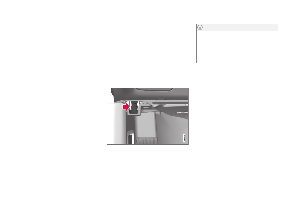
Data link connector (On-board Diagnostic, OBDII) is
under the instrument panel on the driver's side.
NOTE
Volvo Cars accepts no liability for the consequences if unauthorised equipment is connected to the On-board Diagnostic socket
(OBDII). This socket should only be used by
trained and qualified Volvo service technicians.
Related information
Important information on accessories and
•
auxiliary equipment (p. 37)
38
Page 41
YOUR VOLVO
Showing the car's identification number
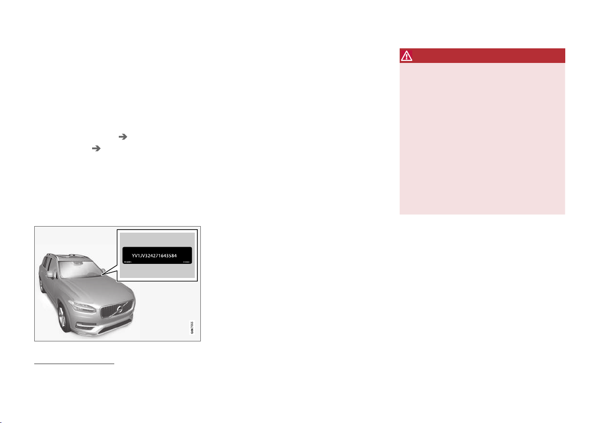
When contacting a Volvo dealer concerning your
Volvo On Call subscription, for example, you will
need the car's identification number (VIN7).
1.
2. Continue to
Another way of finding the VIN is to look on the
dashboard through the car's windscreen, on the
first page of the service and warranty booklet or
in the car's registration certificate.
Settings in the top view in the centre
Press
display.
System System
Information
Number
> The car's identification number is shown.
Vehicle Identification
.
Driver distraction
The driver is responsible for doing everything
possible to ensure the safety of themselves, their
passengers and other road users. Part of this
responsibility is avoiding distractions such as
carrying out an activity that is not related to operating the car in a driving environment.
Your new Volvo is, or can be, equipped with content-rich entertainment and communications systems. This could be mobile phones with handsfree, navigation systems and audio systems with
lots of functions. You may also have other portable electronic devices for your own convenience.
Used correctly, in a safe way they can enrich the
driving experience. If they are used in the wrong
way they could distract you.
We wish to give the following warnings regarding
such systems, to indicate Volvo's concern for
your safety. Never use a device or function in the
car in such a way that it will distract you from the
task of driving safely. Distractions can lead to
serious accidents. Apart from these general
warnings, we offer the following advice regarding
the new functions that may be in the car:
WARNING
Never use a hand-held mobile phone
•
while driving. In some areas it is forbidden
for the driver to use a mobile phone while
the car is moving.
If the car is equipped with a navigation
•
system you must only set and change the
itinerary when the car is parked.
Never program the audio system while
•
the car is moving. Program the radio's
presets when the car is parked and then
use the programmed presets for faster
and simpler use of the radio.
Never use laptops or hand-held comput-
•
ers while the car is moving.
Related information
Sound, media and Internet (p. 498)
•
VIN is positioned in a similar place on all models.
7
Vehicle Identification Number
39
Page 42

Page 43

SAFETY
Page 44
SAFETY
Safety
The vehicle is equipped with several safety systems that work together to protect the vehicle's
driver and passengers in the event of an accident.
The car is equipped with a number of sensors
that react in the event of an accident and activate
different safety systems, such as different types
of airbags and seatbelt tensioners. Depending on
the specific accident situation, such as collisions
at different angles, roll-over or driving off the
road, the systems react in different ways to provide the best protection.
There are also mechanical safety systems such
as Whiplash Protection System. The car is also
constructed so that a large part of the force of a
collision is distributed to beams, pillars, floor, roof
and other parts of the body.
The car's safety mode may be activated after a
collision if an important function in the car has
been damaged.
Warning symbol in driver display
The warning symbol is illuminated in
the driver display when the car's electrical system is set in ignition position
II. The symbol is extinguished after
approx. 6 seconds if the car's safety system is
fault-free.
WARNING
If the warning symbol remains illuminated or
is switched on during driving and the mes-
SRS airbag Service urgent Drive to
sage
workshop is shown in the driver display, it
means that part of one of the safety systems
does not have full functionality. Volvo recommends that an authorised Volvo workshop
should be contacted as soon as possible.
WARNING
Never modify or repair the car's various safety
systems yourself. Defective work in one of the
systems can cause malfunction and result in
serious personal injury. Volvo recommends
that an authorised Volvo workshop should be
contacted.
If the specific warning symbol is broken
then the general warning symbol is illuminated instead and the driver display
shows the same message.
Related information
Safety during pregnancy (p. 42)
•
Seatbelts (p. 44)
•
Airbags (p. 49)
•
Whiplash Protection System (p. 43)
•
Safety mode (p. 56)
•
Child safety (p. 57)
•
Safety during pregnancy
It is important that the seatbelt is used correctly
during pregnancy, and that pregnant drivers
adjust their seating position.
Seatbelt
The diagonal section should wrap over the shoulder then be routed between the breasts and to
the side of the abdomen.
The lap section should lay flat over the thighs and
as low as possible under the abdomen. – It must
never be allowed to ride upward. Remove the
slack from the seatbelt and ensure that it fits as
close to the body as possible. In addition, check
that there are no twists in the seatbelt.
Seating position
As the pregnancy progresses, pregnant drivers
must adjust the seat and steering wheel such
that they can easily maintain control of the vehi-
42
Page 45
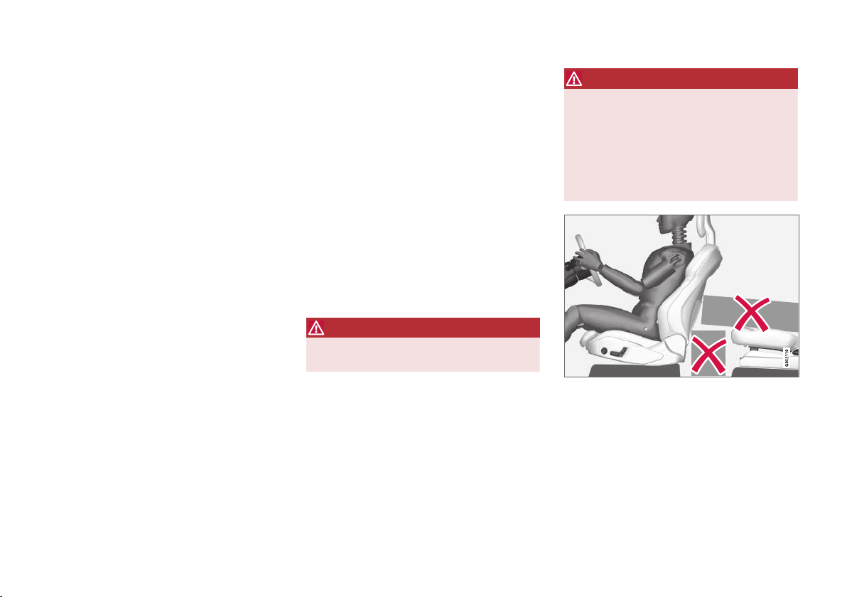
SAFETY
cle as they drive (which means that they must be
able to easily operate the foot pedals and steering wheel). The aim should be to position the
seat with as large a distance as possible between
abdomen and steering wheel.
Related information
Safety (p. 42)
•
Seatbelts (p. 44)
•
Manual front seat (p. 176)
•
Power* front seat (p. 177)
•
Whiplash Protection System
Whiplash Protection System (WHIPS) reduces
the risk of whiplash injuries. The system consists
of energy absorbing backrests and seat cushion,
as well as a specially designed head restraint in
the front seats.
WHIPS is deployed in the event of a rear-end
collision, where the angle and speed of the collision and the nature of the colliding vehicle all
have an influence.
When WHIPS is deployed, the front seat backrests are lowered backward and the seat cushions move downward to change the seating position of the driver and front seat passenger. Its
movement helps to absorb some of the forces
that can arise and cause whiplash.
WARNING
WHIPS is a supplement to the seatbelts.
Always use a seatbelt.
WARNING
Never modify or repair the seat or WHIPS
yourself. Volvo recommends that an authorised Volvo workshop should be contacted.
If the front seats have been subjected to a
major load, such as in conjunction with a collision, the seats must be replaced. Some of the
seats' protective properties may have been
lost even if they do not appear damaged.
Do not leave any objects on the floor behind or under
the front seats or in the rear seat that may prevent
WHIPS from functioning.
* Option/accessory.
}}
43
Page 46
SAFETY
||
WARNING
Do not squeeze rigid objects between the
rear seat cushion and the front seat's backrest.
If a backrest in the rear seat is lowered then
any load must be secured to prevent it from
sliding up to the front seat backrest in the
event of a collision.
WARNING
If a backrest in the rear seat is lowered or a
rear-facing child seat is used in the rear seat,
the corresponding front seat must be moved
forward so that it does not make contact with
the lowered backrest or child seat.
Seating position
For optimum protection from WHIPS the driver
and passenger must have the correct seating
position and make sure that the system's function is not obstructed.
Set the correct seating position in the front seat
before driving starts.
Driver and front seat passenger should sit in the
centre of the seat with as little space as possible
between the head and the head restraint.
WHIPS and child seats
The protection provided by the car to children
seated in a child seat or on a booster cushion is
not diminished by WHIPS.
Related information
Safety (p. 42)
•
Manual front seat (p. 176)
•
Power* front seat (p. 177)
•
Rear Collision Warning (p. 349)
•
Seatbelts
Heavy braking can have serious consequences
if the seatbelts are not used.
It is important that the seatbelt lies against the
body so it can provide maximum protection. Do
not lean the backrest too far back. The seatbelt is
designed to protect in a normal seating position.
WARNING
Remember not to clip or hook the seatbelt to
hooks or other interior fittings, as this prevents the belt from tightening properly.
WARNING
The seatbelts and airbags interact. If a seatbelt is not used or is used incorrectly, this may
diminish the protection provided by the airbag
in the event of a collision.
44
* Option/accessory.
Page 47
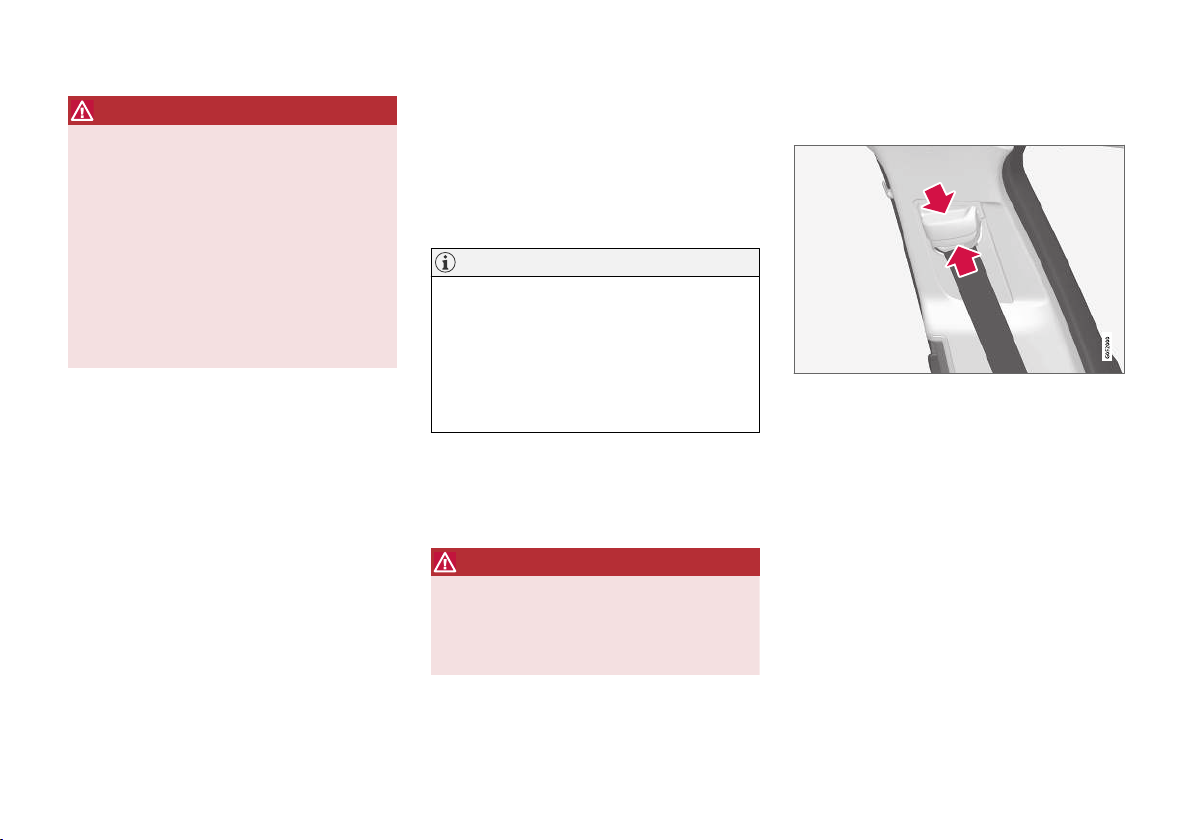
SAFETY
WARNING
Never modify or repair the seatbelts yourself.
Volvo recommends that an authorised Volvo
workshop should be contacted.
If the seatbelt has been subjected to a major
load, such as in conjunction with a collision,
the entire seatbelt must be replaced. Some of
the seatbelt's protective properties may have
been lost even if the seatbelt does not appear
damaged. The seatbelt must also be replaced
if it shows signs of wear or damage. The new
seatbelt must be type-approved and designed
for installation at the same location as the
replaced seatbelt.
Related information
Safety (p. 42)
•
Seatbelt tensioner (p. 46)
•
Putting on and taking off seatbelts (p. 45)
•
Door and seatbelt reminder (p. 48)
•
Putting on and taking off seatbelts
Make sure that all passengers have fastened
their seatbelts before starting to drive.
Putting on seatbelts
1. Pull out the seatbelt slowly and make sure it
is not twisted or damaged.
NOTE
The seatbelt is equipped with an inertia reel
that is locked in the following situations:
if the belt is extended too quickly.
•
during braking and acceleration.
•
if the car leans heavily.
•
when driving in bends.
•
2. Lock the belt by inserting the locking tab in
the intended buckle.
> A loud "click" indicates that the belt has
locked.
WARNING
Always insert the tongue of the seatbelt into
the buckle on the correct side. The seatbelts
and buckles would otherwise possibly not
function as intended in the event of a collision. There is a risk of serous injury.
3. In the front seats the seatbelt can be
adjusted for height.
Press together the seat mounting and move
the seatbelt up or down.
Position the belt as high as possible without
it chafing against your throat.
}}
45
Page 48
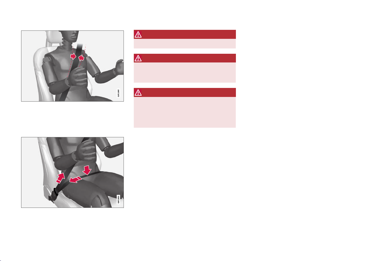
SAFETY
||
The seatbelt must pass over the shoulder (not down over
the arm).
4. Tension the hip strap over the lap by pulling
the diagonal shoulder belt up towards the
shoulder.
The hip strap must be positioned low down (not over the
abdomen).
WARNING
Each seatbelt is designed for only one person.
WARNING
Remember not to clip or hook the seatbelt to
hooks or other interior fittings, as this prevents the belt from tightening properly.
WARNING
Do not make any damages on seatbelts nor
insert any foreign objects into a buckle. The
seatbelts and buckles would then possibly not
function as intended in the event of a collision. There is a risk of serous injury.
Taking off seatbelts
1. Press the red button on the seatbelt buckle
and then let the belt retract.
2. If the seatbelt does not retract fully, feed it in
by hand so that it does not hang loose.
Related information
Seatbelts (p. 44)
•
Seatbelt tensioner (p. 46)
•
Door and seatbelt reminder (p. 48)
•
Seatbelt tensioner
The car is fitted with standard seatbelt tensioners and electric* seatbelt tensioners that can
tension the seatbelts in critical situations and
collisions.
Standard seatbelt tensioner
All the seatbelts are equipped with a standard
seatbelt tensioner.
The seatbelt tensioner tensions the seatbelt in
the event of a collision with sufficient force in
order to more effectively restrain the occupant.
Electric seatbelt tensioner*
The driver and front passenger seatbelts are
equipped with an electric seatbelt tensioner.
The seatbelt tensioners work together and can
be activated together with the driver support systems City Safety and Rear Collision Warning. In
critical situations, such as panic braking, driving
off the road (e.g. the car rolls into a ditch, lifts off
the ground or hits something in the terrain), skidding, or risk of collision, the seatbelt can be tensioned by the seatbelt tensioner's electric motor.
The electric seatbelt tensioner helps to adjust the
occupant to a better position, reducing the risk of
striking the car's interior and improving the effect
of safety systems, such as the car's airbags.
When the critical situation has come to an end,
the seatbelt and the electric seatbelt preten-
46
* Option/accessory.
Page 49
SAFETY
sioner are restored automatically, but they can
also be restored manually.
IMPORTANT
If the passenger airbag is deactivated, the
electric seatbelt tensioner on the passenger
side will also be deactivated.
WARNING
Never modify or repair the seatbelts yourself.
Volvo recommends that an authorised Volvo
workshop should be contacted.
If the seatbelt has been subjected to a major
load, such as in conjunction with a collision,
the entire seatbelt must be replaced. Some of
the seatbelt's protective properties may have
been lost even if the seatbelt does not appear
damaged. The seatbelt must also be replaced
if it shows signs of wear or damage. The new
seatbelt must be type-approved and designed
for installation at the same location as the
replaced seatbelt.
Related information
Seatbelts (p. 44)
•
Putting on and taking off seatbelts (p. 45)
•
Resetting the electric seatbelt tensioner*
•
(p. 47)
Activating and deactivating passenger air-
•
bag* (p. 52)
City Safety™ (p. 334)
•
Rear Collision Warning (p. 349)
•
Resetting the electric seatbelt
tensioner*
The electric seatbelt tensioner is designed to be
reset automatically, but the seatbelt tensioner
can be reset manually if the belt remains
extended.
1. Stop the car at a safe place.
2. Unfasten the seatbelt and then refasten it.
> The seatbelt and electric seatbelt ten-
sioner are reset.
WARNING
Never modify or repair the seatbelts yourself.
Volvo recommends that an authorised Volvo
workshop should be contacted.
If the seatbelt has been subjected to a major
load, such as in conjunction with a collision,
the entire seatbelt must be replaced. Some of
the seatbelt's protective properties may have
been lost even if the seatbelt does not appear
damaged. The seatbelt must also be replaced
if it shows signs of wear or damage. The new
seatbelt must be type-approved and designed
for installation at the same location as the
replaced seatbelt.
Related information
Seatbelt tensioner (p. 46)
•
Seatbelts (p. 44)
•
* Option/accessory.
47
Page 50
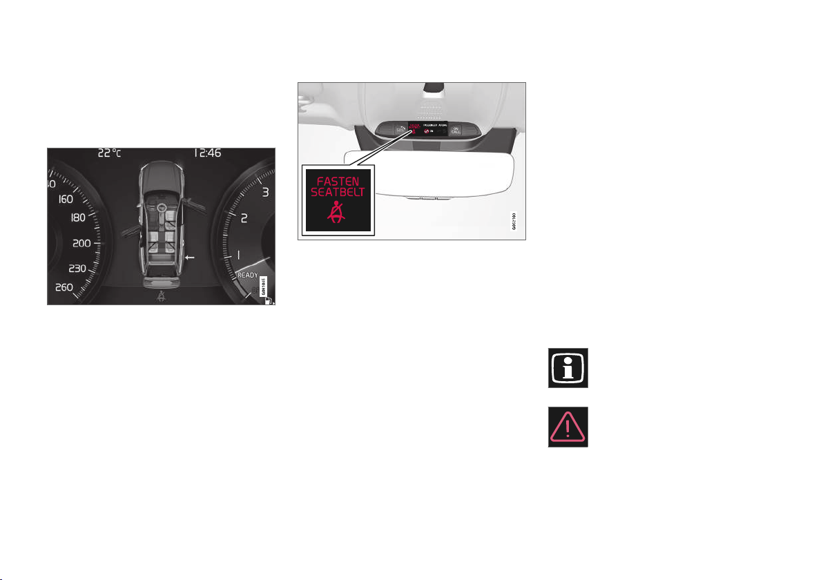
SAFETY
Door and seatbelt reminder
The system reminds unbelted occupants to wear
a seatbelt, and also warns about an open door,
bonnet or lid.
Driver display graphics
Graphics in the driver display with different types of
warnings. The warning colour on the door and tailgate is
dependent on the vehicle's speed.
The driver display's graphics show which seats in
the car are occupied by belted and unbelted passengers.
The same graphic also shows if the bonnet, tailgate, fuel filler flap or any door is open.
The graphic can be acknowledged by pressing
the O button on the right-hand steering wheel
keypad.
Seatbelt reminder
Visual reminder in the roof console.
A visual reminder is given in the roof console and
by means of the warning symbol in the driver display.
The acoustic reminder is dependent on speed,
driving time and distance.
The belt status of the driver and passengers is
shown in the driver display graphics when a belt
is buckled or unbuckled.
Child seats are not covered by the seatbelt
reminder system.
Front seat
A visual and acoustic reminder remind the driver
and front seat passenger to use a seatbelt if
either of them is not wearing one.
Rear seat
The seatbelt reminder in the rear seat has two
subfunctions:
Provides information on which seatbelts are
•
being used in the rear seat. The driver display's graphics are shown when the seatbelts
are in use.
Reminding that a seatbelt in the rear seat is
•
unfastened during a journey by means of a
visual and acoustic reminder. The reminder
will cease once the seatbelt has been put on
again.
Reminder for doors, bonnet, tailgate and fuel filler flap
If the bonnet, tailgate, fuel filler flap or a door is
not closed properly, the driver display's graphics
show what is open. Stop the car in a safe place
as soon as possible and close the source of the
warning.
If the car is driven at a speed lower
than approx. 10 km/h (6 mph) then the
driver display's information symbol illuminates.
If the car is driven at a speed higher
than approx. 10 km/h (6 mph) then the
driver display's warning symbol illuminates.
48
Page 51
SAFETY
Related information
Seatbelts (p. 44)
•
Putting on and taking off seatbelts (p. 45)
•
Airbags
The car is equipped with airbags and inflatable
curtains for driver and passengers.
NOTE
The detectors react differently depending on
the nature of the collision and whether or not
the seatbelts are fastened. Applies to all belt
positions.
It is therefore possible that only one (or none)
of the airbags may inflate in a collision. The
detectors sense the force of the collision on
the vehicle and the action is adapted accordingly so that none, one or more airbags are
deployed.
WARNING
The airbag system's control module is located
in the centre console. If the centre console is
drenched with water or other liquid, disconnect the cables to the starter battery. Do not
attempt to start the car since the airbags may
deploy. Recovering the car. Volvo recommends that it is transported to an authorised
Volvo workshop.
Deployed airbags
If any of the airbags have deployed, the following
is recommended:
Recovering the car. Volvo recommends that it
•
is transported to an authorised Volvo workshop. Do not drive with deployed airbags.
Volvo recommends engaging an authorised
•
Volvo workshop to handle the replacement of
components in the car's safety systems.
Always contact a doctor.
•
WARNING
Never drive with deployed airbags. They can
make steering difficult. Other safety systems
may also be damaged. The smoke and dust
created when the airbags are deployed can
cause skin and eye irritation/injury after intensive exposure. In case of irritation, wash with
cold water. The rapid deployment sequence
and airbag fabric may cause friction and skin
burns.
Related information
Safety (p. 42)
•
Driver airbags (p. 50)
•
Passenger airbag (p. 51)
•
Side airbags (p. 54)
•
Inflatable curtains (p. 55)
•
49
Page 52
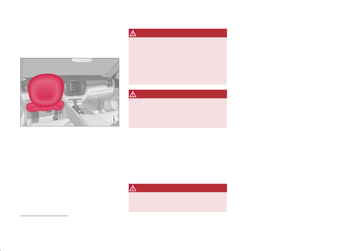
SAFETY
Driver airbags
As a supplement to the seatbelts, the car is
equipped with steering wheel airbag and knee
airbag1 on the driver's side.
Steering wheel airbag and knee airbag1 on the driver's
side in the front seat.
In the event of a frontal collision, the airbags help
to protect the head, neck, face and chest of the
driver as well as the knees and legs.
A sufficiently violent collision trips the sensors
and the airbag/airbags is inflated. The airbag
cushions the initial collision impact for the occupant. The airbag deflates when compressed by
the collision. When this occurs, smoke escapes
into the car. This is completely normal. The entire
process, including inflation and deflation of the
airbag, occurs within tenths of a second.
WARNING
The seatbelts and airbags interact. If the belt
is not used or is used incorrectly, this may
diminish the protection provided by the airbag
in the event of a collision.
To minimise the risk of injury if the airbag
deploys, passengers must sit as upright as
possible with their feet on the floor and backs
against the backrest.
WARNING
Volvo recommends that an authorised Volvo
workshop should be contacted for repair.
Defective work in the airbag system could
cause malfunction and result in serious personal injury.
Steering wheel airbag location
This airbag is fitted into the centre of the steering
wheel. The steering wheel is marked AIRBAG.
Knee airbag1 location
The airbag is folded up in the lower part of the
instrument panel on the driver's side. Its cover
panel is marked AIRBAG.
WARNING
Do not place or attach any object on the top
or front of the panel where the knee airbag is
stowed.
Related information
Airbags (p. 49)
•
Passenger airbag (p. 51)
•
1
The car is only equipped with knee airbag in certain markets.
50
Page 53
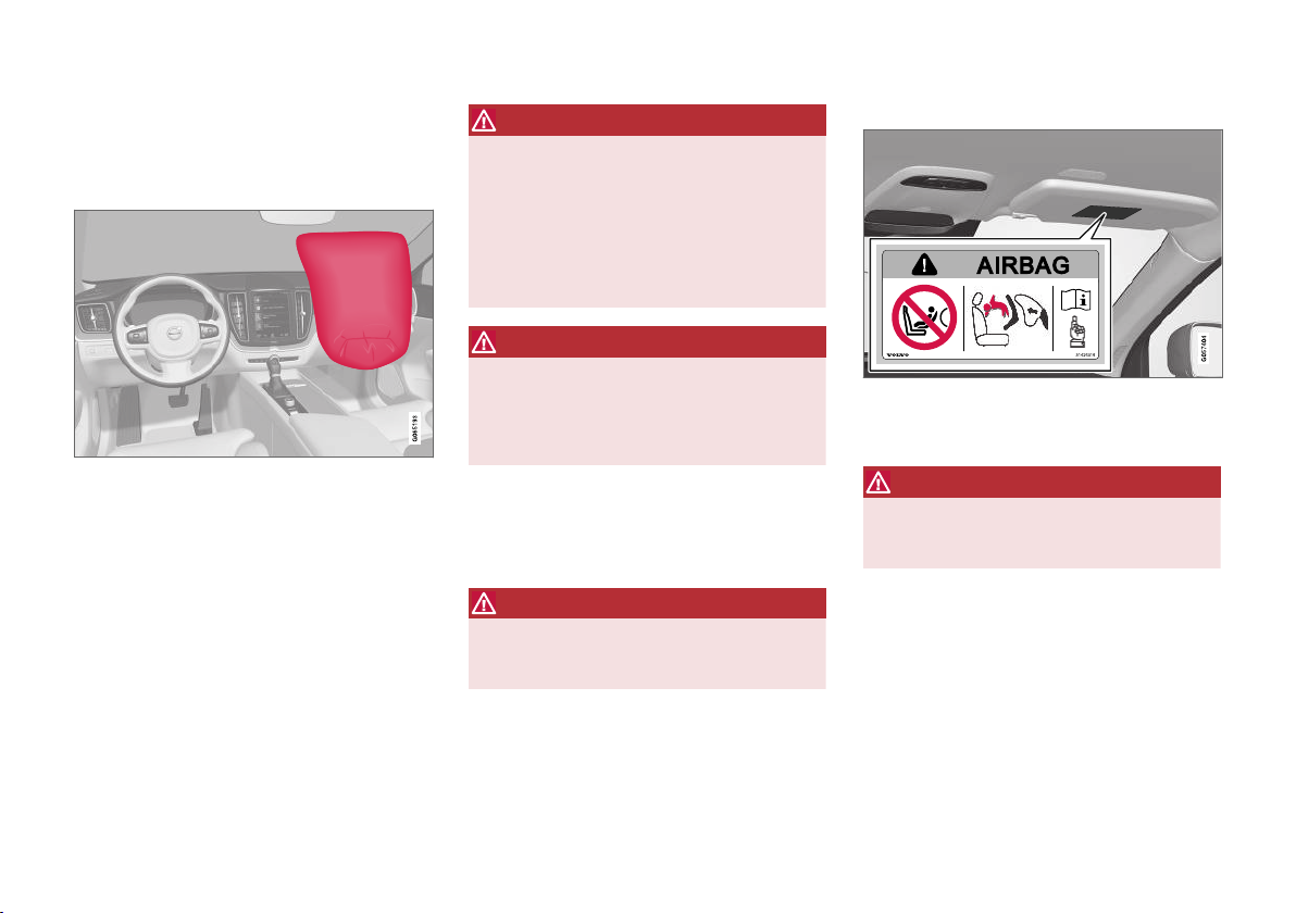
SAFETY
Passenger airbag
As a supplement to the seatbelts, the vehicle is
equipped with an airbag on the passenger side
in the front seat.
Front passenger airbag in front seat.
In the event of a frontal collision, the airbag helps
to protect the head, neck, face and chest of the
passenger as well as the knees and legs.
A sufficiently violent collision trips the sensors
and the airbag is inflated. The airbag cushions
the initial collision impact for the occupant. The
airbag deflates when compressed by the collision.
When this occurs, smoke escapes into the car.
This is completely normal. The entire process,
including inflation and deflation of the airbag,
occurs within tenths of a second.
WARNING
The seatbelts and airbags interact. If the belt
is not used or is used incorrectly, this may
diminish the protection provided by the airbag
in the event of a collision.
To minimise the risk of injury if the airbag
deploys, passengers must sit as upright as
possible with their feet on the floor and backs
against the backrest.
WARNING
Volvo recommends that an authorised Volvo
workshop should be contacted for repair.
Defective work in the airbag system could
cause malfunction and result in serious personal injury.
Passenger airbag location
The airbag is folded up into a compartment
above the glovebox. Its cover panel is marked
AIRBAG.
WARNING
Do not put objects in front of or above the
dashboard where the passenger airbag is
located.
Label for passenger airbag
Label on the passenger side's sun visor.
The warning label for the passenger airbag is
positioned as shown above.
WARNING
If the car is not equipped with a switch to activate/deactivate the passenger airbag, the airbag will always be activated.
}}
51
Page 54
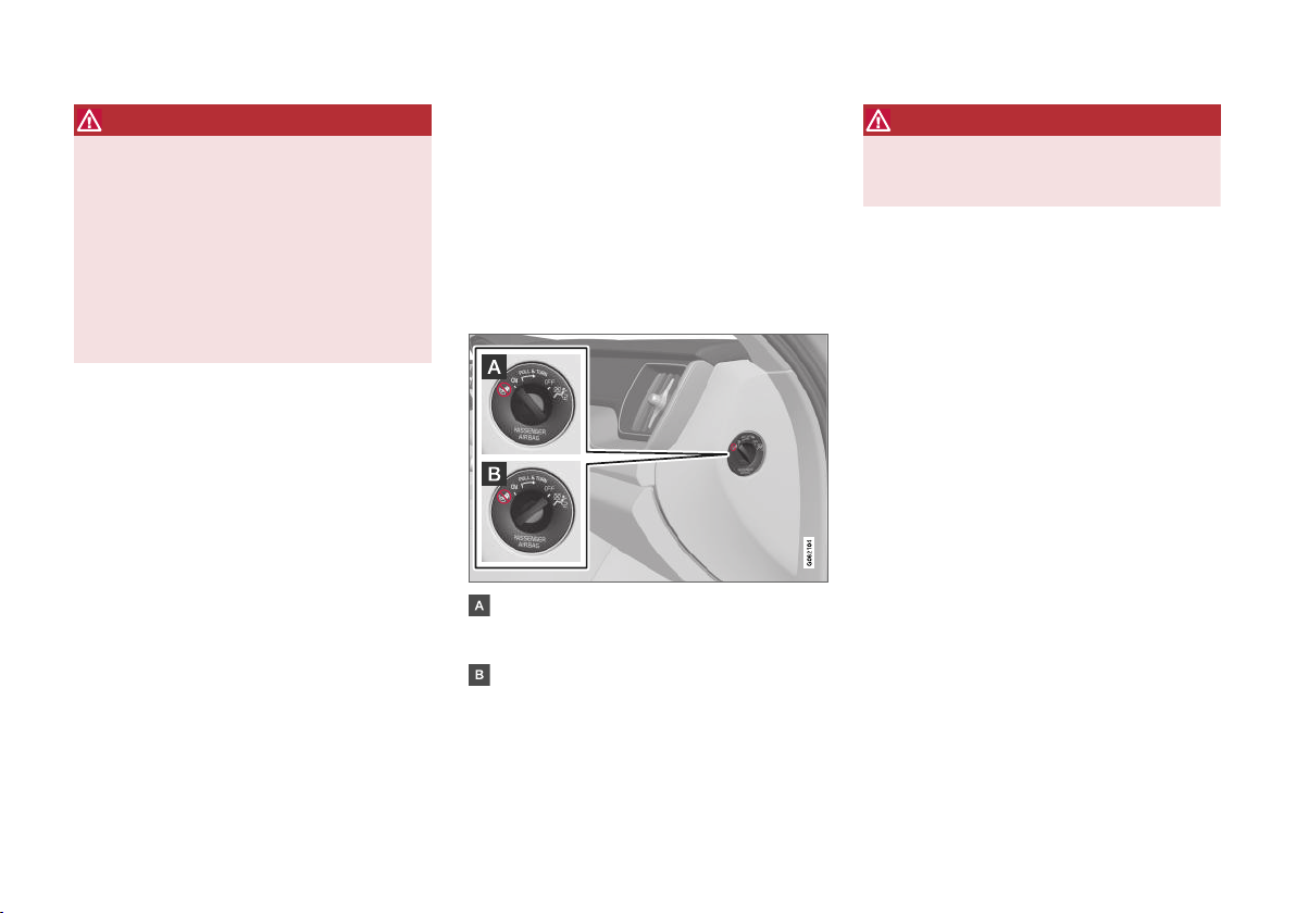
SAFETY
||
WARNING
Never allow anybody to stand or sit in front of
the front passenger seat.
Never use a rear-facing child seat on the front
passenger seat if the airbag is activated.
Front-facing passengers (children and adults)
must never sit on the front passenger seat if
the passenger airbag is deactivated.
Failure to follow the advice given above can
endanger life or lead to serious personal
injury.
Related information
Airbags (p. 49)
•
Driver airbags (p. 50)
•
Activating and deactivating passenger air-
•
bag* (p. 52)
Activating and deactivating passenger airbag*
The passenger airbag can be deactivated if the
car is equipped with a switch, Passenger Airbag
Cut Off Switch (PACOS).
The switch for the passenger airbag is located on
the passenger end of the instrument panel and is
accessible when the passenger door is open.
Check that the switch is in the required position.
ON - the airbag is activated and all front-facing passengers (children and adults) can sit
safely on the passenger seat.
OFF - The airbag is deactivated and children
in rear-facing child seats can sit safely on the
passenger seat.
WARNING
If the car is not equipped with a switch to activate/deactivate the passenger airbag, the airbag will always be activated.
52
* Option/accessory.
Page 55
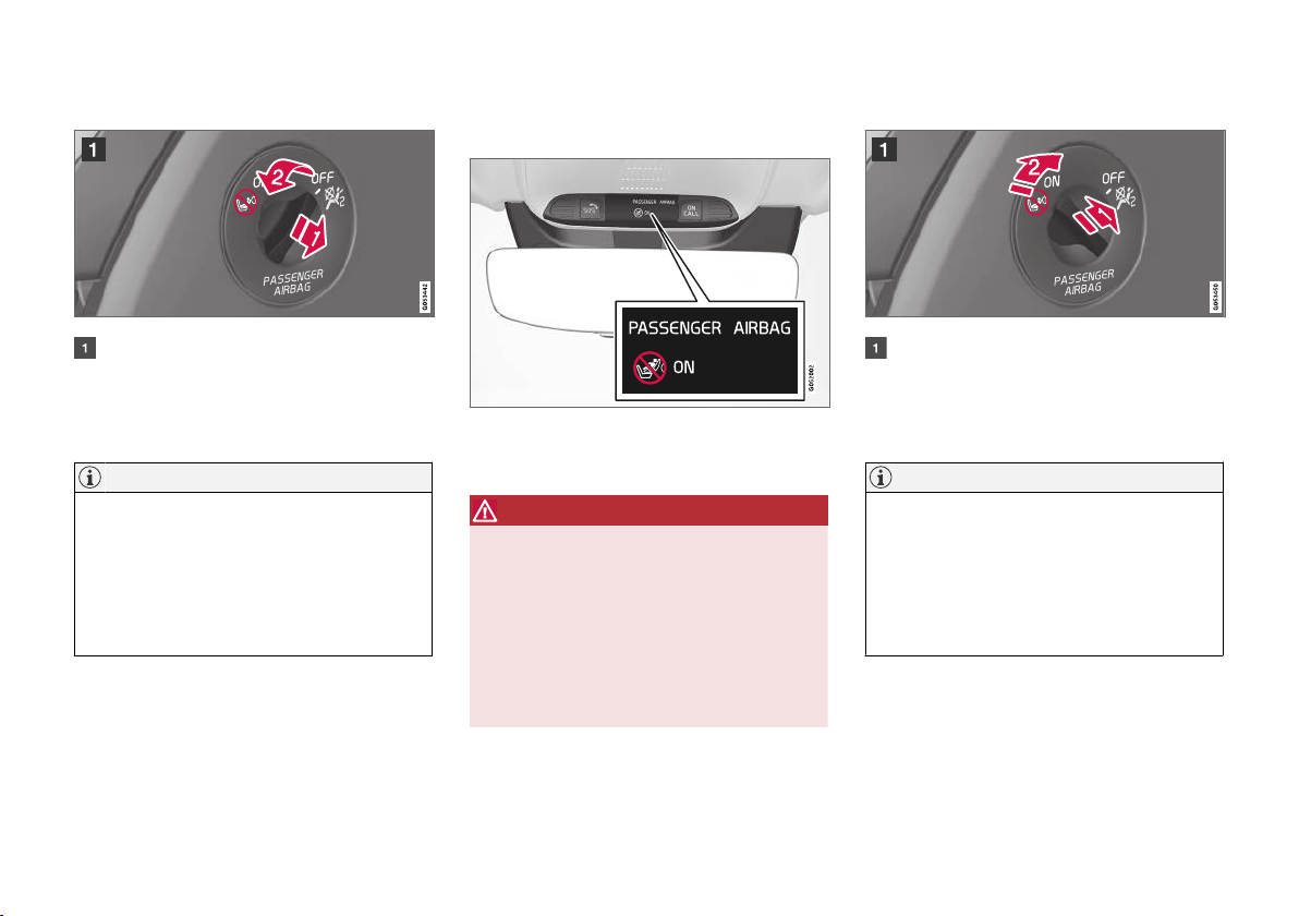
SAFETY
Activating passenger airbag
Pull the switch outward and turn from OFF to
ON.
> The driver display shows the message
Passenger airbag on Please
acknowledge.
NOTE
If the passenger airbag has been activated/
deactivated with the car in ignition position I
or lower, a message is shown in the driver
display and the following indicator in the roof
console approx. 6 seconds after the car's
electrical system has been set in ignition
position II.
2. Confirm the message by pressing the righthand steering wheel keypad's O button.
> A text message and a warning symbol in
the roof console indicate that the airbag
for the front passenger seat is activated.
WARNING
Never use a rear-facing child seat on the front
passenger seat when the airbag is activated.
The passenger airbag must always be activated when front-facing passengers (children
and adults) are sitting in the front passenger
seat.
Failure to follow the advice given above can
endanger life or lead to serious personal
injury.
Deactivating passenger airbag
Pull the switch outward and turn from ON to
OFF.
> The driver display shows the message
Passenger airbag off Please
acknowledge.
NOTE
If the passenger airbag has been activated/
deactivated with the car in ignition position I
or lower, a message is shown in the driver
display and the following indicator in the roof
console approx. 6 seconds after the car's
electrical system has been set in ignition
position II.
}}
53
Page 56
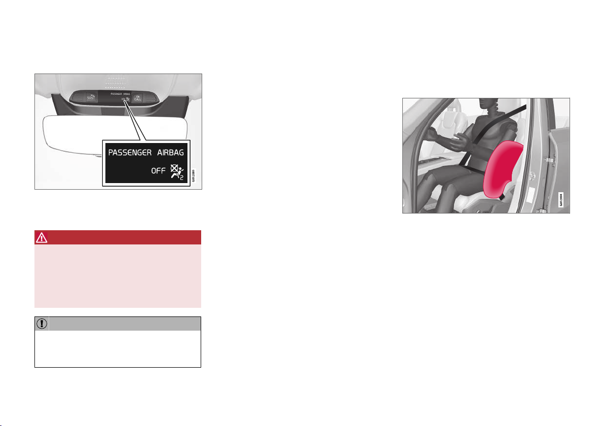
SAFETY
2. Confirm the message by pressing the right-
||
hand steering wheel keypad's O button.
> A text message and a symbol in the roof
console indicate that the airbag for the
front passenger seat is deactivated.
WARNING
Front-facing passengers (children and adults)
must never sit on the passenger seat when
the airbag is deactivated.
Failure to follow the advice given above can
endanger life or lead to serious personal
injury.
IMPORTANT
If the passenger airbag is deactivated, the
electric seatbelt tensioner on the passenger
side will also be deactivated.
Related information
Seatbelt tensioner (p. 46)
•
Child seats (p. 58)
•
Side airbags
The side airbags on the driver's and passenger
seats act to protect the chest and hips in the
event of a collision.
The side airbags are fitted in the outer backrest
frames of the front seats and help to protect the
driver and passengers in the front seat.
A sufficiently violent collision trips the sensors
and the side airbags are inflated. The airbag
inflates between the occupant and the door
panel and thereby cushions the initial impact. The
airbag deflates when compressed by the collision.
The side airbag is normally only deployed on the
side of the collision.
54
Page 57
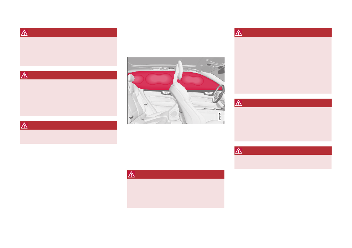
SAFETY
WARNING
Volvo recommends that an authorised Volvo
workshop should be contacted for repair.
Defective work in the side airbag system
could cause malfunction and result in serious
personal injury.
WARNING
Do not put objects in the area between the
outside of the seat and the door panel, since
this area is required by the side airbag.
Volvo recommends the use only of car seat
covers approved by Volvo. Other seat covers
may impede the operation of the side airbags.
WARNING
Side airbags are a supplement the seatbelts.
Always use a seatbelt.
Side airbags and child seats
The protection provided by the car to children
seated in a child seat or on a booster cushion is
not diminished by the side airbag.
Related information
Airbags (p. 49)
•
Inflatable curtains
The Inflatable Curtain (IC), helps to prevent the
driver and passengers from striking their heads
on the inside of the car during a collision.
The inflatable curtain is mounted along both
sides of the headlining and helps protect the
driver and outer seat passengers of the car. The
panels are labelled with IC AIRBAG.
A sufficiently violent collision trips the sensors
and the inflatable curtain is inflated.
WARNING
Volvo recommends that an authorised Volvo
workshop should be contacted for repair.
Defective work in the inflatable curtain system
can cause malfunction and result in serious
personal injury.
WARNING
Never hang or attach heavy items onto the
handles in the roof. The hooks are only
designed for light coats and jackets (not for
solid objects such as umbrellas).
Do not screw or install anything onto the car's
headlining, door pillars or side panels. This
could compromise the intended protection.
Volvo recommends only using Volvo genuine
parts that are approved for fitting within these
areas.
WARNING
Leave 10 cm (4 inches) space between the
load and the side windows if the car is loaded
to above the top edge of the door windows.
Otherwise, the intended protection of the
inflatable curtain, which is concealed in the
headlining, may be compromised.
WARNING
The inflatable curtain is a supplement to the
seatbelts. Always use a seatbelt.
Related information
Airbags (p. 49)
•
55
Page 58
SAFETY
Safety mode
Safety mode is a protective state that is triggered when a collision may have damaged any
of the car's vital functions, such as the fuel lines,
sensors for any of the safety systems, or the
brake system.
If the car has been in a collision, the message
Safety mode See Owner's manual may be
shown on the driver display with a warning symbol as long as the display is not damaged and the
car's electrical system is still in working order.
This message means that the car has reduced
functionality.
WARNING
Never, under any circumstances, attempt to
restart the car if it smells of fuel when the
Safety mode See Owner's manual mes-
sage is shown in the driver display. Leave the
car at once.
If the car is in safety mode, it is possible to
attempt to reset the system in order to start and
move the car for a short distance, if in a dangerous traffic situation for example.
WARNING
Never attempt to repair your car or reset the
electronics yourself if the car has been in
safety mode. This could result in personal
injury or the car not functioning as normal.
Volvo recommends that engaging an authorised Volvo workshop to check and restore the
car to normal status after
Owner's manual has been shown.
Safety mode See
WARNING
If the car is in safety mode it must not be
towed. It must be transported from its location. Volvo recommends that it is transported
to an authorised Volvo workshop.
Related information
Safety (p. 42)
•
Starting and moving the car after safety
•
mode (p. 56)
Recovery (p. 490)
•
Starting and moving the car after safety mode
If the car is in safety mode, it is possible to
attempt to reset the system in order to start and
move the car for a short distance, if in a dangerous traffic situation for example.
Starting the car after safety mode
1. Check the general damage situation of the
car and whether any fuel has been leaking.
There must be no smell of fuel either.
If there is only minor damage and a check
has revealed no fuel leaks, starting can be
attempted.
WARNING
Never, under any circumstances, attempt to
restart the car if it smells of fuel when the
Safety mode See Owner's manual mes-
sage is shown in the driver display. Leave the
car at once.
2. Switch off the car.
3. Then try to start the car.
> The car's electronics carry out a systems
check and then try to resume normal status. The driver display shows the message
Car start System check, wait during
this time. This can take up to one minute.
56
Page 59
SAFETY
4. Then try to start the car again when the mes-
Car start System check, wait is no
sage
longer shown in the driver's display.
IMPORTANT
If the message Safety mode See Owner's
manual is still shown on the display the car
must not be driven or towed but a vehicle
recovery service must then be used instead.
Even if the car appears to be driveable, hidden damage may make the car impossible to
control once moving.
Moving the car after safety mode
1. If the driver display shows the message
Normal mode The car is now in normal
mode after a start attempt, the car can be
carefully moved if standing in a dangerous
position.
2. Do not move the car further than necessary.
WARNING
If the car is in safety mode it must not be
towed. It must be transported from its location. Volvo recommends that it is transported
to an authorised Volvo workshop.
Related information
Safety mode (p. 56)
•
Starting the car (p. 432)
•
Recovery (p. 490)
•
Child safety
Children must always sit secure while travelling
in the car.
Volvo has child safety equipment (child seats and
attachment devices) which is designed for fitting
in this particular car. Using Volvo's child safety
equipment, you obtain the optimum conditions for
a child to travel safely in the car. In addition, the
child safety equipment fits in well and is simple to
use.
The equipment that should be used is selected
taking account of the weight and size of the child.
Volvo recommends that children travel in a rearfacing child seat until as late an age as possible,
at least until 3-4 years of age, and then in a
front-facing child seat until the child is 140 cm
(4 feet 7 inches) tall.
NOTE
Legal provisions about the type of child seat
that must be used for children of different
ages and heights vary from country to country. Check what does apply.
}}
57
Page 60
SAFETY
||
NOTE
When using child safety equipment, it is
important to read the installation instructions
included.
In the event of questions when fitting child
safety equipment, contact the manufacturer
for clearer instructions.
Children of all ages and sizes must always sit
correctly secured in the car. Never allow a child to
sit on the knee of a passenger.
Related information
Safety (p. 42)
•
Child seats (p. 58)
•
Activating and deactivating child safety locks
•
(p. 262)
Child seats
Suitable child seats should always be used
when children are travelling in the car.
Children should sit comfortably and safely. Make
sure that the child seat is positioned, mounted
and used correctly.
Look in the installation instructions for the child
seat for the correct fitting.
NOTE
When using child safety equipment, it is
important to read the installation instructions
included.
In the event of questions when fitting child
safety equipment, contact the manufacturer
for clearer instructions.
NOTE
Never leave a child seat loose in the car.
Always secure it according to the instructions
for the child seat, even when it is not in use.
Related information
Child safety (p. 57)
•
Integrated child seat* (p. 70)
•
Upper mounting points for child seats
•
(p. 59)
Lower mounting points for child seats
•
(p. 59)
i-Size/ISOFIX mounting points for child seats
•
(p. 60)
Child seat positioning (p. 61)
•
Activating and deactivating passenger air-
•
bag* (p. 52)
58
* Option/accessory.
Page 61
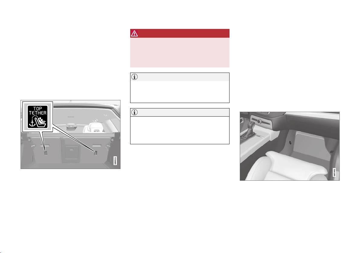
SAFETY
Upper mounting points for child seats
The car is equipped with upper mounting points
for child seats on the rear seat's outer seats.
The upper mounting points are primarily intended
for use with front-facing child seats.
Always follow the manufacturer's installation
instructions when connecting a child seat to the
upper mounting points.
The location of the mounting points
Mounting point locations are indicated by symbols on
the rear of the backrest.
The mounting points are located on the rear of
the rear seat's outer seats.
WARNING
The child seat's upper straps must be routed
through the hole in the head restraint leg
before they are tensioned at the mounting
point. If this is not possible, follow the recommendations from the child seat manufacturer.
NOTE
Fold the head restraints in order to facilitate
fitting this type of child seat in cars with folding head restraints on the outer seats.
NOTE
In cars with a cargo cover over the luggage
compartment, this must be removed before
child seats can be attached to the securing
points.
Related information
Child seats (p. 58)
•
Lower mounting points for child seats
•
(p. 59)
i-Size/ISOFIX mounting points for child seats
•
(p. 60)
Table for location of child seats using the
•
car's seatbelts (p. 64)
Lower mounting points for child
seats
The car is equipped with lower mounting points
for child seats in the front seat* and the rear
seat.
The lower mounting points are designed to be
used in conjunction with certain rear-facing child
seats.
Always follow the manufacturer's installation
instructions when connecting a child seat to the
lower mounting points.
The location of the mounting points
Mounting point locations in the front seat.
The mounting points in the front seat are located
on the sides of the passenger seat's legroom.
* Option/accessory.
}}
59
Page 62
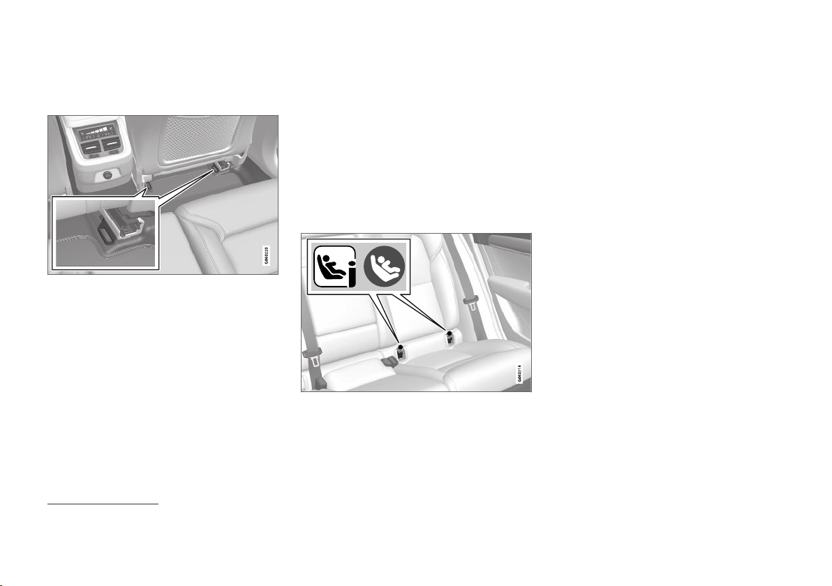
SAFETY
The mounting points in the front seat are only
||
mounted if the vehicle is equipped with a switch
to activate/deactivate the passenger airbag*.
Mounting point locations in the rear seat.
The mounting points in the rear seat are located
on the rear section of the front seat's floor rails.
Related information
Child seats (p. 58)
•
Upper mounting points for child seats (p. 59)
•
i-Size/ISOFIX mounting points for child seats
•
(p. 60)
Table for location of child seats using the
•
car's seatbelts (p. 64)
i-Size/ISOFIX mounting points for
child seats
The car is equipped with i-Size/ISOFIX mounting points for child seats in the rear seat.
i-Size/ISOFIX2 is a fixture system for car child
seats that is based on an international standard.
Always follow the manufacturer's installation
instructions when connecting a child seat to the
i-Size/ISOFIX mounting points.
The location of the mounting points
Mounting point locations are indicated by symbols2 on
the upholstery of the backrest.
The mounting points for i-Size/ISOFIX are
located behind covers in the lower section of the
rear seat's backrest, in the outer seats.
Lift the covers in order to access the mounting
points.
Related information
Child seats (p. 58)
•
Upper mounting points for child seats (p. 59)
•
Lower mounting points for child seats (p. 59)
•
Table for location of i-Size child seats
•
(p. 66)
Table for location of ISOFIX child seats
•
(p. 67)
2
Names and symbols change depending on market.
60
* Option/accessory.
Page 63
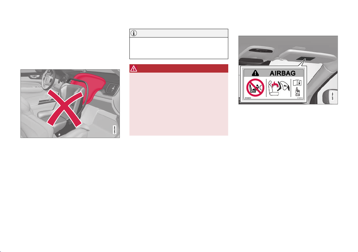
SAFETY
Child seat positioning
It is important to position the child seat in the
right place in the car. The choice of location
depends, amongst other things, on the type of
child seat and whether the passenger airbag is
activated.
Rear-facing child seat and airbag are not compatible.
Always fit rear-facing child seats in the rear seat
if the passenger airbag is activated. If a child is
sitting on the front passenger seat then he/she
could suffer serious injury if the airbag deploys.
If the passenger airbag is deactivated then rearfacing child seats can be fitted on the front passenger seat.
NOTE
Regulations regarding the placement of children in cars vary from country to country.
Check what does apply.
WARNING
Never allow anybody to stand or sit in front of
the front passenger seat.
Never use a rear-facing child seat on the front
passenger seat if the airbag is activated.
Front-facing passengers (children and adults)
must never sit on the front passenger seat if
the passenger airbag is deactivated.
Failure to follow the advice given above can
endanger life or lead to serious personal
injury.
Label for passenger airbag
Label on the passenger side's sun visor.
The warning label for the passenger airbag is
positioned as shown above.
Related information
Child seats (p. 58)
•
Child seat mounting (p. 62)
•
Table for location of child seats using the
•
car's seatbelts (p. 64)
Table for location of i-Size child seats
•
(p. 66)
Table for location of ISOFIX child seats
•
(p. 67)
61
Page 64
SAFETY
Child seat mounting
It is important to remember a number of things
when a child seat is mounted and used, which
depend on where the child seat is positioned.
WARNING
Booster cushions/child seats with steel
braces or some other design that could rest
on the seatbelt buckle's opening button must
not be used, as they could cause the seatbelt
buckle to open accidentally.
Do not secure the straps for the child seat
into the seat's horizontal adjustment bar or in
springs, rails or beams under the seat. Sharp
edges may damage the straps.
Do not allow the upper section of the child
seat to rest against the windscreen.
NOTE
When using child safety equipment, it is
important to read the installation instructions
included.
In the event of questions when fitting child
safety equipment, contact the manufacturer
for clearer instructions.
NOTE
Never leave a child seat loose in the car.
Always secure it according to the instructions
for the child seat, even when it is not in use.
Installation in the front seat
When fitting rear-facing child seats, check
•
that the passenger airbag is deactivated.
When fitting front-facing child seats, check
•
that the passenger airbag is activated.
Only use child seats that are recommended
•
by Volvo, are universally approved or are
semi-universal, and where the car is included
on the manufacturer's vehicle list.
ISOFIX child seats can only be fitted when
•
the car is equipped with the ISOFIX console
accessory.
If the child seat is equipped with lower
•
straps, Volvo recommends that the lower
mounting points are used with these3.
If the child seat is equipped with support
•
legs, always fit the support leg/support legs
directly to the floor. Never fit a support leg to
a footrest or other object.
The ISOFIX guide can be used in order to
•
facilitate child seat installation.
Installation in the rear seat
Only use child seats that are recommended
•
by Volvo, are universally approved or are
semi-universal, and where the car is included
on the manufacturer's vehicle list.
A child seat with support legs must not be
•
fitted in the centre seat.
The outer seats are equipped with the
•
ISOFIX fixture system and are approved for
i-Size4.
The outer seats are equipped with upper
•
mounting points. Volvo recommends that
child seat's upper straps should be pulled
through the hole in the head restraint before
being tensioned at the mounting point. If this
3
is not possible, follow the recommendations
from the child seat manufacturer.
If the child seat is equipped with lower
•
straps, never adjust the position of the seat
in front after the straps have been fitted in
the lower mounting points. Always remember
to remove the lower straps when the child
seat is not installed.
If the child seat is equipped with support
•
legs, always fit the support leg/support legs
directly to the floor. Never fit a support leg to
a footrest or other object.
3
The accessory range varies depending on market.
4
Varies depending on market.
62
Page 65

Related information
Child seat positioning (p. 61)
•
Table for location of child seats using the
•
car's seatbelts (p. 64)
Table for location of i-Size child seats
•
(p. 66)
Table for location of ISOFIX child seats
•
(p. 67)
SAFETY
63
Page 66
SAFETY
Table for location of child seats using the car's seatbelts
The table gives a recommendation for which
child seats suit which locations, and for what
size of child.
NOTE
Always read the owner's manual section on
installing a child seat before installing one in
the car.
Weight Front seat (with deactivated airbag, only rear-facing
child seats)
Group 0
max 10 kg
Group 0+
max 13 kg
Group 1
9-18 kg
Group 2
15-25 kg
A
B, C
U
B, C
U
D
L
D
L
Front seat (with activated airbag, only front-facing
child seats)
A
X
X
B, E
UF
B, F
UF
Outer rear seat Centre rear seat
UE, L
UF, B*
C
U
C
U
D
, G
D
, L
C
U
C
U
E
U
F
U
64
* Option/accessory.
Page 67
SAFETY
Weight Front seat (with deactivated airbag, only rear-facing
child seats)
Group 3
22-36 kg
A
X
Front seat (with activated airbag, only front-facing
child seats)
A
B, F
UF
U: Suitable for universal category restraints approved for use in this mass group.
UF: Suitable for front-facing universally approved child seats.
L: Suitable for particular child restraints. These restraints may be of the specific vehicle, restricted or semi-universal categories.
B: Built-in restraint approved for this mass group.
X: The seat is not suitable for children in this mass group.
A
The seat cushion extension must always be retracted for the installation of child seats.
B
Adjust the backrest to a more upright position.
C
Volvo recommends: Volvo infant seat (type approval E1 04301146).
D
Volvo recommends: Volvo rear-facing seat (type approval E5 04212).
E
Volvo recommends rear-facing child seat for children in this mass group.
F
Volvo recommends: Booster cushion with and without back (type approval E5 04216); Volvo booster seat (type approval E1 04301312).
G
Volvo recommends: Integrated child seat (type approval E5 04220).
Table for location of ISOFIX child seats
WARNING
Never use a rear-facing child seat on the front
passenger seat if the passenger airbag is
•
(p. 67)
Seatbelts (p. 44)
•
activated.
Related information
Child seat positioning (p. 61)
•
Child seat mounting (p. 62)
•
Table for location of i-Size child seats
•
(p. 66)
Outer rear seat Centre rear seat
UF, B*
, G
F
U
* Option/accessory.
65
Page 68
SAFETY
Table for location of i-Size child seats
The table gives a recommendation for which
i-Size child seats suit which locations, and for
what size of child.
Type of child seat Front seat (with deactivated airbag, only rear-
facing child seats)
i-Size child seats X X
i-U: Suitable for i-Size "universal" child seat, front-facing and rear-facing.
X: Not suitable for universally approved child seats.
A
Volvo recommends rear-facing child seats for this group.
B
Volvo recommends: BeSafe iZi Kid X2 i-Size (type approval E4-129R-000002).
The child seat must be approved in accordance
with UN Reg R129.
Front seat (with activated airbag, only front-fac-
ing child seats)
Related information
Child seat positioning (p. 61)
•
Child seat mounting (p. 62)
•
Table for location of child seats using the
•
car's seatbelts (p. 64)
Table for location of ISOFIX child seats
•
(p. 67)
i-Size/ISOFIX mounting points for child seats
•
(p. 60)
NOTE
Always read the owner's manual section on
installing a child seat before installing one in
the car.
Outer rear seat Centre rear seat
i-U
A, B
X
66
Page 69
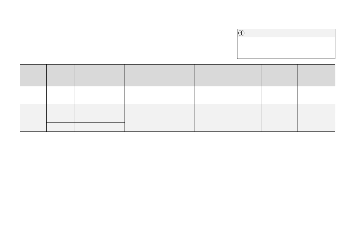
SAFETY
Table for location of ISOFIX child seats
The table gives a recommendation for which
ISOFIX child seats suit which locations, and for
what size of child.
Weight
Group 0
max 10 kg
Group 0+
max 13 kg
Size class
A
Type of child seat Front seat (with deactivated air-
E Rear-facing infant seat
E Rear-facing infant seat
D Rear-facing child seat
The child seat must be approved in accordance
with UN Reg R44 and the car model must be
included in the manufacturer's vehicle list.
Front seat (with activated air-
bag, only rear-facing child
B, C
seats)
B, D
E
IL
, X
B, D, F
E
IL
, X
bag, only front-facing child
seats)
NOTE
Always read the owner's manual section on
installing a child seat before installing one in
the car.
Outer rear seat Centre rear seat
B, C
X
X
D
IL
D
IL
X
XC Rear-facing child seat
}}
67
Page 70
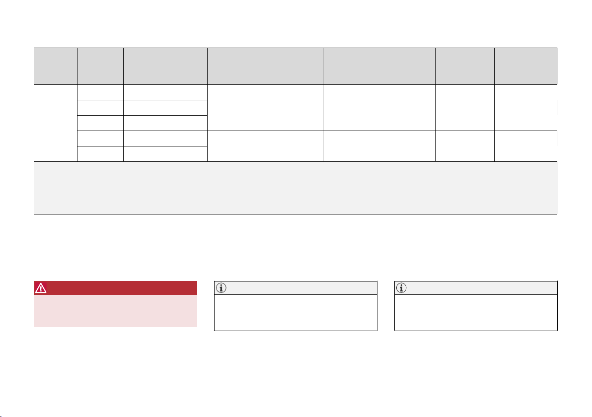
SAFETY
||
Weight
Size class
A
Type of child seat Front seat (with deactivated air-
bag, only rear-facing child
B, C
seats)
Front seat (with activated air-
bag, only front-facing child
B, C
seats)
Outer rear seat Centre rear seat
A Front-facing child seat
B, F, G
Group 1
9-18 kg
B1 Front-facing child seat
C Rear-facing child seat
D Rear-facing child seat
X
B, F
E
IL
, X
IL
E
, X
X IL X
ILG, IUF
G
IL: Suitable for particular ISOFIX child restraint systems. These child restraint systems are those of the specific vehicle, restricted or semi-universal categories.
IUF: Suitable for ISOFIX forward child restraint systems of universal category approved for use in the mass group.
X: Not suitable for ISOFIX child restraint systems.
A
For child seats with the ISOFIX fixture system there is a size classification to help users choose the right type of child seat. The size class can be read on the child seat's label.
B
Works for the installation of ISOFIX child seats that are semi-universally approved (IL) if the car is equipped with the ISOFIX console accessory (the accessory range varies depending on market). There are no
upper mounting points for child seats here.
C
The seat cushion extension must always be retracted for the installation of child seats.
D
Volvo recommends: Volvo infant seat secured using the ISOFIX fixture system (type approval E1 04301146).
E
Applicable if the car is not fitted with an ISOFIX bracket.
F
Adjust the backrest so that the head restraint does not interfere with the child seat.
G
Volvo recommends rear-facing child seat for children in this mass group.
WARNING
Never use a rear-facing child seat on the front
passenger seat if the passenger airbag is
activated.
NOTE
If an i-Size/ISOFIX child seat has no size
classification, the car model must be included
on the vehicle list for the child seat.
NOTE
Volvo recommends contacting an authorised
Volvo dealer for information about which
i-Size/ISOFIX child seats Volvo recommends.
XB Front-facing child seat
68
Page 71

Related information
Child seat positioning (p. 61)
•
Child seat mounting (p. 62)
•
Table for location of child seats using the
•
car's seatbelts (p. 64)
Table for location of i-Size child seats (p. 66)
•
i-Size/ISOFIX mounting points for child seats
•
(p. 60)
SAFETY
69
Page 72
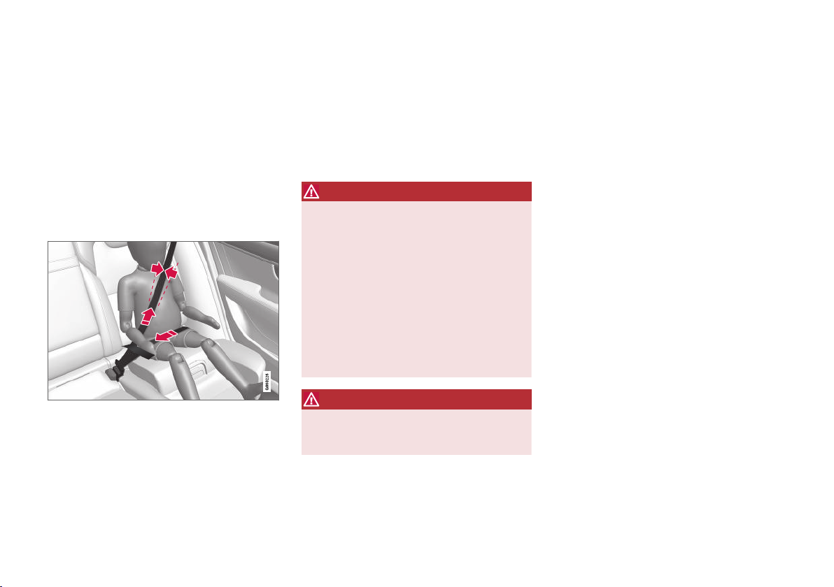
SAFETY
Integrated child seat*
The integrated child seats on the outer positions
in the rear seat allow children to sit comfortably
and safely.
The child seat is specially designed to provide
children with good safety, together with the car's
seatbelt. The seat cushion can be raised in two
positions depending on the weight of the child.
The child seat is approved for children who weigh
15-36 kg (33-80 lbs) and are at least 95 cm (37
inches) tall.
Correct position, the seatbelt should be positioned in on
the shoulder.
Check before driving that:
the seat cushion is raised to the correct posi-
•
tion for the weight of the child
the seat cushion in locked in position
•
the seatbelt is in contact with the child's
•
body and is not slack or twisted
the seatbelt does not lie across the child's
•
throat or below the shoulder
the lap section of the seatbelt is positioned
•
low over the pelvis to provide optimal protection.
WARNING
Volvo recommends that repair or replacement
of the integrated child seat is only performed
by an authorised Volvo workshop. Do not
make any modifications or additions to the
child seat. If an integrated child seat has been
subjected to a heavy load, e.g. in connection
with a collision, then the seat cushion, seatbelt and backrest, or possibly the whole seat,
must be replaced. Even if the child seat
appears to be undamaged, it may not afford
the same level of protection. This also applies
if the seat cushion was in lowered position
during a collision or similar. The seat cushion
must also be replaced if it is heavily worn.
WARNING
If the instructions for the integrated child seat
are not followed then the child could sustain
serious injury in the event of an accident.
Related information
Child seats (p. 58)
•
Folding up the seat cushion in the integrated
•
child seat* (p. 71)
Folding down the seat cushion in the inte-
•
grated child seat* (p. 72)
70
* Option/accessory.
Page 73
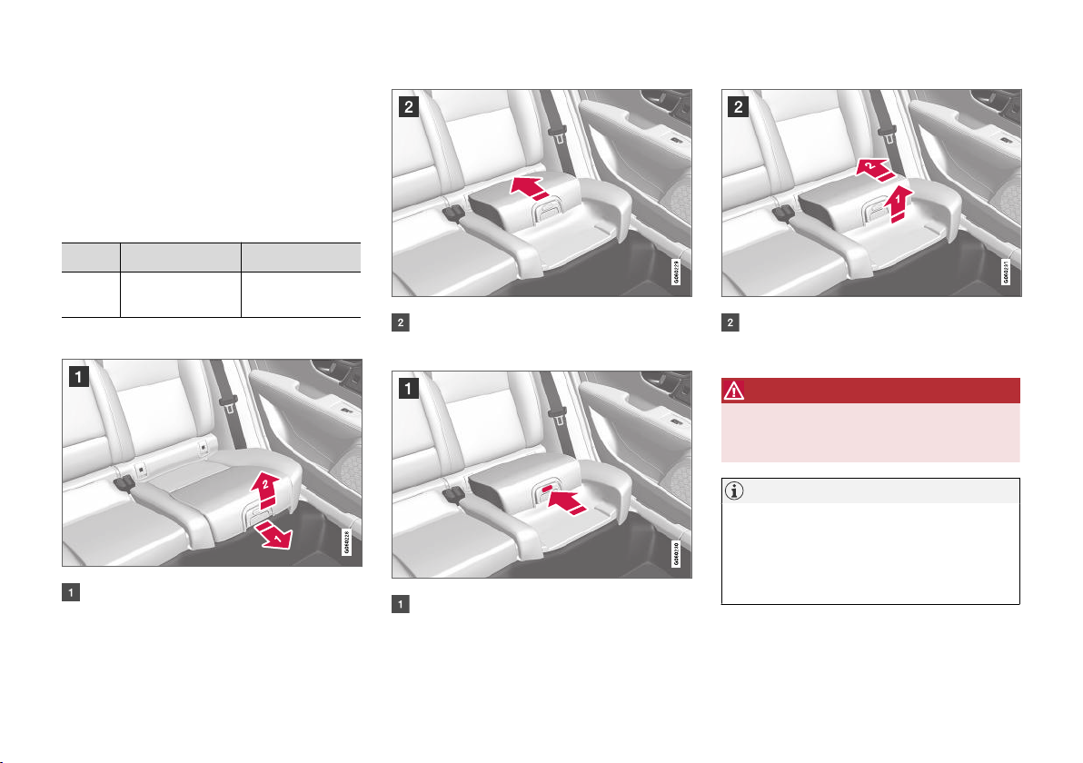
Folding up the seat cushion in the integrated child seat*
The seat cushion should always be folded up
when the integrated child seat is in use.
The seat cushion can be folded up in two positions. The position that should be used depends
on the weight of the child.
Lower position Upper position
Weight 22-36 kg
(50-80 lbs)
Lower position:
Pull the handle forwards and upwards to
release the seat cushion.
15-25 kg
(33-55 lbs)
Press the seat cushion backwards to lock.
Upper position, start from the lower position:
Press the button to release the seat cushion.
SAFETY
Lift the seat cushion up at the front edge
and press it back against the backrest to
lock.
WARNING
If the instructions for the integrated child seat
are not followed then the child could sustain
serious injury in the event of an accident.
NOTE
It is not possible to adjust the seat cushion
from the upper position to the lower position.
From the upper position, the seat cushion
must first be fully lowered into the rear seat,
and then folded up to the lower position.
* Option/accessory.
}}
71
Page 74
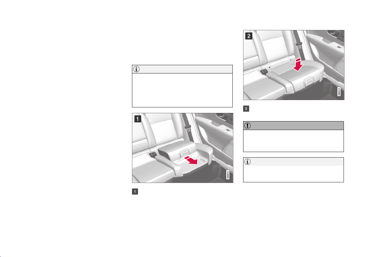
SAFETY
||
Related information
Integrated child seat* (p. 70)
•
Folding down the seat cushion in the inte-
•
grated child seat* (p. 72)
Folding down the seat cushion in the integrated child seat*
The seat cushion should be folded down into
the rear seat when the integrated child seat is
not being used.
NOTE
It is not possible to adjust the seat cushion
from the upper position to the lower position.
From the upper position, the seat cushion
must first be fully lowered into the rear seat,
and then folded up to the lower position.
Press down with your hand in the centre of
the seat cushion in order to lock it.
IMPORTANT
Check that there are no loose objects (e.g.
toys) left behind in the space under the child
seat's seat cushion before lowering.
NOTE
Before the rear backrest is lowered, the child
seat's seat cushion must be lowered first.
72
Pull the handle forwards to release the seat
cushion.
Related information
Integrated child seat* (p. 70)
•
Folding up the seat cushion in the integrated
•
child seat* (p. 71)
* Option/accessory.
Page 75

DISPLAYS AND VOICE CONTROL
Page 76
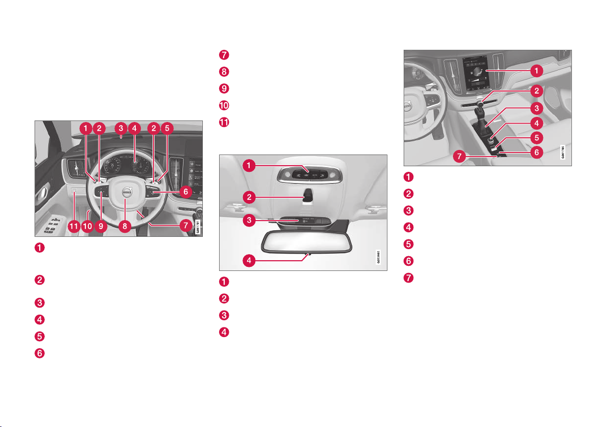
DISPLAYS AND VOICE CONTROL
Instruments and controls in lefthand drive car
The overviews show where the displays and
controls near the driver are located.
Steering wheel and instrument panel
Position lamps, daytime running lights,
dipped beam, main beam, direction indicators, rear fog lamp, resetting the trip meter
Steering wheel paddles for manual gear
changing in an automatic gearbox*
Head-up display*
Driver display
Wipers and washing, rain sensor*
Right-hand steering wheel keypad
Steering wheel adjustment
Horn
Left-hand steering wheel keypad
Bonnet opening
Display lighting, tailgate unlocking/opening*/
closing*, halogen headlamp levelling
Roof console
Front reading lamps and interior lighting
Panorama roof*
Display in roof console, ON CALL button*
Manual dimming of interior rearview mirror
Centre and tunnel console
Centre display
Hazard warning flashers, defrosting, media
Gear selector
Start knob
Drive mode control
Parking brake
Automatic braking when stationary
Driver's door
74
* Option/accessory.
Page 77
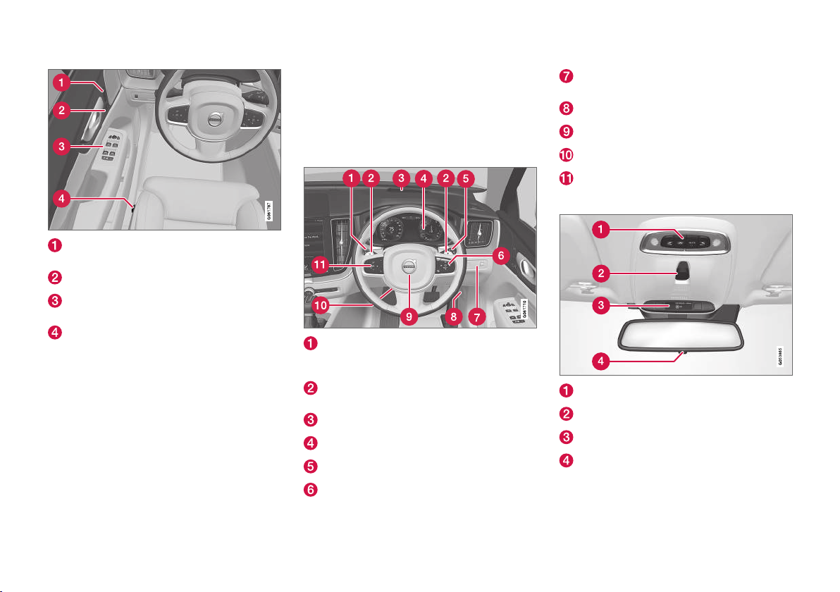
DISPLAYS AND VOICE CONTROL
Memories for power front seat*, door mirror
and head-up display* settings
Central locking
Power windows, door mirrors, electric child
safety lock*
Adjusting front seat
Related information
Manual front seat (p. 176)
•
Adjusting the power* front seat (p. 177)
•
Adjusting the steering wheel (p. 191)
•
Lighting control (p. 144)
•
Starting the car (p. 432)
•
Driver display (p. 77)
•
Overview of centre display (p. 102)
•
Gearbox (p. 446)
•
Instruments and controls in righthand drive car
The overviews show where the displays and
controls near the driver are located.
Steering wheel and instrument panel
Position lamps, daytime running lights,
dipped beam, main beam, direction indicators, rear fog lamp, resetting the trip meter
Steering wheel paddles for manual gear
changing in an automatic gearbox*
Head-up display*
Driver display
Wipers and washing, rain sensor*
Right-hand steering wheel keypad
Display lighting, tailgate unlocking/opening*/
closing*, halogen headlamp levelling
Bonnet opening
Horn
Steering wheel adjustment
Left-hand steering wheel keypad
Roof console
Front reading lamps and interior lighting
Panorama roof*
Display in roof console, ON CALL button*
Manual dimming of interior rearview mirror
Centre and tunnel console
}}
* Option/accessory.
75
Page 78
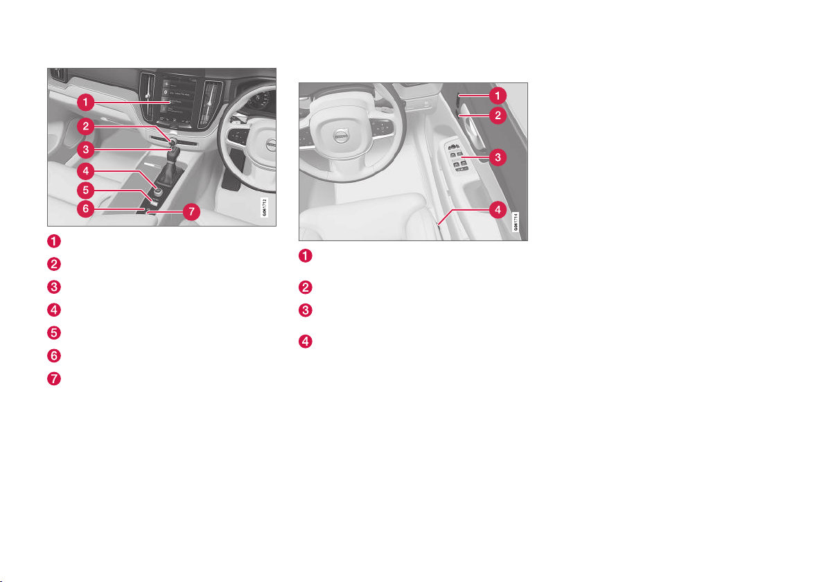
DISPLAYS AND VOICE CONTROL
||
Centre display
Hazard warning flashers, defrosting, media
Gear selector
Start knob
Drive mode control
Parking brake
Automatic braking when stationary
Driver's door
Memories for power front seat*, door mirror
and head-up display* settings
Central locking
Power windows, door mirrors, electric child
safety lock*
Adjusting front seat
Related information
Manual front seat (p. 176)
•
Adjusting the power* front seat (p. 177)
•
Adjusting the steering wheel (p. 191)
•
Lighting control (p. 144)
•
Starting the car (p. 432)
•
Driver display (p. 77)
•
Overview of centre display (p. 102)
•
Gearbox (p. 446)
•
76
* Option/accessory.
Page 79
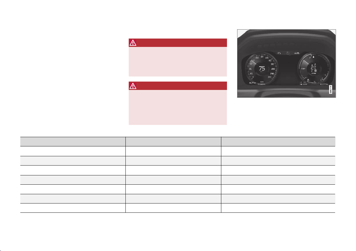
DISPLAYS AND VOICE CONTROL
Driver display
The driver display shows information about the
car and driving.
The driver display contains gauges, indicators and
indicator and warning symbols. The content of
the driver display depends on the car's equipment, settings and which functions are active at
that time.
The driver display is activated as soon as a door
is opened, i.e. in ignition position 0. The driver
display extinguishes after a while if it is not used.
To reactivate it, proceed with one of the following:
Depress the brake pedal.
•
Activate ignition position I.
•
Location in the driver display:
On the left In the middle On the right
Speedometer Indicator and warning symbols
Trip meter Outside temperature gauge Gear shift indicator
Odometer
Cruise control and speed limiter information Messages, in some cases with graphics Fuel gauge
Road Sign Information*
– Charging status Distance to empty tank
– Media player Distance to empty battery
B
Open one of the doors.
•
WARNING
If the driver display should extinguish, not illuminate on activation/start or be fully or partially illegible, the car must not be used. You
should visit a workshop immediately. Volvo
recommends an authorised Volvo workshop.
WARNING
In the event of a fault in the driver display the
information on e.g. brakes, airbags or other
safety systems may not be shown. In which
case, the driver cannot check the status of
the car's systems or receive current warnings
and information.
Clock Drive mode
Door and seatbelt information Hybrid battery gauge
The figure is schematic - parts may vary depending on
car model.
Tachometer/Hybrid gauge
A
* Option/accessory.
}}
77
Page 80
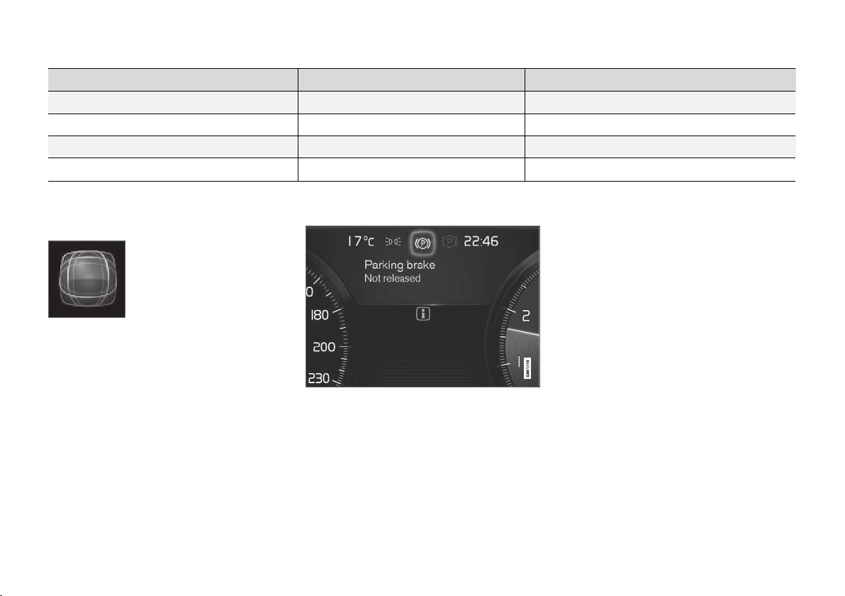
DISPLAYS AND VOICE CONTROL
||
On the left In the middle On the right
–
Navigation map*
Instantaneous fuel consumption
– Phone App menu (activated via steering wheel keypad)
– Voice recognition –
–
A
Depends on drive mode selected.
B
Accumulated mileage.
Compass
A
–
Dynamic symbol
The dynamic symbol in its basic
form.
The centre of the driver display contains a
dynamic symbol that changes appearance for different types of message. An amber or red marker
around the symbol indicates the degree of
severity of a control or warning message.
78
Examples of indicator symbol.
With an animation, the basic shape can be turned
into a graphic showing where a problem is situated, or in order to clarify information.
Related information
Driver display settings (p. 79)
•
Warning symbols in the driver display
•
(p. 89)
Indicator symbols in the driver display
•
(p. 87)
Trip computer (p. 82)
•
Messages in the driver display (p. 98)
•
Handling the application menu in the driver
•
display (p. 97)
* Option/accessory.
Page 81
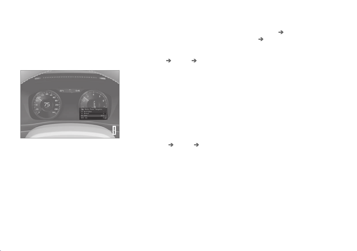
DISPLAYS AND VOICE CONTROL
Driver display settings
Settings for the driver display's display options
can be made via the driver display's application
menu and via the centre display's settings menu.
Settings via the driver display's app menu
The figure is schematic - parts may vary depending on
car model.
The app menu is opened and controlled using
the right-hand keypad on the steering wheel.
In the app menu, you can choose which information is shown on the driver display from
Trip computer
•
media player
•
phone
•
navigation system*.
•
Settings via the centre display
Selecting information type
1.
2. Press
3. Select what should be shown in the back-
Selecting theme
1.
2. Tap on
3. Select a theme (appearance) for the driver
Selecting language
1.
Settings in the centre display's top
Tap on
view.
My Car Displays Driver
Display Information
ground:
Show no information in background
•
Show information for current playing
•
media
Show navigation even if no route is
•
set
Settings in the centre display's top
Tap on
view.
My Car Displays Display
.
Themes
display:
Glass
•
Minimalistic
•
Performance
•
Chrome Rings
•
Tap on
Settings in the centre display's top
view.
.
2. Tap on
These settings are personal and are saved automatically to the active driver profile.
System System Languages and
Units
guage.
> A change will affect the language in all
System Language to select lan-
displays.
Related information
Driver display (p. 77)
•
Handling the application menu in the driver
•
display (p. 97)
Other settings in the centre display's top
•
view (p. 125)
* Option/accessory.
79
Page 82
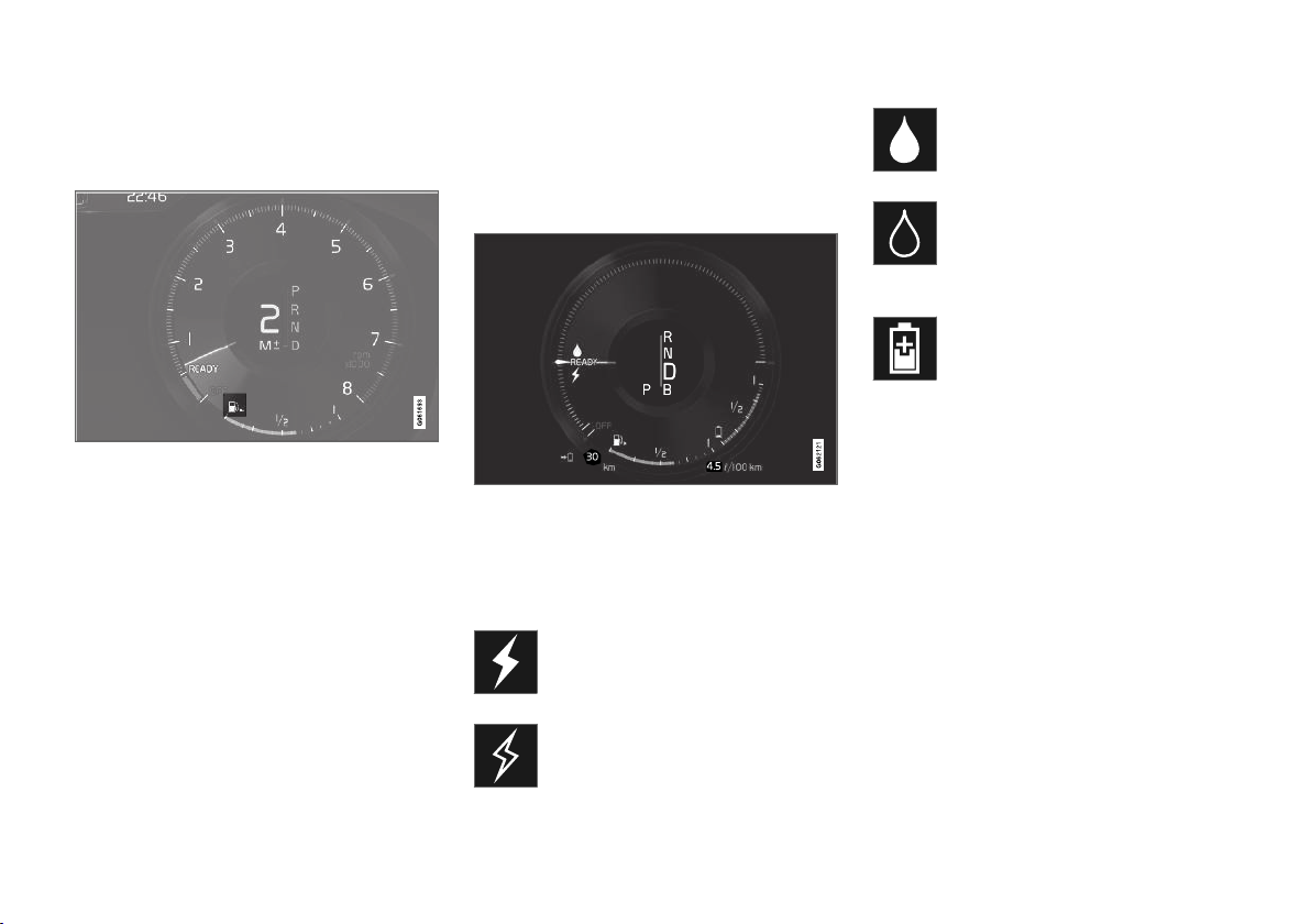
DISPLAYS AND VOICE CONTROL
Fuel gauge
The fuel gauge in the driver display shows the
fuel level in the tank.
The beige zone in the fuel gauge indicates the
quantity of fuel in the tank.
When the fuel level is low and it is soon time to
refuel, the fuel pump symbol illuminates and
changes to amber. The trip computer also indicates the distance to empty tank.
Related information
Driver display (p. 77)
•
Hybrid battery gauge (p. 81)
•
Filling fuel (p. 473)
•
Fuel tank - volume (p. 664)
•
Hybrid gauge
In drive modes Hybrid and Pure, the driver display shows a hybrid gauge that can help the
driver to drive the car in a more energy-efficient
way.
The hybrid gauge shows in different ways the
relationship between how much power is being
taken from the electric motor and how much
power is available.
Symbols in the hybrid gauge
Indicates current level for available
electric motor power. If the symbol is
filled in, it means that the electric
motor is in use.
If the symbol is not filled in, it means
that the electric motor is not in use.
Indicates the power level when the
combustion engine starts. If the symbol
is filled in, it means that the combustion engine is in use.
Indicates the power level when the
internal combustion engine is due to
start. If the symbol is not filled in, it
means that the combustion engine is
not in use.
Indicator that shows that the hybrid
battery is being charged, e.g. if the
brake pedal is gently depressed.
Driver-requested power
The pointer in the hybrid gauge indicates the
amount of engine power requested by the driver
by regulating the accelerator pedal. The higher
the reading on the scale, the more power is
requested by the driver in the current gear. The
marker between the lightning flash and the drop
shows the point at which the internal combustion
engine starts.
80
Page 83
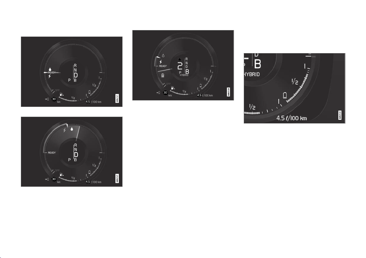
DISPLAYS AND VOICE CONTROL
Example:
The car is started but stationary, no power is requested.
The electric motor cannot supply the amount of engine
power requested and the internal combustion engine
starts.
The car generates current to the battery, the battery is
charged, e.g. when the brake pedal is pressed lightly or
during engine braking down a hill.
Related information
Drive modes (p. 454)
•
Driver display (p. 77)
•
Foot brake (p. 438)
•
Starting and stopping the combustion engine
•
in Twin Engine (p. 453)
Hybrid battery gauge
The hybrid battery gauge shows how much
energy there is in the hybrid battery.
The energy in the hybrid battery is used for the
electric motor, but also to cool or heat the car.
The trip computer calculates an approximate distance for the energy left in the hybrid battery.
}}
81
Page 84
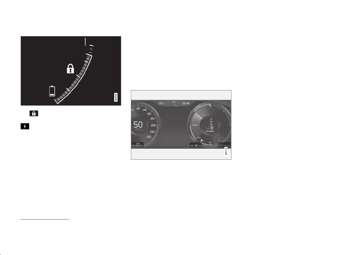
DISPLAYS AND VOICE CONTROL
||
Symbols in the hybrid battery gauge
The symbol in the hybrid battery gauge indicates that the
symbol indicates that the Charge function
is activated.
Hold function is activated, and the
Related information
Driver display (p. 77)
•
Charging the hybrid battery (p. 405)
•
Hold and Charge function (p. 469)
•
Trip computer
The car's trip computer records vales such as
e.g. distance, fuel consumption and average
speed whilst driving.
In order to facilitate fuel-efficient driving, information is recorded about both instantaneous and
average fuel consumption. The information from
the trip computer can be shown in the driver display.
Examples of trip computer information in the driver dis-
1
play.
The following meters are included in the trip
computer:
Trip meter
•
Odometer
•
Instantaneous fuel consumption
•
Distance to empty tank
•
Distance to empty battery
•
Tourist - alternative speedometer
•
Units for distance, speed, etc. can be changed via
system settings in the centre display.
Trip meter
There are two trip meters, TM and TA.
TM can be reset manually and TA is reset auto-
matically if the car is not used for at least four
hours.
The following information is registered while driving:
Mileage
•
Driving time
•
Average speed
•
Average fuel consumption
•
The values apply from the trip meter's latest
reset.
Odometer
The odometer records the car's total mileage.
This value cannot be reset to zero.
Instantaneous fuel consumption
This gauge shows the fuel consumption that the
car has at the moment. The value is updated
approximately every second.
1
The figure is schematic - parts may vary depending on car model.
82
Page 85
Distance to empty tank
The trip computer calculates the
remaining mileage with the fuel available in the tank.
The calculation is based on the average fuel consumption over the last 30 km (20 miles) and the
remaining drivable fuel quantity.
When the gauge shows "----", there is not
enough fuel left to be able to calculate the
remaining mileage. Refuel as soon as possible.
NOTE
There may be a slight deviation if the driving
style has been changed.
An economic driving style generally results in a
longer driving distance.
Distance to empty battery
The approximate distance that can be
driven with the remaining amount of
energy in the hybrid battery is indicated
adjacent to this symbol.
The calculation is based on the average consumption of normally loaded vehicle, during normal driving and taking into account whether the
air conditioning (AC) is switched on or off. When
changing between the
modes, the calculated distance increases since
Hybrid and Pure drive
the
Pure mode has reduced climate settings
(ECO climate).
No guaranteed range on electric power remains
when the gauge shows "----".
NOTE
There may be a slight deviation if the driving
style has been changed.
An economic driving style generally results in a
longer driving distance.
Start value for fully charged hybrid battery
Since it is difficult to anticipate driving style and
other factors that affect the range for electric
operation, Volvo has decided to use a start value
when the car is fully charged. The start value indicates an up-to figure instead of a forecast for the
range for electric operation. The difference in
start value between
the car being allowed to use more energy from
the hybrid battery in Pure mode, as well as that
the car changes over to ECO climate.
Mileage for electric operation
In order to achieve the longest possible mileage
for electric operation, the driver of an electrically
powered car also has to think about energy conservation. The more consumers there are (stereo,
electric heating in windows/mirrors/seats, very
cold air from the climate control system, etc.) that
are active - the shorter the potential mileage.
Hybrid and Pure is due to
DISPLAYS AND VOICE CONTROL
NOTE
In addition to high current take-off in the passenger compartment, sudden acceleration
and braking, high speed, heavy loads, low outside temperature and uphill gradients also
reduce the possible driving distance.
Tourist - alternative speedometer
The alternative digital speedometer makes it easier to drive in countries where speed limit signs
are in a different unit than that shown in the car's
instruments.
The digital speed is then shown in the opposite
unit to that shown in the analogue speedometer.
If the analogue speedometer is graduated in
mph, the digital speedometer shows the corresponding speed in km/h and vice versa.
Related information
Show trip data in the driver display (p. 84)
•
Resetting the trip meter (p. 85)
•
Show trip statistics in the centre display
•
(p. 85)
Driver display (p. 77)
•
Changing system units (p. 125)
•
83
Page 86
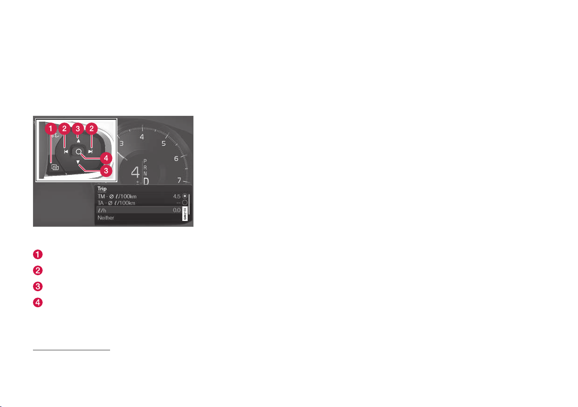
DISPLAYS AND VOICE CONTROL
Show trip data in the driver display
The trip computer's recorded and calculated values can be shown in the driver display.
The values are saved in a trip computer app. Via
the app menu, you can choose which information
is shown on the driver display.
Open and navigate in the app menu2 using the righthand steering wheel keypad.
App menu
Left/right
Up/down
Confirm
2
The figure is schematic - parts may vary depending on car model.
1. Open the app menu in the driver display by
pressing (1).
(It is not possible to open the app menu
while there is an unacknowledged message
in the driver display. The message first has to
be confirmed by pressing the O button (4)
before the app menu can be opened.)
2. Navigate to the trip computer app to left or
right with (2).
> The top four menu rows show measured
values for trip meter TM. The next four
menu rows show measured values for trip
meter TA. Scroll up or down in the list with
(3).
3. Scroll down to the option buttons to select
which information to show in the driver display:
Odometer
•
Distance to empty tank
•
Distance to empty battery
•
Tourist (alternative speedometer)
•
Mileage for trip meter TM, TA, or no dis-
•
play of mileage
Instantaneous fuel consumption, average
•
consumption for TM or TA, alternatively,
no display of fuel consumption
Select or deselect an option with the O button (4). The change is made immediately.
Related information
Trip computer (p. 82)
•
Resetting the trip meter (p. 85)
•
84
Page 87
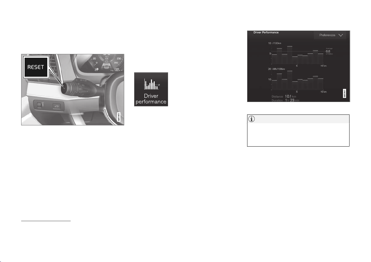
DISPLAYS AND VOICE CONTROL
Resetting the trip meter
Reset the trip meter using the left-hand stalk
switch.
Reset all information in trip meter TM (i.e.
–
mileage, average consumption, average
speed and driving time) with a long press on
the RESET button on the left-hand stalk
switch.
A short press on the RESET button resets
only the mileage.
The trip meter TA can only be reset automatically
when the car has not been used for four or more
hours.
Related information
Trip computer (p. 82)
•
Show trip statistics in the centre display
Trip statistics from the trip computer are displayed graphically in the centre display and provide an overview that facilitates more fuel-efficient driving.
Open the Driver performance
app in app view in order to
show the trip statistics.
Each bar in the diagram symbolises a distance of 1, 10 or
100 km, alternatively miles. The
bars are filled in from the right as driving progresses. The bar on the far right shows the value
for the current distance.
The average fuel consumption and total driving
time are calculated since the last time the trip
statistics were reset.
Fuel and electricity consumption are shown in
separate graphs. Electricity consumption is "net"
consumption, i.e. energy consumed minus regenerated energy created during braking.
Trip statistics from the trip computer3.
NOTE
When driving with electric operation, fuel consumption can be indicated in the trip statistics
if the additional heater4 is running.
Related information
Settings for trip statistics (p. 86)
•
Trip computer (p. 82)
•
3
The figure is schematic - parts may vary depending on car model.
4
Applicable to fuel-driven auxiliary heater.
85
Page 88
DISPLAYS AND VOICE CONTROL
Settings for trip statistics
Reset or adjust settings for trip statistics.
1.
Open the
view in order to show the trip statistics.
2.
Press
•
•
•
Trip statistics, calculated average consumption and total driving time are always reset
simultaneously.
Units for distance, speed, etc. can be changed via
system settings in the centre display.
Related information
Show trip statistics in the centre display
•
(p. 85)
Trip computer (p. 82)
•
Resetting the trip meter (p. 85)
•
Driver performance app in app
Preferences to
change graph scale. Select resolution 1,
10 or 100 km/miles for the bar.
reset data after every trip. Performed
when the car has been stationary for more
than 4 hours.
reset data for the current trip.
Date and time
The clock is shown in both the driver display and
the centre display.
Clock location
In certain situations, messages and information
may cover the clock in the driver display.
In the centre display, the clock is located at the
top right of the status bar.
Date and time settings
–
Select Settings System Date and
Time
in the centre display's top view to
change settings for time and date format.
Adjust the date and time by pressing the up
or down arrow on the touch screen.
Automatic time for cars with GPS
When the car is equipped with a navigation system,
Auto Time can be selected. The time zone
is then adjusted automatically based on the location of the car. For certain types of navigation
systems, the current location (country) must also
be set to obtain the right time zone. If
is not selected, time and data are adjusted with
arrow up or arrow down on the touch screen.
Summer time
In certain countries, it is possible to select the
Auto Daylight Saving Time setting for auto-
matic setting of summer time. For other countries, the
selected manually.
Daylight Saving Time setting can be
Auto Time
Related information
Driver display (p. 77)
•
Other settings in the centre display's top
•
view (p. 125)
86
Page 89
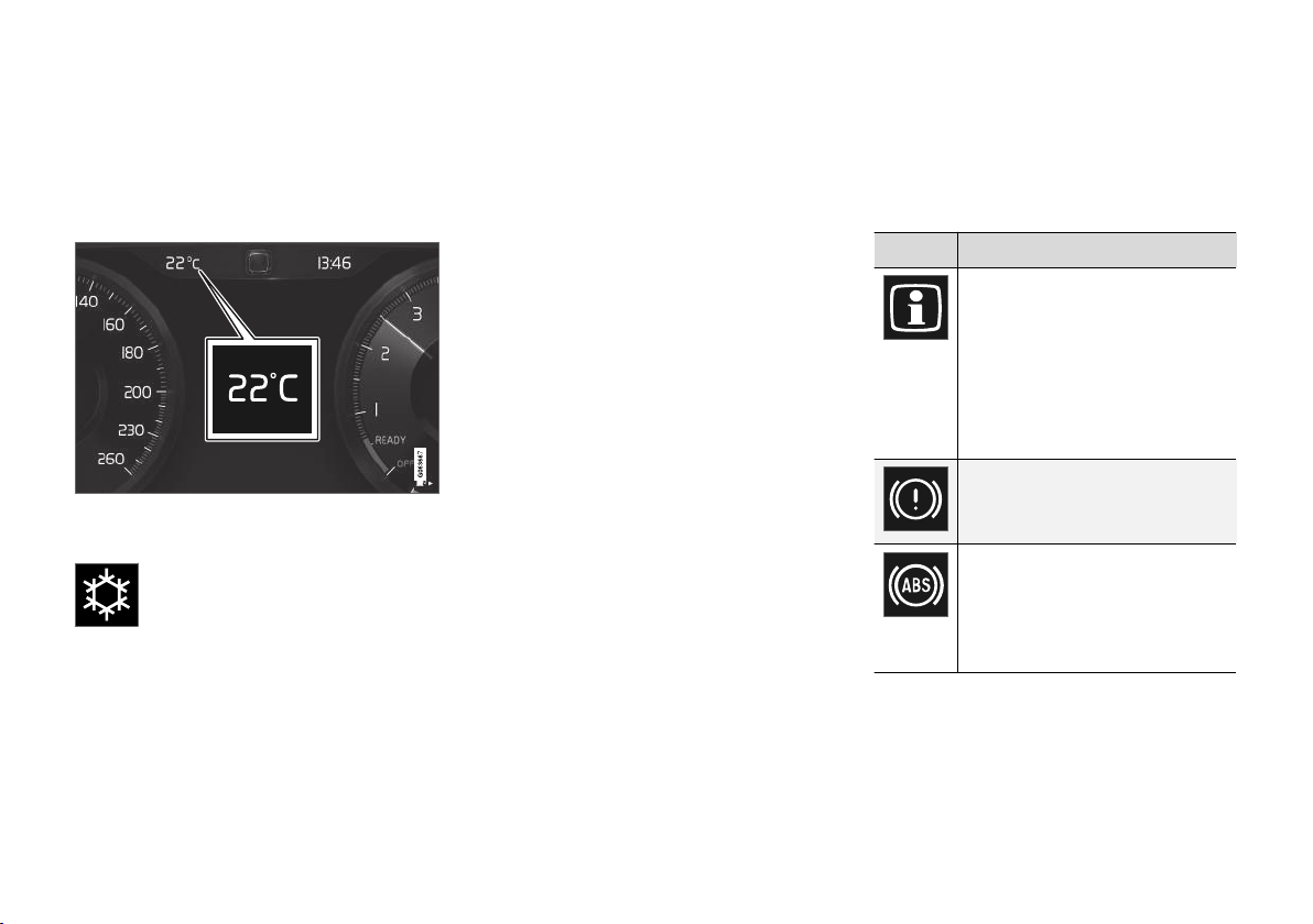
DISPLAYS AND VOICE CONTROL
Outside temperature gauge
The outside temperature is shown in the driver
display.
A sensor detects the temperature outside of the
car.
If the car has been stationary, the gauge may display a temperature reading that is too high.
When the outside temperature is in the
range –5 °C to +2 °C (23 °F to 36 °F),
a snowflake symbol lights up that
warns of potentially slippery conditions.
The symbol is also illuminated briefly in the headup display*, if the car is equipped with one.
Change the unit for the temperature gauge, etc.
via system settings in the centre display's top
view.
Related information
Driver display (p. 77)
•
Changing system units (p. 125)
•
Indicator symbols in the driver display
The indicator symbols alert the driver that a function is activated, that a system is operating, or
that a fault or abnormal condition has occurred.
Symbol Specification
Information, read display text
When one of the car's systems
does not behave as intended, this
information symbol illuminates and
a text appears on the driver display.
The information symbol can also
illuminate in conjunction with other
symbols.
Fault in brake system
The symbol lights up when there is
a fault in the parking brake.
ABS fault
If this symbol illuminates then the
system is not working. The car's
regular brake system continues to
work, but without the ABS function.
* Option/accessory.
}}
87
Page 90
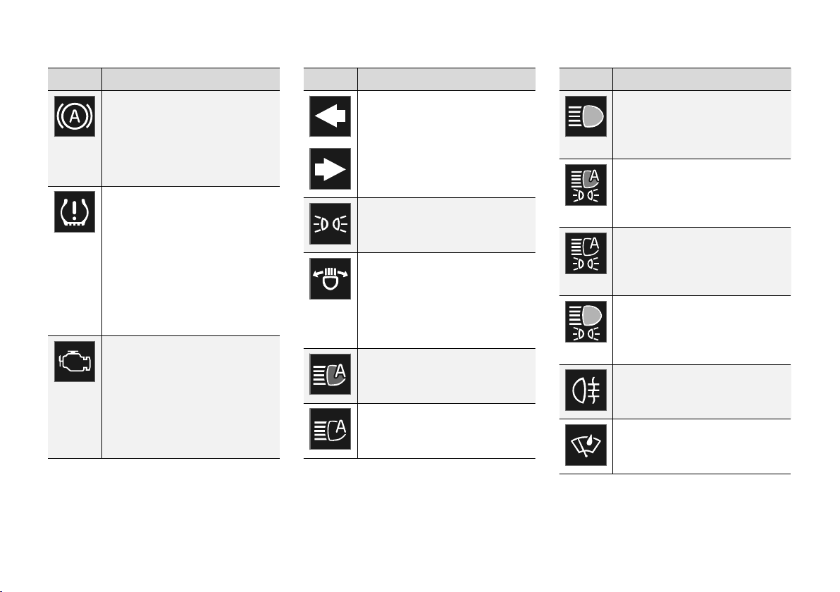
DISPLAYS AND VOICE CONTROL
||
Symbol Specification
Automatic brake on
The symbol illuminates when the
function is activated and the foot
brake or parking brake is acting.
The brake holds the car stationary
when it has stopped.
Tyre pressure system
The symbol illuminates when tyre
pressure is too low. If there is a
fault in the tyre pressure system,
the symbol will flash for approx. 1
minute and then illuminate with a
constant glow. This may be
because the system cannot detect
or warn of low tyre pressure as
intended.
Emissions system
If the symbol illuminates after the
engine has been started then it
may be due to a fault in the car's
emissions system. Drive to a workshop for checking. Volvo recommends that an authorised Volvo
workshop is contacted.
Symbol Specification
Left and right-hand direction
indicator
The symbols flash when the direction indicators are used.
Position lamps
The symbol lights up when the
position lamps are switched on.
Fault in the headlamp system
The symbol illuminates if a fault
has occurred in the ABL function
(Active Bending Lights) or if
another fault has occurred in the
headlamp system.
Active main beam on
The symbol lights up blue when the
automatic main beam is on.
Active main beam off
The symbol lights up white when
the automatic main beam is off.
Symbol Specification
Main beam On
The symbol illuminates when main
beam is on and with main beam
flash.
Active main beam on
The symbol lights up blue when
active main beam is on. Position
lamps are switched on.
Active main beam off
The symbol lights up white when
active main beam is off. Position
lamps are switched on.
Main beam On
The symbol lights up when main
beam and the position lamps are
switched on.
Rear fog lamp on
This symbol illuminates when the
rear fog lamp is switched on.
Rain sensor on
This symbol illuminates when the
rain sensor is on.
88
Page 91
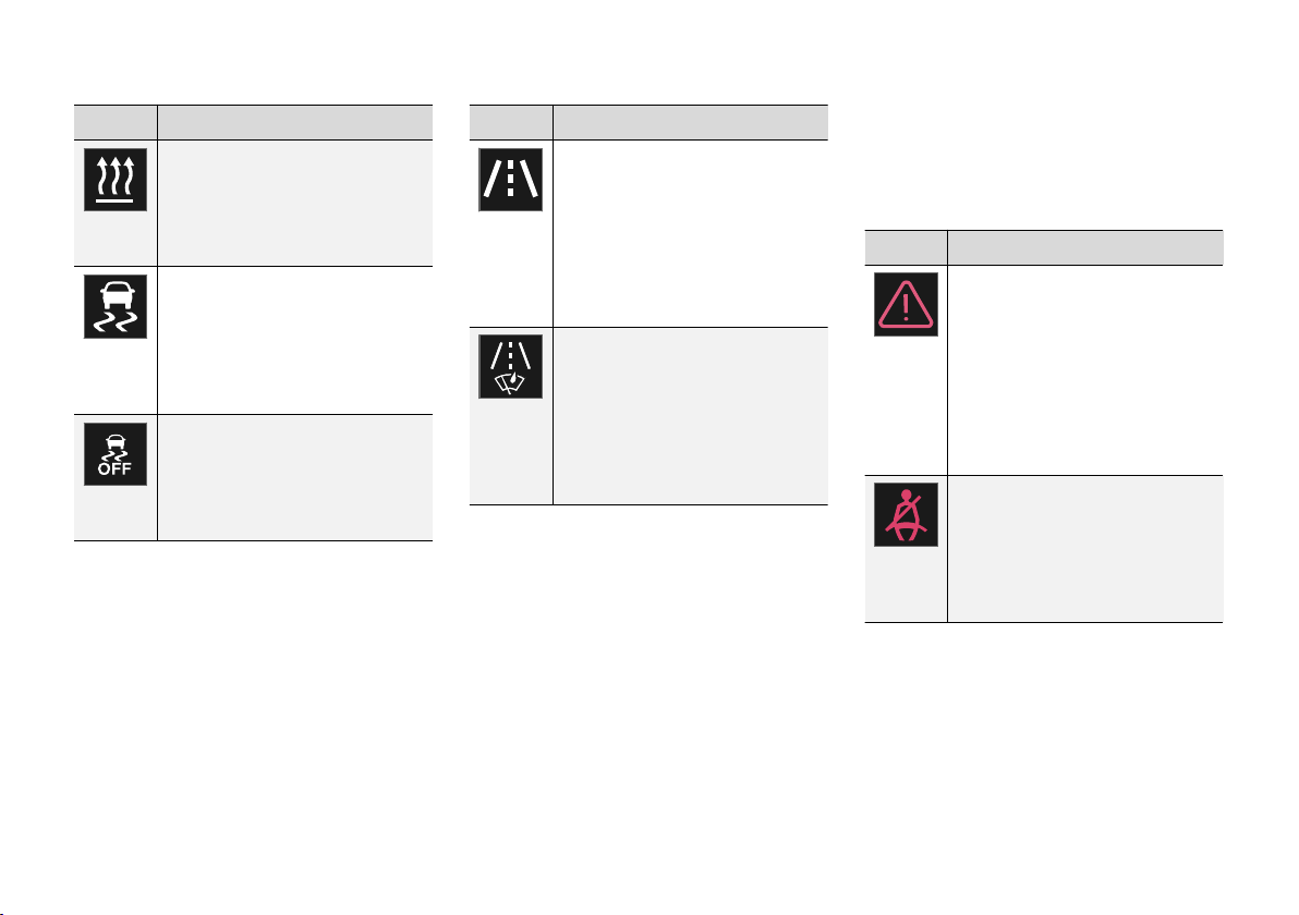
DISPLAYS AND VOICE CONTROL
Symbol Specification
Preconditioning on
The symbol illuminates when the
engine block and passenger compartment heater/air conditioning
are preconditioning the car.
Stability system
A flashing symbol indicates that
the stability system is operating. If
the symbol illuminates with constant glow then there is a fault in
the system.
Stability system, sport mode
The symbol illuminates when the
sport mode is activated. Sport
mode allows for a more active driving experience.
Symbol Specification
Lane assistance
White symbol: Lane assistance is
on and road lines are detected.
Grey symbol: Lane assistance is on
but road lines are not detected.
Amber symbol: Lane assistance
warns/intervenes.
Lane assistance and rain sensor
White symbol: Lane assistance is
on and road lines are detected.
Rain sensor is on.
Grey symbol: Lane assistance is on
but road lines are not detected.
Rain sensor is on.
Related information
Driver display (p. 77)
•
Warning symbols in the driver display
•
(p. 89)
Warning symbols in the driver
display
The warning symbols alert the driver that an
important function is activated or that a serious
fault or condition exists.
Symbol Specification
Warning
The red warning symbol illuminates
when a fault has been indicated
which could affect the safety or
drivability of the car. An explanatory
text is shown on the driver display
at the same time. The warning
symbol can also illuminate in conjunction with other symbols.
Seatbelt reminder
This symbol illuminates or flashes if
someone in a front seat has not
put on their seatbelt or if someone
in a rear seat has taken off their
seatbelt.
}}
89
Page 92
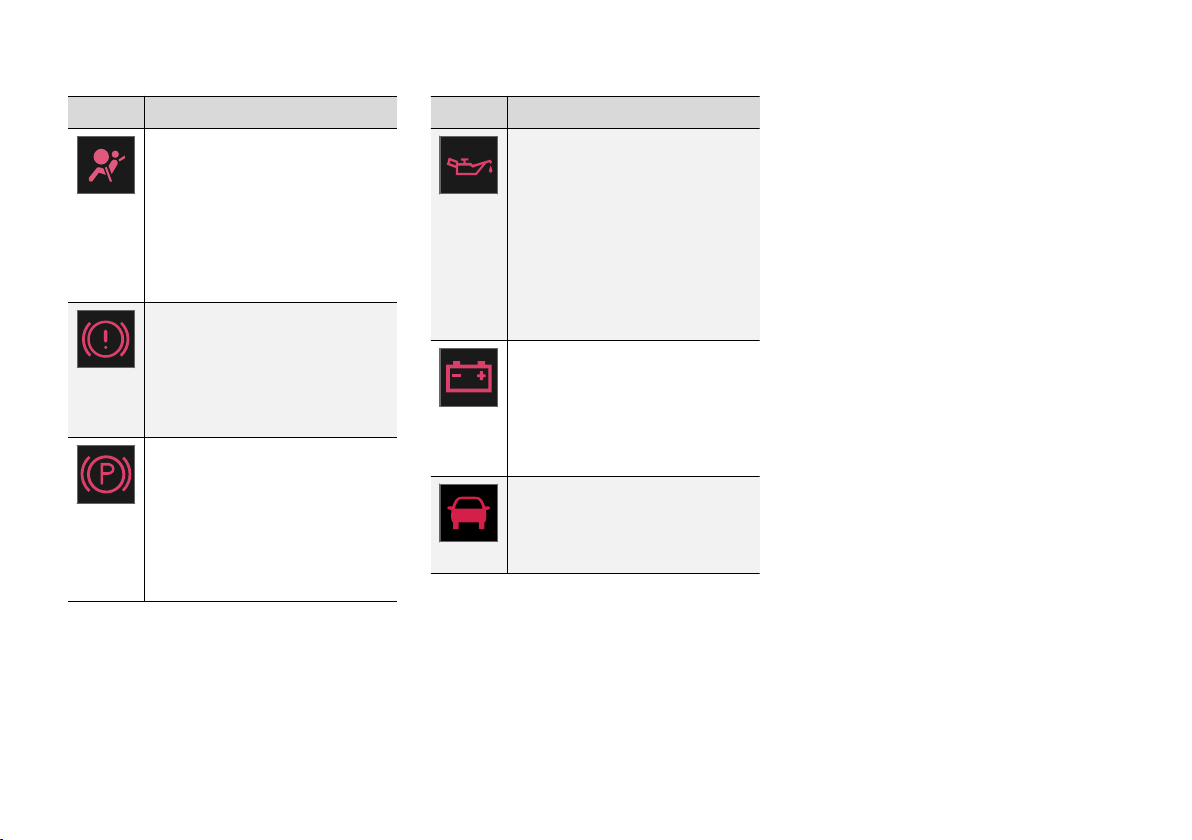
DISPLAYS AND VOICE CONTROL
||
Symbol Specification
Airbags
If the symbol remains illuminated or
illuminates while driving, a fault has
been detected in one of the car's
safety systems. Read the message
in the driver display. Volvo recommends that an authorised Volvo
workshop is contacted.
Fault in brake system
If this symbol illuminates, the brake
fluid level may be too low. Visit the
nearest authorised workshop to
have the brake fluid level checked
and rectified.
Parking brake applied
This symbol illuminates with a constant glow when the parking brake
is applied.
A flashing symbol means that a
fault has arisen. Read the message
in the driver display.
Symbol Specification
Low oil pressure
If this symbol illuminates during
driving then the engine's oil pressure is too low. Stop the engine
immediately and check the engine
oil level, top up if necessary. If the
symbol illuminates and the oil level
is normal, contact a workshop.
Volvo recommends that an authorised Volvo workshop is contacted.
Alternator not charging
This symbol illuminates during driving if a fault has occurred in the
electrical system. Visit a workshop.
Volvo recommends that an authorised Volvo workshop is contacted.
Collision risk
City Safety warns of a risk of collision with other vehicles, pedestrians, cyclists or large animals.
Related information
Indicator symbols in the driver display (p. 87)
•
Driver display (p. 77)
•
License agreement for the driver display
A license is an agreement for the right to operate a certain activity or the right to use someone
else's entitlement according to the terms and
conditions in the agreement. The following text is
Volvo's agreement with the manufacturer or
developer.
90
Page 93

DISPLAYS AND VOICE CONTROL
Boost Software License 1.0
Permission is hereby granted, free of charge, to
any person or organization obtaining a copy of
the software and accompanying documentation
covered by this license (the "Software") to use,
reproduce, display, distribute, execute, and
transmit the Software, and to prepare derivative
works of the Software, and to permit third-parties
to whom the Software is furnished to do so, all
subject to the following: The copyright notices in
the Software and this entire statement, including
the above license grant, this restriction and the
following disclaimer, must be included in all
copies of the Software, in whole or in part, and all
derivative works of the Software, unless such
copies or derivative works are solely in the form
of machine-executable object code generated by
a source language processor.
THE SOFTWARE IS PROVIDED "AS IS",
WITHOUT WARRANTY OF ANY KIND,
EXPRESS OR IMPLIED, INCLUDING BUT NOT
LIMITED TO THE WARRANTIES OF
MERCHANTABILITY, FITNESS FOR A
PARTICULAR PURPOSE, TITLE AND NONINFRINGEMENT. IN NO EVENT SHALL THE
COPYRIGHT HOLDERS OR ANYONE
DISTRIBUTING THE SOFTWARE BE LIABLE
FOR ANY DAMAGES OR OTHER LIABILITY,
WHETHER IN CONTRACT, TORT OR
OTHERWISE, ARISING FROM, OUT OF OR IN
CONNECTION WITH THE SOFTWARE OR THE
USE OR OTHER DEALINGS IN THE
SOFTWARE.
BSD 4-clause "Original" or "Old" License
Copyright (c) 1982, 1986, 1990, 1991, 1993
The Regents of the University of California. All
rights reserved.
Redistribution and use in source and binary
forms, with or without modification, are permitted
provided that the following conditions are met:
1. Redistributions of source code must retain
the above copyright notice, this list of
conditions and the following disclaimer.
2. Redistributions in binary form must
reproduce the above copyright notice, this list
of conditions and the following disclaimer in
the documentation and/or other materials
provided with the distribution.
3. All advertising materials mentioning features
or use of this software must display the
following acknowledgement: This product
includes software developed by the
University of California, Berkeley and its
contributors.
4. Neither the name of the University nor the
names of its contributors may be used to
endorse or promote products derived from
this software without specific prior written
permission.
THIS SOFTWARE IS PROVIDED BY THE
REGENTS AND CONTRIBUTORS ``AS IS'' AND
ANY EXPRESS OR IMPLIED WARRANTIES,
INCLUDING, BUT NOT LIMITED TO, THE
IMPLIED WARRANTIES OF MERCHANTABILITY
AND FITNESS FOR A PARTICULAR PURPOSE
ARE DISCLAIMED. IN NO EVENT SHALL THE
REGENTS OR CONTRIBUTORS BE LIABLE
FOR ANY DIRECT, INDIRECT, INCIDENTAL,
SPECIAL, EXEMPLARY, OR CONSEQUENTIAL
DAMAGES (INCLUDING, BUT NOT LIMITED TO,
PROCUREMENT OF SUBSTITUTE GOODS OR
SERVICES; LOSS OF USE, DATA, OR PROFITS;
OR BUSINESS INTERRUPTION) HOWEVER
CAUSED AND ON ANY THEORY OF LIABILITY,
WHETHER IN CONTRACT, STRICT LIABILITY,
OR TORT (INCLUDING NEGLIGENCE OR
OTHERWISE) ARISING IN ANY WAY OUT OF
THE USE OF THIS SOFTWARE, EVEN IF
ADVISED OF THE POSSIBILITY OF SUCH
DAMAGE.
}}
91
Page 94

DISPLAYS AND VOICE CONTROL
||
BSD 3-clause "New" or "Revised" License
Copyright (c) 2011-2014, Yann Collet.
Redistribution and use in source and binary
forms, with or without modification, are permitted
provided that the following conditions are met:
1. Redistributions of source code must retain
the above copyright notice, this list of
conditions and the following disclaimer.
2. Redistributions in binary form must
reproduce the above copyright notice, this list
of conditions and the following disclaimer in
the documentation and/or other materials
provided with the distribution.
3. Neither the name of the organisation nor the
names of its contributors may be used to
endorse or promote products derive from this
software without specific prior written
permission.
THIS SOFTWARE IS PROVIDED BY THE
COPYRIGHT HOLDERS AND CONTRIBUTORS
"AS IS" AND ANY EXPRESS OR IMPLIED
WARRANTIES, INCLUDING, BUT NOT LIMITED
TO, THE IMPLIED WARRANTIES OF
MERCHANTABILITY AND FITNESS FOR A
PARTICULAR PURPOSE ARE DISCLAIMED. IN
NO EVENT SHALL THE COPYRIGHT HOLDER
OR CONTRIBUTORS BE LIABLE FOR ANY
DIRECT, INDIRECT, INCIDENTAL, SPECIAL,
EXEMPLARY, OR CONSEQUENTIAL DAMAGES
(INCLUDING, BUT NOT LIMITED TO,
PROCUREMENT OF SUBSTITUTE GOODS OR
SERVICES; LOSS OF USE, DATA, OR PROFITS;
OR BUSINESS INTERRUPTION) HOWEVER
CAUSED AND ON ANY THEORY OF LIABILITY,
WHETHER IN CONTRACT, STRICT LIABILITY,
OR TORT (INCLUDING NEGLIGENCE OR
OTHERWISE) ARISING IN ANY WAY OUT OF
THE USE OF THIS SOFTWARE, EVEN IF
ADVISED OF THE POSSIBILITY OF SUCH
DAMAGE.
BSD 2-clause “Simplified” license
Copyright (c) <YEAR>, <OWNER> All rights
reserved.
Redistribution and use in source and binary
forms, with or without modification, are permitted
provided that the following conditions are met:
1. Redistributions of source code must retain
the above copyright notice, this list of
conditions and the following disclaimer.
2. Redistributions in binary form must
reproduce the above copyright notice, this list
of conditions and the following disclaimer in
the documentation and/or other materials
provided with the distribution.
THIS SOFTWARE IS PROVIDED BY THE
COPYRIGHT HOLDERS AND CONTRIBUTORS
"AS IS" AND ANY EXPRESS OR IMPLIED
WARRANTIES, INCLUDING, BUT NOT LIMITED
TO, THE IMPLIED WARRANTIES OF
MERCHANTABILITY AND FITNESS FOR A
PARTICULAR PURPOSE ARE DISCLAIMED. IN
NO EVENT SHALL THE COPYRIGHT OWNER
OR CONTRIBUTORS BE LIABLE FOR ANY
DIRECT, INDIRECT, INCIDENTAL, SPECIAL,
EXEMPLARY, OR CONSEQUENTIAL DAMAGES
(INCLUDING, BUT NOT LIMITED TO,
PROCUREMENT OF SUBSTITUTE GOODS OR
SERVICES; LOSS OF USE, DATA, OR PROFITS;
OR BUSINESS INTERRUPTION) HOWEVER
CAUSED AND ON ANY THEORY OF LIABILITY,
WHETHER IN CONTRACT, STRICT LIABILITY,
OR TORT (INCLUDING NEGLIGENCE OR
OTHERWISE) ARISING IN ANY WAY OUT OF
THE USE OF THIS SOFTWARE, EVEN IF
ADVISED OF THE POSSIBILITY OF SUCH
DAMAGE.
The views and conclusions contained in the
software and documentation are those of the
authors and should not be interpreted as
representing official policies, either expressed or
implied, of the FreeBSD Project.
92
Page 95

DISPLAYS AND VOICE CONTROL
FreeType Project License
1. 1 Copyright 1996-1999 by David Turner,
Robert Wilhelm, and Werner Lemberg
Introduction The FreeType Project is
distributed in several archive packages; some
of them may contain, in addition to the
FreeType font engine, various tools and
contributions which rely on, or relate to, the
FreeType Project. This license applies to all
files found in such packages, and which do
not fall under their own explicit license. The
license affects thus the FreeType font
engine, the test programs, documentation
and makefiles, at the very least. This license
was inspired by the BSD, Artistic, and IJG
(Independent JPEG Group) licenses, which
all encourage inclusion and use of free
software in commercial and freeware
products alike. As a consequence, its main
points are that: o We don't promise that this
software works. However, we are be
interested in any kind of bug reports. (`as is'
distribution) o You can use this software for
whatever you want, in parts or full form,
without having to pay us. (`royalty-free'
usage) o You may not pretend that you wrote
this software. If you use it, or only parts of it,
in a program, you must acknowledge
somewhere in your documentation that
you've used the FreeType code. (`credits')
We specifically permit and encourage the
inclusion of this software, with or without
modifications, in commercial products,
provided that all warranty or liability claims
are assumed by the product vendor. Legal
Terms 0. Definitions Throughout this license,
the terms `package', `FreeType Project', and
`FreeType archive' refer to the set of files
originally distributed by the authors (David
Turner, Robert Wilhelm, and Werner
Lemberg) as the `FreeType project', be they
named as alpha, beta or final release. `You'
refers to the licensee, or person using the
project, where `using' is a generic term
including compiling the project's source code
as well as linking it to form a `program' or
`executable'. This program is referred to as `a
program using the FreeType engine'. This
license applies to all files distributed in the
original FreeType archive, including all source
code, binaries and documentation, unless
otherwise stated in the file in its original,
unmodified form as distributed in the original
archive. If you are unsure whether or not a
particular file is covered by this license, you
must contact us to verify this. The FreeType
project is copyright (C) 1996-1999 by David
Turner, Robert Wilhelm, and Werner
Lemberg. All rights reserved except as
specified below. 1. No Warranty THE
FREETYPE ARCHIVE IS PROVIDED `AS IS'
WITHOUT WARRANTY OF ANY KIND,
EITHER EXPRESSED OR IMPLIED,
INCLUDING, BUT NOT LIMITED TO,
WARRANTIES OF MERCHANTABILITY AND
FITNESS FOR A PARTICULAR PURPOSE.
IN NO EVENT WILL ANY OF THE
AUTHORS OR COPYRIGHT HOLDERS BE
LIABLE FOR ANY DAMAGES CAUSED BY
THE USE OR THE INABILITY TO USE, OF
THE FREETYPE PROJECT. As you have not
signed this license, you are not required to
accept it. However, as the FreeType project
is copyrighted material, only this license, or
another one contracted with the authors,
grants you the right to use, distribute, and
modify it. Therefore, by using, distributing, or
modifying the FreeType project, you indicate
that you understand and accept all the terms
of this license.
2. Redistribution Redistribution and use in
source and binary forms, with or without
modification, are permitted provided that the
following conditions are met: o Redistribution
of source code must retain this license file
(`licence.txt') unaltered; any additions,
deletions or changes to the original files
must be clearly indicated in accompanying
documentation. The copyright notices of the
unaltered, original files must be preserved in
all copies of source files. o Redistribution in
binary form must provide a disclaimer that
states that the software is based in part of
the work of the FreeType Team, in the
distribution documentation. We also
encourage you to put an URL to the
FreeType web page in your documentation,
though this isn't mandatory. These conditions
apply to any software derived from or based
}}
93
Page 96

DISPLAYS AND VOICE CONTROL
||
on the FreeType code, not just the
unmodified files. If you use our work, you
must acknowledge us. However, no fee need
be paid to us.
3. Advertising The names of FreeType's authors
and contributors may not be used to endorse
or promote products derived from this
software without specific prior written
permission. We suggest, but do not require,
that you use one or more of the following
phrases to refer to this software in your
documentation or advertising materials:
`FreeType Project', `FreeType Engine',
`FreeType library', or `FreeType Distribution'.
4. Contacts There are two mailing lists related
to FreeType: o [email protected]
Discusses general use and applications of
FreeType, as well as future and wanted
additions to the library and distribution. If you
are looking for support, start in this list if you
haven't found anything to help you in the
documentation. o [email protected]
Discusses bugs, as well as engine internals,
design issues, specific licenses, porting, etc.
o http://www.freetype.org Holds the current
FreeType web page, which will allow you to
download our latest development version and
read online documentation. You can also
contact us individually at: David Turner
Lemberg <[email protected]
Libpng License
This copy of the libpng notices is provided for
your convenience. In case of any discrepancy
between this copy and the notices in the file
png.h that is included in the libpng distribution,
the latter shall prevail.
COPYRIGHT NOTICE, DISCLAIMER, and
LICENSE:
If you modify libpng you may insert additional
notices immediately following this sentence.
libpng versions 1.0.7, July 1, 2000, through
1.0.13, April 15, 2002, are Copyright (c)
2000-2002 Glenn Randers-Pehrson and are
distributed according to the same disclaimer and
license as libpng-1.0.6 with the following
individuals added to the list of Contributing
Authors
Simon-Pierre Cadieux
Eric S. Raymond
Gilles Vollant
and with the following additions to the disclaimer:
There is no warranty against interference with
your enjoyment of the library or against
infringement. There is no warranty that our efforts
or the library will fulfill any of your particular
purposes or needs. This library is provided with all
faults, and the entire risk of satisfactory quality,
libpng versions 0.97, January 1998, through
1.0.6, March 20, 2000, are Copyright (c) 1998,
1999 Glenn Randers-Pehrson, and are
distributed according to the same disclaimer and
license as libpng-0.96, with the following
individuals added to the list of Contributing
Authors:
Tom Lane
Glenn Randers-Pehrson
Willem van Schaik
libpng versions 0.89, June 1996, through 0.96,
May 1997, are Copyright (c) 1996, 1997
Andreas Dilger Distributed according to the same
disclaimer and license as libpng-0.88, with the
following individuals added to the list of
Contributing Authors:
John Bowler
Kevin Bracey
Sam Bushell
Magnus Holmgren
Greg Roelofs
Tom Tanner
libpng versions 0.5, May 1995, through 0.88,
January 1996, are Copyright (c) 1995, 1996 Guy
Eric Schalnat, Group 42, Inc.
performance, accuracy, and effort is with the user.
>
94
Page 97

DISPLAYS AND VOICE CONTROL
For the purposes of this copyright and license,
"Contributing Authors" is defined as the following
set of individuals:
Andreas Dilger
Dave Martindale
Guy Eric Schalnat
Paul Schmidt
Tim Wegner
The PNG Reference Library is supplied "AS IS".
The Contributing Authors and Group 42, Inc.
disclaim all warranties, expressed or implied,
including, without limitation, the warranties of
merchantability and of fitness for any purpose.
The Contributing Authors and Group 42, Inc.
assume no liability for direct, indirect, incidental,
special, exemplary, or consequential damages,
which may result from the use of the PNG
Reference Library, even if advised of the
possibility of such damage.
Permission is hereby granted to use, copy,
modify, and distribute this source code, or
portions hereof, for any purpose, without fee,
subject to the following restrictions:
1. The origin of this source code must not be
misrepresented.
2. Altered versions must be plainly marked as
such and must not be misrepresented as
being the original source.
3. This Copyright notice may not be removed or
altered from any source or altered source
distribution.
The Contributing Authors and Group 42, Inc.
specifically permit, without fee, and encourage
the use of this source code as a component to
supporting the PNG file format in commercial
products. If you use this source code in a product,
acknowledgment is not required but would be
appreciated.
A "png_get_copyright" function is available, for
convenient use in "about" boxes and the like:
printf("%s",png_get_copyright(NULL));
Also, the PNG logo (in PNG format, of course) is
supplied in the files "pngbar.png" and
"pngbar.jpg (88x31) and "pngnow.png" (98x31).
Libpng is OSI Certified Open Source Software.
OSI Certified Open Source is a certification mark
of the Open Source Initiative.
Glenn Randers-Pehrson [email protected]
April 15, 2002
MIT License
Copyright (c) <year> <copyright holders>
Permission is hereby granted, free of charge, to
any person obtaining a copy of this software and
associated documentation files (the "Software"),
to deal in the Software without restriction,
including without limitation the rights to use,
copy, modify, merge, publish, distribute,
sublicense, and/or sell copies of the Software,
and to permit persons to whom the Software is
furnished to do so, subject to the following
conditions:
The above copyright notice and this permission
notice shall be included in all copies or
substantial portions of the Software.
THE SOFTWARE IS PROVIDED "AS IS",
WITHOUT WARRANTY OF ANY KIND,
EXPRESS OR IMPLIED, INCLUDING BUT NOT
LIMITED TO THE WARRANTIES OF
MERCHANTABILITY, FITNESS FOR A
PARTICULAR PURPOSE AND
NONINFRINGEMENT. IN NO EVENT SHALL
THE AUTHORS OR COPYRIGHT HOLDERS BE
LIABLE FOR ANY CLAIM, DAMAGES OR
OTHER LIABILITY, WHETHER IN AN ACTION
OF CONTRACT, TORT OR OTHERWISE,
ARISING FROM, OUT OF OR IN CONNECTION
WITH THE SOFTWARE OR THE USE OR
OTHER DEALINGS IN THE SOFTWARE.
}}
95
Page 98
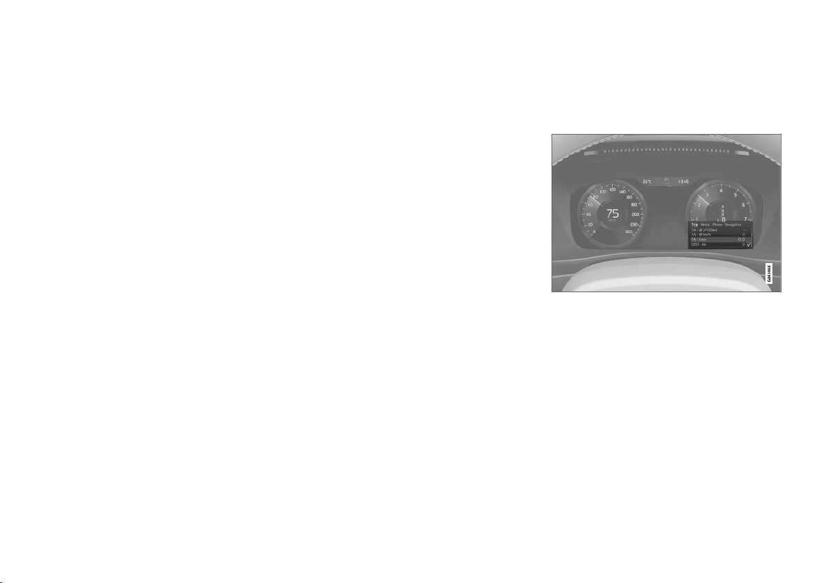
DISPLAYS AND VOICE CONTROL
||
zlib License
The zlib/libpng License Copyright (c) <year>
<copyright holders>
This software is provided 'as-is', without any
express or implied warranty. In no event will the
authors be held liable for any damages arising
from the use of this software.
Permission is granted to anyone to use this
software for any purpose, including commercial
applications, and to alter it and redistribute it
freely, subject to the following restrictions:
1. The origin of this software must not be
misrepresented; you must not claim that you
wrote the original software. If you use this
software in a product, an acknowledgment in
the product documentation would be
appreciated but is not required.
2. Altered source versions must be plainly
marked as such, and must not be
misrepresented as being the original
software.
3. This notice may not be removed or altered
from any source distribution.
SGI Free Software B License Version 2.0.
SGI FREE SOFTWARE LICENSE B (Version 2.0,
Sept. 18, 2008)
Copyright (C) [dates of first publication] Silicon
Graphics, Inc. All Rights Reserved. Permission is
hereby granted, free of charge, to any person
obtaining a copy of this software and associated
documentation files (the "Software"), to deal in
the Software without restriction, including without
limitation the rights to use, copy, modify, merge,
publish, distribute, sublicense, and/or sell copies
of the Software, and to permit persons to whom
the Software is furnished to do so, subject to the
following conditions: The above copyright notice
including the dates of first publication and either
this permission notice or a reference to http://
oss.sgi.com/projects/FreeB/ shall be included in
all copies or substantial portions of the Software.
THE SOFTWARE IS PROVIDED "AS IS",
WITHOUT WARRANTY OF ANY KIND,
EXPRESS OR IMPLIED, INCLUDING BUT NOT
LIMITED TO THE WARRANTIES OF
MERCHANTABILITY, FITNESS FOR A
PARTICULAR PURPOSE AND
NONINFRINGEMENT. IN NO EVENT SHALL
SILICON GRAPHICS, INC. BE LIABLE FOR ANY
CLAIM, DAMAGES OR OTHER LIABILITY,
WHETHER IN AN ACTION OF CONTRACT,
TORT OR OTHERWISE, ARISING FROM, OUT
OF OR IN CONNECTION WITH THE SOFTWARE
OR THE USE OR OTHER DEALINGS IN THE
SOFTWARE.
Except as contained in this notice, the name of
Silicon Graphics, Inc. shall not be used in
advertising or otherwise to promote the sale, use
or other dealings in this Software without prior
written authorization from Silicon Graphics, Inc.
Related information
Driver display (p. 77)
•
Application menu in driver display
Application menu (app menu) in the driver display provides quick access to commonly used
functions for certain apps.
The figure is schematic.
The app menu in the driver display can be used
instead of the centre display and is controlled
using the right-hand keypad on the steering
wheel. The app menu makes it easier to switch
between different apps or functions within the
apps without having to let go of the steering
wheel.
App menu functions
Different apps give access to different types of
functions. The following apps and their associated functions can be controlled from the app
menu:
96
Page 99
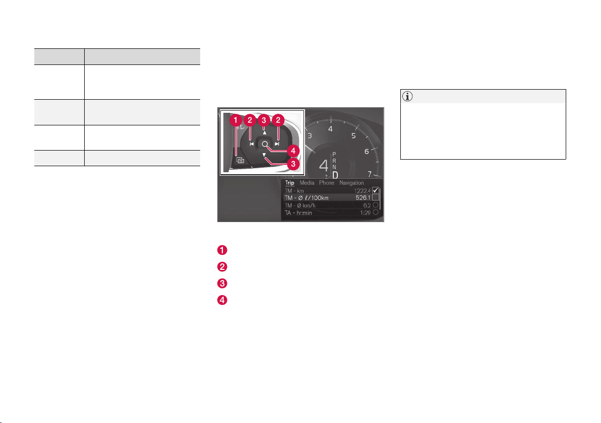
DISPLAYS AND VOICE CONTROL
App Functions
Trip computer
Media
player
Phone Calling a contact from the call
Navigation Guide to destination, etc.
Selection of trip meter, selection of what to show in the
driver display, etc.
Selection of active source for
the media player.
list.
Related information
Driver display (p. 77)
•
Overview of centre display (p. 102)
•
Handling the application menu in the driver
•
display (p. 97)
Handling the application menu in the driver display
The application menu (the app menu) in the
driver display is operated with the steering
wheel's right-hand keypad.
The app menu and the steering wheel's right-hand keypad.
Open/close
Left/right
Up/down
Confirm
Opening/closing the app menu
Press on open/close (1).
–
> The app menu opens/closes.
NOTE
It is not possible to open the app menu while
there is an unacknowledged message in the
driver display. The message has to be confirmed first before the app menu can be
opened.
The app menu closes automatically after a period
of inactivity or after certain options have been
selected.
Navigating and selecting in the app menu
1. Navigate between the apps by pressing on
the left or right (2).
> Functions for previous/next app are
shown in the app menu.
2. Browse through the functions for the
selected app by tapping on up or down (3).
3. Confirm or highlight an option for the function by pressing on confirm (4).
> The function is activated and for some
options the app menu then closes.
If the app menu is opened again, the functions of
the most recently selected app are shown first.
}}
97
Page 100
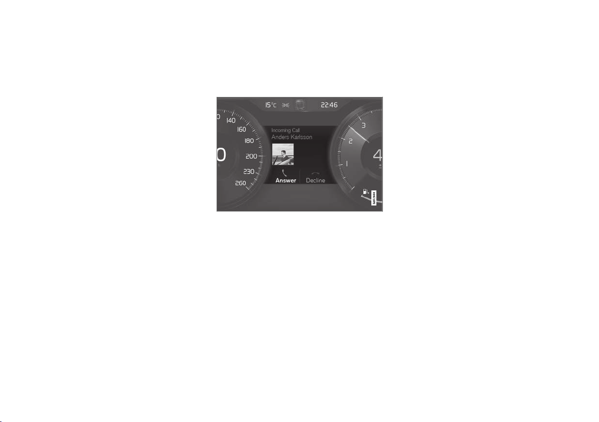
DISPLAYS AND VOICE CONTROL
||
Related information
Application menu in driver display (p. 96)
•
Messages in the driver display (p. 98)
•
Messages in the driver display
The driver display can show messages to inform
or assist the driver in the event of different
events.
Examples of messages in the driver display.
The driver display shows messages that are of
high priority for the driver.
Messages can be shown in different parts of the
driver display depending on what other information is currently being displayed. After a while, or
when the message has been acknowledged/
action taken if required, the message disappears
from the driver display. If a message needs to be
saved, it is placed in the
is opened from the app view in the centre display.
Message composition may vary and they can be
shown together with graphics, symbols or buttons
Car Status app, which
for acknowledging the message or accepting a
request, for example.
98
 Loading...