

Volvo Trucks North America, Inc.
Greensboro, NC USA
This Service Bulletin replaces Service Bulletin 371–44,
“Data Links, Fault Tracing” (11.2002), publication number
PV776–TSP177224.
Data Links, Fault Tracing
Service Bulletin
Trucks
Date Group No. Page
12.2004 371 44 1(25)
Data links, fault tracing
VN, VHD VERSION2
From build date 11.2002
T3015830
Contents
“Data Links, Fault Tracing” page 3
“Terminating Resistor, Checking” page 13
“J1708 Information Link, Fault Tracing” page 14
“J1939 Control Link, Fault Tracing” page 16
PV776-20020644 USA16430
Volvo Trucks North America, Inc. Date Group No. Page
Service Bulletin 12.2004 371 44 2(25)
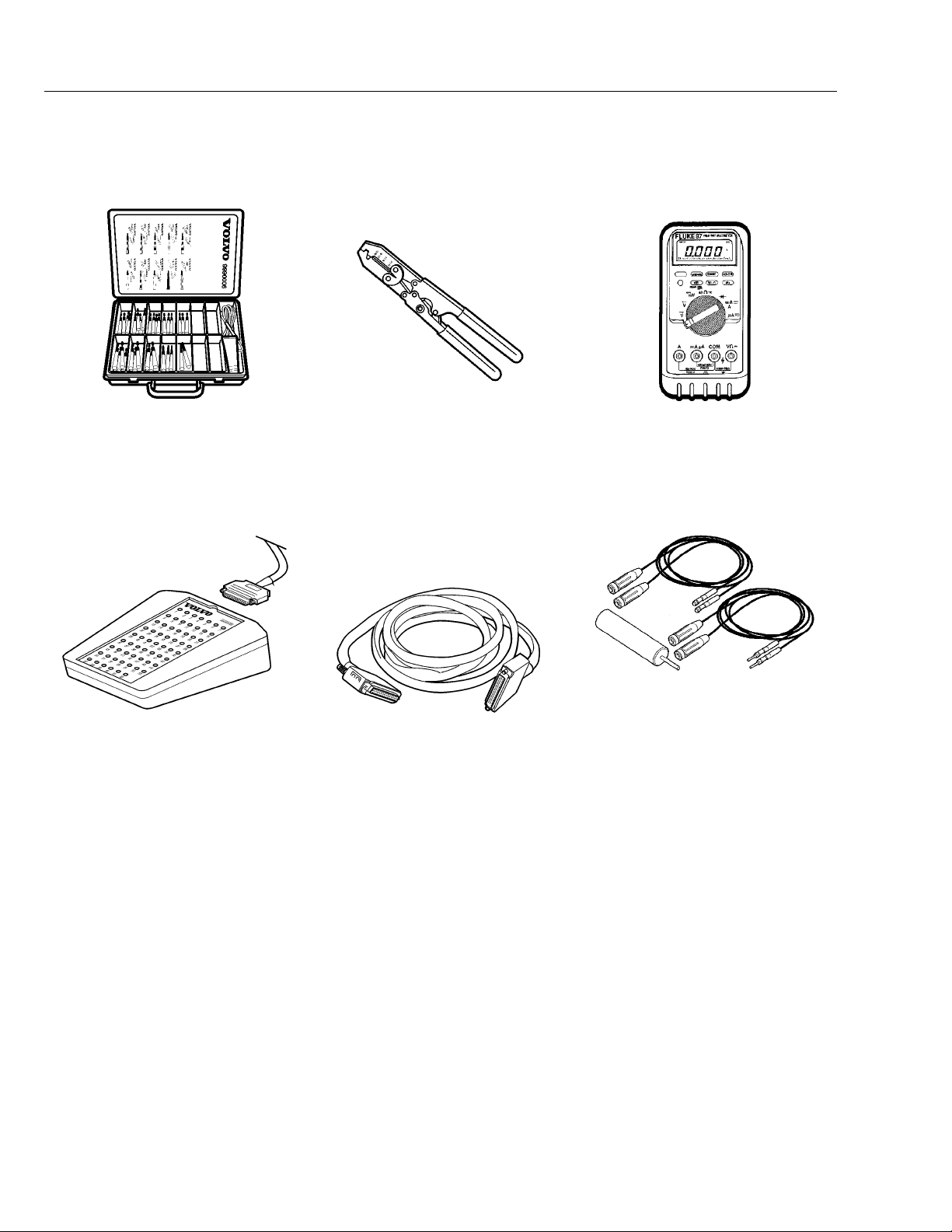
Tools
Special Tools
9990008
Set of Test Pins
9998699
Breakout Box 62 Pin
J-38125-8
Wire Crimpers
9990062
Cable Extension
J-39200
Digital Multimeter (DMM)
J-42449
JAE Terminal Probes

Volvo Trucks North America, Inc. Date Group No. Page
Service Bulletin 12.2004 371 44 3(25)
Troubleshooting
Data Links, Fault Tracing
General Troubleshooting Procedures
The control units share information via two different data links “information link SAE
J1587/1708” and “control link SAE J1939”
The messages on the SAE J1587/1708 information link are for example, fault codes and
warning messages. In some cases the SAE J1587/1708 link also acts as a reserve for
SAE J1939. VCADS Pro only communicates on SAE J1587/1708.
SAE J1939 is a faster link which means more data can be transmitted. SAE J1939
is used to transmit data that the system uses for control functions, for example,
engine speed (rpm).
Checks:
“J1708 Information Link, Fault Tracing” page 14
•
“J1939 Control Link, Fault Tracing” page 16
•
Use Multimeter J-39200 (or equivalent tool) to perform
•
tests.
When troubleshooting wiring and connectors use
•
breakout boxes/harnesses when available. A list
of various breakout boxes/harnesses is included in
“Special Tools” page 2.
Never pierce the wiring insulation with test probes.
•
Do not pierce through seals on water-resistant
•
connectors.
Never insert test probes into connectors. The probes
•
may spread the terminals and cause intermittent faults.
If breakout boxes/harnesses are not available, contact
•
the metal outer edges of connector terminals as
necessary to take readings.
Consult “VN or VHD Series Electrical Schematics” in
•
Group 37 for vehicle specific wiring and connector
information. These schematics include pin-out and
vehicle location drawings for connectors.

Volvo Trucks North America, Inc. Date Group No. Page
Service Bulletin 12.2004 371 44 4(25)
Visual Inspection
Before beginning electrical checks, visually inspect the
wiring and connectors.
Inspect for corrosion in wiring or connectors.
•
Check that terminal pins are not bent or damaged, and
•
are locked into their connectors and properly crimped.
Check that the terminal pins make good mechanical
•
contact with their mating pin.
To help locate intermittent faults, wiggle the wire and
•
connector while testing.
Wiring and Connectors
Troubleshooting data link wiring is no different than
troubleshooting any other wiring. A DMM is used to take
measurements for resistance or voltage at various points
in the circuit. Based on those readings and working with
wiring schematics, the technician can narrow the search
area until theexactcause of a wiring failure is determined.
For general information about how to troubleshoot the
wiring and connectors see "Troubleshooting Wiring and
Connectors" found in the "Electrical General, VN and
VHD" manual in group 30.
Volvo Trucks North America, Inc. Date Group No. Page
Service Bulletin 12.2004 371 44 5(25)
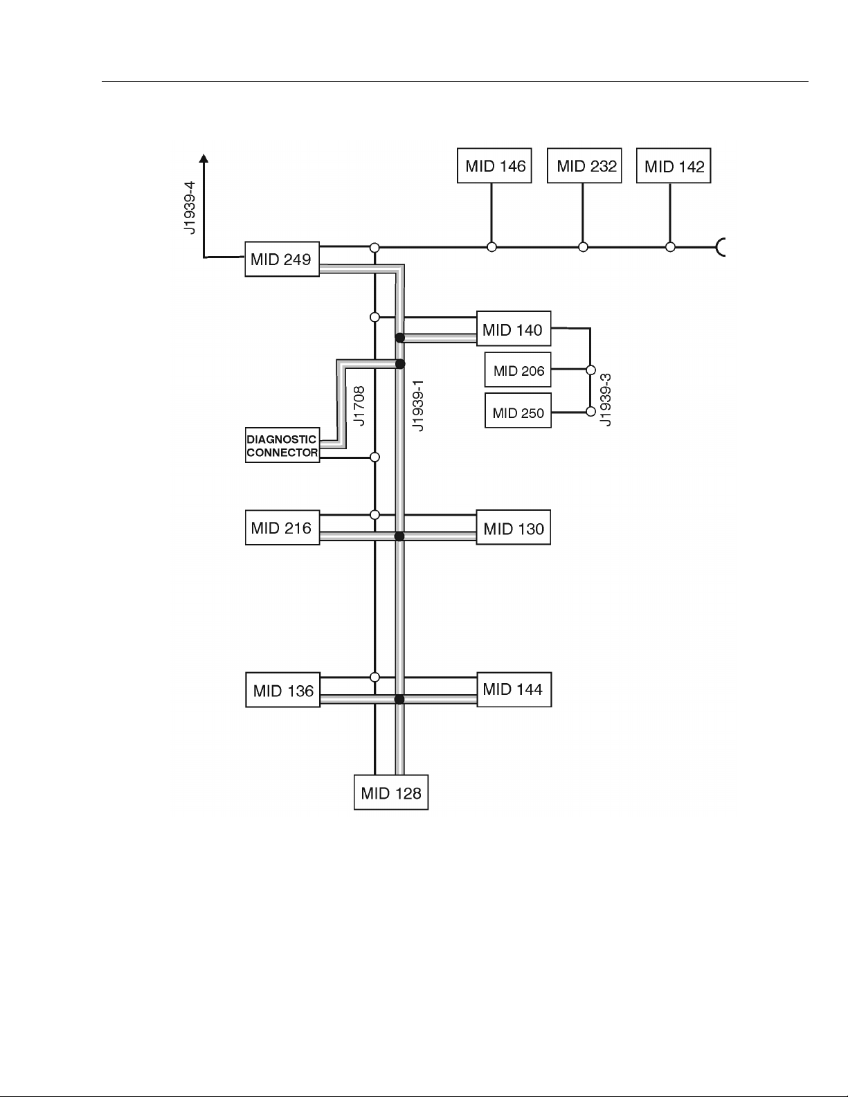
Data links
Note: Not all modules will be present
in every vehicle.
MID 128 Engine ECU
MID 136 Anti-lock Brake (ABS)
ECU
MID 140 Instrument Cluster
MID 142 Satellite
Communications
MID 144 Vehicle ECU
MID 146 Climate control ECU
MID 206 Radio
MID 216 Lighting Control
Module
MID 232 Airbag, control unit
MID 249 Body builder module
MID 250 Steering Wheel
Module
W3005654
J1939–1 Main network SAE
J1939
J1939–3 Section ofSAE J1939
under the instrument
cluster
J1939–4 Section ofSAE J1939
under the bodybuilder
control unit

Volvo Trucks North America, Inc. Date Group No. Page
Service Bulletin 12.2004 371 44 6(25)
SAE J1587/1708
For checking see “J1708 Information Link, Fault Tracing” page 14.
SAE J1587/1708 is used for, amongst other things, transmitting fault code information.
Faults which can affect the entire SAE J1587/1708 datalink can create problems when
fault tracing, since it can be difficult to communicate with the source in order to carry out
tests using VCADS pro. A simple way of checking if VCADS pro is in contact with all
control units on the SAE J1587/1708 link is “17034-2 Vehicle information, test”. An
indication that there is a problem with SAE J1587/1708 can be that fault codes from a
certain control unit can not be corrected.
There are various types of errors that store fault codes for the SAE J1587/1708 link
(SID 250). If a control unit is able to store a fault code then the faultmore than likely is
associated with faulty wiring, connectors or sensors. The fault could be an open-circuit
or short-circuit in the cable harness in one or more places. In order to determine an
open-circuit in the cable harness, check the voltage levels at each control unit. See
“J1708 Information Link, Fault Tracing” page 14.
Fault codes in the SAE J1587/1708 link (SID 250) can also be caused by another control
unit not transmitting information. The reason for this can be due to faults in components
connected to the other control unit. Therefore, all other fault codes must be corrected
before starting the datalink fault tracing process.
List of MID numbers
Note: Not all MIDs will be present on every vehicle.
MID 128 Engine ECU
MID 130 Transmission control unit
MID 136 Anti-lock Brake (ABS) ECU
MID 140 Instrument Cluster
MID 142 Satellite Communications
MID 144 Vehicle ECU
MID 146 Climate control ECU
MID 172 Test tool, ie. VCADS PRO
MID 206 Radio
MID 216 Lighting Control Module
MID 219 VORAD/ACC
MID 232 Airbag, control unit
MID 249 Body builder module (BBM)
MID 250 Steering Wheel Module

Volvo Trucks North America, Inc. Date Group No. Page
Service Bulletin 12.2004 371 44 7(25)
SAE J1939
For checking see “J1939 Control Link, Fault Tracing” page 16.
The information on the SAE J1939 control link is used for control functions. Therefore,
the diagnostics for SAE J1939 have been developed and supplemented with more fault
codes for a more precise reading. The fault codes that are transmitted on the SAE
J1587/1708 link are also transmitted, in the event of more serious faults, on the SAE
J1939 link.
If control unit A is missing the message from another control unit B, the fault codes
PSID 200 - 214 are used to determine from which control unit the message is missing.
If control unit B loses contact with the link, other control units can store fault codes
indicating control unit B has lost communications.
Example:
If there is an open - circuit on the SAE J1939 link at the vehicle ECU (MID 144), PC
connector, the message from the vehicleECU does not reach the other control units on
SAE J1939. The instrument cluster and ABS ECU use the messages from the vehicle
ECU. The instrument cluster and ABS ECU store fault codes when the message is not
received. The instrument cluster stores fault codes “MID 140 PSID 201 FMI 9” and the
ABS ECU stores “MID 136 PSID 201 FMI 9”.
PSID 201 is stored by both the instrument cluster and ABS ECU which indicates that the
vehicle control has an interruption in the SAE J-1939 data link. This can be useful in
order to find faults on the data link. If there is a fault in the cable harness the fact that
there is still contact between certain control units can be used to eliminate sections
of the cable harness. In the event of certain errors in the SAE J1939 link the fault
codes are stored as a SID 231 message.
Note: It is important to remember which control units the vehicle is equipped with and
which fault codes are stored in each control unit.
Explanation of PSID 200-214
Note: Not all controlunits will be presenton every vehicle.
PSID 200 Open-circuit, bad data, data link, engine
control unit (MID 128)
PSID 201 Open-circuit, bad data, data link, vehicle
ECU (MID 144)
PSID 202 Open-circuit, data link, instrument
cluster (MID 140)
PSID 204 Open-circuit, data link, ABS ECU (MID
136)
PSID 210 Open-circuit, data link, Lighting Control
Module(LCM) (MID 216)
PSID 214 Open-circuit, data link, body builder
module (MID 249)
Volvo Trucks North America, Inc. Date Group No. Page
Service Bulletin 12.2004 371 44 8(25)
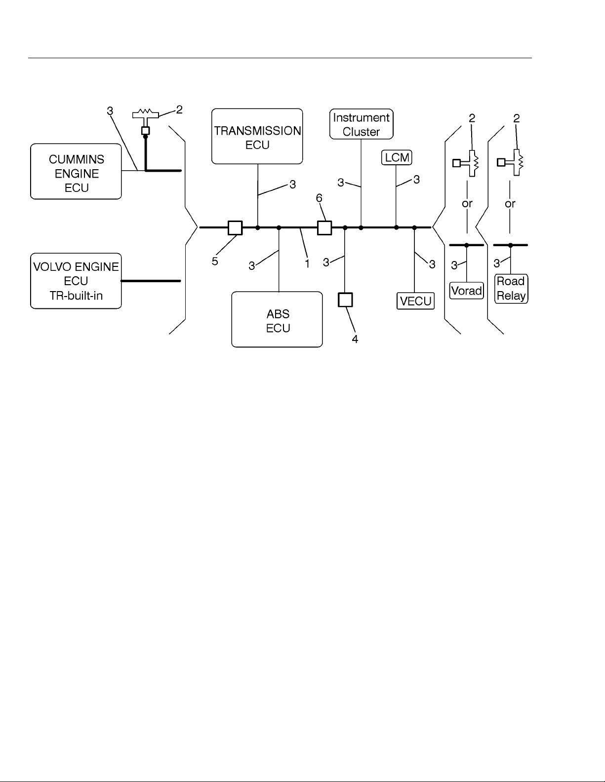
Data Link Construction
1 Data link backbone
2 Terminating resistors
3 Stub connections for ECUs
4 Diagnostic connector
The J1939 Control Data Link consistsof a backbone(1), terminating resistors(2) at each
end, and stubs spliced out (3) for each ECU on the data link. On vehicles with Volvo
engines, the terminating resistor at the engine end is located inside the Engine ECU.
The J1939 Control Data Link complies with SAE standards and consists of 2 twisted
wires:
Wire 406 is yellow in color and carries the Controller Area Network high (CAN_H)
•
digital signal of approximately 2–5 volts.
Wire 407 is green in color and carries the Controller Area Network low (CAN_L)
•
digital signal of approximately 0–3 volts.
5 Chassis harness — engine harness in-line connector
W3005333
6 Chassis harness — cab harness bulkhead pass-through
connector

Volvo Trucks North America, Inc. Date Group No. Page
Service Bulletin 12.2004 371 44 9(25)
Diagnostic Connector
9–pin Diagnostic Connector
Cavity
Position
A 0Z (B-)
B 402 (B+)
C 406C (CAN_H, yellow)
D 407C (CAN_L, green)
E not connected
F 400G (SAE A, 1708)
G 401G (SAE B, 1708)
H not connected
J 196DR (Ignition)
Note: The J1939 Data Link can be accessed at the 9–pin
diagnostic connector.
Circuit Description
W3005648

Volvo Trucks North America, Inc. Date Group No. Page
Service Bulletin 12.2004 371 44 10(25)
SID 231 J1939 Data Link Fault
W3005017
The following table lists Failure Mode Identifiers (FMI) that may be helpful in identifying
data link problems. Please note the following when troubleshooting data link failures
by fault codes.
The type of FMI that an individual ECU can monitor is dependent on the software in
•
the ECU. All FMIs cannot be recognized by all ECUs.
The ECU reporting the fault may not be the ECU that is involved at the site of the
•
specific failure. For example, The Engine ECU may report a data link fault that is
actually at the VECU. The VECU would not be able to report if the data link is broken
between the VECU and data link backbone.
FMI Description Note
0
1
2
3
4
5
6
7
8
9
10 Abnormal change rate
11
12
13
14
Data valid, but high
Date valid, but low
Data erratic A
Voltage shorted high
Voltage shorted low
Current low or open C
Current high or short C
Mech syst no response
Abnormal freq or PW
Abnormal update rate B
Failure unknown C
Loss of intelligent device D
Out of calibration
Special instruction
A. FMI 2, Data Erratic is given when the ECU does not see any J1939 messages
and is
not able
of a problem in the wiring, i.e., shorted high or low, or the ECU may be totally
disconnected from the J1939 data link. When an ECU detects this situation, it
should set the fault code FMI 2. Other ECUs will also set other fault codes for loss
of messages from this ECU.
B. FMI 9, Abnormal Update Rate is given when an ECU is seeing messages from
a specific ECU on the J1939 network, but needed data is not present. This is
typically where the J1939 data link is functioning, and the ECU is communicating, but
having a local problem with a sensor.
to communicate on the J1939 network. This is typically a result

Volvo Trucks North America, Inc. Date Group No. Page
Service Bulletin 12.2004 371 44 11(25)
C. FMI 11, Failure Unknown indicates an internal problem in the ECU.
D. FMI 12, Loss of Intelligent Device is given when an ECU is expecting to receive
messages from another ECU on the network, and the messages are not present. For
example, the Engine ECU expects certain messages from the ABS system; FMI 12 is
logged if those messages are not there. This fault is probably caused by a physical
break (open circuit) in the J1939 wiring, somewhere between the ECUs, or when an
ECU is off-line due to a blown fuse or bad component.
Note that the device that logs this fault is NOT the faulty ECU – it has instead
detected the fault.
J1939 Data Link Voltage Check
The J1939 Control Data Link operates at the following voltages:
Data Link Wires Key
Position
Wire 406 (CAN_H, yellow) On Pins for Wire 406 (yellow) - Ground Fluctuating
Wire 407 (CAN_L, green) On Pins for Wire 407 (green) - Ground Fluctuating
Between Wire 406 and Wire 407 On Pins for Wire 406 (yellow) - Pins for Wire
It is expected that the voltages quoted in the table above exist on Wire 406 (CAN_H,
yellow) and Wire 407 (CAN_L, green) at any point on the data link. Due to the fact that
multiple ECUs are both "talking" and "listening" any time the ignition key is on, the
voltage reading will have limited troubleshooting value.
Measuring Point Expected Value
between 2 - 5
Volts
between 0 - 3
Volts
Fluctuating
407 (green)
between 0 - 5
Volts

Volvo Trucks North America, Inc. Date Group No. Page
Service Bulletin 12.2004 371 44 12(25)
J1939 Data Link Resistance Check
When operating properly, the J1939 Control Data Link has a resistance of approximately
between Wire 406 (CAN_H, yellow) and Wire 407 (CAN_L, green) at any point on
60
the data link. Checks can be made at the diagnostic connector, terminating resistors, or
any ECU on the J1939 Control Data Link.
Use a DMM to check the resistance at suspected fault locations observing the following
points:
For detailed, vehicle specific schematics see "VN/VHD Electrical Schematics"
•
found in group 37.
Breakout boxes for some components may exist to aid in troubleshooting. See
•
"Tools" for more information.
Back probe connectors when possible to avoid pin or socket damage.
•
Terminating resistors must remain in the circuit for test.
•
Function Key
Position
Grounded Circuit
Check
Grounded Circuit
Check
J1939 Data Link
Resistance Check
Off Pins for Wire 406
Off Pins for Wire 407
Off Pins for Wire 406
Measuring Point Expected Value
OL (Infinite
(yellow) - Ground
(green) - Ground
(yellow) - Wire 407
(green)
Resistance)
OL (Infinite
Resistance)
60
If Expected ValueNot Correct Check:
Grounded Circuit
Grounded Circuit
1. Check terminating resistors. See
“Terminating Resistor, Checking” page
13.
2. Wiring/connector fault in backbone
or stubs. See “Wiring and Connectors”
page 4 and “J1939 Data Link
Troubleshooting Example” page 18.

Volvo Trucks North America, Inc. Date Group No. Page
Service Bulletin 12.2004 371 44 13(25)
Terminating Resistor, Checking
W3005518
Terminating Resistor, 2–pin
Terminating resistors are wired to each end of the J1939 data link to prevent signal
reflections. They must remain connected for the data link to function properly. The
resistance value of each terminating resistor is 120
data link, their combined resistance is 60
The terminating resistor at one end of the J1939 data link is located in the Fuse/Relay
Center near the VECU and the other near the engine ECU. On vehicles equipped
Volvo engines, the terminating resistor at the engine end is located inside the EECU.
On vehicles equipped with Cummins engine, the terminating resistor is located in the
harness area just outside of the Engine ECU.
since they are connected in parallel.
. When properly installed in the
A J1939 stub connection is located at the transmission area in the chassis harness.
On vehicles equipped with an electronically controlled transmission (Allison/Autoshift
II/Meritor Freedom Line), the connection to the transmission is located at the chassis
harness. On vehicles equipped with a manual non-electronically controlled transmission
- the connector stub will have an unterminated blanking plug installed.
Only two terminating resistors are used in a vehicle. Never install three in one truck.
If more than two terminating resistors exist in the J1939 circuit, damage to the ECU
electronics can occur over time. You can easily check to see if you have two resistors by
measuring the resistance between circuits 406 and 407, at the diagnostic connector,
with the ignition OFF. The correct resistance is 60
If by chance a vehicle has more terminating resistors installed in the link than required,
the resistance value between circuit 406 and 407 will be approx. 40 ohms. This would
give an indication to go and check the locations mentioned above and remove the plugs
one at a time until the correct resistance reading is obtained. You should then find that
you have more than one installed. To fix the problem order a blanking plug and install in
the appropriate location, depending on vehicle transmission type.
To check the terminating resistors, the J1939 data link can be accessed at the 9 pin
diagnostic connector.
Use a DMM to check the following:
9-pin Diagnostic Connector
Function Key Position Measuring Point Expected
Terminating
Resistor Check
Off Pin D - Pin C
.
Value
60
Note If Expected Value not met,
check
1. If 120 , one terminating
resistor missing or wiring fault.
2. If >1k
resistor missing or wiring fault.
3. If OL
4. If <1
wires.
, both terminating
(infinite), open circuit.
, short circuit in data link

Volvo Trucks North America, Inc. Date Group No. Page
Service Bulletin 12.2004 371 44 14(25)
3711-21-03-01
J1708 Information Link, Fault Tracing
Other special equipment: J-39200
NOTE!
During fault-tracing check the relevant connectors.
•
Check for loose connections, contact resistance
and oxidation. For a more detailed description of
fault-tracing cables and connectors, see separate
service information under group 37.
Do not use the chassis as a ground when taking
•
readings. Use the ground plate in the distribution box.
For measurement points and adapters see “Signal
•
Indication” for the relevant system.
Additional information
When checking the data link measurement and the
values are outside of the given ranges, there are several
possible explanations.
1
If the voltage is approx. greater than 5 V DC the data
link is possibly shorted to a higher voltage and must be
inspected to find the cause.
A wire of higher voltage could be cross connected
to the data link via chaffing or pin misalignment at
connectors or control units, etc.
A second, but least likely, possibility is that the internal
databus of an ecu has failed in some way causing
an interruption of messaging on the link. If this is
suspected, disconnect the suspect ecu temporarily or
either connect a spare ecu to check if the problem
goes away.
2
If the voltage is aprrox. less than 2 V DC the datalink
is possibly shorted to ground and must be inspected
to find the cause.
A wire of lower voltage or ground type could be
cross connected to the data link via chaffing or pin
misalignment at connectors or control units, etc.
Either one or both of the data link wires are shorted
to ground via a rub through (chaff). Inspect the
entire data link for possible signs of abrasion. Repair
according to guidelines outlined in this manual.
A third, but least likely, possibility is that the internal
databus of an ecu has failed in some way causing
an interruption of messaging on the link. If this is
suspected, disconnect the suspect ecu temporarily or
connect a spareecu to check if the problem goes away .

Volvo Trucks North America, Inc. Date Group No. Page
Service Bulletin 12.2004 371 44 15(25)
Checking sub-systems
1
Conditions:
Measurement box with adapter connected between
•
the relevant control unit and cable harness.
Measuring voltage using the multimeter with the
•
MAX
-function engaged.
Control unit connected.
•
The ignition key in the drive position.
•
Measuring points Desired value
SAE J1587/1708 A ground
SAE J1587/1708 B ground
SAE J1587/1708 A SAE J1587/1708 B
1
The voltage must vary within the interval.
Note: The voltage on the information link varies and
is dependent on the number of control units and traffic
on the information link.
J-39200
V ≈ 0-5VDC
V
≈ 5VDC
max
V
≈ 0VDC
min
V ≈ 0-5VDC
V
≈ 5VDC
max
V
≈ 0VDC
min
V ≈ 2-5VDC
1
1
MIN /

Volvo Trucks North America, Inc. Date Group No. Page
Service Bulletin 12.2004 371 44 16(25)
3711-21-03-02
J1939 Control Link, Fault Tracing
You must read and understand the precautions and
guidelines in Service Information, group 30, "General
Safety Practices", before performing this procedure.
If you are not properly trained and certified in this
procedure, ask your supervisor for training before
you perform it.
Other special equipment: J-39200
NOTE!
During fault-tracing check the relevant connectors.
•
Check for loose connections, contact resistance
and oxidation. For a more detailed description of
fault-tracing cables and connectors, see separate
service information under group 37.
Do not use the chassis as a ground when taking
•
readings. Use the ground plate in the distribution box.
For measurement points and adapters see “Signal
•
Indication” for the relevant system.
Checking sub-systems
1
Conditions:
Measurement box with adapter connected between
•
the relevant control unit and cable harness.
Control unit connected.
•
Measuring voltage using multi meter J-39200 with
•
the
MIN MAX
Ignition key in the drive position.
•
Note: The voltage of the control link varies and depends
on the number of control units and the traffic on the
control link.
Measuring points Desired value
SAE J1939A - ground V ≈ 2-5VDC
SAE J1939B - ground V ≈ 0-3VDC
SAE J1939A - SAE
J1939B
-function connected.
V ≈ 0-1VDC
J-39200

Volvo Trucks North America, Inc. Date Group No. Page
Service Bulletin 12.2004 371 44 17(25)
2
Conditions:
Measurement box with adapter connected between
•
the relevant control unit and cable harness.
Control unit connected.
•
Measuring resistance using a multimeter.
•
Ignition key in stop position.
•
Measuring points Desired value
SAE J1939A - SAE
J1939B
Two terminations
SAE J1939A - SAE
J1939B
One termination
Comments:
When the resistance R ≈ 60
probably fault free from the particular connector to
two terminating resistors.
If the resistance R ≈ 120
then measuring is only conducted to the terminating
resistor.
J-39200
R = 50 - 70
R = 100 - 140
the cable harness is
from the relevant connector

Volvo Trucks North America, Inc. Date Group No. Page
Service Bulletin 12.2004 371 44 18(25)
J1939 Data Link Troubleshooting Example
1 Data
W3005333
link
backbone
2 Terminating
resistors
3 Stub
connections
for
ECUs
4 Diagnostic
connector
5 Chassis
harness
—
Note: This example is intended as a guide for the
logic used to troubleshoot a data link wiring problem.
The illustration should be used to help clarify the
troubleshooting example. Always refer to vehicle-specific
wiring schematics found in Group 37 when performing
vehicle troubleshooting.
engine
harness
in-line
connector
6 Chassis
harness
—
cab
harness
bulkhead
passthrough
connector

Volvo Trucks North America, Inc. Date Group No. Page
Service Bulletin 12.2004 371 44 19(25)
1
Begin by visually verifying that the two terminating
resistors are in place:
1a. One at the engine ecu. Vehicle equipped with
the Volvo engine, the terminating resistor is built into
the EECU and is not visible. Vehicles with Cummins
engines the terminating resistor is located on the
engine harness.
1b. One inside the cab, forward of the fuse/relaypanel
(visible when the fuse/relay cover is removed).
2
Using an ohmmeter with the ignition key switch in the
OFF position, check the resistance between circuits 406
(CAN_H, J1939A, yellow) and 407 (CAN_L, J1939B,
green) at the diagnostic connector.
2a. If 60
that the backbone circuit is intact, since the 60
represents the two 120 terminating resistors in
parallel. If trouble is still present, it is most likely in
one of the ECU stub circuits or at the ECU terminal
themselves. Go to Step 6.
2b. If approximately 120
this indicates that one of the terminating resistors is
missing, poorly connected or else there is an open
circuit in the backbone at some point. Use the fault
codes (if present) to narrow down the likely location
based on which ECU’s are complaining about missing
data from other ECU’s. Go to Step 3.
2c. If approximately 40
there are more than 2 terminating resistors installed.
To fix the problem order a blanking plug and install
in the appropriate location, depending on vehicle
transmission type.
3
Disconnect the Cab-chassis/pass-through connector
(item 6) at the bulkhead and re-test the resistance of
circuit 406–407 at the diagnostic connector.
3a. If the resistance is the same as that measured in
Step 2b, then that means the trouble is likely on the
chassis side of the cab-chassis pass-through, since
the 120
located in the cab. Go to Step 4.
(±10 ) resistance is measured, it is likely
resistance is measured,
resistance is measured,
being measured must be teminating resistor
3b. If the resistance is greater than what was
measured in Step 2b, then the trouble is likely on the
cab side of the harness, since the different reading
means you can no longer ’see’ the engine side
terminating resistor. Go to Step 5.

Volvo Trucks North America, Inc. Date Group No. Page
Service Bulletin 12.2004 371 44 20(25)
4
With the pass-through (item 6) still disconnected, check
the resistance between circuit 406–407 on the chassis
harness side of the pass-through, ’looking’ towards the
engine (120
the harnesses to look for an intermittent connection,
check the following items:
Check for continuity between all circuit 406 points
•
— pass-though, EECU, terminating resistor, and
transmission (if automated/automatic transmission)
Check for continuity between all circuit 407 points
•
— pass-though, EECU, terminating resistor, and
transmission (if automated/automatic transmission)
The 406 and 407 backbone circuits can, also, be
disconnected at the engine-to-chassis harness in-line
connector (item 5 — located near the starter relay
breakout, near the bulkhead) to further isolatewhether the
problem exists on the ’engine’ side or the ’chassis’ side.
5
With the pass-through (item 6) still disconnected, check
the resistance between circuit 406–407 on the cab side of
the pass-through, ’looking’ into the cab (120
present). While shaking/moving the harnesses to look for
an intermittent connection, check the following items:
should be present). While shaking/moving
should be
Check for continuity between all circuit 406 points.
•
Check for continuity between all circuit 407 points.
•
6
Check for continuity between circuit 406 at the diagnostic
connector and all circuit 406 point at the ECU’s and
terminating resistors. All circuit 406 should have
continuity to all other ECU’s. Perform the same tests
for all circuit 407 points.
If continuity is not found at all points, the trouble
is most likely in the stub to that ECU, or the ECU
connector/terminal itself.

Volvo Trucks North America, Inc. Date Group No. Page
Service Bulletin 12.2004 371 44 21(25)
Service Procedures
3711-16-02-02
J1939 Data Link Wiring (Unshielded), Repair
You must read and understand the precautions and
guidelines in Service Information, group 30, "General
Safety Practices", before performing this procedure.
If you are not properly trained and certified in this
procedure, ask your supervisor for training before
you perform it.
Note: This procedure complies with TMC RP142
“High-Speed Data Link Repair Guidelines.”
Note: Stagger wire cuts and splices to minimize bulges in
data link cable.
W3004993
1 Cable bundle, existing
2 Cable bundle, new
3 Heat-shrinkable connector
1
Make certain the vehicles ignition is OFF before
beginning this procedure.
2
Remove the data link from the wiring harness as
necessary and cut out the damaged section of cable.
Note: The replacement section of cable (P
must be somewhat longer than the original to allow for
staggering of the splices.
3
Strip approximately 50 mm (2 in.) of cable jacket and
shield at each end of the splices to expose the wiring.
Use caution not to cut the wire insulation.
4
Slide a piece of heat-shrink tubing over each end of the
cut cablebundle to seal the data link after the wires have
been spliced. The tubing should be approximately 50 mm
(2 in.) longer than the repair area.
/N 982689)
1 Cable bundle, existing
2 Cable bundle, new
3 Heat-shrink tubing
W3004994

Volvo Trucks North America, Inc. Date Group No. Page
Service Bulletin 12.2004 371 44 22(25)
5
Stagger cut the wiring to minimize bulges in the data
link cable. Strip approximately 6.3 mm (0.25 in.) of
wiring insulation at each wire end. Use caution not
to cut the wire strands.
1 Cable bundle, existing
2 Cable bundle, new
1 Wire stop
W3004995
6
Observe polarity when connecting the 406 (CAN-H,
yellow) and 407 (CAN-L, green) wires. Use a heat
shrinkable wiring connector to splice the wires together.
Insert each end of the wire into the connector until it
hits the wire stop.
W3004996
W3004997
7
Insert the connector into the proper anvil on the crimping
tool and crimp. Gently tug on the spliced connection to be
sure the wire is secure.

Volvo Trucks North America, Inc. Date Group No. Page
Service Bulletin 12.2004 371 44 23(25)
8
Use a heat gun to activate the heat shrink. Look for
sealant at each end of the connector as evidence of a
good application. Note: Do not use an open flame to
apply heat shrink.
1 Visible sealant
1 Cable bundle, existing
2 Cable bundle, new
3 Heat shrink tubing
4 Visible sealant
W3004889
W3004883
9
Center the piece of heat shrinkable tubing installed in
step 5 over the entire splice area. There should be
approximately 25 mm (1 in.) overlap at each end of the
splice area. Starting at the center, use a heat gun to
shrink the tubing. Look for sealant at each end of the
connector as evidence of a good application. Note: Do
not use an open flame to apply heat shrink.
10
After both ends of the cable are spliced, install the data
link back into thewiring harness andsecure as necessary.

Volvo Trucks North America, Inc. Date Group No. Page
Service Bulletin 12.2004 371 44 24(25)
Wire Splice, Solder and Seal
You must read and understand the precautions and
guidelines in Service Information, group 30, "General
Safety Practices", before performing this procedure.
If you are not properly trained and certified in this
procedure, ask your supervisor for training before
you perform it.
W3000568
Fig. 1: Wire splicing
1 Strip as necessary
2 Wire
W3000569
1 Solder
2 Soldering iron
3 Heat shrink tubing with sealant
4 Wires twisted
Soldering Procedure
1
Clean and tin the soldering iron tip.
2
Clean the terminal to be soldered.
3
Strip the wire as necessary to fit the terminal. Do not cut
or nick the wire when stripping. Note: The replacement
section of cable (P
than the original to allow for staggering of the splices.
4
Slide a piece of sealant shrink tubing onto the wire.
/N 982689) must be somewhat longer
5
Insert the wire in the terminal and, with a pair of crimpers
(as recommended by the connector manufacturer),
squeeze the small tabs onto the wire insulation. Not all
types of terminals have these tabs. Be certain to use the
crimpers recommended by the connector manufacturer.
With a blunt instrument, form the bare wire so that it will
lay against the soldering area of the terminal.

Volvo Trucks North America, Inc. Date Group No. Page
Service Bulletin 12.2004 371 44 25(25)
6
Using the soldering iron, apply heat to the outside of the
terminal while holding the solder on the wire on the inside
of the terminal. When a sufficient amount of heat has
been transferred from the gun through the terminal and
into the wire, the solder will be melted by the wire. Melt a
sufficient amount of solder on the wire and withdraw
the solder and the tip of the iron.
NOTE: Do not hold the terminal with pliers or anything
metal during the solder operation, as heat will be
1 Solder
W3000571
2 Tabs (crimp over wire insulation)
3 Wire
4 Soldering iron
5 Terminal
conducted away from the terminal.
7
Slide the sealant shrink tubing over the soldered
connection, making sure all exposed wire is covered.
Heat the tubing with a heat gun to shrink. Shrink until the
tubing is tight around the wire and the sealant is visible
out of both ends of the tubing.
 Loading...