

Page 1

Service Manual
Trucks
Group 330–500
Starting and Charging
VN, VHD
PV776-TSP146025
Page 2

Page 3

Foreword
The descriptions and service procedures contained in this manual are based on designs and methods studies carried out up to March 2001.
The products are under continuous development. Vehicles and components produced
after the above date may therefore have different specifications and repair methods.
When this is believed to have a significant bearing on this manual, supplementary service bulletins will be issued to cover the changes.
The new edition of this manual will update the changes.
In service procedures where the title incorporates an operation number, this is a refer-
ence to an S.R.T. (Standard Repair Time).
Service procedures which do not include an operation number in the title are for gen-
eral information and no reference is made to an S.R.T.
The following levels of observations, cautions and warnings are used in this Service
Documentation:
Note: Indicates a procedure, practice, or condition that must be followed in order to
have the vehicle or component function in the manner intended.
Caution: Indicates an unsafe practice where damage to the product could occur.
Warning: Indicates an unsafe practice where personal injury or severe damage to the
product could occur.
Danger: Indicates an unsafe practice where serious personal injury or death could oc-
cur.
Volvo Trucks North America, Inc.
Greensboro, NC USA
Order number: PV776-TSP146025
© 2001 Volvo Trucks North America, Inc., Greensboro, NC USA
All rights reserved. No part of this publication may be reproduced, stored in
retrieval system, or transmitted in any forms by any means, electronic, mechanical, photocopying, recording or otherwise, without the prior written
permission of Volvo Trucks North America, Inc..
Page 4

Page 5

Contents
General .................................................................................................... 3
Starting and Charging ........................................................................... 3
Tools ........................................................................................................ 5
Special Tools ......................................................................................... 5
Design and Function ............................................................................. 9
Starting and Charging System Indicator Lights .................................... 9
Battery ................................................................................................... 9
Cold Cranking Amps ....................................................................... 10
Reserve Capacity ............................................................................ 10
Open Circuit Voltage ....................................................................... 10
Battery Locations .............................................................................. 10
Battery Cables ................................................................................... 11
Battery Disconnect Switch ................................................................ 11
Starting System ................................................................................... 12
Starting Circuit ................................................................................... 12
Starter ................................................................................................ 13
Preheat System ................................................................................... 13
Preheat Circuit ................................................................................... 13
Preheater Assembly .......................................................................... 14
Charging System ................................................................................. 15
Charging Circuit ................................................................................. 15
Alternator ........................................................................................... 16
Troubleshooting ................................................................................... 17
Battery Troubleshooting ....................................................................... 17
Battery State of Charge .................................................................... 18
Battery Surface Charge Removal ..................................................... 19
Load Testing Batteries ....................................................................... 20
Electronic Battery Testing .................................................................. 21
Starting System Troubleshooting ......................................................... 22
Troubleshooting Simplified Schematic, Starting System ................... 23
Troubleshooting Ignition Switch with VCADS Pro Tool ..................... 24
Troubleshooting Battery/Starter Cables With Digital Multimeter ....... 25
Troubleshooting Ignition Switch/Starter Relay Circuit With Digital
Multimeter .......................................................................................... 26
Troubleshooting Starter with Digital Multimeter ................................ 27
Preheat System Troubleshooting ........................................................ 28
Troubleshooting Preheater with VCADS Pro Tool ............................. 29
Troubleshooting Preheater with Fault Codes .................................... 29
Troubleshooting Simplified Schematic, D7 Preheater ....................... 30
Troubleshooting Simplified Schematic, D12 Preheater ..................... 31
Troubleshooting Preheater with Digital Multimeter ............................ 32
Charging System Troubleshooting ...................................................... 33
Troubleshooting Simplified Schematics, Charging System ............... 34
Troubleshooting Charging System with Digital Multimeter ................ 35
Troubleshooting Charging Indicator (Telltale) Lamp .......................... 37
Troubleshooting — Alternator Output Test with BVA-34 Tester ........ 38
Troubleshooting Starting and Charging System with The Accu-
racy Plus Tester ................................................................................. 39
Service Procedures ............................................................................. 41
Battery Cables, Removal and Installation ........................................... 41
All Cables .......................................................................................... 41
1
Page 6

Ground Cables .................................................................................. 42
Battery Jump Starting .......................................................................... 43
Battery, Replacement (One or Two) .................................................... 44
Battery Cables to Starter, Replacement ............................................. 45
Battery Inter-connection Cables, Replacement ................................... 47
Starter Motor, Replacement ................................................................ 49
Volvo D12B or D12C Engine ............................................................. 49
Starter Motor, Replacement ................................................................ 51
Volvo D7C Engine ............................................................................. 51
Starter Motor, Replacement ................................................................ 53
Cummins or Detroit Diesel Engine .................................................... 53
Preheater Fuse, Replacement ............................................................ 55
Preheater Relay, Replacement ............................................................ 56
Volvo D12B or D12C Engine ............................................................. 56
Preheater Relay, Replacement ............................................................ 58
D7C Engine ....................................................................................... 58
Preheater Element, Replacement ....................................................... 59
D12B or D12C Engine ...................................................................... 59
Preheater Element, Replacement ....................................................... 60
D7C Engine ....................................................................................... 60
Alternator, Replacement (Adjustable Mount) ...................................... 62
Alternator, Replacement (Fixed Mount) .............................................. 63
Feedback
Operation Numbers
2
Page 7

Group 33 Starting and Charging VN, VHD General
General
Starting and Charging
The starting and charging system on the VN/VHD series vehicles is comprised of batteries, the starter, alternator and
all the connecting wiring, cables and switches. Vehicles equipped with Volvo engines may also have preheaters installed in the intake manifold to assist starting. For maximum efficiency, all parts of the system must function properly.
Note: The information in this manual pertains specifically to the Volvo VN/VHD series vehicles.
For more general information on the starting and charging system, including test, refer to:
Vendor
Information
Delco Remy DRA/DP1029
Diagnostic Procedures For Heavy Duty Electrical Systems
Starting and Charging Circuit, Simplified Schematic.
This simplified schematic should only be used to clarify the design features of the VN/VHD starting and charging circuit. For detailed vehicle-specific schematics, refer to:
Service
Manual
IMPACT Function Group: 370
Electrical Schematics VN, VHD
Information Type: Schematics
W3004734
3
Page 8

4
Page 9
Group 33 Starting and Charging VN, VHD Tools
Tools
Special Tools
The tools referenced in this manual are listed below. They can be obtained by contacting your local Volvo Trucks parts
dealer, Kent-Moore at 1–800–328–6657, or you may call a local listed tool vendor.
Note: For VCADS Pro tooling refer to:
Service
Manual
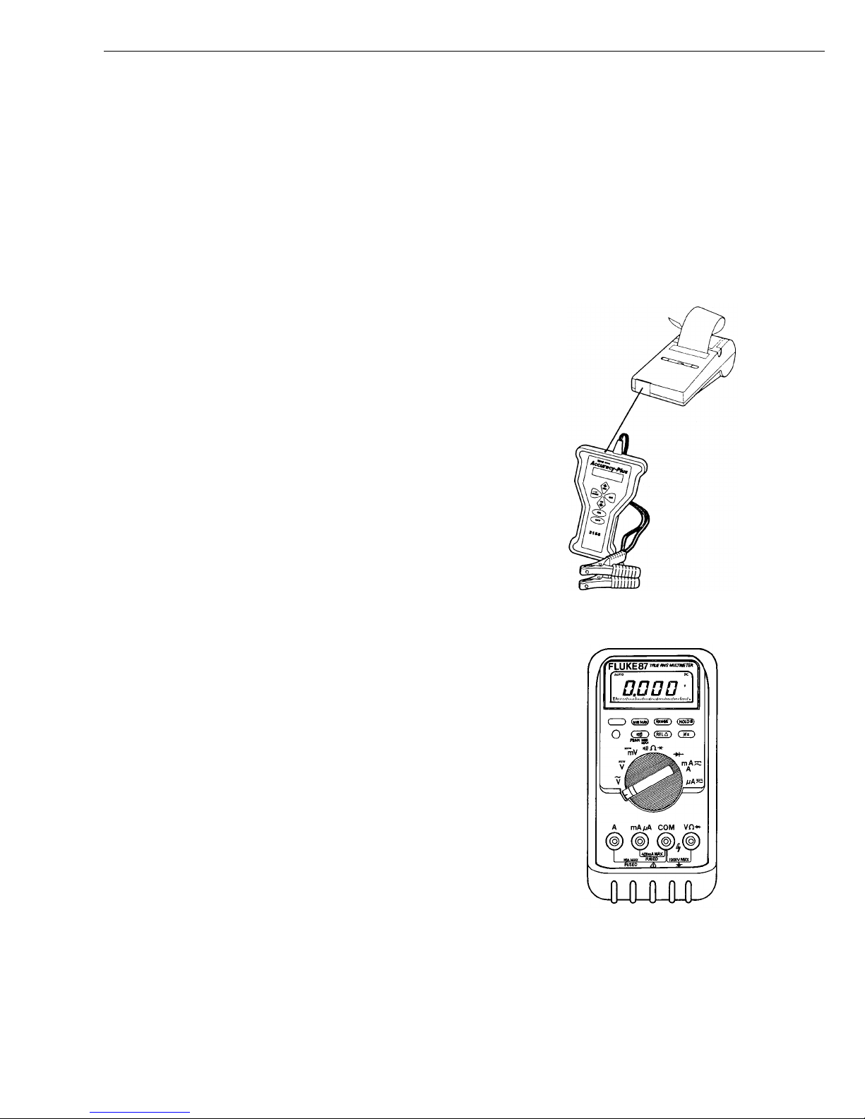
Battery tester kit. Includes: Tester J-44700 and Printer
238598, available from Kent-Moore (telephone: 800–
328–6657).
J-44701
VCADS Pro User’s Manual
Group Number 030–600
Fluke 87 digital multimeter, available from Volvo or KentMoore (telephone: 800–328–6657).
J-39200
W0001836
W2001014
5
Page 10

Group 33 Starting and Charging VN, VHD Tools
Relay puller tool, available from Kent-Moore (telephone:
800–328–6657).
J-43244
W0001917
VCADS Pro
For VCADS Pro tooling refer to:
Service
Manual
VCADS Pro User’s Manual
Group Number 030–600
Fan Belt Tensioner Tool, available from Volvo or KentMoore (telephone: 800–328–6657).
J-44392
W0001632
W0001817
(BT-33–73F) Belt Tension Gauge, available from KentMoore (telephone: 800–328–6657).
J-23600–B
6
W0001844
Page 11

Group 33 Starting and Charging VN, VHD Tools
BVA-34 System Analyzer
The BVA-34 System Analyzer is a digital, carbon pile,
battery load tester and starting/charging system analyzer. It is portable and designed for use in the heavy
truck market. Optional tester stand, part number ES-2, is
also available . For more information contact Auto-
®
Meter
at www.autometer.com.
(telephone: 435–283–4142) or visit their web site
W3004737
7
Page 12

8
Page 13

Group 33 Starting and Charging VN, VHD Design and Function
Design and Function
Starting and Charging System Indicator Lights
When the ignition key is turned “ON,” the Charging Indicator (telltale) lamp (1) will momentarily illuminate for a
bulb test. The lamp will remain on until the engine is
started. With the engine running and the alternator properly charging, the Charging telltale light should go off.
The instrument cluster left module is equipped with a
graphics display (2) that includes a voltmeter function.
With the voltmeter function active, the display will show a
battery icon and display the battery/charging voltage.
W3004552
If the battery/charging voltage exceeds 17 volts, the yellow “INFO” lamp (3) will illuminate and the graphic
display will show the voltage reading with the text message “TOO HIGH.”
T3008832
TOO HIGH
17.9 V
Battery
The battery is an electrochemical device for converting
chemical energy into electrical energy. The battery, or
battery pack, performs four basic functions:
1 It supplies energy for starting the engine.
2 It supplies energy to operate all the vehicles electri-
cal systems and accessories.
3 It acts as a voltage stabilizer for the electrical sys-
tem.
4 It supplies additional energy to operate the electrical
system during peak demands, for instance, when
the alternator is already at maximum output.
The battery case (1) is made of a strong, lightweight material, commonly polypropylene, to withstand shock and
vibration. The cover is vented to allow chemical gases to
escape. Each battery cell (2) is constructed of positive
and negative plates (3) that are insulated from each
other by a porous separator (4). Plate straps (5) connect
the positive and negative plates and provide a means of
interconnecting the cells. The cell is immersed in an
electrolyte solution of sulfuric acid and water. The electrical energy is produced in the battery by the chemical
reaction of the active materials that comprise the positive
and negative plates and the electrolyte. Each cell will
produce approximately 2.1 volts. The six cells that comprise the battery are connected in series to deliver
approximately 12.6 volts at the battery post (6).
W3004553
9
Page 14
Group 33 Starting and Charging VN, VHD Design and Function
Cold Cranking Amps
The “Cold Cranking Amps” rating is the amount of amperage load that can be maintained at –18
without the post voltage falling below 7.2 volts. This
rating is useful in determining the battery’s ability to
start an engine in cold weather conditions. The cold
cranking amp rating is determined by the amount of
plate surface area in each cell.
C(0
F)
Reserve Capacity
The “Reserve Capacity” is the number of minutes that
a battery can sustain a 25 Amp load at 27
until the post voltage drops to 10.5 volts. This rating is
useful in determining the battery’s ability to supply
operating power in the event of a vehicle charging system failure. The reserve capacity is determined by the
amount of active plate material in each cell.
C (80
F)
Open Circuit Voltage
The “Open Circuit Voltage” is the voltage at the battery
post with no loads applied.
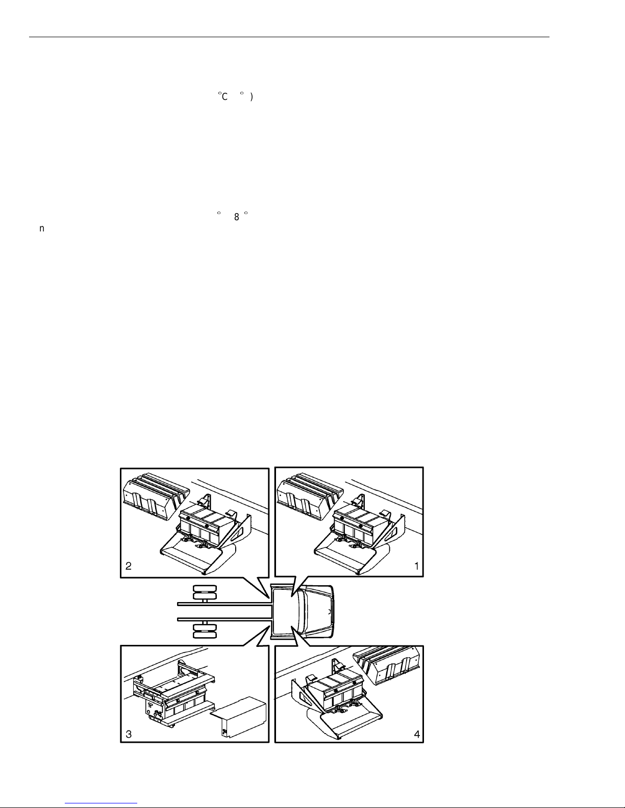
Battery Locations
Battery box locations vary per application. The standard mounting location (1) is on the left frame rail
under the cab steps. This is the mounting location for
all VN and some VHD vehicles. Depending on the
equipment ordered, there are three optional battery
box mounting locations for the VHD vehicle. See illustration for locations: (2), (3) and (4).
10
W3004555
Page 15
Group 33 Starting and Charging VN, VHD Design and Function
Battery Cables
All copper, 3/0 battery cables (1) are used on VN/VHD
vehicles. Single cables are used if the batteries are
mounted in the standard location. If the batteries are
mounted in optional locations, dual cables are used to
prevent excessive voltage drop due to cable length. Battery inter-connection cables (2) are 2/0 size. Some
applications may use interconnection bars instead of cables. All battery cables are sealed with polyvinyl chloride
(PVC) insulation to resist abrasion and the elements.
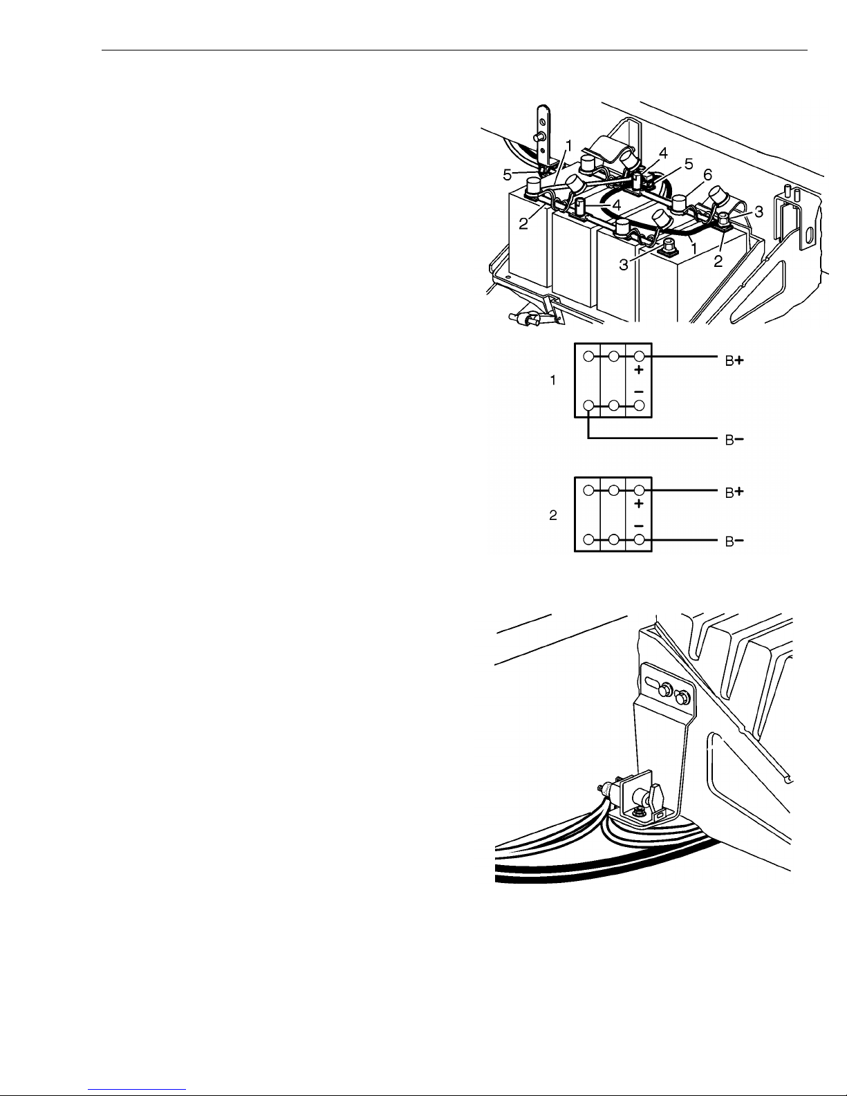
The battery cable terminals are secured to the batteries
with either stainless steel terminal nuts (3) or brass
jumper studs (4). Some applications may be equipped
with insulated terminal nuts that are made of plastic with
a brass insert. Protective covers (6) are installed on all
uninsulated battery cable terminal nuts/studs. Mounting
brackets (5) support and secure the battery cables at approximately 300 mm (12 in.) to 600 mm (24 in.) intervals
to avoid damage from abrasion, vibration, heat and
strain.
Ideally, battery sets should be connected to the battery/starter cables in a diagonal pattern (1) rather than
both cables being connected to one battery at the end of
the set (2). The diagonal connection will help assure that
all batteries in the set are cycled at the same rate, extending service life.
W3004556
Battery Disconnect Switch
As an option, some vehicles may have a master battery
disconnect switch (main switch). The switch will be
mounted on or near the battery box in all applications.
The battery disconnect switch should not be used as a
substitute for removing battery cables to prevent damage
to the vehicle when welding.
W3004557
W3004404
11
Page 16

Group 33 Starting and Charging VN, VHD Design and Function
Starting System
Starting Circuit
When the ignition switch is turned to the “START” position, power to energize the starter relay coil is supplied
on wire number 284. The starter relay coil is grounded
through the overcrank protection switch (OCP) or a
shorting jumper.
The OCP switch is located inside the starter. This switch
is optional. Where the OCP switch is not used, a shorting jumper is used to complete the starter relay coil
ground circuit.
When the starter relay is energized, a connection is
made from the starter solenoid BATT terminal (wire
285A) to the starter solenoid SW terminal (wire 285).
When the solenoid pulls in, a connection is made internally in the solenoid, which connects the battery terminal
to the motor terminal, then the starter begins to crank
the engine.
For more details see schematic in “Starting and Charging” page 3.
W3004339
overcrank protection (OCP) input switch.
12
W3003757
Starter Relay.
Page 17
Group 33 Starting and Charging VN, VHD Design and Function
Starter
Volvo VN/VHD vehicles are equipped with Delco Remy42MT starters for most applications. If the vehicle is
equipped with a Volvo D7 engine, it will be equipped with
a Delco-Remy 37MT starter. These starters, sometimes
referred to as starting motors, have a shift lever and solenoid housing that is totally enclosed to protect them
from the elements. The nose housing can be rotated to
“clock” the solenoid to accommodate various engine
mounting locations. A positive engagement shift mechanism moves the pinion into mesh with the engine
flywheel ring gear prior to cranking to minimize gear
tooth damage. An optional overcrank protection (OCP)
switch protects the starter in adverse starting conditions,
such as cold weather starting or operator misuse. The
OCP switch is a temperature sensitive circuit breaker
that prevents overcrank heat damage by opening the
starter relay ground, then automatically resetting when
the starter has cooled sufficiently.
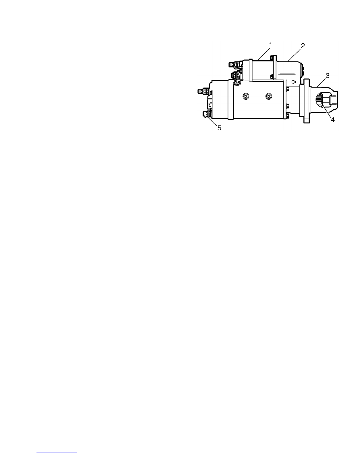
1 Solenoid
2 Shift Lever Housing
3 Nose Housing
4 Pinion
5 Overcrank Protection Input Switch
W3004558
Preheat System
Preheat Circuit
Vehicles equipped with Volvo engines may be equipped
with intake air preheaters to assist in cold weather starting.
Preheating is standard on the D7 engine with one preheat relay/element, and optional on the D12 engine with
two preheat relays/elements.
In normal operation, the ignition switch is turned to the
“preheat” position then released back to the “On”
position. The Vehicle Electronic Control Unit (VECU) recognizes the preheat request and sends the request to the
Engine Electronic Control Unit (EECU), via the J-1939
Control Data Link. The EECU will supply a ground to the
preheat relay(s), and the preheater will begin to operate.
Based on engine temperature, the EECU will time the interval for preheater operation. The operator may also
hold the ignition switch in the “preheat” position if additional preheat is desired after the timed preheat period.
The preheat relay(s) coil is supplied ignition power via a
fuse in the Truck Electrical Center (TEC) panel. The relay(s) is energized when a ground is supplied by the
EECU. When the relay(s) is energized, an internal connection is made that connects the preheater element
power supply from the alternator cable to the fuse that
connects to the preheat element(s). The preheat element(s) are case grounded.
page 3.
A “sense” circuit(s) provides information to the EECU to
confirm that the preheat circuit is intact. If the EECU determines that the circuit is not intact, a fault code(s) will
be generated.
For simplified schematic see: “Starting and Charging”
13
Page 18
Group 33 Starting and Charging VN, VHD Design and Function
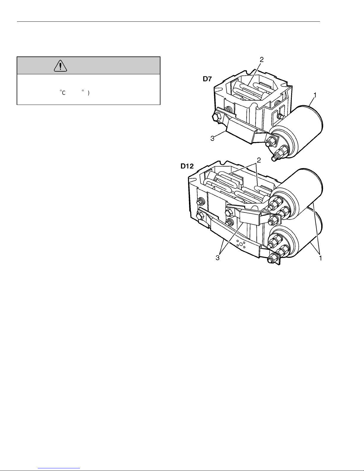
Preheater Assembly
WARNING
Use caution when working around the preheat
elements. When active, the elements will heat to approximately 705
the elements to cool to avoid severe burns.
The preheater assembly on a D7 engine is standard with
one relay element and fuse. The preheater assembly on
a D12 engine is optional with two relays, elements and
fuses.
C (1300F). Allow sufficient time for
1 Relay
2 Element
3 Fuse Assembly
W3004559
14
Page 19

Group 33 Starting and Charging VN, VHD Design and Function
Charging System
Charging Circuit
With the engine running, DC voltage is generated at the
alternator output (B+) terminal and supplied to the vehicles electrical system through wire no. 8. The alternator
is grounded by a wire from the ground terminal (B-) on
the alternator case to the engine ground terminal. A
fusible link in the ground circuit is designed to protect the
vehicle electrical system if a short in the alternator, alternator cable or battery cable occurs.
A wire from the alternator indicator light terminal to the
instrument cluster sends a signal to indicate that the
alternator is not charging. Vehicles with body builder applications may also have a wire from the alternator relay
terminal to provide engine speed information for PTO operation. Also see Starting and Charging Simplified
Schematic in “Starting and Charging” page 3.
W3004731
1 Output Terminal (B+)
2 Ground Terminal (B-)
3 Relay Terminal
4 Indicator Light Terminal
5 Ground Terminal (B-) 34SI only
15
Page 20

Group 33 Starting and Charging VN, VHD Design and Function
Alternator
The alternator converts the mechanical energy supplied
by the engine via drive belts into electrical energy that is
used to recharge the batteries and operate the electrical
devices on the vehicle. The alternator produces alternating current (AC), which is converted to direct current
(DC) by the diodes in the rectifier bridge. The rectifier
bridge also has design features to “clamp” voltage spikes
that may damage vehicle electronics. An internal voltage
regulator limits the charging voltage from 13.8 to 14.2
volts. Volvo VN/VHD vehicles currently are equipped with
one of three different Delco Remy alternators:
33SI — The 33SI alternator is a brushless design
•
for longer operating life. It is the standard alternator
used in most applications. It is available with 110
and 135 amp output ratings.
22SI — The 22SI alternator is a smaller, standard
•
brush type alternator. It is available with 100, 130
and 145 amp output ratings.
34SI — The 34SI alternator is internally identical to
•
the 33SI. The major difference is that the housing
has a fourth mounting lug to withstand higher vibration applications. The 34SI is currently only used in
VN vehicles equipped with Detroit Diesel engines.
16
W3004561
Page 21

Group 33 Starting and Charging VN, VHD Troubleshooting
Troubleshooting
Battery Troubleshooting
Before working on a vehicle, set the parking brakes,
place the transmission in neutral, and block the
wheels. Failure to do so can result in unexpected
vehicle movement and can cause serious personal injury or death.
WARNING
Always wear eye protection when working around batteries to prevent the risk of injury due to contact with
sulfuric acid or an explosion. (Important: If contacted
with sulfuric acid, flush immediately with water and
get medical attention).
WARNING
Batteries may contain explosive gases. To help minimize the risks of explosion, avoid sparks or open
flames near batteries. Do not smoke when servicing
batteries.
CAUTION
If there are other ground cables connected to the battery (such as engine ECU’s, satellite system, etc.),
disconnect those grounds first, then remove the main
battery ground cable. Electronic modules may be
damaged when additional grounds are connected/disconnected without the main battery ground
connected. Disconnect the main battery ground last.
CAUTION
In vehicles with a Supplemental Restraint System
(SRS), turn the ignition switch ON before connecting
the battery. Failure to do so may result in permanent
damage to the instrument cluster or other electronic
circuits within the vehicle. (This applies only to vehicles with SRS and a Cummins or Detroit Diesel
engine.) Always check for fault codes after repairs are
completed.
CAUTION
Possible damage to electronic components. Turn the
vehicle ignition switch OFF before disconnecting or
connecting any electronic components. Failure to
de-energize circuits may result in permanent damage
to electronic components.
17
Page 22
Group 33 Starting and Charging VN, VHD Troubleshooting
Battery State of Charge
The battery state of charge must be determined before
battery testing. Battery hydrometers that measured battery acid specific gravity were used to determine the
state of charge in earlier battery designs with removable
filler caps. In current “maintenance free” design batteries
the state of charge is determined by a built-in hydrometer or an open circuit voltage test.
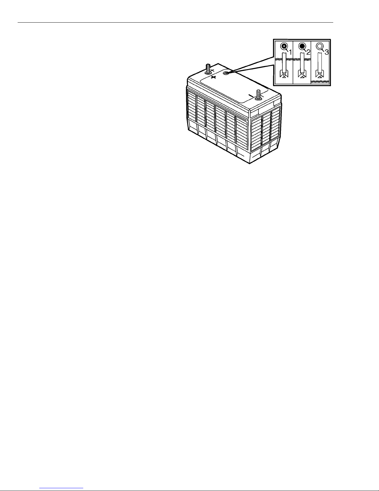
The battery may have a special temperature compensated hydrometer built into the cover to show at a glance
the battery’s state-of-charge. The hydrometer has a
green ball within a cage which is attached to a clear,
plastic rod. The green ball will float at a predetermined
specific gravity of the electrolyte that represents about
65% state-of-charge. When the green ball floats, it rises
within the cage and positions itself under the rod.
Visually a green dot then shows in the center of the hydrometer. The built-in hydrometer provides a guide for
battery testing and charging.
In testing, the green dot means the battery is charged
enough for testing. If the green dot is not visible, it
means the battery must be charged before the test procedure is performed.
1. State of charge 65% or above
2. Below 65% state of charge
3. Low electrolyte level
W3004562
In charging, the appearance of the green dot means that
the battery is sufficiently charged.
The hydrometer on some batteries may be clear or light
yellow. This means the fluid level is below the bottom of
the rod and attached cage. This may have been caused
by excessive or prolonged charging, a broken case, excessive tipping or normal battery wear out.
If a battery displays a clear eye, it must be replaced.
Do not attempt to charge, test or jump start the battery.
Note: The built-in hydrometer only monitors one battery
cell. Low state of charge in other cells will not be indicated by the built-in hydrometer.
The battery state of charge may also be checked by
reading the open circuit voltage. To check, connect a
voltmeter to the positive and negative battery post. If the
reading is below 12.40 volts, the battery is too low for
proper testing and must be recharged. If the reading is
above 12.66 volts, the surface charge must be removed
before testing. See: “Battery Surface Charge Removal”
page 19.
18
Page 23

Group 33 Starting and Charging VN, VHD Troubleshooting
Battery Surface Charge Removal
When a battery is charged, very small hydrogen gas
bubbles form on the surface of the battery plates, causing what is known as “surface charge.” When a voltmeter
is connected to the battery post, it may give a false reading if the surface charge is not removed.
Before testing a battery, the surface charge must be removed by one of the following methods:
Turn on the headlights for 2–3 minutes. Then allow
•
the battery to stabilize for 1 minute before testing.
Remove the Engine ECU fuse in the battery box to
•
prevent the engine from starting. Start the engine
for 5–10 seconds. Then allow the battery to stabilize
for 1 minute before testing.
Use BVA-34 System Analyzer or equivalent tool to
•
load the battery to 300 amps for 5–10 seconds.
Then allow the battery to stabilize for 1 minute before testing.
Note: The open circuit voltage must be at least 12.4
volts after the surface charge has been removed to continue battery testing.
19
Page 24
Group 33 Starting and Charging VN, VHD Troubleshooting
Load Testing Batteries
The BVA-34 System Analyzer is a digital, carbon pile,
battery load tester and starting/charging system analyzer. It is portable and designed for use in the heavy
truck market. The test that follows may be performed
with the BVA-34 System Analyzer, or equivalent carbon
pile type tester, and should be used as a general guide
for performing a battery load test. Read and follow the
test instructions supplied with the tester used to perform
battery testing.
1 Batteries must be tested individually. Remove
battery cables as described in “Battery Cables, Removal and Installation” page 41.
2 Visually inspect the battery for corroded terminals,
damage or a clear built-in hydrometer eye, if
equipped. Clean the terminals if needed. Replace
damaged batteries or batteries with clear hydrometer eyes (indicates electrolyte loss).
3 Screw the brass “jumper studs” onto the positive
and negative terminal before connecting the tester.
Do not connect the tester leads directly to the battery terminal post.
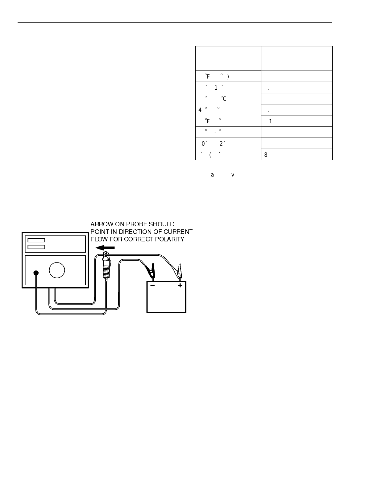
4
7
ESTIMATED
ELECTROLYTE
TERMPERATURE
70F (21C) and above 9.6
60F (16C) 9.5
50F (10C) 9.4
40F(4C) 9.3
30F (-1C) 9.1
20F (-7C) 8.9
10F (-12C) 8.7
0F (-18C) 8.5
Compare the voltage reading obtained to the temperature compensated chart above. If the battery
does not meet or exceed the minimum voltage required, replace the battery.
MINIMUM REQUIRED
VOLTAGE UNDER 15
SECOND LOAD
Connect the BVA-34 System Analyzer (or equivalent
tool) to the battery as shown. Set the voltmeter to
the “INTERNAL” setting. Zero the ammeter.
5 Check the battery open circuit voltage. The reading
must be between 12.40 and 12.66 volts to proceed.
If not, see “Battery State of Charge” page 18.
6 Adjust the load control knob to equal one half the
battery’s Cold Cranking Amp (CCA) rating. The battery CCA specification can be found on the battery
label. Maintain the load for 15 seconds then note
the battery voltage (with load applied).
20
W3004563
Page 25
Group 33 Starting and Charging VN, VHD Troubleshooting
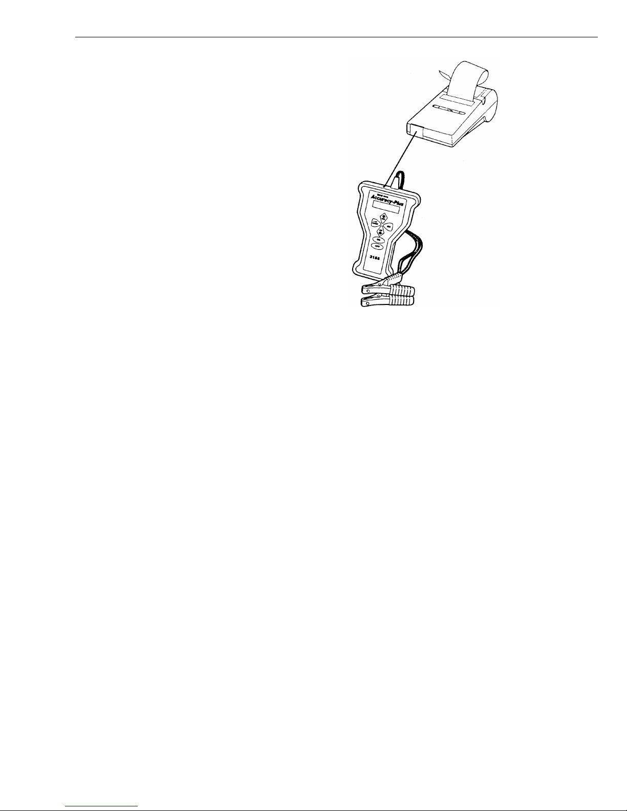
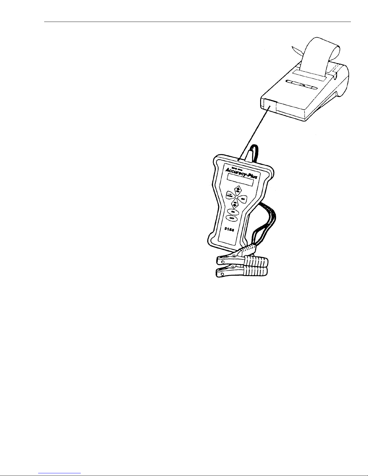
Electronic Battery Testing
The J-44700 Accuracy Plus HD Battery Tester is a hand
held electronic battery diagnostic tester. The tester applies variable loads to the battery and measures the
battery’s response. Results are then displayed and may
be printed if desired with the optional printer number
238598. Both the J-4477 Accuracy Plus tester and the
238598 printer are available in kit part number J-44701.
The test that follows may be performed with the J-44770
Accuracy Plus HD Battery Tester, or equivalent electronic testers, and should be used as a general guide for
performing electronic battery testing. Read and follow
the test instructions supplied with the electronic test
equipment used to perform battery testing.
1 Batteries must be tested individually. Remove
battery cables as described in “Battery Cables, Removal and Installation” page 41.
2 Visually inspect the battery for corroded terminals,
damage, or a clear built-in hydrometer eye if
equipped. Clean the terminals if needed. Replace
damaged batteries or batteries with clear hydrometer eyes (indicates electrolyte loss).
J-44700 Accuracy Plus HD Battery Tester.
W0001836
3 To operate the Accuracy Plus tester, connect the
positive and negative tester leads to the battery stud
posts. Select the “Battery Test” and follow the on
screen prompts until the test is complete. Test results will appear on screen.
21
Page 26
Group 33 Starting and Charging VN, VHD Troubleshooting
Starting System
Troubleshooting
Before working on a vehicle, set the parking brakes,
place the transmission in neutral, and block the
wheels. Failure to do so can result in unexpected
vehicle movement and can cause serious personal injury or death.
WARNING
Always wear eye protection when working around batteries to prevent the risk of injury due to contact with
sulfuric acid or an explosion. (Important: If contacted
with sulfuric acid, flush immediately with water and
get medical attention).
WARNING
WARNING
HOT ENGINE! Keep clear of all moving parts or hot
engine parts and/or fluids. A hot engine an/or fluids
can cause burns.
CAUTION
Possible damage to electronic components. Turn the
vehicle ignition switch OFF before disconnecting or
connecting any electronic components. Failure to
de-energize circuits may result in permanent damage
to electronic components.
CAUTION
Never use the ohmmeter mode of the DMM in a powered circuit, or as a substitute for a voltmeter or
ammeter, since this will result in damage to the instrument. Use the ohmmeter mode only when power is
removed from the circuit.
Batteries may contain explosive gases. To help minimize the risks of explosion, avoid sparks or open
flames near batteries. Do not smoke when servicing
batteries.
22
Page 27
Group 33 Starting and Charging VN, VHD Troubleshooting
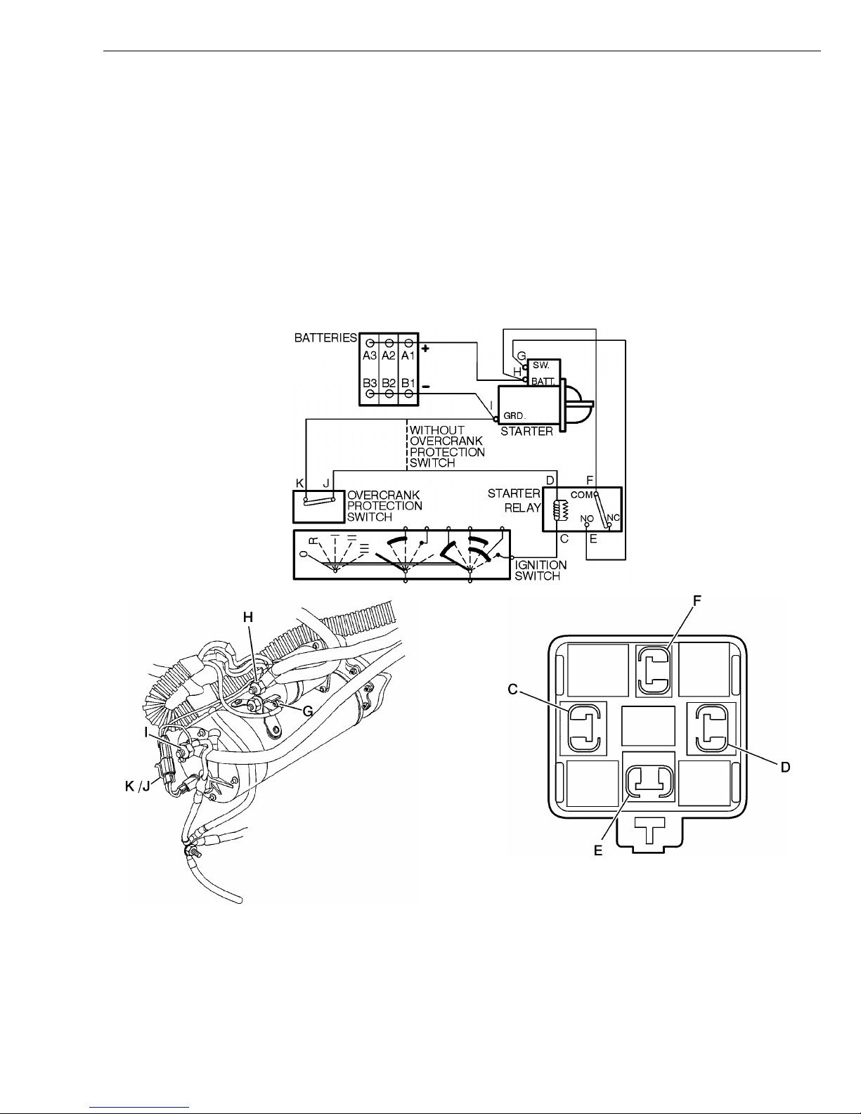
Troubleshooting Simplified
Schematic, Starting System
The simplified schematic and illustration below should be used to clarify the troubleshooting procedures in
“Troubleshooting Battery/Starter Cables With Digital Multimeter” page 25 , “Troubleshooting Ignition Switch/Starter
Relay Circuit With Digital Multimeter” page 26 and “Troubleshooting Starter with Digital Multimeter” page 27. For detailed, vehicle-specific schematics refer to:
Service
Manual
IMPACT Function Group: 370
Electrical Schematics VN, VHD
Information Type: Schematics
W3003745
Starter
Motor
H, I, J and K are measuring points. For details see
“Troubleshooting Battery/Starter Cables With Digital
Multimeter” page 25.
W3004564
W3003744
Starter
Relay
Switch
The connector is illustrated from the relay insertion side.
C=86 12V from Ignition Switch
D=85 Coil Ground
E=87 12V to Starter Solenoid
F=30 12V Supply
23
Page 28
Group 33 Starting and Charging VN, VHD Troubleshooting
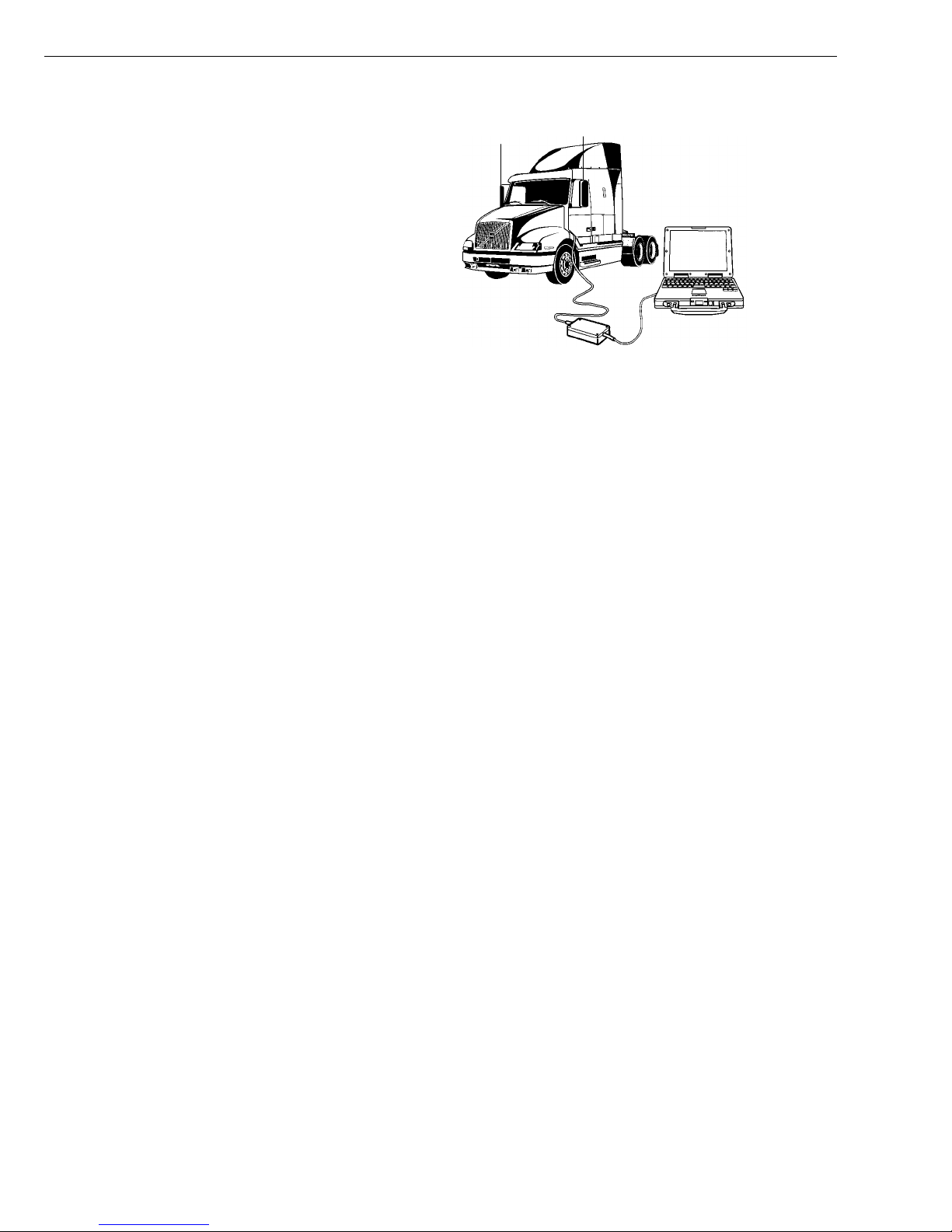
Troubleshooting Ignition Switch
with VCADS Pro Tool
The VCADS Pro Tool is a Windows 95 based PC tool
that can be used to perform some ignition switch testing.
The following is a brief description of tests that are currently available.
Test number 3340–08–02–01, “Ignition Switch, test”
Indicators on the VCADS Pro Screen will illuminate green
when the ignition key is turned to the “Start” position.
For detailed information about the VCADS Pro Tool op-
eration see refer to:
Service
Manual
VCADS Pro User’s Manual
Group Number 030–600
Note: This test only applies to vehicles with a Vehicle
ECU (Volvo engines).
W0001632
24
Page 29

Group 33 Starting and Charging VN, VHD Troubleshooting
Troubleshooting Battery/Starter
Cables With Digital Multimeter
The starter is supplied power and ground through cables
connected directly to the batteries. Excessive resistance
in the cables or connectors will cause decreased current
flow to the starter.
Due to the high current flow demands of the starting
circuit, voltage drop tests are more effective than ohmmeter tests in determining if excessive resistance exists
in the cable assemblies.
1 Check for 12.4V at the battery cable terminals (A1 &
B1) to the starter motor. If 12.4 V is not present or if
a weak battery(s) is suspected, see: “Battery Troubleshooting” page 17 for battery testing information.
2 Test complies with SAE J541 (10/96) or 0.1 volts
per 100 amps current draw. Specification assumes a
typical 700 amps starting current draw.
Function Key Position Measuring Point Approximate
Value
Positive
Cable
Start Battery positive-
post (A1)/Starter
"BATT" post (H)
<0.7 V drop. See
Note 2 above.
3 Confirm that the cables between batteries are clean,
tight and in proper working order.
4 Remove engine ECU fuses, located in the battery
box, to prevent the engine from running during the
tests.
Use the digital multimeter J-39200 or equivalent tool to
perform the test in the table below. The measuring
points referenced in the tables as A,B,C etc. correspond
to measuring points that are illustrated in the simplified
schematics and drawing. See: “Troubleshooting Simplified Schematic, Starting System” page 23.
Note: Due to battery mounting locations some vehicles
will have dual positive and negative cables. This test assumes that both cables are connected.
Note: Test complies with SAE J541 (10/96) of 0.1 volts
per 100 amp current draw. Specification assumes a
maximum of 700 amps starting current draw and normal
circuit temperature of 20
Note Possible Cause (if ex-
Starter cranking
engine
C (68
F).
pected value not correct)
Positive battery cable or
connectors
Negative
cable
Positive
InterConnect
Cables
Negative
InterConnect
Cables
Start Battery negative
post (B1)/Ground
post at starter (I)
Start Individual Battery
Positive Post
A1/A2; A2/A3;
etc.
Start Individual Battery
Negative Post
B1/B2;B2/B3;
etc.
<0.7 V drop. See
Note 2 above.
<0.1 V drop
between any terminals
<0.1 V drop
between any terminals
Starter cranking
engine
Starter cranking
engine
Starter cranking
engine
Negative battery cable or
connectors
Positive battery interconnect cable or connections
Negative battery interconnect cable or connections
25
Page 30

Group 33 Starting and Charging VN, VHD Troubleshooting
Troubleshooting Ignition
Switch/Starter Relay Circuit With
Digital Multimeter
When the “start” position is selected at the ignition
switch, 12 volts are supplied to the starter relay coil. If
the starter relay coil is properly grounded, either directly
or through the overcrank protection switch, the starter relay will energize and close the contacts between the
“common” and “normally open” terminals.
This creates a connection between the battery that connects to the “common” terminal, and the starter solenoid
switch feed, that connects to the “normally open” terminal. With this connection made, 12 volts are supplied to
the starter solenoid, which engages, and the starter motor begins to crank the engine.
The overcrank protection switch is designed to open and
prevent the starter from turning if the starter becomes
excessively hot. It should reset when the starter cools
sufficiently.
Function Key
Position
Measuring Point Expected
Value
1 Check for 12.4V at the battery cable terminals (A1 &
B1) to the starter motor. If 12.4 V is not present or if
a weak battery(s) is suspected, see: “Battery Troubleshooting” page 17 for battery testing information.
2 Confirm that the cables between batteries are clean,
tight and in proper working order.
3 Remove the engine ECU fuses located in the bat-
tery box to prevent the engine from running during
the tests.
4 Unplug the starter relay from the connector.
Use digital multimeter J-39200 or equivalent tool to per-
form the test in the table below. The measuring points
referenced in the tables as A,B,C, etc. correspond to
measuring points that are illustrated in the starting system simplified schematics and drawing. See
“Troubleshooting Simplified Schematic, Starting System”
page 23.
Note Possible Cause (if
expected value not correct)
Start signal to
starter relay
Ground to
starter relay
Battery signal
to starter relay
Start signal to
starter solenoid
Start Ignition switch ter-
minal at the starter
relay (C)/alternate
ground
Off Ground terminal
at starter relay
(D)/alternate
ground
Off Battery terminal at
starter relay
(F)/alternate
ground
Start SW terminal at
starter solenoid
(G)/alternate
ground
12V 1 Power supply to igni-
tion switch
2 Connectors/ wiring
fault in circuit from ignition switch to starter
relay
3 Ignition switch
<1
12V 1 Power supply to
12V Reinstall
relay to connector.
Starter relay
should
"click" when
energized.
1 Connectors/ wiring
fault in ground circuit
from starter relay
2 Overcrank protection
switch open (if
equipped)
starter "batt" post
2 Connectors/ wiring
fault in circuit from
starter "batt" post to
starter relay
1 Connectors or wiring
faults in starter relay/starter solenoid
circuit
2 If values in previous
test OK, probably
starter relay failure
Overcrank
Protection
(OCP) Switch
26
Off OCP Switch con-
nector (K/J)
<1
Not
equipped on
all engines
1 Starter overheated
2 OCP Switch failure
Page 31

Group 33 Starting and Charging VN, VHD Troubleshooting
Troubleshooting Starter with
Digital Multimeter
The starter motor/solenoid is supplied power and ground
through cables connected directly to the batteries. The
starter solenoid is engaged when a 12 volt signal is delivered to the “SW” terminal via the starter relay. When
the starter solenoid engages, a connection is made internally in the solenoid that connects the battery and
motor terminals and the starter cranks the engine.
1 Check for 12.4V at the battery cable terminals (A1 &
B1) to the starter motor. If 12.4 V is not present or if
a weak battery(s) is suspected, see: “Battery Troubleshooting” page 17 for battery testing information.
Function
Power supply
from batteries
Ground from
batteries
Key Position Measuring
Point
Off Starter "Batt"
post (H) / alternate
ground
Off Ground post
at starter (I) /
alternate
ground
Expected
Value
12V 1 Positive battery cable or con-
<1
2 Confirm that the cables between batteries are clean
tight and in proper working order.
3 Remove the engine ECU fuses located in the battery
box to prevent the engine from running during tests.
Use a digital multimeter J-39200 or equivalent tool to
perform the test in the table below. The measuring
points referenced in the tables as A, B, C etc. correspond to measuring points that are illustrated in the
starting system simplified schematics and drawing. See:
“Troubleshooting Simplified Schematic, Starting System”
page 23.
Note Possible Cause (if expected
value not correct)
nectors. See: “Troubleshooting
Battery/Starter Cables With
Digital Multimeter” page 25.
1 Negative battery cable or con-
nectors. See: “Troubleshooting
Battery/Starter Cables With
Digital Multimeter” page 25.
Start signal
from starter
relay.
If all the measurements are correct and the starter
•
will not engage, the starter is probably defective.
If all the measurements are correct and the starter
•
engages, but will not crank or the engine cranks
slowly, perform the following checks before replacing
starter:
Start Starter "SW"
terminal (G)
/alternate
ground
12V Starter
should
crank with
terminal energized
1 Check that the engine can be manually turned with
2 Check the starting system with the engine at operat-
3 Perform the test “Troubleshooting Battery/Starter
1 Starter relay.
2 Connectors or wiring faults in
starter relay/ignition switch circuit. See: “Troubleshooting
Ignition Switch/Starter Relay
Circuit With Digital Multimeter”
page 26.
a reasonable amount of effort to eliminate the possibility of a mechanical engine fault.
ing temperature. Extreme cold will make the engine
more difficult to turn and will reduce the batteries
output.
Cables With Digital Multimeter” page 25.
27
Page 32

Group 33 Starting and Charging VN, VHD Troubleshooting
Preheat System Troubleshooting
Before working on a vehicle, set the parking brakes,
place the transmission in neutral, and block the
wheels. Failure to do so can result in unexpected
vehicle movement and can cause serious personal injury or death.
CAUTION
Use caution when working around the preheat
elements. When active, the elements will heat to approximately 705
the elements to cool to to avoid severe burns.
C (1300
F). Allow sufficient time for
Possible damage to electronic components. Turn the
vehicle ignition switch OFF before disconnecting or
connecting any electronic components. Failure to
de-energize circuits may result in permanent damage
to electronic components.
Never use the ohmmeter mode of the DMM in a powered circuit, or as a substitute for a voltmeter or
ammeter, since damage to the instrument will result.
Use the ohmmeter mode only when power is removed
from the circuit.
CAUTION
CAUTION
CAUTION
Do not keep the ignition key in the preheating position
longer than approx. 15 seconds. Allow the starting
heater to cool between each activation or damage to
the preheater can occur.
28
Page 33

Group 33 Starting and Charging VN, VHD Troubleshooting
Troubleshooting Preheater with
VCADS Pro Tool
The VCADS Pro tool is a Windows 95 based PC tool
that can be used to perform some preheater testing. The
following is a brief description of tests that are currently
available.
Test number — 3330–08–02–01, preheat test.
Indicators on the VCADS Pro screen will illuminate
green when the ignition key is turned to the preheat position and when the preheat relay 1 and/or 2 is activated.
The VCADS Pro Tool also displays the engine coolant
temperature.
For detailed information about the VCADS Pro Tool operation, refer to:
Service
Manual
VCADS Pro User’s Manual
Troubleshooting Preheater with
Fault Codes
Check for stored fault codes when beginning troubleshooting procedures for preheating. If any of the
following fault codes is present, refer to:
Group Number 030–600
W0001632
Service
Information
IMPACT Function Group: 0
MID 128 — PID 45, preheating
•
MID 128 — SID 70, preheating element 1
•
MID 128 — SID 71, preheating element 2
•
Fault Tracing Information
Diagnostics Binder
Information Type: Diagnostics
29
Page 34

Group 33 Starting and Charging VN, VHD Troubleshooting
Troubleshooting Simplified
Schematic, D7 Preheater
The simplified schematic and lllustration below should clarify the procedures in “Troubleshooting Preheater with Digital
Multimeter” page 32. For detailed, vehicle-specific schematics refer to Function Group 370, Service Manual: Electrical
Schematics VN, VHD. Information Type: Schematics.
W3003776
Wire color codes in schematic:
SB Solid Black
BL/R Blue/Red
R Red
R/W Red/White
Y Yellow
GN Green
W3003778
A, B, C and D are measuring points. See:
“Troubleshooting Preheater with Digital Multimeter” page
32 for more information.
30
Page 35

Group 33 Starting and Charging VN, VHD Troubleshooting
Troubleshooting Simplified
Schematic, D12 Preheater
The simplified schematic and lllustration below should clarify the procedures in “Troubleshooting Preheater with Digital
Multimeter” page 32. For detailed, vehicle-specific schematics refer to Function Group 370, Service Manual: Electrical
Schematics VN, VHD. Information Type: Schematics.
Wire color codes in Schematic:
SB Solid Black
BL/R Blue/Red
R/W Red/White
Y Yellow
GN Green
W3003779
A, B, C and D are measuring points. See:
“Troubleshooting Preheater with Digital Multimeter” page
32 for more information. 1: Relay 1, 2: Relay 2.
W3003777
31
Page 36

Group 33 Starting and Charging VN, VHD Troubleshooting
Troubleshooting Preheater with
Digital Multimeter
Use digital Multimeter J-39200 or equivalent tool to perform the test in the table below. The measuring points referenced in the table as A, B, C, etc. correspond to measuring points that are illustrated in the preheat simplified
schematics and drawings in “Troubleshooting Simplified Schematic, D7 Preheater” page 30 and “Troubleshooting
Simplified Schematic, D12 Preheater” page 31.
These measuring points should not be confused with the wire color codes that are listed beside each schematic.
Each preheat relay, fuse and element must be checked independently on D12 engines.
Function Key
Position
Power Supply to
Relay Coil
Ground to Relay
Coil
Control Signal Preheat Control Wire (B) to al-
Relay Coil Function Test
Power Supply
for Pre-heater
Elements
Ground through
Preheater Elements
On Relay coil positive
Off Control Wire (B) to al-
On Control Wire (B) to al-
Off Relay "Common" (C)
Off Relay "NO" (D) termi-
Measuring Points Expected
connector (A) to alternate ground.
ternate ground
ternate ground
ternate ground
terminal to alternate
ground
nal to alternate ground
Note Possible Cause (if ex-
Value
12V Fuse, connectors or
180 k± 20% Disconnect
control wire at
relay
<1V Relay(s) click in 1 Connectors or
Relay(s) click
in
12V Connectors or wiring
<1
pected value not
correct)
wiring fault in power
supply circuit.
Connectors or wiring
fault in ground circuit
through EECU.
wiring fault in
ground circuit
through EECU
2 Preheat relay(s).
If values above are
correct probably relay
fault.
fault in power supply
circuit from alternator.
1 Preheater fuse.
2 Preheater ele-
ment.
Relay Function
Test
Preheat Fuses Preheat Preheat element
Preheater Elements
32
Preheat Relay "NO" (D) termi-
nal to alternate ground
connection (E) to alternate ground
Preheat Preheat element
connection (E) to alternate ground
9V - 12V Relay(s) click in If power supply for pre-
heater elements
correct, probable relay
fault.
9V - 12V Relay(s) click in If relay function cor-
rect, probable pre-heat
fuse fault
9V - 12V With relay(s)
clicked in elements should
produce heat
If values above correct,
probable pre-heater element fault
Page 37

Group 33 Starting and Charging VN, VHD Troubleshooting
Charging System
Troubleshooting
Before working on a vehicle, set the parking brakes,
place the transmission in neutral, and block the
wheels. Failure to do so can result in unexpected
vehicle movement and can cause serious personal injury or death.
Never use the ohmmeter mode of the DMM in a powered circuit or as a substitute for a voltmeter or
ammeter, since this will damage the instrument. Use
the ohmmeter mode only when power is removed
from the circuit. (If contacted with sulfuric acid, flush
immediately with water and get medical attention).
CAUTION
WARNING
CAUTION
Possible damage to electronic components. Turn the
vehicle ignition switch OFF before disconnecting or
connecting any electronic components. Failure to
de-energize circuits may result in permanent damage
to electronic components.
Always wear eye protection when working around batteries to prevent the risk of injury due to contact with
sulfuric acid or an explosion. (Important: If contacted
with sulfuric acid, flush immediately with water and
get medical attention).
WARNING
HOT ENGINE! Keep clear of all moving parts or hot
engine parts and/or fluids. A hot engine and/or fluids
can cause burns.
33
Page 38

Group 33 Starting and Charging VN, VHD Troubleshooting
Troubleshooting Simplified
Schematics, Charging System
The simplified schematic and illustration below should be used to clarify the procedures in “Troubleshooting Charging
System with Digital Multimeter” page 35. For detailed, vehicle-specific schematics refer to:
Service
Manual
IMPACT Function Group: 370
Electrical Schematics VN/VHD
Information Type: Schematics.
W3004567
H, I and Q are measuring points, for more information see page 37.
W3004739
W3004566
X Output Terminal (B+)
Y Ground Terminal (B-)
W Relay Terminal
Z Indicator Light Terminal
Y(1) Ground Terminal (B-) 34SI only
34
Page 39

Group 33 Starting and Charging VN, VHD Troubleshooting
Troubleshooting Charging System
with Digital Multimeter
One or more of the following conditions will generally indicate charging systems problems:
Undercharged or overcharged batteries.
•
Charging indicator telltale lamp “on” with the engine
•
running.
Charging indicator telltale lamp “off” with the ignition
•
switch on and the engine not running.
The voltmeter in the graphic display showing a
•
charging rate outside the normal range.
Incorrect or no operation of accessories connected
•
to the “Relay” terminal.
Short life of light bulbs or other electrical compo-
•
nents due to unusually high system voltage.
Prior to troubleshooting, visually check the cables and
connections for obvious problems. Check the drive belt
tension and adjust if necessary.
Use the digital multimeter J-39200 or equivalent tool to
perform the test in the following table. The measuring
points referenced in the table as X, Y, Z, etc. correspond
to measuring points that are illustrated in the charging
system simplified schematics and drawings. See:
“Troubleshooting Simplified Schematics, Charging Sys-
tem” page 34.
35
Page 40

Group 33 Starting and Charging VN, VHD Troubleshooting
Funtion
Alternator
Charging
Voltage
Charging
Voltage at
Batteries
Relay Terminal
Signal
Ins. Cluster
Indicator
Lamp Operation
Positive
Cables
Key Position
ON/ Engine
Running
ON/ Engine
Running
ON/ Engine
Running
ON/ Engine
Running
ON/ Engine
Running
Measuring Point Expected
Value
Output Terminal (X)/
13.8 - 14.2 V Accessories
Ground Terminal Y
or Ground Terminal
Y(1)
Batt (+) Terminal
13.8 - 14.2 V Accessories
(A)/ Batt (-) Terminal
(B)
Relay Terminal (W)/
Ground Terminal (Y)
Approx. 1/2
Charging Voltage
Ind. Light Terminal
(Z)/ Terminal (Y)
Approx.
Charging Voltage
Output Terminal (X)/
Batt + Terminal (A)
<0.5 total
voltage drop
= positive and
negative voltage drops
combined
Note Possible Cause (if expected
valve not correct
1 Power circuit from battery
Off
2 Ground circuit from battery
3 Alternator belt
loose/missing
4 Alternator failure
If alternator charging voltage
Off. Reading
may be slightly
OK, probable power or ground
cable fault.
less than at
alternator.
Accessories
Off.
1 Probable alternator failure.
2 Check for broken or loose
no. 19 ire at the alternator
terminal.
Accessories
Off. Indicator
Lamp Off.
A/C On,
Blower Motor
on High,
Headlamps on
See: “Troubleshooting Charging
Indicator (Telltale) Lamp” page
37.
Excessive resistance in positive
cables. Check measuring points
X/H and A/H to help isolate
problem cable/ connectors.
Bright
Ground Cables
ON/ Engine
Running
Ground Terminal (Y)
Batt - Terminal (B)
<0.5 total
voltage drop
= positive and
negative voltage drops
combined
A/C On,
Blower Motor
on High,
Headlamps on
Bright
Excessive resistance in negative cables. Check measuring
points Y/Q, Y1/Q, Q/I and I/B to
help isolate problem cable/ connectors.
36
Page 41

Group 33 Starting and Charging VN, VHD Troubleshooting
Troubleshooting Charging Indicator (Telltale) Lamp
When the ignition key is turned “ON”, the Charging Indicator (telltale) lamp will momentarily illuminate for a bulb
test. The lamp will remain on until the engine is started.
With the engine running and the alternator properly
charging, the wire at the indicator light terminal from the
instrument cluster and the indicator light terminal on the
alternator (Z) should be at approximately the same voltage. With the voltages equal, the Charging telltale light
should go out.
To clarify the procedures below refer to: “Troubleshooting
Simplified Schematics, Charging System” page 34.
Instrument cluster and bulb check: Test the Charging
•
Indicator (telltale) lamps ability to function by running
the “Bulb Test” from the instrument cluster self test
menu. Use the graphic display control buttons to access the “System Diagnostics” menu, select “Cluster
Self Test,” then “Bulb Test.” With the bulb test active,
all the telltale and LED indicator lamps, including the
Charging telltale, will illuminate for approximately 5
seconds. With the bulb test active, the charging indicator wiring is ignored and the test is operated by
the instrument cluster internal electronics. If the indicator does not illuminate properly, refer to:
Service
Manual
Instrumentation, VN from 3/99,
VHD
telltale should be illuminated. Disconnect the wire at
the indicator light terminal (Z). The Charging telltale
should go off. If not, check for a grounded circuit between the alternator and instrument cluster. If a
grounded circuit is indicated, refer to manual below
for detailed vehicle-specific schematics:
Service
Manual
IMPACT Function Group: 370
Wiring check — open circuit: With the ignition key
•
“ON” and the engine not running, the Charging tell-
tale should be illuminated. Disconnect the wire at
the indicator light terminal (Z). Use a jumper wire to
ground the removed indicator light wire. The Charging telltale should illuminate. If not, check for an
open circuit between the alternator and the instrument cluster. If an open circuit is indicated, refer to:
Service
Manual
IMPACT Function Group: 370
Electrical Schematics VN, VHD
Information Type: Schematics
Electrical Schematics VN, VHD
Information Type: Schematics
IMPACT Function Group: 381
Information Type: Diagnostics
”Instrument Cluster Tests”
Wiring check — grounded circuit: With the ignition
•
key “ON” and the engine not running, the Charging
Alternator check: With the engine running and the
•
alternator properly charging, remove the wire at the
indicator light terminal. The indicator light terminal
on the alternator (Z) should be at approximately
charging voltage. If not, the alternator is probably
defective.
37
Page 42

Group 33 Starting and Charging VN, VHD Troubleshooting
Troubleshooting — Alternator
Output Test with BVA-34 Tester
Before beginning the alternator output test, visually check the cables and connections for obvious problems. Check the
drive belt tension and adjust if necessary.
Use BVA-34 System Analyzer or equivalent tool to perform the test below. Read and follow the directions with
the test equipment used. The test outlines below should
be used as a general guide for performing an alternator
output test. The measuring points referenced in the text
as A, B, X etc. correspond to measuring points that are
illustrated in the alternator output test simplified
schematics above.
1 Set the volt switch to the “INTERNAL VOLTS” posi-
tion. Connect the clamps from the tester to the
positive and negative (A& B) battery jumper stud
posts.
2 “Zero” the ammeter if neccessary.
3 Clamp the inductive amp probe around the output
cable from the B+ post (X) at the alternator. Be sure
that the inductive amp probe is pointing the proper
direction.
4 Turn the ignition key to “ON” and note the amps
draw.
W3004738
5 Start the engine and run at high idle.
Note: Engine speed must be above approximately
1700 RPM to achieve maximum alternator output.
6 While observing the volt and amp gauges on the
meter, adjust the load knob to obtain maximum alternator output. Use caution not to go below 12 volts
when applying the load. Also note the red “STATOR
DIODE” LED. If the LED glows steady red, it indicates that a diode or the stator is faulty.
7 Note the maximum alternator output (observe in step
6). Add the current draw obtained in step 4. This is
the total alternator output, which should be a minimum of 85 percent of the rated alternator output.
Note: The rated alternator output can be found on
the alternator identification tag.
38
Page 43
Group 33 Starting and Charging VN, VHD Troubleshooting
Troubleshooting Starting and
Charging System with The
Accuracy Plus Tester
The J-44700 Accuracy Plus Tester will test the starting
and charging system for the following:
Battery open circuit voltage
•
Cranking voltage
•
Charging voltage
•
Regulator voltage
•
Diode condition
•
To operate the Accuracy Plus tester, connect the positive
and negative tester leads to the battery jumper stud
posts. Select the “System Test” and follow the on screen
prompts until the tests are complete. The test results
may be printed if desired with the optional printer number
238598. Both the J-44700 Accuracy Plus tester and the
238598 printer are available in kit part number J-44701.
See the tools section of this manual for more information.
Note: Enter the combined CCA rating of all batteries
when prompted.
Note: If the results of this test indicate a faulty battery,
the batteries must be disconnected and tested individually. See section: “Battery Troubleshooting” page 17.
W0001836
J-44700 Accuracy Plus HD Battery Tester.
39
Page 44

40
Page 45

Group 33 Starting and Charging VN, VHD Service Procedures
Service Procedures
3714-19-03-01
Battery Cables, Removal and
Installation
Before working on a vehicle, set the parking brakes,
place the transmission in neutral, and block the
wheels. Failure to do so can result in unexpected
vehicle movement and can cause serious personal injury or death.
WARNING
Always wear eye protection when working around batteries to prevent the risk of injury due to contact with
sulfuric acid or an explosion (If contacted with sulfuric
acid, flush immediately with water).
WARNING
Batteries may contain explosive gases. To help minimize the risks of explosion, avoid sparks or open
flames near batteries. Do not smoke when servicing
batteries.
CAUTION
If there are other ground cables connected to the battery (such as engine ECU’s, satellite system, etc.),
disconnect those grounds first, then remove the main
battery ground cable. Electronic modules may be
damaged when additional grounds are connected/disconnected without the main battery ground
connected. Disconnect the main battery ground last.
CAUTION
Possible damage to electronic components. Turn the
vehicle ignition switch OFF before disconnecting or
connecting any electronic components. Failure to
de-energize circuits may result in permanent damage
to electronic components.
All Cables
Volvo VN/VHD vehicles are equipped with 2, 3 or 4 batteries depending on the engine and options ordered.
The batteries are connected together, in parallel, with
battery interconnecting cables. The batteries cannot be
tested or serviced as a set, but must be tested or serviced individually.
To test or service the batteries, all battery cables and
wiring connected directly to the batteries must be removed. If the battery cables and wiring are not removed
and installed in the proper order, damage to sensitive
electronic equipment may occur. To properly remove and
install the battery cables, proceed as follows:
Removal
1
Turn the ignition key to the “OFF” position.
2
Disconnect the ground wiring from
electrical equipment connected directly
to the batteries, such as ECU’s, satellite systems, etc.
3
Disconnect the main ground cable(s).
4
Disconnect the positive wiring from the
electrical equipment connected directly
to the batteries.
CAUTION
In vehicles with a Supplemental Restraint System
(SRS), turn the ignition switch ON before connecting
the battery. Failure to do so may result in permanent
damage to the instrument cluster or other electronic
circuits within the vehicle. (This applies only to vehicles with SRS and Cummins or Detroit Diesel engine.)
Always check for fault codes after repairs are completed.
5
Disconnect the main positive cables(s).
6
Disconnect the battery interconnecting
cables.
7
Perform battery test or service as
needed.
41
Page 46

Group 33 Starting and Charging VN, VHD Service Procedures
Installation
8
Connect the battery interconnection
cables.
9
Connect the main positive cable(s).
10
Connect the positive wiring from the
electrical equipment connected directly
to the batteries.
11
If the vehicle is equipped with a Supplemental Restraint System (SRS) and
a Cummins or Detroit Diesel engine,
turn the ignition switch to the “ON” position. If not, leave the ignition switch
in the “OFF” position.
12
Connect the main ground cable(s).
Turn the ignition switch back to “OFF”
if necessary.
3
Disconnect the main ground cable(s).
4
Perform service operations as needed.
Installation
5
If the vehicle is equipped with a Supplemental Restraint System (SRS) and
a Cummins or Detroit Diesel engine,
turn the ignition switch to the “ON” position. If not, leave the ignition switch
in the “OFF” position.
6
Connect the main ground cable(s).
Turn the ignition switch back to “OFF”
if necessary.
7
Connect ground wiring from the electrical equipment connected directly to
the batteries.
13
Connect ground wiring from the electrical equipment connected directly to
the batteries.
14
Secure all battery terminal nuts.
Battery terminal torque =
3.7 ± 5.7 Nm
(10 –15 ft-lb)
3.7 ± 5.7 Nm
(10 –15 ft-lb)
Ground Cables
Many service operations require the removal of the battery ground (negative) cables as a safety measure. If the
battery ground cable(s) and wiring are not removed and
installed in the proper order, damage to sensitive electronic equipment may occur. To properly remove and
install the battery ground cables and wiring, proceed as
follows:
Removal
1
Turn the ignition key to the “OFF” position.
8
Secure all battery terminal nuts. Battery terminal torque =
13 ± 20 Nm
(10 –15 ft-lb)
13 ± 20 Nm
(10 –15 ft-lb)
2
Disconnect the ground wiring from
electrical equipment connected directly
to the batteries, such as ECU’s, satellite systems, etc.
42
Page 47
Group 33 Starting and Charging VN, VHD Service Procedures
Battery Jump Starting
Before working on a vehicle, set the parking brakes,
place the transmission in neutral, and block the
wheels. Failure to do so can result in unexpected
vehicle movement and can cause serious personal injury or death.
CAUTION
Do not use a “Hot Shot” type starting cart, as most
use extremely high voltages. Use of “Hot Shot” device
to jump start the vehicle will seriously damage the
ECU’s and other electrical equipment.
CAUTION
Do not attempt to jump-start a vehicle equipped with
Delco Maintenance Free batteries, if the test indicator
light is yellow. Replace the battery instead.
WARNING
Always wear eye protection when working around batteries to prevent the risk of injury due to contact with
sulfuric acid or an explosion (If contacted with sulfuric
acid, flush immediately with water and get medical attention).
WARNING
Batteries may contain explosive gases. To help minimize the risks of explosion, avoid sparks or open
flames near batteries. Do not smoke when servicing
batteries.
W3002432
If the vehicle needs to be jump started, use starting batteries. DO NOT use battery chargers with “boosting”
capability. These utilize a high voltage that will cause
damage to the vehicle electrical and electronic components.
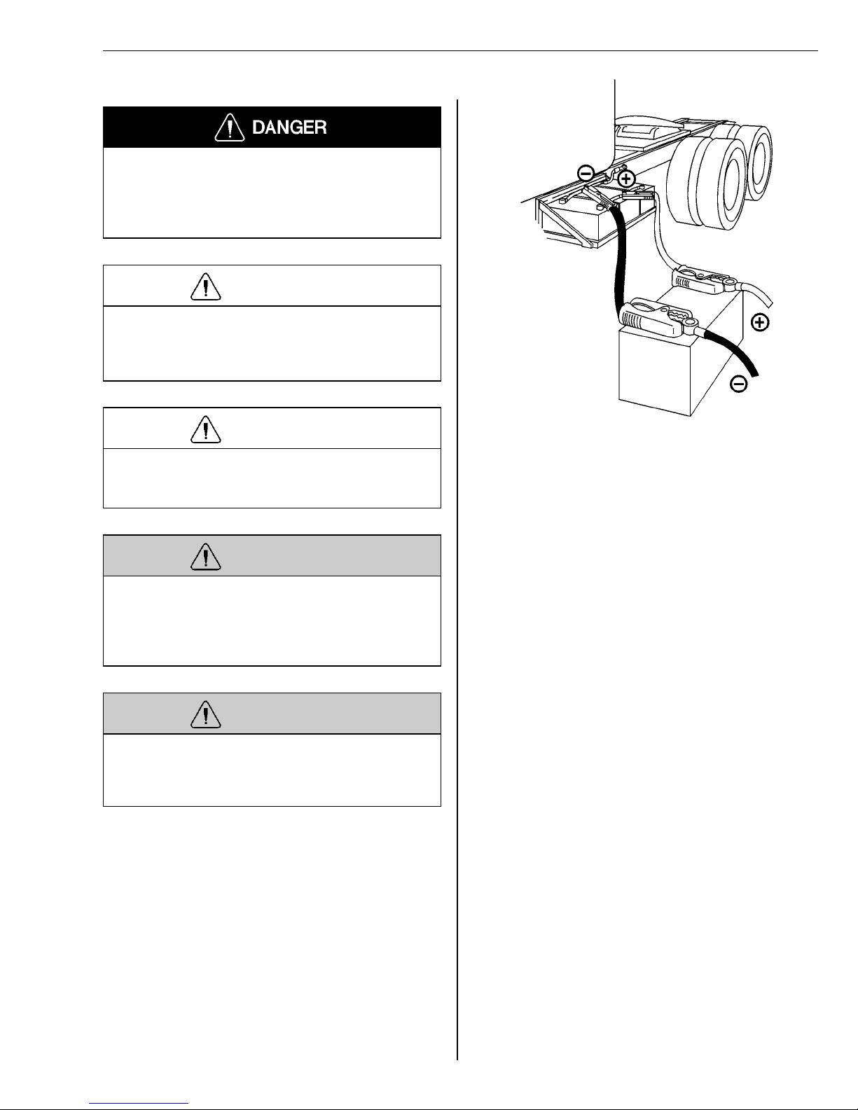
When jumping batteries to start an engine, it is important
that the jumper cables are connected directly from one
set of batteries in one vehicle to the other set of batteries in the other vehicle. This is so the cranking current is
carried through the proper starter wiring.
To access the batteries on a vehicle equipped with side
fairings, open the fairing access cover. “Jumper Studs”,
which are longer and made of brass, are factory installed
on one battery positive and negative post. These jumper
studs are designed to accept the jumper cable claws.
Connect the jumper cables to the positive, or “hot”
terminal first and the ground terminal last. When disconnecting the cables, disconnect the ground terminal first.
Connect the jumper cable clamps to the discharged battery first and to the booster battery last. Avoid creating
sparks by making all connections quickly and firmly. Do
not permit the vehicles to touch each other when jump
starting.
43
Page 48

Group 33 Starting and Charging VN, VHD Service Procedures
3111-03-02-02
Battery, Replacement (One or
Two)
Possible damage to electronic components. Turn the
vehicle ignition switch OFF before disconnecting or
connecting any electronic components. Failure to
de-energize circuits may result in permanent damage
to electronic components.
CAUTION
Before working on a vehicle, set the parking brakes,
place the transmission in neutral, and block the
wheels. Failure to do so can result in unexpected
vehicle movement and can cause serious personal injury or death.
WARNING
Always wear eye protection when working around batteries to prevent the risk of injury due to contact with
sulfuric acid or an explosion (If contacted with sulfuric
acid, flush immediately with water and get medical attention).
WARNING
Batteries may contain explosive gases. To help minimize the risks of explosion, avoid sparks or open
flames near batteries. Do not smoke when servicing
batteries.
Note: Some applications will require the removal of air
fairings, battery box covers, or other components to access the batteries.
Removal
1
Turn the ignition key to the “OFF” position.
2
Disconnect ground wiring from electrical equipment connected directly to
the batteries, such as ECU’s, satellite
systems, etc.
3
Disconnect the main ground cable(s)
at the batteries.
4
Disconnect the positive cable(s) at the
batteries.
CAUTION
If there are other ground cables connected to the battery (such as engine ECU’s, satellite system, etc.),
disconnect those grounds first, then remove the main
battery ground cable. Electronic modules may be
damaged when additional grounds are connected/disconnected without the main battery ground
connected. Disconnect the main battery ground last.
CAUTION
In vehicles with a Supplemental Restraint System
(SRS), turn the ignition switch ON before connecting
the battery. Failure to do so may result in permanent
damage to the instrument cluster or other electronic
circuits in the vehicle. This applies only to vehicles
with SRS and Cummins or Detroit Diesel engines.
Check for fault codes after repairs are complete.
5
Remove the battery nuts on all battery
connections and remove all cables
and wiring.
6
Loosen the battery hold down clamp
nuts enough to allow removal of the
hold down clamp assembly.
7
Remove the defective battery(s).
8
Clean any battery post or cable terminals as necessary.
Installation
9
Install the replacement battery(s). Observe that the battery positive and
negative posts are oriented properly
when installed.
44
Page 49
Group 33 Starting and Charging VN, VHD Service Procedures
10
Install the battery hold down clamp.
Torque =
24 ± 4 Nm
(18 ± 3 ft-lb)
11
Install all battery cables and wiring
connections removed in steps 5. Install
the battery nuts (hand tighten) securing those cables/wiring.
12
Connect the positive cables(s) and any
positive wiring from electrical equipment connected directly to the
batteries.
13
If the vehicle is equipped with a Supplemental Restraint System (SRS) and
a Cummins or Detroit Diesel engine,
turn the ignition switch to “ON” position. If not, leave the ignition switch in
the “OFF” position.
14
Connect the main ground cable(s).
Turn ignition switch back to “OFF” if
necessary.
24 ± 4 Nm
(18 ± 3 ft-lb)
3714-03-02-03
Battery Cables to Starter, Replacement
Before working on a vehicle, set the parking brakes,
place the transmission in neutral, and block the
wheels. Failure to do so can result in unexpected
vehicle movement and can cause serious personal injury or death.
WARNING
Always wear eye protection when working around batteries to prevent the risk of injury due to contact with
sulfuric acid or an explosion (If contacted with sulfuric
acid, flush immediately with water and get medical attention).
WARNING
Batteries may contain explosive gases. To help minimize the risks of explosion, avoid sparks or open
flames near batteries. Do not smoke when servicing
batteries.
15
Connect ground wiring from electrical
equipment connected directly to the
batteries.
16
Tighten all battery cable connections.
Torque =
13 ± 20 Nm
(10 –15 ft-lb)
13 ± 20 Nm
(10 –15 ft-lb)
CAUTION
If there are other ground cables connected to the battery (such as engine ECU’s, satellite system, etc.),
disconnect those grounds first, then remove the main
battery ground cable. Electronic modules may be
damaged when additional grounds are connected/disconnected without the main battery ground
connected. Disconnect the main battery ground last.
CAUTION
In vehicles with a Supplemental Restraint System
(SRS), turn the ignition switch ON before connecting
the battery. Failure to do so may result in permanent
damage to the instrument cluster or other electronic
circuits in the vehicle. This applies only to vehicles
with SRS and Cummins or Detroit Diesel engines.
Check for fault codes after repairs are complete.
45
Page 50

Group 33 Starting and Charging VN, VHD Service Procedures
4
CAUTION
Possible damage to electronic components. Turn the
vehicle ignition switch OFF before disconnecting or
connecting any electronic components. Failure to
de-energize circuits may result in permanent damage
to electronic components.
Disconnect the positive cable(s) at the
batteries.
5
Remove all support clips (brackets)
and cut cable ties.
Before you start the replacement of the battery to starter
cable(s), visually inspect the existing cables. Note the location of all routing, support clips (brackets), and cable
ties. If any area is visibly distressed take appropriate corrective actions to prevent damage to the replacement
cable(s). The following installation points should be observed always when replacing battery to starter cables.
Cables should be supported at no less than 600
•
mm (24 in.) intervals with non-conductive compres-
sion clips.
Cables must be supported as close as possible to
•
all cable bends.
Cable ties may be used as needed to prevent rela-
•
tive movement between cables.
Strain relief should be provided at terminals to pre-
•
vent terminal breakage.
Route cables to avoid sharp edges or abrasive ar-
•
eas.
Edges that cables pass through must be bushed
•
with suitable grommets.
Cables must not be routed within 130 mm (5 in.) of
•
engine exhaust components or other sources of in-
tense heat.
Cables should not be located in areas that experi-
•
ence routine exposure to diesel fuel, hydraulic fluid,
or oil.
Note: Some applications will require removal of air fair-
ings, battery box covers, or other components to access
the battery cables.
Removal
6
Disconnect the battery cables at the
starter. Note the wire positions to aid
in installation.
7
Remove the defective cable(s).
Installation
8
Position the replacement cable(s) in
the proper routing position. Be sure
the cable will connect to the starter
and batteries when all the support
clips are secure.
9
Install the battery cables and wiring at
the starter. Torque =
30.5 ± 3.5 Nm
(22.5 ± 2.5 ft-lb)
10
Install the cables into the support clips
and secure beginning at the starter
and working toward the battery. Observe the installation points as noted
above. Support Clip Torque =
18 ± 2 Nm
(13 ± 1.5 ft-lb)
Secure with cable ties as needed.
30.5 ± 3.5 Nm
(22.5 ± 2.5 ft-lb)
18 ± 2 Nm
(13 ± 1.5 ft-lb)
1
Turn the ignition key to the “OFF” position.
2
Disconnect ground wiring from the
electrical equipment connected directly
to the batteries, such as ECU’s, satellite systems, etc.
3
Disconnect the main ground cable(s)
at the batteries.
46
11
Connect the positive cable(s) and any
positive wiring from electrical equipment connected directly to the
batteries.
12
If the vehicle is equipped with a Supplemental Restraint System (SRS) and
a Cummins or Detroit Diesel engine,
turn the ignition switch to the “ON” position. If not, leave the ignition switch
in the “OFF” position.
Page 51

Group 33 Starting and Charging VN, VHD Service Procedures
13
Connect the main ground cable(s).
Turn ignition switch back to “OFF” if
necessary.
14
Connect ground wiring from the electrical equipment connected directly to
the batteries.
15
Tighten all battery cable connections.
Torque =
13 ± 20 Nm
(10 –15 ft-lb)
13 ± 20Nm
(10 –15 ft-lb)
3714-03-02-04
Battery Inter-connection Cables, Replacement
Before working on a vehicle, set the parking brakes,
place the transmission in neutral, and block the
wheels. Failure to do so can result in unexpected
vehicle movement and can cause serious personal injury or death.
WARNING
Always wear eye protection when working around batteries to prevent the risk of injury due to contact with
sulfuric acid or an explosion (If contacted with sulfuric
acid, flush immediately with water and get medical attention).
WARNING
Batteries may contain explosive gases. To help minimize the risks of explosion, avoid sparks or open
flames near batteries. Do not smoke when servicing
batteries.
CAUTION
If there are other ground cables connected to the battery (such as engine ECU’s, satellite system, etc.),
disconnect those grounds first, then remove the main
battery ground cable. Electronic modules may be
damaged when additional grounds are connected/disconnected without the main battery ground
connected. Disconnect the main battery ground last.
CAUTION
In vehicles with a Supplemental Restraint System
(SRS), turn the ignition switch ON before connecting
the battery. Failure to do so may result in permanent
damage to the instrument cluster or other electronic
circuits in the vehicle. This applies only to vehicles
with SRS and Cummins or Detroit Diesel engines.
Check for fault codes after repairs are complete.
47
Page 52

Group 33 Starting and Charging VN, VHD Service Procedures
10
CAUTION
Possible damage to electronic components. Turn the
vehicle ignition switch OFF before disconnecting or
connecting any electronic components. Failure to
de-energize circuits may result in permanent damage
to electronic components.
If the vehicle is equipped with a Supplemental Restraint System (SRS) and
a Cummins or Detroit Diesel engine,
turn the ignition switch to the “ON” position. If not, leave the ignition switch
in the “OFF” position.
Removal
1
Turn the ignition key to the “OFF” position.
2
Disconnect ground wiring from the
electrical equipment connected directly
to the batteries, such as the ECU’s,
satellite systems, etc.
3
Disconnect the main ground cable(s)
at the batteries.
4
Disconnect the positive cable(s) at the
batteries.
5
Remove the battery nuts on all battery
connections and remove all cables
and wiring.
11
Connect the main ground cable(s).
Turn the ignition switch back to “OFF”
if necessary.
12
Connect ground wiring from the electrical equipment connected directly to
the batteries.
13
Tighten all battery cable connections.
Torque =
13 ± 20 Nm
(10 –15 ft-lb)
13 ± 20 Nm
(10 –15 ft-lb)
6
Clean any battery post or cable terminals as necessary.
Installation
7
Replace the defective battery interconnecting cable(s).
8
Install all battery cables and wiring
connections removed in step five (5).
Install the battery nuts (hand tighten)
securing the cables/wiring.
9
Connect the positive cable(s) and positive wiring from the electrical
equipment connected directly to the
batteries.
48
Page 53
Group 33 Starting and Charging VN, VHD Service Procedures
3311-03-02-01
Starter Motor, Replacement
Volvo D12B or D12C Engine
Before working on a vehicle, set the parking brakes,
place the transmission in neutral, and block the
wheels. Failure to do so can result in unexpected
vehicle movement and can cause serious personal injury or death.
WARNING
Always wear eye protection when working around batteries to prevent the risk of injury due to contact with
sulfuric acid or an explosion (If contacted with sulfuric
acid, flush immediately with water and get medical attention).
WARNING
Batteries may contain explosive gases. To help minimize the risks of explosion, avoid sparks or open
flames near batteries. Do not smoke when servicing
batteries.
CAUTION
If there are other ground cables connected to the battery (such as engine ECU’s, satellite system, etc.),
disconnect those grounds first, then remove the main
battery ground cable. Electronic modules may be
damaged when additional grounds are connected/disconnected without the main battery ground
connected. Disconnect the main battery ground last.
CAUTION
Possible damage to electronic components. Turn the
vehicle ignition switch OFF before disconnecting or
connecting any electronic components. Failure to
de-energize circuits may result in permanent damage
to electronic components.
W3004732
See removal and installation procedures following
this illustration, for explanation of numbers 1 to 6
shown in above illustration.
Note: In some installations, the replacement of the
starter may be aided by the removal of additional components or wiring not referenced in this manual, or
affected by alternate battery cable routing due to alternate battery mounting locations.
Removal
1
Turn the ignition key to the “OFF” position.
2
Disconnect ground wiring from the
electrical equipment connected directly
to the batteries, such as the ECU’s,
satellite systems, etc.
3
Disconnect the main battery ground
cable(s).
4
Remove the splash shield.
5
Remove the inner fender assembly.
49
Page 54

Group 33 Starting and Charging VN, VHD Service Procedures
6
Loosen or remove the battery cable
mounting support brackets, if needed
to allow enough slack for removal of
the battery cable terminals at the
starter.
7
Remove the positive (1) and negative
(2) cables/wiring and “switch” terminal
(3) wire from the starter. Disconnect
the overcrank protection switch (4) (if
equipped). Note the cable/wiring position for installation.
8
Remove the engine ground terminal
connector (5).
9
Disconnect the engine wiring harness
connector (6). Remove the engine
wiring harness support clamp and pull
the harness away from the starter
area.
10
Remove the starter mounting bolts and
remove the starter from the vehicle.
14
Install the engine ground cables (5)
and secure.
Torque =
48 ± 8 Nm
(35 ± 6 ft-lb)
15
Install all starter wiring and cables.
(Battery cable terminals (1 & 2)
torque =
30.5 ± 3.5 Nm
(22.5 ± 2.5 ft-lb)
Switch terminal (3) torque =
2.6 ± 0.8 Nm
(23 ± 7 in-lb)
16
Secure the battery cables in the
mounting support brackets.
17
Install the inner fender assembly.
18
Install the splash shield.
19
Install the main ground cable(s).
48 ± 8 Nm
(35 ± 6 ft-lb)
30.5 ± 3.5 Nm
(22.5 ± 2.5 ft-lb)
2.6 ± 0.8 Nm.
(23 ± 7 in-lb)
Installation
11
Compare the orientation of the nose
housing on the old starter to the replacement starter. If necessary,
remove the nose housing on the replacement starter and “clock” it to the
position of the old starter.
Nose housing bolt torque =
10 ± 13 Nm
(13 – 17 ft-lb)
12
Install the replacement starter and secure the mounting bolts.
Torque =
85 ± 9 Nm
(63 ± 6.5 ft-lb)
13
Position the engine wiring harness and
engage the connector (6). Install the
engine wiring harness support clamp.
10 ± 13 Nm
(13 – 17 ft-lb)
85 ± 9 Nm
(63 ± 6.5 ft-lb)
20
Install ground wiring from the electrical
equipment connected directly to the
batteries.
21
Secure with the battery terminal nut(s).
Torque =
3.7 ± 5.7 Nm
(10 –15 ft-lb)
3.7 ± 5.7 Nm
(10 –15 ft-lb)
50
Page 55

Group 33 Starting and Charging VN, VHD Service Procedures
3311-03-02-01
Starter Motor, Replacement
Volvo D7C Engine
Before working on a vehicle, set the parking brakes,
place the transmission in neutral, and block the
wheels. Failure to do so can result in unexpected
vehicle movement and can cause serious personal injury or death.
WARNING
Always wear eye protection when working around batteries to prevent the risk of injury due to contact with
sulfuric acid or an explosion. (If contacted with sulfuric
acid, flush immediately with water and get medical attention).
If there are other ground cables connected to the battery (such as engine ECU’s, satellite system, etc.),
disconnect those grounds first, then remove the main
battery ground cable. Electronic modules may be
damaged when additional grounds are connected/disconnected without the main battery ground
connected. Disconnect the main battery ground last.
Possible damage to electronic components. Turn the
vehicle ignition switch OFF before disconnecting or
connecting any electronic components. Failure to
de-energize circuits may result in permanent damage
to electronic components.
CAUTION
CAUTION
WARNING
Never disconnect an air system component unless all
system pressure has been depleted. Failure to deplete system pressure before disconnecting hoses or
components may result in them separating violently,
causing serious eye and/or body injury.
WARNING
HOT ENGINE! Keep clear of all moving parts or hot
engine parts and/or fluids. A hot engine and/or fluids
can cause burns.
WARNING
Batteries may contain explosive gases. To help minimize the risks of explosion, avoid sparks or open
flames near batteries. Do not smoke when servicing
batteries.
W3004733
Starter D7C Engine
Dual Battery Cables shown.
1 Positive cables
2 Negative cables
3 Switch terminal
4 overcrank protection connector (with jumper)
5 Cable support bracket
6 EPG solenoid
7 EPG regulator
51
Page 56

Group 33 Starting and Charging VN, VHD Service Procedures
Note: In some installations, replacement of the starter
may be aided by removal of additional components or
wiring not referenced in this manual, or affected by alternate battery cable routing due to alternate battery
mounting locations.
Removal
1
Turn the ignition key to the “OFF” position.
2
Disconnect ground wiring from electrical equipment connected directly to
the batteries, such as ECU’s, satellite
systems, etc.
3
Disconnect the main battery ground
cable(s).
4
Remove the right inner fender assembly.
5
Remove the positive and negative cables and “switch” terminal wire from
the starter. Disconnect the overcrank
protection switch (if equipped). Note
the cable/wiring position for installation.
6
Remove the battery cable support
bracket which is below the starter and
pull the cables away from the starter
area (cables under starter routing).
Installation
9
Compare the orientation of the nose
housing on the old starter to the replacement starter. If necessary,
remove the nose housing on the replacement starter and “clock” it to the
position of the old starter.
Nose housing bolt torque =
18 ± 23 Nm (13 – 17 ft-lb)
10
Install the replacement starter and secure the mounting nuts.
Torque = 85 ± 15 Nm
(63 ± 6.5 ft-lb)
11
Install the EPG solenoid/regulator assembly. Install the EPG solenoid and
regulator air lines. Engage the EPG
solenoid connector.
12
Install the battery cable support
bracket below the starter.
13
Install all starter wiring and cables.
Battery cable terminals torque =
30.5 ± 3.5 Nm
(22.5 ± 2.5 ft-lb);
switch terminal torque =
2.6 ± 0.8 Nm
(23 ± 7 in-lb) Secure wiring with cable
ties as needed.
14
Install the right inner fender assembly.
18 ± 23 Nm
(13 – 17 ft-lb)
85 ± 9 Nm
(63 ± 6.5 ft-lb)
30.5 ± 3.5 Nm
(22.5 ± 2.5 ft-lb)
2.6 ± .08 Nm
(23 ± 7 in-lb)
7
Bleed all pressure from the vehicle air
system. Disconnect the Exhaust Pressure Governor (EPG) solenoid
connector. Note their position for installation, then disconnect the EPG
solenoid and regulator air lines. Remove the EPG solenoid/regulator
assembly for the engine.
8
Remove the starter mounting nuts and
remove the starter from the vehicle.
52
15
Install the main ground cable(s) onto
the battery ground terminal.
16
Install ground wiring from the electrical
equipment connected directly to the
batteries onto the battery ground terminal.
17
Tighten all battery cable connections.
Torque =
13 ± 20 Nm
(10 –15 ft-lb)
13 ± 20 Nm
(10 –15 ft-lb)
Page 57

Group 33 Starting and Charging VN, VHD Service Procedures
3311-03-02-01
Starter Motor, Replacement
Cummins or Detroit Diesel
Engine
Before working on a vehicle, set the parking brakes,
place the transmission in neutral, and block the
wheels. Failure to do so can result in unexpected
vehicle movement and can cause serious personal injury or death.
WARNING
Possible damage to electronic components. Turn the
vehicle ignition switch OFF before disconnecting or
connecting any electronic components. Failure to
de-energize circuits may result in permanent damage
to electronic components.
Note: In some installations, the replacement of the
starter may be aided by the removal of additional components or wiring not referenced in this manual, or
affected by alternate battery cable routing due to alternate battery mounting locations.
Removal
1
Turn the ignition key to the “OFF” position.
CAUTION
Always wear eye protection when working around batteries to prevent the risk of injury due to contact with
sulfuric acid or an explosion (If contacted with sulfuric
acid, flush immediately with water and get medical attention).
WARNING
HOT ENGINE! Keep clear of all moving parts or hot
engine parts and/or fluids. A hot engine and/or fulids
can cause burns.
CAUTION
In vehicles with a Supplemental Restraint System
(SRS), turn the ignition switch ON before connecting
the battery. Failure to do so may result in permanent
damage to the instrument cluster or other electronic
circuits within the vehicle. (This applies only to vehicles with SRS and a Cummins or Detroit Diesel
engine.) Always check for fault codes after repairs are
completed.
2
Disconnect ground wiring from the
electrical equipment connected directly
to the batteries, such as ECU’s, satellite systems, etc.
3
Disconnect the main battery ground
cable(s).
4
Remove the left splash shield.
5
Remove the left inner fender assembly.
6
Loosen or remove the battery cable
mounting support brackets and cable
dividers (if equipped) as needed to allow enough slack for removal of the
battery cable terminals at the starter.
Cut any cable ties as needed.
CAUTION
If there are other ground cables connected to the battery (such as engine ECU,’s satellite system, etc.),
disconnect those grounds first, then remove the main
battery ground cable. Electronic modules may be
damaged when additional grounds are connected/disconnected without the main battery ground
connected. Disconnect the main battery ground last.
7
Remove the positive and negative cables and “switch” terminal wire from
the starter. Disconnect the overcrank
protection switch (if equipped). Note
the cable/wiring position for installation.
8
Remove any wiring harness support
clamps and brackets as needed to access the starter mounting bolts and
allow removal of the starter.
53
Page 58

Group 33 Starting and Charging VN, VHD Service Procedures
9
Remove the starter mounting bolts
and remove the starter and spacer
(if equipped) from the vehicle.
Installation
10
Compare the orientation of the nose
housing on the old starter to the replacement starter. If necessary,
remove the nose housing on the replacement starter and “clock” it to the
position of the old starter.
Nose housing bolt torque =
9.5 ± 12.5 Nm
(13 –17 ft-lb)
11
Install the replacement starter and
spacer (if equipped) and secure the
mounting bolts. Torque =
176 ± 25 Nm
(130 ± 18 ft-lb)
9.5 ± 12.5 Nm
(13 –17 ft-lb)
176 ± 25 Nm
(130 ± 18 ft-lb)
18
Install the main ground cable(s). Turn
ignition switch back to “OFF” if necessary.
19
Install ground wiring from electrical
equipment connected directly to the
batteries.
20
Secure with the battery terminal nuts.
Torque =
3.7 ± 5.7 Nm
(10 –15 ft-lb)
3.7 ± 5.7 Nm
(10 –15 ft-lb)
12
Install any wiring harness support
clamps and brackets removed to access the starter mounting bolts.
13
Install all starter wiring and cables.
(Battery cable terminals torque =
30.5 ± 3.5 Nm
(22.5 ± 2.5 ft-lb);
switch terminal torque =
2.6 ± 0.8 Nm
(23 ± 7 in-lb)
14
Secure the battery cables in the
mounting support brackets and cable
dividers. Secure with cable ties as
needed.
15
Install the inner fender assembly.
16
Install the splash shield.
30.5 ± 3.5 Nm
(22.5 ± 2.5 ft-lb)
2.6 ± 0.8 Nm
(23 ± 7 in-lb)
17
If the vehicle is equipped with a Supplemental Restraint System (SRS),
turn the ignition switch to the “ON” position. If not, leave the ignition switch
in the “OFF” position.
54
Page 59
Group 33 Starting and Charging VN, VHD Service Procedures
3331-03-02-02
Preheater Fuse, Replacement
Before working on a vehicle, set the parking brakes,
place the transmission in neutral, and block the
wheels. Failure to do so can result in unexpected
vehicle movement and can cause serious personal injury or death.
WARNING
HOT ENGINE! Keep clear of all moving parts or hot
engine parts and/or fluids. A hot engine and/or fluids
can cause burns.
W3004715
WARNING
Batteries may contain explosive gases. To help minimize the risks of explosion, avoid sparks or open
flames near batteries. Do not smoke when servicing
batteries.
The preheat fuse assembly includes a support (1) designed to protect the fuse (2) from physical damage. The
support is also used as a path for current flow and a
connection point (3) for the fuse on the long fuse assembly used in the D12 engines.
CAUTION
If there are other ground cables connected to the battery (such as engine ECU,’s satellite system, etc.),
disconnect those grounds first, then remove the main
battery ground cable. Electronic modules may be
damaged when additional grounds are connected/disconnected without the main battery ground
connected. Disconnect the main battery ground last.
CAUTION
Possible damage to electronic components. Turn the
vehicle ignition switch OFF before disconnecting or
connecting any electronic components. Failure to
de-energize circuits may result in permanent damage
to electronic components.
CAUTION
Use caution when working around the preheat
elements. When active, the elements will heat to approximately (705
the elements to cool to avoid severe burns.
C) 1300F. Allow sufficient time for
55
Page 60

Group 33 Starting and Charging VN, VHD Service Procedures
Removal
1
Turn the ignition key to the “OFF” position.
2
Disconnect ground wiring from the
electrical equipment connected directly
to the batteries, such as ECU’s, satellite systems, etc.
3
Disconnect the battery main ground
cable(s).
4
Remove the nuts securing the defective fuse assembly(s).
5
Remove the wiring, support and fuse.
Installation
6
If the defective fuse assembly is the
long fuse assembly on the D12 engine, remove the screw securing the
fuse to the support. Install the replacement fuse onto the support and
secure with the screw.
3331-03-02-03
Preheater Relay, Replacement
Volvo D12B or D12C Engine
Before working on a vehicle, set the parking brakes,
place the transmission in neutral, and block the
wheels. Failure to do so can result in unexpected
vehicle movement and can cause serious personal injury or death.
WARNING
HOT ENGINE! Keep clear of all moving parts or hot
engine parts and/or fluids. A hot engine and/or fluids
can cause burns.
CAUTION
If there are other ground cables connected to the battery (such as engine ECU’s, satellite system, etc.),
disconnect those grounds first, then remove the main
battery ground cable. Electronic modules may be
damaged when additional grounds are connected/disconnected without the main battery ground
connected. Disconnect the main battery ground last.
7
Install the replacement fuse, with support and wiring, onto the mounting
terminals and secure.
8
Install the main ground cable(s).
9
Install ground wiring from the electrical
equipment directly to the batteries.
10
Secure with the battery terminal nut(s).
Torque =
3.7 ± 5.7 Nm
(10 – 15 ft-lb)
3.7 ± 5.7 Nm
(10 – 15 ft-lb)
CAUTION
Possible damage to electronic components. Turn the
vehicle ignition switch OFF before disconnecting or
connecting any electronic components. Failure to
de-energize circuits may result in permanent damage
to electronic components.
CAUTION
Use caution when working around the preheat
elements. When active, the elements will heat to approximately (705
the elements to cool to avoid severe burns.
C) 1300F. Allow sufficient time for
56
Page 61

Group 33 Starting and Charging VN, VHD Service Procedures
Removal
1
Turn the ignition key to the “OFF” position.
2
Disconnect ground wiring from electrical equipment connected directly to
the batteries, such as ECU’s, satellite
systems, etc.
3
Disconnect the battery main ground
cable(s).
4
Remove the power cable, fuse, and
wiring from relays. Note position for reassembly.
5
Remove the support bracket/wiring
harness clamp bolts (VN) or fan ring
support bracket (VHD).
6
Remove the charge air pipe hose
clamp.
7
Remove the charge air piping/preheater mounting bolts and
remove the charge air piping from the
vehicle.
12
Tap the relay mounting bracket onto
the element block.
13
Install the preheater element block,
with new gaskets, and the charge air
piping to the intake manifold.
14
Secure with mounting bolts.
Torque =
24 ± 4 Nm
(18 ± 3 ft-lb)
15
Install and secure the charge air pipe
hose clamp.
16
Install the support bracket/wiring harness clamp bolts (VN) or fan ring
support bracket (VHD) and secure.
17
Install the power cable, fuse, and
wiring to the relays and secure.
18
Install the main ground cable(s).
19
Install ground wiring from the electrical
equipment connected directly to the
batteries.
24 ± 4 Nm
(18 ± 3 ft-lb)
8
Remove the preheater element block
from the intake manifold. Tap the relay
mounting bracket off the element
block.
9
Remove the relay(s) from the mounting bracket.
Installation
10
Install the replacement relay(s) onto
the bracket and secure.
11
Clean the gasket surfaces.
20
Secure with the battery terminal nut(s).
Torque =
3.7 ± 5.7Nm
(10 –15 ft-lb)
3.7 ± 5.7Nm
(10 –15 ft-lb)
57
Page 62

Group 33 Starting and Charging VN, VHD Service Procedures
3331-03-02-03
Preheater Relay, Replacement
D7C Engine
Before working on a vehicle, set the parking brakes,
place the transmission in neutral, and block the
wheels. Failure to do so can result in unexpected
vehicle movement and can cause serious personal injury or death.
WARNING
HOT ENGINE! Keep clear of all moving parts or hot
engine parts and/or fluids. A hot engine and /or fluids
can cause burns.
CAUTION
2
Disconnect ground wiring from the
electrical equipment connected directly
to the batteries, such as ECU’s, satellite systems, etc.
3
Disconnect the battery main ground
cable(s).
4
Remove the power cable, fuse, and
wiring from relay. Note position for reassembly.
5
Remove the relay from its mounting
and remove from the vehicle.
Installation
6
Install the replacement relay and secure.
If there are other ground cables connected to the battery (such as engine ECU’s, satellite system, etc.),
disconnect those grounds first, then remove the main
battery ground cable. Electronic modules may be
damaged when additional grounds are connected/disconnected without the main battery ground
connected. Disconnect the main battery ground last.
CAUTION
Possible damage to electronic components. Turn the
vehicle ignition switch OFF before disconnecting or
connecting any electronic components. Failure to
de-energize circuits may result in permanent damage
to electronic components.
CAUTION
Use caution when working around the preheat
elements. When active, the elements will heat to approximately (705
the elements to cool to avoid severe burns.
C) 1300F. Allow sufficient time for
7
Install the power cable, fuse and
wiring to the relay and secure.
8
Install the main ground cable(s).
9
Install ground wiring from the electrical
equipment connected directly to the
batteries.
10
Secure with the battery terminal nut(s)
Torque =
3.7 ± 5.7 Nm
(10 –15 ft-lb)
3.7 ± 5.7 Nm
(10 –15 ft-lb)
Removal
1
Turn the ignition key to the “OFF” position.
58
Page 63
Group 33 Starting and Charging VN, VHD Service Procedures
3331-03-02-01
Preheater Element, Replacement
D12B or D12C Engine
Before working on a vehicle, set the parking brakes,
place the transmission in neutral, and block the
wheels. Failure to do so can result in unexpected
vehicle movement and can cause serious personal injury or death.
WARNING
HOT ENGINE! Keep clear of all moving parts or hot
engine parts and/or fluids. A hot engine and /or fluids
can cause burns.
Use caution when working around the preheat
elements. When active, the elements will heat to approximately 705
the elements to cool to avoid severe burns.
CAUTION
C (1300F.). Allow sufficient time for
CAUTION
If there are other ground cables connected to the battery (such as engine ECU’s, satellite system, etc.),
disconnect those grounds first, then remove the main
battery ground cable. Electronic modules may be
damaged when additional grounds are connected/disconnected without the main battery ground
connected. Disconnect the main battery ground last.
CAUTION
Possible damage to electronic components. Turn the
vehicle ignition switch OFF before disconnecting or
connecting any electronic components. Failure to
de-energize circuits may result in permanent damage
to electronic components.
W3004730
Removal
1
Turn the ignition key to the “OFF” position.
2
Disconnect ground wiring from electrical equipment connected directly to
the batteries, such as ECU’s, satellite
systems, etc.
3
Disconnect the battery main ground
cable(s).
4
Remove the power cable, fuses, and
wiring from relays. Note position for reassembly.
5
Remove the support bracket/wiring
harness clamp bolts (6, VN only) or
fan ring support bracket (5, VHD only).
59
Page 64

Group 33 Starting and Charging VN, VHD Service Procedures
6
Remove the charge air pipe hose
clamp.
7
Remove the charge air piping / preheater mounting bolts (3) and remove
the charge air piping (4) from the vehicle.
8
Remove the preheater element block
(1) from the intake manifold. Tap the
relay mounting bracket off the element
block.
9
Clean the gasket surfaces.
Installation
10
Tap the relay mounting bracket onto
the replacement element block.
17
Secure with the battery terminal nut(s).
Torque =
3.7 ± 5.7 Nm
(10 –15 ft-lb)
3.7 ± 5.7 Nm
(10 –15 ft-lb)
3331-03-02-01
Preheater Element, Replacement
D7C Engine
Before working on a vehicle, set the parking brakes,
place the transmission in neutral, and block the
wheels. Failure to do so can result in unexpected
vehicle movement and can cause serious personal injury or death.
WARNING
11
Install the preheater element block,
with new gaskets (2), and the charge
air piping to the intake manifold. Secure with mounting bolts.
Torque =
24 ± 4 Nm
(18 ± 3 ft-lb)
12
Install and secure the charge air pipe
hose clamp.
13
Install the support bracket/wiring harness clamp bolts (VN) or fan ring
support bracket (VHD) and secure.
14
Install the power cable, fuse and
wiring to the relays and secure.
15
Install the main ground cable(s).
16
Install ground wiring from the electrical
equipment connected directly to the
batteries.
24 ± 4 Nm
(18 ± 3 ft-lb)
HOT ENGINE! Keep clear of all moving parts or hot
engine parts and/or fluids. A hot engine and /or fluids
can cause burns.
CAUTION
If there are other ground cables connected to the battery (such as engine ECU’s, satellite system, etc.),
disconnect those grounds first, then remove the main
battery ground cable. Electronic modules may be
damaged when additional grounds are connected/disconnected without the main battery ground
connected. Disconnect the main battery ground last.
CAUTION
Possible damage to electronic components. Turn the
vehicle ignition switch OFF before disconnecting or
connecting any electronic components. Failure to
de-energize circuits may result in permanent damage
to electronic components.
CAUTION
Use caution when working around the preheat
elements. When active, the elements will heat to approximately 705
the elements to cool to avoid severe burns.
C (1300F.). Allow sufficient time for
60
Page 65

Group 33 Starting and Charging VN, VHD Service Procedures
Removal
1
Turn the ignition key to the “OFF” position.
2
Disconnect ground wiring from the
electrical equipment connected directly
to the batteries, such as ECU’s, satellite systems etc.
3
Disconnect the battery main ground
cable(s).
4
Remove the power cable, fuse and
wiring from relay. Note position for reassembly.
5
Remove the relay from its mounting
and remove from the vehicle.
12
Install the ground wire from the preheater element block.
13
Install the charge air piping. Secure
the mounting bolts at the preheat element block.
Torque =
24 ± 4 Nm
(18 ± 3 ft-lb)
secure the mounting bolts at the fan
ring.
14
Install and secure the charge air pipe
hose clamp.
15
Install the relay and secure.
16
Install the power cable, fuse and
wiring to the relay and secure.
24 ± 4 Nm
(18 ± 3 ft-lb)
6
Remove the charge air pipe hose
clamp.
7
Remove the charge air piping mounting bolts at the fan ring and preheater
and remove the vehicle.
8
Remove the ground wire from the preheater element book.
9
Remove the preheater element block
from the intake manifold.
10
Clean the gasket surfaces.
Installation
11
Install new gasket between intake
manifold and replacement preheater
element block. Install the preheater element block. Install new gasket on the
intake side of the preheater element
block.
17
Install the main ground cable(s).
18
Install ground wiring from electrical
equipment connected directly to the
batteries.
19
Secure with the battery terminal nut(s).
Torque =
3.7 ± 5.7 Nm
(10 –15 ft-lb)
3.7 ± 5.7 Nm
(10 –15 ft-lb)
61
Page 66
Group 33 Starting and Charging VN, VHD Service Procedures
3211-03-02-03
Alternator, Replacement (Adjustable Mount)
Possible damage to electronic components. Turn the
vehicle ignition switch OFF before disconnecting or
connecting any electronic components. Failure to
de-energize circuits may result in permanent damage
to electronic components.
CAUTION
Before working on a vehicle, set the parking brakes,
place the transmission in neutral, and block the
wheels. Failure to do so can result in unexpected
vehicle movement and can cause serious personal injury or death.
WARNING
HOT ENGINE! Keep clear of all moving parts or hot
engine parts and/or fluids. A hot engine and /or fluids
can cause burns.
CAUTION
If there are other ground cables connected to the battery (such as engine ECU’s, satellite system, etc.),
disconnect those grounds first, then remove the main
battery ground cable. Electronic modules may be
damaged when additional grounds are connected/disconnected without the main battery ground
connected. Disconnect the main battery ground last.
Note: In some installations, the replacement of the alternator may be aided by the removal of splash shields.
Removal
1
Turn the ignition key to the “OFF” position.
2
Disconnect ground wiring from the
electrical equipment connected directly
to the batteries, such as ECU’s, satellite systems, etc.
3
Disconnect the main ground cable(s).
4
Disconnect all alternator wiring. Note
wire positions to aid in installation.
5
Loosen the alternator mounting bolts.
CAUTION
In vehicles with a Supplemental Restraint System
(SRS), turn the ignition switch ON before connecting
the battery. Failure to do so may result in permanent
damage to the instrument cluster or other electronic
circuits in the vehicle. This applies only to vehicles
with SRS and Cummins or Detroit Diesel engines.
Check for fault codes after repairs are complete.
62
6
Loosen the tensioner bolt as needed
and remove the belt from the pulley.
7
Remove the alternator mounting bolts
and remove the alternator from the vehicle.
Installation
8
If necessary, remove the pulley from
the alternator and install it on the replacement alternator. Torque =
109 ± 11 Nm
(80 ± 8 ft-lb)
9
Install the replacement alternator and
tensioner. Leave bolts loose enough to
adjust belt tension.
109 ± 11 Nm
(80 ± 8 ft-lb)
Page 67

Group 33 Starting and Charging VN, VHD Service Procedures
10
Adjust the tensioner as needed to
achieve a belt tension of 111 Nm (150
ft-lb) for a new belt or 73 Nm (100 ftlb) for a used belt. Use Belt Tension
Gauge J-23600–B, or equivalent tool,
to check tension.
11
Tighten the alternator adjustment
mounting bolt.
Torque =
48 ± 8 Nm
(34 ± 6 ft-lb)
12
Tighten the alternator pivot mounting
bolt.
Torque =
88 ± 7 Nm
(65 ± 5 ft-lb)
13
Connect all alternator wiring. Torque =
48 ± 8 Nm
(34 ± 6 ft-lb)
88 ± 7 Nm
(65 ± 5 ft-lb)
3211-03-02-04
Alternator, Replacement (Fixed
Mount)
Before working on a vehicle, set the parking brakes,
place the transmission in neutral, and block the
wheels. Failure to do so can result in unexpected
vehicle movement and can cause serious personal injury or death.
WARNING
HOT ENGINE! Keep clear of all moving parts or hot
engine parts and/or fluids. A hot engine and /or fluids
can cause burns.
CAUTION
BATTERY TERMINAL 6.5 ± 0.5 Nm (58 ± 5 in-lb)
GROUND TERMINAL 6.2 ± 0.5 Nm (55 ± 5 in-lb)
"I" TERMINAL 2.3 ± 0.5 Nm (20 ± 5 in-lb)
"R" TERMINAL 2.3 ± 0.5 Nm (20 ± 5 in-lb)
14
If the vehicle is equipped with a Supplemental Restraint System (SRS) and
a Cummins or Detroit Diesel engine,
turn the ignition switch to the “ON” position. If not, leave the ignition switch
in the “OFF” position.
15
Connect the main ground cable(s).
Turn ignition switch back to “OFF” if
necessary.
16
Connect ground wiring from the electrical equipment connected directly to
the batteries
If there are other ground cables connected to the battery (such as engine ECU’s, satellite system, etc.),
disconnect those grounds first, then remove the main
battery ground cable. Electronic modules may be
damaged when additional grounds are connected/disconnected without the main battery ground
connected. Disconnect the main battery ground last.
CAUTION
In vehicles with a Supplemental Restraint System
(SRS), turn the ignition switch ON before connecting
the battery. Failure to do so may result in permanent
damage to the instrument cluster or other electronic
circuits in the vehicle. This applies only to vehicles
with SRS and Cummins or Detroit Diesel engines.
Check for fault codes after repairs are complete.
17
Tighten all battery cable connections.
Torque =
13 ± 20 Nm
(10 –15 ft-lb)
13 ± 20 Nm
(10 –15 ft-lb)
63
Page 68

Group 33 Starting and Charging VN, VHD Service Procedures
9
CAUTION
Possible damage to electronic components. Turn the
vehicle ignition switch OFF before disconnecting or
connecting any electronic components. Failure to
de-energize circuits may result in permanent damage
to electronic components.
Note: In some installations, the replacement of the alternator may be aided by the removal of splash shields.
Removal
1
Turn the ignition key to the “OFF” position.
2
Disconnect the ground wiring electrical
equipment connected directly to the
batteries, such as ECU’s, satellite systems, etc.
3
Disconnect the main ground cable(s).
Use fan belt tensioner tool J-44392, or
equivalent tool, to release the pressure from the automatic belt tensioner
and install the belt onto the alternator
pulley.
10
Connect all alternator wiring. Torque =
BATTERY TERMINAL 6.5 ± 0.5 Nm (58 ± 5 in-lb)
GROUND TERMINAL 6.2 ± 0.5 Nm (55 ± 5 in-lb)
"I" TERMINAL 2.3 ± 0.5 Nm (20 ± 5 in-lb)
"R" TERMINAL 2.3 ± 0.5 Nm (20 ± 5 in-lb)
11
If the vehicle is equipped with a Supplemental Restraint System (SRS) and
a Cummins or Detroit Diesel engine,
turn the ignition switch to the “ON” position. If not, leave the ignition in the
“OFF” position.
4
Disconnect all alternator wiring. Note
wire positions to aid in installation.
5
Use fan belt tensioner tool J-44392, or
equivalent tool, to release the pressure from the automatic belt tensioner
and remove the belt from the alternator pulley.
6
Remove the alternator mounting bolts
and remove the alternator from the vehicle.
Installation
7
If necessary, remove the pulley from
the alternator and install it on the replacement alternator. Torque =
109 ± 11 Nm
(80 ± 8 ft-lb)
109 ± 11 Nm
(80 ± 8 ft-lb)
12
Connect the main ground cable(s).
Turn ignition switch back to “OFF” if
necessary.
13
Connect ground wiring from the electrical equipment connected directly to
the batteries.
14
Tighten all battery cable connections.
Torque =
3.7 ± 5.7 Nm
(10 –15 ft-lb)
3.7 ± 5.7 Nm
(10 –15 ft-lb)
8
Install the replacement alternator and
tighten the mounting bolts.
Torque =
88 ± 7 Nm
(65 ± 5 ft-lb)
64
88 ± Nm
(65 ± 5 ft-lb)
Page 69

Feedback
One of our objectives is that workshop personnel should have access to correct and
appropriate service manuals where it concerns fault tracing, repairs and maintenance
of Volvo trucks.
In order to maintain the high standards of our literature, your opinions and experience
when using this manual would be greatly appreciated.
If you have any comments or suggestions, make a copy of this page, write down your
comments and send them to us, either via telefax or mailing directly to the address
listed below.
To
Volvo Trucks North America, Inc.
Dept. 516 Service Publications
7900 National Service Road
P.O. Box 26115
Greensboro, NC 27402-6115
USA
Fax (336) 393-3170
Comments/proposals
................................................................................................................................................................................
................................................................................................................................................................................
................................................................................................................................................................................
................................................................................................................................................................................
From
..........................................................................
..........................................................................
..........................................................................
..........................................................................
..........................................................................
..........................................................................
..........................................................................
................................................................................................................................................................................
................................................................................................................................................................................
................................................................................................................................................................................
................................................................................................................................................................................
................................................................................................................................................................................
................................................................................................................................................................................
................................................................................................................................................................................
................................................................................................................................................................................
................................................................................................................................................................................
Concerns Service Manual: ...............................................................................................................................
Page 70

Operation Numbers
3111-03-02-02 Battery, Replacement (One or Two) . ......................44
3211-03-02-03 Alternator, Replacement (Adjustable Mount) . . . . . . . . ...........62
3211-03-02-04 Alternator, Replacement (Fixed Mount) ......................63
3311-03-02-01 Starter Motor, Replacement . . . . . ..................49,51,53
3331-03-02-01 Preheater Element, Replacement . . ....................59,60
3331-03-02-02 Preheater Fuse, Replacement . . . . ......................55
3331-03-02-03 Preheater Relay, Replacement . . . . ....................56,58
3714-03-02-03 Battery Cables to Starter, Replacement . . . . . . . . . . ...........45
3714-03-02-04 Battery Inter-connection Cables, Replacement . . . . . . . ...........47
3714-19-03-01 Battery Cables, Removal and Installation . . . . . . . . . . ...........41
Page 71

Page 72

PV776-TSP146025 (0000) 01.2001 © Volvo Trucks North America, Inc., 2001
Volvo Trucks North America, Inc.
P.O. Box 26115, Greensboro, NC 27402-6115
Volvo Trucks Canada, Ltd.
6490 Vipond Drive, Mississauga, Ontario L5T 1W8
http://www.volvotrucks.volvo.com
 Loading...