

Page 1

Foreword
This booklet is part of a complete service manual. Read the
foreword in the service manual.
WARNING
Always read the booklet Safety before proceeding.
PUB 2012.10
1
Page 2

Page 3

Table of contents
03 SPECIFICATIONS
030 General
Tightening torque, cylinder head ................................................................ 6
Engine, specification
General ..................................................................................................... 6
Cylinder block, specifications ...................................................................... 7
Engine transmission, tightening torque ....................................................... 7
Tightening torques .................................................................................... 7
Timing gear casing ................................................................................... 9
Tightening torques, flywheel housing WLO/EXC .................................... 11
Tightening torques, timing gear plate ..................................................... 11
Engine transmission, specification ............................................................ 12
Rocker arm shaft, tightening torques ........................................................ 13
Valve mechanism, specifications .............................................................. 14
Valve mechanism, tightening torques ....................................................... 16
Tightening torques, valve cover ................................................................ 16
Oil sump, tightening torque ....................................................................... 16
Oil cooler, tightening torques .................................................................... 17
Oil cooler ................................................................................................. 17
Oil cooler, cover ...................................................................................... 17
Cylinder block, tightening torques ............................................................. 18
Engine mount incl. bracket ..................................................................... 18
Ladder frame .......................................................................................... 19
Inlet ......................................................................................................... 19
Tightening torque, fuel system .................................................................. 21
Exhaust manifold, tightening torques ........................................................ 21
Turbocharger, tightening torques .............................................................. 21
Crank mechanism, specifications ............................................................. 23
Crankshaft, tightening torques .................................................................. 25
Flywheel, tightening torques ..................................................................... 26
Belt pulley/vibration damper, tightening torques ....................................... 27
................................................................................... 6
21 ENGINE
210 General, common info about 211 - 218
Engine, mounting in work stand ................................................................ 28
Engine, dismantling .................................................................................. 32
Cylinder liners, removing ........................................................................ 39
Engine, assembling .................................................................................. 40
Cylinder liners, installing ......................................................................... 41
Crankshaft, installing .............................................................................. 43
Pistons, installing .................................................................................... 44
Installing timing gear plate ...................................................................... 45
Flywheel housing .................................................................................... 49
Crankshaft seal, rear .............................................................................. 50
Front crankshaft seal .............................................................................. 51
Speed (rpm) sensor, adjusting ................................................................ 54
Engine, removing from work stand ........................................................... 56
211 Cylinder head
Cylinder head, removing ........................................................................... 59
Cylinder head, reconditioning ................................................................... 62
Installing in work stand ........................................................................... 62
Valves, removing .................................................................................... 63
Sleeve for unit injector, removing ........................................................... 64
Tap out with drift ..................................................................................... 65
Pull out with puller ................................................................................... 65
Valve guide, checking ............................................................................. 67
Valve guides, changing ........................................................................... 68
3
Page 4

Injector sleeve, installing ......................................................................... 69
Cylinder head, checking for leaks
Valve seat, checking ............................................................................... 73
Valve seat, cleaning soot and grinding ................................................... 73
Valve seat, changing .............................................................................. 73
Valves, grinding ...................................................................................... 74
Cylinder head, assembling ..................................................................... 74
Cylinder head, fitting ................................................................................. 76
212 Cylinder block with crankcase ventilation
Cylinder block, liners removed, milling of all liner locations ...................... 82
214 Valve mechanism
Valves, adjusting ....................................................................................... 88
Inlet valves, checking and adjusting ....................................................... 89
Unit injectors, adjusting ........................................................................... 89
Exhaust valves, checking and adjusting ................................................. 90
...........................................................
22 LUBRICATING SYSTEM
223 Oil cooler
Oil cooler, leakage check .......................................................................... 91
71
4
Page 5

GENERAL
03 SPECIFICATIONS
030 General
5
Page 6
13
36 35
9
28 27
6
22 21
1
15 16
3
23 24
7
31 32
11
14
38 37
10
30 29
4
18 17
2
19 20
5
25 26
8
33 34
12
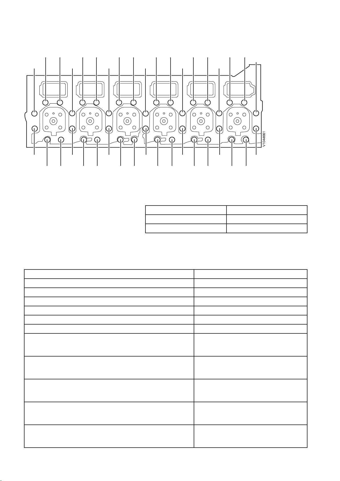
Fig.1 Cylinder head, D13
Tightening torque, cylinder head
NOTE!
Tighten the bolts in the sequence shown in the figure.
Step 1 100±5Nm(74±3.7 lbf ft)
Step 2 120±5° Angle-tightening
Step 3 90±5° Angle-tightening
Engine, specification
General
D13 F
Number of cylinders 6
Cylinder bore 131 mm (5.16 in)
Stroke 158 mm (6.22 in)
Displacement 12.78 litres (3.38 US gal)
Injection order 1–5–3–6–2–4
Compression ratio 18, 5:1
Low idle
EXC
WLO
High idle
EXC
WLO
Max. full load rpm
EXC
WLO
Weight, engine
EXC
WLO
Total length
EXC
WLO
13.33 r/s (800 rpm)
11.67 r/s (700 rpm)
28.33 r/s (1700 rpm)
31.67 r/s (1,900 rpm)
31.67 r/s (1,900 rpm)
35 r/s (2,100 rpm)
1,330 kg (3,042 lbs)
1,330 kg (3,042 lbs)
1 585 mm (62.4 in)
1460 mm (57.5 in)
6
Page 7
D13 F
Width
EXC
WLO
Height
EXC
WLO
789 mm (31.1 in)
1077 mm (42.4 in)
1 250 mm (49.2 in)
1 215 mm (47.8 in)
Cylinder block, specifications
Length 1 052 mm (41.42 in)
Height, upper block face-crankshaft centre 422 mm (16.6 in)
Height, lower block face-crankshaft centre 120 mm (4.72 in)
Cylinder liners
Type Wet, replaceable
Sealing surface's height over cylinder block's face 0.15 – 0.21 mm (0.0059 — 0.0083 in)
Number of seal rings per cylinder liner 3
Engine transmission, tightening torque
Tightening torques
NOTE!
Tighten in the order shown in the figure.
7
Page 8
V1071860
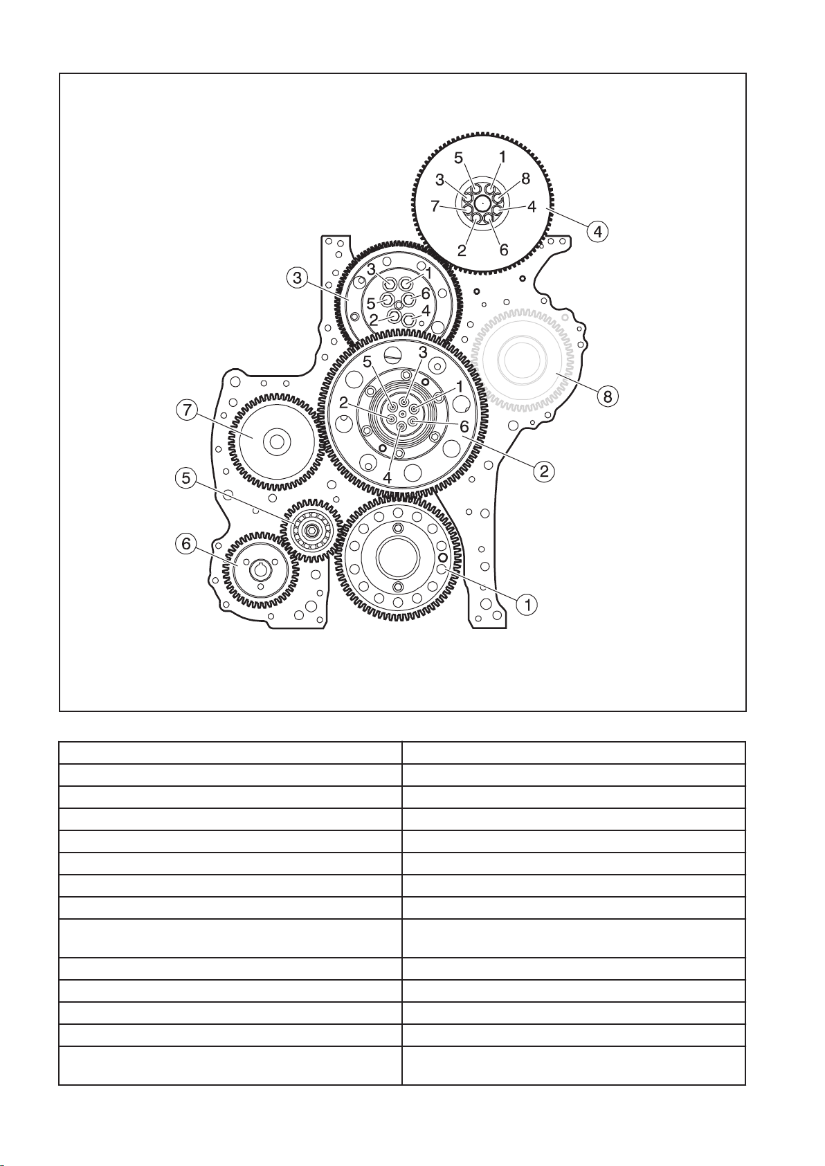
Fig.2
Gears: Tightening torque:
1. Drive gear, crankshaft 24±4 Nm (18±3 lbf ft)
2. Transfer gear, outer gear:
step 1: 25±3 Nm (18.4±2.2 lbf ft)
step 2: angle-tightening 110±5°
3. Transfer gear, adjustable:
step 1: 35±4 Nm (25.8±2.95 lbf ft)
step 2: angle-tightening 120° ±5°
4. Gear, camshaft: Vibration damper's 8.8-bolts may not
be reused.
temporarily: 10 Nm (7.5 lbf ft)
step 1: 45±5 Nm (33±4 lbf ft)
step 2: Angle-tightening 90° ±5°
5. Transfer gear 140±10 Nm (103±7.4 lbf ft)
6. Drive gear, lubrication oil pump for power take-off and
100±10 Nm (74±7.4 lbf ft)
fuel feed pump
8
Page 9
7. Drive gear, compressor 200+50/-0 Nm (148+37/-0 lbf ft)
V1088409
8. Not used
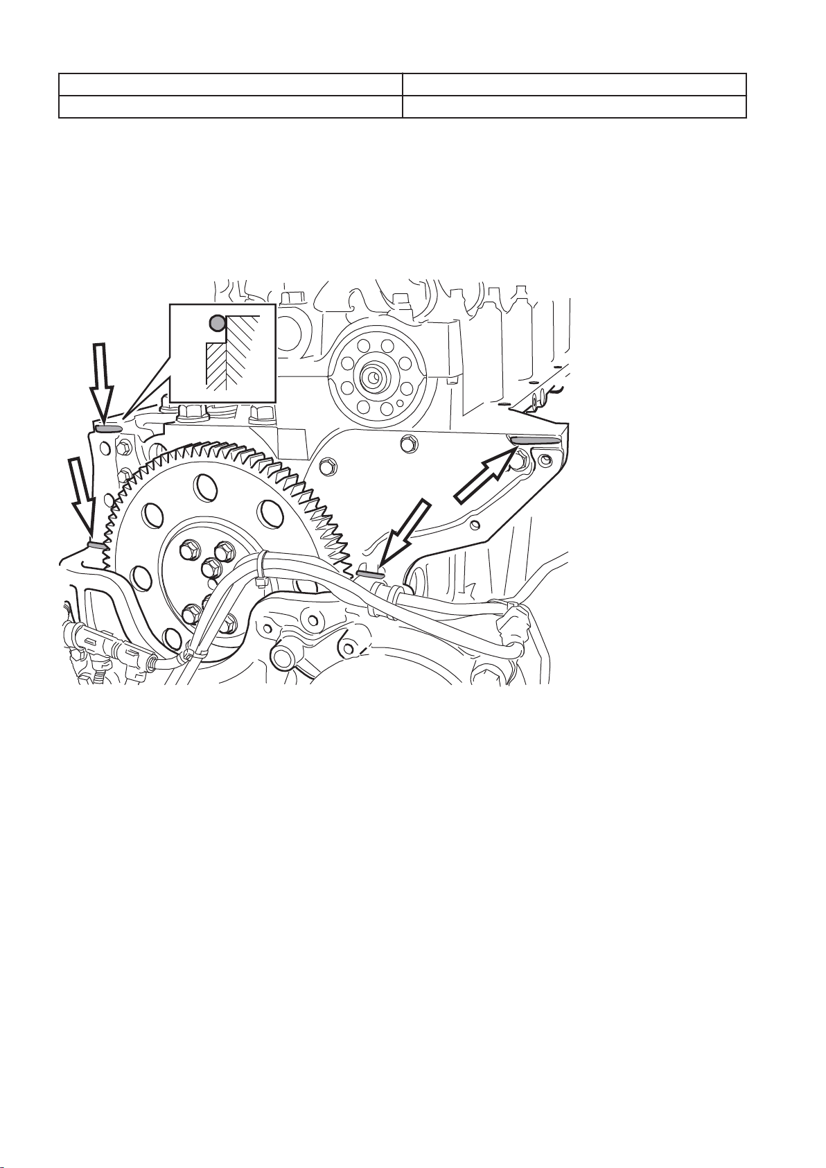
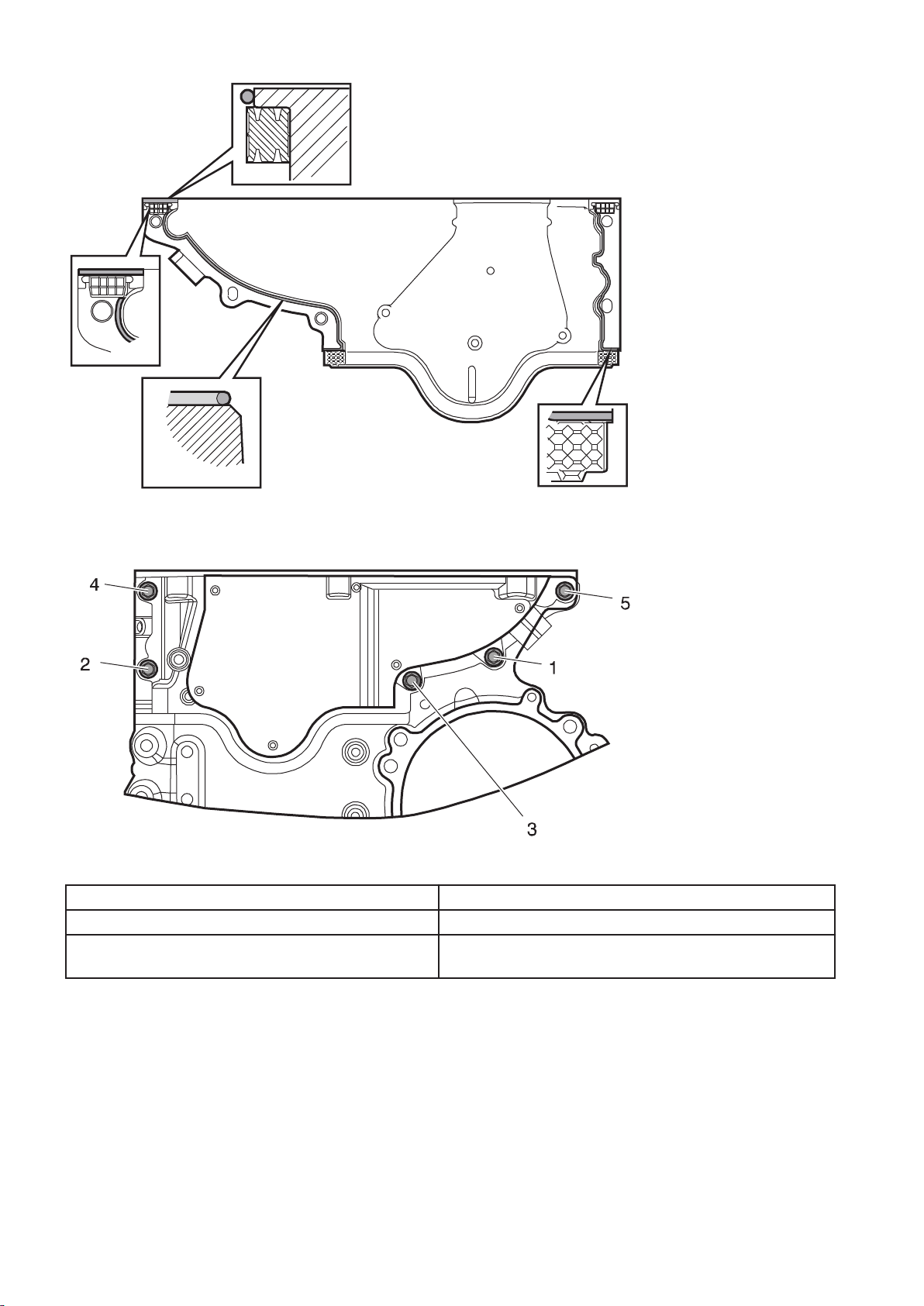
Timing gear casing
Apply a
2 mm (0.08 in) thick bead of sealant (part no. 11713514)
as shown in the figures on the timing gear casing's contact face
against the cylinder head. Install the rubber seals.
NOTE!
The timing gear casing must be installed and torque-tightened
within 20 minutes of applying the sealant.
Fig.3
9
Page 10
V1088411
Fig.4
V1088408
Fig.5 Tightening torques, upper timing gear casing
Timing gear casing (upper)
Step 1: Fasten the casing with the bolts 1 and 2. 4±1 Nm (3±0.74 lbf ft)
Tighten the bolts in the order shown in the above
24±4 Nm (18±3 lbf ft)
figure.
10
Page 11
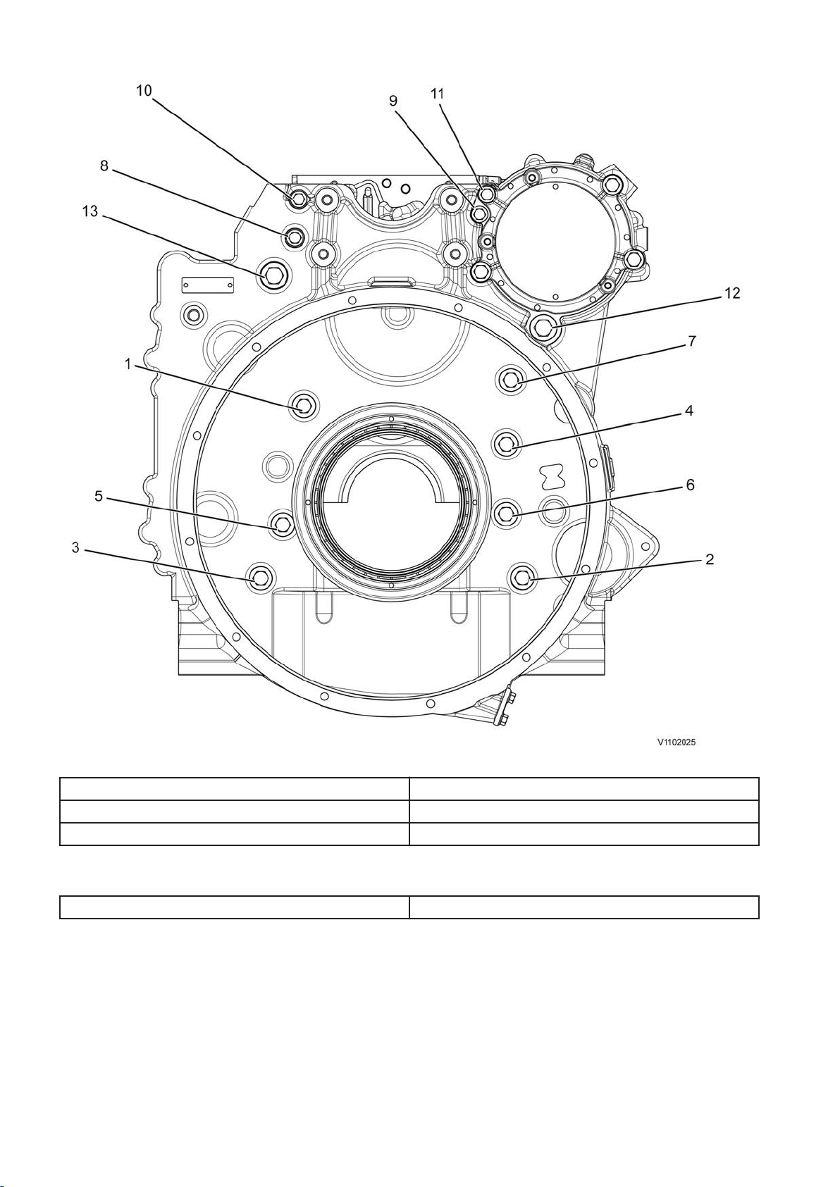
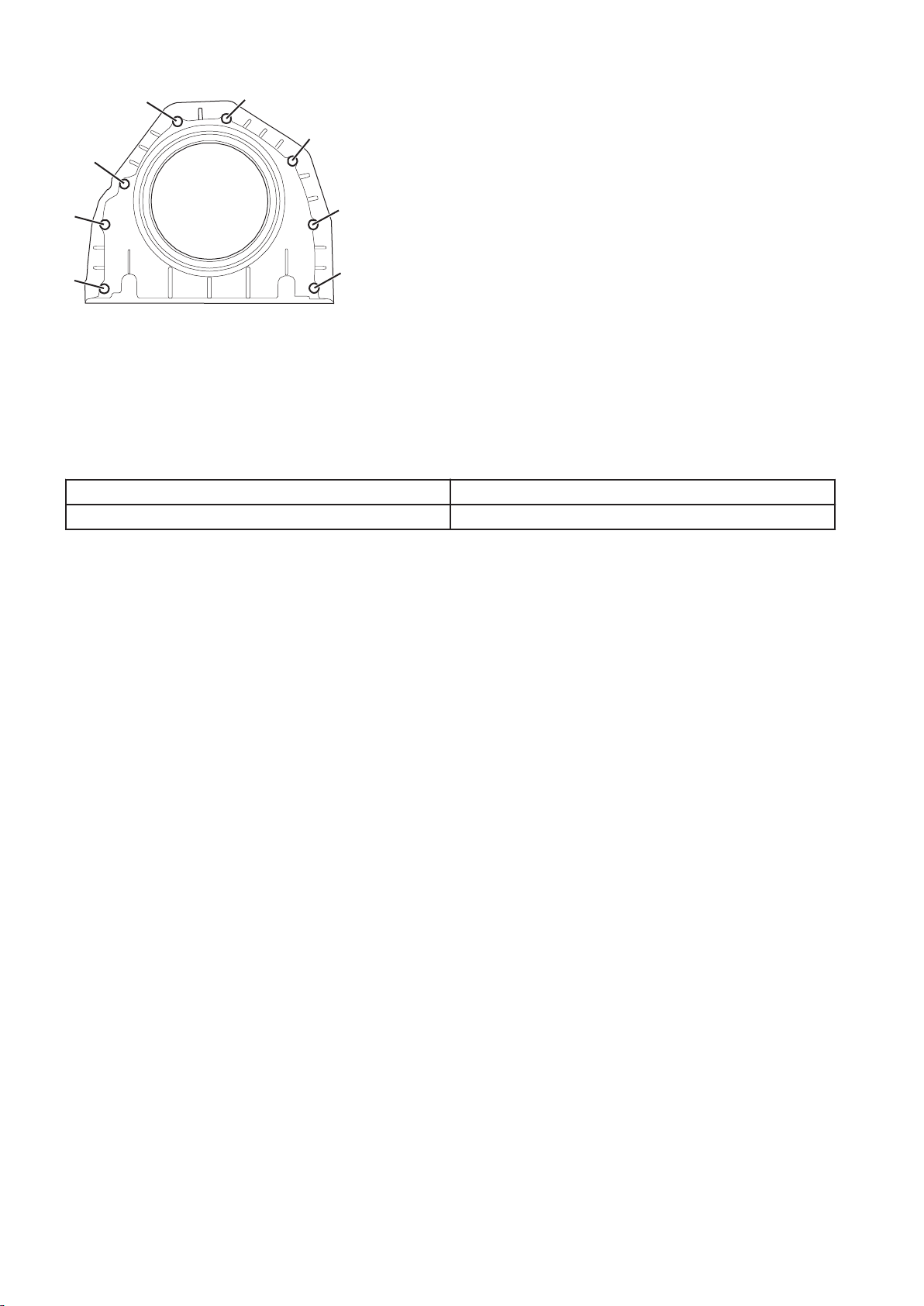
Tightening torques, flywheel housing WLO/EXC
Fig.6 Flywheel housing, WLO/EXC
M14-bolts 160 ± 10 Nm (118 ± 7.4 lbf ft)
M10-bolts 48 ±8 Nm (35.4 ±5.9 lbf ft)
M16-bolts 100±5 Nm (74±3.7 lbf ft)
Tightening torques, timing gear plate
M8-bolts 28±4 Nm (21±3 lbf ft)
11
Page 12
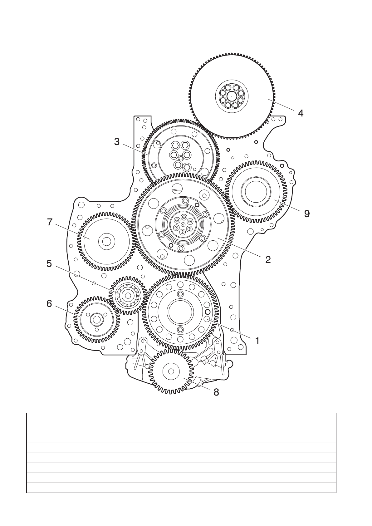
Engine transmission, specification
V1071840
Fig.7
Gears:
1. Drive gear, crankshaft
2. Transfer gears: outer and inner gear
3. Transfer gear (adjustable)
4. Drive gear and vibration damper, camshaft
5. Transfer gear
6. Drive gear, lubrication oil pump for fuel feed pump
7. Drive gear, compressor
12
Page 13
8. Drive gear, lubrication oil pump
V1082177
9. Not used
Gear flank clearance (backlash), adjustable transfer
0.05–0.15 mm (0.0019–0.0059 in)
gear to camshaft's drive gear
Gear flank clearance (backlash), oil pump's drive gear 0.05–0.41 mm (0.0019–0.016 in)
Gear flank clearance (backlash), other drive gears 0.05–0.20 mm (0.0019–0.0078 in)
For checking camshaft installation:
Valve lift, inlet valve, cylinder 1 at 6° after TDC 1.6 ± 0.3 mm (0.063 ± 0.012 in)
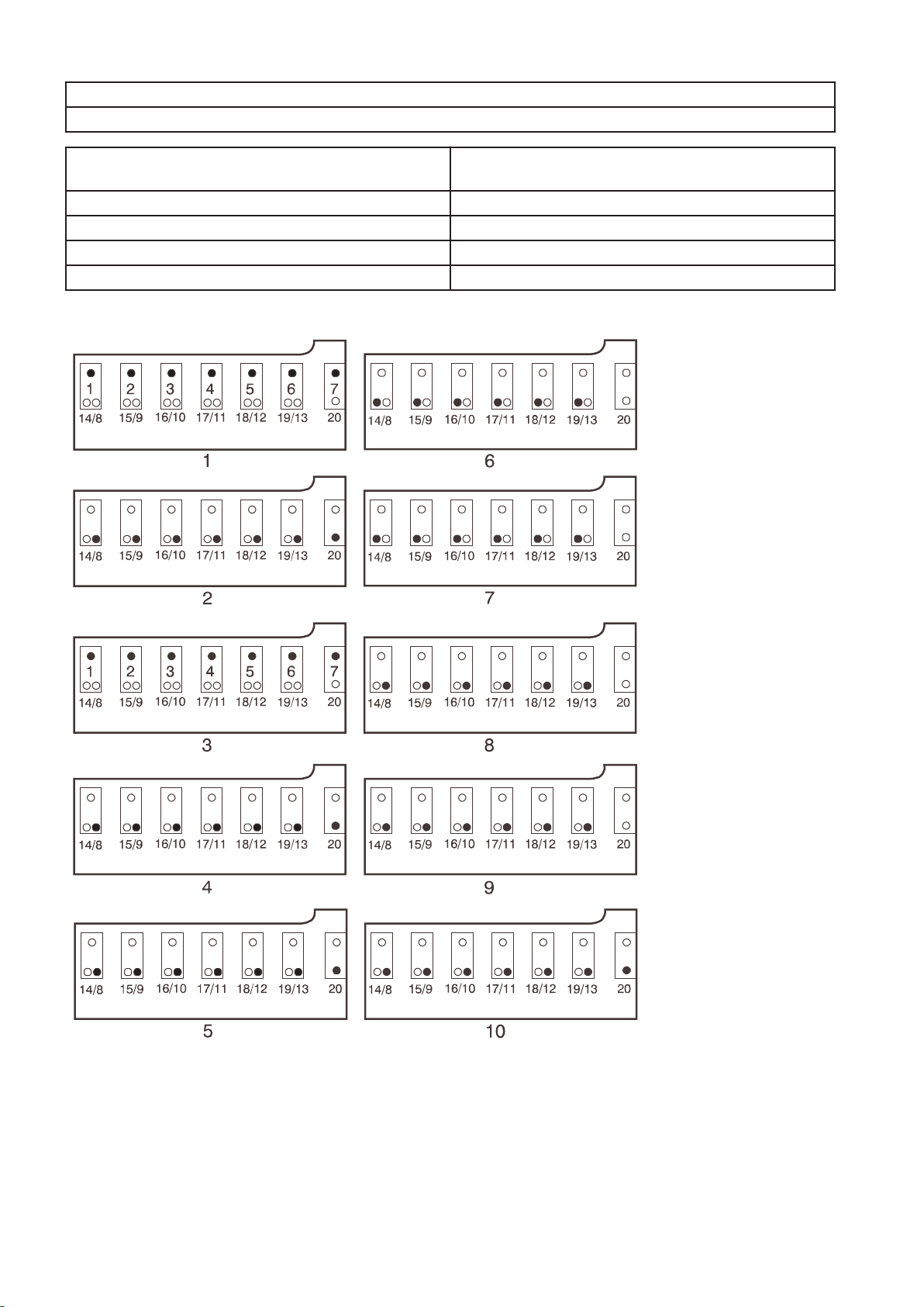
Rocker arm shaft, tightening torques
Fig.8
13
Page 14
Camshaft: (camshaft and bearing caps in place)
Fit a mandrel to the number 7 bearing bracket to protect the
guide sleeve.
Step 1: Tighten screws 1–7 25±3 Nm (18±2.2 lbf ft)
Step 2: (with shorter additional screws) Tighten screws 8–13 and
60±5 Nm (44±3.7 lbf ft)
20..... 60±5 Nm
Step 3: Angle tighten screws 1-7 90°±5°
Step 4: Remove the extra screws 8–13 and 20
Remove the mandrel from the number 7 bearing bracket.
Rocker arm shaft: (Rocker arm shaft in place)
Step 5: Tighten screws 8 - 13 and 20 in steps in the order 11,
60±5 Nm (44±3.7 lbf ft)
10, 12, 9, 13, 8, 20.
Step 6: Tighten screws 14–19 25±3 Nm (18±2.2 lbf ft)
Step 7: Angle tighten screws 14-19 120°±5°
Step 8: Untighten bolts 8–13
Step 9: Tighten screws 8-13 25±3 Nm (18±2.2 lbf ft)
Step 10: Angle tighten bolts 8 – 13 and 20 120°±5°
Valve mechanism, specifications
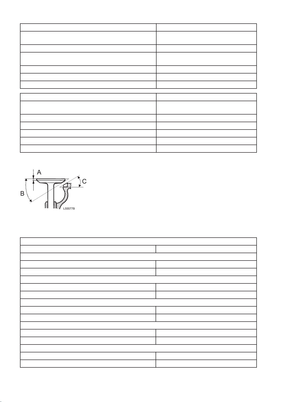
Fig.9
1 Valve disc, thickness (A)
2 Valve's seat angle (B)
3
Valve seat's angle (C)
Valves
Valve arrangement Top valves
Valve disc, diameter
Inlet 42 mm (1.65 in)
Exhaust 40 mm (1.57 in)
Valve stem, diameter
Inlet 7.968 mm (0.3137 in)
Exhaust 7.955 mm (0.3131 in)
Valve's seat angle
Inlet 24.5°
Exhaust 39.5°
Seat's angle in cylinder head
Inlet 25°
Exhaust 40°
Valve disc, thickness
Inlet 2.766 mm (0.108 in)
Exhaust 2.163 mm (0.085 in)
14
Page 15
Valve clearance, cold engine
Inlet valves, checking value 0.15 — 0.25 mm (0.0059 — 0.0098 in)
Inlet valves, setting value 0.20 mm (0.0079 in)
Exhaust valves, checking value 0.75 — 0.85 mm (0.029 — 0.033 in)
Exhaust valves, setting value 0.8 mm (0.031 in)
Brake rocker arm, checking value 2.78 – 2.92 mm (0.109 – 0.114 in)
Brake rocker arm, setting value 2.85 mm (0.112 in)
Checking value without feeler gauge on valve yoke Min. 3.20 mm (0.126 in)
Distance between valve disc and cylinder head's face:
Inlet
Max. 1.85 mm (0.072 in)
Min. 1.0 mm (0.039 in)
Exhaust
Max. 2.2 mm (0.086 in)
Min. 1.4 mm (0.055 in)
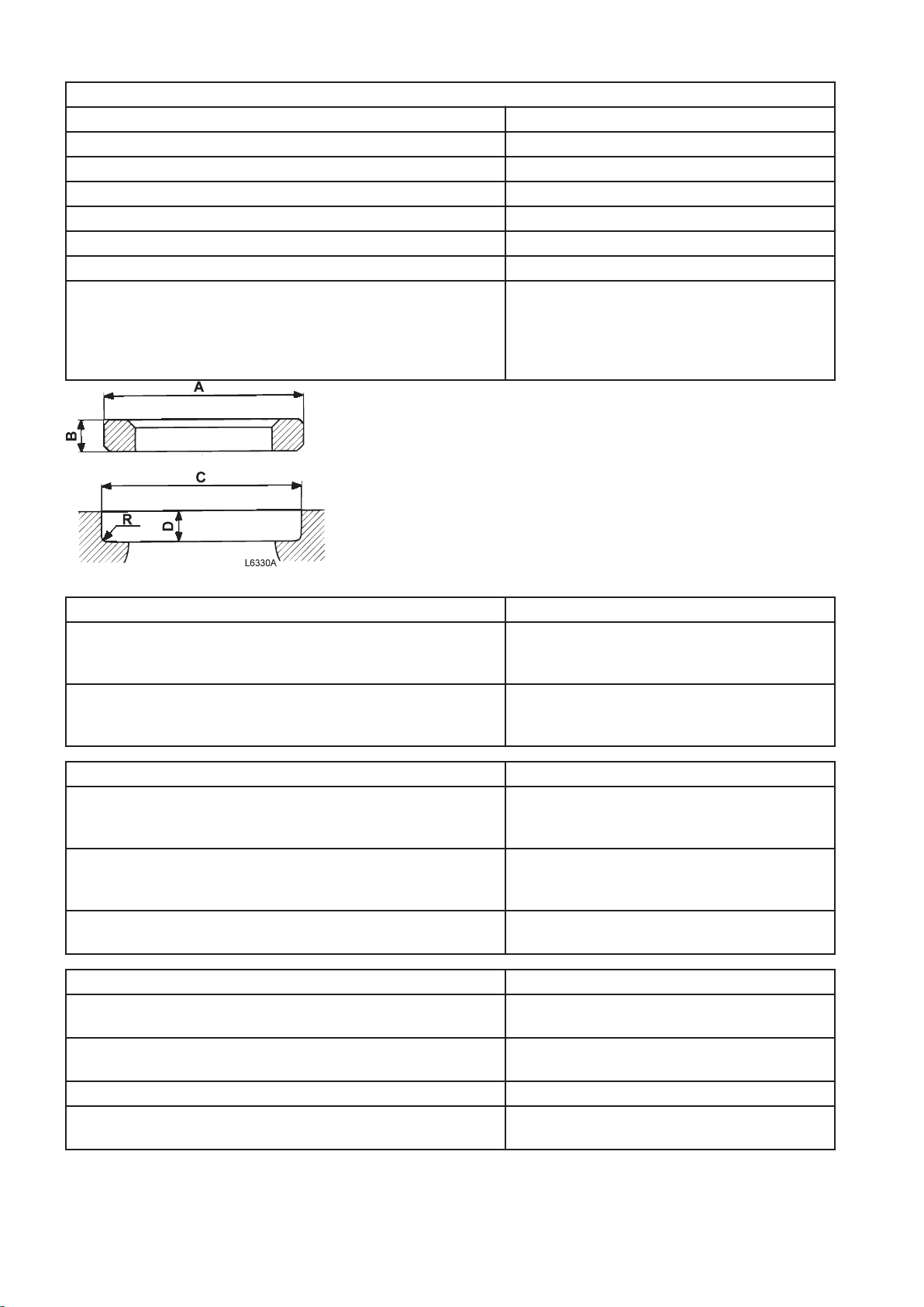
Fig.10 Valve seat and valve seat's position
Valve seats
Outside diameter (A) standard:
Inlet
Exhaust
Ø45 (+0.065+0.081) mm (1.78 in)
Ø43 (+0.07+0.086) mm (1.70 in)
Height (B):
Inlet
Exhaust
7.1 ±0.04 mm (0.279 ±0.0016 in)
7.25 ±0.025 mm (0.285 ±0.001 in)
Valve seat position
Diameter (C) standard:
Inlet
Exhaust
Ø45 H7 (0/+0.025) mm (1.77 in)
Ø43 H7 (0/+0.025) mm (1.69 in)
Depth (D):
Inlet
Exhaust
11.8 ±0.13 mm (0.46 ±0.005 in)
11.2 ±0.13 mm (0.44 ±0.005 in)
Seat's bottom radius (R):
Inlet/exhaust max. 0.8 mm (0.031 in)
Valve guides
Diameter:
Inlet/exhaust Ø8 0/+0.015 mm (0.31 in)
Height above cylinder head's spring face:
Inlet/exhaust 24.5 ±0.2 mm (0.96 ±0.008 in)
Wear value
Clearance, valve stem - guide
Inlet/exhaust max. 0.7 mm (0.028 in)
15
Page 16
Valve spring
10 1 15 1612 1113
14
6 2 38 79 4
5
19
20
18
17
V1083869
V1063169
16 15 14 13 17 6 71 8
12 11 10 9 18 3 42 5
Inlet
Length, unloaded 73.8 mm (2.90 in)
Exhaust
Outer valve spring:
Length, unloaded 73.8 mm (2.90 in)
Valve mechanism, tightening torques
Tightening torques
Lock nut, inlet valves 38 ± 4 Nm (28 ± 2.9 lbf ft)
Lock nut, floating valve bridge (exhaust) 38 ± 4 Nm (28 ± 2.9 lbf ft)
Lock nut, brake rocker arm 38 ± 4 Nm (28 ± 2.9 lbf ft)
Spring plate (tab) 25±3 Nm (18.5± 2.2 lbf ft)
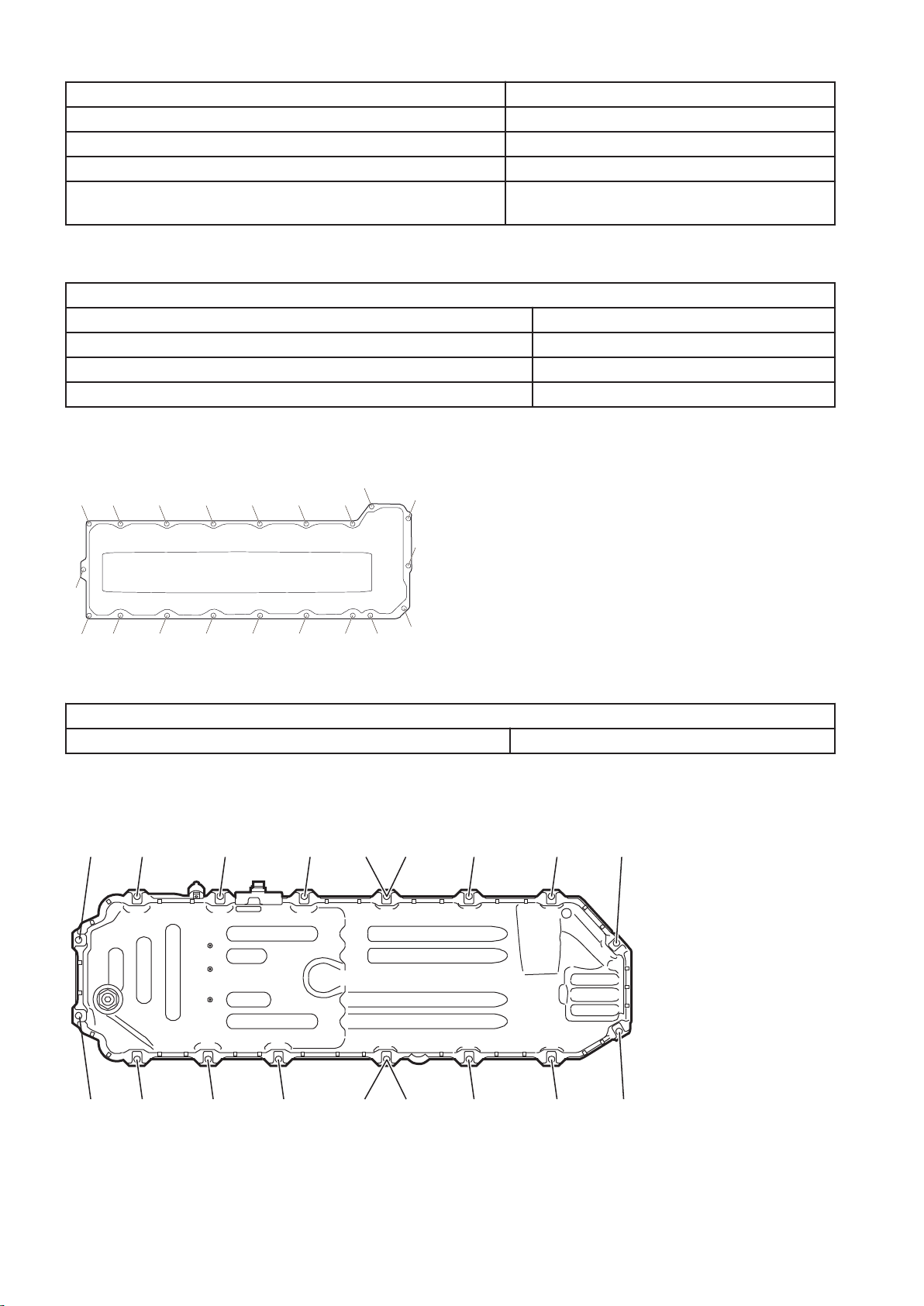
Tightening torques, valve cover
Fig.11 Figure 1 Tightening diagram, valve cover
Valve cover
Valve cover, screws 25 ± 3 Nm (18 ± 2 lbf ft)
Oil sump, tightening torque
Oil sump, tightening diagram
Fig.12 The illustration shows the oil sump for engine D13H, there may be some differences.
16
Page 17
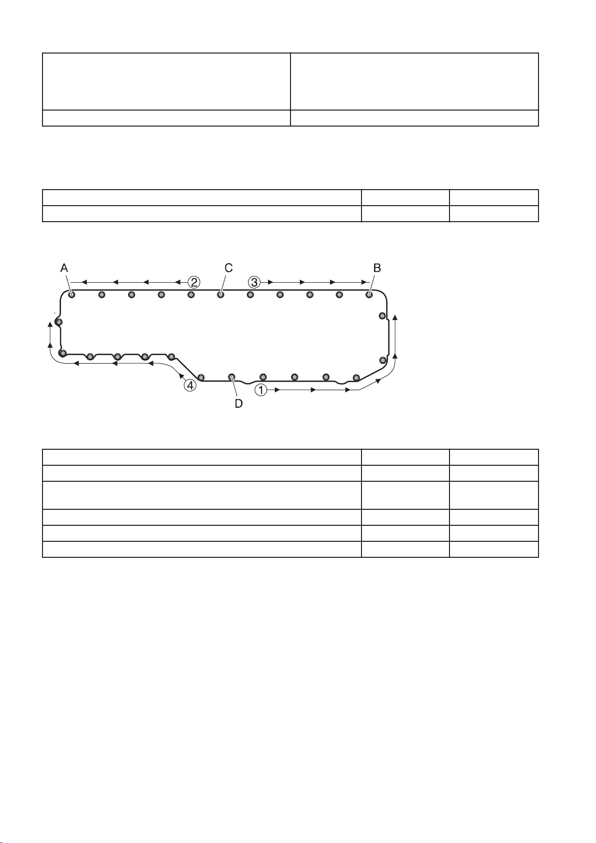
Oil sump
V1089423
NOTE!
Tighten the bolts in the numerical order shown in the
figure.
Drain plug, oil sump 52±8 Nm (38±6 lbf ft)
24±4 Nm (18±3 lbf ft)
Oil cooler, tightening torques
Oil cooler
Oil cooler, attaching bolts Nm lbf ft
Tighten the bolts crosswise 27 ±4 19,9 ±2,95
Oil cooler, cover
Fig.13
Oil cooler, cover: Nm lbf ft
Install the cover on the engine block and fit bolt A in the oval hole
Press the cover against the coolant pump housing with the special tool
and install bolt B
Install bolts C and D and tighten them 24 ±4 17.7 ±2.95
Tighten the cover's bolts in order, according to diagram 24 ±4 17.7 ±2.95
Finish by tightening bolts C and D again 24 ±4 17.7 ±2.95
17
Page 18
Cylinder block, tightening torques
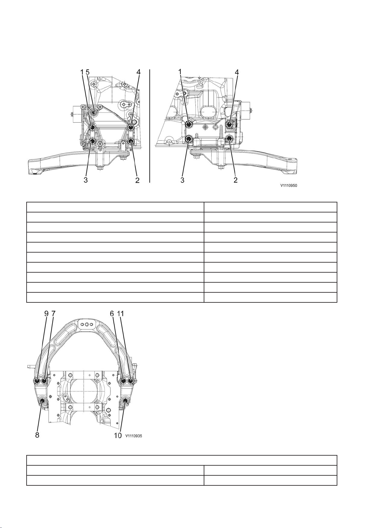
Engine mount incl. bracket
Fig.14 Front engine mount bracket
Front engine mount bracket, cylinder block:
Step 1: Tighten bolt 1. 80 ±15 Nm (59 ±11 lbf ft)
Step 2: Tighten bolts 2 — 4. 105±15 Nm (77.4±11 lbf ft)
Step 3: Angle-tighten bolts 2 — 4 in numerical order 60 ±5°
Step 4: Tighten bolt 1 105±15 Nm (77.4±11 lbf ft)
Step 5: Angle-tighten bolt 1 60 ±5°
Step 6: Tighten bolt 5 Standard bolt tightening torque
Front engine mount to frame 140±25 Nm (103.3±18.4 lbf ft)
Rear engine mount, flywheel housing:
EXC 262±26 Nm (193.2±19 lbf ft)
Fig.15 Front engine mount
Front engine mount to engine mount bracket
Step 1: Tighten bolts 6 – 11 5 ±2 Nm (3.7 ±1.5 lbf ft)
Step 1: Tighten bolts 6 – 11 275 ±45 Nm (203 ±33 lbf ft)
18
Page 19
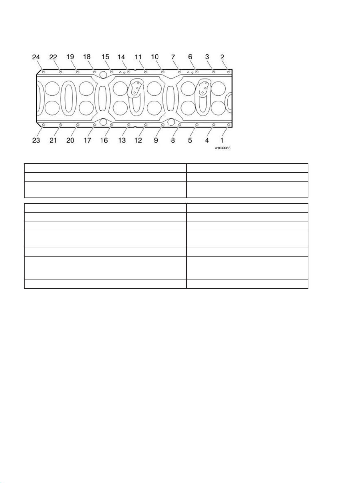
Ladder frame
Fig.16 Ladder frame
Ladder frame
Step 1: Tighten bolts 1 — 24 in numerical order 45±5 Nm (33.19±3.69 lbf ft)
Step 2: Tighten bolts in numerical order 1 — 24 (angletightening)
60 ±5°
Timing gear plate:
M8-bolts 28±4 Nm (20.7±2.95 lbf ft)
Main bearing caps:
Step 1
Step 2 (angle-tightening)
Connecting rod (big-end) caps:
Step 1
Step 2
Step 3 (angle-tightening)
Press tool for measuring liner height 40 Nm (29.5 ft lbf)
150±20 Nm (110.6±14.8 lbf ft)
120 ±5°
20±3 Nm (14.8±2.2 lbf ft)
60±3 Nm (44.3±2.2 lbf ft)
90 ±5°
Inlet
NOTE!
Tighten the bolts according to the numerical order in the figure.
The bolts shall not be reused.
19
Page 20
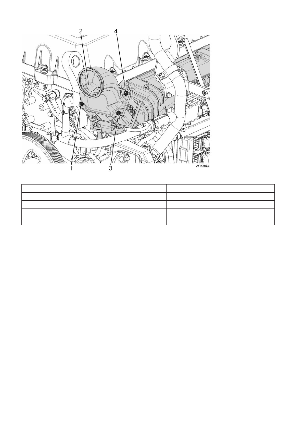
Fig.17 WLO, EXC: Mixing chamber, preheater
Inlet pipe
Mixing chamber, preheater:
Step 1 10±2 Nm (7.38±1.48 lbf ft)
Step 2 24±3 Nm (17.7±2.21 lbf ft)
Plug, M10 (inlet pipe) 20±3 Nm (14.8±2.2 lbf ft)
NOTE!
Torque-tighten the bolts diagonally as shown in the figure.
20
Page 21
Tightening torque, fuel system
1
3 5 7 9
11
12
108
2
4
6
V1100866
Bolt, fastener yoke, unit injectors. Copper sleeve Steel sleeve
step 1 25 +5/-0 Nm (18.4 +3.7/-0 lbf ft) 20 Nm +5/-0 (14.8 +3.7/-0 lbf ft)
step 2 90° ±5° 90° ±5°
New sleeve or new cylinder head
Bolt, fastener yoke, unit injectors Copper sleeve Steel sleeve
step 1 30 +5/-0 Nm (22 +3.7/-0 lbf ft) 20 +5/-0 Nm (14.8 +3.7/-0 lbf ft)
step 2 150° ±5° 180° ±5°
Step 3: Loose the yoke's bolt until the torqueis10–15 Nm (7.4–11 lbf ft) 10–15 Nm (7.4–11 lbf ft)
step 4 25 +5/-0 Nm (18.4 +3.7/-0 lbf ft) 20 +5/-0 Nm (14.8 +3.7/-0 lbf ft)
step 5 90° ±5° 90° ±5°
Lock nut for adjusting screw, unit injectors 52 ±4 Nm (38.4 ±lbf ft)
Banjo screw, fuel hose
M10 18 ±3 Nm (13.3 ±2.2 lbf ft)
M12 26 ±4 Nm (19.2 ±2.9 lbf ft)
M14 38 ±6 Nm (28 ±4.4 lbf ft)
M16 48 ±8 Nm (35.4 ±6 lbf ft)
Fuel pump (mounted on oil pump) 8 +2/–0 Nm (5.9 +1.5/-0 lbf ft)
Oil pump 24 ±2 Nm (17.7 ±1.5 lbf ft)
Unit injectors, preload Tighten the adjusting screw to zero clearance against the camshaft,
then turn it 240° ±20°
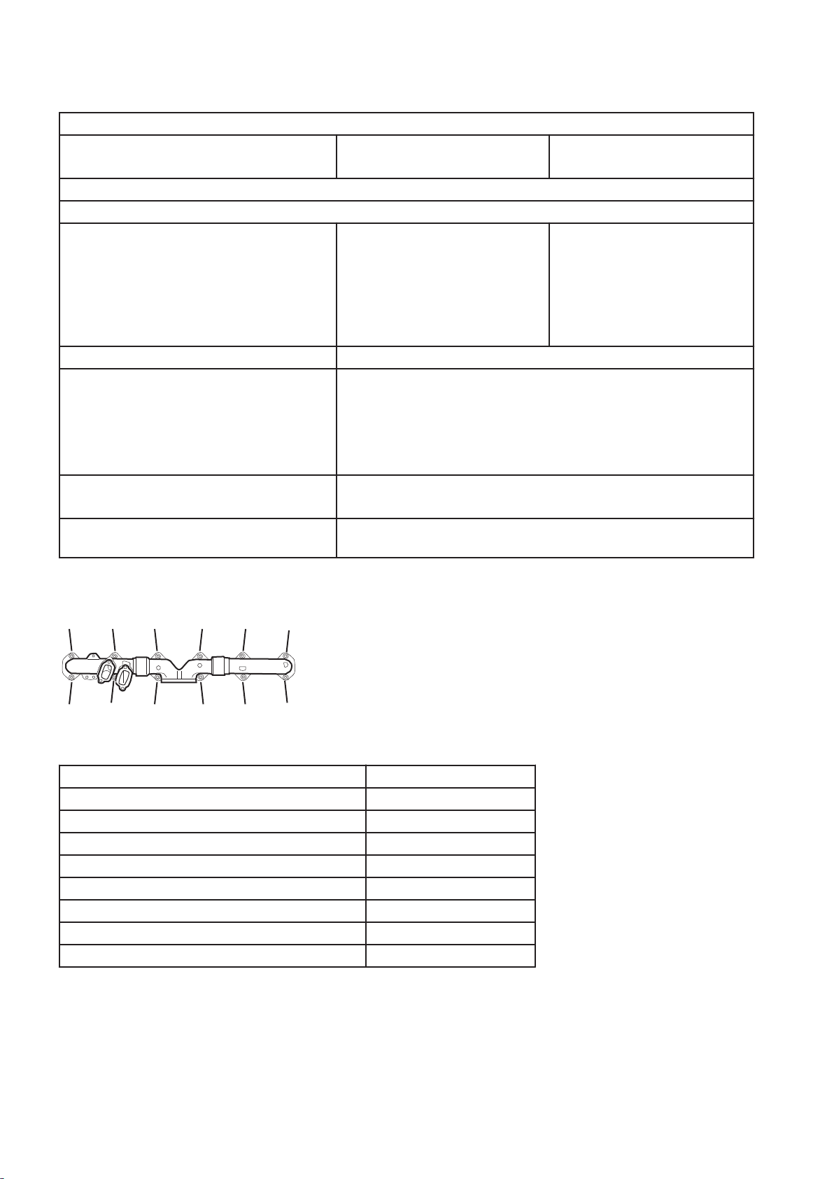
Exhaust manifold, tightening torques
Fig.18
Step 1:
Tighten bolts 1, 4, and 5, 8, and 9, 12 to contact 10±1.5 Nm (7.4±1.1 lbf ft)
Step 2:
Tighten bolts 3 and 2 48±8 Nm (35.4±5.9 lbf ft)
Tighten bolts 7 and 6 48±8 Nm (35.4±5.9 lbf ft)
Tighten bolts 11 and 10 48±8 Nm (35.4±5.9 lbf ft)
Tighten bolts 1 and 4 48±8 Nm (35.4±5.9 lbf ft)
Tighten bolts 5 and 8 48±8 Nm (35.4±5.9 lbf ft)
Tighten bolts 9 and 12. 48±8 Nm (35.4±5.9 lbf ft)
Turbocharger, tightening torques
21
Page 22
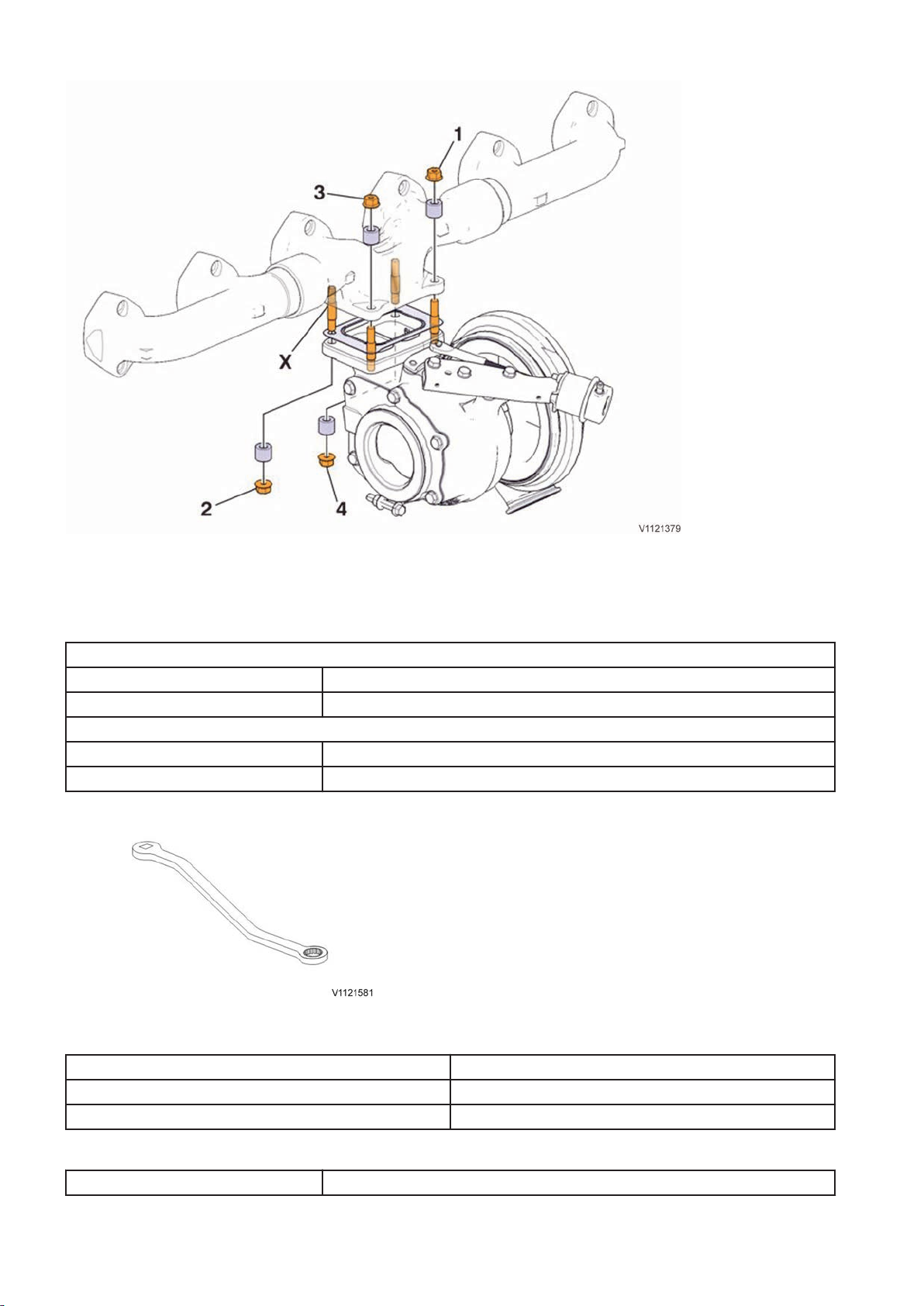
Fig.19 Bolts for installing the turbocharger to the exhaust manifold.
NOTE!
Torque-tighten bolts diagonally as shown in the figure.
Table. Against exhaust manifold
Position 1 and 3
step 1 20 ±4 Nm (14.8 ±3 lbf ft)
step 2 48 ±8 Nm (35.4 ±6 lbf ft)
Position 2 and 4 — using the tool 88830179 Wrench
step 1 16,8 Nm (12.2 lbf ft)
step 2 40,2 Nm (29.6 lbf ft)
Fig.20 88830179 Wrench, for position 2 and 4
Table. Connections for coolant and lubrication oil
Tightening torques, turbo
Coolant lines 38±6 Nm (28±4.4 lbf ft)
Oil lines 48±5 Nm (35.5±3.7 lbf ft)
Table. Charge-air cooler pipe
Clamps 8,5±0,8 Nm (6.3±0.6 lbf ft)
22
Page 23
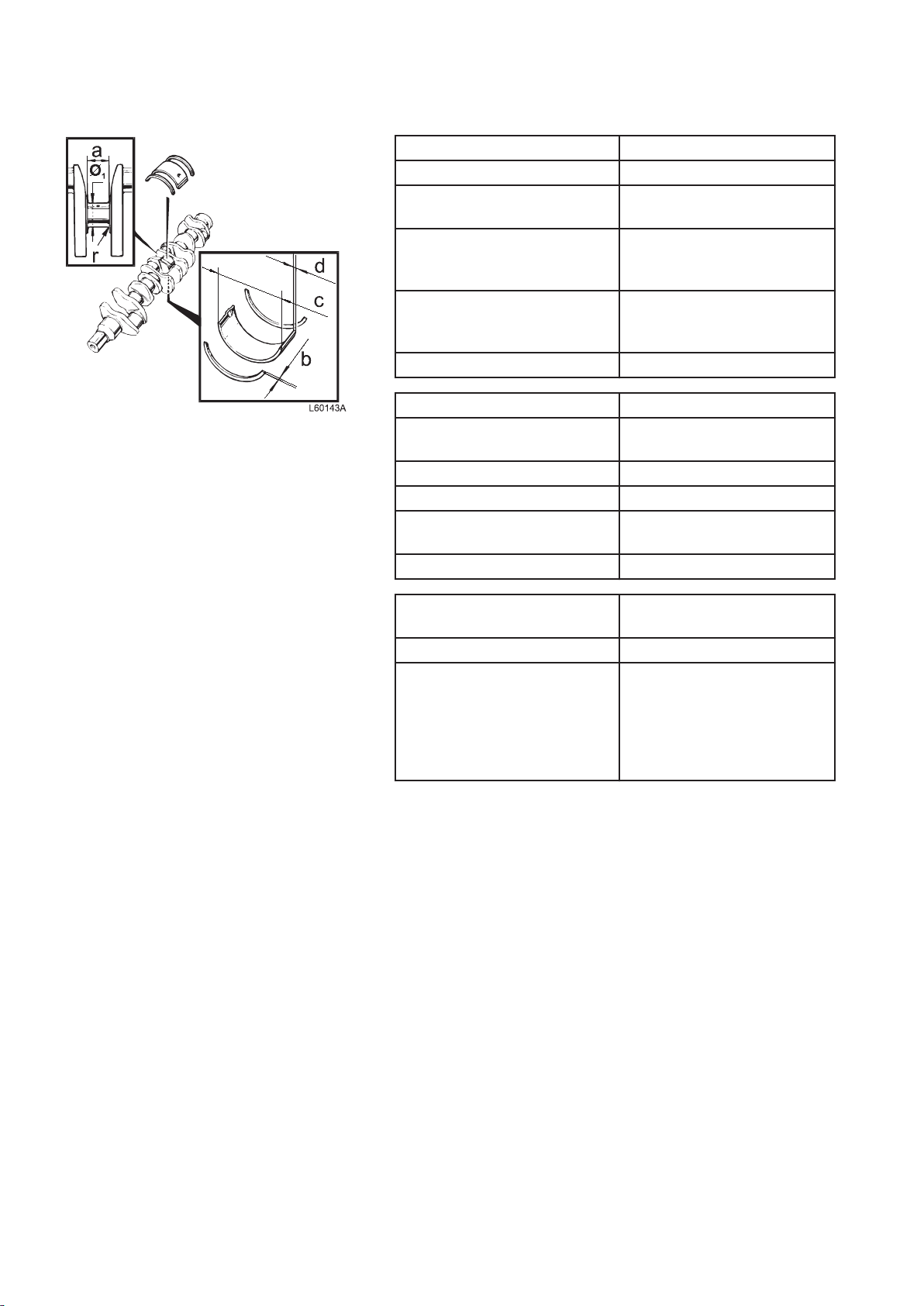
Fig.21
Crank mechanism, specifications
Crankshaft
Length 1 153.8 mm (45.4 in)
Crankshaft, max. axial
clearance
Max. permitted ovality of main
bearing and big-end bearing
pins
Max. permitted conicity of main
bearing and big-end bearing
pins
Max. run-out of middle bearing 0.15 mm (0.0059 in)
Main bearing pin
Diameter (Ø) for reworking,
standard
surface finish, main bearing pin Ra 0.25 mm (0.00098 in)
surface finish, radius Ra 0.4 mm (0.00044 in)
Width, thrust bearing pin (a),
standard
Fillet radius (r) 4.0 mm (0.157 in)
0.4 mm (0.016 in)
0.006 mm (0.00024 in)
< 0.02 mm (< 0.0008 in)
108.0 mm (4.25 in)
47.0 mm (1.85 in)
Thrust washers (thrust
bearings)
Width (b), standard 3.18 mm (0.125 in)
Oversize:
0.1 mm (0.0039 in) 3.28 mm (0.129 in)
0.2 mm (0.0079 in) 3.38 mm (0.133 in)
0.3 mm (0.0118 in) 3.48 mm (0.137 in)
0.4 mm (0.0157 in) 3.58 mm (0.141 in)
23
Page 24
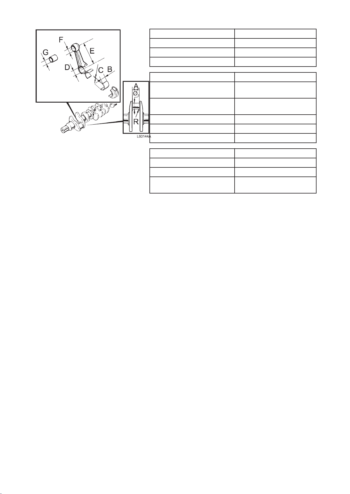
Fig.22
Main bearing shells
Type Replaceable
Outer diameter (c) 113.065 mm (4.451 in)
Thickness (d), standard 2.485 mm (0.098 in)
Crankshaft bearing pins
Diameter (Ø) for reworking,
99 mm (3.897 in)
standard
Surface finish, crankshaft
Ra 0.25
bearing pin
Surface finish, radius Ra 0.4
Width (A) 57 mm (2.244 in)
Fillet radius (r) 4.0 mm (0.157 in)
Connecting rods' bearing shells
Outer diameter (B) 103.85 mm (4.088 in)
Thickness (C), standard 2.389 mm (0.094 in)
Diameter, bearing shell's
103.835 mm (4.088 in)
bearing seat (D)
24
Page 25
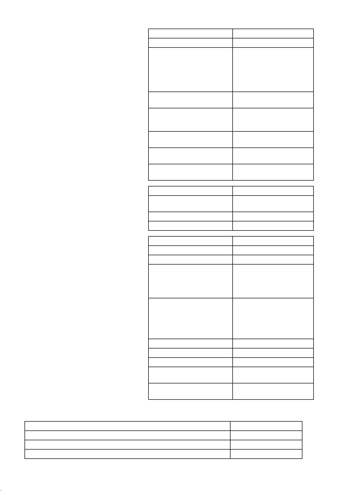
Connecting rod
Length, centre – centre (E) 267.5 mm (10.53 in)
Marking:
"FRONT" on
to face the front.
Connecting rods and caps are
pair-marked with a three-digit
running number.
Connecting rod bushing's
internal diameter (G)
Axial clearance, connecting rod
– crankshaft, with marking
directly opposite each other
Big-end bearing, radial
clearance, oiled part
Straightness (max.) deviation
per 100 mm measured length
Twisting (max.) deviation per
100 mm measured length
Piston
Height above cylinder block
face
Number of ring grooves 3
Front marking Arrow facing forward
rod shall be turned
58 mm (2.283 in)
< 0.35 mm (<0.014 in)
< 0.10 mm (0.0039 in)
0.06 mm (0.0024 in)
0.15 mm (0.0059 in)
0.15–0.21 mm (0.006– 0.008
in)
Piston rings
Compression rings
Quantity 2
Piston ring clearance in groove:
upper compression ring Trapezius-shaped profile
lower compression ring 0.09–0.14 mm (0.003– 0.005
in)
Piston ring gap in ring opening:
upper compression ring 0.40–0.55 mm (0.0157–
0.0216 in)
lower compression ring 1.30–1.50 mm (0.051– 0.059
in)
Oil scraper ring
Quantity 1
Width incl. spring 3.41 mm (0.134 in)
Piston ring clearance in groove 0.05–0.10 mm (0.019– 0.039
in)
Piston ring gap in ring opening 0.30–0.55 mm (0.011– 0.021
in)
Crankshaft, tightening torques
Cover, crankshaft seal
Step 1: Fasten the cover with the bolts 2 and 7 and tighten to contact.
Step 2: Tighten bolts 2 and 7 24±4 Nm (17.7±2.95 lbf ft)
Step 3: Tighten the bolts in numerical order 1, 3 — 6, 8 as shown in the figure. 24±4 Nm (17.7±2.95 lbf ft)
25
Page 26
V1048013
1
2
3
4
5
6
7
8
Fig.23
Flywheel, tightening torques
NOTE!
The bolts
Tighten the bolts in the order shown in the following figure. All
bolts are tightened in two steps:
Step 1 60±5 Nm (44±3.7 lbf ft)
Step 2, angle-tightening 120°±10°
may only be reused twice, then new bolts shall be used.
26
Page 27

Fig.24 Flywheel
Belt pulley/vibration damper, tightening torques
Fig.25 Belt pullet/vibration damper
Vibration damper and belt pulley
Step 1, according to numerical order in figure: 35±5 Nm (25.8±3.7 lbf ft)
Step 2, according to numerical order in figure: 90±10 Nm (66.4±7.4 lbf ft)
27
Page 28

ENGINE WITH MOUNTING AND EQUIPMENT
21 ENGINE
210 General, common info about 211 218
Engine, mounting in work stand
Op. no. 210-081
Tools:
9986485 Support
88800345 Fixture
88800123 Fixture
Lifting eye, 2 pcs.
Sling 3 m (118 in)
Ratchet block 1,500 kg (3307 lbs)
NOTE!
Since the engine illustrations in the service publications are
reused for different engine versions, some parts may vary from
the version
illustrations is always correct.
in question. However, the essential information in the
Engine D13F, weight:
WLO approx. 1,330 kg (3,932 lbs)
EXC approx. 1,330 kg (3,932 lbs)
1 Unplug the sensors and the cable harness. Unplug the
connectors from the E-ECU. Remove the cable channel.
28
Page 29
V1044013
1
2
3
4
5
6
7
8
10
11
9
Fig.26 Sensor, control system
1 Sensor for coolant level, SE2603
Sensor for coolant temperature, SE2606
2
3 E-ECU
4 Cable channel
5 Camshaft sensor, engine position, SE2703
6 Sensor for boost pressure/charge-air temperature, SE2507/SE2508
7 Sensor for air pressure/air temperature, SE2501/SE2502
8 Speed (rpm) sensor, flywheel, SE2701
9 Sensor for oil pressure, SE2203
10 Sensor for oil level/oil temperature, SE2205/SE2202
11 Sensor for crankcase pressure, SE2509
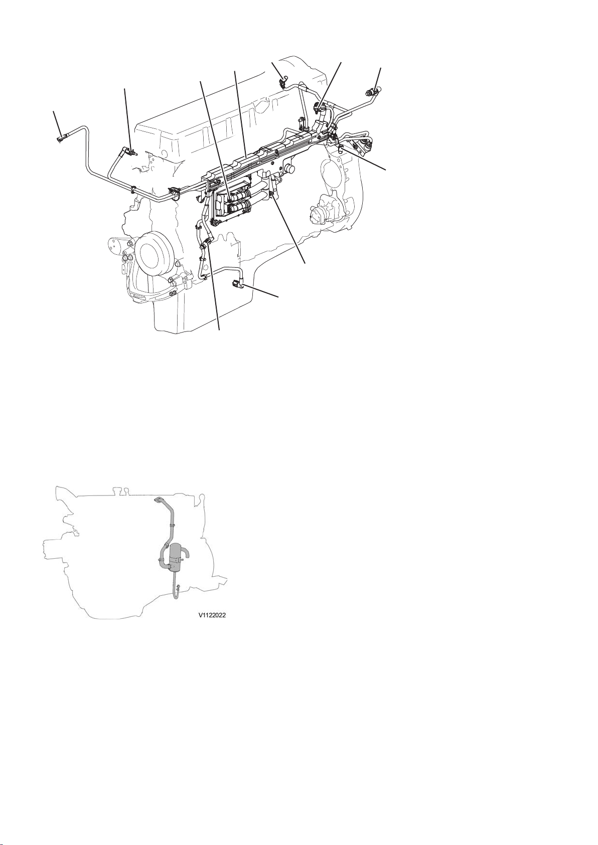
2 Disconnect the oil trap hose from the oil sump. Disconnect
the oil trap pipe from the valve cover. Remove the oil trap,
pipe and hose.
Fig.27 Oil trap with hose and pipe
NOTE!
Collet the waste oil in a suitable container.
29
Page 30

1
2
3
V1045797
Fig.28 Fuel lines
V1111475
1
2
1 Cooling circuit, E-ECU
2 Bracket — different location for EXC
Fuel pump
3
3 Disconnect the fuel lines from the cylinder block, E-ECU,
cylinder head, and the fuel pump. Remove the bracket (for
the fuel connections, also know as fuel interface).
4 Remove the E-ECU.
Install 88800123 Fixture and 88800345 Fixture and tighten
5
with torque.
Fig.29
1 88800345 Fixture
2 88800123 Fixture
Fig.30
1 Ratchet block
2 Sling
6 Install the ratchet block and sling on the engine and connect
the engine to the lifting device.
Install the engine in 9986485 Support.
30
Page 31

Secure the engine by placing three axle stands under the
engine.
NOTE!
If the engine is heavier than the stand's weight-bearing
classification the engine must rest on three axle stands that are
placed under the engine before the lifting device is removed.
31
Page 32

Engine, dismantling
Op. no. 210-077
Tools:
11666054 Jack
88830175 Pump
9990114 Puller
88800352 Lifting tool
9990262 Adapter
9992955 Puller plate
9993590 Gear wheel
9993717 Quick nut
9993717 Quick nut
9993722 Support
9993791 Puller bolt
9996400 Impact puller
9998267 Guide
88830179 Wrench
Sling 1 m (39 in)
Feeler gauge
NOTE!
Since the engine illustrations in the service publications are
reused for different engine versions, some parts may vary from
the version
illustrations is always correct.
in question. However, the essential information in the
This operation also includes tools and times necessary for
applicable parts of the following actions:
Cylinder head, removing page 59
-
-
Valves, adjusting page 88
32
Page 33

Fig.31
1 Bolts connecting the turbo with the exhaust
manifold
2 Coolant line for turbo cooling
Coolant line
3
4 Oil pressure hose
5 Oil return hose
6 Charge-air cooler pipe
7 Clamp for charge-air cooler
1 - Remove the
clamps and hose for the charge-air cooler.
- Remove the charge-air cooler pipe.
- Remove the coolant lines for turbo cooling.
- Loosen the end of the oil pressure and return hoses at
the turbocharger.
- Loosen the rear bolts for the turbocharger.
- Connect a lifting device to the turbocharger.
- Drain the oil.
- Remove the front bolts and remove the turbocharger
with the lifting device. For WLO — remove the
turbocharger including the waste gate.
- Remove the rear bolts for the turbocharger and the
gasket.
- Remove the oil hoses.
Turbo, weight: approx. 28 kg
NOTE!
Collect the waste oil in a suitable container.
2 Remove the exhaust manifold.
3 Remove the coolant pipe between the cylinder head and the
coolant pump.
4 - Remove the lower bolt for the oil filler pipe.
- Remove the oil filler pipe.
- Remove the oil dipstick.
- Remove the inlet manifold with the preheating coil.
Fig.32 Oil filler pipe, oil dipstick, inlet manifold with
preheating coil.
5 Remove the lift plate.
6 Remove the valve cover.
33
Page 34

7 - Remove the upper timing gear casing.
- Remove the vibration damper and the camshaft gear.
Fig.33
1 Upper timing gear casing
2 Vibration damper
Camshaft gear
3
Remove the cylinder head according to
8
removing page 59
.
Cylinder head,
9 Remove the oil filters and the pipes for the oil filters. — only
WLO
NOTE!
Collect the waste oil in a suitable container.
10 - For EXC — remove the fan hub. For WLO — Remove
the upper belt pulley.
- Remove the lower belt pulley.
- Remove the tensioner pulleys.
- Remove the vibration damper.
11 Remove the coolant pump.
Fig.34
1 Coolant pump
2 EXC: Fan hub / WLO: Upper belt pulley
3
Tensioner pulleys
4 Vibration damper
5 Lower belt pulley
34
Page 35

Fig.35
1 Bracket for AC compressor and alternator
2 Bracket with belt tensioner
Bracket for belt tensioners
3
4 Front engine mount
12 - Remove the front engine mount.
- Remove the belt tensioners, idlers and brackets.
Remove the filter housing and the pipes.
13
Fig.36
1 Pipe
2 Filter housing
Fig.37 Fuel pump
14 Remove the fuel pump.
15 Disconnect the lubrication oil lines from the oil sump.
16 Remove the oil sump.
17 Install 9993590 Gear wheel in the flywheel housing to
prevent the crankshaft from rotating.
18 Loosen the bolts for the flywheel (12 pcs.).
35
Page 36

Fig.38
1 Sling 1 metre
2 M10 Lifting eye
19 Remove the flywheel.
Weight:
WLO approx. 40 kg (88 lbs)
EXC approx. 75 kg (165 lbs)
20 Install lifting eyes on the flywheel housing and secure it.
Loosen the bolts on the flywheel housing and then lift away
21
the flywheel housing.
Flywheel housing, weight: approx. 200 kg (441 lbs)
22 Rotate the engine 180°.
23 - Remove the strainer and the pipes for the lubrication
oil pump.
- Remove the ladder frame.
24 Rotate back the engine 180°.
Fig.39
1 Ladder frame
2 Pipes for lubrication oil pump
3
Strainer
Fig.40
1 Oil cooler
25 Remove the oil cooler.
26 Rotate the engine 180°.
27 Remove the casing with the front crankshaft seal.
28 Remove the lubrication oil pump.
29 Remove the transfer gear for the fuel pump.
30 Loosen and remove the bolts that hold the double gear (6
pcs.). Remove the double gear.
Fig.41
36
Page 37

Fig.42
1 Internal puller
31 - Remove the rest of the bolts for the crankshaft gear.
- Install an internal puller as shown in the figure.
Pull out and remove the gear.
-
32 - Install 9998267 Guide (2 pcs.) and remove the bracket
and bolts (23 pcs.) that hold the timing gear plate.
- Carefully remove the timing gear plate.
Fig.43
1 9998267 Guide.
2 Bracket
Fig.44
1 Piston cooling nozzle
33 Remove the piston cooling nozzles.
37
Page 38

V1022057
Fig.45
34 - Remove the bolts (4 pcs.), the caps, and carefully tap
loose the piston and connecting rod.
NOTE!
Avoid striking
on the connecting rod's mating surfaces.
- Repeat for the rest of the pistons and connecting rods.
35 - Remove the bolt and remove the main bearing cap.
- Repeat for the rest of the main bearing caps. Note
position of the main bearing caps for reinstalling later
on.
NOTE!
Save and keep track of the thrust bearings located on
the 4th cylinder's main bearing.
Fig.46
1 9996400 Impact puller, 9990114 Puller and
9990262 Adapter
Fig.47
36 Turn the crankshaft so that the 1st cylinder's and 6th
cylinder's bellcranks are positioned straight up. Secure with
lift slings in the lifting device and lift away the shaft.
Crankshaft, weight: approx. 125 kg (275 lbs).
Remove the main bearings.
38
Page 39

Fig.48
1 9993791 Puller bolt
2 9993717 Quick nut
11666054 Jack
3
4 88830175 Pump
5 9993722 Support (Use the long support legs)
6 9992955 Puller plate and 9993717 Quick nut
Cylinder liners, removing
37 Mark the position of the liners in the cylinder block and pull
out the cylinder liners with the tools shown in the figure.
Remove the old seals.
38
NOTE!
Work carefully so that the block is not damaged.
Thoroughly clean the grooves for the seals and the cylinder
liner's sealing faces against the cylinder block. Thoroughly
clean the sealing face on the liner shelf from rust, grease,
and deposits.
NOTE!
Do not use any scraper tools made of metal.
39 Check the rest of the engine block's seals, connections,
channels, etc. Clean, and replace any damaged parts.
39
Page 40

Engine, assembling
Op. no. 210-078
Tools:
885812 Timing tool
88800021 Installation tool
88800031 Setting tool
88800123 Fixture
88800318 Piston ring compressor
88800345 Fixture
88830179 Wrench
88880003 Bracket
9812524 Milling tool
88800352 Lifting tool
9990166 Installation tool
9992000 Handle
9992479 Retainer
9992663 Sealing plate
9992955 Puller plate
9993590 Gear wheel
9996662 Pressure gauge
9996684 Sealing plate
9996966 Press tool
9996966 Press tool
9996966 Press tool
9996966 Press tool
9996966 Press tool
9996966 Press tool
9996966 Press tool
9998143 Sealing plate
9998238 Drift
9998267 Guide
9998267 Guide
9998288 Sealing plate
9998318 Press tool
9998601 Installation tool
Sealant 1161231
Feeler gauge
Sling 1 m (39 in)
Sling 3 m (118 in)
Lifting eye 2 pcs.
Lifting eye M10, 2 pcs.
Dial indicator with magnetic stand
This operation also includes tools and times necessary for
applicable parts of the following actions:
Cylinder block, liners removed, milling of all liner
-
locations page 82
-
Cylinder head, fitting page 76
-
Oil cooler, leakage check page 91
-
Engine, removing from work stand page 56
40
Page 41

V1094730
Fig.49
Fig.50
1 9992479 Retainer
2 Dial indicator
Cylinder liners, installing
1 Check the cylinder block's liner shelves for any damage.
If the liner shelf is damaged it must be overhauled. See
Cylinder block, liners removed, milling of all liner
locations page 82
.
Install the cylinder liners without O-rings and fixate them with
9996966 Press tool.
Tightening torque press tools, see
torques page 18
.
Cylinder block, tightening
2 Install a dial indicator in 9992479 Retainer. Place the holder
with the dial indicator across the cylinder liner. Reset the dial
indicator to zero with a couple of millimetres preload against
the cylinder block's face.
3 Measure the height between the cylinder liner and the
cylinder block's face. Measure the liner's height at two
different points diagonally opposite to each other.
NOTE!
The sealing face is convex. Always measure at the highest
point on the sealing face.
Calculate the average value of both measurements.
For correct liner height over the block face, see
block, specifications page 7
.
Cylinder
If the liner's height over the block face is higher than the
stated tolerance, then the liner shelf in the cylinder block has
to be milled. Milling should take place at an authorized
workshop.
See
Cylinder block, liners removed, milling of all liner
locations page 82
.
Mark the liner's position in the cylinder block with a magic
marker, so that it ends up in the same position when
installing. Repeat the procedure for the rest of the cylinder
liners.
Fig.51
1 9992479 Retainer
2 Dial indicator
4 Remove the press tools.
Pull the cylinder liners out of the block with 9992955 Puller
plate. Place the cylinder liners in the same order that they
were installed, together with their adjusting shims.
Adjusting shims for adjusting cylinder liner height are available in
different thicknesses, see the Parts catalogue.
41
Page 42

V1022235
Fig.52
V1028446
5 Lube the seal rings with the lubricant that is supplied with the
liner kit and install them on the cylinder liner.
NOTE!
The violet seal ring shall be installed in the bottom groove.
If the cylinder liner is installed without shims, a uniform
6
sealant bead approx. 0.8 mm (0.031 in) thick shall be applied
on the underside of the cylinder liner's collar. Leave a gap
of 1-2 mm (0.039-0.079 in) in the bead. Note that when
replacing cylinder liners, use the sealant that is supplied in
the cylinder liner kit.
Fig.53 Applying sealant
Fig.54 Applying sealant when adjusting shims are
used
7 If adjusting shims are used, apply the sealant bead on the
liner shelf in the cylinder block.
NOTE!
No sealant between the adjusting shims and the cylinder
liner collar.
8 Install one of the cylinder head's bolts. Place 9992955 Puller
plate on top of the cylinder liner together with a 90 mm (3.54
in) spacer. Press down the cylinder liner with a pry bar. Install
two 9996966 Press tool to lock the cylinder liner in the
cylinder block. Repeat the procedure for the rest of the
cylinder liners.
Fig.55 Installing cylinder liner
42
Page 43

V1101075
Fig.56 Main bearing shells
V1001310
V1094739
V1022255
1
Fig.57 Crankshaft
Crankshaft, installing
9 Install and check that the main bearing shells end up in the
correct position in the engine block. Oil in the main bearing
shells and the main bearing journal with engine oil.
NOTE!
Check that each main bearing shell's pressed-out lug ends
in the correct position in the bearing position's slot. Check
up
that the upper bearing shells are provided with oil holes.
10 Check that the crankshaft is free from damage.
Carefully lift the crankshaft into place in the engine block.
Weight: approx. 125 kg (275 lbs)
NOTE!
Make sure that the crankshaft faces the right way in relation
to the block.
11 When the crankshaft is lowered against the main bearings,
check that they are still in correct position. Install the thrust
bearing washers so that the guide pin ends up in the
intended slot.
Fig.58 Thrust bearing washers
Fig.59
1 Thrust bearing washer
12 Fasten the other two thrust bearing washers with grease on
the corresponding main bearing cap. Turn the washers so
that the surfaces with oil grooves face the crankshaft's axial
bearing surfaces.
NOTE!
The thrust bearing washers are available in three different
oversizes, see
Crank mechanism, specifications page 23
NOTE!
The fixing slots mean that the thrust bearing washers can
only be installed in one position.
13 Check that the slots in the main bearings shells are located
directly opposite each other on the main bearings in the
cylinder block and bearing caps, respectively.
43
Page 44

V1001270
Fig.60
1
2
V1024326
1 Torque multiplier
14 Install the main bearing caps.
Tighten down the main bearing caps according to
block, tightening torques page 18
.
Cylinder
NOTE!
The bearing caps are marked. The arrow shall point in the
direction of the engine's inlet side.
Pistons, installing
15 Assemble the piston and connecting rod.
NOTE!
Turn the piston rings so that they face according to their
marking.
16 Rotate the engine to horizontal position. Oil in the piston.
Check that the piston rings' gap are displaced 120° in
relation to each other. Install the piston and connecting rod
with arrow and front marking facing the front, towards the
coolant pump. Use 88800318 Piston ring compressor to
guide down the piston rings in the cylinder liner.
NOTE!
9996966 Press tool shall be removed temporarily when
88800318 Piston ring compressor is used. When the piston
is in place, reinstall the press tool.
Fig.61 Marking on piston and connecting rod
Fig.62
1 88800318 Piston ring compressor
2 9996966 Press tool
44
Page 45

Fig.63 Tightening down bearing cap
V1094740
17 Install the
connecting rod (big-end) bearing caps. Check that
the connecting rod and bearing cap are marked with the
same number. Install two of the flywheel's bolts as a
counterhold when rotating the crankshaft. Rotate the
crankshaft until pistons 1 and 6 are in their bottom position.
Tighten down the bearing caps with 885812 Timing tool for
pistons 1 and 6. Repeat the procedure for the rest of the
bearing caps.
Tightening torque: see
Cylinder block, tightening
torques page 18
18 Install the piston cooling nozzles. Check that the nozzles are
directed at the pistons when they are in their bottom position.
NOTE!
Degrease the bolts and make sure that the threads and bolts
are dry before installing. Use thread locker fluid, medium
strength. Check that the nozzles are free from damage and
that the fastener plate is flat against the cylinder block after
tightening.
Fig.64
1 Piston cooling nozzle
Installing timing gear plate
NOTE!
The timing gear plate should only be installed if it is absolutely
necessary.
New cylinder block is delivered as spare part without timing gear
plate.
19 Apply a 2 mm thick bead of sealant all the way around on
the cylinder block and by the marked hole, as shown in the
figure.
NOTE!
The sealant against the cylinder head is applied later on.
NOTE!
The timing gear plate must be installed within 20 minutes
since the sealant hardens.
Fig.65
45
Page 46

Fig.66
22
21
16
20
19
23
18
17
2
10
11
12
13
14
3
4
5
6
7
8
9
15
1
V1094741
1 9998267 Guide
20 Place the
were installed earlier, 9998267 Guide.
21 Install and tighten the bolts in the correct order as shown in
the figure. Tighten the bolts according to:
timing gear plate in position using the guides that
Engine
transmission, tightening torque page 7
Fig.67
Fig.68
1 Adjustable gear
2 Double gear, cannot be overhauled
Transfer gear
3
4 Crankshaft gear
46
22 Install the O-ring on the crankshaft and lube it with lubricant.
Lube the inside of the gear with the same lubricant. Align the
gear's guide pin with the crankshaft's hole. Install the
crankshaft gear.
23 Install the adjustable gear with its slide bearing. Fasten the
bolts loosely.
24 Install the transfer gear.
Tightening torques, see
Engine transmission, tightening
torque page 7
Page 47

Fig.69
25 Install the double gear.
Use 885812 Timing tool and tighten the bolts according to
specifications.
Tightening torques, see
torque page 7
.
Engine transmission, tightening
NOTE!
Rotate the crankshaft gear so that the drilled markings
match the figure.
26 Remove the guide sleeves.
27 Rotate the engine.
Install the engine oil pump.
Fig.70
1 Engine oil pump
47
Page 48

28 Install the ladder frame and the pipes for the oil pump.
Tightening torques, see
torques page 18
.
Cylinder block, tightening
Install 885812 Timing tool and tighten the bolts according to
Cylinder block, tightening torques page 18
.
Fig.71
1 Ladder frame
2 Pipes for oil pump
29 Change O-rings and install the pipe with the strainer for the
oil pump.
30 Secure the engine by placing three axle stands under the
engine.
31 Install the cylinder head according to
fitting page 76
.
Cylinder head,
Fig.72
1 Pipe with strainer
48
Page 49

V1088409
Fig.73
1 Sealant around bolt holes
Flywheel housing
32 Remove the crankshaft seal.
Check that the housing is free from damage.
Apply a 1.6 mm (0.06 in) thick bead of sealant as shown in
the figure.
Apply sealant around the bolt holes as shown in the figure.
Install the timing gear casing using a lifting device.
the bolts and tighten down according to the diagram.
Install
Tightening torques and diagram, see
tightening torque page 7
.
Weight: 70 kg (154 lbs)
33 Apply sealant as shown in the figure.
Engine transmission,
Fig.74
34 Install the rubber seals and install the upper timing gear
casing.
Fig.75
35 Install the casing with the two bolts that are located in the
oval holes.
49
Page 50

1
2
V1045853
Fig.76
V1043275
1 9998601 Installation tool
2 9998318 Press tool
36 Install 9998601 Installation tool and 9998318 Press tool.
Press down
the casing so that it ends up at the same height
as the top of the cylinder head.
37 Install the rest of the bolts.
Tighten the bolts in numerical order as shown in the figure.
Tightening torques, see
Engine transmission, tightening
torque page 7
Remove the press tool.
Fig.77 Upper timing gear casing
1 Camshaft sensor with heat shield
38 Install the camshaft sensor and heat shield.
Crankshaft seal, rear
39 Clean the seal position on the crankshaft and in the casing.
40 Install the new seal ring on 9990166 Installation tool.
41 Remove the tool and check that the seal is installed
correctly.
Fig.78
NOTE!
Check that the tool does not bottom out against the guide pin in
the crankshaft.
50
Page 51

Fig.79
1 Sling 1 metre
2 M10 Lifting eye
42 Install the flywheel.
Install 9993590 Gear wheel.
Tighten the bolts according to the diagram.
Tightening torque: see
Flywheel, tightening
torques page 26
Weight: WLO: 40 kg (88 lbs), EXC: 76 kg (168.55 lbs)
NOTE!
Make sure that the flanges on the bolts are dry and clean.
Front crankshaft seal
43 Press in the crankshaft seal in the casing using
88800021 Installation tool and 9992000 Handle.
Try to install the seal so that it does not end up in the same
groove as before.
Fig.80
Fig.81
44 Apply a bead of sealant on the casing as shown in the figure.
Install the casing.
Tightening torques, see
Crankshaft, tightening
torques page 25
45 Rotate the engine 180°.
51
Page 52

Fig.82
1 Seal
46 Scrape off surplus sealant from the crankshaft casing and
the timing gear casing.
Install a new seal on the oil sump.
Install the oil sump.
Tightening torques, see
Oil sump, tightening
torque page 16
47 Remove the plate and the oil cooler from the coolant casing.
Pressure-test (pressurize) the oil cooler according to
cooler, leakage check page 91
.
Oil
If needed, replace the oil cooler.
48 Install new seals and the oil cooler in the coolant casing.
Tighten the bolts according to the diagram.
Tightening torques, see
Oil sump, tightening
torque page 16
Install the plate.
Fig.83
1 Plate
2 Oil cooler
3
Seal
Fig.84
1 Seal, oil filter bracket
49 Install a new seal on the coolant casing.
Install the coolant casing on the engine.
Tighten the bolts according to the diagram.
Tightening torques, see
Oil sump, tightening
torque page 16
50 Rotate back the engine 180°.
51 Install a new seal on the oil filter bracket.
Install the oil filter bracket.
Install new seals and connect the pipes.
52 Install the engine mount brackets on the right and left side.
Tightening torques, see
Cylinder block, tightening
torques page 18
Fig.85
1 Engine mount bracket
2 Engine mount
Engine mount bracket
3
52
53 Install the engine mount.
Tightening torques, see
torques page 18
Cylinder block, tightening
Page 53

Fig.86
1 Coolant pump
54 Install new seals on the coolant pump.
Install the coolant pump.
55 Install the vibration damper and belt pulley.
Tightening torques, see
Belt pulley/vibration damper,
tightening torques page 27
56 Install the upper hub centre's fan drive and the belt pulley.
For EXC — install the fan hub.
57 Change the seals and install the bracket for the coolant
housing.
Connect the coolant pipe between the coolant pump and
cylinder head.
Fig.87
1 Vibration damper
2 Belt pulley
58 For WLO — Install the oil filter housing.
Change the seals and connect the oil pipes.
53
Page 54

Fig.88
1 Bolts connecting the turbo to the exhaust
manifold
2 Coolant line for turbo cooling
Coolant line
3
4 Oil pressure hose
5 Oil return hose
6 Charge-air cooler pipe
7 Clamps and hose for charge-air cooler
59 - Connect a lifting device to the turbo.
- Install the turbo with a new seal.
Turbo, weight: approx. 28 kg (62 lbs)
Install the rear bolts for the turbo.
-
- Install the front bolts.
- Install the clamps and the hose for the charge-air
cooler.
- Connect the oil pressure and return hoses for the turbo.
- Connect the coolant lines for turbo cooling.
Tightening torques, see
torques page 21
. Use 88830179 Wrench.
Turbocharger, tightening
Speed (rpm) sensor, adjusting
Fig.89
60 Rotate the crankshaft with 9993590 Gear wheel so that a
gear tooth on the vibration damper stands directly opposite
the camshaft sensor's hole. Feel with a finger or use a mirror
to check when the gear tooth is centred in the hole.
54
Page 55

V1049790
Fig.90
V1047889
61 Install 88800031 Setting tool and tighten the lock bolt.
62 Check the distance to the gear teeth on the vibration
damper.
Install a new O-ring on the sensor and lube the O-ring with
63
vaseline. Install the new sensor with spacers as needed.
64 Repeat the same adjustment procedure for the speed (rpm)
sensor on the crankshaft.
Fig.91 88800031 Setting tool
1 No lug outside = No spacer
2 One lug outside = One spacer
3
Two lugs outside = Two spacers
Fig.92
1 Lift plate
2 Coolant pipe
Speed (rpm) sensor
3
65 Install the lift plate.
Connect the coolant pipe to the coolant casing.
55
Page 56

Fig.93
1 Bracket for AC-compressor and alternator
66 Install the
bracket for the AC-compressor and the alternator.
67 Change seals and install the fuel pump.
68 Change seal on the inlet manifold.
Install the inlet manifold and connect to the mixing chamber.
Tightening torques, see
Cylinder block, tightening
torques page 18
Fig.94
1 Seal
Fig.95 Inlet manifold with preheating coil, oil filler
pipe, oil dipstick.
69 Install the oil filler pipe and oil dipstick.
70 Remove the engine from the work stand according to
Engine, removing from work stand page 56
.
Engine, removing from work stand
Op. no. 210-082
56
Tools:
9986485 Support
88800345 Fixture
88800123 Fixture
Lifting eye, 2 pcs.
Sling 3 m (118 in)
Ratchet block 1,500 kg (3307 lbs)
NOTE!
Since the engine illustrations in the service publications are
reused for different engine versions, some parts may vary from
the version in question. However, the essential information in the
illustrations is always correct.
Engine D13F, weight:
WLO approx. 1,330 kg (3,932 lbs)
Page 57

EXC approx. 1,330 kg (3,932 lbs)
V1111475
1
2
1
2
3
V1045797
Fig.96
1 Ratchet block
2 Sling
1 Install the
ratchet block and sling on the engine and connect
the engine to the lifting device.
Remove the engine from 9986485 Support.
2 Remove 88800123 Fixture and 88800345 Fixture.
3 Install the E-ECU.
Fig.97
1 88800345 Fixture
2 88800123 Fixture
Fig.98 Fuel lines
1 Cooling circuit, E-ECU
2 Bracket — different location for EXC
Fuel pump
3
4 Install the fuel lines on the cylinder block, E-ECU, cylinder
head, and the fuel pump. Install the bracket (for the fuel
connections, also known as the fuel interface).
57
Page 58

5 Install the sensors and the cable harness. Plug in the
V1044013
1
2
3
4
5
6
7
8
10
11
9
connectors for the E-ECU. Install the cable channel.
Fig.99 Sensor, control system
1 Sensor for coolant level, SE2603
Sensor for coolant temperature, SE2606
2
3 E-ECU
4 Cable channel
5 Camshaft sensor, engine position, SE2703
6 Sensor for boost pressure/charge-air temperature, SE2507/SE2508
7 Sensor for air pressure/air temperature, SE2501/SE2502
8 Speed (rpm) sensor, flywheel, SE2701
9 Sensor for oil pressure, SE2203
10 Sensor for oil level/oil temperature, SE2205/SE2202
11 Sensor for crankcase pressure, SE2509
6 Install the
Connect oil trap pipe to the valve cover.
oil trap. Connect the oil trap hose to the oil sump.
Fig.100 Oil trap with hose and pipe
58
Page 59

211 Cylinder head
Cylinder head, removing
Op. no. 211-079
Tools:
88800352 Lifting tool
9993590 Gear wheel
This operation also includes tools and times necessary for
applicable parts of the following actions:
-
214, Rocker arm mechanism, checking and repairing
1 - Remove the valve housing.
- Remove the plates and the attaching bolts for the
rocker arm bridge.
Fig.101
1 Valve housing
2 Plate
2 Check the rocker arms' clearance according to
arm mechanism, checking and repairing
.
214, Rocker
59
Page 60

Fig.102
V110182 8
1
1 Rocker arm bridge
2 88800352 Lifting tool
3 Connect 88800352 Lifting tool and remove the rocker arm
bridge.
Rocker arm bridge, weight: approx. 48 kg (106 lbs).
Fig.103
1. Lifting tool
Fig.104
1 Bolt behind adjustable transfer gear
2 Paper
Plate
3
60
4 -
Rotate the engine to reach the bolt behind the
adjustable transfer gear.
- Put some paper in place to prevent dropping bolts
down in the timing gear.
- Remove the bolts from the plate.
- Remove the bolts from the adjustable transfer gear.
Page 61

Fig.105
1 Coolant temperature sensor
5 - Remove all
bolts for the cylinder head and remove the
cylinder head.
- Remove the coolant temperature sensor.
- Connect a lifting device and lift away the cylinder head.
- Place the cylinder head on wooden blocks or similar so
that the injector nozzles are not crushed and damaged.
Cylinder head, weight, including camshaft and lifting device:
approx. 240 kg (530 lbs).
61
Page 62

Cylinder head, reconditioning
Op. no. 211-069
Tools:
11666043 Jack
88800058 Fixture
88800064 Drift
88800127 Drift
88800137 Drift
88800151 Drift
88800196 Flaring tool (copper sleeve)
88830175 Pump
88800342 Puller
9986173 Puller
9986485 Support
9990106 Sealing plate
9990107 Connection plate
9990176 Press tool
9990210 Valve spring compressor
9996239 Lifting chain
9996159 Pin
9996662 Pressure gauge
9998250 Ring
9998251 Sealing plug
9998251 Sealing plug
9998251 Sealing plug
9998251 Sealing plug
9998251 Sealing plug
9998251 Sealing plug
9998264 Lifting tool
9998266 Sealing plate
9998580 Socket
9998599 Cleaning tool
9998666 Connection plate
Dial indicator with magnetic stand
10 mm (0.39 in) drift
Installing in work stand
1 Install 88800058 Fixture
on the cylinder head.
62
Page 63

2
V1028012
1 2
WARNING
Risk of crushing injuries
Fig.106
1 88800058 Fixture
2 9986485 Support
Lift up the cylinder head with 9996239 Lifting chain
and
secure it to 9986485 Support.
Cylinder head, weight approx. 240 kg (530 lbs)
NOTICE
It is important that the greatest cleanliness is exercised when
working with the cylinder head.
Dirt particles in fuel and oil ducts may cause breakdown of the
unit injectors.
3 Connect 9998264 Lifting tool to the camshaft and lift away
the camshaft.
Camshaft, weight: approx. 34 kg (75 lbs).
Fig.107
1 Thermostat
2 Thermostat cover
Fig.108
1 Manifold
4 Remove the thermostat cover and the thermostat.
5 Remove the unit injectors.
6 Remove the manifold.
Manifold, weight: approx. 15 kg (33 lbs)
Valves, removing
7 Remove 9998251 Sealing plug from the cylinder head.
63
Page 64

V1029997
1
Fig.109
V1038723
1 9990210 Valve spring compressor
8 Install 9990210 Valve spring compressor in the sleeve and
fasten it in the holes for the unit injector's attaching bolts.
9 Press down the valve washer and remove the collets.
Remove the valve washer, springs, and valves.
10
11 Remove the rest of the valves in the same way.
NOTE!
Place the valves together with their associated springs so
that they can be reinstalled in the same place in the cylinder
head when assembling.
12 Remove the valve seals.
Fig.110
Fig.111
Sleeve for unit injector
Sleeve for unit injector, removing
NOTE!
The injector sleeve must be free from soot.
There are two methods for removing the injector sleeve.
1. Tap out with drift
2. Pull out with 88800342 Puller and 9986173 Puller.
64
Page 65

Tap out with drift
V1028024
V1035391
1
V1103063
1
2
Fig.112
Fig.113
1 9998250 Ring
13 Tap out the injector sleeve with a 10 mm (0.394 in) drift
.
14 Install two 9998250 Ring in the cylinder head's fuel channel
to protect against dirt.
Pull out with puller
Fig.114
1 Puller, included in kit 88800342 Puller.
2 Support ring, included in kit
88800342 Puller
.
15 Install 88800342 Puller and press down so that it bottoms
out in the sleeve, a 'click' sound can be heard. On the tool
there is a line marking at a depth of 66 mm. If the tool sinks
down so deep that the line cannot be seen, it may be difficult
to pull up the sleeve since it indicates that it has been
deformed. Tighten down the tool. Tighten the expander by
tightening the nut until it stops.
65
Page 66

16 Then install 9986173 Puller. Tighten down the puller.
V1103064
1
V1103065
1
Fig.115
1 9986173 Puller
17 Pull up the injector sleeve with the puller.
NOTE!
deformed sleeve may be difficult to pull up. Try to remove
A
9986173 Puller, loosen, 88800342 Puller and try to find a
new grip for the jaws. Install the counterhold and pull up the
sleeve again.
Fig.116
1 Injector sleeve
66
Page 67

1
2
3
V1039171
4
5
6
Fig.117
1
2
3
V1039172
1
2
3
V1039173
1 9808616
2 9808607
9998580
3
4 9808613
5 9808615
6 9808614
18 Remove the
seal rings 9998250 Ring from the fuel channels.
Clean the injector sleeve's seat in the cylinder head with
cleaning kit 9998599 Cleaning tool. Use the included tools
9998580 Socket, 9808607, 9808613, 9808614, 9808615,
and 9808616.
19 Clean the cylinder head's walls for the injector sleeve with
9998599 Cleaning tool. Use the included tools 9808607,
9808618, and 9998580.
NOTE!
9808607 and 9998580 shall be used to prevent dirt from
entering the fuel channel.
Fig.118
1 9808618
2 9808607
3
9998580
Fig.119
1 9808617
2 9808607
9998580
3
20 Clean the cylinder head's holes with 9998599 Cleaning
tool. Use the included tools 9808607, 9808617, and
9998580.
NOTE!
9808607 and 9998580 shall be used to prevent dirt from
entering the fuel channel.
21 Remove the rest of the unit injectors' injector sleeves, one
at a time, in the same way.
Valve guide, checking
22 Turn the cylinder head with the valve seats facing up.
23 Place a new valve in the valve guide, so that the valve
spindle's end is flush with the guide's edge.
67
Page 68

Fig.120
1 Dial indicator
24 Place the dial indicator with magnetic stand so that the dial
indicator's styles has contact with the valve disc's edge.
Move the
valve sideways in the direction of the exhaust and
inlet channels.
Read off the value on the dial indicator.
25 Check all valve guides.
If the measured values exceed the highest permitted value
according to
Valve mechanism, specifications page 14
the
valve guides shall be changed.
Valve guides, changing
26 Install 9990176 Press tool in the holes for the cylinder head's
attaching bolts.
Install 11666043 Jack in 9990176 Press tool and press out
the valve guide using 88800137 Drift, 9996159 Pin and
88830175 Pump.
Press out the rest of the valve guides in the same way.
Fig.121
1 88830175 Pump
2 11666043 Jack
3
9990176 Press tool
4 9996159 Pin
5 88800137 Drift
27 Oil in the outside of the valve guides with engine oil before
installing.
68
Page 69

WARNING
Use safety glasses.
Fig.122
1 88830175 Pump
2 11666043 Jack
9990176 Press tool
3
4 9996159 Pin
5 88800064 Drift (inlet valves) / 88800127 Drift
(exhaust valves)
28 Press in the valve guides with
88800064 Drift (inlet valves)
and 88800127 Drift (exhaust valves).
Press until the tool bottoms out against the cylinder head's
face. The rest of the valve guides are pressed in in the same
way. After changing valve guides the cylinder head shall be
cleaned to prevent particles from entering the fuel chamber
or oil channels. Dirt particles can cause failure of the unit
injectors.
Injector sleeve, installing
Fig.123
Sleeve
29 NOTE!
Always use a new O-ring.
Lube the O-ring on the injector sleeve with soapy water.
69
Page 70

V1099411
Fig.124 Flaring pin
V1099397
1
V1034126
The measurement X shall be 7.9 ±0.05 mm (0.311
±0.00197 in)
30 Check that the correct flaring pin is used. Measure the pin,
see figure.
31 Place the injector sleeve on the
88800196 Flaring tool
(copper sleeve) (A).
Grease the threads and also grease under the nut on the
tool (A). Screw in the tool (B) until it reaches the bottom of
the sleeve and then turn it back up half a revolution.
Oil in the pin on the tool (B).
Fig.125
A Flaring tool
B Drift pin (replaceable)
Fig.126
1 88800196 Flaring tool (copper sleeve)
32 Flare the injector sleeve by screwing on the nut at the same
time as the spindle is held in place until the drift pin has been
tightened all the way through.
70
Page 71

1
Fig.127
1 9998251 Sealing plug
33 Install the protective tool 9998251 Sealing plug in the hole
for the unit injector. Fasten the tool in the hole for the unit
injector's fastener yoke.
Cylinder head, checking for leaks
34 Clean the contact faces on the cylinder head.
Install:
35
- The L-shaped connecting plate from the tool kit
9998666 Connection plate and 9998266 Sealing
plate on the cylinder head. Use cylinder head bolts and
nuts M16.
- 9990107 Connection plate for the thermostat housing.
- Plug M12x1.5 in the temperature sensor hole
- 9990106 Sealing plate on the side of the cylinder head
- 9996239 Lifting chain
Fig.128
1 9998666 Connection plate
2 9998266 Sealing plate
9990106 Sealing plate
3
4 9990107 Connection plate
36 Connect 9996662 Pressure gauge. Connect the hose to the
connecting plate (9990107).
37 Connect the pressure gauge to the workshop's compressed
air system. Adjust the pressure to 100 kPa (14.5 psi) with
the reduction valve.
Fig.129 Reduction valve
71
Page 72

Fig.130 Shut-off valve
38 Close the
shut-off valve for 2 minutes. The pressure should
not drop during this time.
39 Immerse the cylinder head in water with the temperature 70
°C (158 °F).
40 Screw out the pressure gauge's reduction valve.
41 Set the reduction valve so that the pressure becomes 50 kPa
(7.3 psi). Let that pressure act for 1 minute.
Fig.131
1 70 °C (158 °F)
Fig.132 Reduction valve
42 Increase the pressure to 150 kPa (21.8 psi) . Lock the
reduction valve's knob with the lock ring and close the valve.
Check after 2 minutes. If the pressure drops, check where
the bubbles come from.
43 Lower the pressure in the cylinder head with the reduction
valve.
44 Lift up the cylinder head from the water. Remove the sealing
plates and the tools. Blow the water off the cylinder head.
72
Page 73

Fig.133
V1033041
V1033042
1 9992479 Retainer
2 Dial indicator
Valve seat, checking
45 Check the valve seat's depth against the cylinder head.
The valve seats shall be changed when distance (A)
measured
to
Valve mechanism, specifications page 14
with a new valve exceeds the tolerance according
, otherwise
clean the soot off and grind them.
Valve seat, cleaning soot and grinding
46 When valve seats are ground do not remove too much
material, only enough so that the valve seat has the correct
shape and the valve disc has a good contact surface.
47 A new valve seat is ground down so that distance (A)
between the cylinder head's face and the valve disc's face,
measured with a new valve, is according to specifications.
Fig.134
Valve seat, changing
48 Grind down two edges on the disc of a discarded valve.
49 Weld the valve in the valve seat.
Fig.135
73
Page 74

V1033043
Fig.136
50 Place a suitable sleeve as protection over the valve/valve
guide. Carefully tap out the valve and valve seat with a
hammer.
NOTE!
Work carefully so that the cylinder head is not damaged.
51 Clean the seat's position thoroughly and check the cylinder
head for cracks.
cracks are permitted on the cylinder head.
No
52 Measure the diameter of the valve seat's position. Check if
a seat of standard dimension should be used. If needed,
rework the valve seat's position.
53 Cool the seat in dry ice to a temperature between -60 °C and
-70 °C (-76 °F and -94 °F) .
Warm the cylinder head with a hot-air gun or in another way.
Press in the valve seat with a suitable drift.
NOTE!
Risk of frostbite. Use protective gloves.
54 Rework the seat to correct angle and width according to
Valve mechanism, specifications page 14
.
Valves, grinding
Fig.137 Inlet valve
A Valve disc's edge thickness
B Valve's seat angle
C
Valve seat's angle
Fig.138 Exhaust valve
A Valve disc's edge thickness
B Valve's seat angle
Valve seat's angle
C
55 Check the valve disc's edge thickness (A). If the
measurement is less than according to
specifications page 14
the valve should be changed.
Valve mechanism,
56 Check the valves' sealing with marking paint.
In case of leakage, grind the valve seat again, but not the
valve, then check again.
57 The sealing face should be ground as little as possible,
however, enough to grind off all damage.
74
Cylinder head, assembling
58 Install the valves.
Page 75

Fig.139
V1029997
1
1 88800147 Drift
59 NOTE!
Before installing the new valve seals, thoroughly clean the
valve seals' contact face with degreaser or similar.
Install the new oil seals over the valve guides with
88800151 Drift.
NOTE!
sure that the oil seals are pressed all the way down so
Make
that the seals' undersides seal tight against the valve guides.
60 Install the valve washers on the springs.
Install the springs.
61 Fasten 9990210 Valve spring compressor in the hole for the
unit injector's fastener yoke. Compress the valve washer
and spring with 9990210 Valve spring compressor.
Install the collets.
Fig.140
1 9990210 Valve spring compressor
Fig.141
1 Thermostat
2 Thermostat cover
62 Install the thermostat and the thermostat cover.
75
Page 76

Fig.142
1 Seal rings
2 Seals
Fig.143 Unit injector with copper sleeve
1 Seals
2 Seal ring
63 Install the new seals and rings on the manifold.
Turn the steel side of the seals to face the manifold.
64 Install the manifold.
Tighten the bolts according to the diagram, see
manifold, tightening torques page 21
.
Exhaust
65 Remove 9998251 Sealing plug.
Copper sleeve
66 Install new seals and seal ring on the injectors. Install the
injectors.
Tightening torques, see
system page 21
.
Tightening torque, fuel
WARNING
Risk of crushing injuries
67 Lift away the cylinder head from the work stand with
9996239 Lifting chain.
Cylinder head, weight approx. 240 kg (530 lbs)
Cylinder head, fitting
Op. no. 211-081
Tools:
885811 Timing tool
88880003 Bracket
88800352 Lifting tool
9993590 Gear wheel
9998264 Lifting tool
Feeler gauge
This operation also includes tools and times necessary for
applicable parts of the following actions:
Valves, adjusting page 88
-
1 Clean contact face and sealing faces on the cylinder block
and cylinder head.
Fig.144
1 Guides for cylinder head
76
2 Install a new cylinder head gasket and align with the cylinder
liners. Install the bolts with washers that work as guides for
the cylinder head.
Page 77

Fig.145
3 Immerse the entire length of the cylinder head's bolts in
rustproofing agent.
NOTE!
The component must be installed within 20 minutes of applying
sealant.
4 Apply sealant outside of the timing gear plate's groove.
Loosen the bolts (2) with washer to get extra space for the
5
cylinder head.
Connect a lifting device and lower the cylinder head.
Cylinder head, weight approx. 240 kg (530 lbs).
Make sure that the washer ends up outside of the engine
block's edge. Then tighten the bolt (1) so that the washer
pulls the cylinder head sideways until it contacts the two
washers located on the side of the block. Tighten the bolts
(2) a revolution or two.
Fig.146
Fig.147
A 5–10 mm (0.2–0.4 in)
6 Leave a distance of 5–10 mm (0.2–0.4 in) to the timing gear
plate.
77
Page 78

7 Install a bolt in the upper timing gear and tighten it so that
the cylinder head is pulled against the timing gear plate.
Loosen the bolt approx. one revolution.
Now the cylinder head is in the correct position to be
tightened down with the cylinder head bolts.
Fig.148
1 Bolt
Fig.149
8 Install the
cylinder head bolts. Use 885811 Timing tool when
tightening.
Tightening torques, see
Tightening torque, cylinder
head page 6
9 Install the bolts for the timing gear plate. Rotate the timing
gear so that the bolt behind the upper timing gear can be
reached.
Tighten all bolts for the timing gear plate in numerical order.
Tightening torques, see
torques page 18
.
Cylinder block, tightening
10 Install the camshaft's bearing brackets according to marking
on the cylinder head. Make sure that they have contact with
the cylinder head.
Place the bearing shells in the bearing brackets. Lube with
lubrication oil in the bearing shells.
Fig.150
Fig.151
1 9998264 Lifting tool
11 Place the camshaft in the bearing shells using
9998264 Lifting tool.
Weight: 34 kg (75 lbs)
78
Page 79

Fig.152
1 Bearing caps with bearing shells
2 Bearing brackets with bearing shells
Fig.153 Camshaft marking
12 Oil in the bearing shells and install the bearing caps on each
bearing bracket according to marking.
Rotate the camshaft to TDC.
13
14 Rotate the timing gear so that the marking on the double
gear and crankshaft gear match as shown in the figure.
Fig.154
Fig.155
15 Install the camshaft gear so that the guide pin aligns with the
hole in the camshaft and the gear's marking against the hole
in the timing gear plate.
79
Page 80

Fig.156
1
V1045749
Fig.157
16 Install spacers
on the bolts for the camshaft gear and torquetighten temporarily with approx. 50 Nm (37 lbf ft).
Install spacers approx. 40 mm (1.6 in) on the bolts for the
bearing brackets to fixate the camshaft.
Torque-tighten the bolts temporarily with approx. 60 Nm (44
lbf ft).
Check that the camshaft can be rotated while tightening.
17 Loosen the bolts for the upper transfer gear so that it can be
moved. Check by turning the camshaft gear back and forth.
When the camshaft gear is turned clockwise until it stops the
transfer gear is moved to the left so that a big backlash (gear
flank clearance) is obtained between the camshaft gear and
the transfer gear. When the camshaft gear is turned counterclockwise until it stops the transfer gear is moved to the right
so that no backlash (gear flank clearance) is obtained
between the camshaft gear and the transfer gear.
Insert a feeler gauge 0.10 mm (0.0039 in) between the gears
and turn the camshaft gear counter-clockwise until it stops.
Then tighten down the upper transfer gear's bolts as shown
in the figure, then remove the feeler gauge.
Tightening torques, see
torque page 7
.
Engine transmission, tightening
18 Check the backlash with a rocker indicator.
Hold the transfer gear in place and turn the camshaft gear
back and forth, then compare the result with the specification
for backlash. See
specification page 12
Engine transmission,
.
Fig.158
1 Rocker indicator
Fig.159
19 Remove the bolts and the spacers from the camshaft gear.
20 Install the vibration damper, washer, and the bolts.
Tighten the bolts in the order shown in the figure.
Tightening torques, see
tightening torques page 27
Belt pulley/vibration damper,
.
80
Page 81

Fig.160
21 Install the valve yokes according to marking.
The oblong groove shall be turned to face the inlet side.
22 Lube the valve yokes and the unit injector's ball sockets.
Install the rocker arm bridge using 88800352 Lifting tool and
23
88880003 Bracket. Guide all rocker arms so that they end
up in the correct position.
Rocker arm bridge, weight approx. 50 kg (110 lbs).
Remove the lifting tool from the rocker arm bridge.
Fig.161
1 88800352 Lifting tool
Fig.162
24 Install the rocker arm shaft's bolts.
Check that the valve yokes are in correct position on the
valve stems.
Tighten the bolts according to the diagram in the
specifications so that the rocker arm shaft does not bend.
Make sure that the shaft is guided in the guide sleeves on
the bearing caps.
Tighten down the rocker arm shaft.
Tightening torques, see
torques page 13
.
Rocker arm shaft, tightening
25 Install the valve housing and the oil pipe for the rocker arm
lubrication.
26 Adjust the valves and unit injectors according to
adjusting page 88
.
Valves,
Fig.163
81
Page 82

212 Cylinder block with crankcase
ventilation
Cylinder block, liners removed, milling of all liner locations
Op. no. 212-007
Tools:
9812524 Milling tool
Fig.164
1. Centring roller
2. Lock device
3. Horizontal feed ring
4. Spindle
5. Cutter
6. Electromagnet
Fig.165
7. Vertical feed sleeve
8. Lock bolt
9. Allen head bolt, lock
82
Page 83

Fig.166
10. Crank
11. Switch
1 Hold
up the lock rod and install the cutting tool. The serrated
edge
shall face the electromagnet and the centring roller on
the side of the spindle marked R.
2 Place 9812524 Milling tool so that it is slightly displaced in
relation to the middle of the cylinder.
NOTE!
When milling with 110 V outlet, use 88890113 Milling tool
instead.
3 Set the switch to position 1 to activate the electromagnet.
4 Screw the vertical feed sleeve upwards so that the cutter can
pass freely over the liner shelf.
Fig.167
83
Page 84

Fig.168 Centring roller
5 Press down the lock clamp and place the centring roller
against the liner seat's wall, where the distance to the wall
is the longest.
6 Lock the lock clamp and set the switch between position 1
and 2.
Centre the tool by turning the crank clockwise while holding
7
the horizontal feed ring in place.
8 The centring roller shall always have contact with the liner
position's wall.
If the tool loses contact with the wall:
Turn the crank backwards (counter-clockwise) while holding
the horizontal feed ring in place.
9 The tool is centred when it stops moving.
10 Then set the switch to position 1.
Fig.169
11 Press down the lock clamp.
12 Move the cutter so that is passes over the liner shelf without
touching the liner wall.
Fig.170
84
Page 85

Fig.171
13 Turn the crank and the vertical feed sleeve until the cutting
tool comes into contact with the liner shelf.
14 Reset the scale ring to zero and read off on the scale.
Fig.172
85
Page 86

Fig.173
15 Press down the lock clamp and move the cutter so that the
edge ends up just inside the edge on the liner shelf (the
inside diameter).
NOTE!
Set the
scale ring to max. 0.05 mm (0.002 in) for the first reworking
to check that the cutter mills evenly all the way around the whole
cylinder.
Then rework the cylinder with max. 0.15 mm (0.006 in) per
reworking.
16 Turn the vertical feed sleeve so that the cutter starts to work
against the liner shelf.
Fig.174
86
Page 87

Fig.175
17 Rework the liner shelf by turning the crank clockwise while
holding the horizontal feed ring in place.
NOTE!
To avoid
collection of dwarf and chips, release the feed ring
and let the cutter rotate without feed every fifth revolution.
NOTE!
Turn the crank carefully and let the ring slide a little between
your fingers when the cutting tool approaches the liner
shelf's wall so that you can stop exactly when the cutting tool
reaches the wall.
18 Repeat the process until the desired result is obtained.
19 Loosen the electromagnet by setting the switch to position
2 and remove the tool.
20 Check the depth with a dial indicator, set for each cylinder.
87
Page 88

214 Valve mechanism
V1034162
V1052455
1 2 3 4 5 6
Valves, adjusting
Op. no. 214-012
Tools:
9993590 Gear wheel
Feeler gauge
1 Remove the protective cover on the flywheel housing and
install 9993590 Gear wheel
and a ratchet handle.
Fig.176
Fig.177 Camshaft marking
Fig.178 Cylinder number
2 Rotate the flywheel with 9993590 Gear wheel until the
nearest line marking on the camshaft stands between the
marks on the bearing cap.
NOTE!
For WLO and EXC: Markings 1 — 6 are for adjusting inlet
valves, exhaust valves, and unit injectors.
88
Page 89

Inlet valves, checking and adjusting
V1038729
Fig.179
3 Check that
arm's thrust sleeve is according to
specifications page 14
the valve clearance between the yoke and rocker
Valve mechanism,
. If needed, adjust as follows:
Adjust correct valve clearance for the inlet valves. Place a
tool in adjusting screw B as counterhold and tighten lock nut
A with a box-end wrench. See
specifications page 14
.
Valve mechanism,
Recheck the valve clearance.
NOTE!
Using a marking pen, mark when adjusting is done to keep
track of which valves, unit injectors, and brake rocker arms
have been adjusted.
Unit injectors, adjusting
NOTE!
The unit injectors should only be adjusted if work has been done
that involved removal of the rocker arm shaft.
Fig.180
4 Loosen the adjusting screw and adjust the rocker lever for
the unit injector to zero clearance against the camshaft.
5 Preload the unit injector by tightening the adjusting screw
according to
Tightening torque, fuel system page 21
. Then
tighten the unit injector's lock bolt according to the same
specification.
89
Page 90

Exhaust valves, checking and adjusting
V1034164
3
1
2
Fig.181
1 Adjusting screw
2 Lock nut
Feeler gauge
3
6 Check the valve clearance according to
specifications page 14
.
Valve mechanism,
7 If the valve clearance needs to be adjusted, loosen the lock
nut on the rocker arm and adjust the valve clearance with
the adjusting screw according to
specifications page 14
to
Valve mechanism, tightening torques page 16
. Then tighten the lock nut according
Valve mechanism,
90
Page 91

22 LUBRICATING SYSTEM
223 Oil cooler
Oil cooler, leakage check
Op. no. 223-007
Tools:
9996662 Pressure gauge
9992663 Sealing plate
9996684 Sealing plate
To detect minor leaks, the oil cooler must have the same
temperature as
water at room temperature until the oil cooler is at room
temperature.
1 Install the pressure test equipment and check that the
washers seal tight.
the test room. Therefore, flush the oil cooler with
Fig.182
1 9992663 Sealing plate
2 9996684 Sealing plate
Fig.183
1 9996662 Pressure gauge
2 Connect 9996662 Pressure gauge to the oil cooler. Immerse
the oil cooler in a container with water at room temperature.
Gradually increase the pressure to 250 kPa. Keep that
pressure for at least one minute.
3 Lift up the oil cooler and remove the pressure test
equipment.
91
Page 92

Page 93

USER FEEDBACK
If you have any criticism or comments to make about this manual,
please make a photo copy of this page and write down your points of view and post it to us.
To From
Volvo Construction Equipment AB ....................................................................................
Customer Support Division
Dept. 45110, RLA 0301 ....................................................................................
SE-631 85 Eskilstuna
Sweden ....................................................................................
e-mail: servicemanuals@volvo.com
Concerns publication:..........................................................................................................................................
Ref no:
Page no:
Suggestion/Reason why:
.............................................................................................................................................................................
.............................................................................................................................................................................
.............................................................................................................................................................................
.............................................................................................................................................................................
.............................................................................................................................................................................
.............................................................................................................................................................................
.............................................................................................................................................................................
.............................................................................................................................................................................
.............................................................................................................................................................................
.................................................................................................................................................................
...............................................................................................................................................................
.............................................................................................................................................................................
.............................................................................................................................................................................
.............................................................................................................................................................................
.............................................................................................................................................................................
Date: .............................................................
Name:............................................................
Page 94

 Loading...