


Marine Propulsion
Diesel Engines
Installation
1(1)
D E
D5 - D16 series


1
Safety precautions ..............................................3
General information ............................................6
Engine application ratings .................................. 9
Marine engine environment .............................. 12
General information about classification ........ 16
Installation tools and literature ........................ 18
Design concepts of propulsion systems ........20
Reverse gear, various types ........................... 20
V-drive, various types ..................................... 22
Twin engine package - Twin gear .................... 23
Multi-belt transmission .................................... 23
Controllable pitch ............................................ 24
Water Jet ........................................................ 24
Surface drive .................................................. 24
Torsional vibrations and TVC calculations ..... 25
Torsional vibrations ......................................... 25
Routines for handling TVC .............................. 26
General arrangement and planning .................27
Choice of engine ............................................ 27
Installation example ........................................ 28
Propeller theory .............................................. 31
Propeller selection .......................................... 33
Engine inclination ........................................... 36
Weight distribution .......................................... 37
Engine centre distance, twin installation......... 37
Accessibility for maintenance and repairs ...... 38
Selection of engine suspension ...................... 39
Engine foundation ............................................. 44
Aligning the boat ............................................. 44
General ........................................................... 44
Building the engine bed .................................. 47
Propeller shaft systems .................................... 50
Propeller shafts .............................................. 50
Flexible propeller shaft coupling ..................... 51
Shaft seals ...................................................... 51
Shaft bearings ................................................ 53
Installation of stern tube and shaft bearing .... 54
Engine installation ............................................. 56
Preparing the engine ...................................... 56
Flexible engine mounting ................................ 58
Rigid engine mounting .................................... 62
Alignment ....................................................... 64
Fuel system ........................................................ 66
General ........................................................... 66
Fuel tanks ....................................................... 66
Piping ............................................................. 70
Priming pump for D5/D7 ................................. 71
Fuel pre-filters ................................................ 72
Checking feed pressure .................................. 73
Fuel cooler for D5/D7 ..................................... 74
Cooling system .................................................. 75
General ........................................................... 75
Seawater system ............................................ 76
Freshwater system ......................................... 82
Coolant mixture .............................................. 82
Filling with coolant .......................................... 83
Venting nipples ............................................... 84
External cooling .............................................. 85
Central cooling system ................................... 86
Engines adapted for external cooling ............. 88
Measuring pressure in KC systems ................ 95
Gauge connections ........................................ 95
Measuring temperature in KC systems .......... 96
Function diagrams, external cooling ............... 97
Thermostats, external cooling ...................... 103
Expansion tank, function diagram ................ 104
Extra expansion tank .................................... 106
Engine heater ............................................... 108
Hot water connections .................................. 111
Exhaust system ............................................... 114
General ......................................................... 114
Wet exhaust line ........................................... 116
Dry exhaust line ............................................ 124
Backpressure................................................ 132
Measuring exhaust backpressure ................. 132
Measuring exhaust temperature .................... 135
Installation
Marine Propulsion Diesel Engines
D5, D7, D9, D11, D12, D16
Contents

2
Electrical system ............................................. 136
Electrical installation ..................................... 136
Batteries ....................................................... 136
Accessory battery ......................................... 139
Cross-over switch ......................................... 139
Starting battery cable area ........................... 140
Power supply ................................................ 141
Power module D9/D11/D12/D16 ................. 143
Accessories .................................................. 144
Extra alternators ........................................... 146
EVC–Electronic Vessel Control .................... 146
Battery charging ........................................... 146
Instruments Non EVC engines ..................... 147
Fire extinguishing system .............................. 154
Classified electrical systems, MCC................155
Electrochemical corrosion ..............................159
General ......................................................... 159
Definitions ..................................................... 160
Protection electrochemical corrosion ........... 161
Protection electro-static discharge ............... 162
Stray current and shore power corrosion ..... 162
Shore power and generator installation ........ 163
Shore power and battery charging ............... 164
Prev. of stray currents during installation ...... 165
Checking electrochemical corrosion ............. 166
Eng. room, ventilation and soundproofing ...168
Introduction ................................................... 168
Dimension of air intakes and ducts............... 170
Location of ventilators and air intakes .......... 174
Soundproofing .............................................. 175
Belt guards and protections ........................... 178
Controls ............................................................ 179
General ......................................................... 179
Alternative operating stations ....................... 180
Controls ........................................................ 181
Location of the controls ................................ 181
Connecting ................................................... 182
Final check ................................................... 184
Trolling valve ................................................. 185
Power take-off .................................................. 186
General ......................................................... 186
Disconnectable power take-off, crankshaft ... 187
Flywheel and housing, SAE standard .......... 189
Power take-off positions ............................... 190
Belt tension ................................................... 191
Extra V-belt pulleys ....................................... 193
Direction of the side loads ............................ 193
In-line power take-off .................................... 194
Stub shafts and V-belt pulleys ..................... 196
Auxiliary drives ............................................. 199
Flush and bilge pumps ................................. 202
Oil and coolant drain systems .......................203
General ......................................................... 203
Launching the boat .........................................204
Sea trial ............................................................. 205
References to Service Bulletins ..................... 206
Notes ................................................................. 207
© 2007 AB VOLVO PENTA
All rights to changes or modifications reserved.
Printed on environmentally-friendly paper
3
Safety precautions
Introduction
This Installation Manual contains the information you
will need to install your Volvo Penta product correctly.
Check that you have the correct Installation Manual.
Read theSafety precautions and the General information in the installation manual carefully be-
fore servicing or operating the engine.
Important
The following special warning symbols are found in
this manual and on the engine.
WARNING! Danger of personal injury, damage
to property or mechanical malfunction if the instructions are not followed.
IMPORTANT! Possible damage or mechanical
malfunction in products or property.
NOTE! Important information to facilitate work processes or operation.
Below is a list of the risks that you must always be
aware of and the safety measures you must always
carry out.
Plan in advance so that you have enough room
for safe installation and (future) dismantling.
Plan the engine compartment (and other compartments such as the battery compartment)
so that all service points are accessible. Make
sure it is not possible to come into contact with
rotating components, hot surfaces or sharp
edges when servicing and inspecting the engine. Ensure that all equipment (pump drives,
compressors for example) has protective covers.
Make sure the engine is immobilized by not
connecting the electrical system or turning off the power supply to the engine at the
main switch (breakers), and locking the switch
(breakers) in the OFF position for as long as
work continues. Set up a warning notice at the
engine control point or helm.
As a rule, no work should be done on a running
engine. However, some work e. g. adjustments,
requires a running engine. Approaching an
engine that is running is a safety risk. Loose
clothing or long hair can fasten in rotating parts
and cause serious personal injury. If working in
proximity of a running engine, careless movements or a dropped tool can result in personal
injury. Take precautions to avoid hot surfaces
(exhaust pipes, turbochargers, charge air manifolds, starting elements etc.) and hot liquids in
supply lines and hoses in engines that are running or have just been turned off. Reinstall all
protective parts removed during service operations before starting work on the engine.
Ensure that the warning or information decals
on the product are always visible. Replace decals which are damaged or painted over.
Turbocharged engines: Never start the engine
without installing the air cleaner (ACL). The rotating compressor parts in the turbocharger can
cause serious personal injury. Foreign objects
entering the intake ducts can also cause mechanical damage.
Never use starting spray in the air intake. Use
of such products could result in an explosion
in the air intake pipe. There is a danger of personal injury.
Do not open the filler cap for the engine coolant
(freshwater cooled engines) when the engine is
hot. Steam or hot engine coolant can be ejected and any pressure in the system will be lost.
Open the filler cap slowly and release coolant
system pressure (freshwater cooled engines), if
the filler cap or drain cock must be opened, or if
a plug or engine coolant line must be removed
on a hot engine. Steam or hot coolant can be
ejected.
Hot oil can cause burns. Avoid skin contact with
hot oil. Ensure that the oil system is depressurised before starting work on it. Never start or
run the engine without the oil filler cap in place
because of the risk of oil being ejected.
If the boat is in the water, stop the engine and
close the bottom valve before carrying out operations on the cooling system.
Only start the engine in an area that is well
ventilated. Beware, the gases are poisonous
to breathe in. When operating in an enclosed
space, use exhaust extraction to lead the exhaust and crankcase gases away from the
place of work.
Safety precautions
4
Always wear protective goggles if there is a risk
of splinters, grinding sparks and splashes from
acid or other chemicals. Your eyes are extremely sensitive and an injury to them can result in
loss of sight!
Avoid skin contact with oil! Long term or re-
peated skin contact with oil can lead to the loss
of natural oils from the skin. This leads to irritation, dry skin, eczema and other skin problems.
Old oil is more dangerous to your health than
new. Use protective gloves and avoid oil-soaked
clothes and rags. Wash regularly, especially
before meals. Use special skin creams to help
clean and to stop your skin drying out.
Most chemicals intended for the product (en-
gine and reverse gear oils, glycol, gasoline and
diesel), or chemicals intended for the workshop
(degreasing agent, paints and solvents) are
harmful to your health. Read the instructions
on the packaging carefully! Always follow protective measures (using a protective mask,
goggles, gloves etc.). Make sure that other personnel are not unknowingly exposed to harmful substances, in the air that they breathe for
example. Ensure that ventilation is good. Deal
with used and excess chemicals as directed.
Be extremely careful when tracing leaks in the
fuel system and when testing injectors. Wear
protective goggles. The jet from an injector is
under very high pressure and fuel can penetrate deep into tissue, causing serious injury
with a risk of blood poisoning.
All fuels and many chemicals are inflamma-
ble. Keep away from naked flames or sparks.
Gasoline, some solvents and hydrogen from
batteries in the correct proportions with air
are very inflammable and explosive. Do not
smoke! Maintain good ventilation and take the
necessary safety measures before welding or
grinding in the vicinity. Always keep a fire extinguisher accessible in the workplace.
Store oil and fuel-soaked rags and old fuel and
oil filters properly. Oil-soaked rags can, in certain circumstances, ignite spontaneously. Old
fuel and oil filters are environmentally harmful
and should be delivered, with used lubrication
oil, contaminated fuel, paint, solvents and degreasing agents, to a proper refuse station for
environmentally harmful material for destruction.
Ensure that the battery compartment is de-
signed according to current safety standards.
Never allow an open flame or electric sparks
near the battery area. Never smoke in proximity
to the batteries. The batteries give off hydrogen
gas during charging which when mixed with air
can form an explosive gas. This gas is easily ignited and highly volatile. Incorrect connection of
the battery can cause sparks sufficient to cause
an explosion with resulting damage. Do not shift
the connections when attempting to start the
engine (spark risk) and do not lean over any of
the batteries.
Always ensure that the Plus (positive) and
Minus (negative) battery leads are correctly
installed on the corresponding terminal posts
on the battery. Incorrect installation can result
in serious damage to the electrical equipment.
Refer to the wiring diagrams.
Always use protective goggles when charging
and handling the batteries. The battery electrolyte contains extremely corrosive sulphuric acid.
If this should come in contact with the skin, immediately wash with soap and plenty of water.
If battery acid comes in contact with the eyes,
flush immediately with water and obtain medical assistance.
Turn the engine off and turn off the power at the
main switches (breakers) before carrying out
work on the electrical system.
Clutch adjustments must be carried out with the
engine turned off.
Use the lifting eyes fitted on the engine/reverse
gear when lifting the drive unit. Always check
that the lifting equipment used is in good condition and has the load capacity to lift the engine
(engine weight including reverse gear and any
extra equipment installed).
To ensure safe lifting and avoid damage to
components installed on the top of the engine
use an adjustable lifting beam. All chains and
cables must run parallel to each other and as
perpendicular as possible to the upper side of
the engine.
If extra equipment is installed on the engine
which alters its centre of gravity a special lifting
device is required to obtain the correct balance
for safe handling.
Never carry out work on an engine suspended
on a hoist.

Safety precautions
5
Never work alone when installing heavy com-
ponents, even when using secure lifting equipment such as a lockable block and tackle. Most
lifting devices require two people, one to see
to the lifting device and one to ensure that the
components do not get caught and damaged.
The components in the electrical system, the
ignition system (gasoline/petrol engines) and
in the fuel system on Volvo Penta products are
designed and manufactured to minimise risks
of fire and explosion. Engines should not run in
environments containing explosive media.
Always use fuels recommended by Volvo Penta.
Refer to the Operators’s Manual. Use of fuels
that are of a lower quality can damage the engine. On a diesel engine poor quality fuel can
cause the fuel control rack to stick causing the
engine to overspeed with resulting risk of damage to the engine and personal injury. Poor fuel
quality can also lead to higher maintenance
costs.

6
General information
About the Installation Manual
This publication is intended as a guide for the installation of Volvo Penta marine diesel engines for inboard use. The publication is not comprehensive and
does not cover every possible installation, but is to be
regarded as recommendations and guidelines applying to Volvo Penta standards. Detailed Installation Instructions are included in most of the accessory kits.
These recommendations are the result of many years
practical experience of installations from all over the
world. Departures from recommended procedures
etc. can however be necessary or desirable, in which
case the Volvo Penta organisation will be glad to offer assistance in finding a solution for your particular
installation.
It is the sole responsibility of the installer to ensure
that the installation work is carried out in a satisfactory manner, it is operationally in good order, the approved materials and accessories are used and the
installation meets all applicable rules and regulations.
This Installation Manual has been published for
professionals and qualified personnel. It is therefore
assumed that persons using this book have basic
knowledge of marine drive systems and are able to
carry out related mechanical and electrical work.
Volvo Penta continuously upgrades its products and
reserves the right to make changes. All the information contained in this manual is based on product
data available at the time of going to print. Notification
of any important modifications to the product causing
changes to installation methods after this date will be
made in Service Bulletins.
Plan installations with care
Great care must be taken in the installation of engines and their components if they are to operate
satisfactorily. Always make absolutely sure that the
correct specifications, drawings and any other data
are available before starting work. This will allow for
correct planning and installation right from the start.
Plan the engine room so that it is easy to carry out
routine service operations involving the replacement
of components. Compare the engine’s Service Manual with the original drawings showing the dimensions.
It is very important when installing engines that no
dirt or other foreign matter gets into the fuel, cooling,
intake or turbocharger systems, as this can lead to
faults or engine seizure. For this reason,, the systems
must be sealed. Clean supply lines and hoses before
connecting them to the engine. Remove protective
engine plugs only when making a connection to an
external system.
Certified engines
The manufacturer of engines certified for national
and local environmental legislation (Lake Constance
for example) pledges that this legislation is met by
both new and currently operational engines. The
product must compare with the example approved
for certification purposes. So that Volvo Penta, as a
manufacturer, can pledge that currently operational
engines meet environmental regulations, the following must be observed during installation:
• Servicing of ignition, timing and fuel injection systems (gasoline) or injector pumps, pump settings
and injectors (diesel) must always be carried out
by an authorised Volvo Penta workshop.
• The engine must not be modified in any way except with accessories and service kits developed
for it by Volvo Penta.
• Installation of exhaust pipes and air intake ducts
for the engine compartment (ventilation ducts)
must be carefully planned as its design may affect
exhaust emissions.
• Seals may only be broken by authorised personnel.
IMPORTANT! Use only by Volvo Penta ap-
proved parts.
Using non-approved parts will mean that
AB Volvo Penta will no longer take responsibility for the engine meeting the certified
design.
All damage and costs caused by the use of
non-approved replacement parts will not be
covered by Volvo Penta.

General information
7
Seaworthiness
It is the boat builder’s duty to check that the security
requirements applying to the market in which the
boat is sold are met. In the USA for example, these
are the US Federal Regulations for pleasure boats
described in Title 46. The requirements described
below apply to the EU principles. For information and
detailed descriptions of the safety requirements that
apply to other markets, contact the authority for the
country concerned.
From 16 June 1998, pleasure boats and certain associated equipment marketed and used within the
EU must bear CE labels to confirm that they meet the
safety requirements stipulated by the European Parliament and Council of Europe’s directive for pleasure
boats. The normative requirements can be found in
the standards drawn up to support the directive’s
objective of uniform safety requirements for pleasure
boats in EU countries.
Certificates that grant the right for CE label use and
confirm that boats and equipment meet safety requirements are issued by approved notified bodies.
In many Member States the classification societies
have become the notified bodies for pleasure boats,
e.g. Lloyd’s Register, Bureau Veritas, Registro Italiano Navale, Germanischer Lloyd, etc. In many cases
completely new institutions have been approved as
notified bodies. The directive also allows boat builders and component manufacturers to issue assurances of compliance with the requirements of the
directive. This requires the manufacturer to store the
prescribed product documentation in a place that is
accessible to the monitoring authority for at least ten
years after the last product is produced.
Life boats and boats for commercial activities are approved by classification societies or by the navigation
authority for the boat’s registered country.
Joint liability
Each engine consists of many components working
together. One component deviating from its technical
specification can cause a dramatic increase in the
environmental impact of an engine. It is therefore vital
that systems that can be adjusted are adjusted properly and that Volvo Penta approved parts as used.
Certain systems (components in the fuel system for
example) may require special expertise and special
testing equipment. Some components are sealed
at the factory for environmental reasons. No work
should be carried out on sealed components except
by authorised personnel.
Remember that most chemical products damage the
environment if used incorrectly. Volvo Penta recommends the use of biodegradable degreasing agents
for cleaning engine components, unless otherwise
indicated in a Workshop Manual. Take special care
when working on board boats to ensure that oil and
waste are taken for destruction and not accidentally
are pumped into the environment with bilgewater.

General information
8
Conversion factors
Metric to U.S. or IMP. conversion factors: U.S. or IMP. to metric conversion factors:
To convert To convert
from To Multiply by from To Multiply by
Length mm inch 0.03937 inch mm 25.40
cm inch 0.3937 inch cm 2.540
m foot 3.2808 foot m 0.3048
Area mm² sq.in. 0.00155 sq. in. mm² 645.2
m² sq. ft. 10.76 sq. ft. m² 0.093
Volume cm³ cu. in. 0.06102 cu. in. cm³ 16.388
litre, dm³ cu. ft. 0.03531 cu. ft. litre, dm³ 28.320
litre, dm³ cu. in. 61.023 cu. in. litre, dm³ 0.01639
litre, dm³ imp. gallon 0.220 imp. gallon litre, dm³ 4.545
litre, dm³ U.S. gallon 0.2642 U.S. gallon litre, dm³ 3.785
m³ cu. ft. 35.315 cu.ft. m³ 0.0283
Force N lbf 0.2248 lbf N 4.448
Weight kg lb. 2.205 lb. kg 0.454
Power kW hp (metric) 1) 1.36 hp (metric) 1) kW 0.735
kW bhp 1.341 bhp kW 0.7457
kW BTU/min 56.87 BTU/min kW 0.0176
Torque Nm lbf ft 0.738 lbf ft Nm 1.356
Pressure Bar psi 14.5038 psi Bar 0.06895
MPa psi 145.038 psi MPa 0.006895
Pa mm Wc 0.102 mm Wc Pa 9.807
Pa in Wc 0.004 in Wc Pa 249.098
KPa in Wc 4.0 in Wc KPa 0.24908
mWg in Wc 39.37 in Wc mWg 0.0254
Energy kJ/kWh BTU/hph 0.697 BTU/hph kJ/kWh 1.435
Work kJ/kg BTU/lb 0.430 BTU/lb kJ/kg 2.326
MJ/kg BTU/lb 430 BTU/lb MJ/kg 0.00233
kJ/kg kcal/kg 0.239 kcal/kg kJ/kg 4.184
Fuel g/kWh g/hph 0.736 g/hph g/kWh 1.36
consump. g/kWh lb/hph 0.00162 lb/hph g/kWh 616.78
Inertia kgm² lbft² 23.734 lbft² kgm² 0.042
Flow, gas m³/h cu.ft./min. 0.5886 cu.ft./min. m³/h 1.699
Flow, liquid m³/h US gal/min 4.403 US gal/min m³/h 0.2271
Speed m/s ft./s 3.281 ft./s m/s 0.3048
mph knots 0.869 knots mph 1.1508
Temp. °F=9/5 x °C + 32 °C=5/9 x (°F – 32)
1)
All hp figures stated in the catalogue are metric.

9
Engine application ratings
The engines covered by this manual are mainly used
for five different operating conditions, Rating 1 – Rat-
ing 5, as described below.
Even at a very early stage, the output requirements
and operating conditions for the installation concerned should be carefully specified so that a suitable
engine with the right setting and convenient equipment can be ordered. This can avoid time concerning
modifications at a later stage.
The rating on each product states the toughest application allowed. Of course, the product can also be
used in an application with a higher rating.
Rating 1
Heavy duty commercial
For commercial vessels with displacement hulls in
heavy operation. Unlimited number of running hours
per year.
Typical boats: Bigger trawlers, ferries, freighters, tugboats, passenger vessels with longer journeys.
Load and speed could be constant, and full power
can be used without interruption.
Rating 2
Medium Duty Commercial
For commercial vessels with semi planing or displacement hulls in cyclical operation. Running hours
less than 3000 h per year.
Typical boats: Most patrol and pilot boats, coastal
fishing boats in cyclical operation, (gillnetters, purse
seiners, light trawlers), passenger boats and costal
freighters with short trips.
Full power could be utilised max 4 h per 12 h operation period. Between full load operation periods, engine speed should be reduced at least 10% from the
obtained full load engine speed.
Rating 3
Light Duty Commercial
For commercial boats with high demands on speed
and acceleration, planing or semi planing hulls in cyclical operation. Running hours less than 2000 h per
year.
Typical boats: Fast patrol, rescue, police, light fishing,
fast passenger and taxi boats etc.
Full power could be utilised maximum 2 h per 12 h
operation period.
Between full load operation periods, engine speed
should be reduced at least 10% from the obtained full
load engine speed.
Rating 4
Special Light Duty Commercial
For light planing crafts in commercial operation. Running hours less than 800 h per year.
Typical boats: High speed patrol, rescue, navy, and
special high speed fishing boats. Recommended
speed at cruising = 25 knots.
Full power could be utilised max 1 h per 12 h operation period. Between full load operation periods, engine speed should be reduced at least 10% from the
obtained full load engine speed.
Rating 5
Pleasure Duty
For pleasure craft applications only, which presumes
operation by the owner for his/ her recreation. Running hours less than 300 h per year.
Full power could be utilised maximum 1 h per 12 h
operation period.
Between full load operation periods, engine speed
should be reduced at least 10% from the obtained full
load engine speed.
Engine application ratings
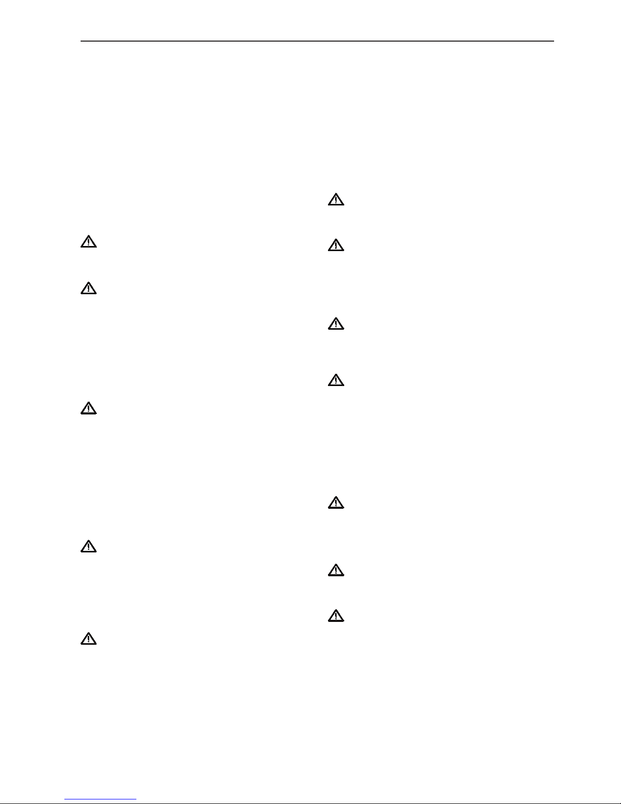
10
Examples of boats for medium and heavy duty commercial operation, Rating 1–2.
Examples of boats for light and medium duty commercial operation, Rating 2–3.
Engine application ratings
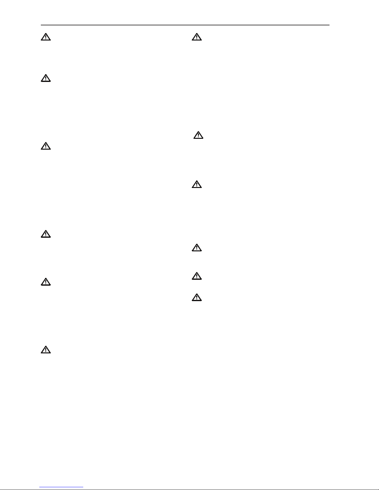
11
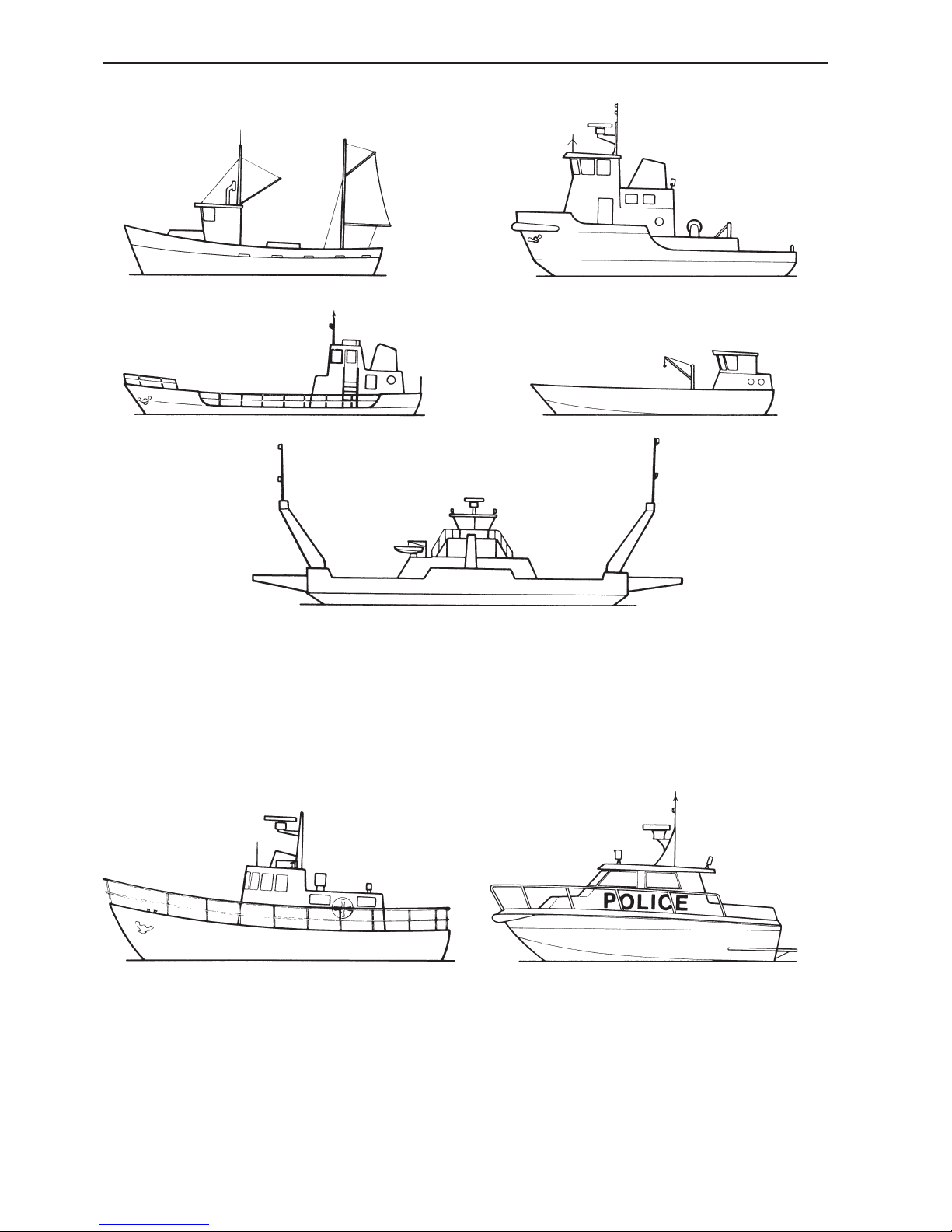
Examples of boats for light duty and special light duty commercial operation, Rating 3–4.
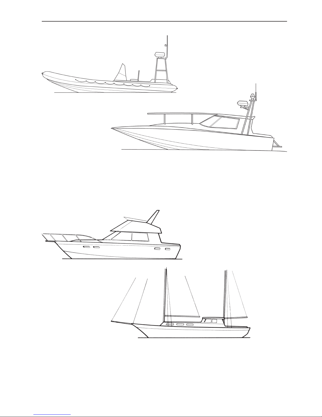
Examples of pleasure crafts, Rating 5.
12
Marine engine environment
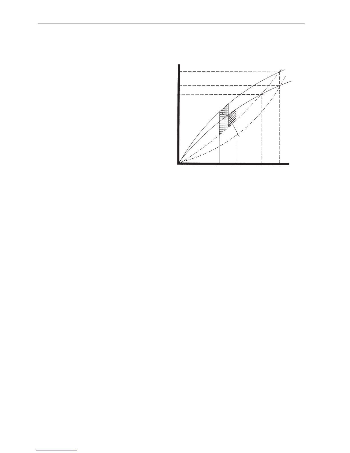
Power losses due to atmospheric conditions
Losses due to large propeller
Critical
area
Rated
rpm
rpm
A
Power
B
C
The marine engine and its environment
Marine engines, like engines for cars and trucks, are
rated according to one or more power norms. The
output is indicated in kW, usually at maximum engine
speed.
Most engines will produce their rated power provided
they have been tested under the conditions specified
by the power norm and have been properly run in.
Tolerances according to ISO standards are usually ±
5%, which is a reality that must be accepted for line
produced engines.
Measuring output
Engine manufacturers normally assign an engine’s
output to the flywheel, but before the power reaches
the propeller, losses occur in the transmission and in
the propeller shaft bearings. The amounts of these
losses are 4-6%.
All major marine engine manufacturers indicate
engine power according to ISO 8665 (supplement
to ISO 3046 for leisure boats), based on ISO 3046,
which means that the propeller shaft power will be
given. If an exhaust system is optional, engine tests
are conducted with a backpressure of 10 kPa. If all
engine manufacturers followed the same test procedure it would be easier for a boat producer to compare products from various suppliers.
Engine performance
Engine output is affected by a number of different
factors. Among the more essential are barometric
pressure, ambient temperature, humidity, fuel thermal
value, fuel temperature (not EDC engines) and backpressure. Deviation from normal values affects diesel
and petrol engines differently.
Diesel engines use a large amount of air for combustion. If the mass flow of the air is reduced, the first
sign is an increase in black smoke. The effect of this
is especially noticeable at planing threshold speed,
where the engine must produce maximum torque.
If the deviation from normal mass flow is substantial,
even a diesel engine will lose power. In the worse
case the reduction could be so large that the torque
is not sufficient to overcome the planing threshold.
The above figure illustrates the consequences of climate variation.
Point A is where rated power from the engine is equal
with the power absorbed by the propeller. Selection
of the propeller size at this point is correctly located
for utilising max. rated power at a certain weather
and load condition.
If atmospheric conditions cause the power to drop
to point B, the propeller curve will cross the output
curve from the engine at point C. A secondary performance loss has occurred because the propeller
is too large. The propeller reduces the rpm from the
engine.
By replacing the propeller with a smaller one, the
power curve of the engine will cross at point B, making it possible to regain previous rpm, but at reduced
power.
For planing or semi-planing boats, the planing threshold ("hump" speed), which mostly occurs at 50 - 60%
of max. speed, is the critical area. In this section it is
important that the distance between the engine max.
power curve and the propeller curve is large enough.
Marine engine environment
13
Other factors affecting performance
It is important to keep the exhaust backpressure at a
low level. The power losses caused by backpressure
are directly proportional to the increase of backpressure, which also increases the exhaust temperature.
Thermal values differ between markets and influence
engine output. Environmental fuel, which is compulsory in some markets, has a low thermal value. Engine output may be reduced up to 8% compared with
fuel specified in the ISO standard.
The weight of the boat is another important factor
affecting boat speed. Increased boat weight has a
major effect on boat speed, especially on planing and
semi-planing hulls. A new boat tested with half filled
fuel and water tanks and without a payload easily
drops 2-3 knots in speed when tested fully loaded
with fuel, water and equipment for travelling comfort.
This situation arises because the propeller is often
selected to give maximum speed when the boat is
tested at the factory. It is therefore advisable to reduce propeller pitch by one or more inches when encountering hot climate and user load conditions. The
top speed will be somewhat reduced but the overall
conditions will improve and provide better acceleration, even with a heavily loaded boat.
With this in mind it is important to remember that fibreglass boats absorb water when they rest in water,
making the boat heavier over time. Marine growth, an
often overlooked problem, also has a serious effect
on boat performance.
Propeller selection
Naval architects, marine engineers or other qualified
people should choose the propeller. The required engine performance data to make the proper propeller
selection is available in technical literature.
With regard to the propeller selection it is important
to achieve correct engine RPM. For this purpose we
recommend Full Throttle Operating Range.
In order to achieve good all-round performance the
propeller should be selected within this range.
When the prototype and first production boat is built,
a Volvo Penta representative and a boat manufacturer should undertake a fully loaded trial of the vessel
as near as possible to the conditions that the boat will
meet in the field. The most important conditions are:
• Full fuel and water on board
• Ballast evenly distributed throughout the boat to
represent the owners’s equipment including such
things as outboards, inflatable dinghies etc.
• Genset/air conditioning equipment and all domes-
tic appliances fitted.
• Adequate number of people onboard.
Once the vessel is subjected to these conditions a
full engine/propeller trial should be undertaken where
all engine parameters are checked, i.e. engine rpm,
fuel consumption, rel. load, ref. rpm (EDC) boost
pressure, exhaust temperatures, engine space temperatures etc.
When the correct propeller has been established
based on the tests, the engine rpm should be within
the " Full Throttle Operating Range" at full load.
However, it is advisable to reduce pitch some more
to handle varying weather conditions and marine
growth. For this reason boat manufacturers must follow the actual situation of their differing markets.
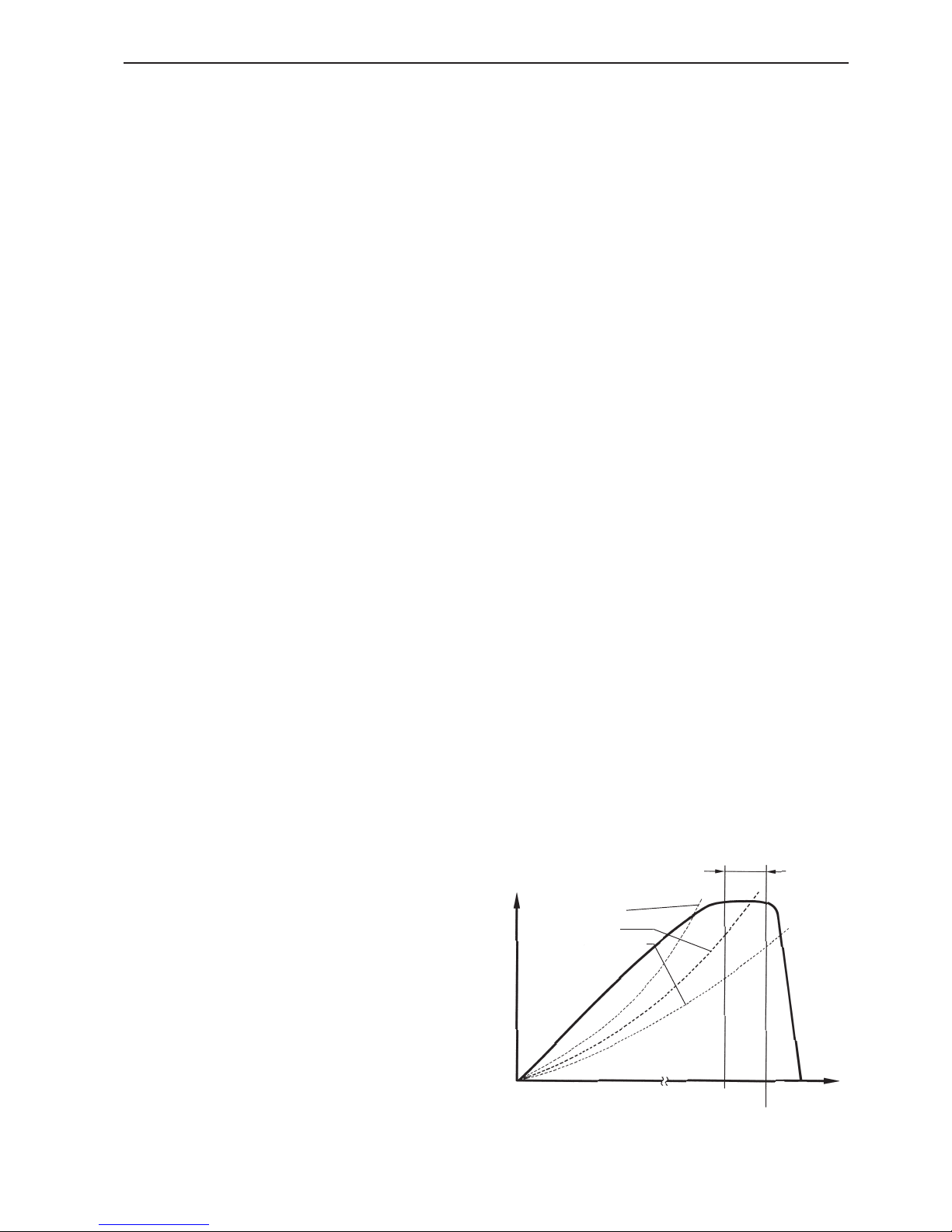
Propeller (too big)
Propeller (OK)
Propeller (too small)
Rated
Governor
cut out
100% of full
output.
Full throttle
operating
range
Engine output, kW
rpm

Marine engine environment
14
Full throttle operating range
The performance of any marine engine is largely
dependent upon the correct matching of the propeller to the horsepower available from the engine. All
Volvo Penta engines have an operating speed range
where the engine develops its rated horsepower, this
is titled "Full Throttle Operating Range". A propeller
that has been sized to demand the rated horsepower
of the engine will allow the engine to operate at its
rated speed. Should the propeller load be less than
the rated horsepower the engine will operate above
the specified range. A propeller load that is greater
than the engines rated horsepower will result in the
engine not being able to reach the rated rpm and will
therefore overload the engine.
An engine in a newly launched vessel is likely to be
exposed to the lightest loads. This is because the total displacement of the vessel has yet to be reached,
the hull has not become fouled and all onboard systems are running at optimal efficiency. It is therefore
important that after launching and on sea trials the
engine be able to achieve slightly more than the rated
rpm under normal conditions.
Marine engine environment
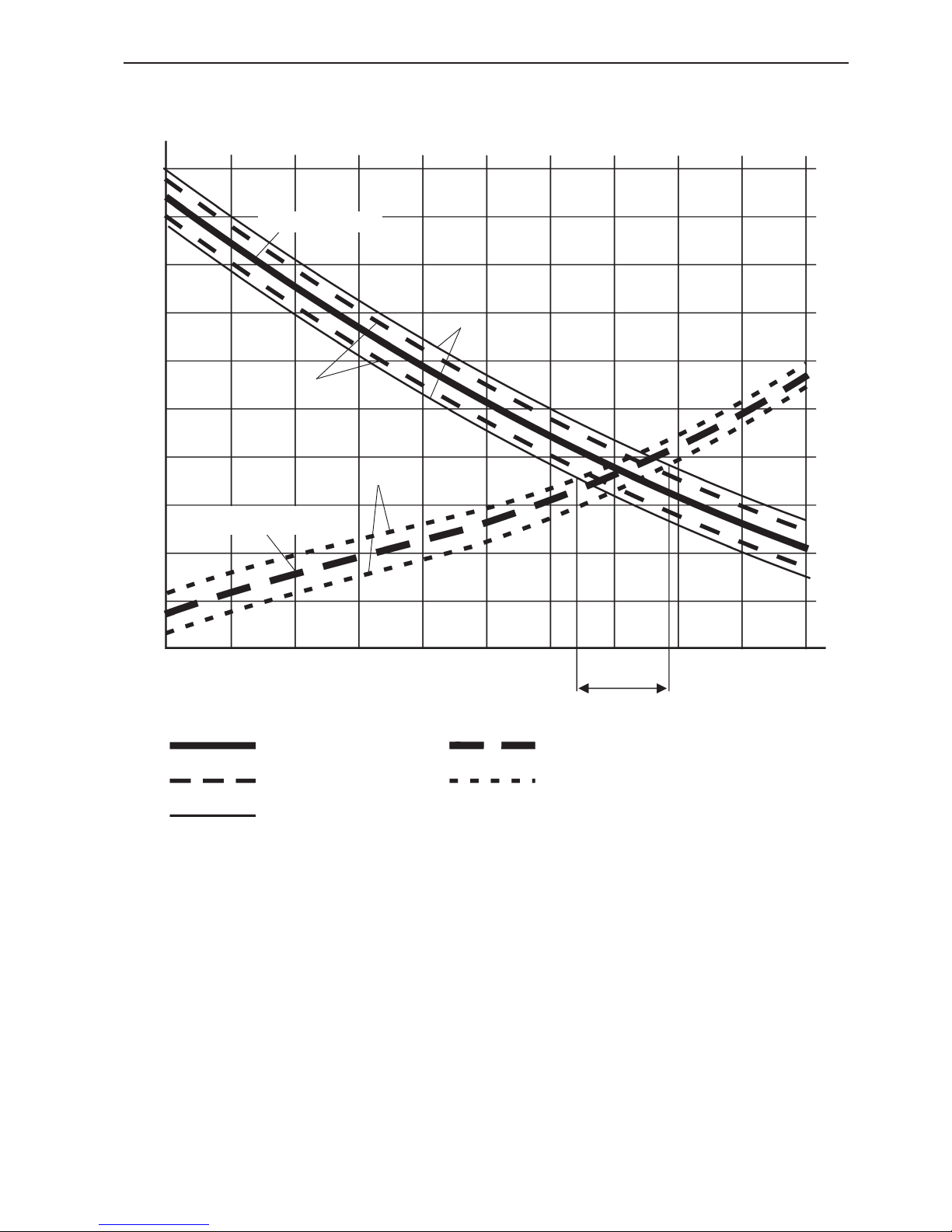
15
Typical sample of a planing hull and how displacement and engine output tolerances effects
performance
Nominal engine output
Engine output ±3%
Propeller precision
tolerances ±3%
Nominal displacement 13 tons
Displacement ± 3%
Thrust/
power
Speed
Knots
20 22 24 26 28 30 32 34 36 38 40
20
22
24
26
28
30
40
38
36
34
32
Max. tolerance
range
Displacement / hull
resistance
C
Engine output / Thrust
A
B
C)
A)
B)
Production tolerances
In order to ensure optimal performance of the vessel and long engine life, correct propeller size is essential. Selecting the correct propeller will enable the
engine to develop its full power and provide the performance that is expected.
There are a number of factors with their tolerances
that can greatly affect the performance of the vessel.
These must be recognised for correct engine/propeller selection. These factors are:
A) Engine power can vary within international power
standard tolerances.
B) The calculated hull resistance/displacement may
vary within certain limits.
C) The power absorbed by the propeller with regard
to propeller manufacture precision tolerances generally affects engine rpm.

16
General information about classification
The classification procedures outlined below are
general and can be changed from time to time by
the Classification Societies.
The classification procedure was originated for the
purpose of introducing similar and comparable rules
and regulations for, among other things, production
and maintenance of ships and their machinery and
equipment. As a result of these rules and regulations
"safety at sea" could be improved and better documentation could be introduced for insurance matters.
The government authorities in most countries concerned with shipping have authorized the Classifica-
tion Societies to handle these rules and make sure
they are followed. The classification procedure dates
from long ago. It can be noted that Lloyd’s Register of
Shipping, London, was founded as early as 1760.
The major Classification Societies are:
• Det norske Veritas (DnV)
• Lloyd’s Register of Shipping (LR)
• Bureau Veritas (BV)
• American Bureau of Shipping (ABS)
• Germanischer Lloyd (GL)
• Registro Italiano Navale (RINA)
• Russian Maritime Register of Shipping, (RMRS)
• China Classification Society (ZC)
• Korean Register of Shipping (KR)
• Nippon Kaiji Kyokai (NK)
As examples of government authorities responsible
for ships’ seaworthiness we can note the following:
Sjöfartsverket, Sweden (National Maritime Administration), Sjöfartsdirektoratet, Norway, Statens Skibtilsyn, Danmark, Department of Transport, England.
The Classification Societies have established their
rules so that the authorities’ requirements are covered. The authorities, however, have requirements
for lifeboats that are not included in the rules of the
Classification Society.
In 1974 an International Convention for the Safety of
life at sea (SOLAS) was adopted by the International
Maritime Organisation (IMO). This document ratifies
uniform rules for life saving equipment on board lifeboats and rescue boats.
NOTE! This installation manual does not give full
information concerning classification. Please contact
an authorised classification society for complete information.
Classified engine, range of use
An engine with equipment that is used in a classified
vessel must be approved by the Classification Society, which handles matters relating to ships’ seaworthiness. The rules apply for instance to the propulsion
engine, auxiliary engine, power take off, reverse gear,
shaft and propeller.
This means that if an installation needs to be classified it must be stated clearly when addressing inquiries and quotation requests to AB Volvo Penta.
Special rules for different operational
conditions
The Classification Societies have, in general, different rules relating to the following:
Varying shipping conditions e.g:
• Shipping in tropical water
• Coastal shipping
• Ocean shipping
• Operation in ice (several different classes)
Type of load e.g:
• Passenger shipping
• Tanker shipping
• Reefer shipping
Type of manning e.g:
• Unmanned machine room
• Manned machine room
These rules are adapted so that each vessel can be
assumed to function faultlessly in the area or type of
operation for which it is approved.

General information about classification
17
Type approval
To be able to classify an engine, the type of engine
must first be type approved. In such cases, where
Volvo Penta is concerned, an application for type
approval is sent to the Classification Society in question, followed by the required drawings, data and
calculations.
After certain tests, checks and possible demands for
supplementary information, the engine is type-approved for a specified maximum power at a given
rated speed. This type approval must not however be
considered as a classification; it is only a certificate
that states that the engine type with specified power
can be classified. Final classification can only be
given when all components are approved and the
installation and test run in the vessel are completed
and found to be in order by the local surveyor.
Procedure for classification
(Product orientated)
To earn a classification certificate, the engine, its
components, the installation and the test run must
be approved by a surveyor from the Classification Society in question. The surveyor can, after
final inspection and with certificates from the built-in
machinery, issue the final certificate for the vessel.
(Thus the final certificate cannot be issued by AB
Volvo Penta).
Usually the procedure is initiated as a result of a request from a customer or dealer who has to deliver
an engine in a classified installation. For these orders
Volvo Penta normally starts with a "type approved
engine". During production of such an engine the
surveyor checks the production if there is no quality
assurance system agreement.
Separate certificates are issued for the following
components:
• Crankshaft, connecting rods,
• heat exchanger, oil cooler,
• turbocharger, coupling,
• reverse gear, propeller and shaft,
• generator, alternator.
The surveyor then checks the pressure testing and
test running of the engine, after which a certificate for
the engine itself is issued.
Torsional Vibration Calculations (TVC) must be
carried out for the complete installation of the engine
in the vessel and approved by the Classification Society.
These calculations are carried out to check that no
critical torsional vibrations occur in the speed range
in which the engine is operated.
The procedure can differ somewhat depending on
the Classification Society in question.
Simplified rules for engines produced in
series (Process orientated classification)
Most Classification Societies can use simplified classification procedures based on a well implemented
Quality Assurance System at the Engine Manufacturer.
As Volvo Penta fulfills Quality Assurance based on
Swedish standard SS-ISO 9001, AB Volvo Penta has
been approved by the Classification Societies below:
• Lloyd’s Register of Shipping (LR)
• Registro Italiano Navale (RINA).
18
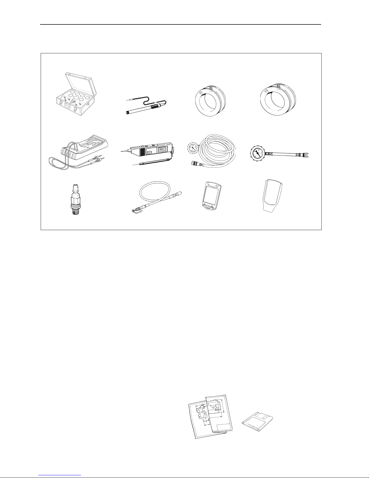
Special tools
Installation tools and literature
Dimension drawings
Drawings for current program, leisure and commercial applications are available at:
http://www.volvopenta.com
885151 Box with gauges and connections. For measuring pressures and exhaust temerature.
885156 Calomel electrode. For measuring galvanic
and stray current (use in combination with multimeter
P/N 9812519).
885309 Flange D5. For measuring exhaust backpressure and temperature.
885164 Flange D7. For measuring exhaust backpressure and temperature.
9812519 Multimeter.
9988452 Digital probe tester.
9996065 Manometer. For measuring fuel feed pres-
sure, not D9/D11/D12.
9996398 Manometer D9/D11/D12/D16. For measuring fuel feed pressure.
9996666 Connection D9/D11/D12/D16. For measuring fuel feed pressure.
9998494 Hose and nipple D9/D11/D12/D16. For
measuring fuel feed pressure.
3838620 VODIA tool*. For reading fault codes in clear
text.
3838621 Docking station for the VODIA tool*. Connects the VODIA tool to the engine.
*Order via VODIA WEB on Volvo Penta Partner Network
885151 885156
9988452 9996065
9996666
9812519
9998494
9996398
885164885309
3838620
3838621
Installation tools and literature
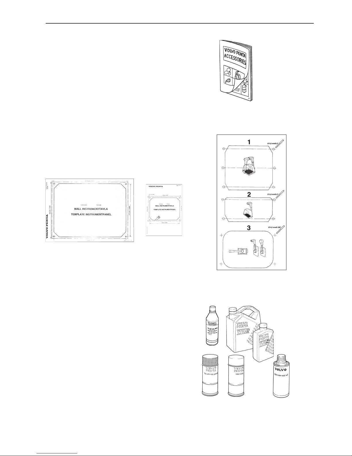
19
Templates
• Instrument panels
• Controls
Installation instructions and templates are included in
the kits.
Chemicals
A wide range of chemical products are available from
Volvo Penta. Some examples are:
• Oil and coolant
• Sealant and grease
• Touch-up paint
• Refer to "Volvo Penta Accessories & Maintenance
Parts"
Publications
• Installation, Electronic Vessel Control EVC
• Installation, Marine Commercial Control MCC
• Marine Electrical Systems, Part 1
• Inboard propellers and speed calculation
• Installation, Water Jet
• Sales Guide Marine Propulsion Diesel Engines
• Volvo Penta Accessories & Maintenance Parts
• Workshop Manuals
• Operator’s Manuals

20
Design concepts of propulsion systems
There are different types of engines, reverse gears and front drive systems, depending on the available space
and other requirements during the installation.
Follow the manufacturer’s instructions when installing components and equipment not supplied by Volvo Penta.
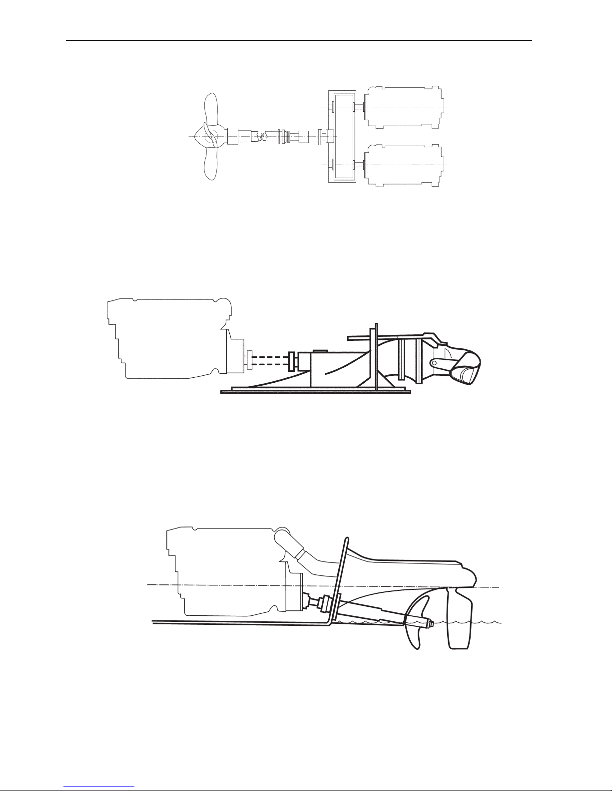
Reverse gear, various types
Coaxial
The engine’s crankshaft and the reverse gear’s output shaft are on the same level. The propeller shaft
and crankshaft are in-line.
The engine and reverse gear form one unit. The compressive forces from the propeller are absorbed by an
axial bearing in the reverse gear.
Drop centre, parallel
The engine’s crankshaft and the reverse gear’s output shaft are parallel. The output shaft is on a lower
level than the crankshaft.
The engine and reverse gear form one unit. The compressive forces from the propeller are absorbed by an
axial bearing in the reverse gear.
Coaxial down angle
The extension of the engine crankshaft centre line is
angled in the reverse gear. The angle of the propeller
shaft deviates from the angle of the crankshaft.
The engine and reverse gear form one unit. The compressive forces from the propeller are absorbed by an
axial bearing in the reverse gear.
Drop centre, down angle
The engine’s crankshaft and the reverse gear’s output shaft are on different levels. The angle of the propeller shaft deviates from the angle of the crankshaft.
The engine and reverse gear form one unit. The compressive forces from the propeller are absorbed by an
axial bearing in the reverse gear.
Design concepts of propulsion systems
21
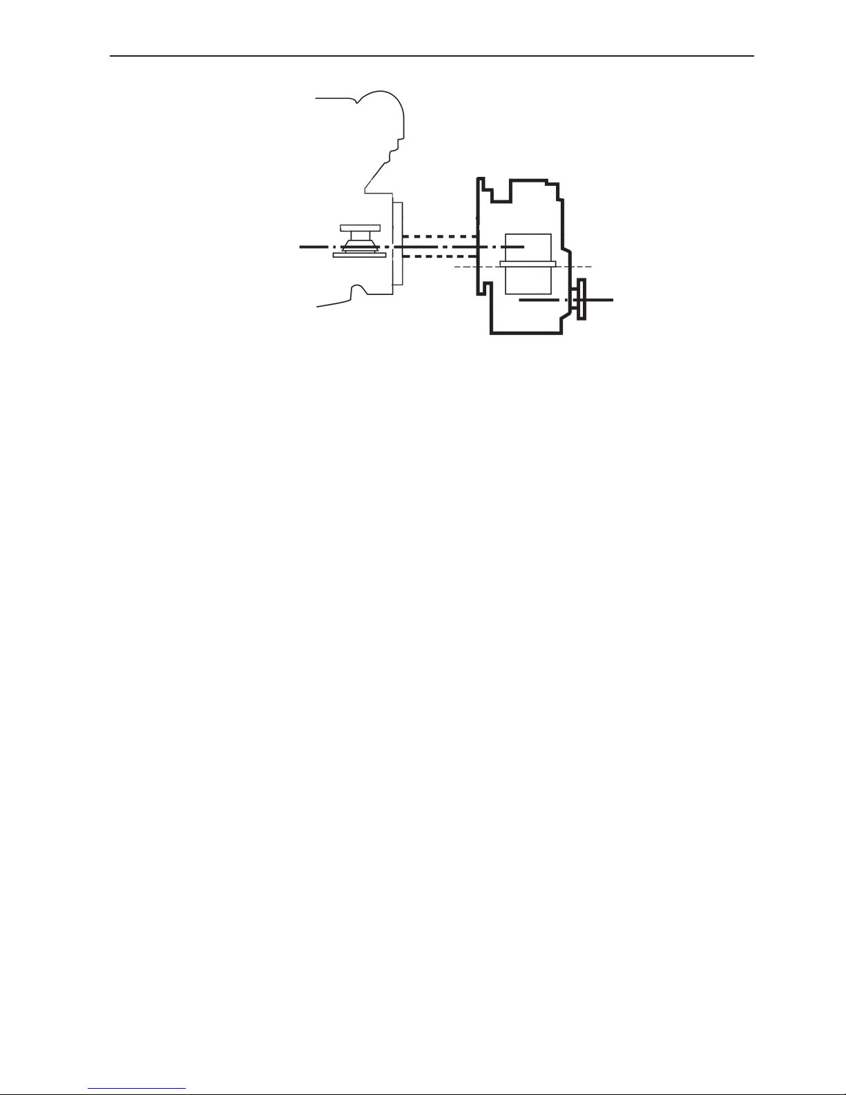
Remote reverse gear
The reverse gear is separated from the engine and
mounted on the engine bed or on a separate bed.
Torque is transferred via a flexible coupling through
a shaft. The angle of the propeller shaft can deviate
from the angle of the crankshaft.
The remote reverse gear must first be installed and
carefully aligned nominated by the propeller shaft.
Then the couplings are fitted and the engine is
aligned to the reverse gear. For final location and to
prevent possible shock loads, lugs must be welded in
front of and behind the brackets on each side. Wedges are then driven in and secured by welding when
alignment is completely finished.
Design concepts of propulsion systems
22
V-drive, various types
Close coupled V-drive
The engine and reverse gear form one unit. The axial
forces from the propeller are absorbed by an axial
bearing in the reverse gear.
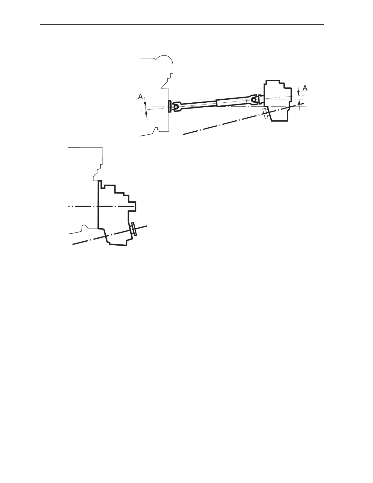
Remote V-drive
The reverse gear is separated from the engine and
mounted on a separate bed. Torque is transferred via
the propeller shaft, as illustrated in the diagram, or
via a flexible coupling.
The axial forces from the propeller are absorbed by
an axial bearing in the reverse gear.
The remote V-drive must first be installed and carefully aligned according to the propeller shaft. Then
the shaft and couplings are fitted and the engine is
aligned to the reverse gear. For final location and to
prevent possible shock loads, lugs must be welded in
front of and behind the brackets on each side. Wedges are then driven in and secured by welding when
alignment is completely finished.
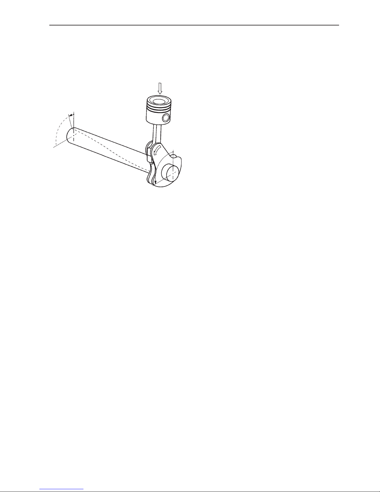
For the application of cardan shafts, follow the installation instructions from the cardan shaft supplier. A
rule of thumb share the joint angle, where A ≈ A.
Design concepts of propulsion systems
23
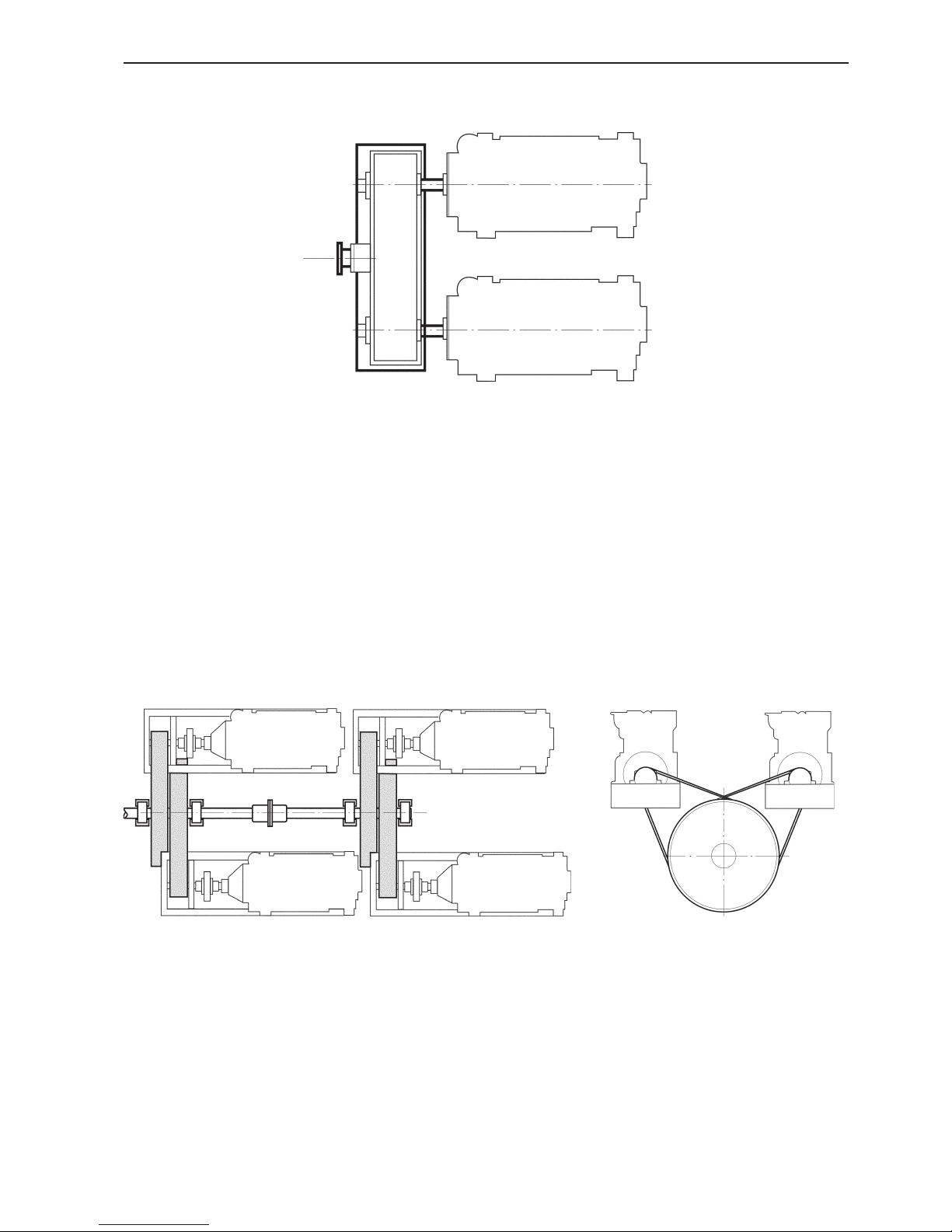
Twin engine package - Twin gear
Multi-belt transmission
The twin engine package over one marine gear is a
concept used by Volvo Penta over a period of time.
The concept is based of the utilisation of the commonality of two high volume produced high speed
marine diesel engines power over the twin marine
gear to one common propellershaft. The twin gears
are available from a limited number of manufacturers
for fixed and controllable pitch propellers.
Volvo Penta does not market these gears as a marine
engine package. If this application concept is considered attractive, further information and support can
be acquired from Volvo Penta Sales Organisation.
Another transmission concept is the multi- belt utilising a number of diesel engines driving a common
shaft to a remote marine gear. The engines in this application are normally disengagable by a clutch. The
concept is proven very functional to obtain the total
power requirement beyond the conventional single or
twin installation. The system can theoretically operate
a marine gear for either a fixed or a controllable pitch
propeller. Volvo Penta does not market this concept
as a whole but could provide considerable know-how
through the sales organisation if this system solution
is considered.
Design concepts of propulsion systems
24
Controllable pitch
Water Jet
Water Jet drives work according to principles of jet
propulsion. A jet of water is generated whose thrust
sets the vessel in motion.
There are different types of water jets, a direct drive
or one with a marine gearbox enabling clutch in/out
and backflushing the system for cleaning purposes.
See Installation, Water Jet.
Surface drive
Controllable pitch is used as an alternative to a fixed
propeller. The pitch of the propeller blade is normally
regulated by means of a built-in function in the reverse gear.
A number of surface piercing propeller systems are
available on most markets. These systems are aimed
at high speed applications where the systems are
highly efficient. The systems are available with rudder arrangements or steerable drive unit. At planing
speed the propeller operates with half of its diameter
submerged. At lower speed the propeller is usually
submerged and due to its high pitch torque, has
greater absorption in comparison to a conventional
propeller.
25
Torsional vibrations
Torsional vibrations occur due to forces on the crankshaft caused by the piston and connecting rod during
the power stroke. These forces tend to deflect the
crankshaft, including angular displacement of the
shaft.
• The frequency is the time rate of torsional vibra-
tions
• The amplitude is the angular displacement due to
torsional vibrations.
• The critical speed is the speed at which the ampli-
tude of the vibrations in a shaft are maximum and
could result in stresses that exceed the safe limit
of the material.
• Torsional vibrations may also be caused by torque
vibrations at the propeller.
Torsional vibration approvals
The object of a Torsional Vibration Calculation (TVC)
is to locate the critical speed points and to ensure
that these critical speeds are outside the operating
range of the engine.
Disregarding the torsional compatibility of the engine
and driven equipment may fracture the crankshaft
and flywheel bolts and overheat the vibration damper.
Since compatibility of the installation is the system
designer’s responsibility; it is also his responsibility to
obtain the theoretical torsional vibration analysis.
Volvo Penta standard propulsion packages would
generally not require TVCs unless front end PTO is
utilised. TVCs are recommended for all heavy duty
commercial applications. In classified installations, a
TVC must be performed.
Torsional analysis data
Volvo Penta will do a torsional analysis on receipt of
the necessary details from the customer. The following technical data is required to perform a torsional
analysis:
A. Operating speed ranges. Lowest speed to highest
speed.
B. Maximum power output.
C. Detailed drawing of rotating components.
D. Inertia of rotating components and location of
masses.
E. A general layout drawing is needed for more com-
plicated installations.
For the purpose of TVCs, most drive line manufacturers provide shaft drawings, with moment of inertia
and their position on the shaft diameters.
Torsional vibrations and TVC calculations
Torsional vibrations and TVC calculations
26
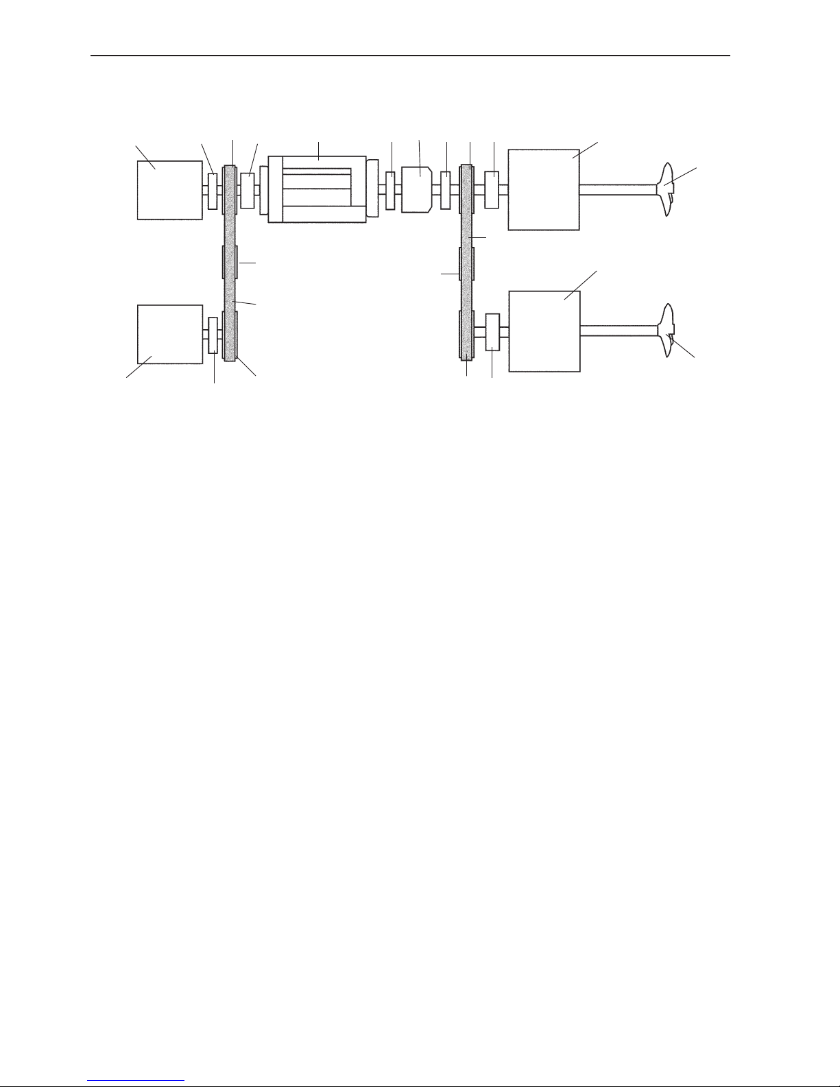
Example of a complex masselastic system
The Drive package, i.e. engine, flexible coupling,
and reverse gear, supplied by Volvo Penta has as
one unit the lowest possible torsion vibration level
in terms of standard propeller systems. A Torsional
Vibration Calculation (TVC) must be conducted by
Volvo Penta if other combinations are to be used.
Incorrectly selected components in the drive package
can result in abnormally high stress of the engine’s
crankshaft.
Routines for handling TVC
When a Torsional Vibration Calculation is request-
ed, it can be carried out by Volvo Penta.
The following procedure should be followed:
1. All necessary documents should be sent to the
Quality System and Classification Department,
which will issue an order number that will be the
reference number for future communication regarding the matter.
2. All communication in TVC matters should be
directed to the Quality System and Classification Department. The responsibility for internal
handling is on Quality System and Classification
Department at the production unit in Göteborg.
1. Engine
2. Coupling, disengagable
3. Pulley
4. Coupling
5. Pump, compressor etc. with
the same rpm as engine
6. Reduction gear, reverse gear
12
2
11
3
10
5
4
3
2
1 4
6
7 3
8
9
11
3
2
8
9
2
10
7. Flange coupling
8. Alternator, compressor
9. Propeller shaft and propeller
10. Belt
11. Belt tensioner
12. Pump, compressor
3. The cost for TVC will be charged according to the
following principle: If the received documentation
is complete from the beginning a basic calculation
will be charged according to the price list.
Each additional operation, e.g. recalculation due
to missing or wrong information or complex calculations, will be charged at actual cost.
It is therefore of extreme importance that the doc-
uments for the calculation are complete and that
no information is missing.
27
General arrangement and planning
Performance requirements
What are the top speed and cruising speed requirements?
The boat/vessel
Define the category of hull type:
• Displacement
• Semi-planing
• Planing
Consider the boat size and estimate weight, LCG
(Longitudinal Centre of Gravity) etc. Drawing information (line drawings) is requested, in the best case
resistance data from tank tests.
Propulsion system
Search for the most suitable propulsion system and
engine geometry. Think about the characteristics of
different propulsion systems.
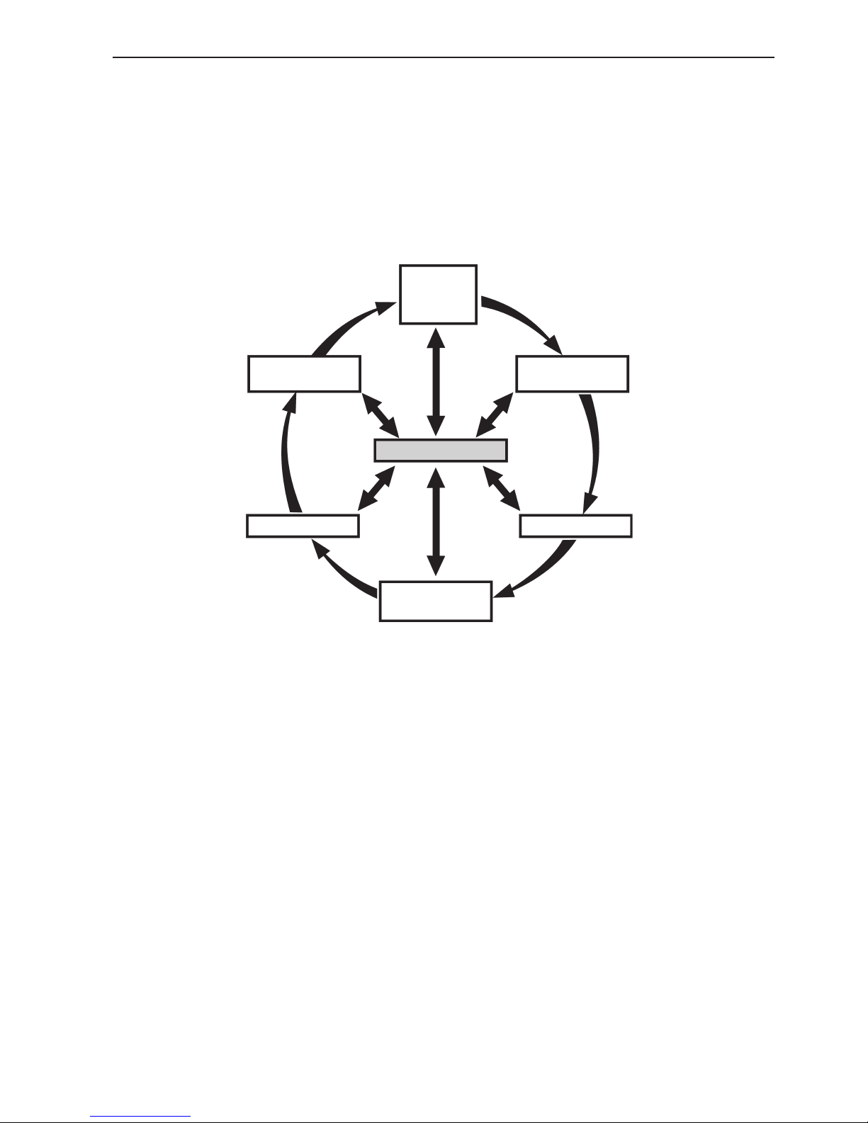
Choice of engine
To provide the best performance and characteristics
of an installation it is important to elaborate and iterate the information shown in the illustration below.
Trial and error is often needed to finally find the essential set of "performance" requirements the instal-
BOAT
VESSEL
REVERSE GEAR
AND PROPELLER
PERFORMANCE
LIMITATIONS
PROPULSION
SYSTEM
POWER
REQUIREMENT
ENGINE
lation aims to fulfil. Analysis of each contribution may
vary depending on the dominating priorities such as
top speed, economy, safety, etc. Consult Volvo Penta
literature and computer programs or contact the Volvo
Penta organisation for assistance.
Limitations
Consider possible limitations such as engine and propeller dimensions.
Power requirement
Use the data to define the required power. Do not
forget to consider power losses due to PTOs, climate,
fuel qualities etc.
Engine
Consult Volvo Penta sales literature for the corresponding engine, giving minimum required power at
the correct duty rating. Check the available reverse
gear ratios.
Reverse gear and propeller
Calculate for the optimum gear ratio as well as propeller type and size.
General arrangement and planning
28
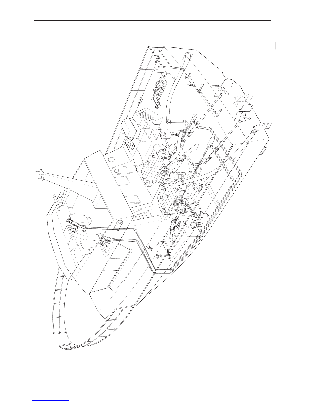
The illustration shows an example of a twin instal-
lation with two types of wet exhaust systems, one
"Aqua-lift" system and one installation with riser and
exhaust boot.
The starboard propeller shaft is mounted with a wa-
ter-lubricated stuffing box with water tapped off from
the reverse gear oil cooler. The port propeller shaft
has a grease-lubricated stuffing box.
The control is an electrical to mechanical system.
Installation example
This illustration is also avail-
able as a four-colour poster
(size 500 x 700 mm).
Publ. no. 7738092-1

General arrangement and planning
29
Plan the engine room so as not to hinder engine
servicing work. Compare with the instruction book
and make sure that all filter replacesments, oil changes and other servicing measures can be carried out
normally. Also ensure that it is possible to install and
remove the engine.
Before starting any installation work, make sure
that up-to-date dimensional drawings for the
engine and its equipment are used. Dimensional
drawings provide all the necessary measurements
for installation, such as the distance from the centre
of the crankshaft to the engine brackets (reverse gear
brackets) and to the centre line of the propeller shaft.
Note that the small silhouette drawings on leaflets
and brochures should not be used for this purpose.
The engine and drive line should be installed in such
a way as to minimise noise and vibrations, i.e. air
noise and body noise (vibrations).
Vibrations from the engine and propeller are transmitted via the suspension and engine bed out in the
hull. Other channels are via the exhaust pipe, coolant
pipes, fuel pipes, cabling, and control cables.
Pressure shocks from the propeller are transmitted
through the water into the hull. Pulsating force on the
propeller goes into the hull via the support brackets,
bearings and seals.
If the propeller is at a large angle this pulsating
pressure and force can be considerable. Use of an
incorrect propeller can result in cavitation, which also
causes noise and vibrations.
Torsional vibrations from correctly selected components in the drive package are often negligible.
NOTE! Always consider international and local requirements.
1. Engine room layout
Only use updated and approved dimensional drawings. Study the drawings carefully. Consider soundproofing material, the engine’s movements when running and accessibility for servicing and repairs.
For twin installations, the distance between the engines should be sufficient to allow easy performance
of inspection and service work.
2. Weight distribution
Consider the weight distribution of the boat so that it
is evenly distributed even with different levels of fuel
and water in the tanks. Place heavy units so that the
boat is balanced around the centre of gravity according to the designer’s recommendations.
NOTE! Pay special attention to obtain the best centre
of gravity possible. This has a major influence on performance in planing boats.
3. Choice of engine suspension type
Choose the appropriate type of engine suspension
based on comfort requirements, type of use and engine/reverse gear arrangement.
The two major systems are fixed or flexible. In the
fixed system, the engine/reverse gear is directly bolted to the engine bed. While in flexible systems, the
engine/reverse gear is installed on flexible mounts.
Volvo Penta offers flexible mounts for a large variety
of engine/reverse gear combinations.
Select a shaft system depending on the type of coupling (rigid or flexible), shaft support, stuffing box etc.
4. Fuel system
Determine the type of fuel system. Choose to use
fuel hoses or fuel pipes. Consider classification rules.
Decide where to place extra water separating fuel filters and plan for the routing of fuel hoses and pipes,
fuel filler and venting hoses, shut off devices etc. Fuel
feed and return hoses or pipes should be placed low
in the engine room so as not to transmit extra heat to
the fuel.

General arrangement and planning
30
5. Cooling system
Determine the type of cooling system. Chose where
to place seawater intakes and seawater filters. Plan
the routing of hoses.
6. Exhaust system
Determine the type of exhaust system, wet or dry.
Plan the installation of the exhaust line components,
such as silencer and hoses.
7. Electrical system
Plan the routing of cabling and check the length of
instrument cable harnesses. Decide where to place
fuse boxes and main switches.
Avoid joints and cable connections where there is risk
of moisture or water. Do not make any joints or connections behind fixed bulkheads or similar which are
difficult to reach after finishing the boat.
8. Electrochemical corrosion
The potential problem of galvanic and stray current
corrosion must be considered when planning electrical installation and choosing the equipment to be
used. Plan for protected anodes.
9. Air supply, ventilation and soundproofing
Carefully study sizes of sufficient duct area and pay
attention to optimise the design of air inlet.
Plan the routing of the ducts (hoses) for the engine’s
air consumption and ventilation so that they do not
impede installation of the batteries, fuel tanks, etc.
Sound insulation in the engine room is of great importance to keep the sound level as low as possible.
Sufficient space for soundproofing material must also
be planned for. A condition for good sound insulation
is a sealed engine room with ducts as the only openings.
10. Controls and steering
Plan for the routing of control cables, steering systems, Dual station units (DS–units), etc. Allow accessibility for servicing and replacement.
When using mechanical control cables it is of great
importance to route the cables with as few bends as
possible to achieve smooth handling.
11. Power take-off
In order to operate miscellaneous small auxiliary
apparatus, power take-offs can be fitted from an additional pulley or on the drive gear casing.
If greater outputs are needed, a mechanical power
take-off can be fitted on the front end of the crankshaft.
The outputs permitted from the power take-offs are
described in the sales literature.

General arrangement and planning
31
Propeller theory
To get the best performance out of your boat, you
need to select the propeller and gearing that will suit
your particular boat, engine and speed range.
Below you will find a brief description of how propeller systems are designed. It is not just the engine capacity determines the speed of the boat; it depends
just as much on the efficiency of the reverse gear and
the propeller system. Using the right propeller system
will not only give you good fuel economy and higher
speed but you will also experience greater comfort,
with less noise and vibration.
The following description is very general and describes only superficially how propellers are designed. The propeller manual Propellers gives more
detailed information.
Planing boats
In planing boats over 20 knots, the size of the propeller depends on the engine power. To transfer the
power from the engine to the water, you need approximately 7–8 cm2 propeller blade surface per kW shaft
power. If the shaft is at an angle in relation to the flow
of the water, this requirement may be considerably
greater: 8–15 cm2/kW is reasonable, depending on
the angle of the shaft and the water flow.
At a shaft power of 400 kW, therefore, the propeller
blade surface may need to be 400 kW x 9 cm2/kW =
3 600 cm2.
This surface may be divided over three, four or five
blades.
The efficiency of a propeller blade diminishes when
it becomes far too wide in relation to its length. This
means that if the propeller diameter is limited in size
(as is often the case), it is better to select several
narrower blades (four or five) rather than three wide
ones, for example.
The angle of the propeller shaft should be as small
as possible. Shaft angles of less than 12° do not usually cause any major problems, but shaft angles of
more than 14–15° should be avoided.
The distance between the bottom of the boat and the
propeller blades should be at least 10% of the diameter of the propeller.
When you have selected the diameter of the propeller, you are ready to go on to select the pitch.
Propeller blades should no travel faster than 60–70
knots through the water at 70% of the maximum
propeller diameter. This means that the speed of the
propeller revolutions must be reduced when the engine capacity is greater, which requires a larger blade
surface and therefore a greater diameter.
The relations between pitch and diameter should be:
P/D =
0.90–1.15 at 20 knots
1.00–1.30 at 30 knots
1.05–1.35 at 35 knots
Generally, a larger propeller with narrow blades and
low revolutions is more efficient than a small, highspeed revolving propeller.
When the boat’s speed exceeds 24–28 knots, the resistance of the shafts, rudders and propeller supports
increase to a level where the improved efficiency
of the propeller is not beneficial. The resistance on
the propeller system can be reduced by reducing
the shaft diameter, selecting stronger materials and
reducing the rudders and surfaces of the propeller
supports. Lower gear ratios also mean thinner shafts.
It is necessary to find a balance between propeller
efficiency, water resistance on the shaft, etc.
Pitch
Diameter

General arrangement and planning
32
Displacement and semi-planing boats
Boats of less than 15 knots need propellers that are
as large as possible. For example, in a trawler it is
possible to save 20–30% fuel or to gain 20% greater
thrust when trawling by increasing the propeller diameter by 50% and reducing the propeller speed by
40%.
The blade surface of the propeller is designed according to the minimum of 0.17 m2 (0.26 in2 ) per ton
of thrust.
As described above, a large, slow-moving propeller
is preferable. At a speed of 12 knots, for example,
a three-blade propeller with a 50% blade area will
achieve an efficiency rate of approximately 57% if the
propeller blade cuts through the water at 50 knots
with 70% of its diameter. At a blade speed of 70
knots, approximately only 47% efficiency is achieved.
The formula:
propeller efficiency x shaft output (kW) x 1944
T (Newton) =
speed of boat (knots)
can be used to calculate the thrust.
Three-blade propellers are often more efficient for
large, slow-moving propellers than four-blade or fiveblade propellers. However, four-blade propellers usually produce less vibration, which is often preferable.
In general, there is a tendency towards four-blade
propellers. A suitable pitch ratio at 10 knots is 0.7–0.9
and at 15 knots 0.8–1.05.
As the best pitch ratio varies according to the speed
of the boat, it is necessary to decide whether the propeller should be at its best when trawling, e.g. with a
pitch ratio of 0.7, or whether it should be better when
not trawling with a slightly higher pitch ratio.
Adjustable propellers are an excellent solution for
trawlers, tugs and freighters.
As a very rough estimate, the bollard pull thrust can
be calculated using the formula
Adjustable propeller (N) 95–105 x kW
Fixed propeller (N) 80–90 x kW
An adjustable propeller fitted to "the right boat" (up to
10 knots) can therefore save a lot of fuel.
Speed range between 15 and 20 knots
Within this speed range, a large slow propeller is
preferable to a small, fast one. The blade surface is
designed as a compromise between kW/cm2 and m2/
ton of tractive force.
Propeller and performance computer
program
Over the last year, Volvo Penta has been developing
computer programs for calculating speed, gear ratios
and propellers. This is excellent for predicting speed
and propellers simply and safely.
The estimated speed in the individual computer
programs is based on the experience gained from a
number of installations.
Propeller calculations
Theoretical speed and propeller calculations are
made using well-established methods and a number
of practical test results, but are still a result of approximations and estimations. We believe that for a
standard type of boat they can give you a reasonable
good estimation, provided that correct and complete
input is available. However the Volvo Penta organisation can not take any responsibility for the final result
which only can be found out during a sea trial.

General arrangement and planning
33
Propeller selection
The combination of ratio, shaft diameter and propeller size can be calculated by using the Volvo Penta
computer program. Calculation of the correct propeller size can be done by the Volvo Penta organisation if so desired. In this case all details of the boat
(preferably drawings) must be provided in good time.
A = Engine full load curve
B = Propeller load curve (propeller OK)
C = Recommended max operating range
The propeller should be chosen with the greatest of
care. Consider the space between the hull and skeg.
Refer to propeller recommendations and propeller
shaft angles, and the recommendation for free space
between the propeller and hull. See information on
the following page.
On planing boats the bottom over the propeller is
often rather flat. The hull can be reinforced on the
inside to reduce noise and vibrations caused by the
propeller blade pulses.
A
B
C
rpm
kW
For the best propeller efficiency, the angle of the propeller shaft in relation to the water line should be as
small as possible. The larger the shaft angle the lower the efficiency. Shaft angles exceeding 12° should
be avoided if possible. This means that with the boat
lying still, the propeller angle should not exceed 12°.
This applies especially to planing boats. Larger shaft
angles may affect the speed, sound and vibrations
negatively.
Check the shaft angle. If the shaft angle exceeds 12°,
the use of a smaller propeller should be considered.
This can be compensated by more blades.
The keel or the propeller shaft brackets in front of the
propeller should have a profile creating a minimum
of drag and turbulence. Also the shape of a tunnel is
very important. A poor tunnel design can create a lot
of turbulence in the propeller and reduce the boat’s
buoyancy at the stern.

General arrangement and planning
34
Single and twin installations
The most effective method of propulsion is generally
achieved with a single installation. If more power is
required than is possible with a single installation,
two engines, each with a separate propeller shaft can
be fitted.
Improved manoeuvring is gained in two engine installations and separate propellers as the power output
can be controlled separately and independently for
each engine. One engine can be run reverse and the
other ahead when for example manoeuvring at low
speed.
Two or more engines coupled to a common transmission and one propeller is a third possibility.
∅
E
B
A
D
F
A
B
C
D
E
Ensure that there is sufficient space between the
propeller, hull, keel, skeg and the rudder. It should
be possible to move the propeller shaft at least 200
mm (8") aft to allow the removal of the reverse gear
or coupling. Also make sure that any transverse bulkhead does not impede its removal. Sufficient clearance, approx. 1 x the shaft diameter, must be provided between the propeller and the stern bearing to
prevent the propeller from pressing against the stern
bearing. Allowance should also be made for rope cutters if they are to be fitted. See figures on this page,
position (E).
The minimum distances to the hull, keel, skeg
and rudder.
∅ = Propeller diameter
A = 0.10 x ∅
B = 0.15 x ∅
C = 0.10 x ∅
D = 0.08 x ∅
E = Approx. 1 x shaft diameter
F = Shaft angle. Shaft angles exceeding 12° should
be avoided.
Example: The measurement (A) for a boat with a
propeller diameter 30" (762 mm) is 0.10 x 762 = 76
mm (0.10 x 30" = 3") minimum.
The measurement (A) must never be less than 50
mm (2"). For classification, the requirements of the
respective classification body must be followed.

General arrangement and planning
35
Ratio, Main type of Speed
approx. operation range
Work boats,
6:1–3:1 Displacem. boats, 4–12 kn.
High pulling power,
Towing, Trawling
Work boats,
3:1–2.5:1 Displacement boats, 8–17 kn.
Low speed planing boats,
mainly free run
Semi-planing to planing
2.5:1–2:1 boats, Patrol boats, 16–26 kn.
Sport fishing
and Pleasure boats
Planing boats,
2:1–1.5:1 Patrol boats, 25–35 kn.
Sport fishing,
and Pleasure boats
High speed planing
1.5:1–1:1 boats, high 35–45 kn.
performance,
Pleasure boats and
similar
Ratio, Main type of Speed
approx. operation range
Work boats,
4:1–3:1 Displacem. boats, 4–8 kn.
High pulling power,
Towing, Trawling
Work boats,
3:1–2.0:1 Displacement boats, 6–10 kn.
Low speed planing boats,
mainly free run
Semi-planing to planing
2.5:1–1.5:1 boats, Patrol boats, 10–15 kn.
Sport fishing
and Pleasure boats
Propeller rotation
For a single installation, a right or left-hand rotating
propeller can be chosen. The rotation direction is
sometimes dependent of the type of reverse gear being used.
For twin installation, the starboard propeller should
always rotate clockwise and the port propeller anticlockwise seen from the aft forward. Otherwise there
is a risk that air bubbles will be drawn down into the
water between the two propellers which can cause
ventilation.
Choice of reduction ratio
The propeller shaft usually has lower speed than the
engine. This is normally achieved with the reduction
in the reverse gear.
As a rule the largest possible ratio should be chosen
for slow-going displacement boats. It then follows
that the propeller diameter can also be relatively
large with high thrust within the applicable speed
range. Depending on the hull type and speed range,
a smaller ratio can be chosen for higher speed, if
required. See the table. This is to obtain highest
thrust within the respective speed range. If the ratio
is chosen outside of the recommendations the thrust
can be lower than the optimum calculated power. The
boat’s top speed is not necessarily affected.
A check must always be done that the hull has sufficient space for the propeller according to information
in chapter Propeller selection.
In order to select the optimal gear ratio a calculation
have to be made. The following tables could serve as
guidelines.
D9/D12/D16 engine revolution range 1800–2800
rpm with conversional shaft/propeller system
D5/D7 engine revolution range 1900–2300 rpm
with conversional shaft/propeller system

General arrangement and planning
36
A
C
C
B
B
Engine inclination
To ensure that the engine is sufficiently lubricated
and cooled, it is important that the maximum engine
inclination is not exceeded. The engine inclination
must be checked.
Care should be taken to avoid having the front end
lower than the flywheel end, i.e. in excess of permitted negative inclination, since this can affect lubrication of the engine and venting of the cooling system.
Each engine type has a maximum permitted en-
gine inclination while the boat is under way. This inclination includes both the installation inclination and
the trim angle that the boat/engine has when going
through the water.
A = The engine’s static inclination.
B = The boat’s trim angle under way.
C = Total inclination of engine under way,
maximum permissible inclination (A+B).
Max. engine inclination
Static (A) Under way (C)
Engine Flywheel Flywheel Flywheel Flywheel
down up down up
D5/D7, standard sump 10 0 15 0
D5/D7, shallow sump 5 0 10 0
D9, shallow sump 6 0 12 5
D9, V-drive system 5 0 5 10
D9, deep sump 13 0 18 5
D11, standard sump 7 0 17 10
D12, shallow sump 8 0 13 5
D12, deep sump 13 0 18 5
D16, standard sump 11 0 18.5 7.5
Flywheel down Flywheel up

General arrangement and planning
37
Engine centre distance,
twin installation
For twin installations, consideration must be given to
the minimum distance between the engines to allow
sufficient accessibility for service work. Larger distance also gives better manoeuvring capacities.
Check for a suitable distance by using the dimensional drawing.
Generally, the following minimum measurements
between the engine’s centre-lines (A) are recommended:
D5/D7 1050 mm (41")
D9/D11 1200 mm (47")
D12 1250 mm (49")
D16 1350 mm (53")
For installation of several engines on one propeller
shaft the distance between the engines is mainly
determined by the gears or belt transmissions with
which the engines are joined together. The requirement for access for inspection, service and repairs is
still applicable.
A
Weight distribution
General
The centre of gravity has a major influence on the
boat’s static and dynamic stability. It is therefore important to consider this for the both when loaded and
unloaded.
Planing and semi-planing hulls
For planing and semi-planing hulls especially it is important that heavy equipment such as engines, fuel
tanks, water tanks and batteries are positioned in a
way as to obtain the best possible trim of the boat in
the water.
Consider the weight distribution of the boat so that it
is evenly distributed even with different levels of fuel
and water in the tanks.
It is an advantage to install the fuel tanks away from
the warm engine room. The batteries should be
placed in a separate, well ventilated area if possible.
Figure A represents an installation with good weight
distribution and with a good trim angle.
Figure B represents a wrong type of installation with
a subsequent bad running attitude.
LCG = Longitudinal Centre of Gravity
LCG
LCG
Figure A
Figure B

General arrangement and planning
38
Accessibility for checking,
maintenance and repairs
When designing the engine room always pay attention to the accessibility needed to allow proper service and repairs to the engine. Also ensure that the
complete engine can be removed without damage to
the boat structure.
A written instruction may be of major help if engine
removal is necessary at a later stage.
NOTE! There must also be sufficient space for the
soundproofing material. Study the dimensional drawings of the relevant engine carefully.
Accessibility for maintenance
Some areas that normally require access for maintenance:
• Oil change and refill
• Change of oil filters
• Change of fuel filters
• Venting fuel system
• Change of air filter
• Check of belt tension
• Change of belts
• Removal of valve cover
• Change of seawater impeller
• Cleaning of water filter
• Venting cooling system
Accessibility for repairs
Some areas that may require access for repairs:
• Lower crank case inspection covers (if fitted)
• Removal of injectors
• Removal of cylinder head
• Removal of charge air cooler
• Removal of oil coolers
• Removal or change of electrical components
• Removal of flywheel and vibration damper
• Removal or change of reverse gear
• Removal of propeller shaft
• Engine removal

General arrangement and planning
39
Selection of engine
suspension
There are two types of engine suspension; flexible
mounting with rubber mounts and rigid mounting.
Flexible mounting
Flexible engine suspension (rubber mounts) can be
used together with low gear ratios. With higher ratios,
the torsion forces and propeller axial force become
excessive for the rubber mounts.
One condition for rubber mounts to be effective
dampers is that the engine bed is sufficiently rigid.
The bed must also be parallel to engine feet to avoid
tensions being built into the engine suspension. Tensions can increase the vibration level and also shorten the life span of the mounts.
NOTE! The elasticity of the rubber mounts must never be utilised to compensate for an inclined bed.
Flexible engine mountings provide good insulation
from vibration between the engine and the bed frame,
thus contributing to a low noise level. Dimensions for
flexible mountings, see chapter Building the engine
bed.
There are two types of rubber mounts: mounts that
are adjustable in the vertical plane, and mounts with
a fixed height that must be shimmed to the correct
height.
Flexible engine suspension, rubber mount
Flexible engine suspension, rubber mount
The rubber mounts are compressed during installation, therefore the engine should rest on the rubber
mounts for 12 hours before the height is adjusted.
Always follow the recommendations of Volvo Penta
when selecting the engine suspension. The use of
incorrect rubber mounts can result in abnormal vibrations, which in turn can cause damage to engine
components and also reduce the degree of comfort.
NOTE! When flexible engine suspension is selected,
all the connection of components to the engine must
be flexible.
The propeller shaft must have a flexible stuffing box,
or alternatively a flexible shaft coupling.
The engine’s connections for fuel lines, exhaust and
coolant must be flexible.

General arrangement and planning
40
V-drive
In all installations with a down angle propeller shaft
there will be a lifting force transmitted from the propeller shaft. In an installation of an engine with a
V-drive this force could be higher than that from the
weight of the engine and gear box.
Engine rubber
mount
Axial
component
Propeller
thrust
Vertical
component
1
This will create a lifting force to the engine mounts
fitted at the same end as the gear box. Therefore
all engines with a close coupled V-drive must be
equipped with mounts that are designed for this type
of installation at the rear end.

General arrangement and planning
41
1. Support bracket for front power take-off
2. Steel bed frame (U-member or L-member,
thickness 0.47–0.6" = 12-15 mm)
3. Front mounting bracket (about 10" = 250 mm high)
4. Inspection covers
5. Sheet steel shims (about 0.4" = 10 mm thick)
6. Rear mounting brackets (about 10" = 250 mm high)
7. Adjustment bolts (4 pcs) for engine heightwise position. To be
removed after completed installation
8. Bolt to adjust engine lateral position
Rigid mounting
Rigid mounting is often used for commercial service
and heavy hulls. The vibration of the drive package is
not particularly noticeable with a large hull.
It is very important that the bed is level where the
engine mounts rest since otherwise there is a risk of
building tensions into the suspension joint.
With rigid mounting, the engine mounts are bolted
to the engine bed with 10 mm (0.4") thick shims.
The shims need to be milled to the correct size in
conjunction with the final alignment together with the
propeller shaft.
1
2
3
6
7
5
4
8
4
An approved type of moulding compound (e.g.
Shockfast) can be used instead of shims, but only
when the engine has the correct alignment.
A flexible shaft coupling can be used to absorb
changes that may occur in the alignment of the engine / propeller shaft as a result of deformation of the
hull structure.

General arrangement and planning
42
Engine suspension vs
propeller shafting
NOTE! A flexible shaft coupling must never be fitted
together with a flexible mounted stuffing box. This can
cause vibration problems.
Stainless steel propeller shafts are available in different diameters. The shaft dimension should be chosen
based on the engine power output, gear ratio and
propeller shaft material.
The following installation alternatives
and combinations are recommended:
1. Engine with flexible mounts and
flexible shaft seal
In this case, a flexible shaft coupling
should not be installed.
1. Flexible engine mountings
2. Fixed shaft coupling
3. Flexible mounted shaft seal
4. Water lubricated stern bearing
L. Maximum distance between support
points. For calculation see page 50.
2. Engine with flexible mounts and
fixed shaft seal
1. Flexible engine mountings
2. Flexible shaft coupling
3. Fixed front stern bearing and shaft
seal
4. Water lubricated stern bearing
L. Distance between support points.
For calculation L max see page 50.
B. Distance reverse gear flange – sup-
port point.
Recommended B min is 6-10 x shaft
diameter.
B max is calculating in the same way
as L max.
1
1
3
L
4
2
1
1
2
3
B
L
4

General arrangement and planning
43
All reverse gears from the genuine Volvo Penta range
are fitted with built-in axial bearings for axial forces
from the propeller shaft. No extra thrust bearings
need to be fitted under normal load conditions. In the
case of ice going vessels with excessive pulsating
axial forces, an additional thrust bearing is recommended in the propeller shaft system. In such cases,
3. Engine with fixed mounts and
fixed shaft seal
1. Fixed engine mountings
2. Fixed shaft coupling. (Flexible cou-
pling as an alternative.)
3. Fixed front stern bearing and shaft
seal
4. Water lubricated stern bearing
L. Distance between support points.
For calculation L max see page 50.
C. Distance reverse gear flange – sup-
port point.
Regarding C min see page 50.
C max is calculated in the same way
as L max.
C
L
1
1
2
4
3
Flexible coupling
as an alternative
a flexible coupling must always be fitted between the
reverse gear and the thrust bearing so as to eliminate
axial stresses between the two thrust bearings.
If the unsupported propeller shaft length is too long, a
separate support bearing should be fitted. A support
bearing cannot absorb axial stresses.
1. Flexible coupling
2. Thrust bearing
12
Axial thrust bearing

44
Engine foundation
Aligning the boat
The installation work is made easier if the hull is
aligned horizontally before starting. Block up the hull
so that the calculated water lines, both longitudinal
and transverse, are parallel with the horizontal plane.
A spirit level is a good help.
Check when manufacturing the bed that the upper
bed plane, the mating plane, is parallel and correctly
positioned in relation to the centre line of the propeller shaft. A guide sleeve with the same diameter as
the propeller shaft can be used in the stern tube to
help with the alignment of the bed.
General
The engine bed should be dimensioned so that it is
rigid in all directions to distribute the load as much
as possible into the hull. The greatest possible area
of the engine bed, and with cross members, must be
fastened to the hull to give the best noise and vibration insulation.
Plane requirements, rigid mounting
It is very important that the engine bed is dimensionally stable when the engine has a rigid mounting.
The maximum height deviation (movement) between
the engine’s attachment plane must be within 3 mm
(0.12"). In other words it is important that the bed
is so torsionally and bending rigid that the plane
requirements are not exceeded as a result of movements in the hull in rough sea, or when the boat is
put on shore or into the sea.
Design
The bed should have a design basis that enables it to
absorb by an adequate margin the engine torque, the
compressive force of the propeller, and the dynamic
forces (mass forces) that occur during movement in
rough sea.
When designing the bed it is important that there is
sufficient space under the engine for the movement
of the engine, and that there is also access to the inspection covers (certain engine versions).
If possible the bed should be designed so that the
reverse gear and flexible coupling can be dismantled
and lifted out separately.
The engine bed can be built separately and then
carefully measured and bonded into the hull, or be
built up directly in the hull.
When designing the bed the dimensional drawings
for the engine and the boat should if possible be used
to check the space round the engine and the height
and position of the bed in relation to the propeller
shaft. The height depends on whether a flexible engine suspension is to be used or whether the engine
is to have a rigid suspension, and the inclination of
the bed should correspond with the inclination of the
propeller shaft. The height should include a shim of
10 mm (0.4") avoiding the bed being too high.
It is important to drain any water around the engine
bed to the location of the bilge pump.
The figure to the left shows an example of a well-designed engine bed.

Engine foundation
45
Fibreglass hull
Example of an engine bed in a fibreglass hull.
1. Flat bar
2. Spacer material
3. Fibreglass
3
1
2
The engine bed in fibreglass should be designed so
that it is rigid, both vertically, longitudinally and transversely, to distribute the load as far as possible to the
hull. The bed is often built as a box construction. As
much of possible of the engine bed, including cross
members, should be attached to the hull to ensure
the best possible noise and vibration insulation.
The engine bed can be built up separately and then
carefully measured and bonded to the hull, or be built
up directly in the hull. It is important that the bed connects to the hull with a large radius built up of several
layers of fibreglass.

Engine foundation
46
Steel, aluminium or wooden hull
Example of engine bed in a steel or aluminium hull.
The bed frame in a steel or wooden boat should be
designed as a welded steel structure. The plate thickness should be sufficient to achieve a dimensionally
stable structure.
In a steel boat, the engine bed plane is welded to
each frame rib along their entire length.
In a wooden boat, the bed should be bolted to the
frame ribs with bolts and nuts.
The length of the engine bed should be extended as
far as possible to distribute the load.
If the engine has an extra PTO in the front end that
requires extra support, the bed should be designed to
accommodate this support. There must be space in
front of the PTO so that it can be dismantled.
Take into consideration and calculate brackets and
foundations etc. for other systems, fuel and exhaust
systems etc., and for extra equipment.
NOTE! If the engine in question is equipped with
inspection covers it is highly recommended (if classified, a must) to build mounting brackets (A) high
enough to ensure accessability.
A
A

Engine foundation
47
Building the engine bed
The engine bed position is determined by the position of the shaft. After measuring carefully, cut a hole
in the stern large enough for the stern bearing to be
put loosely in place.
Alternative 1
The engine can be used as a fixture to determine
the position of the engine bed. The engine must be
aligned to the propeller shaft. The shaft can temporary be installed and located in a correct position.
Alternative 2,
parallel gearboxes only
Another method to fix the engine bed without a fixture
or the engine is to apply a line from the rear end (3)
centered in the stern tube (2) to a fixed point (5) forward of the engine bed. The measurement (A) should
be equal to the rulers (1) within 0-2 mm (0-0.08").
See figure.
Ensure that the rulers are horizontal athwartship.
Fixed point. Sterntube is
not fixed, moulded or bolted.
Alternative 3
In serial production or frequent installation work a
fixture could be manufactured to position the bed
planes.

Engine foundation
48
When designing the engine bed, make sure that the
space for the flywheel housing, the bottom and sides
of the sump, etc. have a recommended clearance of
at least 20 mm (3/4").
Fibreglass engine bed
20 mm (3/4")
20 mm (3/4")
A 10–12 mm (0.4–0.5") thick galvanised flat bar with
a minimum length (L min) of 300 mm (12") and a
minimum width (W min) of 100 mm (4") should be
built into the engine bed.
Finish up the engine bed with filler material and coat
the bed with sufficient amount of layers of fibreglass.
Seal the surface with gelcoat
To reduce noise and vibrations, the engine bed
should be filled with a material that does not absorb
water.
Build up the engine bed with spacer material (A) so
that the underside of the engine mounts/engine rubber mounts almost rest against the bed. Divinycell,
for example, can be used as spacer material. There
must be room for flat bars and fibreglass.
Build in drain channels to allow water to drain to the
location of the bilge pump.
Flexible mounting
Rigid mounting
L min
W min
W min
L min
A = Spacer material
B = Filler (rounding of corners)
C = Fibreglass, approx. 10–15 mm (0.4–0.6")
D = Flat bar, galvanized, approx. 10–12 mm (0.4–0.5")
A
B
C
D
•
•
•

Engine foundation
49
Rigid mounting
NOTE! See chapter Rigid engine mounting and
current engine drawings.
Fibreglass engine bed
Flexible mounting
Drilling holes for engine
suspension
Bolt holes could, of course, be drilled and tapped
(threaded) by accurate measurements and fixtures
at other stages than outlined in this chapter. In serial
production and other frequent installations, more sophisticated methods may be desired and used.
NOTE! If the engine and engine mounts are used
as a drill rig, the holes to the engine mounts/rubber
mounts should be drilled in conjunction with installing
the engine in the boat.
See also chapter Engine installation.
Align the engine to the propeller shaft and mark up
for the holes of the engine mounts.
Drill and thread the holes in the bed and flat bars.
Recommended bolt diameter for Volvo Penta elastic
mounts is 5/8" alternatively M16.
Align the engine to the propeller shaft and mark up
for the holes of the engine brackets.
Drill and thread the holes in the engine bed and flat
bars.
Steel engine bed
Check engine bed parallelity.
Fix the engine in correct position. Align the engine to
the propeller shaft and mark up for the holes of the
engine brackets.
Drill holes in engine bed.

50
Propeller shaft systems
Propeller shafts
When selecting a propeller shaft for a particular application, there are many points to be taken into consideration. Shaft material and shaft sizes must suit
the individual vessel designs and application.
The shaft material must have good strength and be
corrosion resistant. A stronger material is beneficial
in many sport cruiser applications, because a smaller
diameter results in less underwater resistance and
turbulence.
Depending on the length, the shaft may need to be
supported with bearings. The minimum distance
between the propeller shaft coupling to the first rigid
bearing should be 10-14 x the shaft diameter. The
distance should be sufficient to allow engine movements without excessive stresses to the shaft system.
The maximum distance between bearings is determined by shaft critical speed. This can be calculated
based on the type of installation and shaft properties.
During installation of the shaft, it is of great importance to protect the precision straightness and fine
surface finish. When lifting shafts it is best to use
slings with spreaders to distribute weight more evenly
to avoid straightness problems.
Always check the straightness of the propeller shaft.
The run-out of the shaft from 100% straightness must
not exceed 0.3 mm per metre (0.0036" per foot).
Shafts that are tapered at both ends, double tapered
shafts, can be machined to be reversible. This effectively doubles the life of the shaft as it can be turned
around when seals and bearings have made wearing
marks in the shaft. Before the shaft is installed, check
the fit of the coupling to the shaft taper.
Propeller shaft dimensions
and bearing distances
The propeller shaft will be subject to both bending
and torsional forces and must be dimensioned with
regard to this. Also a certain safety margin must also
be applied. The maximum bearing distance has a
major influence for the calculation of shaft dimensioning.
To determine the propeller shaft dimension and bearing distance, use the Volvo Penta computer program
or consult the shaft supplier.
Single tapered shaft
Double tapered shaft

Propeller shaft systems
51
Shaft seals
There are different methods of lubrication for the
shaft seal. The two most common are water and
grease lubricated seals. Ensure easy access for
maintenance and inspection of the seal. Some seals
require a certain clearance to the gearbox coupling
in order to permit replacement of packing without disconnecting the shaft.
Water lubricated shaft seal
With water lubricated seal the water has two purposes, lubricating and cooling the seal. Water could be
supplied to the water lubricated shaft seal in different
ways.
One way, which is suitable in displacement boats, is
to feed it from water pick up pipes in the stern tube.
The feed pipes should be designed to build up pressure through the boats motion in water.
It is important to check that the water lubrication is
adequate, also at full speed, while test running a
new installation. Make sure that the pipes (2) allow
enough water to flow in.
1
2
2
1. Shaft seal
2. Water pick up pipes
Flexible propeller shaft
coupling
Together with a flexible mounted engine and a fixed
stuffing box, the propeller shaft must be fitted with a
flexible propeller shaft coupling. See combinations in
chapter Selection of engine suspension.
NOTE! The alignment of the engine is just as important with the above propeller equipment as for a
rigid shaft connection. The flexible stuffing box and
propeller shaft coupling are not designed to absorb a
constant angle deviation.
The flexible propeller shaft coupling could be fitted as
shown in the figure.

Propeller shaft systems
52
Grease lubricated shaft seal
All engines
connection except
D9/D11:
Water from reverse gear
oil cooler.
Hose/pipe diam.
10 mm (3/8")
Another way, which is common in planing boats, is to
feed the shaft seal with water taken from the cooling
system of the engine. Make sure to take the water after the cooling circuit of the engine and not bleed off
too much water in a boat with wet exhaust system. If
too much water is lost through the outlet to the shaft
seal, the exhaust hose might be overheated. A guideline is to install a 10 mm (3/8") hose from the reverse
gear oil cooler.
It is important to check that the water lubrication is
adequate, also at full speed, while testing a new installation.
NOTE! For D16, the oil cooler is delivered separately.
For installation instructions, contact Volvo Penta.
The grease is injected either with a grease cup fitted
to the seal assembly or from a remote greaser. The
bolt holding the seal should not be overtightened as
this may cause overheating and excessive wear on
the propeller shaft.
D12 alternative connection:
Water from heat exchanger, rear end
3/8" NPTF.
Hose/pipe diam.
10 mm (3/8")
Connection to gearbox oil cooler
D9/D11 connection:
Water from heat exchanger, rear end
1/2" NPTF.
Hose/pipe diam.
10 mm (3/8").
Reduction nipple is
needed.

Propeller shaft systems
53
Shaft bearings
There are different types of shaft bearings. Choose
the type which suits the application and use. The
shaft bearings could be fitted in a propeller shaft
bracket, front and/or rear end of the stern tube or in a
separate support bearing.
Cutlass bearings
The most common type, especially for medium and
faster boats. The bearing is made of rubber with a
shell of brass. The design of the bearing is to create
a film of water, upon which the propeller shaft floats.
Normal play between shaft and bearing is 0,1% of
the shaft diameter. Bearings fitted in, for example,
p-brackets are normally self-lubricated but for bearings in stern tubes is it important to ensure the water
supply.
Metal bearings
Metal bearings are often fitted inside a stern tube or
a separate support bearing and grease lubricated.
They could be combined with grease lubricated shaft
seals.
Bearing boxes
Bearing boxes use ball or roller bearings. The bearing
box can be lubricated with grease or oil. Some bearing boxes can also take an axial thrust.

Propeller shaft systems
54
The fix point (A) is determined by required propeller
size etc.The engine can be used as a fixture to decide the location of the stern tube and bearing. The
engine must be adjusted to its nominal position.
In serial productio tailor-made fixtures are often used
instead of the engine to locate the stern bearing.
Installation of stern tube and shaft bearing
A

Propeller shaft systems
55
Push the propeller shaft into place and align the shaft
and the stern bearing with the reverse gear’s output
shaft (reverse gear’s flange).
To prevent the shaft from bending in the stern shaft
tube, the shaft can be centred as follows:
• Install the shaft bearing (4).
• Centre the shaft (1) in the propeller shaft tube (2)
using wedge-formed guides (3).
• Check that the shaft is not bent in front of the
tube; support the shaft if necessary.
After alignment has carefully been done, the stern
bearing can be bolted or bonded in place.
1
2
3
4
4 mm
(0.16")
The clearance between the
propeller shaft and tube for a
flexible mounted engine should
be min. 4 mm (0.16").
If the stern bearing is to be bolted to the stern, the
contact surface for the bearing flange must be sanded flat first. Apply sealing compound, e.g. silicon rubber, and tighten the bolts holding the bearing.
NOTE! The alignment must be checked after bonding.

56
Engine installation
Preparing the engine
NOTE! Installations in the engine room for the cool-
ing system, exhaust system, electrical system etc.
should be as complete as possible before the engine
is installed.
Install extra equipment and accessories on the engine, such as extra alternator, hot water outlet, power
take-off etc. before engine is installed. The figure
above shows a flexible mounted engine.
NOTE! All engines are delivered from Volvo Penta
without engine oil and coolant. Check that the oil plug
and draining cocks for coolant, hot water cocks etc.
are closed.
Fill oil and coolant. See chapters Coolant and Filling
with coolant. Check for leakages.

Engine installation
57
1
2
A
If the engine is flexible mounted:
Adjust the rubber mounts to nominal height (A) without using tightening tools (see following pages).
Lift the engine into the boat and on to the bed. The
lifting device should also be available when making
the alignment to the propeller shaft later on.
If the engine is rigid mounted:
Lift the engine into the boat and on to the bed. The
lifting device should also be available when making
the alignment to the propeller shaft later on.
Install adjustment bolts for vertical adjustment (1) in
the engine brackets. Tighten the bolts until they are
in contact with the bed plane.
Install adjustment bolts for lateral adjustment (2).
1
2
Install the rubber mounts on the engine brackets.
Grease the adjusting nut (1) and adjusting screw (2).
Use grease part no. 1141644.

Engine installation
58
Check any deviation in engine bed parallelity.
Measure distances B1 and B2. The difference must
not exceed 3 mm (0.12") for each rubber pad.
The difference between rubber pads must not exceed 1.5 mm (0.06") for dimensions C1 and C2.
Angular misalignment between the bed plane and
the engine brackets is adjusted by correcting the bed
plane beneath the foot of the rubber pad.
C1
C2
A
V
2
1
B
Flexible engine mounting
Installing the engine on the
engine bed with mounts of type 1
Before adjustments can be made, the engine must
rest on the rubber mounts for at least twelve hours
but prefferrably more than two days.
Never use rubber mounts other than those intended
for each particular engine type.
This chapter explains the procedure using a mount
which is adjustable in the vertical plane with a nut.
Mounts adjusted with shims follow in principle the
same procedure, but use shims to adjust the engine
height.
A = Nominal height
D12: 130 mm ±8 mm (5.1±0.27")
All other engines: 117 mm ±8 mm (4.6±0.31")
V = Lateral adjustment ±8 mm (0.30 ")
B = To verify height adjustment, 0-16 mm (0–0.62")
Height adjustment is carried out using the adjustment nut (1).
NOTE! Verify that the mount is not adjusted too high.
The distance (B) between the big washer and the adjustment nut (1) must not exceed 20 mm (0.8").
Lateral adjustment is carried out using the slipshaped holes in the base of the rubber mounts.
These can be turned facing forward or backwards,
whichever allows the best accessibility. The basic
position of the rubber mounts is at the intermediate
position with the base plate holes in the bed’s longitudinal line.

Engine installation
59
Align the engine to the propeller shaft. See chapter
Alignment.
NOTE! Make sure that the rubber mounts are installed so that no pre-load or side forces occur after
the engine has been installed and aligned with the
propeller shaft.
300 Nm
(220 lbf.ft)
When the engine is installed, the load on the front
pair of mounts as well as the load on the rear pair of
mounts must be equal.
Measure the compression (B) of the mounts on all
sides. The difference between port and starboard
mount must not exceed 2 mm (0.08").
B
Compare front and rear mounts sidewise in pairs.
Adjust as necessary.
After alignment to propeller shaft and verification of
engine bed parallelity and loading on mounts, tighten
upper nut on engine mounts.
Tightening torque: 300 Nm (220 lbf.ft).

Engine installation
60
Before installation, check that the engine bed is flat,
as described in the applicable installation manual.
The engine must have rested on the rubber mountings for at least twelve hours before any adjustments
can be made.
Never use any type of rubber mounting, other than
the ones which have been specially developed for the
type of engine being installed.
The D12 mounts are delivered with a 15 mm (0.67'')
spacer to give the same install height as with the
privious type of mounts.
Nominal height (excluding spacer):
115 ±10 mm (4.5 ±0.39")
Adjust the height with the adjustment nut (2).
NOTE! The maximum height 125 mm (4.9") may not
be exceeded
Side adjustment (V): ±7 mm (0.28")
Side adjustment is done by using the slotted holes
(H) on the base plate of each anchorage. To start off
with, the rubber anchorages should be placed in the
center of the slots, with the slots aligned parallel to
the length of the engine bed.
Check whether there is any deviation from parallelism
in the engine bed.
2
A
V
V
H
B1
B2
Also measure dimensions C1 and C2 on the side
edges of the rubber mountings. These must not exceed 1.5 mm (0.060"). Angle errors between the engine bed plane and the engine mountings should be
adjusted by correcting the bed plane under the feet of
the rubber mountings.
C1
C2
Installing the engine on the
engine bed with mounts of type 2
Re-measure distances B1 and B2. The difference
must not exceed 3 mm (0.12") in any anchorage.

Engine installation
61
NOTE! Check that the rubber mountings are installed
so that they are not left under tension or side forces
when the engine has been installed and aligned in
relation to the propeller shaft.
When the engine has been installed, the two front
mountings should be equally loaded, as should the
two rear mountings be.
Measure the compression (B) of the engine mountings on each side. The difference between port and
starboard mountings must not exceed 1 mm (0.04").
Compare the sideways alignment of the front and
mountings of the front and rear mountings as pairs.
Adjust as necessary.
Tighten the top nut on each engine bed after alignment in relation to the propeller shaft. Check parallelism of the engine bed and check the loading of the
mountings.
Tightening torque: 300 Nm (220 lbf.ft).
300 Nm
(220 lbf-ft)
B

Engine installation
62
Rigid engine mounting
1. Support bracket for front power take-off
2. Steel bed frame
3. Front mounting bracket
4. Inspection covers
5. Rear mounting brackets
6. Adjustent bolts (4 pcs) for engine vertical position.
To be removed after completed installation
7. Bolt to adjust engine lateral position
1
2
3
5
6
4
8
7
6
6
Make a rough alignment of the engine to the propeller shaft with adjusting bolts (7, 8). Always attempt to
have even load on the height adjustment bolts (8) on
port and starboard side.
Make the final alignment see chapter Alignment.
Verify that there is some space clearance between
the bed and the engine brackets for later alignments.
Check that the engine is standing on all four height
adjustment bolts (6) using a 0.10 mm (0.04") filer
gauge. Try also to obtain an even load on the two
bolts on the front port and starboard bracket as
well as the two bolts on the rear port and starboard
bracket.

Engine installation
63
Fixing positions
After final control and possible alignment and adjustment, the engine and reverse gear must be fixed in
their correct locations with the aid of either wedges or
tapered guide pins. Holes are drilled through diagonally opposed engine and reverse gear brackets and
the bed. A suitable size for the tapered guide pins is
0.3-0.4" = 8-10 mm.
NOTE! This description is general. For more detailed
information see installation drawings for each engine.
If wedges are used, which is recommended for commercial use, the wedges must be welded and the
surplus part cut off.
After the boat has been taken into use, check at regular intervals to ensure that no change has occurred
in alignment due to changes in the shape of the hull.
Poor alignment between the engine and the propeller
shaft can cause vibrations in the hull, reverse gear
damage, rapid wear of propeller shaft thrust bearings, propeller shaft, bearing sleeve, etc.
After the correct amount of shims have been added
or the moulding compound has hardened but before
tightening the bolts check with a filer gauge that the
clearance is less than 0.10 mm (0.00394").
Tightening torques, 8:8 :
Bolt dimension Nm (lb.ft.)
12 mm 80 (59)
14 mm 140 103)
16 mm 230 (170)
18 mm 300 (220)
20 mm 440 (324)
22 mm 600 (442)
24 mm 750 (553)

Engine installation
64
Alignment
When the bed frame is finally in position, the propeller shaft installed and other preparatory work completed, the engine and reverse gear can be installed.
Engines with a closed coupled reverse gear are
lifted into position together with their gears.
The first alignment of the engine can be made no
matter whether the boat is ashore or afloat. Before
final alignment is started, however, the boat should
have been afloat for some days so that the hull is
subjected to the loading it has in its final form.
Checking flanges
There are two ways of making the alignment:
Method 1
Checking parallel position of flanges
1. Feeler gauge with thickness of 0.1 mm (0.004").
Check that the propeller shaft flanges are parallel as shown in the figure above. Move the flanges
together so that the guides engage with each other.
Then check, with the flanges pressed against each
other, that they are parallel so that it is not possible to
insert an 0.1 mm (0.004") feeler gauge at any point
between the flanges. Then turn the flanges through
90°, 180° and 270° and repeat the check in the new
positions.
NOTE! Make sure that the flanges are pressed
against each other throughout the entire check.
When the engine is fitted on rubber mountings, alignment must be carried out with the same care as in
the case of fixed mountings.
IMPORTANT! The alignment should be re-
checked a few days after launch with the boat
completed and rigged (sailing yachts).
Method 2
This method is normally more accurate but requires
enough space to turn the dial indicator around fitted
to the reverse gear flange.
1. Dial indicator with magnetic foot
2. Flange on reverse gear
3. Propeller shaft
4. Support
A. Checking radial deviation
B. Checking axial deviation (rocker gauge)
The flanges are checked using a dial indicator as
shown in the figure above.
The propeller shaft must then be pushed aft by about
10 mm (0.4") and well supported so that the shaft is
thoroughly centred. The shaft must also be fixed axially.
Turn the reverse gear flange and first measure the radial deviation as shown at A. Adjust the reverse gear
position, then measure the axial deviation according
to B with a rocker gauge against the flange contact
surface. The greatest permissible deviation in both
cases is 0.1 mm (0.004").

Engine installation
65
7
Remote reverse gear, alignment
1. Engine flywheel cover
2. Hub on flexible coupling
3. Dial indicator
4. Measurement of radial throw (max 0.008" = 0.2 mm)
5. Measurement of axial throw (max 0.008" = 0.2 mm)
6. Attachment of dial indicator foot
7. Elastic coupling
Drill all the holes for the brackets, fit the shims or
spacers and then tighten the engine and reverse gear
in position. Make sure that all adjuster bolts for the
vertical position are unscrewed so that the brackets
rest on the shims or spacers. The adjuster bolts are
then removed.
After the boat has been launched, check alignment
once again. The boat should have been in the water for some days and should be loaded with all the
tanks full. The hull is always flexible and does not
have the same shape when laid up ashore as when it
is floating in the water.
If subsequent adjustment is necessary, brass shims
can be placed under the brackets.

66
Fuel system
General
Installation of the fuel system components - fuel
tanks, cocks, fuel piping and extra fuel filters, etc.,
must be carried out very carefully to assure the engine has a sufficient supply of fuel and that demands
concerning perfect sealing and fire safety are satisfied.
Plan the location of the tanks very carefully before
starting work. Use good quality cocks to avoid fuel
leakage. A leaking fuel system always implies a great
risk of operational disturbances and the danger of fire.
Utilize high grade material and high quality components.
The cocks should preferably be fitted outside the engine room or be remote controlled.
The amount of fuel can be subdivided between several tanks to keep the centre of gravity low and also
provide certain trimming possibilities for the hull.
If the tanks are built in, the surrounding space should
be provided with ventilation.
NOTE! Local legislation may apply which in all override the engine manufacturers literature and recommendations.
Be sure not to bend the high pressure pipes between
injection pump and injectors and do not stand on
the engine due to risk of bending the high pressure
pipes.
Do not clamp anything to the high pressure pipes,
and keep the original clamping intact on the engine.
Otherwise there will be a risk of broken pressure line
and fire.
When working with the fuel system it is important to
keep it free from dirt.
Fuel tanks
If possible, the tanks should be located so that they
are at the same level or somewhat higher than the
engine. If they are placed lower, due attention must
be paid to the maximum suction height of the feed
pump which is 1.5 m (4’9") for D5/D7 and 2 m (4’9")
for all other engines. Note that the suction height
must be calculated from the lower end of the suction
pipe, i.e. 25 mm (1") above the bottom of the tank.
The return pipe should be installed about 10 mm
(0.4") above the tank bottom and minimum 300 mm
away from the suction pipe, to prevent air from entering when the engine is switched off.
If the tanks are located lower than the level permitted
by the suction height of the fuel feed pump, then the
fuel is to be pumped up to a day tank by means of a
hand pump or power pump. Return fuel from the engine is taken in this case to the day tank.
Shut-off valves should be fitted on the fuel and return
line, if the fuel tank's maximum level is higher than
2.5 m (8'3") for D5/D7 above the injection pump of
the engine . For D9/D11/D12/D16 engines it must not
be higher than the cylinder head of the engine.
The valves should be shut off during permanent engine stop. There is otherwise a risk that fuel may leak
through the injection pump to the lubricating system.

Fuel system
67
Example of fuel system, D5/D7
1
2
7
9
6
11
3
10
4
5
8
1. Feed pump
2. Fuel injection pump
3. Fuel tank
4. Shut-off valve
(optional, se section 'Fuel tanks')
5. Primary filter and water separator
6. Fuel fine filter
7. Injector
8. Leak off line
9. Overflow valve
10. Return to tank
11. Engine stop valve
Example of fuel system, D12
1. Feed pump
2. Injector unit (6pcs)
3. Fuel tank
4. Shut-off valve
(optional, se section 'Fuel tanks')
5. Primary filter and water separator
6. Fuel fine filter and water separator
7. Leak off line
8. Return to tank
9. Electronic Control Module (ECM)
Example of fuel system, D9
4
2 (x6)
3
1
2 (x6)
4
5
6
3
9
8
7
1. Feed pump
2. Injector unit (6pcs)
3. Fuel tank
4. Shut-off valve
(optional, se section 'Fuel tanks')
5. Primary filter and water separator
6. Fuel fine filter and water separator
7. Deaeration line (Return to tank)
8. Electronic Control Module (ECM)
8
7
6
5
1

Fuel system
68
Double fuel tanks
Double tanks as shown in the figure should be connected at bottom by means of pipelines fitted with
shut-off cocks. The lower connecting pipe should
have an internal diameter of at least 1" so that the
tanks can be filled from either side of the boat. Other
fuel tank shapes that are adapted to the installation
geometry are of course acceptable. Whatever shape
is chosen, it is important to design the tank to provide
a low part where water and sludge can be drained
NOTE! An extra fuel filter with water separator must
be installed for all Volvo Penta engines.
If a day tank is installed, then it is advisable to connect the return line to this tank.
A shut-off valve must be installed in the supply pipe,
between the tank and the filter. This tap should be
able to be shut from a location outside the engine
room.
1
5
5
11
9
7
2
3
8
9
13
10
1
4
4
6
14
14
12
1. Fuel tank
2. Fuel filler
3. Venting line
4. Suction line
5. Return line
6. Communication line between fuel tanks
7. Double fuel pre-filter
8. Single fuel pre-filter
9. Remote controlled fuel shut-off valve
10. Fuel level gauge
11. Fuel shut-off valve, engine
12. Injection pump (not D9/D12/D16)
13. Inspection hatch
14. Draining cock

Fuel system
69
Stainless steel or aluminum sheet metal is a suitable
material for fuel tanks.
NOTE! All tanks must be provided with at least one
baffle plate for each 150 litres (37 gallons) of volume.
Check if there are special restrictions about volumes
and baffle plates.
Filling and venting connections must not be positioned on the side of the tank.
The fuel tank has connections for filling, venting, suction line, return line, sender for tank gauge and an
inspection hatch with cover. The suction line and the
return line should be separated as shown in the figure to prevent air and hot fuel from the return line to
be sucked back into the engine.
A shut-off valve must be installed in the suction line
as close to the tank as possible. The shut-off valve
may have a remote controlled shut-off function by
means of a push-pull cable for example. Certain markets require electrically controlled shut-off valves.
The fuel return line on diesel engines must be drawn
back to the bottom of the tank in order to avoid
air from entering the fuel system when engine is
stopped.
Position the tank on some kind of soft bedding. Do
not position the tank on wooden blocks or on other
type of uneven bedding. This might cause abnormal
stresses with subsequent risks of cracking in the
tank.
Install the fuel tank in the boat. Secure the tank by
clamping, to prevent it from moving in rough sea. The
tank shouls be located in a cold compartment of its
own in order to avoid heating of the fuel or spreading
of the fuel to other parts of the boat in case of leakage.
In boats where space is at a premium, the tank can
be tailored to suit the space underneath the gunwale
or some other similar space.

Fuel system
70
Fuel return line dimensions
Piping
All fuel lines should be led and properly clamped
near bottom of the boat to avoid heat radiation.
NOTE! The D5 and D7 has a high fuel flow and
therefor must the fuel lines have a large diameter. To
small piping will reduce the power output.
Rubber hoses
The figures show the most common types of connections for fuel pipes. Make sure to use the correct
dimension of approved flexible hose.
1
3
2
The tank must be properly vented. The tank venting
line (1) should have an inner diameter of minimum 12
mm (1/2"). Raise the hose internally to create a water
lock.
The filler fitting (2) should be adapted for a minimum
50 mm (2.0") hose connection. The hose between the
deck fitting and the tank must overlap the tubing at
either end with at least 75 mm (3.0") and be locked
with two hose clamps. The hose clamps must be
made of a corrosion-resistant material.
Common ground for the fuel tank, filling etc. is not
generally necessary for diesel installations. Local
authorities, however, could demand this on boats in
general.
NOTE! Install the filler and venting hoses, preventing
traps (3) being formed.
NOTE! The fuel filler fitting and venting must be installed in a way that prevents overfilling and fuel entering air intakes.
Inner ∅
From tank to fuel line connection point
NOTE! Classification Societies and some registra-
tion bodies (i.e. river authorities) do not permit rubber
hoses for fuel lines, or require hoses to conform to
certain specifications. Check if the boat is to be used
in these areas.
Clamp the fuel line. Distance between clamps should
be approx. 300 mm (12").
All engines 10 mm (3/8") 10 mm (3/8")
<6 m (20') >6 m (20')
D5/D7 12 mm (1/2") 14 mm
D9/D11/D12/D16 10 mm (3/8") 10 mm (38")

Fuel system
71
Required minimum copper pipe diameters, see table
below.
Copper piping
The figure shows a transition from flexible fuel hoses
(1) to copper pipe (2). Thread M18x1.5.
∅ 3/8"
∅ 3/8" (2)
M18x1,5-6H
1
1
Outer ∅
Priming pump for D5/D7
D5/D7 has no engine mounted priming pump. To be
able to vent the fuel system, if the tank is located below the engine, a prime pump must be installed on a
bulkhead or similar between fuel tank and prefilter.
NOTE! It's important to install the pump with the arrow upwards according to the picture below.
<6 m (20') >6 m (20')
D5/D7 14 mm 16 mm
D9/D11/D12/D16 10 mm (3/8") 12 mm (1/2")
From tank to fuel line connection point
D5/D7 12 mm (1/2") 12 mm (1/2")
D9/D11/D12/D16 10 mm (3/8") 10 mm (3/8")
Fuel return line dimensions
Clamp the fuel line. Distance between clamps should
be approx. 300 mm (12").

Fuel system
72
Filtration
Three progressive stages – separation, coagulation
and filtration ensure that fuel arrives at the engine
free from contamination. Water and other impurities
are collected in the bowls beneath, from where they
can be simply drain off by means of a drain valve.
Recommended filter insert 10 micron to have an even
change interval between engine mounted filter and
the pre filter.
The double filter has a pressure gauge showing the
pressure drop. The flow can be directed through lefthand, right-hand or both filters, thus making it possible to change filter elements with the engine running.
The filter thereby complies with Classification Association standards for propulsion engine fuel systems.
NOTE! When fuel pre filters are used together with a
fuel shut-off valve (1), the non-return valve (2) in the
fuel pre filter must be removed if fitted. See figure.
If this is not done, the stop fuction will not work because there will not be sufficient negative pressure in
the injection pump.
Fuel pre-filters
Single or double filters
The filter shall be installed on the suction side of the
feed pump, between the feed pump and the fuel tank,
and should be located at a height between the base
of the fuel tank and the feed pump, to reduce the resistance in the supply pipe.
Install the filter vertically on a bulkhead or bracketing, where it is not affected by engine vibration and
in such a manner that it is protected as much as possible from fire in the engine room. The location should
also facilitate inspections and insert replacement.
IMPORTANT! Always select a fuel filter for the
correct fuel flow quantity. D5/D7 has a high fuel
flow quantity.
NOTE! Free space is required above the filter lid to
permit the insert to be changed, min. 130 mm (5") up
to 260 mm (10") depending on type of filter.
Classified installations and sometimes local authorities demand fire resistant material in the fuel filters.
Sightglass made of glass or plastic might not be approved.

Fuel system
73
Checking feed pressure
The pressure is measured after the fuel has passed
the filter cartridge.
When checking, engine speed is first increased, after
which the speed is reduced so that the pressure can
be read off at low idling speed. The feed pressure
must not be less than 280 kPa (40.6 psi) for D5/D7 &
D16, 300 kPa for D9/D11 and 100 kPa (14.5 psi) for
all other engines.
Low feed pressure may be the result of a blocked
filter, defective overflow valve or defective feed pump.
Ensure that the components follow recommendations
and do not cause the excessive pressure level.
NOTE! The overflow valve must not be adjusted. Replace the valve if necessary.
9998339
9998494
Measure the feed pressure at the fuel inlet hollow
screw on the front of the engine block (P), by using
manometer 999 6398 with nipple 999 6066 and a
long hollow screw (44 mm) with a new copper washer (969011).
NOTE! The feed pressure shold be min 280 kPa
(40.6 psi)
P
D5/D7:
D9/D11/D12/D16:
The hose and nipple 999 4894 and the manometer
999 8339 are connected to the air vent outlet on the
filter cover.
NOTE! Single filter not available for D16.
IMPORTANT! Shut-off valves should be fitted
on the fuel and return line, if the fuel tank maximum level is higher than the cylinder head of
the engine.
The valves should be shut off during permanent
engine stop. There is otherwise a risk that fuel
may leak through the injection pump/ injectors
to the lubricating system.
Air vent outlet
Air vent outlet
Air vent
outlet
9998339
9998494

Fuel system
74
Fuel cooler for D5/D7
Increasing the fuel temperature above 40°C (measured at the inlet to the injection pump) leads to a
decrease in power of approx. 1.5 % per 5°C, and at
higher temperatures, to vapour bubble formation and
backfiring. The maximum permissible continuous
fuel temperature is 75°C, whereas a short-term
fuel temperature of up to 90°C can be tolerated at
the feed pump inlet in special cases depending on
the power setting of the engine and the fulfilment of
emission values.
Today, modern engines with high pressure injection require a lower fuel temperature level. Through
design and material selection when building the fuel
tank and its mounting position in the unit (good venting, avoiding additional heating), the fuel temperature
characteristics can be influenced. Safe and defined
heat dissipation can also ensured by an accordingly
dimensioned fuel cooler.
Theses kind of fuel coolers are integrated into the
cooling system of the engine (air side) and are flowed
through by returning fuel. The fuel cooler flow resistance must not be higher than 15 kPa (2.2 psi).
The overall resistance of return system including fuel
cooler must not exceed 50 kPa (7.2 psi).
The cooler size should be approx. 2 - 4 kW.
Fuel cooler

Fuel system
75
Cooling system
General
The installer of the cooling system is responsible for
ensuring that the cooling system operates in accordance with these installation instructions.
The cooling system must be dimensioned generously
enough to ensure that fouling and repainting do not
adversely affect its cooling performance even after a
long period of service.
Use genuine Volvo Penta accessories and spare
parts wherever possible. Make sure that parts not
supplied by Volvo Penta do not restrict or reduce
pressures and flow in the engine. Lines with an excessively small bore, unsuitable routing, incorrect
connections etc will cause restrictions and lead to
abnormal engine temperatures.
The pipe and hose diameters stated in these installation instructions are to be treated as recommendations. The only way to tell whether an installation is
correct is to check pressures, temperatures and flows
with the engine running. In case of doubt, contact the
Volvo Penta organisation.
To reduce corrosion to a miniumum, use the correct
combinations of materials in pipes, valves etc. plus a
correctly sized and pressurized expansion tank.
Electrolytic corrosion may occur when two different
materials surfaces are close and connected via water
or moisture.
When the engine is connected to an external cooling
system, such as a central cooling system, keel cooling or a radiator, the pH of the coolant is extremely
important in order to protect the various materials in
the cooling system.
Always use Volvo Penta coolant in a mixture of antifreeze or anti-rust agent. The coolant used affects the
cooling performance of the engine.
NOTE! For more information about the cooling system, see section Coolant mixture.

Cooling system
76
1
2
Seawater system
A standard feature of Volvo Penta diesel engines is
a closed cooling system, with freshwater circulating
in the cooling ducts and heat exchanger(s) of the engine. In the heat exchanger(s), the engine coolant is
cooled by seawater.
Seawater circuit
The seawater is circulated in the system by the rubber impeller of the seawater pump.
Seawater intake, sea cock, filter and seawater circuit
The seawater intake must be positioned so that the
seawater line to the pump is as short as possible. In
addition, the intake must be positioned so that air is
not drawn into the system at the planing threshold of
the boat or when rolling at sea.
NOTE! The greatest permitted suction head for the
pumps are 2 m (6.6") for D5/D7 and 3 m (10') for all
other engines.
The seawater intake, valve and strainer must have
sufficient flow area. For planing crafts, a sloted water
intake is recommended.
To avoid the seawater becoming blocked when passing through ice, the intake can be designed as shown
in the illustration.
1. Valve for seawater intake.
2. Valve for flushing with hot water.
The sea cock must be easily accessible, and in certain cases it is a requirement that the valve is capable
of being closed from outside the engine compartment.
In highly contaminated water and off coasts where
there is sand and sludge in the water, these substances are drawn into the seawater pump and will
reduce the life of the pump and the impeller. Fouling and clogging of the seawater system contribute
to reduced cooling performance thus damaging the
engine. A seawater filter helps to extend the life of
the pump and reduces fouling of heat exchangers, oil
cooler and aftercooler.

Cooling system
77
Minimum flow area of seawater intake = 1.5 x hose
inner cross section area.
Seawater filter
1. Inlet via sea cock.
2. Outlet to seawater pump.
3. Clearance for removal of filter basket, about 550 mm.
The seawater filter, as illustrated, is positioned so that
it is easily accessible for servicing, and far enough
above the waterline to ensure that water cannot flow
in, even if the sea cock is not closed.
For necessary seawater flow see Sales Guide Ma-
rine Propulsion Diesel Engines for each engine
type.
Any bends in the suction line must be swept and the
line must be correctly dimensioned to avoid any unnecessary restrictions. Recommended materials for
the suction line are rubber hose, copper pipe or acidresistant stainless steel pipe.
Connections above the waterline are to be made with
high-quality rubber hose with several layers of fabric
to resist hose collapse under suction. Double stainless steel hoseclamps must be used at both ends of
the hose.
Dimensions of hoses
Dimensions of hoses and pipes for seawater to and
from the engine, see drawings for each engine type.
200 mm
(8")
200 mm
(8")
500 mm
(20")
WL
Anti-siphoning valve
An anti-siphoning valve (vacuum valve) should be fitted in cases where the engine is installed so deep in
the boat that the distance between the exhaust pipe
flange (lower part) and waterline is less than 200
mm (8"). When correctly fitted the valve prevents siphoning, that is stopping seawater from entering the
engine.
Height position of the anti-siphoning valve should
be at least 500 mm (20") above waterline. See also
chapter Exhaust system, Wet exhaust line.
2
1
Flow area of the seawater intake

Cooling system
78
Seawater temperature
max 32°C (90°F)
1
2
3
4
6
7
8
9
5
5
A
A
B
E
∆T
B–E
PB max = 1.1 bar (16 psi)
t B max = 32°C (90 °F)
PA min = -0.2 bar (2.9 psi)
PA max = 1.0 bar (14.5 psi)
D9/D11
D5/D7
1. Strainer
2. Seawater valve
3. Seawater filter
4. Sea water pump
5. Charge air cooler, D5/D7 TA
6. Heat exchanger
7. Oil cooler reverse gear
8. Exhaust elbow
9. Bypass, only D5
A B
D
E
Seawater temperature
max 32°C (90°F)
PB max = 1 bar (14.5 psi)
t B max = 32°C (90°F)
t
E
∆t
B–E
1
2
4
5
6
7
9
3
8
1. Strainer
2. Seawater valve
3. Seawater filter
4. Extra seawater pump
5. Sea water pump
6. Oil cooler reverse gear
7. Charge air cooler
8. Heat exchanger
9. Exhaust elbow
PA min = -0.3 bar (-4.4 psi)
PA max = 1.0 bar (14.5 psi)

Cooling system
79
1. Strainer
2. Seawater valve
3. Seawater filter
4. Extra seawater pump
5. Sea water pump
8. Heat exchanger
9. Oil cooler reverse gear
10. Exhaust elbow
10
PB max = 2.5 bar (36.3 psi)
t B max = 32°C (90°F)
∆t
B–E
PA min = –0.3 bar (–4.4 psi)
PA max = 1.0 bar (14.5 psi)
1
1
2
33
5
5
8
9
4
A
B
C
D
E
D12
Seawater temperature
max 32 °C (90 °F)
(D12D-B MP max 30 °C (86 °F))
D16
A
Seawater temperature
max 32°C (90°F)
PB max = 1.1 bar (16 psi)
t B max = 32°C (90 °F)
∆T
B–E
1. Strainer
2. Seawater valve
3. Seawater filter
4. Extra seawater pump
5. Sea water pump
8. Heat exchanger
9. Oil cooler reverse gear
1
1
2
33
5
5
8
9
4
A
B
C
D
E
A
PA min = -0.3 bar (-4.4 psi)
PA max = 1.0 bar (14.5 psi)

Cooling system
80
IMPORTANT! To ensure there are no leaks in
the cooling system, carry out a simple pressure
test before bringing the installation into service.
The following pressure conditions must be
fullfilled according to figures on previous page:
A. The pressure on the seawater suction side of
the pump (PA ), measured immediately before the
pump, and with the engine running at max. rpm,
must not be less than 0.2 bar (2.9 psi) for D5/D7
and –0.3 bar (–4.4 psi) for all other engines. It
must not be higher than 1.0 bar (14.5 psi).
B. The pressure after the seawater pump (PBmax)
must not be exceed 1 bar (14.5 psi) for D5/D7 and
2.5 bar (36.3 psi) for all other engines.
C. When the engine is installed higher than the maxi-
mum suction head of the pump, 3 m (9'), an extra
seawater pump must be installed.
D. The seawater intake, the valve, the strainer hoses
and piping must have sufficient flow area to avoid
restriction losses. Any bends in the line must be
swept, to avoid unnecessary restriction losses.
Copper pipe is recommended. It should be arranged in a U-bend to reduce stresses, and must
be connected with reinforced rubber hose. To prevent collapse, the hose must have several layers
of fabric.
E. The temperature increase of the seawater, ∆t
B-E
and the pressure increase, ∆PA give a good understanding of the function of the system. For temperature increase, see table on page 81.
Where a genuine Volvo Penta seawater pump is replaced with a different type of pump, the flow must be
measured.
A flowmeter is installed in the outgoing seawater
line after the reverse gear oil cooler, and the seawater flow is checked with the engine running at max.
speed.
For the recommended seawater flows for the various engines at different speeds, see Sales Guide
Marine Propulsion Diesel Engines for each engine
type and rpm.
Volvo Penta standard cooling systems are designed
for a max. seawater temperature of 32°C (90°F).

Cooling system
81
Temperature increase (∆T
B – E
) across the seawater circuit
of the engine including reverse gear oil cooler at nominal power.
Engine Rating ∆T
B – E
according to figure on pages 78 - 79
°C (°F)
D5A T, 1900 rpm 1 8–10 (15–18)
2300 rpm 1 7–9 (13–17)
1900 rpm 2 10–12 (18–22)
2300 rpm 2 9–11 (17–20)
D5A TA,1900 rpm 1 9–11 (17–20)
2300 rpm 1 9–11 (17–20)
1900 rpm 2 10–12 (18–22)
2300 rpm 2 10–12 (18–22)
D7A T, 1900 rpm 1 11–13 (20–24)
2300 rpm 1 11–13 (20–24)
1900 rpm 2 12–14 (22–26)
2300 rpm 2 11–13 (20–24)
D7A TA,1900 rpm 1 12–14 (22–26)
2300 rpm 1 13–15 (24–27)
1900 rpm 2 14–16 (26–29)
2300 rpm 2 15–18 (27–33)
D7C TA,1900 rpm 1 14–16 (26–29)
2300 rpm 1 13–15 (24–27)
1900 rpm 2 16–19 (29–35)
2300 rpm 2 16–19 (29–35)
D9 (221 kW) 1 10–12 (18–22)
D9 (261 kW) 1800 rpm 1 13–15 (24–27)
D9 (261 kW) 2200 rpm 1 12–14 (22–26)
D9 (313 kW) 2-3 15–18 (27–33)
D9 (368 kW) 4 17–19 (31–35)
D9 (425 kW) 5 20–24 (36–44)
D11 (493 kW) 5 21–25 (38–45)
D12 (294 kW) 1 11–13 (20–24)
D12 (331 kW) 1 13–15 (24–27)
D12 (405 kW) 2 17–20 (31–36)
D12 (452 kW) 3 15–18 (27–33)
D12 (478 kW) 4 16–19 (29–35)
D12 (496 kW) 5 16–19 (29–35)
D12 (515 kW) 5 13–16 (24–29)
D12 (525 kW) 5 15–18 (27–33)
D12 (570 kW) 5 17–20 (31–36)
D16 (363 kW) 1 n.a. n.a.
D16 (404 kW) 1 n.a. n.a.
D16 (441 kW) 1 n.a. n.a.
D16 (478 kW) 1 n.a. n.a.
D16 (551 kW) 2 n.a. n.a.
Minimum seawater flow at different engine speed
• Lower flow than recommended causes insufficient cooling performance.
• Higher flow than recommended causes cavitation in the heat exchangers and pipes.
See Sales Guide Marine Propulsion Diesel Engines for each engine type and rpm.

Cooling system
82
Freshwater system
The freshwater is circulated via the cooling ducts and
heat exchanger of the engine by a centrifugal pump.
On D12 and D16 engines also the charge air cooler is
integrated in the freshwater circuit.
As long as the coolant is cold, the thermostat(s) remain
closed, preventing the coolant from passing to the heat
exchangers. Instead the coolant flows in a bypass duct
directly back to the suction side of the pump. This ensures that the engine rapidly reaches its working temperature. The thermostats also prevent the engine temperature from falling at low load and in cold weather.
Coolant mixture
WARNING! All glycol is hazardous and harmful
to the environment. Do not consume!
Glycol is flammable.
IMPORTANT! Ethylene glycol must not be mixed
with other types of glycol.
Mix: 40 % "Volvo Penta Coolant" (conc. coolant)
and 60 % water.
Note! D9 CAC-circuit: 20 % "Volvo Penta Cool
ant" (conc. coolant) and 80 % water.
This mixture protects the engine against internal corrosion, cavitation and frost damage down to -28 °C
(-18°F). (Using 60 % glycol lowers the freezing point to
-54 °C (-65°F)). Never mix more than 60 % concentrate
(Volvo Penta Coolant) in the cooling liquid, this will give
reduced cooling effect and increase the risk of overheating, and will give reduced freezing protection.
IMPORTANT! Coolant must be mixed with pure
water, use distilled - deionized water. The water
must fulfill the requirements specified by Volvo
Penta, see "Water quality".
IMPORTANT! It is extremely important that the
correct concentration of coolant is added to the
system. Mix in a separate, clean vessel before
adding into the cooling system. Ensure that the
liquids mix properly.
Water quality
ASTM D4985:
Total solid particles ........................................ < 340 ppm
Total hardness:............................................... < 9.5° dH
Chloride ......................................................... < 40 ppm
Sulfate ............................................................ < 100 ppm
pH value ......................................................... 5,5 –9
Silica (acc. ASTM D859) ................................ < 20 mg SiO2/l
Iron (acc. ASTM D1068) ................................ < 0.10 ppm
Manganese (acc. ASTM D858) ...................... < 0.05 ppm
Conductivity (acc. ASTM D1125) ................... < 500 µS/cm
Organic content, CODMn (acc. ISO8467) ....... < 15 mg KMnO4/l

Cooling system
83
Filling with coolant
NOTE! Coolant should be filled with the engine
stopped and cold.
NOTE! For filling D12D-B MP with coolant, see Op-
erator's Manual.
External systems: When external systems are connected to the engine’s cooling system, the valves to
the systems should be opened and the units vented
during filling.
NOTE! Adjust coolant level in accordance with the
pressure in the system. Measure pressure in the expansion tank and below coolant level. Test outlet (1)
alternative test point (2).
Cold engine: 0 kPa (0 psi)
Warm engine: Approx. 10 kPa (1.5 psi) below
release pressure of the pressure
cap (3).
D5/D7/D9/D11/D16: The cooling system has no venting nipples. It is automatically vented.
Fill until the system is completely filled up, including
the expansion tank.
Start the engine and let it run without load at 1000–
1500 rpm for 15–20 minutes. Check coolant level.
D12: Open all venting nipples when filling. Fill at the
rate of approximately 10 – 15 l/min (2.5 – 4.0 US
gal/min).
Close the venting nipple(s) as no bubbles can be
seen in the coolant.
Fill until the system is completely filled up, including
the expansion tank.
Start the engine and let it run without load at 1000–
1500 rpm for 15–20 minutes. Check coolant level.
D9/D11/D12/D16: The coolant level should reach the
lower edge of the filler pipe. All D9/D11 and D16 engines are equipped with low coolant level alarm.
IMPORTANT! The engine must not be started
until the system has been vented and completely filled.
WARNING! Do not open the pressure cap or
the venting nipples on a hot engine. Steam or
hot water can spray out and the pressure thus
lost.
1
2
3
D5/D7: The coolant level should reach the lower
edge of the filler pipe. The level must be visible from
top of the compensationtank.

Cooling system
84
Venting nipples
D5/D7/D9/D11/D16
D5/D7/D9/D11/D16 has no venting nipples. The cooling system is automatically vented.
D12D-A MP, D12D-B MH
All cooling systems
D12D-B MP
All cooling systems
Cooling pipe,
turbo
Cooling pipe,
turbo

Cooling system
85
A number of factors must be taken into account when
calculating and designing the external cooling system.
• Volvo Penta does not market external cooling systems or components for such systems.
• Volvo Penta does market engines suitable for
connection to external cooling systems.
Tables in this chapter list the pressures and flows
that must be taken into account when calculating
the system as well as a description of the cooling
system.
• It is essential to choose the correct pipe dimension and length for pipe coolers, and the correct
tank height and width for double-bottom coolers,
with regard to backpressure, flows and heat to be
dissipated.
• The system must not include any sharp bends or
tanks that end abruptly.
• When calculating pipe length and tank area, factors to be taken into account are:
1. Engine technical data
2. Power and rpm
3. Type of operation
4. Minimum hull speed at full rated power
5. Maximum seawater temperature
6. Cooler dimensions
7. Materials in cooler
8. Thickness of paint on cooler
9. Exhaust system, wet or dry
10. If using power take-off under 0 knot
condition, what are the power and rpm at
which the engine will be loaded?
11. The concentration of antifreeze and its
effect on the cooling capacity are stated in
section Coolant.
12. To extend service life, especially on the
D12, it is recommended to install a fresh
water filter between the external circuit and
the engine.
• If the normal expansion tank of the engine is too
small, an extra expansion tank must be installed.
Position the tank at the highest point of the engine
cooling system. The volume of the expansion tank
should be equivalent to about 15% of the total
volume of the keel cooling system. See chapter
Extra expansion tank for further details.
• The extra expansion tank must be connected to
the suction side of the circulation pump of the engine via a static pressure line.
There must be means of venting inbetween the
standard expansion tank and the extra tank, as
well as between the keel cooler and the expansion tank. See chapter Extra expansion tank for
further details.
• Where an intercooled Volvo Penta engine is to
have keel cooling and it proves difficult to keep
the coolant temperature of the engine below the
maximum permitted level, the keel cooling system
can be divided into two circuits. The engine’s seawater pump is utilised to circulate the coolant of
the intercooler circuit and the circulation pump of
the engine can then be used to circulate the coolant of the engine circuit.
• Where the pressure drop in the cooling system
is too high for the engine circulation pump to
achieve the correct flow, an extra pump can be
connected to the system.
External cooling
General
When the boat is operating in waters where there is a
lot of sand and sludge, or in ice, it is advisable to fit a
closed cooling system (keel cooling system).
There are several possible cooling system arrangements:
• skin cooling
• pipe assemblies (keel cooling)
• double bottom (skin cooling)
• external cooling tanks (box cooling)
The principle of an external cooling installation is that
the standard circulation pump of the engine also circulates coolant in the external cooler.
It is important to use the correct materials in the coolers. Use Volvo Penta coolant, a mixture of anti-freeze.

Cooling system
86
Central cooling system
The principle for connecting engines to a central
cooling system is the same as for a keel cooled engine. See chapter Function diagrams.
The parameters given for Volvo Penta marine engines
under the heading External cooling also apply when
the engine is connected to a central cooling system.
Depending on the design of the central cooling system, high static and dynamic pressures may occur.
Pressure limits for central cooling system
Pressure before coolant circulation pump
Pmax = 100 kPa (14.5 psi)
NOTE!
• Max pressure before circulation pump is 100 kPa
(14.5 psi).
• Min pressure before circulation pump when en-
gine is cold = 0 kPa (0 psi).
• Min pressure before circulation pump when en-
gine is warm = 30 kPa (4.4 psi).
See Expansion tank, function diagram .
• Pressure before seawater pump
P max = 100 kPa (14.5 psi)
• In cases where seawater pump is excluded, max.
permitted pressure before charge air cooler = 250
kPa (36.3 psi)
• In cases where the maximum coolant pressure of
the engine is exceeded, a heat exchanger capable
of handling the higher pressure must be connected in between the engine and the central cooling
system.
An extra expansion tank for the engine must also be
connected to the system. For further details see under chapter Extra expansion tank.
Depending on system temperatures in the central
cooling system it may be possible to use the seawater-cooled version of an engine. However, the installation parameters laid down for Volvo Penta seawater
cooled engines must be observed.
In central cooling systems with several engines, each
engine must be fitted with coolant inlet and outlet
valves for service reasons.
IMPORTANT! When an engine is connected
to a central cooling system, the composition of
the coolant and its pH are extremely important.
See chapter Coolant.
NOTE! Always use Volvo Penta anti-freeze or antirust agent. Both are available in concentrated form.
Mixing with other makes of coolants can give impaired corrosion protection, which may damage the
engine or block the cooling system.
Box cooling

Cooling system
87
Keel cooling
(Pipe cooling system)
Pipe cooling (detail)
Keel cooling
(Skin cooling system)
Skin cooling (detail)

Cooling system
88
Coolant flow and connections
for engines adapted for external cooling
Engines adapted for external cooling differ from seawater cooled engines. The seawater pump and the
heat exchanger(s) have been removed. The engines
have been fitted with connections for the external
cooling system.
The figures below show the connections on the engines and the inner diameter of the hoses.
D5/D7
One circuit keel cooling
1. To keel cooler
2. From keel cooler
2.
∅ 50 mm (2")
1.
∅ 50 mm (2")

Cooling system
89
1. To keel cooler
2. From keel cooler
D5/D7
Two circuit system with two keel coolers
1. To keel cooler, charge air cooler circuit
2. From keel cooler, charge air cooler circuit
3. To keel cooler, engine coolant circuit
4. From keel cooler, engine coolant circuit
D5/D7
Two circuit system with one keel cooler
2
∅ 38 mm (1.5")
1
∅ 40 mm (1.6")
2
∅ 38 mm (1.5")
1
∅ 42 mm (1.6")
3
∅ 50 mm (2")
4
∅ 50 mm (2")

Cooling system
90
D9
Two circuits keel cooler
1. To the keel cooler, charge air cooler circuit
2. From keel cooler, charge air cooler circuit
3. To keel cooler, engine coolant circuit
4. From keel cooler, engine coolant circuit
2
∅ 50 mm (2")
1
∅ 50 mm (2")
4
∅ 50 mm (2")
3
∅ 50 mm (2")

Cooling system
91
D12
One circuit keel cooler
Port side
4
3
5
1
∅ 57 mm (2 1/4")
1. From keel cooler
2. To keel cooler
3. Standard expansion tank
4. Extra expansion tank
5. Reverse gear oil cooler
Starboard side
4
1
5
2
∅ 57 mm (2 1/4")

Cooling system
92
D16
Two circuit keel cooler
Starboard side
1. To the keel cooler, charge air cooler circuit
2. From keel cooler, charge air cooler circuit
3. To keel cooler, engine coolant circuit
4. From keel cooler, engine coolant circuit
1
∅ 45 mm (1.8")
4
∅ 50 mm (2")
3
∅ 42 mm (1.7")
Port side
2
∅ 38 mm (1.5")

Cooling system
93
D12. One circuit system
Parameters, kW Rating 2300 rpm 2100 rpm 1900 rpm 1800 rpm
Total heat rejection 4 (650 hp) 430 (301 / 129) –
(engine/charge air cooler) 3 (615 hp) – 398 (276 / 122)
2 (550 hp) 409 (283 / 126)
1 (450 hp) 298 (209 / 89)
1 (400 hp) 253 (177 / 76)
Max. capacity of the freshwater system in
keel cooled engines
This table shows engine volume excluding heat exchanger and the max. permitted total cooling system volume
with standard expansion tank, including keel cooler and other circuits such as an engine heater circuit or a cabin
heater circuit.
NOTE! If these values are exceeded, larger expansion tank must be installed.
Engine Engine volume Total system volume Engine Engine volume Total system volume
liter (US gal.) max. liter (US gal.) liter (US gal.) max. liter (US gal.)
D5A T 11 (2.9) 63 (16.6) D91) 33 (8.7) 73 (19.3)
D5A TA 11 (2.9) 63 (16.6) D12 44 (11.6) 135 (35.6)
D7A T 14 (3.7) 63 (16.6) D161) 39 (10.3) 59 (15.6)2)
D7A TA 14 (3.7) 63 (16.6)
D7C TA 14 (3.7) 63 (16.6)
1)
Volumes for engine circuit only
2)
For D16 an extra expansion tank on the LT circuit should always be used.
Dimensioning of external cooling systems.
Heat rejection from freshwater system in kW
For additional data on temperature, pressure and coolant flow, see Sales Guide Marine Propulsion Diesel Engines.
NOTE! For all systems: If reverse gear is used, add 4% in heat rejection for reverse gear oil cooler.
D5/D7 -T. One circuit with one keel cooler
D5/D7 -TA. Two circuit with one keel cooler
D5/D7 -TA. Two circuit with two keel coolers
Parameters, kW Rating D5A T D5A TA D7A T D7A TA D7C TA
Total heat rejection
(engine/charge air cooler)
1900 rpm 1 64 / – 74 (63 / 11) 89 / – 101 (85 / 16) 111 (92 / 19)
2 76 / – 84 (71 / 13) 98 / – 116 (96 / 20) 128 (103 / 25)
2300 rpm 1 70 / – 85 (67 / 18) 105 / – 125 (98 / 27) 135 (103 / 32)
2 75 / – 98 (77 / 21) 111 / – 146 (113 / 33) 164 (125 / 39)
D9/D16
Please refer to Sales Guide Marine Propulsion Diesel Engines.

Cooling system
94
Max. temperature increase, ∆T
max
- across the engine circuit, T1–T2 (T5–T6 on D12C)
- across the charge air cooler circuit, T3–T4
See also chapter Function diagrams, external cooling for each engine type.
Engine Rating ∆T
max
engine circuit ∆T
max
charge air cooler circuit
T1–T2 (T5–T6 D12) T3–T4
°C (°F) °C (°F)
D5A T, 1900 rpm 1 < 8 (15) — —
D5A T, 2300 rpm 1 < 8 (15) — —
D5A T, 1900 rpm 2 < 10 (18) — —
D5A T, 2300 rpm 2 < 9 (17) — —
D5A TA, 1900 rpm 1 < 8 (15) < 2 (4)
D5A TA, 2300 rpm 1 < 7 (13) < 3 (6)
D5A TA, 1900 rpm 2 < 9 (17) < 2 (4)
D5A TA, 2300 rpm 2 < 8 (15) < 3 (6)
D7A T, 1900 rpm 1 < 12 (22) — —
D7A T, 2300 rpm 1 < 11 (20) — —
D7A T, 1900 rpm 2 < 13 (24) — —
D7A T, 2300 rpm 2 < 12 (22) — —
D7A TA, 1900 rpm 1 < 11 (20) < 2 (4)
D7A TA, 2300 rpm 1 < 10 (18) < 3 (6)
D7A TA, 1900 rpm 2 < 12 (22) < 2 (4)
D7A TA, 2300 rpm 2 < 12 (22) < 3 (6)
D7C TA, 1900 rpm 1 < 12 (22) < 2 (4)
D7C TA, 2300 rpm 1 < 11 (20) < 3 (6)
D7C TA, 1900 rpm 2 < 13 (24) < 2 (4)
D7C TA, 2300 rpm 2 < 13 (24) < 3 (6)
D9 Please refer to Sales Guide Marine Propulsion Diesel Engines.
D12 (294 kW) 1 < 26 (47) < 11 (20)
D12 (331 kW) 1 < 28 (51) < 11 (20)
D12 (405 kW) 2 < 26 (47) < 11 (20)
D12 (452 kW) 3 < 25 (45) < 11 (20)
D12 (478 kW) 4 < 25 (45) < 10 (18)
D16 Please refer to Sales Guide Marine Propulsion Diesel Engines.

Cooling system
95
D12
Pressure before keel cooler
Pressure after keel cooler
1/4" NPTF
Reverse gear
oil cooler
Locally manufactured
adapter pipe for measuring
1/4" NPTF
Thermostat
housing
Cut the hose and fit a piece of pipe in between. Fit a
connection with an internal thread, 1/4" NPTF, on the
pipe to connect a manometer.
Measuring pressure in keel cooling systems
Gauge connections
T-nipple for measuring pressure and temperature
The T-nipple is used when measuring both pressure
and temperature in the cooling circuit. The tool is not
stocked by Volvo Penta.
Note that it is important to place the probe correctly
in the coolant flow. See figure above.
D5/D7/D9/D16
Pressure before and after keel cooler
Connections for measuring pressure in the cooling circuit on D5/D7/D9/D16 has to be built into the
circuit of the boat, close to the connections to the
engine.
0.75 x D
D
3
1. Temperature measuring
2. Pressure measuring
3. Temperature probe
4. Threaded as required
1
2
4
3
1/4"R

Cooling system
96
D12
Coolant temperature from keel cooler
Coolant temperature to keel cooler
Cut the hose and fit a piece of pipe in between. Fit a
connection with an internal thread, 1/4" NPTF, on the
pipe to connect a temperature meter.
Locally manufactured
adapter pipe for measuring
1/4" NPTF
Thermostat
housing
1/4" NPTF
Reverse gear
oil cooler
Measuring temperature in keel cooling systems,
Gauge connections
NOTE! Before installation is carried out, the internal freshwater temperature to and from the keel cooler must be
checked. The temperature gauge connections of the engines are shown in the illustrations below.
D5/D7/D9/D16
Temperature before and after keel cooler
Connections for measuring temperature in the cooling circuit on D5/D7/D9/D16 has to be built into the
circuit of the boat, close to the connections to the
engine.

Cooling system
97
Function diagrams, external cooling
Components, such as oil coolers for reversing gear, expansion tank etc. are not always supplied by Volvo Penta.
These components are not the responsibility of Volvo Penta.
The border of Scope of supply from Volvo Penta/Volvo Penta responsibility is marked in the diagrams by
— - — - —
Internal temperature increase across the engine circuit (keel cooler 1, T1–T2) and the charge air cooler
circuit (keel cooler 2, T3–T4) see table on page 94 for each engine type.
D5/D7 -T
External cooling. One circuit system
1. Engine
2. Expansion tank
3. Keel cooler, engine circuit
Engine oil
cooler
Charge air
cooler
Reverse gear
oil cooler
Connection,
flange or thread
for valve
Thermostatic
valve
Circulation
pump
Seawater
pump
Air vent nipple
Restriction
Cooler
Turbo
External system
Internal system
Volvo Penta responsible
Scope of supply
from Volvo Penta
P1 T1
P2 T2
For temperatures, max pressure drop and flow, see
Technical data in Sales Guide Marine Propulsion
Diesel Engines.

Cooling system
98
1. Engine
2. Expansion tank
3. Keel cooler, engine circuit
Engine oil
cooler
Charge air
cooler
Reverse gear
oil cooler
Connection,
flange or thread
for valve
Thermostatic
valve
Circulation
pump
Seawater
pump
Air vent nipple
Restriction
Cooler
Turbo
External system
Internal system
Volvo Penta responsible
Scope of supply
from Volvo Penta
D5/D7 -TA
External cooling. Two circuit system with one keel cooler
P1 T1
P2 T2
For temperatures, max pressure drop and flow, see
Technical data in Sales Guide Marine Propulsion
Diesel Engines.
 Loading...