

Volkswagen T4 other User Manual

Multivan
Caravelle
Transporte r
Controls
and
3.1.1
www.vwT4camper.info - a useful website for owners and enthusiasts of VW T4 Transporter Campervans

CONTENTS
COCKPIT
Overview 3
Instruments 6
Tachograph 16
Warning and indicator lamps 17
Navigation system 24
On-board computer with
Multi-function indicator 25
I Mobile telephone 30
Hands-free system for mobile tele-
phones / provision for mobile .... 31
OPEN AND CLOSE
Keys 32
Doors, wing doors 34, 36
Tailgate 39
Central locking 40
Radio wave remote control 42
Windows 44, 45
Sliding roof in cab (front) 48
Sliding/tilting roof in rear seat area 50
j
Pop-up
roof,
roof bed 52, 56
Bonnet 58
Safety notes for working in the
engine compartment 60
LIGHTS AND VISION
Switches 61
Turn signal and main beam lever . 64
Interior lights 65
Windscreen wiper and washer
^system,
wiper blades 67, 69
Sun visors 70
Mirrors 71
Heated rear window 73
Curtains 73
SEATS AND STOWAGE
Front seats, seat heating 74, 78
Head restraints 77
Pedals 78
Luggage compartment cover .... 79
Luggage compartment / surface . . 80
Stowage box 82
Seats in rear seat area
Multivan 84
Caravelle / Kombi 93
Rear seat bench (Double cab) ... 103
Drink/can holder 104
Thermal box 106
Folding table in the Multivan .... 110
Electric sockets 112
Cigarette lighter, ashtray ... 112, 113
Dropside (Pick-up) 113
Roof rack 114
DRIVING
Manual gearbox 115
Automatic gearbox 116
Handbrake, ignition lock .... 120, 121
Starting/stopping engine ... 123, 125
Cruise control system 126
Electronic Stability Programme . . 129
Filling the tank 130
www.vwT4camper.info - a useful website for owners and enthusiasts of VW T4 Transporter Campervans
CONTROLS
AND
EQUIPMENT
-
COCKPIT
www.vwT4camper.info - a useful website for owners and enthusiasts of VW T4 Transporter Campervans

CONTROLS
AND
EQUIPMENT
CONTROLS
AND
EQUIPMENT
Overview
-
COCKPIT
Pos.
I -
Switch
loi i la
window.
2- Remoli! i mill
mirror
.
3-
Light
swiii
11
... Headlluhl
I I
...
InsiniiiM
HI
switch
light!
4- Air vents
5 - Turn sigiiiil
mil
dip lovni
Cruise i.miii.
i
6 - Combi
nr
inn"
Instrument
Indicatm
liiitt|
On-bo.ii
11
i
Radio/n.r
i'
intii
7 - Windscii'i
ii
Multiliiin
II I
8-
Mobile
luliiphi
9 - Switch
I |
system
10
-Conselr
lot
-
Switch
Ini •
-
Switch
Ii
II
rear win'I"-
-
Knurled • hi
-
Switch
ln|
I
-
Knurled
win
-
Switch
l"i i i
sepai.Hi- mi
n
II -
Radio" m
Radio/n.ivlti
i"
12 - Passmi'ii
i H
13 - Boniifl
inlcMI
14 -Cold
si,n
i
15-Fuse:;
16 - Driver-, "ill-
'
17 - Horn (only
I"'
ignition sv>
\\<
18 - Ignition
loi
I
COCKPII
www.vwT4camper.info - a useful website for owners and enthusiasts of VW T4 Transporter Campervans

CONTROLS
AND
EQUIPMENT
Pos .
Page
1
- Switch for electric
windows 45
2 - Remote controlled exterior
mirror
71
3 -
Light
switch 61
...
Headlight
range
control 62
...
Instrument and
switch lighting 62
4- Air vents Booklet 3.1.2
5 -
Turn
signal
and headlight
dip lever 64
Cruise control system 126
6 - Combi-instrument:
Instruments 6
Indicator lamps 17
On-board computer 25
Radio/navigation system11 24
7 - Windscreen wiper/washer lever .. 67
Multi-function
indicator 10
8-
Mobile
telephone1'with mounting 30
9 - Switch for emergency light
system 62
10 - Console for
-
Switch for roof fan 63
-
Switch for
rear window heating 73
-
Knurled wheel for left
seat
heating 78
-
Switch for ESP 129
-
Knurled wheel for right set heating 78
-
Switch for roof light and
separate interior light 63
11
- Radio1'or
Radio/navigation system1'
12 - Passenger Airbag Booklet 2.1
13 - Bonnet release handle 58
14 - Cold starting aid
(Diesel
engines)
124
15-Fuses
Booklet 3.2
16 - Driver's Airbag Booklet 2.1
17-
Horn (only functions with
ignition switched on)
18 -
Ignition
lock 121
19-Cigarette lighter/
electric
socket 112
20 - Auxiliary heater controls Booklet 3.1.2
21
- Ashtray 113
22-
Tachograph 16
23-
CD Changer1' 83
24 - Gear lever (manual
gearbox)
115
Selector lever (automatic
gearbox)
116
25 - Console for...
...
pull knob
differential
lock Booklet 3.2
...
Filter saturation display Booklet 3.2
26 - Controls
...
for heating/ventilation Booklet 3.1.2
...
for air conditioner... Booklet 3.1.2
...
for Climatronic Booklet 3.1.2
27 - Stowage compartment 82
•
There
are many possible equipment
combinations.
Therefore, the number and
position
of operating elements in the il-
lustration
may vary from those in your ve-
hicle.
•
Some of the items listed are only fitted
on certain models or are optional extras.
•
On right-hand drive vehicles the arrange-
ment of the switches and the location of
some items can vary. The symbols on the
switches are the same as for
left-hand
drive
vehicles.
"
Vehicles with a factory fitted radio, radio/na-
vigation system, mobile phone or CD changer
are supplied with a supplementary instruction
manual.
When
service installing a radio, please referto
the instructions in Booklet 3.2 under "Acces-
sories, modifications and replacement of
parts" and "Installing radio" or
"Mobile
tele-
phones and
2-way
radios".
COCKPIT
5
www.vwT4camper.info - a useful website for owners and enthusiasts of VW T4 Transporter Campervans

CONTROLS
AND
EQUIPMENT
Instrument s
CONTROLS
AND
EQUIPMENT
(only
for TDI and 150 kW
engines)
The
arrangement
of the
instruments
de
pends
on the
model.
Pos.
1 -
2
-
3-
4-
Page
Rev
counter
7
Coolant
temperature
8
Fuel
gauge
9
Speedometer
9
"ISPS
,38.6
. 8 vnmmnn
••
5 - Digital clock
g
6- Multi-function indicator*
10
with
variable service
interval display*
15
7- Selector lever indicator*
117
8 - Mileage recorder
14
with
variable service
interval display
15
(not
on TDI or 150 kW
engines)
The
arrangement
of the
instruments
de-
pends
on the
model and
the
engine fitted.
Pos.
Page
1 -
Rev counter
7
2 - Coolant temperature
8
3 - Fuel gauge
9
4 - Speedometer
9
5 - Digital clock
9
or multi-function indicator*
10
6- Selector lever indicator*
117
7 - Speedometer
14
with
service interval display
14
1 - Rev
counter*
The
rev counter needle must
not
move
into
the
red
zone
of the
scale
on
any account.
The
starting point
of the red
zone
on the
scale
depends
on the
engine.
c2-)
Changing
up in
good
time
helps
<W
to
save
fuel and
keeps
the
noise
down.
A
lower gear should
be
selected
if the en-
gine revs are less than 1200 rpm.
During
the
running-in period, high engine
revs
should
be
avoided.
COCKPIT
COCKPIT-
www.vwT4camper.info - a useful website for owners and enthusiasts of VW T4 Transporter Campervans

CONTROLS
AND
EQUIPMENT
2 - Coolant temperature _|L
The gauge starts to work when ignition is
switched on, but it takes some time before
the needle reaches its final position.
When the ignition is switched on the warn-
ing lamp (c) flashes for a few seconds as a
functional check,
a - Cold
Avoid high engine speeds and do not work
engine too hard yet.
b - Normal
When the vehicle is driven normally the
needle should settle down in the central
zone.
When engine is working hard and the ambi-
ent temperature is high, the needle may
move a long way to the right.
This is not serious as long as the
warning lamp (c) does not flash.
c - Warning lamp
If the lamp flashes when driving, first check
the coolant temperature display.
If the needle is in the normal zone, top the
coolant up at the next opportunity.
The coolant temperature is too high if the
needle is over to the right next to display
area b. Stop, switch engine off and try
to determine cause of trouble - see
page 19.
Warning
Please refer to the warning notes
on page 60 lie fort? carrying out
any kind of work in the engine
compartment.
• Additional lights in front of the
cooling air intake interfere with the
flow of cooling air. At high ambient
temperatures and full throttle there
is a danger that the engine will then
overheat.
8
COCKPIT
CONTROLS
AND
EQUIPMENT
3 - Fuel gauge
This gauge works when ignition is switched
on.
The tank holds about 80 litres.
When the needle reaches the red reserve
zone (arrow) and the warning lamp d lights
up,
there are about 10 litres of fuel left in the
tank.
4 - Speedometer
(During the running-in period, please referto
the instructions in Booklet 3.2. under "The
first 1,500 kilometres - and afterwards"
5 - Digital clock
To set the time there is a button on the right
below the rev counter.
• The hours are set by turning anti-clock-
wise until the stop. By turning the knob
shortly, the clock will be altered by one hour.
By turning and holding the knob, the alter-
ation will continue.
• The minutes are set by turning clock-
wise until the stop. By turning the knob
shortly, the clock will be altered by one
min-
ute.
By turning and holding the knob, the al-
teration will continue.
With the knob the clock can be set exactly
to the second:
• Turn knob to the right until the time is one
minute before time to be set.
• Turn button to the right at the moment
when the seconds indicator of an accurate
clock shows a full minute.
COCKPIT
9
www.vwT4camper.info - a useful website for owners and enthusiasts of VW T4 Transporter Campervans

CONTROLS
AND
EQUIPMENT
5 -
Multi-function
indicator*
Controls on
vehicles
without a rear
windscreen
wiper
The
function of the multi-function indicator
does
not change for vehicles
with
or with-
out a rear windscreen wiper.
Controls on
vehicles
with a rear
windscreen
wiper
By
repeatedly pressing
button
B in the
windscreen
wiper lever
with
the ignition
switched on, the additional information is
displayed.
If
button
B is pressed for longer than 1
sec-
ond,
the function will change over automati-
cally
to the time display (not on TDI or 150
kW
engines).
10
COCKPIT
CONTROLS
AND
EQUIPMENT
Display
(not on TDI or 150 kW
engines)
In addition to the time display, the multi-
function indicator (MFI) gives a whole range
of additional information:
• Driving time
• Distance driven
• Current fuel consumption
• Average speed
• Average fuel consumption
• Ambient temperature
• Black ice warning
With the exception of the time, the symbol
for the function switched on appears at the
upper edge of the display.
A
snowflake symbol (black ice warning) will
also
appear, depending on the ambient tem-
perature.
Display
(only
for TDI and 150 kW
engines)
Alongside
the permanent ambient tempera-
ture
display, the multi-function indicator
(MFI) gives a whole range of additional in-
formation:
• Driving time
• Distance driven
• Average speed
• Current fuel consumption
• Average fuel consumption
• Black ice warning
When
the ignition is switched on the last
function to be chosen will be shown in the
display.
A
snowflake symbol (black ice warning) will
also
appear, depending on the ambient tem-
perature.
COCKPIT
-
www.vwT4camper.info - a useful website for owners and enthusiasts of VW T4 Transporter Campervans
CONTROLS
AND
EQUIPMENT
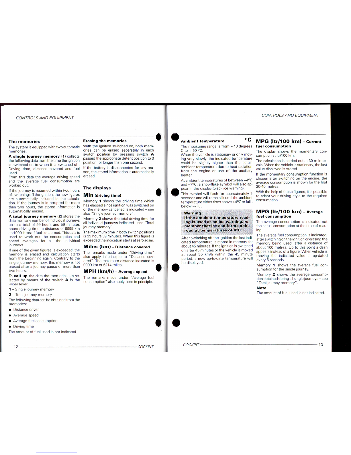
The
memories
The
system is equipped
with
two automatic
memories:
A
single
journey
memory
(1)
collects
the following data from the time the ignition
is
switched
on to
when
it is
switched
off:
Driving time, distance covered
and
fuel
used.
From
this data
the
average driving speed
and
the
average fuel consumption
are
worked out.
If
the journey
is
resumed
within
two hours
of switching off the ignition, the new figures
are automatically included
in the
calcula-
tion.
If the
journey
is
interrupted
for
more
than
two
hours,
the
stored information
is
automatically
erased.
A
total
journey
memory
(2)
stores the
data
from any number of individual journeys
up
to a
total
of 99
hours and
59
minutes
hours driving time, a distance
of
9999
km
and
999 litres of fuel consumed. This data
is
used
to
work
out the
consumption
and
speed
averages
for all the
individual
journeys.
If
one
of
the given figures
is
exceeded,
the
memory
is
erased
and
calculation starts
from
the
beginning again. Contrary
to the
single
journey memory, this memory
is not
erased
after a journey pause
of
more than
two hours.
To
call
up the
data
the
memories are se-
lected
by
means
of the
switch
A in the
wiper lever:
1 -
Single journey memory
2 - Total journey memory
The
following data can be obtained from the
memories:
• Distance driven
• Average speed
• Average fuel consumption
• Driving time
The
amount
of
fuel used
is not
indicated.
Erasing
the
memories
With
the
ignition switched on, both mem-
ories
can be
erased separately
in
each
switch position
by
pressing switch
A
passed
the appropriate detent position
to 0
position
for
longer than one
second.
If the
battery
is
disconnected
for
any
rea-
son,
the stored information is automatically
erased.
The displays
Min
(driving
time)
Memory 1 shows
the
driving time which
has
elapsed since ignition was switched on
or the memory cancelled
is
indicated - see
also
"Single journey memory".
Memory 2 shows the
total
driving time
for
all
individual journeys indicated - see "Total
journey memory".
The
maximum time in both switch positions
is
99 hours 59 minutes. When this figure
is
exceeded
the indication starts at zero again.
Miles
(km)
-
Distance
covered
The
remarks made under "Driving time"
also
apply
in
principle
to
"Distance cov-
ered".
The maximum distance indicated
is
9999
km
or
6214 miles.
MPH
(km/h)
-
Average
speed
The
remarks made under "Average fuel
consumption"
also apply here
in
principle.
12
COCKPIT
CONTROLS
AND
EQUIPMENT
Ambient
temperature
*•*
The
measuring range
is
from - 40 degrees
C
to +
50 °C.
When
the vehicle is stationary or only mov-
ing very slowly,
the
indicated temperature
could
be
slightly higher than
the
actual
ambient temperature due.to heat radiation
from
the
engine
or use of the
auxiliary
heater.
At ambient temperatures
of
between +4°C
and
-7°C, a snowflake symbol will also ap-
pear
in
the display (black ice warning).
This
symbol will flash
for
approximately
5
seconds
and will remain
lit
until
the ambient
temperature either rises above +4°C or falls
below -7°C.
Warning
If the
ambient
temperature
read-
ing
is
used
as an ice
warning,
re-
member
that
ice
can
form
on the
road
at
temperatures
of
4°C.
After switching
off
the ignition the last indi-
cated
temperature
is
stored
in
memory for
about 45 minutes.
If
the ignition is switched
on after 45 minutes or the vehicle is moved
at about
30 km/h
within
the 45
minute
period, a new up-to-date temperature will
be
displayed.
MPG
(Itr/100 km) -
Current
fuel
consumption
The
display shows
the
momentary
con-
sumption
at
Itr/100
km.
The
calculation
is
carried
out at
30 m inter-
vals.
When the vehicle is stationary, the last
value
displayed
is
stored.
If the
momentary consumption function
is
chosen
after switching
on the
engine,
the
average
consumption
is
shown for the
first
30-40 metres.
With the help
of
these figures,
it
is possible
to adapt your driving style
to the
required
consumption.
MPG
(Itr/100 km) -
Average
fuel
consumption
The
average consumption
is
indicated
not
the actual consumption
at
the time
of
read-
ing.
The
average fuel consumption
is
indicated,
after switching on the ignition orerasing the
memory being
used,
after a distance
of
about 100 metres. Up
to
this point a dash
appears
instead
of
a figure. When vehicle
is
moving
the
indicated value
is
up-dated
every 5 seconds.
Memory 1 shows
the
average fuel
con-
sumption
for
the single journey.
Memory 2 shows
the
average consump-
tion
obtained during all single journeys - see
"Total journey memory".
Note
The
amount
of
fuel used
is
not indicated.
COCKPIT
13
www.vwT4camper.info - a useful website for owners and enthusiasts of VW T4 Transporter Campervans

CONTROLS
AND EQUIPMENT
6 -
Selector
lever
position*
dis-
play
The selector lever position for automatic
gearboxes is shown in the display - see
page 117.
7 -
Odometer/
Trip
meter
The upper counter registers the
total
dis-
tance driven and the lower one the short
trips.
The last figure of the lower counter indi-
cates 100 m or V10 mi|e.
The lower counter
(trip
meter) can be
zeroed by pressing the reset knob below
the speedometer.
7 -
Service
interval
Display
(not on TDI or 150 kW
engines)
If a service is clue, one of the following ser-
vices
will
appear in the lower speedometer
counter
(trip
meter) :
• Oil Change Service OIL
• Inspections Service 01
The service display
will
be go out approx.
one minute after the engine has been
switched on. You can also switch back to
the
trip
meter by pressing and holding
(longer than 0.5 seconds) the reset button.
The Volkswagen dealer performing the ser-
vice
will
reset the display.
If the service is not performed by a Volk-
swagen dealer, the display must be reset as
follows:
• With the ignition switched off, press and
hold the
trip
meter reset
button
below the
speedometer.
• Turn the knob to reset the minutes on the
digital clock to the
right,
"service " ap-
pears in the display.
Notes
• Only the desired service may be reset.
The date for a service would otherwise be
incorrect. You can switch between the indi-
vidual services by pressing the reset knob.
• Do not zero the display between the ser-
vice intervals-otherwise an incorrect read-
ing
will
be shown.
• If the vehicle
battery
is disconnected the
details in the service display are retained.
• If a defective speedometer is replaced,
the service interval display must be repro-
grammed. This should be carried out by a
Volkswagen dealer. Should the display not
be reprogrammed, then the service
work
must be carried out in accordance
with
the
Service
Schedule and not according to the
service interval display.
CONTROLS
AND EQUIPMENT
7 -
Variable
Service
interval
Display
(only
for TDI and 150 kW
engines)
3000 km before the next service
work
to be
carried out, the following
will
appear in the
display:
"service km 3000" or
"service in 3000 km".
The kilometre display for the next due ser-
vice
will
go down in steps of 100 km.
If the Service interval has been reached
"service"
or "service now"
will
flash in the
display.
The service display
will
be go out approx. 20
seconds
after the engine has been
switched on. You can also switch back to
the
trip
meter by pressing and holding
(longer than 0.5 seconds) the reset button.
The display
will
then be reset by the Volk-
swagen dealer after the service
work
has
been carried out.
A
print
out of the
work
carried out
will
then
be placed in your vehicle wallet as
proof.
If the service is not performed by a Volk-
swagen dealer, the display must be reset as
follows:
• With the ignition switched off, press and
hold the
trip
meter reset
button
below the
speedometer.
• Turn the knob to reset the minutes on the
digital clock to the
right.
The display
will
then
return
to normal.
Please
note
that
you
cannot
fully
reset
the the
service
display
in
this
way. You can
only
reset
it
back
to
the
15,000
km service.
Notes
• Only the desired service may be reset.
The date for a service would otherwise be
incorrect. You can switch between the indi-
vidual services by pressing the reset knob.
• Do not zero the display between the ser-
vice intervals - otherwise an incorrect read-
ing
will
be shown.
• If the vehicle
battery
is disconnected the
details in the service display are retained.
• If a defective speedometer is replaced,
the service interval display must be repro-
grammed. This should be carried out by a
Volkswagen dealer. Should the display not
be reprogrammed, then the service
work
must be carried out in accordance
with
the
Service
Schedule and not according to the
service interval display.
COCKPIT
15
www.vwT4camper.info - a useful website for owners and enthusiasts of VW T4 Transporter Campervans

CONTROLS AND
EQUIPMENT
Tachograph*
r
r c_o|
;
86.85.88
15:88
[ © 436.8
km h t
CD
( ) ( )
CZD
i
I
B7D-159K
|
Factory-installed tachographs
are
supplied Details
of the
regulations
can be
obtained
with a supplementary instruction manual. from local vehicle licensing authorities.
When service installing a tachograph,
please refer
to the
instructions
in
Booklet
3.2 under "Accessories, modifications
and
replacement
of
parts".
In
many European countries the installation
and
use of
a tachograph
is
obligatory for the
following
vehicles:
1 - Vehicles used
for
the commercial trans-
port
of
goods with a permissible total
weight including trailer
or
articulated
trailer
of more than
3.5
tons.
It is
imma-
terial
whether the vehicle and the trailer
or only one
of
the two
is
used for
com-
mercial goods transport.
2 - Vehicles which according
to
their
de-
sign
and equipment are suitable for and
intended to carry more than 9 persons
including the driver.
16
COCKPIT
CONTROLS AND
EQUIPMENT
Warning
and
indicator
lamps
©
((D)
©
©
EPC
©
O
©
Q
©
©
^6
V-/
CHECK
©
fll
©
©
<>10
©
w
©
(S>
©
(®)
©
Qi
©
ID
©
(©)
®
©
ft
[B7D-161KJ
The layout and number
of
the
warning
and
indicator lamps in the combi-instrument de-
pend
on:
-
the
version
of
the engine and conditions
specific to a particular country
as
well
as
-
the
equipment you have selected and
its
possible combinations.
The symbols
on the
warning
and
indicator
lamps can only be seen when the lamps are
illuminated.
The figure illustrates all warning and indica-
tor
lamps.
Warning
lamps
(light
up in red)
Pos.
Page
1 - Brake system/handbrake
on
18
2 - Alternator
18
3 - Seat
belt
18
4 - Handbrake
on
19
5 - Coolant temperature/
coolant level
19
6 - Engine
oil pressure
20
Indicator lamps
(light
up in yellow, green or blue)
Pos.
Page
7 - Engine
oil level
20
8- Trailer turn
signals
21
9 - Rear fog light
21
10 -
Turn
signals
21
11 - Engine
management (petrol engine)21
12 - Exhaust
emissions warning lamp
. 21
13 - Diesel engine
-
Glow plug system
21
-
Engine
malfunction
21
14 - Main
beam
21
15 - Airbag system
22
16 - Brake wear monitor
22
17-Low fuel
22
18 - Electronic Stability
Programme
22
19 - Anti-lock brake system
23
COCKPIT
17
www.vwT4camper.info - a useful website for owners and enthusiasts of VW T4 Transporter Campervans

CONTROLS
AND
EQUIPMENT
1 -
Brake
system/ (rj))
handbrake
on
The
warning lamp comes on when
• the handbrake is on
• the brake fluid level is too low
The
ignition must be switched on.
In addition, a warning signal will sound on
some
models if the vehicle is driven at
speeds
higher than 6 km/h with the hand-
brake
on.
The
brake system warning lamp does not
come
on when the handbrake is on for ve-
hicles
with a separate warning lamp for
handbrake
on.
Warning
If the
warning
lamp
does not go
out
after
the
handbrake
is re-
leased or comes on
while
the ve-
hicle is being driven, the
brake
fluid
level
in the reservoir is too
low. Stop the vehicle, do not
drive
on and call for
expert
as-
sistance.
If the
brake
system
warning
lamp
and the ABS indicator
lamp
are
both
on, the
regulating
function
of the ABS may
have
failed. The
rear
wheels
may block
when
the
brakes
are applied. This could
possibly
lead
the
rear
of the ve-
hicle to skid.
Drive
carefully
to the
next
Volk-
swagen
dealer
and
have
the
fault
corrected.
2 -
Alternator
Q
The
warning lamp comes on when the igni-
tion is switched on. It must go out when the
engine
starts.
The
alternator is driven by a long-life ribbed
belt.
If the warning lamp lights during the
journey, stop,
switch
off
engine
and
check
ribbed belt.
Warning
Please
refer
to the
warning
notes
on
page
60
before
carrying out
any
kind
of
work
in the
engine
compartment.
If the warning lamp comes on although the
V-belt
or ribbed belt is not broken or loose,
one
can normally drive on to the nearest
Volkswagen
dealer.
As
the battery will continue to
discharge,
all
electrical
consumers which are not
abso-
lutely necessary should be switched off.
The
ribbed belt should be checked by a Volk-
swagen
dealer and changed if necessary.
3 -
Seat
belt
*,
warning
lamp* /rr
The
warning lamp lights up (only for certain
countries) for about 6 seconds after ignition
as
a reminder to fasten your safety belt.
If the seat belt is not fastened an acoustic
signal
will sound after switching on the igni-
tion which will stop after 6
seconds
or when
the seat belt is fastened.
Please
refer
to
chapter
"Seat
belts" in Booklet 2.1.
8
COCKPIT
CONTROLS
AND
EQUIPMENT
4 -
Handbrake
on*
When
the
handbrake
is pulled on and
the ignition is switched on, the warning
lamp will light up. It must go out when the
handbrake
is released.
In addition, a warning signal will sound on
some
models if the vehicle is driven at
speeds
higher than 6 km/h with the hand-
brake
on.
If the warning lamp does not go out al-
though coolant level and fan fuse are in
order, do not
drive
on - call in expert as-
sistance.
If the trouble is only caused by the fan and
assuming
coolant level is in order and tem-
perature warning lamp is out - one can drive
on to the nearest Volkswagen dealer. In
order to make good use of the air stream for
cooling,
do not let engine idle or drive very
slowly.
5 - Coolant
temperature/
Coolant
level
The
warning lamp lights up for a few
sec-
onds
as a functional check when ignition is
switched
on.
If the lamp does not go out afterwards or
lights up or flashes when driving, either the
coolant
temperature is too high or the
cool-
ant level too low. An acoustic signal will
sound
3 times as an additional warning:
Stop,
switch
engine
off and check
level.
Add coolant if necessary. The type of
coolant
to be filled can be found in Booklet
3.2,
"Cooling system".
Warning
Please
refer
to the
warning
notes
on
page
60
before
carrying out
any
kind
of
work
in the
engine
compartment.
If the coolant level is satisfactory the trouble
may
be due to a failure of the radiator fan.
Check
radiator fan fuse and renew if
necessary.
Warning
notes
• Please
note
the
following
points to
prevent
scalding by hot
coolant:
- Exercise caution
when
open-
ing the coolant expansion
tank!
When
the
engine
is hot
the cooling system is under
pressure -
Danger
of scalding!
Therefore
let
engine
cool
down
before
unscrewing the
cap!
- To
protect
the face, hands and
arms
you should cover the cap
of the
radiator
with a large,
thick
cloth to
offer
protection
against
steam
or hot fluid.
• Please ensure
that
the coolant
does not
drip
on the hot
exhaust
or
other
hot
engine
components.
The
frost
protection
agent
in-
cluded in the coolant could ig-
nite.
COCKPIT
19
www.vwT4camper.info - a useful website for owners and enthusiasts of VW T4 Transporter Campervans

CONTROLS
AND EQUIPMENT
CONTROLS
AND EQUIPMENT
6 - Engine oil pressure
The
warning lamp lights up for a few
sec-
onds
as a functional check when ignition is
switched on.
Lights up or flashes red
(engine
oil pressure too low)
If the warning lamp does not go out, an
acoustic
signal will sound 3 times as an
additional warning. Do not
start
the en-
gine! Check oil level and if necessary, add
oil.
Warning
Please
refer
to the
warning
notes
on
page
60
before
carrying
out
any
kind
of
work
in the
engine
compartment.
If the warning lamp comes on or flashes
when driving - an acoustic signal sounds
three times as an additional warning at en-
gine speeds above 1500 rpm. Stop,
switch
engine
off! Check oil level and if
necessary,
add oil - see Booklet 3.2.
If the lamp flashes although the oil level is
in order, do not
drive
on. Do not even run
the engine at idling speed - call in expert as-
sistance.
If during the journey the engine is operated
at a speed less than idling
speed,
it can
happen
that
the oil pressure warning lamp
lights up. Increase engine speed by acceler-
ating or changing down.
The oil pressure
warning
lamp
is not
an oil
level
indicator!
The oil
level
should
therefore
be checked at reg-
ular
intervals,
preferably
every
time
the
fuel
tank
is
filled.
7 - Engine oil
level
4
•
Lights up
yellow
(Engine
oil
level
too low)
If the indicator lamp lights up yellow.the en-
gine oil level is probably too low. At the
same
time the warning
"CHECK
OIL
LEVEL"
appears briefly in the on-board
computer* display.
Check
the oil level the next time you
fill
up
the tank at the latest and to up
with
engine
oil if necessary - see Booklet 3.2., "Engine
oil".
^
Warning
•
Please
refer
to the
warning
notes
on
page
60
before
carrying
out
any
kind
of
work
in the
engine
compartment.
The
oil level warning will be deleted when
the bonnet is opened. The warning will be
shown again after approx. 100 km if no oil is
refilled.
Flashes
yellow
(Engine
oil
level
measuring
device
is
defective)
The
warning lamp will start to flash and an
acoustic
signal will sound if the engine oil
level
measuring device is defective.
At the same time the warning "OIL SEN- A
SOR
WORKSHOP"
appears briefly in the •
display
of the on-board computer*. The en-
gine should be checked by a Volkswagen
dealer
as soon as possible.
The
oil level
must
be checked regularly,
preferably when filling up petrol, in the
period between the defect warning and the
engine check.
8 -
Trailer
turn
signals
The
warning lamp* flashes when
turn
sig-
nals
are switched on when towing a trailer.
If a
turn
signal fails on the trailer or vehicle,
the warning lamp does not flash.
9 -
Rear
fog
light*
0$
The
warning lamp lights up when the rear
fog light is switched on. For further details
see
page 61.
I
10-Turn
signals <^c>
The
right
or
left
arrow will flash depending
upon which direction has been selected. If
a
turn
signal fails, the warning lamp flashes
twice as fast. (Not when towing a trailer).
Further details are given on pages 21 and
64.
11- Engine
management
system EPC
(petrol engine only)
The
warning lamp comes on when the igni-
tion is switched on and must go out when
the engine is started.
If a fault occurs in the engine management
system
during the operation of an 85 or 150
kW
petrol engine, it will be indicated by the
indicator lamp flashing. The engine must be
checked
as soon as possible by a Volk-
swagen
dealer.
12- Exhaust emission
CHECK
warning
lamp*
K2D
(petrol engine only)
Blinks: If the catalyst can be damaged by
misfires.
Lights up: If a fault which reduces the
quality of the exhaust gas (e.g. a Lambda
probe
fault)
occurs during a drive.
Let
off on the accelerator, drive carefully to
the next Volkswagen dealer and have the
engine checked.
13- Glow plugs
Tffi
(Diesel
engines only)
When
the engine is cold the warning lamp
comes
on when key is turned to Drive
posi-
tion (ignition on).
If the warning lamp does not come on when
the engine is cold, there is a defect in the
glow plug system - call in expert assist-
ance.
When
the lamp goes out, start the engine
immediately - see page 124.
When
the engine is
warm
the glow plug
lamp does not come on - the engine can be
started straight away.
Engine
faults*
W
If while driving a fault occurs in the diesel
engine management system on a 65, 75 or
111 kW diesel engine, this is indicated by
the warning lamp flashing. The engine must
be
checked as soon as possible by a Volk-
swagen
dealer.
14
-Main
beam
ID
The
warning lamp comes on when main
beam
is on or when the headlight flasher is
used.
20
COCKPIT
COCKPIT
21
www.vwT4camper.info - a useful website for owners and enthusiasts of VW T4 Transporter Campervans

CONTROLS
AND
EQUIPMENT
CONTROLS
AND
EQUIPMENT
15 -Airbag system* 59
The
warning lamp lights up for a few
sec-
onds
when the ignition is switched on. On
vehicles
with
the passenger-side air-
bag
deactivated
the warning lamp will
then flash for approximately 12 seconds
(see
Booklet 2.1 under "Deactivating air-
bags").
If the warning lamp does not go out after the
given period, or if it lights up, flashes or
flickers during a journey, there is a
fault
in
the airbag system. The system should im-
mediately be checked by a Volkswagen
dealer.
•
16 -Brake
wear
monitor*
o
The
warning lamp will
light
up when the
brakes
being monitored have reached the
wear level.
You
should contact a Volkswagen dealer im-
mediately so
that
the brake pads/linings can
be checked.
The
brake wear monitor checks the
front
left
and the rear
right
brake. If the display
lights up we recommend
that
the other
brakes
be checked as well.
On
vehicles
with
a 16" running gear, the
brake pad wear monitor checks the brake
pads
on all four wheels.
17 -Fuel reserve*
The
warning lamp comes on when there an
I
approximately 10 litres
left
in tank. A wain
ing signal will also sound.
18 -Electronic
Stability
Programme (ESP)*
The
warning lamp lights up upon ignition
and should go out after approx, 2
second:.
The
ESP
unit
also has Traction Control Sya
tern
(TCS).
i
The
lamp flashes when the system is in
operation whilst the vehicle is in motion.
When
the
unit
is switched off or if them la
a
fault
in the system, the warning lamp la
permanently on.
As
the
ESP
unit
functions together
with
111<
<
ABS
and EDL, the ABS warning lamp will
also
come on if the ESP fails.
For
further notes please refer to page 129
1U /Villi locking
brake
m
(ABS)* <W
[In ii i lamp monitors the ABS and
||>l *
irii'..
A.
Brake System (ABS)*
f|i
H
i
MI K i
lamp comes on for a few sec-
'ii
i in n
11
HI
ignition is switched onorthe
MinM>> i ilml
I
ho lamp goes out after an
|l in
11".i
sequence has been com-
|iii i ' i
||
II i.-. n/iiming lamp does not come on
|
i in ignition is switched on, does not
i
HI.
i>i i
iimos
on when driving, the sys-
|»n i I.n illy.
/\ - ill
III
ilii)
ABS is indicated as follows:
•
Air.
w.lining,
lamp lights up The ve-
i
' nil I II : braked
with
normal braking
i.
without
ABS. A
Volkswagen
i
< i
nil
ill I however bo consulted as
ail
,i |iu.',:;it)lo.
9 ii Alls
w.lining
lamp lights up to-
U<
Hi.
i ninth brake system warning
i,,.. ,. , .! miiy is the ABS system defec-
ii
hnl a change braking characteristics
Imn
ii
111H • expected.
•
Warning
If
both
the ABS
indicator
lamp
and the
brake
system
warning
lamp
light
up, you
must
stop the
vehicle
immediately
and check
the
brake
fluid
level. If the
fluid
level
is
below
the "MIN"
mark,
do not
drive
on. Please ask for ex-
pert
assistance.
If the
brake
fluid
level
is at a
sat-
isfactory
level, the
fault
might
stem
from
the ABS. The
rear
wheels
can block
relatively
quickly
if the
regulating
function
of the ABS
fails.
This could poss-
ibly
lead
the
rear
of the
vehicle
to
skid.
Drive
carefully
to the
next
Volk-
swagen
dealer
and
have
the
fault
corrected.
Further details on ABS are given in Booklet
3.2.
under "Braking".
Electronic
Differential
Lock
(EDL)*
The
EDL system works in conjunction
with
the
ABS.
Failure of the EDL system is indi-
cated by the ABS warning lamp lighting up.
This
lamp will also
light
up if the TCS and
ESP
should fail. The vehicle should be taken
to a Volkswagen dealer as soon as possible.
Further details on EDL can be found in
Booklet 3.2.
www.vwT4camper.info - a useful website for owners and enthusiasts of VW T4 Transporter Campervans

I*
I
SEEUEG
PRNS321
CONTROLS
AND
EQUIPMENT
Navigation system*
pressing the button A in the wiper/washer models only - see figure,
lever (for longer than 2 seconds): Driving information of all other vehicles ap-
- Navigation display
Pears
in tne navigation system display
field.
- Multi-function display The operation of the Volkswagen navigation
system is detailed in a separate supple-
ment.
When the navigation system or multi-func-
tion indicator are in use, any faults that may
occur will be shown with priority in the dis-
play via the on-board computer - as of page
•
CONTROLS
AND
EQUIPMENT
On-board computer with Multi-function indicator*
Only on vehicles with a navigation
system*
The on-board computer constantly checks
certain functions and vehicle components
for their condition when the ignition is on
and also when the vehicle is in motion.
These displays show the display of the
multi-function indicator and the on-board
computer. The functions and displays of the
multi-function indicator are detailed on page
10.
i
Any faults in the function or any urgent re-
' pairs or service requirements will be
indi-
cated via an acoustic signal and, according
to priority, displayed through red and yellow
symbols in the combi instrument.
Furthermore, information texts will be
shown in the display as an additional aid for
the driver to the red and yellow symbols.
The information texts shown in the il-
lustrations of this Owner's Manual are in
German.
The information texts and
driver's notes will appear in the following
languages according to the country:
English,
French, Italian, Spanish, Portu-
guese and Czech.
Function check
Vehicles with manual gearbox
If there are any faults, these will be dis-
played after turning on the ignition. At the
same time, the appropriate acoustic warn-
ing signal will sound:
Vehicles with automatic gearbox
After switching on the ignition, the follow-
ing driver's note appears in the display
when the selector lever is in position"P"
and "N":
"APPLY FOOT BRAKE WHEN SELECTING
GEAR WITH VEHICLE STATIONARY".
This note will disappear when a driving
range is selected ("R","D"
etc.).
If there are one or more faults, the driver's
note will disappearapprox. 15 seconds after
starting the engine and a fault symbol with
the appropriate information text will appear
in the display
field.
For all vehicles:
If there is a fault an acoustic warning signal
will also sound:
- Priority 1 - three warning tones
- Priority 2 - one warning tone.
Three warning tones will sound if faults of
Priority 1 and 2 are present.
If there is a fault, the symbol will appear
with the appropriate information text.
Note
Faults of Priority 2 will not be displayed
until Priority 1 have been repaired or cor-
rected!
COCKPIT
25
www.vwT4camper.info - a useful website for owners and enthusiasts of VW T4 Transporter Campervans

CONTROLS
AND EQUIPMENT
Priorit y
1 (Red symbols)
These Priority 1 symbols imply
danger.
For this reason you must
stop
the vehicle and switch off the
engine!
Repair
the
fault.
Expert
help
might
be
needed.
If
there
is
more
than
one
fault
of
Priority
1
the
symbols
will
appear
one
after
the
other
for
two
seconds
at a time.
The
symbols
will
flash
until
the
fault
has
been
corrected.
The
following
faults or
warnings
of
priority
1
can be
displayed:
Engine oil pressure
The
information
note
says:
"STOP!
OIL PRESS.
STOP
MOTOR!
SERVICE
MANUAL".
If
this
symbol
flashes
when
driving,
stop,
switch engine off.
Check
oil
level
and
if
necessary,
add oil - see
Booklet
3.1, "En-
gine
oil".
Warning
Please
refer to the warning notes
on
page 60 before carrying out
any kind of work in the engine
compartment.
If the
symbol
flashes
although
the oil
level
is
in
order,
do not drive on.
Do
not
even
run
the
engineat
idling
speed-call
in
expert
assistance.
The oil pressure warning lamp is not
an oil level indicator! The oil level
should
therefore be checked at reg-
ular intervals, preferably every time
the fuel tank is filled.
Brake system (©)
This
symbol
can
monitor
up to
three
func-
tions
at
one
time:
1 - Brake fluid
The
information
note
says:
"STOP!
BRAKE FLUID
SERVICE
MANUAL".
This
symbol
comes
on
when
the
brake
fluid
level
is
too
low.
Stop
vehicle and check brake fluid
level.
Warning
Please
refer to the warning notes
on
page 60 before carrying out
any kind of work in the engine
compartment.
Warning
If the brake fluid level in the
res-
ervoir has fallen below the
"MIN"
level, do not drive on.
Please
call for expert
assistance.
If the brake fluid level is satisfac-
tory,
the fault might stem from
the ABS. The rear
wheels
can
block
relatively quickly if the
regulating
function of the ABS
fails. This could possibly lead the ,
rear of the vehicle to skid.
Drive carefully to the next Volk-
swagen dealer and have the fault
corrected.
26
COCKPIT
CONTROLS
AND EQUIPMENT
2 - ABS and EDL* system
The
information
note
says:
"STOP!
BRAKE FAULT
SERVICE
MANUAL".
If the brake system warning lamp
flashes whilst the ABS warning
lamp
is lit up,
not
only
is
the
ABS
system
defective,
but you
must
also
expect
the
brake
system
to
respond
differently
to the
normal
response.
Warning
Please
refer to the warning notes
on
page 60 before carrying out
any kind of work in the engine
compartment.
Warning
If both the ABS indicator lamp
and
the brake system warning
lamp
light up, you must stop the
vehicle immediately and check
the brake fluid level. If the fluid
level is below the "MIN" mark,
do
not drive on.
Please
ask for ex-
pert
assistance.
If the brake fluid level is at a
sat-
isfactory level, the fault might
stem from the ABS. The rear
wheels
can block relatively
quickly
if the regulating function
of
the ABS fails. This could poss-
ibly
lead the rear of the vehicle to
skid.
Drive carefully to the next Volk-
swagen dealer and have the fault
corrected.
Further
details
on
ABS are
given
in
Booklet
3.2.
under
"Braking".
The
EDL
system
works
in
conjunction
with
the
ABS. Failure of the EDL
system
is
indi-
cated
by the ABS
warning
lamp
lighting
up.
This
lamp
will
also
light
up if the TCS and
ESP
should
fail.
The
vehicle
should
be
taken
to a Volkswagen
dealer
as
soon
as
possible.
3 - Handbrake*
The
information
note
says:
"HANDBRAKE
ON".
.
When
the handbrake is pulled on and
the
ignition
is
switched
on, the
warning
lamp
will
light
up. It
must
go
out
when
the
handbrake
is
released.
If it
does
not,
there
is a fault
in the
brake
system.
A
warning
signal
will
sound
if the
vehicle
is
driven
at
speeds
higher
than 6 km/h.
COCKPIT
27
www.vwT4camper.info - a useful website for owners and enthusiasts of VW T4 Transporter Campervans

CONTROLS
AND
EQUIPMENT
Coolan t
temperature/ t
coolant
level ~fr
The
information note
says:
"STOP!
CHECK
COOLANT
SERVICE
MANUAL".
If this
symbol
lights up or
flashes
when
driv-
ing,
either the
coolant
temperature is too
high
or the
coolant
level
too low:
Stop,
switch engine off and
check
level.
Add
coolant
if
necessary.
Warning
Please
refer to the warning notes
on
page 60 before carrying out
any kind of
work
in the engine
compartment.
If the
coolant
level
is
satisfactory
the trouble
may
be due to a failure of the radiator fan.
Check
radiator fan
fuse
and
renew
if
necessary.
If the warning
lamp
does
not go out al-
though
coolant
level
and fan
fuse
are in
order,
do not drive on -
call
in expert as-
sistance.
If the trouble is
only
caused
by the fan and
assuming
the
coolant
level
is OK and the
text
in the
display
has
disappeared
- one
can
drive on to the
nearest
Volkswagen
dealer.
In
order
to
make
good
use of the air
stream
for
cooling,
do not let
engine
idle
or
drive
very
slowly.
Please
refer to
Booklet
3.2.
under
"Coolant
system"
for further
information.
Warning notes
•
Never open the bonnet if you
can
see steam or coolant coming
from the engine compartment -
Risk
of scalding!
Wait
until no
more steam or coolant can be
seen..
•
Do not touch the fan. The fan
can
switch on suddenly - even
when ignition is switched off.
•
Please note the following
points
to prevent scalding by hot
coolant:
-
Exercise caution when open-
ing
the coolant expansion
tank!
When the engine is hot
the cooling system is under
pressure
- Danger of scalding!
Therefore let engine cool
down before unscrewing the
cap
I
-
To protect the face, hands and
arms you should cover the cap
of the radiator
with
a large,
thick cloth to protect against
steam or hot fluid.
•
Please ensure
that
the coolant
does
not drip on the hot exhaust
or
other hot engine components.
The
frost protection agent in-
cluded
in the coolant could ig-
nite.
28
COCKPIT
CONTROLS
AND
EQUIPMENT
Priority
2 (Yellow symbols)
If a
yellow
symbol
appears
one warning
signal
will
sound.
The
symbols
are a warn-
ing.
The function
displayed
should
be
checked
as
soon
as
possible.
If there is
more
than
one
warning,
the
symbols
will ap-
pear
one after the other for
approx. 2 sec-
onds
at a time.
Brake lining worn* (O)
The
information note
says:
"CHECK
BRAKE
LINING"
You
should
contact a Volkswagen
dealer
so
that
the
brake
pads/linings
can be
checked.
The
brake
wear
monitor
checks
the front
left and the
rear
right
brake.
If the
display
lights
up we
recommend
that the other
brakes
be
checked
as
well.
On
vehicles
with a 16" running
gear,
the
brake
pad
wear
monitor
checks
the
brake
pads
on all four
wheels.
Fuel
low •—1
The
information note
says:
"FILL
TANK"
Fill
vehicle
tank as
soon
as
possible
- see
page
130.
Engine
oil level measuring device*
defective
The
information note
says:
"OIL
SENSOR
WORKSHOP"
The
oil
sensor
is
probably
defective
if the
symbol
flashes.
You
should
go to a
Volk-
swagen
dealer
as
soon
as
possible.
You
can
continue
driving,
but
should
check
the oil
level
regularly,
preferably
when
filling up
with
petrol.
Warning
Please
refer to the warning notes
on
page 60 before carrying out
any kind of
work
in the engine
compartment.
Engine
oil level* too low ty.
The
information note
says:
"CHECK
OIL
LEVEL"
If the
symbol
appears,
check
the oil
level
the
next
time you fill up the tank and top off en-
gine
oil if
necessary
-see
Booklet3.2,
"En-
gine
oil".
Warning
Please
refer to the warning notes
on
page 60 before carrying out
any kind of
work
in the engine
compartment.
COCKPIT
29
www.vwT4camper.info - a useful website for owners and enthusiasts of VW T4 Transporter Campervans

CONTROLS
AND
EQUIPMENT
Mobil e
telephone
•
Mounting
for
mobile
telephone*
The
mobile telephone is
fitted
to an adapter
for use in the vehicle whilst stationary. In
this way, all the advantages of a regular car
telephone (hands-off equipment, optimum
transmission
through exterior aerial etc.)
can
be employed to the full. The recharge-
able
battery of the telephone is also
con-
stantly recharged.
To
telephone
without
the
hands-free
system you must
lift
the
mobile
tele-
phone
including
telephone
adapter
out of the retainer:
To
take out. the telephone, hold it
tightly
and
press
the button 1 at the same time.
Once you
have
taken
out the
mobile
telephone
with
the
telephone
adapter,
do not speak as
normal
into
the
mobile
telephone,
but
rather
into
the
rear
side of the
telephone
adapter!
Feedback could
otherwise
occur.
Removing
mobile
telephone
The
mobile telephone can be taken out of
the telephone adapter for use outside of the
vehicle.
Hold
the telephone and press button 2 at
the same time - the mobile telephone can
now be taken out.
Warning
Please
concentrate
on your
driv-
ing
above
all!
Replacing
mobile
telephone
Place
telephone in the adapter and push it
to the
front
until it engages at the top.
Notes
The
function of the Volkswagen mobile tele- •
phone is detailed in a separate supplement ™
to this manual.
Please
read
the
notes
in
Booklet
3.2,
"Mobile
telephones
and
two-way
ra-
dios".
•
30
-
COCKPIT
Hands-free
system for
mobile
telephones*
CONTROLS
AND
EQUIPMENT
Provision for
telephone*
With the hands-free system, it is possible to
telephone without having to take the mobile
telephone in your hand.
If you receive a telephone
call,
the voice of
your conversation partner will be relayed
over
the speakers of the radio system. You
have
nothing further to do when respond-
ing;
you simply react as if you were talking
to a passenger in the vehicle.
The
desired conversation
volume
can
be
set via the radio. Furthermore, it is
necessary
to set the listening volume of the
mobile telephone once.
The
operation of the units is described in a
separate
manual.
Take
the
mobile
telephone
with
you
when
leaving
the
vehicle
or
switch
off the
automatic
call acceptance
function
as calls could
otherwise
be
put
through
even
when
the
radio
is
switched
off.
The
provision for a telephone is made up of:
• a microphone (between the wind-
shield
and the driver's door),
• the automatic loudspeaker switch-
over
of the radio system (for amplifying the
conversation)
• and a combined
radio/telephone
roof
antenna
Furthermore, the connecting cables for
the
interface
box are under the centre
console.
You
will
also
need
the
following
in
order
to be to
telephone:
• an
interfacebox
• a
mobile
telephone
retainer
Both parts must be suitable in
size
for the
mobile telephone!
COCKPIT
31
www.vwT4camper.info - a useful website for owners and enthusiasts of VW T4 Transporter Campervans

CONTROLS
AND
EQUIPMENT
Keys
I
B7D-160K
The vehicle
is
supplied with
two1)
main
keys A and one emergency key B which
fit
all locks.
We recommend that you keep
the
emerg-
ency key separate from the vehicle registra-
tion papers. The emergency key should only
be used temporarily.
Warning
• Always withdraw
key
from
ignition whenever
you
leave
the
vehicle - even
if
only
for a
short
time. This
is
particularly import-
ant
if
children
are to
remain
in
the vehicle. They could other-
wise start
the
engine
or
electrics
- e.g. electric windows.
Risk
of
accident!
•
Do not
withdraw key from lock
until vehicle
is
stationary!
The
steering lock could
be
uninten-
tionally engaged.
11 Four keys
are
provided
in
some export
markets.
Notes
Every
key
contains electronic com-
ponents! Protect
the
keys from
moisture
and
hard jolts.
Vehicles equipped with radio-wave remote
control have
two
radio-wave keys and
one
emergency key. Further notes on the effec-
tive range
and the
function
of the
radio-
wave
key
can
be
found from page
42 on-
wards.
A further
key is
provided
for
each
of the
items listed below. These keys will also only
fit
the
appropriate lock:
• lockable stowage area* in the dash panel
on
the
front passenger side
• lockable stowage area*
in the
left door
trim.
Replacement keys
For reasons
of
security, replacement
keys
are
only available from Volk-
swagen dealers.
Key
tag
The
key
number, which
is
needed
to
obtain
replacement keys,
is
located on the key
tag
C. Volkswagen dealers
can
only order
re-
placement keys
if
they have this number.
The
key tag
should
be
kept separ-
ately
as
keys
can
only
be
replaced
using these numbers.
If you sell
the
vehicle,
you
should also give
the buyer this key tag.
32
OPEN
AND
CLOSE
CONTROLS
AND
EQUIPMENT
Electronic immobilizer
The immobilizer prevents unauthorized per-
sons using your vehicle.
A micro-chip
is
located
in the
head
of the
key which automatically deactivates the im-
mobilizer when
the key is
inserted
in the
ignition lock.
The system is automatically activated when
the ignition
is
switched
off.
The engine
can
thus only
be
started
with a correctly coded Genuine
) Volkswagen
key.
Trouble free operation
of
your
ve-
hicle
can
only
be
guaranteed when
using genuine keys.
Security locking*
(only
for
special vehicles)
A further
key is
provided
for
each
of the
items listed below. These keys will also only
fit
the
appropriate lock:
You can lock and unlock the locks
of
the
slid-
ing door and the tailgate
or
wing doors only
with
the
security key. The main and emerg-
ency keys
do not fit
these locks.
©
j B1H-087C]
Key with built-in light*
There
is a
built-in light
in one of the two
keys.
To
switch
the
light
on,
press
the
centre
of the
key (arrow
1).
To change battery
or
bulb
• Insert a coin in the slot
at
the side
of the
key (arrow
2)
and lever
the
upper part
off.
• Change battery
or
bulb.
Spare batteries and bulbs
can be
obtained
from Volkswagen dealers.
cQa
The
flat battery should
be
clis
posed
of
with
due
respect
for the
environment
OPEN
AND
CLOSE
33
www.vwT4camper.info - a useful website for owners and enthusiasts of VW T4 Transporter Campervans

CONTROLS
AND
EQUIPMENT
Door s
Cab doors
When closing doors, always hold the door
handle.
From outside, the front doors can be
locked or unlocked only with the main or
emergency key.
When unlocking, the locking knobs move
up.
When locking, the locking knobs move
down.
The front passenger door can be locked
from outside without using the key: Just
press locking knob down and close door.
The driver's door cannot be locked when
open by pressing the locking knob down
and closing door. This prevents you from
leaving the key in the car and forgetting it.
From inside all the doors can be locked by
pressing down the locking knobs.
As long as the knobs are pressed down the
doors cannot be opened from inside or out-
side.
Warning
Locked doors prevent persons
from entering the car forcibly
e.g.
at traffic lights. They make it
more difficult, however, for out-
side help to open the doors in an
emergency.
Sliding door
Child-proof lock on sliding door
When the child-proof catch is engaged -
lever on door lock down - the inner lock re-
lease lever is inoperative. The door can only
be opened from outside with the locking
knob in the up position.
From outside, the sliding door can bo
locked or unlocked with the main or emerg-
ency key.
See the instructions on page 33 for vehicles
with security locking*.
The sliding door can also be locked from
outside without using the key: Press locking
knob down and close door.
From inside, the sliding door is locked by
pushing down the locking knob.
As long as the knob is pressed down the
door cannot be opened from inside or out-
side.
•
•
34
OPEN
AND
CLOSE
CONTROLS
AND
EQUIPMENT
When the vehicle is moving, the door must
always be properly closed, but when carry-
ing passengers the locking knob should be
left in the upper position so that the door can
be opened from outside in an emergency,
in the fully opened position the sliding door
is hold open by a retainer.
Warning
• Never open the sliding door
when the vehicle is in motion -
Risk of injury!
• The sliding door can, if held
open by the retainer, close unex-
pectedly if the vehicle is parked
on an incline and the door is acci-
dentally knocked when entering
- Risk of injury!
• If the sliding door is opened in-
attentively or hastily with the
wing doors* fully open to an
angle of 265°, there is a risk of
substantial injury or damage to
the vehicle.
OPEN
AND
CLOSE
— 35
www.vwT4camper.info - a useful website for owners and enthusiasts of VW T4 Transporter Campervans

CONTROLS
AND
EQUIPMENT
Wing
doors'
Warning
•
Do not
close
the
wing doors
with your hand
on the
window.
The glass could shatter - Risk
of
injury!
• After closing
the
wing doors,
always pull
on
them
to
make sure
that they
are
properly closed
-
otherwise they could open
suddenly when vehicle
is
mov-
ing,
even though
the key has
been turned
in the
lock.
• Never drive with slightly
or
even fully open wing doors
as ex-
haust
gas
will otherwise
be
drawn into
the
vehicle interior!
Danger
of
asphyxiation!
Right-hand wing door
On some model versions,
it is
necessary
to
swing
the
spare wheel bracket
to the
right
before opening
the
tailgate
- see
Booklet
3.2, "Vehicle tools, spare wheel".
From outside,
the
wing door
can bo
locked
or
unlocked with the main
or
emerg-
ency key. When
the
door
is
unlocked,
the
locking knob goes up; when locked,
it
goes
down.
See the instructions on page 33 for vehicles
with security locking*.
Unlocking
Turn
key to
position
1 and
operate door
handle.
Locking
Turn key
to
position
2.
<
36
OPEN
AND
CLOSE
CONTROLS
AND
EQUIPMENT
~—r—\
\
1
ri
0
|_B70-597C
From inside
the
door
is
locked
by
pres-
sing down
the
knob
(A).
As long
as the
knob
is
pressed down
the
door cannot
be
opened from inside
or
out.
To open the door lift the lever in the direction
in direction
of
arrow.
In
the
fully open position (approx. 90°)
the
door
is
held
by a
check strap.
Child-proof lock
on
wing door
When
the
child-proof lock
is
engaged
-
lever on door lock down - the inner lock
re-
lease lever is inoperative. The door can only
bo opened from outside with
the
locking
knob
in the up
position.
Please also refer
to the
further
notes
on
next page.
OPEN
AND
CLOSE
37
www.vwT4camper.info - a useful website for owners and enthusiasts of VW T4 Transporter Campervans

CONTROLS
AND EQUIPMENT
Left-hand
wing door
The left-hand door can be opened when the
right-hand door
is
open.
To
open,
pull release lever
as
far
as
stop
in
direction
of
arrow.
In the
fully open position (approx. 90°)
the
door
is
held
by
a check strap.
•
When closing the wing doors al-
ways ensure that the left-side door
is closed first.
Warning
See warning concerning tailgate
on
page 36.
Unhooking
door
check
strap
Both doors
are
held
in the
open position
{approx.
90°)
by
check straps. To open
the
doors further the check straps
can be un-
hooked
To unhook swing door inwards slightly, until
check strap slides out
of
retainer and then
pull
check strap inwards.
The wing doors are not held open in the fully
open position (approx.
180°).
When
doors are closed the check straps en-
gage
again
automatically.
Note
In
the fully open position,
the
wing doors*
with
an opening angle of
265°
are held onto
the side panel with magnets.
^
•
38
OPEN
AND
CLOSE
CONTROLS
AND EQUIPMENT
lailgate
On some model versions, it
is
necessary to
swing the spare wheel bracket
to
the right
before opening
the
tailgate
- sec
Booklet
3.2, "Vehicle tools, spare
wheel".
The tailgate lock can
be
locked
or
unlocked
with
the main
or
emergency
key.
See the instructions on
page
33 for vehicles
with
security locking*.
Warning
When a luggage
carrier is fitted
to
the tailgate (e.g. for
bicycles)
you
should note that the tailgate
might not open fully or might
drop
back of its own accord due
to
the extra
load.
In this case, before loading the
luggage
area, support the tail-
gate separately or remove the
baggage
from the carrier.
Risk
of injury!
To open
the tailgate when
key
slot
is
hori-
zontal,
pull the release behind the trim strip
on tailgate and lift tailgate.
To open from inside*
On
the
inside
of the
tailgate there
is, on
some model versions, either
an
opening
lever
or an
emergency lock release which
~an
be
reached through a hole in the
trim.
This
makes it possible for vehicle occupants
to
leave
the
vehicle
via the
tailgate
in an
emergency.
Child-proof
lock*
Vehicles
with
an opening lever
on
the inside
of
the
tailgate
are
fitted with a child proof
lock.
When
the
child proof catch
is
engaged
-
lever on lock moved down - the inner lever
is blocked.
The
tailgate
can
then only
be
opened from outside.
To close tailgate/boot lid
pull
it
down
and slam it to gently.
To make
the
tailgate easier
to
pull down
there
is a
loop on the inside.
Warning
•
Do not close tailgate with your
hand
on the window. The
glass
could
shatter - danger of injury!
•
After closing the tailgate, al-
ways pull up on it to make sure
that it is properly closed - other-
wise it could open suddenly
when
vehicle is moving, even
though the key has been turned
in the lock.
•
The tailgate must always be
fully closed when vehicle is mov-
ing; otherwise exhaust gas will
be drawn into the vehicle in-
terior!
Danger of asphyxiation!
The tailgate/boot lid
is
locked when the
key
slot
is
vertical (with central locking horizon-
tal
as
well).
OPEN
AND
CLOSE
39
www.vwT4camper.info - a useful website for owners and enthusiasts of VW T4 Transporter Campervans
 Loading...