

Page 1

vSphere Networking
Update 1
Modified on 12 FEB 2018
VMware vSphere 6.5
VMware ESXi 6.5
vCenter Server 6.5
Page 2

vSphere Networking
You can find the most up-to-date technical documentation on the VMware website at:
https://docs.vmware.com/
If you have comments about this documentation, submit your feedback to
docfeedback@vmware.com
VMware, Inc.
3401 Hillview Ave.
Palo Alto, CA 94304
www.vmware.com
Copyright © 2009–2018 VMware, Inc. All rights reserved. Copyright and trademark information.
VMware, Inc. 2
Page 3

Contents
About vSphere Networking 10
Updated Information 11
Introduction to Networking 12
1
Networking Concepts Overview 12
Network Services in ESXi 14
VMware ESXi Dump Collector Support 14
Setting Up Networking with vSphere Standard Switches 16
2
vSphere Standard Switches 16
Create a vSphere Standard Switch 18
Port Group Configuration for Virtual Machines 19
Add a Virtual Machine Port Group 20
Edit a Standard Switch Port Group 21
Remove a Port Group from a vSphere Standard Switch 22
vSphere Standard Switch Properties 22
Change the Size of the MTU on a vSphere Standard Switch 23
Change the Speed of a Physical Adapter 23
Add and Team Physical Adapters in a vSphere Standard Switch 23
View the Topology Diagram of a vSphere Standard Switch 24
Setting Up Networking with vSphere Distributed Switches 26
3
vSphere Distributed Switch Architecture 26
Create a vSphere Distributed Switch 30
Upgrade a vSphere Distributed Switch to a Later Version 31
Edit General and Advanced vSphere Distributed Switch Settings 33
Managing Networking on Multiple Hosts on a vSphere Distributed Switch 34
Tasks for Managing Host Networking on a vSphere Distributed Switch 35
Add Hosts to a vSphere Distributed Switch 36
Configure Physical Network Adapters on a vSphere Distributed Switch 38
Migrate VMkernel Adapters to a vSphere Distributed Switch 39
Create a VMkernel Adapter on a vSphere Distributed Switch 40
Migrate Virtual Machine Networking to the vSphere Distributed Switch 42
Use a Host as a Template to Create a Uniform Networking Configuration on a vSphere
Distributed Switch 43
Remove Hosts from a vSphere Distributed Switch 45
VMware, Inc.
3
Page 4

vSphere Networking
Managing Networking on Host Proxy Switches 46
Distributed Port Groups 49
Working with Distributed Ports 54
Configuring Virtual Machine Networking on a vSphere Distributed Switch 55
Topology Diagrams of a vSphere Distributed Switch in the vSphere Web Client 57
Migrate Network Adapters on a Host to a vSphere Distributed Switch 46
Migrate a VMkernel Adapter on a Host to a vSphere Standard Switch 47
Assign a Physical NIC of a Host to a vSphere Distributed Switch 48
Remove a Physical NIC from a vSphere Distributed Switch 48
Removing NICs from Active Virtual Machines 48
Add a Distributed Port Group 49
Edit General Distributed Port Group Settings 52
Configure Overriding Networking Policies on Port Level 53
Remove a Distributed Port Group 54
Monitor the State of Distributed Ports 54
Configure Distributed Port Settings 55
Migrate Virtual Machines to or from a vSphere Distributed Switch 56
Connect an Individual Virtual Machine to a Distributed Port Group 56
View the Topology of a vSphere Distributed Switch 57
View the Topology of a Host Proxy Switch 59
Setting Up VMkernel Networking 60
4
VMkernel Networking Layer 61
View Information About VMkernel Adapters on a Host 63
Create a VMkernel Adapter on a vSphere Standard Switch 64
Create a VMkernel Adapter on a Host Associated with a vSphere Distributed Switch 66
Edit a VMkernel Adapter Configuration 68
Overriding the Default Gateway of a VMkernel Adapter 69
Configure the VMkernel Adapter Gateway by Using ESXCLI 70
View TCP/IP Stack Configuration on a Host 70
Change the Configuration of a TCP/IP Stack on a Host 71
Create a Custom TCP/IP Stack 72
Remove a VMkernel Adapter 72
LACP Support on a vSphere Distributed Switch 73
5
Convert to the Enhanced LACP Support on a vSphere Distributed Switch 75
LACP Teaming and Failover Configuration for Distributed Port Groups 77
Configure a Link Aggregation Group to Handle the Traffic for Distributed Port Groups 77
Create a Link Aggregation Group 78
Set a Link Aggregating Group as Standby in the Teaming and Failover Order of Distributed Port
Groups 79
Assign Physical NICs to the Ports of the Link Aggregation Group 80
VMware, Inc. 4
Page 5

vSphere Networking
Edit a Link Aggregation Group 82
Enable LACP 5.1 Support on an Uplink Port Group 82
Limitations of the LACP Support on a vSphere Distributed Switch 83
Set the Link Aggregation Group as Active in the Teaming and Failover Order of the Distributed
Port Group 81
Backing Up and Restoring Networking Configurations 85
6
Backing Up and Restoring a vSphere Distributed Switch Configuration 85
Export vSphere Distributed Switch Configurations 85
Import a vSphere Distributed Switch Configuration 86
Restore a vSphere Distributed Switch Configuration 87
Export, Import, and Restore vSphere Distributed Port Group Configurations 88
Export vSphere Distributed Port Group Configurations 88
Import a vSphere Distributed Port Group Configuration 88
Restore a vSphere Distributed Port Group Configuration 89
Rollback and Recovery of the Management Network 90
7
vSphere Networking Rollback 90
Disable Network Rollback 91
Disable Network Rollback by Using the vCenter Server Configuration File 92
Resolve Errors in the Management Network Configuration on a vSphere Distributed Switch 92
Networking Policies 94
8
Applying Networking Policies on a vSphere Standard or Distributed Switch 95
Configure Overriding Networking Policies on Port Level 96
Teaming and Failover Policy 97
Load Balancing Algorithms Available for Virtual Switches 99
Configure NIC Teaming, Failover, and Load Balancing on a vSphere Standard Switch or
Standard Port Group 103
Configure NIC Teaming, Failover, and Load Balancing on a Distributed Port Group or
Distributed Port 105
VLAN Policy 107
Configure VLAN Tagging on a Distributed Port Group or Distributed Port 108
Configure VLAN Tagging on an Uplink Port Group or Uplink Port 109
Security Policy 109
Configure the Security Policy for a vSphere Standard Switch or Standard Port Group 110
Configure the Security Policy for a Distributed Port Group or Distributed Port 111
Traffic Shaping Policy 112
Configure Traffic Shaping for a vSphere Standard Switch or Standard Port Group 113
Edit the Traffic Shaping Policy on a Distributed Port Group or Distributed Port 114
Resource Allocation Policy 115
Edit the Resource Allocation Policy on a Distributed Port Group 116
VMware, Inc. 5
Page 6

vSphere Networking
Monitoring Policy 117
Traffic Filtering and Marking Policy 118
Manage Policies for Multiple Port Groups on a vSphere Distributed Switch 137
Port Blocking Policies 142
Edit the Resource Allocation Policy on a Distributed Port 116
Enable or Disable NetFlow Monitoring on a Distributed Port Group or Distributed Port 117
Traffic Filtering and Marking on a Distributed Port Group or Uplink Port Group 118
Traffic Filtering and Marking on a Distributed Port or Uplink Port 126
Qualifying Traffic for Filtering and Marking 134
Edit the Port Blocking Policy for a Distributed Port Group 142
Edit the Blocking Policy for a Distributed Port or Uplink Port 142
Isolating Network Traffic by Using VLANs 144
9
VLAN Configuration 144
Private VLANs 145
Create a Private VLAN 145
Remove a Primary Private VLAN 146
Remove a Secondary Private VLAN 146
Managing Network Resources 148
10
DirectPath I/O 148
Enable Passthrough for a Network Device on a Host 149
Configure a PCI Device on a Virtual Machine 150
Enable DirectPath I/O with vMotion on a Virtual Machine 150
Single Root I/O Virtualization (SR-IOV) 151
SR-IOV Support 152
SR-IOV Component Architecture and Interaction 154
vSphere and Virtual Function Interaction 156
DirectPath I/O vs SR-IOV 157
Configure a Virtual Machine to Use SR-IOV 157
Networking Options for the Traffic Related to an SR-IOV Enabled Virtual Machine 160
Using an SR-IOV Physical Adapter to Handle Virtual Machine Traffic 160
Enabling SR-IOV by Using Host Profiles or an ESXCLI Command 161
Virtual Machine That Uses an SR-IOV Virtual Function Fails to Power On Because the Host Is
Out of Interrupt Vectors 163
Remote Direct Memory Access for Virtual Machines 164
PVRDMA Support 164
Configure an ESXi Host for PVRDMA 165
Assign a PVRDMA Adapter to a Virtual Machine 166
Network Requirements for RDMA over Converged Ethernet 167
Jumbo Frames 168
Enable Jumbo Frames on a vSphere Distributed Switch 168
VMware, Inc. 6
Page 7

vSphere Networking
TCP Segmentation Offload 170
Large Receive Offload 173
NetQueue and Networking Performance 178
Enable Jumbo Frames on a vSphere Standard Switch 168
Enable Jumbo Frames for a VMkernel Adapter 169
Enable Jumbo Frame Support on a Virtual Machine 169
Enable or Disable Software TSO in the VMkernel 170
Determine Whether TSO Is Supported on the Physical Network Adapters on an ESXi Host 171
Enable or Disable TSO on an ESXi Host 171
Determine Whether TSO Is Enabled on an ESXi Host 172
Enable or Disable TSO on a Linux Virtual Machine 172
Enable or Disable TSO on a Windows Virtual Machine 173
Enable Hardware LRO for All VMXNET3 Adapters on an ESXi Host 174
Enable or Disable Software LRO for All VMXNET3 Adapters on an ESXi Host 174
Determine Whether LRO Is Enabled for VMXNET3 Adapters on an ESXi Host 175
Change the Size of the LRO Buffer for VMXNET 3 Adapters 175
Enable or Disable LRO for All VMkernel Adapters on an ESXi Host 175
Change the Size of the LRO Buffer for VMkernel Adapters 176
Enable or Disable LRO on a VMXNET3 Adapter on a Linux Virtual Machine 176
Enable or Disable LRO on a VMXNET3 Adapter on a Windows Virtual Machine 177
Enable LRO Globally on a Windows Virtual Machine 178
Enable NetQueue on a Host 179
Disable NetQueue on a Host 179
vSphere Network I/O Control 180
11
About vSphere Network I/O Control Version 3 181
Upgrade Network I/O Control to Version 3 on a vSphere Distributed Switch 182
Enable Network I/O Control on a vSphere Distributed Switch 184
Bandwidth Allocation for System Traffic 185
Bandwidth Allocation Parameters for System Traffic 185
Example Bandwidth Reservation for System Traffic 186
Configure Bandwidth Allocation for System Traffic 187
Bandwidth Allocation for Virtual Machine Traffic 188
About Allocating Bandwidth for Virtual Machines 188
Bandwidth Allocation Parameters for Virtual Machine Traffic 190
Admission Control for Virtual Machine Bandwidth 191
Create a Network Resource Pool 192
Add a Distributed Port Group to a Network Resource Pool 193
Configure Bandwidth Allocation for a Virtual Machine 194
Configure Bandwidth Allocation on Multiple Virtual Machines 195
Change the Quota of a Network Resource Pool 196
Remove a Distributed Port Group from a Network Resource Pool 196
VMware, Inc. 7
Page 8

vSphere Networking
Move a Physical Adapter Out the Scope of Network I/O Control 197
Working with Network I/O Control Version 2 198
Delete a Network Resource Pool 197
Create a Network Resource Pool in Network I/O Control Version 2 199
Edit the Settings of a Network Resource Pool in Network I/O Control Version 2 200
MAC Address Management 202
12
MAC Address Assignment from vCenter Server 202
VMware OUI Allocation 203
Prefix-Based MAC Address Allocation 203
Range-Based MAC Address Allocation 204
Assigning a MAC Address 204
MAC Address Generation on ESXi Hosts 207
Setting a Static MAC Address to a Virtual Machine 207
VMware OUI in Static MAC Addresses 208
Assign a Static MAC Address by Using the vSphere Web Client 208
Assign a Static MAC Address in the Virtual Machine Configuration File 209
Configuring vSphere for IPv6 210
13
vSphere IPv6 Connectivity 210
Deploying vSphere on IPv6 212
Enable IPv6 on a vSphere Installation 212
Enable IPv6 on an Upgraded vSphere Environment 213
Enable or Disable IPv6 Support on a Host 215
Set Up IPv6 on an ESXi Host 215
Setting Up IPv6 on vCenter Server 216
Set Up IPv6 on the vCenter Server Appliance 216
Set Up vCenter Server on Windows with IPv6 217
Monitoring Network Connection and Traffic 218
14
Capturing and Tracing Network Packets by Using the pktcap-uw Utility 218
pktcap-uw Command Syntax for Capturing Packets 218
pktcap-uw Command Syntax for Tracing Packets 221
pktcap-uw Options for Output Control 221
pktcap-uw Options for Filtering Packets 222
Capturing Packets by Using the pktcap-uw Utility 223
Trace Packets by Using the pktcap-uw Utility 233
Configure the NetFlow Settings of a vSphere Distributed Switch 234
Working With Port Mirroring 235
Port Mirroring Version Compatibility 235
Port Mirroring Interoperability 236
Create a Port Mirroring Session 238
VMware, Inc. 8
Page 9

vSphere Networking
vSphere Distributed Switch Health Check 243
Switch Discovery Protocol 245
View Port Mirroring Session Details 241
Edit Port Mirroring Session Details, Sources, and Destinations 241
Enable or Disable vSphere Distributed Switch Health Check 244
View vSphere Distributed Switch Health Status 244
Enable Cisco Discovery Protocol on a vSphere Distributed Switch 245
Enable Link Layer Discovery Protocol on a vSphere Distributed Switch 246
View Switch Information 247
Configuring Protocol Profiles for Virtual Machine Networking 248
15
Add a Network Protocol Profile 249
Select the Network Protocol Profile Name and Network 249
Specify Network Protocol Profile IPv4 Configuration 249
Specify Network Protocol Profile IPv6 Configuration 250
Specify Network Protocol Profile DNS and Other Configuration 251
Complete the Network Protocol Profile Creation 251
Associate a Port Group with a Network Protocol Profile 251
Configure a Virtual Machine or vApp to Use a Network Protocol Profile 252
Multicast Filtering 253
16
Multicast Filtering Modes 253
Enable Multicast Snooping on a vSphere Distributed Switch 254
Edit the Query Time Interval for Multicast Snooping 255
Edit the Number of Source IP Addresses for IGMP and MLD 255
Stateless Network Deployment 257
17
Networking Best Practices 259
18
VMware, Inc. 9
Page 10

About vSphere Networking
vSphere Networking provides information about configuring networking for VMware vSphere®, including
how to create vSphere distributed switches and vSphere standard switches.
vSphere Networking also provides information on monitoring networks, managing network resources, and
networking best practices.
Intended Audience
The information presented is written for experienced Windows or Linux system administrators who are
familiar with network configuration and virtual machine technology.
vSphere Web Client and vSphere Client
Task instructions in this guide are based on the vSphere Web Client. You can also perform most of the
tasks in this guide by using the new vSphere Client. The new vSphere Client user interface terminology,
topology, and workflow are closely aligned with the same aspects and elements of the
vSphere Web Client user interface. You can apply the vSphere Web Client instructions to the new
vSphere Client unless otherwise instructed.
Note Not all functionality in the vSphere Web Client has been implemented for the vSphere Client in the
vSphere 6.5 release. For an up-to-date list of unsupported functionality, see Functionality Updates for the
vSphere Client Guide at http://www.vmware.com/info?id=1413.
VMware, Inc.
10
Page 11

Updated Information
This vSphere Networking is updated with each release of the product or when necessary.
This table provides the update history of the vSphere Networking.
Revision Description
12 FEB 2018 Updated information in Enable IPv6 on an Upgraded vSphere Environment
04 OCT 2017 Minor revisions.
EN-002628-00 Initial release.
VMware, Inc. 11
Page 12

Introduction to Networking 1
The basic concepts of ESXi networking and how to set up and configure a network in a vSphere
environment are discussed.
This chapter includes the following topics:
n
Networking Concepts Overview
n
Network Services in ESXi
n
VMware ESXi Dump Collector Support
Networking Concepts Overview
A few concepts are essential for a thorough understanding of virtual networking. If you are new to ESXi, it
is helpful to review these concepts.
Physical Network A network of physical machines that are connected so that they can send
data to and receive data from each other. VMware ESXi runs on a physical
machine.
Virtual Network A network of virtual machines running on a physical machine that are
connected logically to each other so that they can send data to and receive
data from each other. Virtual machines can be connected to the virtual
networks that you create when you add a network.
Opaque Network An opaque network is a network created and managed by a separate entity
outside of vSphere. For example, logical networks that are created and
managed by VMware NSX® appear in vCenter Server as opaque networks
of the type nsx.LogicalSwitch. You can choose an opaque network as the
backing for a VM network adapter. To manage an opaque network, use the
management tools associated with the opaque network, such as VMware
NSX® Manager™ or the VMware NSX® API™ management tools.
Physical Ethernet
Switch
VMware, Inc. 12
It manages network traffic between machines on the physical network. A
switch has multiple ports, each of which can be connected to a single
machine or another switch on the network. Each port can be configured to
behave in certain ways depending on the needs of the machine connected
Page 13

vSphere Networking
to it. The switch learns which hosts are connected to which of its ports and
uses that information to forward traffic to the correct physical machines.
Switches are the core of a physical network. Multiple switches can be
connected together to form larger networks.
vSphere Standard
Switch
It works much like a physical Ethernet switch. It detects which virtual
machines are logically connected to each of its virtual ports and uses that
information to forward traffic to the correct virtual machines. A vSphere
standard switch can be connected to physical switches by using physical
Ethernet adapters, also referred to as uplink adapters, to join virtual
networks with physical networks. This type of connection is similar to
connecting physical switches together to create a larger network. Even
though a vSphere standard switch works much like a physical switch, it
does not have some of the advanced functionality of a physical switch.
Standard Port Group It specifies port configuration options such as bandwidth limitations and
VLAN tagging policies for each member port. Network services connect to
standard switches through port groups. Port groups define how a
connection is made through the switch to the network. Typically, a single
standard switch is associated with one or more port groups.
vSphere Distributed
Switch
It acts as a single switch across all associated hosts in a data center to
provide centralized provisioning, administration, and monitoring of virtual
networks. You configure a vSphere distributed switch on the vCenter Server
system and the configuration is populated across all hosts that are
associated with the switch. This lets virtual machines to maintain consistent
network configuration as they migrate across multiple hosts.
Host Proxy Switch A hidden standard switch that resides on every host that is associated with
a vSphere distributed switch. The host proxy switch replicates the
networking configuration set on the vSphere distributed switch to the
particular host.
Distributed Port A port on a vSphere distributed switch that connects to a host’s VMkernel
or to a virtual machine’s network adapter.
Distributed Port Group A port group associated with a vSphere distributed switch and specifies
port configuration options for each member port. Distributed port groups
define how a connection is made through the vSphere distributed switch to
the network.
NIC Teaming NIC teaming occurs when multiple uplink adapters are associated with a
single switch to form a team. A team can either share the load of traffic
between physical and virtual networks among some or all of its members,
or provide passive failover in the event of a hardware failure or a network
outage.
VMware, Inc. 13
Page 14

vSphere Networking
VLAN VLAN enable a single physical LAN segment to be further segmented so
that groups of ports are isolated from one another as if they were on
physically different segments. The standard is 802.1Q.
VMkernel TCP/IP
Networking Layer
IP Storage Any form of storage that uses TCP/IP network communication as its
TCP Segmentation
Offload
The VMkernel networking layer provides connectivity to hosts and handles
the standard infrastructure traffic of vSphere vMotion, IP storage, Fault
Tolerance, and vSAN.
foundation. iSCSI can be used as a virtual machine datastore, and NFS
can be used as a virtual machine datastore and for direct mounting of .ISO
files, which are presented as CD-ROMs to virtual machines.
TCP Segmentation Offload, TSO, allows a TCP/IP stack to emit large
frames (up to 64KB) even though the maximum transmission unit (MTU) of
the interface is smaller. The network adapter then separates the large
frame into MTU-sized frames and prepends an adjusted copy of the initial
TCP/IP headers.
Network Services in ESXi
A virtual network provides several services to the host and virtual machines.
You can enable two types of network services in ESXi:
n
Connecting virtual machines to the physical network and to each other.
n
Connecting VMkernel services (such as NFS, iSCSI, or vMotion) to the physical network.
VMware ESXi Dump Collector Support
The ESXi Dump Collector sends the state of the VMkernel memory, that is, a core dump to a network
server when the system encounters a critical failure.
The ESXi Dump Collector in ESXi 5.1 and later supports both vSphere Standard and Distributed
Switches. The ESXi Dump Collector can also use any active uplink adapter from the team of the port
group that handles the VMkernel adapter for the collector.
Changes to the IP address for the ESXi Dump Collector interface are automatically updated if the IP
addresses for the configured VMkernel adapter changes. The ESXi Dump Collector also adjusts its
default gateway if the gateway configuration of the VMkernel adapter changes.
If you try to delete the VMkernel network adapter used by the ESXi Dump Collector, the operation fails
and a warning message appears. To delete the VMkernel network adapter, disable dump collection and
delete the adapter.
VMware, Inc. 14
Page 15

vSphere Networking
There is no authentication or encryption in the file transfer session from a crashed host to the ESXi Dump
Collector. You should configure the ESXi Dump Collector on a separate VLAN when possible to isolate
the ESXi core dump from regular network traffic.
For information about installing and configuring the ESXi Dump Collector, see the vSphere Installation
and Setup documentation.
VMware, Inc. 15
Page 16

Setting Up Networking with
vSphere Standard Switches 2
vSphere standard switches handle network traffic at the host level in a vSphere deployment.
This chapter includes the following topics:
n
vSphere Standard Switches
n
Create a vSphere Standard Switch
n
Port Group Configuration for Virtual Machines
n
vSphere Standard Switch Properties
vSphere Standard Switches
You can create abstracted network devices called vSphere Standard Switches. You use standard
switches to provide network connectivity to hosts and virtual machines. A standard switch can bridge
traffic internally between virtual machines in the same VLAN and link to external networks.
Standard Switch Overview
To provide network connectivity to hosts and virtual machines, you connect the physical NICs of the hosts
to uplink ports on the standard switch. Virtual machines have network adapters (vNICs) that you connect
to port groups on the standard switch. Every port group can use one or more physical NICs to handle
their network traffic. If a port group does not have a physical NIC connected to it, virtual machines on the
same port group can only communicate with each other but not with the external network.
VMware, Inc.
16
Page 17
Management
traffic
vMotion
traffic
Virtual
port
vmknic
VMVMVMVM VMVMVMVM
vminc0 vminc1 vminc3
Uplink port group
uplink port 0
uplink port 1 uplink port 2
ESXi host 2
ManagementvMotion
Test
environment
Production
Management
Management
traffic
vMotion
vMotion
traffic
Test
environment
Production
Physical network adapters
Physical Switch
vminc0 vminc1 vminc3
Uplink port group
uplink port 0
uplink port 1 uplink port 2
ESXi host 1
vNIC
Network
production
Port
groups
vSphere Networking
Figure 2‑1. vSphere Standard Switch architecture
A vSphere Standard Switch is very similar to a physical Ethernet switch. Virtual machine network
adapters and physical NICs on the host use the logical ports on the switch as each adapter uses one
port. Each logical port on the standard switch is a member of a single port group. For information about
maximum allowed ports and port groups, see the Configuration Maximums documentation.
Standard Port Groups
Each port group on a standard switch is identified by a network label, which must be unique to the current
host. You can use network labels to make the networking configuration of virtual machines portable
across hosts. You should give the same label to the port groups in a data center that use physical NICs
connected to one broadcast domain on the physical network. Conversely, if two port groups are
connected to physical NICs on different broadcast domains, the port groups should have distinct labels.
For example, you can create Production and Test environment port groups as virtual machine networks
on the hosts that share the same broadcast domain on the physical network.
A VLAN ID, which restricts port group traffic to a logical Ethernet segment within the physical network, is
optional. For port groups to receive the traffic that the same host sees, but from more than one VLAN, the
VLAN ID must be set to VGT (VLAN 4095).
VMware, Inc. 17
Page 18

vSphere Networking
Number of Standard Ports
To ensure efficient use of host resources on hosts running ESXi 5.5 and later, the number of ports of
standard switches are dynamically scaled up and down. A standard switch on such a host can expand up
to the maximum number of ports supported on the host.
Create a vSphere Standard Switch
Create a vSphere Standard Switch to provide network connectivity for hosts, virtual machines, and to
handle VMkernel traffic. Depending on the connection type that you want to create, you can create a new
vSphere Standard Switch with a VMkernel adapter, only connect physical network adapters to the new
switch, or create the switch with a virtual machine port group.
Procedure
1 In the vSphere Web Client, navigate to the host.
2 On the Configure tab, expand Networking and select Virtual switches.
3 Click Add host networking.
4 Select a connection type for which you want to use the new standard switch and click Next.
Option Description
VMkernel Network Adapter Create a new VMkernel adapter to handle host management traffic, vMotion,
network storage, fault tolerance, or vSAN traffic.
Physical Network Adapter Add physical network adapters to an existing or a new standard switch.
Virtual Machine Port Group for a
Standard Switch
Create a new port group for virtual machine networking.
5 Select New standard switch and click Next.
6 Add physical network adapters to the new standard switch.
a Under Assigned adapters, click Add adapters.
b Select one or more physical network adapters from the list.
c From the Failover order group drop-down menu, select from the Active or Standby failover lists.
For higher throughput and to provide redundancy, configure at least two physical network
adapters in the Active list.
d Click OK.
VMware, Inc. 18
Page 19

vSphere Networking
7 If you create the new standard switch with a VMkernel adapter or virtual machine port group, enter
connection settings for the adapter or the port group.
Option Description
VMkernel adapter a Enter a label that indicates the traffic type for the VMkernel adapter, for
example vMotion.
b Set a VLAN ID to identify the VLAN that the network traffic of the VMkernel
adapter will use.
c Select IPv4, Ipv6 or both.
d Select a TCP/IP stack. After you set a TCP/IP stack for the VMkernel adapter,
you cannot change it later. If you select the vMotion or the Provisioning
TCP/IP stack, you will be able to use only this stack to handle vMotion or
Provisioning traffic on the host.
e If you use the default TCP/IP stack, select from the available services.
f Configure IPv4 and IPv6 settings.
Virtual machine port group a Enter a network Label or the port group, or accept the generated label.
b Set the VLAN ID to configure VLAN handling in the port group.
8 On the Ready to Complete page, click OK.
What to do next
n
You might need to change the teaming and failover policy of the new standard switch. For example, if
the host is connected to an Etherchannel on the physical switch, you must configure the vSphere
Standard Switch with Rout based on IP hash as a load balancing algorithm. See Teaming and
Failover Policy for more information.
n
If you create the new standard switch with a port group for virtual machine networking, connect virtual
machines to the port group.
Port Group Configuration for Virtual Machines
You can add or modify a virtual machine port group to set up traffic management on a set of virtual
machines.
The Add Networking wizard in the vSphere Web Client guides you through the process to create a
virtual network to which virtual machines can connect, including creating a vSphere Standard Switch and
configuring settings for a network label.
When you set up virtual machine networks, consider whether you want to migrate the virtual machines in
the network between hosts. If so, be sure that both hosts are in the same broadcast domain—that is, the
same Layer 2 subnet.
ESXi does not support virtual machine migration between hosts in different broadcast domains because
the migrated virtual machine might require systems and resources that it would no longer have access to
in the new network. Even if your network configuration is set up as a high-availability environment or
includes intelligent switches that can resolve the virtual machine’s needs across different networks, you
might experience lag times as the Address Resolution Protocol (ARP) table updates and resumes
network traffic for the virtual machines.
VMware, Inc. 19
Page 20

vSphere Networking
Virtual machines reach physical networks through uplink adapters. A vSphere Standard Switch can
transfer data to external networks only when one or more network adapters are attached to it. When two
or more adapters are attached to a single standard switch, they are transparently teamed.
Add a Virtual Machine Port Group
Create port groups on a vSphere Standard Switch to provide connectivity and common network
configuration for virtual machines.
Procedure
1 In the vSphere Web Client, navigate to the host.
2 Right-click the host and select Add Networking.
3 In Select connection type, select Virtual Machine Port Group for a Standard Switch and click
Next.
4 In Select target device, select an existing standard switch or create a new standard switch.
5 If the new port group is for an existing standard switch, navigate to the switch.
a Click Browse.
b Select a standard switch from the list and click OK.
c Click Next and go to Step 7.
6 (Optional) Оn the Create a Standard Switch page, assign physical network adapters to the standard
switch.
You can create a standard switch with or without adapters.
If you create a standard switch without physical network adapters, all traffic on that switch is confined
to that switch. No other hosts on the physical network or virtual machines on other standard switches
can send or receive traffic over this standard switch. You might create a standard switch without
physical network adapters if you want a group of virtual machines to be able to communicate with
each other, but not with other hosts or with virtual machines outside the group.
a Click Add adapters.
b Select an adapter from the Network Adapters list.
c Use the Failover order group drop-down menu to assign the adapter to Active adapters,
Standby adapters, or Unused adapters, and click OK.
d (Optional) Use the up and down arrows in the Assigned adapters list to change the position of
the adapter if needed.
e Click Next.
VMware, Inc. 20
Page 21

vSphere Networking
7 On the Connection settings page, identify traffic through the ports of the group.
a Type a Network label for the port group, or accept the generated label.
b Set the VLAN ID to configure VLAN handling in the port group.
The VLAN ID also reflects the VLAN tagging mode in the port group.
VLAN Tagging Mode VLAN ID Description
External Switch Tagging (EST) 0 The virtual switch does not pass traffic associated with a VLAN.
Virtual Switch Tagging (VST) From 1 to 4094 The virtual switch tags traffic with the entered tag.
Virtual Guest Tagging (VGT) 4095 Virtual machines handle VLANs. The virtual switch passes traffic from
any VLAN.
c Click Next.
8 Review the port group settings in the Ready to complete page, and click Finish.
Click Back if you want to change any settings.
Edit a Standard Switch Port Group
By using the vSphere Web Client, you can edit the name and VLAN ID of a standard switch port group,
and override networking policies at the port group level.
Procedure
1 In the vSphere Web Client, navigate to the host.
2 On the Configure tab, expand Networking and select Virtual switches.
3 Select a standard switch from the list.
The topology diagram of the switch appears.
4 In the topology diagram of the switch, click the name of the port group.
5 Under the topology diagram title, click the Edit settings icon .
6 On the Properties page, rename the port group in the Network label text field.
7 Configure VLAN tagging in the VLAN ID drop-down menu.
VLAN Tagging Mode VLAN ID Description
External Switch Tagging (EST) 0 The virtual switch does not pass traffic associated with a VLAN.
Virtual Switch Tagging (VST) From 1 to 4094 The virtual switch tags traffic with the entered tag.
Virtual Guest Tagging (VGT) 4095 Virtual machines handle VLANs. The virtual switch passes traffic from any
VLAN.
8 On the Security page, override the switch settings for protection against MAC address impersonation
and for running virtual machines in promiscuous mode.
9 On the Traffic shaping page, override at the port group level the size of average and peak bandwidth
and of bursts.
VMware, Inc. 21
Page 22

vSphere Networking
10 On the Teaming and failover page, override the teaming and failover settings inherited from the
standard switch.
You can configure traffic distribution and rerouting between the physical adapters associated with the
port group. You can also change the order in which host physical adapters are used upon failure.
11 Click OK.
Remove a Port Group from a vSphere Standard Switch
You can remove port groups from vSphere Standard Switches in case you no longer need the associated
labeled networks.
Prerequisites
Verify that there are no powered-on virtual machines connected to the port group that you want to
remove.
Procedure
1 In the vSphere Web Client, navigate to the host.
2 On the Configure tab, expand Networking and select Virtual switches.
3 Select the standard switch.
4 From the topology diagram of the switch, select the port group that you want to remove by clicking its
label.
5 From the toolbar in the switch topology, click the Remove selected port group action icon .
vSphere Standard Switch Properties
vSphere Standard Switch settings control switch-wide defaults for ports, which can be overridden by port
group settings for each standard switch. You can edit standard switch properties, such as the uplink
configuration and the number of available ports.
Number of Ports on ESXi Hosts
To ensure efficient use of host resources on hosts running ESXi 5.5 and later, the ports of virtual switches
are dynamically scaled up and down. A switch on such a host can expand up to the maximum number of
ports supported on the host. The port limit is determined based on the maximum number of virtual
machines that the host can handle.
Each virtual switch on hosts running ESXi 5.1 and earlier provides a finite number of ports through which
virtual machines and network services can reach one or more networks. You have to increase or
decrease the number of ports manually according to your deployment requirements.
Note Increasing the port number of a switch leads to reserving and consuming more resources on the
host. If some ports are not occupied, host resources that might be necessary for other operations remain
locked and unused.
VMware, Inc. 22
Page 23

vSphere Networking
Change the Size of the MTU on a vSphere Standard Switch
Change the size of the maximum transmission unit (MTU) on a vSphere Standard Switch to improve the
networking efficiency by increasing the amount of payload data transmitted with a single packet, that is,
enabling jumbo frames.
Procedure
1 In the vSphere Web Client, navigate to the host.
2 On the Configure tab, expand Networking and select Virtual switches.
3 Select a standard switch from the table and click Edit settings.
4 Change the MTU (Bytes) value for the standard switch.
You can enable jumbo frames by setting an MTU value greater than 1500. You cannot set an MTU
size greater than 9000 bytes.
5 Click OK.
Change the Speed of a Physical Adapter
A physical adapter can become a bottleneck for network traffic if the adapter speed does not match
application requirements. You can change the connection speed and duplex of a physical adapter to
transfer data in compliance with the traffic rate.
If the physical adapter supports SR-IOV, you can enable it and configure the number of virtual functions to
use for virtual machine networking.
Procedure
1 In the vSphere Web Client, navigate to a host.
2 On the Configure tab, expand Networking and select Physical adapters.
The physical network adapters of the host appear in a table that contains details for each physical
network adapter.
3 Select the physical network adapter from the list and click the Edit adapter settings icon.
4 Select speed and duplex mode of the physical network adapter from the drop-down menu.
5 Click OK.
Add and Team Physical Adapters in a vSphere Standard Switch
Assign a physical adapter to a standard switch to provide connectivity to virtual machines and VMkernel
adapters on the host. You can form a team of NICs to distribute traffic load and to configure failover.
NIC teaming combines multiple network connections to increase throughput and provide redundancy
should a link fail. To create a team, you associate multiple physical adapters to a single vSphere Standard
Switch.
VMware, Inc. 23
Page 24

vSphere Networking
Procedure
1 In the vSphere Web Client, navigate to the host.
2 On the Configure tab, expand Networking and select Virtual switches.
3 Select the standard switch you want to add a physical adapter to.
4 Click the Manage the physical network adapters connected to the selected switch icon.
5 Add one or more available physical network adapters to the switch.
a Click Add adapters.
b Select the failover order group to assign the adapters to.
The failover group determines the role of the adapter for exchanging data with the external
network, that is, active, standby or unused. By default, the adapters are added as active to the
standard switch.
c Click OK
The selected adapters appear in the selected failover group list under the Assigned Adapters list.
6 (Optional) Use the up and down arrows to change the position of an adapter in the failover groups.
7 Click OK to apply the physical adapter configuration.
View the Topology Diagram of a vSphere Standard Switch
You can examine the structure and components of a vSphere Standard Switch by using its topology
diagram.
The topology diagram of a standard switch provides a visual representation of the adapters and port
groups connected to the switch.
From the diagram you can edit the settings of a selected port group and of a selected adapter.
Procedure
1 In the vSphere Web Client, navigate to the host.
2 On the Configure tab, expand Networking and select Virtual switches.
3 Select the standard switch from the list.
The diagram appears under the list of virtual switches on the host.
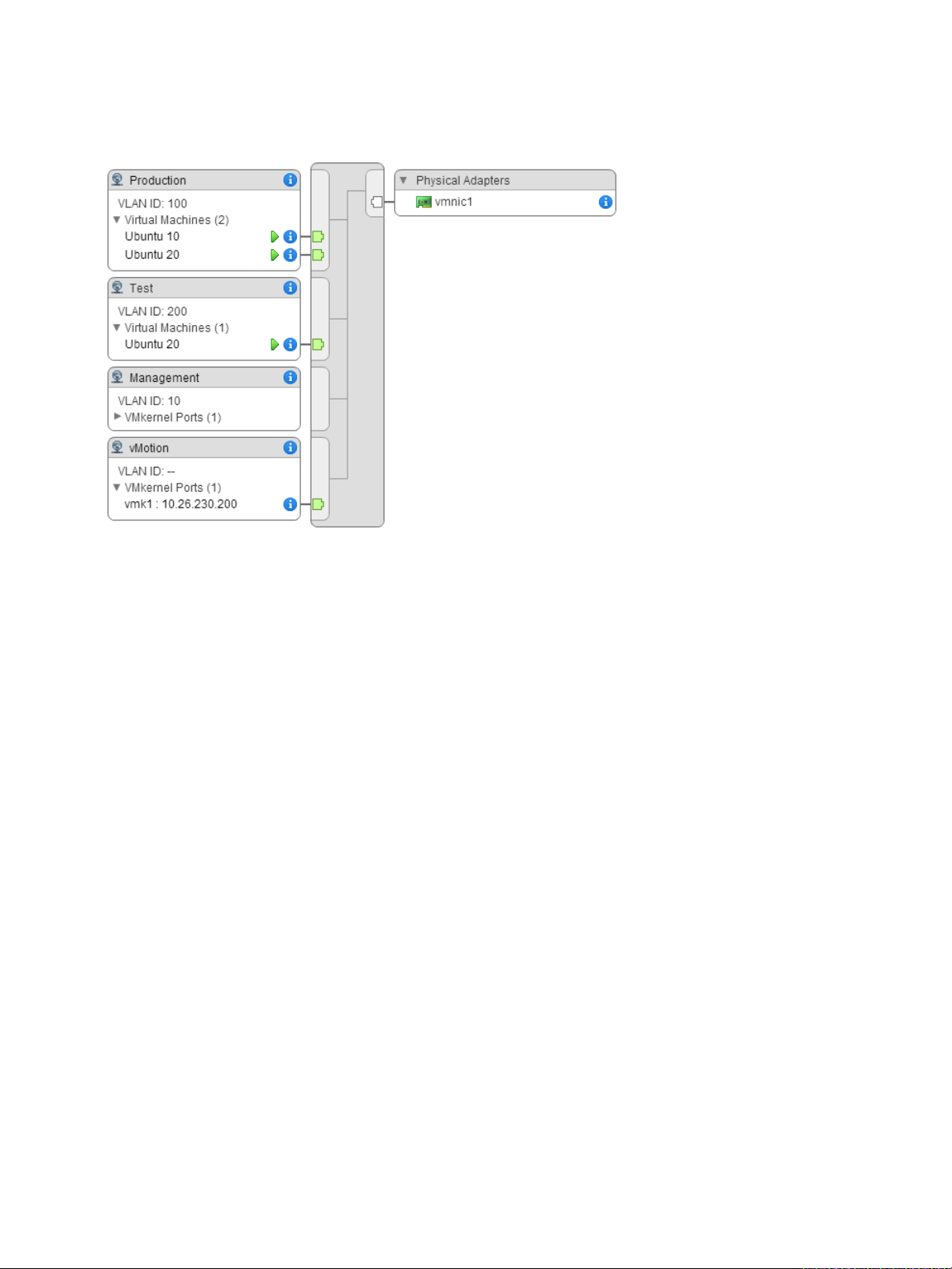
Example: Diagram of a Standard Switch That Connects the VMkernel and
Virtual Machines to the Network
In your virtual environment, a vSphere Standard Switch handles VMkernel adapters for vSphere vMotion
and for the management network, and virtual machines grouped. You can use the central topology
diagram to examine whether a virtual machine or VMkernel adapter is connected to the external network
and to identify the physical adapter that carries the data.
VMware, Inc. 24
Page 25
vSphere Networking
Figure 2‑2. Topology Diagram of a Standard Switch That Connects the VMkernel and Virtual
Machines to the Network
VMware, Inc. 25
Page 26

Setting Up Networking with
vSphere Distributed Switches 3
With vSphere distributed switches you can set up and configure networking in a vSphere environment.
This chapter includes the following topics:
n
vSphere Distributed Switch Architecture
n
Create a vSphere Distributed Switch
n
Upgrade a vSphere Distributed Switch to a Later Version
n
Edit General and Advanced vSphere Distributed Switch Settings
n
Managing Networking on Multiple Hosts on a vSphere Distributed Switch
n
Managing Networking on Host Proxy Switches
n
Distributed Port Groups
n
Working with Distributed Ports
n
Configuring Virtual Machine Networking on a vSphere Distributed Switch
n
Topology Diagrams of a vSphere Distributed Switch in the vSphere Web Client
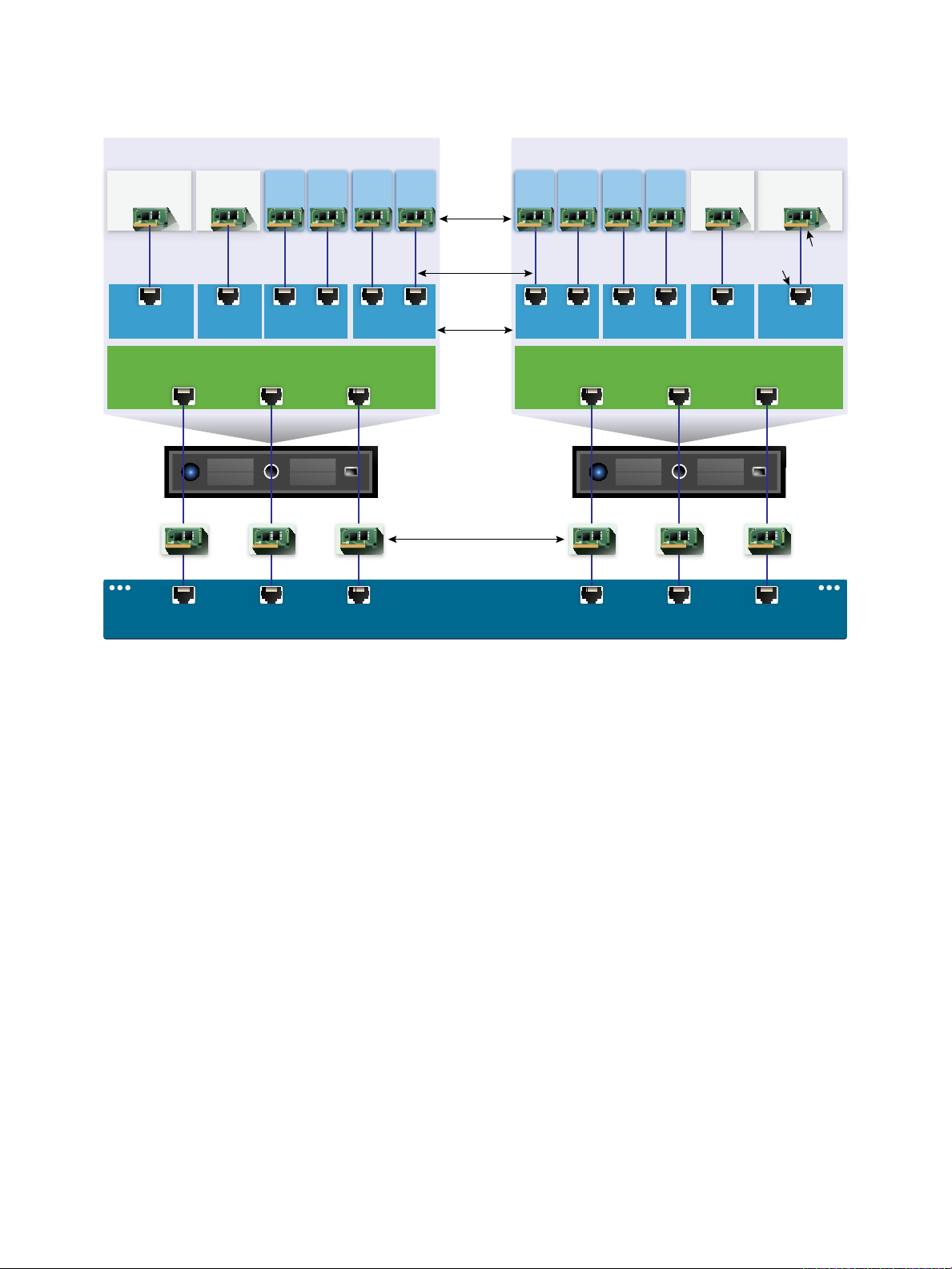
vSphere Distributed Switch Architecture
A vSphere Distributed Switch provides centralized management and monitoring of the networking
configuration of all hosts that are associated with the switch. You set up a distributed switch on a
vCenter Server system, and its settings are propagated to all hosts that are associated with the switch.
VMware, Inc.
26
Page 27
Uplink port group Uplink port group
Uplink2 Uplink3Uplink1
Host 1
Host 2
Uplink port group
vSphere Distributed Switch
vCenter Server
Distributed
port groups
Production network
VMkernel network
vmnic0 vmnic1 vmnic2 vmnic0 vmnic1 vmnic2
Host Proxy Switch
Production
network
VMkernel
network
Production
network
VMkernel
network
Management plane
Data plane
Virtual network
Physical network
Physical NICs
Host Proxy Switch
Physical Switch
vSphere Networking
Figure 3‑1. vSphere Distributed Switch Architecture
A network switch in vSphere consists of two logical sections that are the data plane and the management
plane. The data plane implements the package switching, filtering, tagging, and so on. The management
plane is the control structure that you use to configure the data plane functionality. A vSphere Standard
Switch contains both data and management planes, and you configure and maintain each standard
switch individually.
A vSphere Distributed Switch separates the data plane and the management plane. The management
functionality of the distributed switch resides on the vCenter Server system that lets you administer the
networking configuration of your environment on a data center level. The data plane remains locally on
every host that is associated with the distributed switch. The data plane section of the distributed switch is
called a host proxy switch. The networking configuration that you create on vCenter Server (the
management plane) is automatically pushed down to all host proxy switches (the data plane).
VMware, Inc. 27
Page 28

vSphere Networking
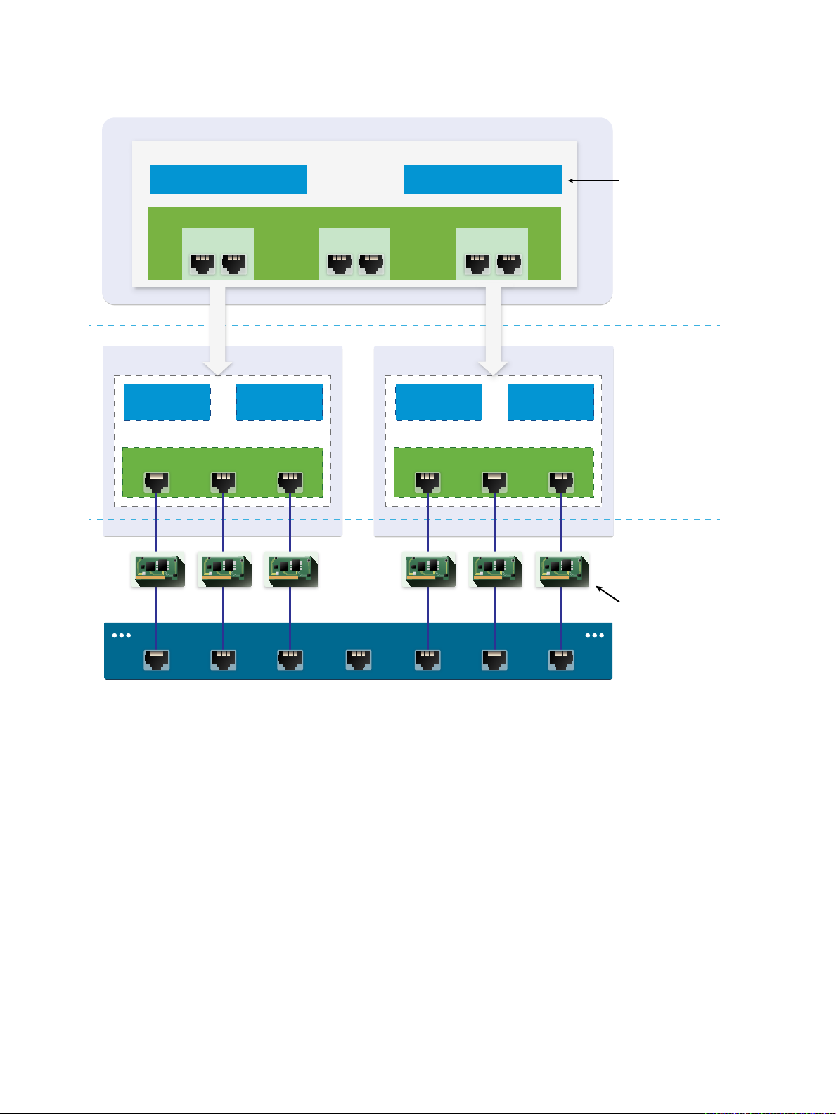
The vSphere Distributed Switch introduces two abstractions that you use to create consistent networking
configuration for physical NICs, virtual machines, and VMkernel services.
Uplink port group An uplink port group or dvuplink port group is defined during the creation of
the distributed switch and can have one or more uplinks. An uplink is a
template that you use to configure physical connections of hosts as well as
failover and load balancing policies. You map physical NICs of hosts to
uplinks on the distributed switch. At the host level, each physical NIC is
connected to an uplink port with a particular ID. You set failover and load
balancing policies over uplinks and the policies are automatically
propagated to the host proxy switches, or the data plane. In this way you
can apply consistent failover and load balancing configuration for the
physical NICs of all hosts that are associated with the distributed switch.
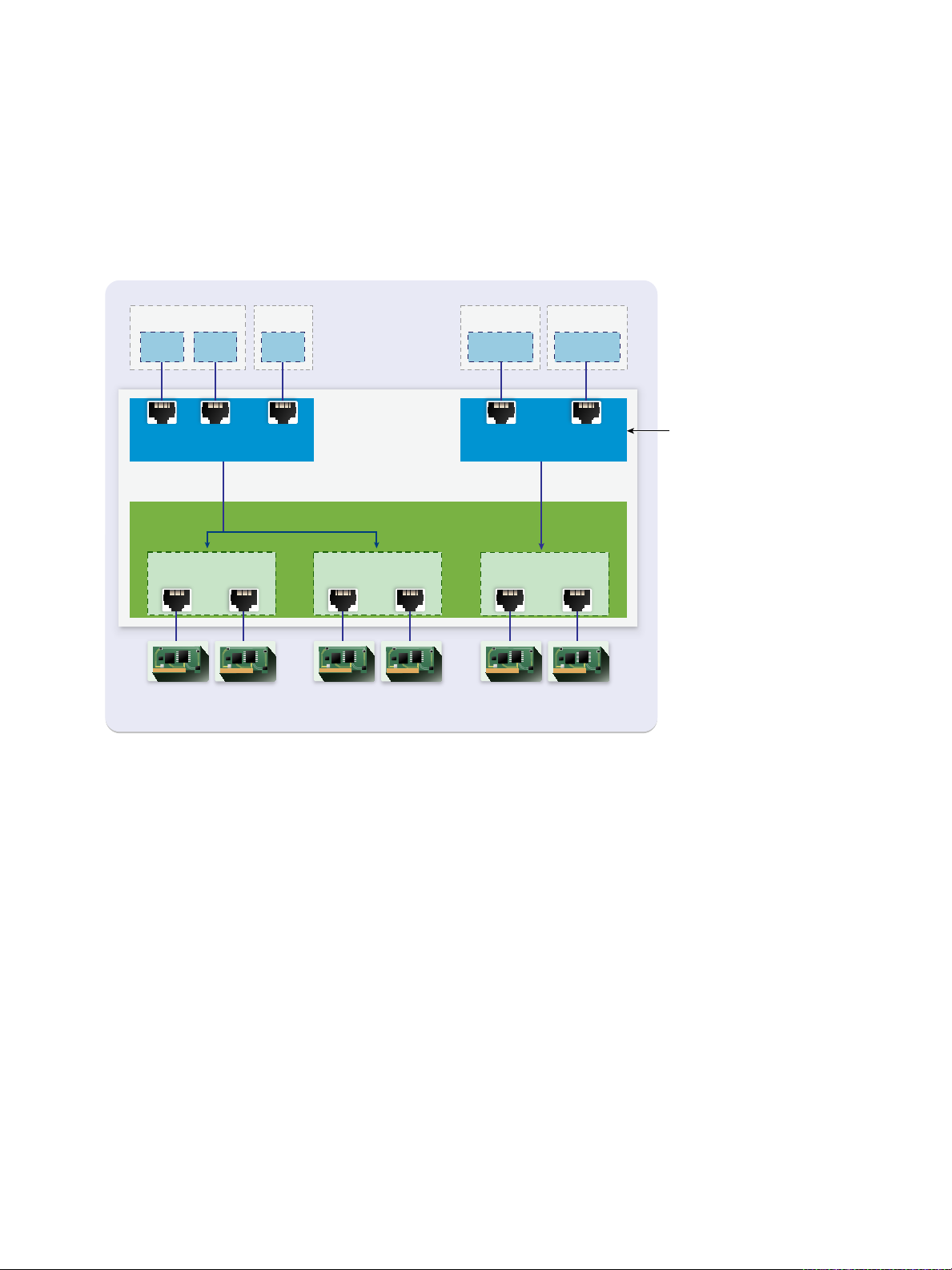
Distributed port group Distributed port groups provide network connectivity to virtual machines
and accommodate VMkernel traffic. You identify each distributed port group
by using a network label, which must be unique to the current data center.
You configure NIC teaming, failover, load balancing, VLAN, security, traffic
shaping , and other policies on distributed port groups. The virtual ports that
are connected to a distributed port group share the same properties that
are configured to the distributed port group. As with uplink port groups, the
configuration that you set on distributed port groups on vCenter Server (the
management plane) is automatically propagated to all hosts on the
distributed switch through their host proxy switches (the data plane). In this
way you can configure a group of virtual machines to share the same
networking configuration by associating the virtual machines to the same
distributed port group.
For example, suppose that you create a vSphere Distributed Switch on your data center and associate
two hosts with it. You configure three uplinks to the uplink port group and connect a physical NIC from
each host to an uplink. In this way, each uplink has two physical NICs from each host mapped to it, for
example Uplink 1 is configured with vmnic0 from Host 1 and Host 2. Next you create the Production and
the VMkernel network distributed port groups for virtual machine networking and VMkernel services.
Respectively, a representation of the Production and the VMkernel network port groups is also created on
Host 1 and Host 2. All policies that you set to the Production and the VMkernel network port groups are
propagated to their representations on Host 1 and Host 2.
To ensure efficient use of host resources, the number of distributed ports of proxy switches is dynamically
scaled up and down on hosts running ESXi 5.5 and later. A proxy switch on such a host can expand up to
the maximum number of ports supported on the host. The port limit is determined based on the maximum
number of virtual machines that the host can handle.
VMware, Inc. 28
Page 29
VMkernel network
vCenter Server
Uplink port group
vSphere Distributed Switch
Host 1
Distributed
port groups
3 4
Host 1 Host 2
vmknic2
Host 2
VM network
0 1 2
vmknic1
Uplink 2
6
vmnic1
(Host1)
9
vmnic1
(Host2)
Uplink 3
7
vmnic2
(Host1)
10
vmnic2
(Host2)
VM1 VM2 VM3
5
vmnic0
(Host1)
8
vmnic0
(Host2)
Uplink 1
vSphere Networking
vSphere Distributed Switch Data Flow
The data flow from the virtual machines and VMkernel adapters down to the physical network depends on
the NIC teaming and load balancing policies that are set to the distributed port groups. The data flow also
depends on the port allocation on the distributed switch.
Figure 3‑2. NIC Teaming and Port Allocation on a vSphere Distributed Switch
For example, suppose that you create the VM network and the VMkernel network distributed port groups,
respectively with 3 and 2 distributed ports. The distributed switch allocates ports with IDs from 0 to 4 in
the order that you create the distributed port groups. Next, you associate Host 1 and Host 2 with the
distributed switch. The distributed switch allocates ports for every physical NIC on the hosts, as the
numbering of the ports continues from 5 in the order that you add the hosts. To provide network
connectivity on each host, you map vmnic0 to Uplink 1, vmnic1 to Uplink 2, and vmnic2 to Uplink 3.
To provide connectivity to virtual machines and to accommodate VMkernel traffic, you configure teaming
and failover to the VM network and to the VMkernel network port groups. Uplink 1 and Uplink 2 handle
the traffic for the VM network port group, and Uplink 3 handles the traffic for the VMkernel network port
group.
VMware, Inc. 29
Page 30
VMkernel
network
Uplink port group
VM network
Host 1
0 1 3
vmnic0 vmnic1
5 6 7
Host Proxy
Switch
vmnic2
VM2 vmknic1VM1
Physical Switch
vSphere Networking
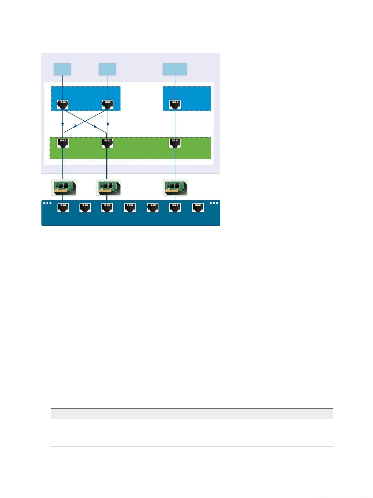
Figure 3‑3. Packet Flow on the Host Proxy Switch
On the host side, the packet flow from virtual machines and VMkernel services passes through particular
ports to reach the physical network. For example, a packet sent from VM1 on Host 1 first reaches port 0
on the VM network distributed port group. Because Uplink 1 and Uplink 2 handle the traffic for the VM
network port group, the packet can continue from uplink port 5 or uplink port 6 . If the packet goes through
uplink port 5, it continues to vmnic0, and if the packet goes to uplink port 6, it continues to vmnic1.
Create a vSphere Distributed Switch
Create a vSphere distributed switch on a data center to handle the networking configuration of multiple
hosts at a time from a central place.
Procedure
1 In the vSphere Web Client, navigate to a data center.
2 In the navigator, right-click the data center and select Distributed Switch > New Distributed Switch.
3 On the Name and location page, type a name for the new distributed switch, or accept the generated
4 On the Select version page, select a distributed switch version and click Next.
name, and click Next.
Option Description
Distributed Switch: 6.5.0 Compatible with ESXi 6.5 and later.
Distributed Switch: 6.0.0 Compatible with ESXi 6.0 and later. Features released with later vSphere
distributed switch versions are not supported.
VMware, Inc. 30
Page 31

vSphere Networking
Option Description
Distributed Switch: 5.5.0 Compatible with ESXi 5.5 and later. Features released with later vSphere
distributed switch versions are not supported.
Distributed Switch: 5.1.0 Compatible with VMware ESXi 5.1 and later. Features released with later vSphere
distributed switch versions are not supported.
Distributed Switch: 5.0.0 Compatible with VMware ESXi 5.0 and later.
Features released with later vSphere distributed switch versions are not
supported.
5 On the Edit settings page, configure the distributed switch settings.
a Use the arrow buttons to select the Number of uplinks.
Uplink ports connect the distributed switch to physical NICs on associated hosts. The number of
uplink ports is the maximum number of allowed physical connections to the distributed switch per
host.
b Use the drop-down menu to enable or disable Network I/O Control.
By using Network I/O Control you can prioritize the access to network resources for certain types
of infrastructure and workload traffic according to the requirements of your deployment. Network
I/O Control continuously monitors the I/O load over the network and dynamically allocates
available resources.
c Select the Create a default port group check box to create a new distributed port group with
default settings for this switch.
d (Optional) To create a default distributed port group, type the port group name in the Port group
name, or accept the generated name.
If your system has custom port group requirements, create distributed port groups that meet
those requirements after you add the distributed switch.
e Click Next.
6 On the Ready to complete page, review the settings you selected and click Finish.
Use the Back button to edit any settings.
A distributed switch is created on the data center. You can view the features supported on the distributed
switch as well as other details by navigating to the new distributed switch and clicking the Summary tab.
What to do next
Add hosts to the distributed switch and configure their network adapters on the switch.
Upgrade a vSphere Distributed Switch to a Later Version
You can upgrade vSphere Distributed Switch version 5.x to a later version. The upgrade lets the
distributed switch take advantage of features that are available only in the later version.
VMware, Inc. 31
Page 32

vSphere Networking
The upgrade of a distributed switch is a nondisruptive operation, that is, the hosts and virtual machines
attached to the switch do not experience any downtime.
Note To be able to restore the connectivity of the virtual machines and VMkernel adapters if the upgrade
fails, back up the configuration of the distributed switch.
If the upgrade is not successful, to recreate the switch with its port groups and connected hosts, you can
import the switch configuration file. See Export vSphere Distributed Switch Configurations and Import a
vSphere Distributed Switch Configuration.
Prerequisites
n
Upgrade vCenter Server to version 6.5.
n
Upgrade all hosts connected to the distributed switch to ESXi 6.5.
Procedure
1 In the vSphere Web Client, navigate to the distributed switch.
2 Right-click the distributed switch and select Upgrade > Upgrade Distributed Switch.
3 Select the vSphere Distributed Switch version that you want to upgrade the switch to and click Next.
Option Description
Version 6.5.0 Compatible with ESXi version 6.5 and later.
Version 6.0.0 Compatible with ESXi version 6.0 and later. Features released with later vSphere
Distributed Switch versions are not supported.
Version 5.5.0 Compatible with ESXi version 5.5 and later. Features released with later vSphere
Distributed Switch versions are not supported.
Version 5.1.0 Compatible with ESXi version 5.1 and later. Features released with later vSphere
Distributed Switch versions are not supported.
4 Review host compatibility and click Next.
Some ESXi instances that are connected to the distributed switch might be incompatible with the
selected target version. Upgrade or remove the incompatible hosts, or select another upgrade version
for the distributed switch.
5 Complete the upgrade configuration and click Finish.
Caution After you upgrade the vSphere Distributed Switch, you cannot revert it to an earlier version.
You also cannot add ESXi hosts that are running an earlier version than the new version of the
switch.
a Review the upgrade settings.
b If you upgrade from vSphere Distributed Switch 5.1, schedule conversion to the enhanced LACP
support.
c If you upgrade from vSphere Distributed Switch 5.1 and later, schedule conversion to Network I/O
Control version 3.
VMware, Inc. 32
Page 33

vSphere Networking
For information about converting to enhanced LACP support, see Convert to the Enhanced LACP
Support on a vSphere Distributed Switch.
For information about converting to Network I/O Control version 3, see Upgrade Network I/O Control to
Version 3 on a vSphere Distributed Switch.
Edit General and Advanced vSphere Distributed Switch Settings
General settings for a vSphere Distributed Switch include the switch name and number of uplinks.
Advanced settings for a distributed switch include Cisco Discovery Protocol and the maximum MTU for
the switch.
Procedure
1 In the vSphere Web Client, navigate to the distributed switch.
2 On the Configure tab, expand Settings and select Properties.
3 Click Edit.
4 Click General to edit the vSphere Distributed Switch settings.
Option Description
Name Type the name for the distributed switch.
Number of uplinks Select the number of uplink ports for the distributed switch.
Click Edit uplink names to change the names of the uplinks.
Number of ports The number of ports for this distributed switch. This cannot be edited.
Network I/O Control Use the drop-down menu to enable or disable Network I/O control.
Description Add or modify a description of the distributed switch settings.
5 Click Advanced to edit the vSphere Distributed Switch settings.
Option Description
MTU (Bytes) Maximum MTU size for the vSphere Distributed Switch. To enable jumbo frames,
set a value greater than 1500 bytes.
Multicast filtering mode
n
Basic. The distributed switch forwards traffic that is related to a multicast
group based on a MAC address generated from the last 23 bits of the IPv4
address of the group.
n
IGMP/MLD snooping. The distributed switch forwards multicast traffic to
virtual machines according to the IPv4 and IPv6 addresses of subscribed
multicast groups by using membership messages defined by the Internet
Group Management Protocol (IGMP ) and Multicast Listener Discovery
protocol.
VMware, Inc. 33
Page 34

vSphere Networking
Option Description
Discovery Protocol a Select Cisco Discovery Protocol, Link Layer Discovery Protocol, or (disabled)
from the Type drop-down menu.
b Set Operation to Listen, Advertise, or Both.
For information about Discovery Protocol, see Switch Discovery Protocol.
Administrator Contact Type the name and other details of the administrator for the distributed switch.
6 Click OK.
Managing Networking on Multiple Hosts on a vSphere Distributed Switch
You create and manage virtual networks on a vSphere Distributed Switch by adding hosts to the switch
and connecting their network adapters to the switch. To create uniform networking configuration
throughout multiple hosts on the distributed switch, you can use a host as a template and apply its
configuration to other hosts.
n
Tasks for Managing Host Networking on a vSphere Distributed Switch
You can add new hosts to a vSphere Distributed Switch, connect network adapters to the switch,
and remove hosts from the switch. In a production environment, you might need to keep the network
connectivity up for virtual machines and VMkernel services while you manage host networking on
the distributed switch.
n
Add Hosts to a vSphere Distributed Switch
To manage the networking of your vSphere environment by using a vSphere Distributed Switch, you
must associate hosts with the switch. You connect the physical NICs, VMkernel adapters, and virtual
machine network adapters of the hosts to the distributed switch.
n
Configure Physical Network Adapters on a vSphere Distributed Switch
For hosts that are associated with a distributed switch, you can assign physical NICs to uplinks on
the switch. You can configure physical NICs on the distributed switch for multiple hosts at a time.
n
Migrate VMkernel Adapters to a vSphere Distributed Switch
Migrate VMkernel adapters to a distributed switch if you want to handle the traffic for VMkernel
services by using only this switch and you no longer need the adapters on other standard or
distributed switches.
n
Create a VMkernel Adapter on a vSphere Distributed Switch
Create a VMkernel adapter on hosts associated with a distributed switch to provide network
connectivity to the hosts and to handle the traffic for vSphere vMotion, IP storage, Fault Tolerance
logging, and vSAN. You can create VMkernel adapters on multiple hosts simultaneously by using the
Add and Manage Hosts wizard.
n
Migrate Virtual Machine Networking to the vSphere Distributed Switch
To manage virtual machine networking by using a distributed switch, migrate virtual machine
network adapters to labeled networks on the switch.
VMware, Inc. 34
Page 35

vSphere Networking
n
Use a Host as a Template to Create a Uniform Networking Configuration on a vSphere Distributed
Switch
If you plan to have hosts with a uniform networking configuration, you can select a host as a
template and apply its configuration for physical NICs and VMkernel adapters to other hosts on the
distributed switch.
n
Remove Hosts from a vSphere Distributed Switch
Remove hosts from a vSphere distributed switch if you have configured a different switch for the
hosts.
Tasks for Managing Host Networking on a vSphere Distributed Switch
You can add new hosts to a vSphere Distributed Switch, connect network adapters to the switch, and
remove hosts from the switch. In a production environment, you might need to keep the network
connectivity up for virtual machines and VMkernel services while you manage host networking on the
distributed switch.
Adding Hosts to a vSphere Distributed Switch
Consider preparing your environment before you add new hosts to a distributed switch.
n
Create distributed port groups for virtual machine networking.
n
Create distributed port groups for VMkernel services. For example, create distributed port groups for
management network, vMotion, and Fault Tolerance.
n
Configure enough uplinks on the distributed switch for all physical NICs that you want to connect to
the switch. For example, if the hosts that you want to connect to the distributed switch have eight
physical NICs each, configure eight uplinks on the distributed switch.
n
Make sure that the configuration of the distributed switch is prepared for services with specific
networking requirements. For example, iSCSI has specific requirements for the teaming and failover
configuration of the distributed port group where you connect the iSCSI VMkernel adapter.
You can use the Add and Manage Hosts wizard in the vSphere Web Client to add multiple hosts at a
time.
Managing Network Adapters on a vSphere Distributed Switch
After you add hosts to a distributed switch, you can connect physical NICs to uplinks on the switch,
configure virtual machine network adapters, and manage VMkernel networking.
If some hosts on a distributed switch are associated to other switches in your data center, you can
migrate network adapters to or from the distributed switch.
If you migrate virtual machine network adapters or VMkernel adapters, make sure that the destination
distributed port groups have at least one active uplink, and the uplink is connected to a physical NIC on
the hosts. Another approach is to migrate physical NICs, virtual network adapters, and VMkernel adapters
simultaneously.
VMware, Inc. 35
Page 36

vSphere Networking
If you migrate physical NICs, leave at least one active NIC that handles the traffic of port groups. For
example, if vmnic0 and vmnic1 handle the traffic of the VM Network port group, migrate vmnic0 and leave
vmnic1 connected to the group.
Removing Hosts from a vSphere Distributed Switch
Before you remove hosts from a distributed switch, you must migrate the network adapters that are in use
to a different switch.
n
To add hosts to a different distributed switch, you can use the Add and Manage Hosts wizard to
migrate the network adapters on the hosts to the new switch all together. You can then remove the
hosts safely from their current distributed switch.
n
To migrate host networking to standard switches, you must migrate the network adapters in stages.
For example, remove physical NICs on the hosts from the distributed switch by leaving one physical
NIC on every host connected to the switch to keep the network connectivity up. Next, attach the
physical NICs to the standard switches and migrate VMkernel adapters and virtual machine network
adapters to the switches. Lastly, migrate the physical NIC that you left connected to the distributed
switch to the standard switches.
Add Hosts to a vSphere Distributed Switch
To manage the networking of your vSphere environment by using a vSphere Distributed Switch, you must
associate hosts with the switch. You connect the physical NICs, VMkernel adapters, and virtual machine
network adapters of the hosts to the distributed switch.
Prerequisites
n
Verify that enough uplinks are available on the distributed switch to assign to the physical NICs that
you want to connect to the switch.
n
Verify that there is at least one distributed port group on the distributed switch.
n
Verify that the distributed port group have active uplinks configured in its teaming and failover policy.
If you migrate or create VMkernel adapters for iSCSI, verify that the teaming and failover policy of the
target distributed port group meets the requirements for iSCSI:
n
Verify that only one uplink is active, the standby list is empty, and the rest of the uplinks are unused.
n
Verify that only one physical NIC per host is assigned to the active uplink.
Procedure
1 In the vSphere Web Client, navigate to the distributed switch.
2 From the Actions menu, select Add and Manage Hosts.
3 On the Select task page, select Add hosts, and click Next.
4 On the Select hosts page, click New hosts, select from the hosts in your data center, click OK, and
then click Next.
VMware, Inc. 36
Page 37

vSphere Networking
5 On the Select network adapter tasks page, select the tasks for configuring network adapters to the
distributed switch and click Next.
6 On the Manage physical network adapters page, configure physical NICs on the distributed switch.
a From the On other switches/unclaimed list, select a physical NIC.
If you select physical NICs that are already connected to other switches, they are migrated to the
current distributed switch.
b Click Assign uplink.
c Select an uplink and click OK.
For consistent network configuration, you can connect one and the same physical NIC on every host
to the same uplink on the distributed switch.
For example, if you are adding two hosts connect vmnic1 on of each host to Uplink1 on the
distributed switch.
7 Click Next.
8 On the Manage VMkernel network adapters page, configure VMkernel adapters.
a Select a VMkernel adapter and click Assign port group.
b Select a distributed port group and click OK.
9 Review the impacted services as well as the level of impact.
Option Description
No impact iSCSI will continue its normal function after the new networking configuration is
applied.
Important impact The normal function of iSCSI might be disrupted if the new networking
configuration is applied.
Critical impact The normal function of iSCSI will be interrupted if the new networking
configuration is applied.
a If the impact on iSCSI is important or critical, click iSCSI entry and review the reasons that are
displayed in the Analysis details pane.
b After you troubleshoot the impact on iSCSI, proceed with your networking configuration.
10 Click Next.
11 On the Migrate VM networking page, configure virtual machine networking.
a To connect all network adapters of a virtual machine to a distributed port group, select the virtual
machine, or select an individual network adapter to connect only that adapter.
b Click Assign port group.
c Select a distributed port group from the list and click OK.
12 Click Next and click Finish.
VMware, Inc. 37
Page 38

vSphere Networking
What to do next
Having hosts associated with the distributed switch, you can manage physical NICs, VMkernel adapters,
and virtual machine network adapters.
Configure Physical Network Adapters on a vSphere Distributed
Switch
For hosts that are associated with a distributed switch, you can assign physical NICs to uplinks on the
switch. You can configure physical NICs on the distributed switch for multiple hosts at a time.
For consistent networking configuration throughout all hosts, you can assign the same physical NIC on
every host to the same uplink on the distributed switch. For example, you can assign vmnic1 from hosts
ESXi A and ESXi B to Uplink 1.
Procedure
1 In the vSphere Web Client, navigate to the distributed switch.
2 From the Actions menu, select Add and Manage Hosts.
3 In Select task, select Manage host networking and click Next.
4 In Select hosts, click Attached hosts and select from the hosts that are associated with the
distributed switch.
5 Click Next.
6 In Select network adapter tasks, select Manage physical adapters and click Next.
7 In Manage physical network adapters, select a physical NIC from the On other switches/unclaimed
list.
If you select physical NICs that are already assigned to other switches, they are migrated to the
current distributed switch.
8 Click Assign uplink.
9 Select an uplink or select Auto-assign.
10 Click Next.
VMware, Inc. 38
Page 39

vSphere Networking
11 Review the impacted services as well as the level of impact.
Option Description
No impact iSCSI will continue its normal function after the new networking configuration is
applied.
Important impact The normal function of iSCSI might be disrupted if the new networking
configuration is applied.
Critical impact The normal function of iSCSI will be interrupted if the new networking
configuration is applied.
a If the impact on iSCSI is important or critical, click iSCSI entry and review the reasons that are
displayed in the Analysis details pane.
b After you troubleshoot the impact on iSCSI, proceed with your networking configuration.
12 Click Next and click Finish.
Migrate VMkernel Adapters to a vSphere Distributed Switch
Migrate VMkernel adapters to a distributed switch if you want to handle the traffic for VMkernel services
by using only this switch and you no longer need the adapters on other standard or distributed switches.
Procedure
1 In the vSphere Web Client, navigate to the distributed switch.
2 From the Actions menu, select Add and Manage Hosts.
3 In Select task, select Manage host networking and click Next.
4 In Select hosts, click Attached hosts and select from the hosts that are associated with the
distributed switch.
5 Click Next.
6 In Select network adapter tasks, select Manage VMkernel adapters and click Next.
7 In Manage VMkernel network adapters, select the adapter and click Assign port group.
8 Select a distributed port group and click OK.
9 Click Next.
VMware, Inc. 39
Page 40

vSphere Networking
10 Review the impacted services as well as the level of impact.
Option Description
No impact iSCSI will continue its normal function after the new networking configuration is
applied.
Important impact The normal function of iSCSI might be disrupted if the new networking
configuration is applied.
Critical impact The normal function of iSCSI will be interrupted if the new networking
configuration is applied.
a If the impact on iSCSI is important or critical, click iSCSI entry and review the reasons that are
displayed in the Analysis details pane.
b After you troubleshoot the impact on iSCSI, proceed with your networking configuration.
11 Click Next and click Finish.
Create a VMkernel Adapter on a vSphere Distributed Switch
Create a VMkernel adapter on hosts associated with a distributed switch to provide network connectivity
to the hosts and to handle the traffic for vSphere vMotion, IP storage, Fault Tolerance logging, and vSAN.
You can create VMkernel adapters on multiple hosts simultaneously by using the Add and Manage
Hosts wizard.
You should dedicate one distributed port group for each VMkernel adapter. One VMkernel adapter should
handle only one traffic type.
Procedure
1 In the vSphere Web Client, navigate to the distributed switch.
2 From the Actions menu, select Add and Manage Hosts.
3 In Select task, select Manage host networking and click Next.
4 In Select hosts, click Attached hosts and select from the hosts that are associated with the
distributed switch.
5 Click Next.
6 In Select network adapter tasks, select Manage VMkernel adapters and click Next.
7 Click New adapter.
The Add Networking wizard opens.
8 In Select target device, select a distributed port group, and click Next.
VMware, Inc. 40
Page 41

vSphere Networking
9 On the Port properties page, configure the settings for the VMkernel adapter.
Option Description
Network label The network label is inherited from the label of the distributed port group.
IP settings Select IPv4, IPv6, or both.
Note The IPv6 option does not appear on hosts that do not have IPv6 enabled.
TCP/IP stack Select a TCP/IP stack from the list. Once you set a TCP/IP stack for the VMkernel
adapter, you cannot change it later. If you select the vMotion or the Provisioning
TCP/IP stack, you will be able to use only these stacks to handle vMotion or
Provisioning traffic on the host. All VMkernel adapters for vMotion on the default
TCP/IP stack are disabled for future vMotion sessions. If you set the Provisioning
TCP/IP stack, VMkernel adapters on the default TCP/IP stack are disabled for
operations that include Provisioning traffic, such as virtual machine cold
migration, cloning, and snapshot migration.
Enable services You can enable services for the default TCP/IP stack on the host. Select from the
available services:
n
vMotion traffic. Enables the VMkernel adapter to advertise itself to another
host as the network connection where vMotion traffic is sent. The migration
with vMotion to the selected host is not possible if the vMotion service is not
enabled for any VMkernel adapter on the default TCP/IP stack, or there are
no adapters using the vMotion TCP/IP stack.
n
Provisioning traffic. Handles the data transferred for virtual machine cold
migration, cloning, and snapshot migration.
n
Fault Tolerance traffic. Enables Fault Tolerance logging on the host. You
can use only one VMkernel adapter for FT traffic per host.
n
Management traffic. Enables the management traffic for the host and
vCenter Server. Typically, hosts have such a VMkernel adapter created when
the ESXi software is installed. You can create another VMkernel adapter for
management traffic on the host to provide redundancy.
n
vSphere Replication traffic. Handles the outgoing replication data that is
sent from the source ESXi host to the vSphere Replication server.
n
vSphere Replication NFC traffic. Handles the incoming replication data on
the target replication site.
n
vSAN. Enables thevSAN traffic on the host. Every host that is part of a vSAN
cluster must have such a VMkernel adapter.
10 If you selected the vMotion TCP/IP or the Provisioning stack, click OK in the warning dialog that
appears.
If a live migration is already initiated, it completes successfully even after the involved VMkernel
adapters on the default TCP/IP stack are disabled for vMotion. Same refers to operations that include
VMkernel adapters on the default TCP/IP stack that are set for the Provisioning traffic.
VMware, Inc. 41
Page 42

vSphere Networking
11 (Optional) On the IPv4 settings page, select an option for obtaining IP addresses.
Option Description
Obtain IPv4 settings automatically Use DHCP to obtain IP settings. A DHCP server must be present on the network.
Use static IPv4 settings Enter the IPv4 IP address and subnet mask for the VMkernel adapter.
The VMkernel Default Gateway and DNS server addresses for IPv4 are obtained
from the selected TCP/IP stack.
Select the Override default gateway for this adapter check box and enter a
gateway address, if you want to specify a different gateway for the VMkernel
adapter.
12 (Optional) On the IPv6 settings page, select an option for obtaining IPv6 addresses.
Option Description
Obtain IPv6 addresses automatically
through DHCP
Obtain IPv6 addresses automatically
through Router Advertisement
Static IPv6 addresses a Click Add IPv6 address to add a new IPv6 address.
Use DHCP to obtain IPv6 addresses. A DHCPv6 server must be present on the
network.
Use router advertisement to obtain IPv6 addresses.
In ESXi 6.5 and later router advertisement is enabled by default and supports the
M and O flags in accordance with RFC 4861.
b Enter the IPv6 address and subnet prefix length, and click OK.
c To change the VMkernel default gateway, click Override default gateway for
this adapter.
The VMkernel Default Gateway address for IPv6 is obtained from the selected
TCP/IP stack.
13 Review your settings selections on the Ready to complete page and click Finish.
14 Follow the prompts to complete the wizard.
Migrate Virtual Machine Networking to the vSphere Distributed Switch
To manage virtual machine networking by using a distributed switch, migrate virtual machine network
adapters to labeled networks on the switch.
Prerequisites
Verify that at least one distributed port group intended for virtual machine networking exists on the
distributed switch.
Procedure
1 In the vSphere Web Client, navigate to the distributed switch.
2 From the Actions menu, select Add and Manage Hosts.
3 In Select task, select Manage host networking and click Next.
4 In Select hosts, click Attached hosts and select from the hosts that are associated with the
distributed switch.
VMware, Inc. 42
Page 43

vSphere Networking
5 Click Next.
6 In Select network adapter tasks, select Migrate virtual machine networking and click Next.
7 Configure virtual machine network adapters to the distributed switch.
a To connect all network adapters of a virtual machine to a distributed port group, select the virtual
machine, or select an individual network adapter to connect only that adapter.
b Click Assign port group.
c Select a distributed port group from the list and click OK.
8 Click Next and click Finish.
Use a Host as a Template to Create a Uniform Networking
Configuration on a vSphere Distributed Switch
If you plan to have hosts with a uniform networking configuration, you can select a host as a template and
apply its configuration for physical NICs and VMkernel adapters to other hosts on the distributed switch.
Procedure
1 In the vSphere Web Client, navigate to the distributed switch.
2 From the Actions menu, select Add and Manage Hosts.
3 Select a task for managing host networking and click Next.
4 Select the hosts to add or manage on the distributed switch.
5 At the bottom of the dialog box, select Configure identical networking settings on multiple hosts
and click Next.
6 Select a host to use as a template and click Next.
7 Select the network adapter tasks and click Next.
8 On the Manage physical network adapters and Manage VMkernel network adapters pages, make the
configuration changes that you need on the template host, and click Apply to all for all other hosts.
9 On the Ready to complete page, click Finish.
Example: Configure Physical and VMkernel Adapters by Using a Template
Host
Use the template host mode in the Add and Manage Hosts wizard to create a uniform networking
configuration among all the hosts on a distributed switch.
On the Manage physical network adapters page of the wizard, assign a physical NIC to an uplink on the
template host and then click Apply to all to create the same configuration on the other host.
VMware, Inc. 43
Page 44

vSphere Networking
Figure 3‑4. Applying Physical NICs Configuration on a vSphere Distributed Switch by Using
a Template Host
On the Manage VMkernel network adapters page, assign a VMkernel adapter to a port group and click
Apply to all to apply the same configuration to the other host.
After you click the Apply to all button, the destination VMkernel adapter has both the Modified and the
Reassigned qualifiers. The Modified qualifier appears, because when you click the Apply to all button,
vCenter Server copies the configuration specifications of the template VMKernel adapter to the
destination VMkernel adapter even if the configurations of the template and destination adapters are
identical. As a result, the destination adapters are always modified.
VMware, Inc. 44
Page 45

vSphere Networking
Figure 3‑5. Applying VMkernel Adapter Configuration on a vSphere Distributed Switch by
Using a Template Host
Remove Hosts from a vSphere Distributed Switch
Remove hosts from a vSphere distributed switch if you have configured a different switch for the hosts.
Prerequisites
n
Verify that physical NICs on the target hosts are migrated to a different switch.
n
Verify that VMkernel adapters on the hosts are migrated to a different switch.
n
Verify that virtual machine network adapters are migrated to a different switch.
For details about migrating network adapters to different switches, see Tasks for Managing Host
Networking on a vSphere Distributed Switch
Procedure
1 In the vSphere Web Client, navigate to the distributed switch.
2 From the Actions menu, select Add and Manage Hosts.
3 Select Remove hosts and click Next.
4 Select the hosts you want to remove and click Next.
5 Click Finish.
VMware, Inc. 45
Page 46

vSphere Networking
Managing Networking on Host Proxy Switches
You can change the configuration of the proxy switch on every host that is associated with a vSphere
distributed switch. You can manage physical NICs, VMkernel adapters, and virtual machine network
adapters.
For details about setting up VMkernel networking on host proxy switches, see Create a VMkernel Adapter
on a vSphere Distributed Switch.
Migrate Network Adapters on a Host to a vSphere Distributed Switch
For hosts associated with a distributed switch, you can migrate network adapters from a standard switch
to the distributed switch. You can migrate physical NICs, VMkernel adapters, and virtual machine network
adapters at the same time.
To migrate virtual machine network adapters or VMkernel adapters, make sure that the destination
distributed port groups have at least one active uplink, and the uplink is connected to a physical NIC on
this host. Alternatively, migrate physical NICs, virtual network adapters, and VMkernel adapters at once.
To migrate physical NICs, make sure that the source port groups on the standard switch have at least one
physical NIC to handle their traffic. For example, if you migrate a physical NIC that is assigned to a port
group for virtual machine networking, make sure that the port group is connected to at least one physical
NIC. Otherwise the virtual machines on same VLAN on the standard switch will have connectivity
between each other but not to the external network.
Procedure
1 In the vSphere Web Client, navigate to the host.
2 On the Configure tab, expand Networking and select Virtual switches.
3 Select the destination distributed switch and click Migrate physical or virtual network adapters to
this distributed switch.
4 Select the tasks for migrating network adapters and click Next.
5 Configure physical NICs.
a From the On other switches/unclaimed list, select a physical NIC and click Assign uplink.
b Select an uplink and click OK.
c Click Next.
6 Configure VMkernel adapters.
a Select an adapter and click Assign port group.
b Select a distributed port group and click OK.
You should connect one VMkernel adapter to one distributed port group at a time.
c Click Next.
VMware, Inc. 46
Page 47

vSphere Networking
7 Review the services that are affected from the new networking configuration.
a If there is an important or serious impact reported on a service, click the service and review the
analysis details.
For example, an important impact on iSCSI might be reported as a result from an incorrect
teaming and failover configuration on the distributed port group where you migrate the iSCSI
VMkernel adapter. You must leave one active uplink on the teaming and failover order of the
distributed port group, leave the standby list empty, and move the rest of the uplinks to unused.
b After troubleshooting any impact on the affected services, click Next.
8 Configure virtual machine network adapters.
a Select a virtual machine or a virtual machine network adapter and click Assign port group.
If you select a virtual machine, you migrate all network adapters on the virtual machine. If you
select a network adapter, you migrate only this network adapter.
b Select a distributed port group from the list and click OK.
c Click Next.
9 On the Ready to complete page, review the new networking configuration and click Finish.
Migrate a VMkernel Adapter on a Host to a vSphere Standard Switch
If a host is associated with a distributed switch, you can migrate VMkernel adapters from the distributed to
a standard switch.
For details about creating VMkernel adapters on a vSphere distributed switch, see Create a VMkernel
Adapter on a vSphere Distributed Switch.
Prerequisites
Verify that the destination standard switch has at least one physical NIC.
Procedure
1 In the vSphere Web Client, navigate to the host.
2 On the Configure tab, expand Networking and select Virtual switches.
3 Select the destination standard switch from the list.
4 Click Migrate a VMkernel network adapter to the selected switch.
5 On the Select VMkernel network adapter page, select the virtual network adapter to migrate to the
standard switch from the list.
6 On the Configure settings page, edit the Network label and VLAN ID for the network adapter.
7 On the Ready to complete page, review the migration details and click Finish.
Click Back to edit settings.
VMware, Inc. 47
Page 48

vSphere Networking
Assign a Physical NIC of a Host to a vSphere Distributed Switch
You can assign physical NICs of a host that is associated with a distributed switch to uplink port on the
host proxy switch.
Procedure
1 In the vSphere Web Client, navigate to the host.
2 On the Configure tab, expand Networking and select Virtual switches.
3 Select a distributed switch from the list.
4 Click the Manage the physical network adapters connected to the selected switch icon.
5 Select a free uplink from the list and click Add adapter.
6 Select a physical NIC and click OK.
Remove a Physical NIC from a vSphere Distributed Switch
You can remove a physical NIC of a host from an uplink on a vSphere distributed switch.
Procedure
1 In the vSphere Web Client, navigate to the host.
2 On the Configure tab, expand Networking and select Virtual switches.
3 Select the distributed switch.
4 Click the Manage the physical network adapters connected to the selected switch icon.
5 Select an uplink an click Remove selected adapters.
6 Click OK.
What to do next
When you remove physical NICs from active virtual machines, you might see the NICs you removed
reported in the vSphere Web Client. See Removing NICs from Active Virtual Machines.
Removing NICs from Active Virtual Machines
When you remove NICs from active virtual machines, you might still see the NICs you have removed in
the vSphere Web Client.
Removing NICs from an Active Virtual Machine Without a Guest Operating
System Installed
You cannot remove NICs from an active virtual machine on which no operating system is installed.
The vSphere Web Client might report that the NIC has been removed, but you continue to see it attached
to the virtual machine.
VMware, Inc. 48
Page 49

vSphere Networking
Removing NICs from an Active Virtual Machine with a Guest Operating
System Installed
You can remove a NIC from an active virtual machine, but it might not be reported to the
vSphere Web Client for some time. If you click Edit Settings for the virtual machine, you might see the
removed NIC listed even after the task is complete. The Edit Settings dialog box for the virtual machine
does not immediately display the removed NIC.
You might also still see the NIC attached to the virtual machine if the guest operating system of the virtual
machine does not support hot removal of NICs.
Distributed Port Groups
A distributed port group specifies port configuration options for each member port on a vSphere
distributed switch. Distributed port groups define how a connection is made to a network.
Add a Distributed Port Group
Add a distributed port group to a vSphere Distributed Switch to create a distributed switch network for
your virtual machines and to associate VMkernel adapters.
Procedure
1 In the vSphere Web Client, navigate to the distributed switch.
2 Right-click the distributed switch and select Distributed port group > New distributed port group.
3 On the Select name and location page, enter the name of the new distributed port group, or accept
the generated name, and click Next.
4 On the Configure settings page, set the general properties for the new distributed port group and click
Next.
Setting Description
Port binding Select when ports are assigned to virtual machines connected to this distributed
port group.
n
Static binding: Assign a port to a virtual machine when the virtual machine
connects to the distributed port group.
n
Dynamic binding: Assign a port to a virtual machine the first time the virtual
machine powers on after it is connected to the distributed port group.
Dynamic binding has been deprecated since ESXi 5.0.
n
Ephemeral - no binding: No port binding. You can assign a virtual machine
to a distributed port group with ephemeral port binding also when connected
to the host.
Port allocation
Number of ports Enter the number of ports on the distributed port group.
n
Elastic: The default number of ports is eight. When all ports are assigned, a
new set of eight ports is created. This is the default.
n
Fixed: The default number of ports is set to eight. No additional ports are
created when all ports are assigned.
VMware, Inc. 49
Page 50

vSphere Networking
Setting Description
Network resource pool Use the drop-down menu to assign the new distributed port group to a user-
defined network resource pool. If you have not created a network resource pool,
this menu is empty.
VLAN Use the VLAN type drop-down menu to select VLAN options:
n
None: Do not use VLAN.
n
VLAN: In the VLAN ID text box, enter a number between 1 and 4094.
n
VLAN trunking: Enter a VLAN trunk range.
n
Private VLAN: Select a private VLAN entry. If you did not create any private
VLANs, this menu is empty.
Advanced To customize the policy configurations for the new distributed port group, select
this check box.
5 (Optional) On the Security page, edit the security exceptions and click Next.
Setting Description
Promiscuous mode
n
Reject. Placing an adapter in promiscuous mode from the guest operating
system does not result in receiving frames for other virtual machines.
n
Accept. If an adapter is placed in promiscuous mode from the guest
operating system, the switch allows the guest adapter to receive all frames
passed on the switch in compliance with the active VLAN policy for the port
where the adapter is connected.
Firewalls, port scanners, intrusion detection systems, and so on, need to run
in promiscuous mode.
MAC address changes
n
Reject. If you set this option to Reject and the guest OS changes the MAC
address of the adapter to a value different from the address in the .vmx
configuration file, the switch drops all inbound frames to the virtual machine
adapter.
If the guest OS changes the MAC address back, the virtual machine receives
frames again.
n
Accept. If the guest OS changes the MAC address of a network adapter, the
adapter receives frames to its new address.
Forged transmits
n
Reject. The switch drops any outbound frame with a source MAC address
that is different from the one in the .vmx configuration file.
n
Accept. The switch does not perform filtering and permits all outbound
frames.
6 (Optional) On the Traffic shaping page, enable or disable Ingress or Egress traffic shaping and click
Next.
Setting Description
Status If you enable either Ingress traffic shaping or Egress traffic shaping, you are
setting limits on the amount of networking bandwidth allocated for each virtual
adapter associated with this particular port group. If you disable the policy,
services have a free, clear connection to the physical network by default.
Average bandwidth Establishes the number of bits per second to allow across a port, averaged over
time. This is the allowed average load.
VMware, Inc. 50
Page 51

vSphere Networking
Setting Description
Peak bandwidth The maximum number of bits per second to allow across a port when it is sending
and receiving a burst of traffic. This tops the bandwidth used by a port whenever it
is using its burst bonus.
Burst size The maximum number of bytes to allow in a burst. If this parameter is set, a port
might gain a burst bonus when it does not use all its allocated bandwidth.
Whenever the port needs more bandwidth than specified by Average bandwidth,
it might temporarily transmit data at a higher speed if a burst bonus is available.
This parameter tops the number of bytes that might be accumulated in the burst
bonus and thus transferred at a higher speed.
7 (Optional) On the Teaming and failover page, edit the settings and click Next.
Setting Description
Load balancing Specify how to choose an uplink.
n
Route based on originating virtual port. Choose an uplink based on the
virtual port where the traffic entered the distributed switch.
n
Route based on IP hash. Choose an uplink based on a hash of the source
and destination IP addresses of each packet. For non-IP packets, whatever is
at those offsets is used to compute the hash.
n
Route based on source MAC hash. Choose an uplink based on a hash of
the source Ethernet.
n
Route based on physical NIC load. Choose an uplink based on the current
loads of physical NICs.
n
Use explicit failover order. Always use the highest order uplink from the list
of Active adapters which passes failover detection criteria.
Note IP-based teaming requires that the physical switch be configured with
EtherChannel. For all other options, disable EtherChannel.
Network failure detection Specify the method to use for failover detection.
n
Link status only. Relies solely on the link status that the network adapter
provides. This option detects failures, such as cable pulls and physical switch
power failures, but not configuration errors, such as a physical switch port
being blocked by spanning tree or that is misconfigured to the wrong VLAN or
cable pulls on the other side of a physical switch.
n
Beacon probing. Sends out and listens for beacon probes on all NICs in the
team and uses this information, in addition to link status, to determine link
failure. This detects many of the failures previously mentioned that are not
detected by link status alone.
Note Do not use beacon probing with IP-hash load-balancing.
Notify switches Select Yes or No to notify switches in case of failover. If you select Yes, whenever
a virtual NIC is connected to the distributed switch or whenever that virtual NIC’s
traffic might be routed over a different physical NIC in the team because of a
failover event, a notification is sent out over the network to update the lookup
tables on physical switches. In almost all cases, this process is desirable for the
lowest latency of failover occurrences and migrations with vMotion.
Note Do not use this option when the virtual machines using the port group are
using Microsoft Network Load Balancing in unicast mode. No such issue exists
with NLB running in multicast mode.
VMware, Inc. 51
Page 52

vSphere Networking
Setting Description
Failback Select Yes or No to disable or enable failback.
This option determines how a physical adapter is returned to active duty after
recovering from a failure. If failback is set to Yes (default), the adapter is returned
to active duty immediately upon recovery, displacing the standby adapter that
took over its slot, if any. If failback is set to No, a failed adapter is left inactive
even after recovery until another currently active adapter fails, requiring its
replacement.
Failover order Specify how to distribute the workload for uplinks. To use some uplinks but
reserve others for emergencies if the uplinks in use fail, set this condition by
moving them into different groups:
n
Active uplinks. Continue to use the uplink when the network adapter
connectivity is up and active.
n
Standby uplinks . Use this uplink if one of the active adapters' connectivity is
down.
n
Unused uplinks . Do not use this uplink.
Note When using IP-hash load-balancing, do not configure standby uplinks.
8 (Optional) On the Monitoring page, enable or disable NetFlow and click Next.
Setting Description
Disabled NetFlow is disabled on the distributed port group.
Enabled NetFlow is enabled on the distributed port group. NetFlow settings can be
configured at the vSphere Distributed Switch level.
9 (Optional) On the Miscellaneous page, select Yes or No and click Next.
Selecting Yes shuts down all ports in the port group. This action might disrupt the normal network
operations of the hosts or virtual machines using the ports.
10 (Optional) On the Edit additional settings page, add a description of the port group and set any policy
overrides per port and click Next.
11 On the Ready to complete page, review your settings and click Finish.
To change any settings, click the Back button .
Edit General Distributed Port Group Settings
You can edit general distributed port group settings such as the distributed port group name, port settings
and network resource pool.
Procedure
1 Locate a distributed port group in the vSphere Web Client.
a Select a distributed switch and click the Networks tab.
b Click Distributed Port Groups.
2 Right-click the distributed port group and select Edit Settings.
VMware, Inc. 52
Page 53

vSphere Networking
3 Select General to edit the following distributed port group settings.
Option Description
Name The name of distributed port group. You can edit the name in the text field.
Port binding Choose when ports are assigned to virtual machines connected to this distributed
port group.
n
Static binding: Assign a port to a virtual machine when the virtual machine
connects to the distributed port group.
n
Dynamic binding: Assign a port to a virtual machine the first time the virtual
machine powers on after it is connected to the distributed port group.
Dynamic binding has been deprecated since ESXi 5.0.
n
Ephemeral: No port binding. You can also assign a virtual machine to a
distributed port group with ephemeral port binding when connected to the
host.
Port allocation
Number of ports Enter the number of ports on the distributed port group.
Network resource pool Use the drop-down menu to assign the new distributed port group to a user-
Description Enter any information about the distributed port group in the description field.
n
Elastic: The default number of ports is set to eight. When all ports are
assigned, a new set of eight ports is created. This is the default.
n
Fixed: The default number of ports is set to eight. No additional ports are
created when all ports are assigned.
defined network resource pool. If you have not created a network resource pool,
this menu is empty.
4 Click OK.
Configure Overriding Networking Policies on Port Level
To apply different policies for distributed ports, you configure the per-port overriding of the policies that are
set at the port group level. You can also enable the reset of any configuration that is set on per-port level
when a distributed port disconnects from a virtual machine.
Procedure
1 Locate a distributed port group in the vSphere Web Client.
a Select a distributed switch and click the Networks tab.
b Click Distributed Port Groups.
2 Right-click the distributed port group and select Edit Settings.
3 Select the Advanced page.
Option Description
Configure reset at disconnect From the drop-down menu, enable or disable reset at disconnect.
When a distributed port is disconnected from a virtual machine, the configuration
of the distributed port is reset to the distributed port group setting. Any per-port
overrides are discarded.
Override port policies Select the distributed port group policies to be overridden on a per-port level.
VMware, Inc. 53
Page 54

vSphere Networking
4 (Optional) Use the policy pages to set overrides for each port policy.
5 Click OK.
Remove a Distributed Port Group
Remove a distributed port group when you no longer need the corresponding labeled network to provide
connectivity and configure connection settings for virtual machines or VMkernel networking.
Prerequisites
n
Verify that all virtual machines connected to the corresponding labeled network are migrated to a
different labeled network.
n
Verify that all VMkernel adapters connected to the distributed port group are migrated to a different
port group, or are deleted.
Procedure
1 Locate a distributed port group in the vSphere Web Client.
a Select a distributed switch and click the Networks tab.
b Click Distributed Port Groups.
2 Select the distributed port group.
3 From the Actions menu, select Delete.
Working with Distributed Ports
A distributed port is a port on a vSphere distributed switch that connects to the VMkernel or to a virtual
machine's network adapter.
Default distributed port configuration is determined by the distributed port group settings, but some
settings for individual distributed ports can be overridden.
Monitor the State of Distributed Ports
vSphere can monitor distributed ports and provide information about the current state and runtime
statistics of each port.
Procedure
1 Locate a distributed port group in the vSphere Web Client.
a Select a distributed switch and click the Networks tab.
b Click Distributed Port Groups.
2 Double-click a distributed port group.
3 Click the Ports tab and select a port from the list.
VMware, Inc. 54
Page 55

vSphere Networking
4 Click the Start Monitoring Port State icon.
The ports table for the distributed port group displays runtime statistics for each distributed port.
The State column displays the current state for each distributed port.
Option Description
Link Up The link for this distributed port is up.
Link Down The link for this distributed port is down.
Blocked This distributed port is blocked.
-- The state of this distributed port is currently unavailable.
Configure Distributed Port Settings
You can change general distributed port settings such as the port name and description.
Procedure
1 Locate a distributed port group in the vSphere Web Client.
a Select a distributed switch and click the Networks tab.
b Click Distributed Port Groups.
2 Double-click a distributed port group from the list.
3 Click the Ports tab, and select a distributed port from the table.
Information about the distributed port appears at the bottom of the screen.
4 Click the Edit distributed port settings icon.
5 On the Properties page and policy pages, edit information about the distributed port and click OK.
If overrides are not allowed, the policy options are disabled.
You can allow overrides at the port level by changing the Advanced settings of the distributed port
group. See Configure Overriding Networking Policies on Port Level.
Configuring Virtual Machine Networking on a vSphere
Distributed Switch
Connect virtual machines to a vSphere distributed switch either by configuring an individual virtual
machine NIC or migrating groups of virtual machines from the vSphere distributed switch itself.
Connect virtual machines to vSphere distributed switches by connecting their associated virtual network
adapters to distributed port groups. You can do this either for an individual virtual machine by modifying
the virtual machine’s network adapter configuration, or for a group of virtual machines by migrating virtual
machines from an existing virtual network to a vSphere distributed switch.
VMware, Inc. 55
Page 56

vSphere Networking
Migrate Virtual Machines to or from a vSphere Distributed Switch
In addition to connecting virtual machines to a distributed switch at the individual virtual machine level,
you can migrate a group of virtual machines between a vSphere Distributed Switch network and a
vSphere Standard Switch network.
Procedure
1 In the vSphere Web Client, navigate to a data center.
2 Right-click the data center in the navigator and select Migrate VMs to Another Network.
3 Select a source network.
n
Select Specific network and use the Browse button to select a specific source network.
n
Select No network to migrate all virtual machine network adapters that are not connected to any
other network.
4 Use Browse to select a destination network and click Next.
5 Select virtual machines from the list to migrate from the source network to the destination network
and click Next.
6 Review your selections and click Finish.
Click Back to edit any selections.
Connect an Individual Virtual Machine to a Distributed Port Group
Connect an individual virtual machine to a vSphere Distributed Switch by modifying the NIC configuration
of the virtual machine.
Procedure
1 Locate the virtual machine in the vSphere Web Client.
a Select a data center, folder, cluster, resource pool, or host and click the VMs tab.
b Click Virtual Machines and double-click the virtual machine from the list.
2 On the Configure tab of the virtual machine, expand Settings and select VM Hardware.
3 Click Edit.
4 Expand the Network adapter section and select Show more networks from the Network adapter
drop-down menu.
5 In the Select Network dialog box, select a distributed port group and click OK.
6 Click OK.
VMware, Inc. 56
Page 57

vSphere Networking
Topology Diagrams of a vSphere Distributed Switch in the vSphere Web Client
The topology diagrams of a vSphere Distributed Switch in the vSphere Web Client show the structure of
virtual machine adapters, VMkernel adapters, and physical adapters in the switch.
You can examine the components, arranged in port groups, whose traffic is handled by the switch, and
the connections between them. The diagram displays information about the physical adapter that
connects the virtual adapters to the external network.
You can view the components that are running on the entire distributed switch and on each host
participating in it.
Watch the video about the operations that you can perform from the topology diagram of vSphere
Distributed Switch.
Handling Virtual Networking by Using the VDS Topology Diagram
(http://link.brightcove.com/services/player/bcpid2296383276001?
bctid=ref:video_using_vds_topology_diagram)
Central Topology Diagram
You can use the central topology diagram of the switch to locate and edit the settings for distributed port
groups and uplink groups associated with multiple hosts. You can initiate migration of virtual machine
adapters from a port group to a destination on the same or different switch. You can also reorganize the
hosts and their networking on the switch by using the Add and Manage Hosts wizard.
Topology Diagram of a Host Proxy Switch
The topology diagram of a host proxy switch shows the adapters attached to the switch ports on the host.
You can edit the settings of the VMkernel and physical adapters.
Diagram Filters
You can use diagram filters to limit the information displayed in topology diagrams. The default filter limits
the topology diagram to display 32 port groups, 32 hosts, and 1024 virtual machines.
You can change the scope of the diagram by using no filters or by applying custom filters. By using a
custom filter, you can view information only about a set of virtual machines, a set of port groups on certain
hosts, or a port. You can create filters from the central topology diagram of the distributed switch.
View the Topology of a vSphere Distributed Switch
Examine the organization of components that are connected to the distributed switch across the hosts in
a vCenter Server.
Procedure
1 Navigate to the vSphere distributed switch in the vSphere Web Client.
VMware, Inc. 57
Page 58

vSphere Networking
2 On the Configure tab, expand Settings and selectTopology.
By default the diagram shows up to 32 distributed port groups, 32 hosts, and 1024 virtual machines.
Example: Diagram of a Distributed Switch That Connects the VMkernel and
Virtual Machines to the Network
In your virtual environment, a vSphere Distributed Switch handles VMkernel adapters for vSphere
vMotion and for the management network, and virtual machines grouped. You can use the central
topology diagram to examine whether a virtual machine or VMkernel adapter is connected to the external
network and to identify the physical adapter that carries the data.
Figure 3‑6. Topology Diagram of a Distributed Switch That Handles VMkernel and Virtual
Machine Networking
What to do next
You can perform the following common tasks in the topology of the distributed switch:
n
Use filters to view the networking components only for selected port groups on certain hosts, for
selected virtual machines, or for a port.
n
Locate, configure and migrate virtual machine networking components across host and port groups
by using the Migrate Virtual Machine Networking wizard.
n
Detect the virtual machine adapters that have no network assigned and move them to the selected
port group by using the Migrate Virtual Machine Networking wizard.
VMware, Inc. 58
Page 59

vSphere Networking
n
Handle networking components on multiple hosts by using the Add and Manage Hosts wizard.
n
View the physical NIC or NIC team that carries the traffic related to a selected virtual machine adapter
or VMkernel adapter.
In this way you can also view the host on which a selected VMkernel adapter resides. Select the
adapter, trace the route to the associated physical NIC, and view the IP address or domain name next
to the NIC.
n
Determine the VLAN mode and ID for a port group. For information about VLAN modes, see VLAN
Configuration.
View the Topology of a Host Proxy Switch
Examine and reorganize the networking of the VMkernel and virtual machines that the vSphere
Distributed Switch handles on a host.
Procedure
1 In the vSphere Web Client, navigate to the host.
2 On the Configure tab, expand Networking and select Virtual switches.
3 Select the distributed switch from the list.
The topology of the host proxy switch appears under the list.
VMware, Inc. 59
Page 60

Setting Up VMkernel
Networking 4
You set up VMkernel adapters to provide network connectivity to hosts and to accommodate system
traffic of vMotion, IP storage, Fault Tolerance logging, vSAN, and so on.
n
VMkernel Networking Layer
The VMkernel networking layer provides connectivity to hosts and handles the standard system
traffic of vSphere vMotion, IP storage, Fault Tolerance, vSAN, and others. You can also create
VMkernel adapters on the source and target vSphere Replication hosts to isolate the replication data
traffic.
n
View Information About VMkernel Adapters on a Host
You can view each VMkernel adapter's assigned services, associated switch, port settings, IP
settings, TCP/IP stack, VLAN ID, and policies.
n
Create a VMkernel Adapter on a vSphere Standard Switch
Create a VMkernel network adapter on a vSphere standard switch to provide network connectivity
for hosts and to handle the system traffic for vSphere vMotion, IP storage, Fault Tolerance logging,
vSAN, and so on. You can also create VMkernel adapters on the source and target vSphere
Replication hosts to isolate the replication data traffic. Dedicate a VMkernel adapter to only one
traffic type.
n
Create a VMkernel Adapter on a Host Associated with a vSphere Distributed Switch
Create a VMkernel adapter on a host that is associated with a distributed switch to provide network
connectivity to the host and to handle the traffic for vSphere vMotion, IP storage, Fault Tolerance
logging, vSAN, and others. You can set up VMkernel adapters for the standard system traffic on
vSphere standard switches and on vSphere distributed switches.
n
Edit a VMkernel Adapter Configuration
You might have to change the supported traffic type for a VMkernel adapter, or the way IPv4 or IPv6
addresses are obtained.
n
Overriding the Default Gateway of a VMkernel Adapter
You might need to override the default gateway for a VMkernel adapter to provide a different
gateway for services such as vMotion and Fault Tolerance logging.
n
Configure the VMkernel Adapter Gateway by Using ESXCLI
You can override the default gateway of a VMkernel adapter to provide a different gateway for
services such as vMotion, Fault Tolerance logging, and vSAN.
VMware, Inc.
60
Page 61

vSphere Networking
n
View TCP/IP Stack Configuration on a Host
You can view the DNS and routing configuration of a TCP/IP stack on a host. You can also view the
IPv4 and IPv6 routing tables, the congestion control algorithm, and the maximum number of allowed
connections.
n
Change the Configuration of a TCP/IP Stack on a Host
You can change the DNS and default gateway configuration of a TCP/IP stack on a host. You can
also change the congestion control algorithm, the maximum number of connections, and the name
of custom TCP/IP stacks.
n
Create a Custom TCP/IP Stack
You can create a custom TCP/IP stack on a host to forward networking traffic through a custom
application.
n
Remove a VMkernel Adapter
Remove a VMkernel adapter from a vSphere distributed or a standard switch when you no longer
need the adapter. Make sure that you leave at least one VMkernel adapter for management traffic
on the host to keep the network connectivity up.
VMkernel Networking Layer
The VMkernel networking layer provides connectivity to hosts and handles the standard system traffic of
vSphere vMotion, IP storage, Fault Tolerance, vSAN, and others. You can also create VMkernel adapters
on the source and target vSphere Replication hosts to isolate the replication data traffic.
TCP/IP Stacks at the VMkernel Level
Default TCP/IP stack Provides networking support for the management traffic between
vCenter Server and ESXi hosts, and for system traffic such as vMotion, IP
storage, Fault Tolerance, and so on.
vMotion TCP/IP stack Supports the traffic for live migration of virtual machines. Use the vMotion
TCP/IP to provide better isolation for the vMotion traffic. After you create a
VMkernel adapter on the vMotion TCP/IP stack, you can use only this stack
for vMotion on this host. The VMkernel adapters on the default TCP/IP
stack are disabled for the vMotion service. If a live migration uses the
default TCP/IP stack while you configure VMkernel adapters with the
vMotion TCP/IP stack, the migration completes successfully. However, the
involved VMkernel adapters on the default TCP/IP stack are disabled for
future vMotion sessions.
Provisioning TCP/IP
stack
Supports the traffic for virtual machine cold migration, cloning, and
snapshot migration. You can use the provisioning TCP/IP to handle
Network File Copy (NFC) traffic during long-distance vMotion. NFC
provides a file-specific FTP service for vSphere. ESXi uses NFC for
copying and moving data between datastores. VMkernel adapters
VMware, Inc. 61
Page 62

vSphere Networking
configured with the provisioning TCP/IP stack handle the traffic from cloning
the virtual disks of the migrated virtual machines in long-distance vMotion.
By using the provisioning TCP/IP stack, you can isolate the traffic from the
cloning operations on a separate gateway. After you configure a VMkernel
adapter with the provisioning TCP/IP stack, all adapters on the default
TCP/IP stack are disabled for the Provisioning traffic.
Custom TCP/IP stacks You can add custom TCP/IP stacks at the VMkernel level to handle
networking traffic of custom applications.
Securing System Trac
Take appropriate security measures to prevent unauthorized access to the management and system
traffic in your vSphere environment. For example, isolate the vMotion traffic in a separate network that
includes only the ESXi hosts that participate in the migration. Isolate the management traffic in a network
that only network and security administrators can access. For more information, see vSphere Security
and vSphere Installation and Setup.
System Trac Types
Dedicate a separate VMkernel adapter for every traffic type . For distributed switches, dedicate a
separate distributed port group for each VMkernel adapter.
Management traffic Carries the configuration and management communication for ESXi hosts,
vCenter Server, and host-to-host High Availability traffic. By default, when
you install the ESXi software, a vSphere Standard switch is created on the
host together with a VMkernel adapter for management traffic. To provide
redundancy, you can connect two or more physical NICs to a VMkernel
adapter for management traffic.
vMotion traffic Accommodates vMotion. A VMkernel adapter for vMotion is required both
on the source and the target hosts. Configure The VMkernel adapters for
vMotion to handle only the vMotion traffic. For better performance, you can
configure multiple NIC vMotion. To have multi-NIC vMotion, you can
dedicate two or more port groups to the vMotion traffic, respectively every
port group must have a vMotion VMkernel adapter associated with it. Then
you can connect one or more physical NICs to every port group. In this way,
multiple physical NICs are used for vMotion, which results in greater
bandwidth .
Note vMotion network traffic is not encrypted. You should provision secure
private networks for use by vMotion only.
Provisioning traffic Handles the data that is transferred for virtual machine cold migration,
cloning, and snapshot migration.
VMware, Inc. 62
Page 63

vSphere Networking
IP storage traffic and
discovery
Handles the connection for storage types that use standard TCP/IP
networks and depend on the VMkernel networking. Such storage types are
software iSCSI, dependent hardware iSCSI, and NFS. If you have two or
more physical NICs for iSCSI, you can configure iSCSI multipathing. ESXi
hosts support NFS 3 and 4.1. To configure a software Fibre Channel over
Ethernet (FCoE) adapter, you must have a dedicated VMkernel adapter.
Software FCoE passes configuration information though the Data Center
Bridging Exchange (DCBX) protocol by using the Cisco Discovery Protocol
(CDP )VMkernel module.
Fault Tolerance traffic Handles the data that the primary fault tolerant virtual machine sends to the
secondary fault tolerant virtual machine over the VMkernel networking
layer. A separate VMkernel adapter for Fault Tolerance logging is required
on every host that is part of a vSphere HA cluster.
vSphere Replication
traffic
Handles the outgoing replication data that the source ESXi host transfers to
the vSphere Replication server. Dedicate a VMkernel adapter on the source
site to isolate the outgoing replication traffic.
vSphere Replication
Handles the incoming replication data on the target replication site.
NFC traffic
vSAN traffic Every host that participates in a vSAN cluster must have a VMkernel
adapter to handle the vSAN traffic.
View Information About VMkernel Adapters on a Host
You can view each VMkernel adapter's assigned services, associated switch, port settings, IP settings,
TCP/IP stack, VLAN ID, and policies.
Procedure
1 In the vSphere Web Client, navigate to the host.
2 Click the Configure tab and expand the Networking menu.
3 To view information about all VMkernel adapters on the host, select VMkernel adapters.
4 Select an adapter from the VMkernel adapters list to view its settings.
Tab Description
All Displays all configuration information about the VMkernel adapter. This information includes port and NIC
settings, IPv4 and IPv6 settings, traffic shaping, teaming and failover, and security policies.
Properties Displays the port properties and NIC settings of the VMkernel adapter. The port properties include the port group
(network label) to which the adapter is associated, the VLAN ID, and the enabled services. The NIC settings
include MAC address and the configured MTU size.
VMware, Inc. 63
Page 64

vSphere Networking
Tab Description
IP Settings Displays all IPv4 and IPv6 settings for the VMkernel adapter. IPv6 information is not displayed if IPv6 has not
been enabled on the host.
Policies Displays the configured traffic shaping, teaming and failover, and security policies that apply for the port group to
which the VMkernel adapter is connected.
Create a VMkernel Adapter on a vSphere Standard Switch
Create a VMkernel network adapter on a vSphere standard switch to provide network connectivity for
hosts and to handle the system traffic for vSphere vMotion, IP storage, Fault Tolerance logging, vSAN,
and so on. You can also create VMkernel adapters on the source and target vSphere Replication hosts to
isolate the replication data traffic. Dedicate a VMkernel adapter to only one traffic type.
Procedure
1 In the vSphere Web Client, navigate to the host.
2 On the Configure tab, expand Networking and select VMkernel adapters.
3 Click Add host networking.
4 On the Select connection type page, select VMkernel Network Adapter and click Next.
5 On the Select target device page, select either an existing standard switch or select New standard
switch.
6 (Optional) On the Create a Standard Switch page, assign physical NICs to the switch.
You can create the standard switch without physical NICs and configure them later. During the time
that no physical NICs are attached to the host, the host does not have network connectivity to the
other hosts on the physical network. The virtual machines on the host are able to communicate with
each other.
a Click Add adapters and select as many physical NICs as you need.
b Use the up and down arrows to configure the active and standby NICs.
7 On the Port properties page, configure the settings for the VMkernel adapter.
Option Description
Network label Type a value for this label to indicate the traffic type for the VMkernel adapter, for
example Management traffic or vMotion.
VLAN ID Set a VLAN ID to identify the VLAN that the network traffic of the VMkernel
adapter will use.
IP settings Select IPv4, IPv6, or both.
Note The IPv6 option does not appear on hosts that do not have IPv6 enabled.
VMware, Inc. 64
Page 65

vSphere Networking
Option Description
TCP/IP stack Select a TCP/IP stack from the list. After you set a TCP/IP stack for the VMkernel
adapter, you cannot change it later. If you select the vMotion or the Provisioning
TCP/IP stack, you will be able to use only this stack to handle vMotion or
Provisioning traffic on the host. All VMkernel adapters for vMotion on the default
TCP/IP stack are disabled for future vMotion sessions. If you use the Provisioning
TCP/IP stack, VMkernel adapters on the default TCP/IP stack are disabled for
operations that include the Provisioning traffic, such as virtual machine cold
migration, cloning, and snapshot migration.
Enable services You can enable services for the default TCP/IP stack on the host. Select from the
available services:
n
vMotion traffic. Enables the VMkernel adapter to advertise itself to another
host as the network connection where vMotion traffic is sent. The migration
with vMotion to the selected host is not possible if the vMotion service is not
enabled for any VMkernel adapter on the default TCP/IP stack, or if no
adapters are using the vMotion TCP/IP stack.
n
Provisioning traffic. Handles the data transferred for virtual machine cold
migration, cloning, and snapshot migration.
n
Fault Tolerance traffic. Enables Fault Tolerance logging on the host. You
can use only one VMkernel adapter for FT traffic per host.
n
Management traffic. Enables the management traffic for the host and
vCenter Server. Typically, hosts have such a VMkernel adapter created when
the ESXi software was installed. You can create another VMkernel adapter for
management traffic on the host to provide redundancy.
n
vSphere Replication traffic.Handles the outgoing replication data that is
sent from the sourceESXi host to the vSphere Replication server.
n
vSphere Replication NFC traffic. Handles the incoming replication data on
the target replication site.
n
vSAN. Enables the vSAN traffic on the host. Every host that is part from a
vSAN cluster must have such a VMkernel adapter.
8 If you selected the vMotion TCP/IP or the Provisioning stack, click OK in the warning dialog that
appears.
If a live migration is already initiated, it completes successfully even after the involved VMkernel
adapters on the default TCP/IP stack are disabled for vMotion. Same refers to operations that include
VMkernel adapters on the default TCP/IP stack that are set for the Provisioning traffic.
9 (Optional) On the IPv4 settings page, select an option for obtaining IP addresses.
Option Description
Obtain IPv4 settings automatically Use DHCP to obtain IP settings. A DHCP server must be present on the network.
Use static IPv4 settings Enter the IPv4 IP address and subnet mask for the VMkernel adapter.
The VMkernel Default Gateway and DNS server addresses for IPv4 are obtained
from the selected TCP/IP stack.
Select the Override default gateway for this adapter check box and enter a
gateway address, if you want to specify a different gateway for the VMkernel
adapter.
VMware, Inc. 65
Page 66

vSphere Networking
10 (Optional) On the IPv6 settings page, select an option for obtaining IPv6 addresses.
Option Description
Obtain IPv6 addresses automatically
through DHCP
Obtain IPv6 addresses automatically
through Router Advertisement
Static IPv6 addresses a Click Add IPv6 address to add a new IPv6 address.
Use DHCP to obtain IPv6 addresses. A DHCPv6 server must be present on the
network.
Use router advertisement to obtain IPv6 addresses.
In ESXi 6.5 and later router advertisement is enabled by default and supports the
M and O flags in accordance with RFC 4861.
b Enter the IPv6 address and subnet prefix length, and click OK.
c To change the VMkernel default gateway, click Override default gateway for
this adapter.
The VMkernel Default Gateway address for IPv6 is obtained from the selected
TCP/IP stack.
11 Review your settings selections on the Ready to complete page and click Finish.
Create a VMkernel Adapter on a Host Associated with a vSphere Distributed Switch
Create a VMkernel adapter on a host that is associated with a distributed switch to provide network
connectivity to the host and to handle the traffic for vSphere vMotion, IP storage, Fault Tolerance logging,
vSAN, and others. You can set up VMkernel adapters for the standard system traffic on vSphere standard
switches and on vSphere distributed switches.
You should dedicate a single distributed port group per VMkernel adapter. For better isolation, you should
configure one VMkernel adapter with one traffic type.
Procedure
1 In the vSphere Web Client, navigate to the host.
2 On the Configure tab, expand Networking and select VMkernel adapters.
3 Click Add host networking.
4 On the Select connection type page, select VMkernel Network Adapter and click Next.
5 From the Select an existing network option, select a distributed port group and click Next.
6 On the Port properties page, configure the settings for the VMkernel adapter.
Option Description
Network label The network label is inherited from the label of the distributed port group.
IP settings Select IPv4, IPv6, or both.
Note The IPv6 option does not appear on hosts that do not have IPv6 enabled.
VMware, Inc. 66
Page 67

vSphere Networking
Option Description
TCP/IP stack Select a TCP/IP stack from the list. Once you set a TCP/IP stack for the VMkernel
adapter, you cannot change it later. If you select the vMotion or the Provisioning
TCP/IP stack, you will be able to use only these stacks to handle vMotion or
Provisioning traffic on the host. All VMkernel adapters for vMotion on the default
TCP/IP stack are disabled for future vMotion sessions. If you set the Provisioning
TCP/IP stack, VMkernel adapters on the default TCP/IP stack are disabled for
operations that include Provisioning traffic, such as virtual machine cold
migration, cloning, and snapshot migration.
Enable services You can enable services for the default TCP/IP stack on the host. Select from the
available services:
n
vMotion traffic. Enables the VMkernel adapter to advertise itself to another
host as the network connection where vMotion traffic is sent. The migration
with vMotion to the selected host is not possible if the vMotion service is not
enabled for any VMkernel adapter on the default TCP/IP stack, or there are
no adapters using the vMotion TCP/IP stack.
n
Provisioning traffic. Handles the data transferred for virtual machine cold
migration, cloning, and snapshot migration.
n
Fault Tolerance traffic. Enables Fault Tolerance logging on the host. You
can use only one VMkernel adapter for FT traffic per host.
n
Management traffic. Enables the management traffic for the host and
vCenter Server. Typically, hosts have such a VMkernel adapter created when
the ESXi software is installed. You can create another VMkernel adapter for
management traffic on the host to provide redundancy.
n
vSphere Replication traffic. Handles the outgoing replication data that is
sent from the source ESXi host to the vSphere Replication server.
n
vSphere Replication NFC traffic. Handles the incoming replication data on
the target replication site.
n
vSAN. Enables thevSAN traffic on the host. Every host that is part of a vSAN
cluster must have such a VMkernel adapter.
7 If you selected the vMotion TCP/IP or the Provisioning stack, click OK in the warning dialog that
appears.
If a live migration is already initiated, it completes successfully even after the involved VMkernel
adapters on the default TCP/IP stack are disabled for vMotion. Same refers to operations that include
VMkernel adapters on the default TCP/IP stack that are set for the Provisioning traffic.
8 (Optional) On the IPv4 settings page, select an option for obtaining IP addresses.
Option Description
Obtain IPv4 settings automatically Use DHCP to obtain IP settings. A DHCP server must be present on the network.
Use static IPv4 settings Enter the IPv4 IP address and subnet mask for the VMkernel adapter.
The VMkernel Default Gateway and DNS server addresses for IPv4 are obtained
from the selected TCP/IP stack.
Select the Override default gateway for this adapter check box and enter a
gateway address, if you want to specify a different gateway for the VMkernel
adapter.
VMware, Inc. 67
Page 68

vSphere Networking
9 (Optional) On the IPv6 settings page, select an option for obtaining IPv6 addresses.
Option Description
Obtain IPv6 addresses automatically
through DHCP
Obtain IPv6 addresses automatically
through Router Advertisement
Static IPv6 addresses a Click Add IPv6 address to add a new IPv6 address.
Use DHCP to obtain IPv6 addresses. A DHCPv6 server must be present on the
network.
Use router advertisement to obtain IPv6 addresses.
In ESXi 6.5 and later router advertisement is enabled by default and supports the
M and O flags in accordance with RFC 4861.
b Enter the IPv6 address and subnet prefix length, and click OK.
c To change the VMkernel default gateway, click Override default gateway for
this adapter.
The VMkernel Default Gateway address for IPv6 is obtained from the selected
TCP/IP stack.
10 Review your settings selections on the Ready to complete page and click Finish.
Edit a VMkernel Adapter Configuration
You might have to change the supported traffic type for a VMkernel adapter, or the way IPv4 or IPv6
addresses are obtained.
Procedure
1 In the vSphere Web Client, navigate to the host.
2 On the Configure tab, expand Networking and select VMkernel adapters.
3 Select the VMkernel adapter that resides on the target distributed or standard switch and click Edit.
4 On the Port properties page, select the services that you want to enable.
Check box Description
vMotion traffic Enables the VMkernel adapter to advertise itself to another host as the network
connection where vMotion traffic is sent. If this property is not enabled for any
VMkernel adapter, migration with vMotion to the selected host is not possible.
Provisioning traffic Handles the data transferred for virtual machine cold migration, cloning, and
snapshot migration.
Fault Tolerance traffic Enables Fault Tolerance logging on the host. You can use only one VMkernel
adapter for FT traffic per host.
Management traffic Enables the management traffic for the host and vCenter Server. Typically, hosts
have such a VMkernel adapter created when the ESXi software was installed.
You can have an additional VMkernel adapter for management traffic on the host
to provide redundancy.
vSphere Replication traffic Handles the outgoing replication data that is sent from the sourceESXi host to the
vSphere Replication server.
vSphere Replication NFC traffic Handles the incoming replication data on the target replication site.
vSAN Enables vSAN traffic on the host. Every host that is part from a vSAN cluster must
have such a VMkernel adapter.
VMware, Inc. 68
Page 69

vSphere Networking
5 On the NIC settings page, set the MTU for the network adapter.
6 With IPv4 enabled, in the IPv4 settings section, select the method by which IP addresses are
obtained.
Option Description
Obtain IPv4 settings automatically Use DHCP to obtain IP settings. A DHCP server must be present on the network.
Use static IPv4 settings Enter the IPv4 IP address and subnet mask for the VMkernel adapter.
The VMkernel Default Gateway and DNS server addresses for IPv4 are obtained
from the selected TCP/IP stack.
Select the Override default gateway for this adapter check box and enter a
gateway address, if you want to specify a different gateway for the VMkernel
adapter.
7 With IPv6 enabled, in the IPv6 settings select an option for obtaining IPv6 addresses.
Note The IPv6 option does not appear on hosts that do not have IPv6 enabled.
Option Description
Obtain IPv6 addresses automatically
through DHCP
Obtain IPv6 addresses automatically
through Router Advertisement
Static IPv6 addresses a Click Add IPv6 address to add a new IPv6 address.
Use DHCP to obtain IPv6 addresses. A DHCPv6 server must be present on the
network.
Use router advertisement to obtain IPv6 addresses.
In ESXi 6.5 and later router advertisement is enabled by default and supports the
M and O flags in accordance with RFC 4861.
b Enter the IPv6 address and subnet prefix length, and click OK.
c To change the VMkernel default gateway, click Override default gateway for
this adapter.
The VMkernel Default Gateway address for IPv6 is obtained from the selected
TCP/IP stack.
On the IPv6 settings page, click Advanced settings to remove IPv6 addresses. If router advertisement
is enabled, removed addresses from this origin might reappear. Removal of DHCP addresses on the
VMkernel adapter is not supported. These addresses are removed only when the DHCP option is
turned off.
8 On the Analyze impact page, verify that the changes made to the VMKernel adapter will not disrupt
other operations.
9 Click OK.
Overriding the Default Gateway of a VMkernel Adapter
You might need to override the default gateway for a VMkernel adapter to provide a different gateway for
services such as vMotion and Fault Tolerance logging.
Each TCP/IP stack on a host can have only one default gateway. This default gateway is part of the
routing table and all services that operate on the TCP/IP stack use it.
VMware, Inc. 69
Page 70

vSphere Networking
For example, the VMkernel adapters vmk0 and vmk1 can be configured on a host.
n
vmk0 is used for management traffic on the 10.162.10.0/24 subnet, with default gateway 10.162.10.1
n
vmk1 is used for vMotion traffic on the 172.16.1.0/24 subnet
If you set 172.16.1.1 as the default gateway for vmk1, vMotion uses vmk1 as its egress interface with the
gateway 172.16.1.1. The 172.16.1.1 gateway is a part of the vmk1 configuration and is not in the routing
table. Only the services that specify vmk1 as an egress interface use this gateway. This provides
additional Layer 3 connectivity options for services that need multiple gateways.
You can use the vSphere Web Client or an ESXCLI command to configure the default gateway of a
VMkernel adapter.
See Create a VMkernel Adapter on a vSphere Standard Switch, Create a VMkernel Adapter on a Host
Associated with a vSphere Distributed Switch, and Configure the VMkernel Adapter Gateway by Using
ESXCLI.
Configure the VMkernel Adapter Gateway by Using
ESXCLI
You can override the default gateway of a VMkernel adapter to provide a different gateway for services
such as vMotion, Fault Tolerance logging, and vSAN.
Procedure
1 Open an SSH connection to the host.
2 Log in as the root user.
3 Run the ESXCLI command.
esxcli network ip interface ipv4 set –i vmknic -t static –g gateway -I IP address -N mask
Where vmknic is the name of the VMkernel adapter, gateway is the IP address of the gateway, IP
address is the address of the VMkernel adapter, and mask is the network mask.
View TCP/IP Stack Configuration on a Host
You can view the DNS and routing configuration of a TCP/IP stack on a host. You can also view the IPv4
and IPv6 routing tables, the congestion control algorithm, and the maximum number of allowed
connections.
Procedure
1 In the vSphere Web Client, navigate to the host.
2 On the Configure tab, expand Networking and select TCP/IP configuration.
3 Select a stack from the TCP/IP Stacks table.
If no custom TCP/IP stacks are configured on the host, you view the default, vMotion, and
Provisioning TCP/IP stacks on the host.
VMware, Inc. 70
Page 71

vSphere Networking
DNS and routing details about the selected TCP/IP stack appear below the TCP/IP Stacks table. You can
view the IPv4 and IPv6 routing tables, and the DNS and routing configuration for the stack.
Note The IPv6 routing table is only visible if IPv6 is enabled on the host.
The Advanced tab contains information about the configured congestion control algorithm and the
maximum number of allowed connections to the stack.
Change the Configuration of a TCP/IP Stack on a Host
You can change the DNS and default gateway configuration of a TCP/IP stack on a host. You can also
change the congestion control algorithm, the maximum number of connections, and the name of custom
TCP/IP stacks.
Note You can change the DNS and default gateway configuration of the default TCP/IP stack only.
Changing the DNS and default gateway configuration of custom TCP/IP stacks is not supported.
Procedure
1 In the vSphere Web Client, navigate to the host.
2 On the Configure tab, expand Networking and select TCP/IP configuration.
3 Select a stack from the table, click Edit and make the appropriate changes.
Page Option
Name Change the name of a custom TCP/IP stack
DNS Configuration Select a method of obtaining the DNS server.
n
Select Obtain settings automatically from a VMkernel network adapter and select a network
adapter from the VMKernel network adapter drop-down menu
n
Select Enter settings manually and edit the DNS configuration settings.
a Edit the Host name.
b Edit the Domain name.
c Type a preferred DNS server IP address.
d Type an alternate DNS server IP address.
e (Optional) Use the Search domains text box to specify DNS suffixes to use in DNS search when
resolving unqualified domain names.
Routing Edit the VMkernel gateway information.
Note Removing the default gateway might cause the client to lose connectivity with the host.
Advanced Edit the maximum number of connections and the congestion control algorithm of the stack
4 Click OK to apply your changes.
What to do next
You can add static routes to additional gateways by using CLI commands. For more information, see
http://kb.vmware.com/kb/2001426
VMware, Inc. 71
Page 72

vSphere Networking
Create a Custom TCP/IP Stack
You can create a custom TCP/IP stack on a host to forward networking traffic through a custom
application.
Procedure
1 Open an SSH connection to the host.
2 Log in as the root user.
3 Run the vSphere CLI command.
esxcli network ip netstack add -N="stack_name"
The custom TCP/IP stack is created on the host. You can assign VMkernel adapters to the stack.
Remove a VMkernel Adapter
Remove a VMkernel adapter from a vSphere distributed or a standard switch when you no longer need
the adapter. Make sure that you leave at least one VMkernel adapter for management traffic on the host
to keep the network connectivity up.
Procedure
1 In the vSphere Web Client, navigate to the host.
2 On the Configure tab, expand Networking and select VMkernel adapters.
3 Select a VMkernel adapter from the list, and click the Remove selected network adapter icon.
4 In the confirmation dialog box, click Analyze impact.
5 If you use software iSCSI adapters with port binding, review the impact on their networking
configuration.
Option Description
No impact iSCSI will continue its normal function after the new networking configuration is
applied.
Important impact The normal function of iSCSI might be disrupted if the new networking
configuration is applied.
Critical impact The normal function of iSCSI will be interrupted if the new networking
configuration is applied.
a If the impact on iSCSI is important or critical, click iSCSI entry and review the reasons that are
displayed in the Analysis details pane.
b Cancel the removal of the VMkernel adapter until you fix the reasons for any critical or important
impact on a service, or, if there are no impacted services, close the Analyze Impact dialog box.
6 Click OK.
VMware, Inc. 72
Page 73

LACP Support on a vSphere
Distributed Switch 5
With LACP support on a vSphere Distributed Switch, you can connect ESXi hosts to physical switches by
using dynamic link aggregation. You can create multiple link aggregation groups (LAGs) on a distributed
switch to aggregate the bandwidth of physical NICs on ESXi hosts that are connected to LACP port
channels.
VMware, Inc. 73
Page 74

Physical Switch
Uplink port group
Uplink0
ESXi Host 1
Uplink port group
vSphere Distributed Switch
vCenter Server
Host Proxy Switch
Production
network
Test
environment
Uplink1
uplink
port 0
uplink
port 1
Production network
Test environment
Uplink port group
ESXi Host 2
Host Proxy Switch
Production
network
Test
environment
uplink
port 0
uplink
port 1
vmnic0
vmnic1 vmnic2 vmnic3
LAG1-0
LAG1-1
LAG1
LACP port channel
vmnic0
vmnic1 vmnic2 vmnic3
LAG1-0 LAG1-1
LAG1
LAG1-0
LAG1-1
LAG1
LACP port channel
vSphere Networking
Figure 5‑1. Enhanced LACP Support on a vSphere Distributed Switch
LACP Configuration on the Distributed Switch
You configure a LAG with two or more ports and connect physical NICs to the ports. LAG ports are
teamed within the LAG, and the network traffic is load balanced between the ports through an LACP
hashing algorithm. You can use a LAG to handle the traffic of distributed port groups to provide increased
network bandwidth, redundancy, and load balancing to the port groups.
When you create a LAG on a distributed switch, a LAG object is also created on the proxy switch of every
host that is connected to the distributed switch. For example, if you create LAG1 with two ports, LAG1
with the same number of ports is created on every host that is connected to the distributed switch.
VMware, Inc. 74
Page 75

vSphere Networking
On a host proxy switch, you can connect one physical NIC to only one LAG port. On the distributed
switch, one LAG port can have multiple physical NICs from different hosts connected to it. The physical
NICs on a host that you connect to the LAG ports must be connected to links that participate in an LACP
port channel on the physical switch.
You can create up to 64 LAGs on a distributed switch. A host can support up to 32 LAGs. However, the
number of LAGs that you can actually use depends on the capabilities of the underlying physical
environment and the topology of the virtual network. For example, if the physical switch supports up to
four ports in an LACP port channel, you can connect up to four physical NICs per host to a LAG.
Port Channel Configuration on the Physical Switch
For each host on which you want to use LACP, you must create a separate LACP port channel on the
physical switch. You must consider the following requirements when configuring LACP on the physical
switch:
n
The number of ports in the LACP port channel must be equal to the number of physical NICs that you
want to group on the host. For example, if you want to aggregate the bandwidth of two physical NICs
on a host, you must create an LACP port channel with two ports on the physical switch. The LAG on
the distributed switch must be configured with at least two ports.
n
The hashing algorithm of the LACP port channel on the physical switch must be the same as the
hashing algorithm that is configured to the LAG on the distributed switch.
n
All physical NICs that you want to connect to the LACP port channel must be configured with the
same speed and duplex.
This chapter includes the following topics:
n
Convert to the Enhanced LACP Support on a vSphere Distributed Switch
n
LACP Teaming and Failover Configuration for Distributed Port Groups
n
Configure a Link Aggregation Group to Handle the Traffic for Distributed Port Groups
n
Edit a Link Aggregation Group
n
Enable LACP 5.1 Support on an Uplink Port Group
n
Limitations of the LACP Support on a vSphere Distributed Switch
Convert to the Enhanced LACP Support on a vSphere
Distributed Switch
After upgrading a vSphere Distributed Switch from version 5.1 to version 5.5, 6.0, or 6.5, you can convert
to the enhanced LACP support to create multiple LAGs on the distributed switch.
If an LACP configuration exists on the distributed switch, enhancing the LACP support creates a new
LAG and migrates all physical NICs from the standalone uplinks to the LAG ports. To create a different
LACP configuration, you should disable the LACP support on the uplink port group before you start the
conversion.
VMware, Inc. 75
Page 76

vSphere Networking
If the conversion to the enhanced LACP support fails, see vSphere Troubleshooting for details about how
to complete it manually.
Prerequisites
n
Verify that the vSphere Distributed Switch is version 5.5, 6.0 or 6.5.
n
Verify that none of the distributed port groups permit overriding their uplink teaming policy on
individual ports.
n
If you convert from an existing LACP configuration, verify that only one uplink port group exists on the
distributed switch.
n
Verify that hosts that participate in the distributed switch are connected and responding.
n
Verify that you have the dvPort group.Modify privilege on the distributed port groups on the switch.
n
Verify that you have the Host.Configuration.Modify privilege on the hosts on the distributed switch.
Note When you upgrade a vSphere Distributed Switch from version 5.1 to version 6.5, the LACP
support is enhanced automatically. If basic LACP support was enabled on the distributed switch before
the upgrade, the LACP support should be enhanced manually.
Procedure
1 In the vSphere Web Client, navigate to the distributed switch.
2 Select Summary.
3 In the Features section, click Enhance next to Link Aggregation Control Protocol.
4 (Optional) Select Export configuration to back up the configuration of the distributed switch and
click Next.
The backup only stores the distributed switch configuration on the vCenter Server side. If the
conversion to the enhanced LACP support fails, you can either use the backup to create a new
distributed switch with the same configuration, or complete the conversion manually.
5 Review the validation prerequisites.
Prerequisite Description
Port group accessibility You have enough privileges to access and modify the uplink and distributed port
groups on the switch.
LACP configuration You have only one uplink port group on the distributed switch.
Uplink teaming policy override Distributed port groups do not permit the override of their uplink teaming policy on
individual ports.
Host accessibility You have enough privileges to modify the networking configuration of the hosts
connected to the distributed switch.
Host connectivity Hosts that participate in the distributed switch are connected and responding.
6 Click Next.
VMware, Inc. 76
Page 77

vSphere Networking
7 If you convert from an existing LACP configuration, type the name of the new LAG in the Name text
field.
8 Click Next to review the details about the conversion and click Finish.
You converted to the Enhanced LACP support on the vSphere Distributed Switch.
What to do next
Create LAGs on the distributed switch to aggregate the bandwidth of multiple physical NICs on the
associated hosts.
LACP Teaming and Failover Configuration for Distributed
Port Groups
To handle the network traffic of distributed port groups by using a LAG, you assign physical NICs to the
LAG ports and set the LAG as active in the teaming and failover order of distributed port groups.
Table 5‑1. LACP Teaming and failover configuration of distributed port groups
Failover Order Uplinks Description
Active A single LAG You can only use one active LAG or multiple standalone uplinks to
handle the traffic of distributed port groups . You cannot configure
multiple active LAGs or mix active LAGs and standalone uplinks.
Standby Empty Having an active LAG and standby uplinks and the reverse is not
supported. Having a LAG and another standby LAG is not
supported.
Unused All standalone uplinks and other
LAGs if any
Because only one LAG must be active and the Standby list must be
empty, you must set all standalone uplinks and other LAGs to
unused.
Configure a Link Aggregation Group to Handle the Trac
for Distributed Port Groups
To aggregate the bandwidth of multiple physical NICs on hosts, you can create a link aggregation group
(LAG) on the distributed switch and use it to handle the traffic of distributed port groups.
Newly created LAGs do not have physical NICs assigned to their ports and are unused in the teaming
and failover order of distributed port groups. To handle the network traffic of distributed port groups by
using a LAG, you must migrate the traffic from standalone uplinks to the LAG.
Prerequisites
n
Verify that for every host where you want to use LACP, a separate LACP port channel exists on the
physical switch. See Chapter 5 LACP Support on a vSphere Distributed Switch.
n
Verify that the vSphere Distributed Switch where you configure the LAG is version 5.5 or 6.0.
n
Verify that enhanced LACP is supported on the distributed switch.
VMware, Inc. 77
Page 78

vSphere Networking
Procedure
1 Create a Link Aggregation Group
To migrate the network traffic of distributed port groups to a link aggregation group (LAG), you create
a new LAG on the distributed switch.
2 Set a Link Aggregating Group as Standby in the Teaming and Failover Order of Distributed Port
Groups
The new link aggregation group (LAG) by default is unused in the teaming and failover order of
distributed port groups. Because only one LAG or only standalone uplinks can be active for
distributed port groups, you must create an intermediate teaming and failover configuration, where
the LAG is standby. This configuration lets you migrate physical NICs to the LAG ports by keeping
the network connectivity up.
3 Assign Physical NICs to the Ports of the Link Aggregation Group
You have set the new link aggregation group (LAG) as standby in the teaming and failover order of
distributed port groups. Having the LAG as standby lets you safely migrate the physical NICs from
standalone uplinks to the LAG ports without losing network connectivity.
4 Set the Link Aggregation Group as Active in the Teaming and Failover Order of the Distributed Port
Group
You migrated physical NICs to the ports of the link aggregation group (LAG). Set the LAG as active
and move all standalone uplinks as unused in the teaming and failover order of the distributed port
groups.
Create a Link Aggregation Group
To migrate the network traffic of distributed port groups to a link aggregation group (LAG), you create a
new LAG on the distributed switch.
Procedure
1 In the vSphere Web Client, navigate to the distributed switch.
2 On the Configure tab, expand Settings and select LACP.
3 Click the New Link Aggregation Group icon.
4 Name the new LAG.
5 Set the number of ports to the LAG.
Set the same number of ports to the LAG as the number of ports in the LACP port channel on the
physical switch. A LAG port has the same function as an uplink on the distributed switch. All LAG
ports form a NIC team in the context of the LAG.
VMware, Inc. 78
Page 79

vSphere Networking
6 Select the LACP negotiating mode of the LAG.
Option Description
Active All LAG ports are in an Active negotiating mode. The LAG ports initiate
negotiations with the LACP port channel on the physical switch by sending LACP
packets.
Passive The LAG ports are in Passive negotiating mode. They respond to LACP packets
they receive but do not initiate LACP negotiation.
If the LACP-enabled ports on the physical switch are in Active negotiating mode, you can set the LAG
ports in Passive mode and the reverse.
7 Select a load balancing mode from the hashing algorithms that LACP defines.
Note The hashing algorithm must be the same as the hashing algorithm set to the LACP port
channel on the physical switch.
8 Set the VLAN and the NetFlow policies for the LAG.
This option is active when overriding the VLAN and NetFlow policies per individual uplink ports is
enabled on the uplink port group. If you set the VLAN and NetFlow policies to the LAG, they override
the policies set on the uplink port group level.
9 Click OK.
The new LAG is unused in the teaming and failover order of distributed port groups. No physical NICs are
assigned to the LAG ports.
As with standalone uplinks, the LAG has a representation on every host that is associated with the
distributed switch. For example, if you create LAG1 with two ports on the distributed switch, a LAG1 with
two ports is created on every host that is associated with the distributed switch.
What to do next
Set the LAG as standby in the teaming and failover configuration of distributed port groups. In this way,
you create an intermediate configuration that lets you migrate the network traffic to the LAG without losing
network connectivity.
Set a Link Aggregating Group as Standby in the Teaming and Failover Order of Distributed Port Groups
The new link aggregation group (LAG) by default is unused in the teaming and failover order of distributed
port groups. Because only one LAG or only standalone uplinks can be active for distributed port groups,
you must create an intermediate teaming and failover configuration, where the LAG is standby. This
configuration lets you migrate physical NICs to the LAG ports by keeping the network connectivity up.
Procedure
1 Navigate to the distributed switch.
2 From the Actions menu, select Distributed Port Group > Manage Distributed Port Groups.
VMware, Inc. 79
Page 80

vSphere Networking
3 Select Teaming and failover and click Next.
4 Select the port groups where you want to use the LAG.
5 In Failover order, select the LAG and use the up arrow to move it to the Standby uplinks list.
6 Click Next, review the message that informs you about the usage of the intermediate teaming and
failover configuration, and click OK.
7 On the Ready to complete page, click Finish.
What to do next
Migrate physical NICs from standalone uplinks to the LAG ports.
Assign Physical NICs to the Ports of the Link Aggregation Group
You have set the new link aggregation group (LAG) as standby in the teaming and failover order of
distributed port groups. Having the LAG as standby lets you safely migrate the physical NICs from
standalone uplinks to the LAG ports without losing network connectivity.
Prerequisites
n
Verify that either all LAG ports or the corresponding LACP-enabled ports on the physical switch are in
active LACP negotiating mode.
n
Verify that the physical NICs that you want to assign to the LAG ports have the same speed and are
configured at full duplex.
Procedure
1 In the vSphere Web Client, navigate to the distributed switch where the LAG resides.
2 From the Actions menu, select Add and Manage Hosts.
3 Select Manage host networking.
4 Select the host whose physical NICs you want to assign to the LAG ports and click Next.
5 On the Select network adapter tasks page, select Manage physical adapters and click Next.
6 On the Manage physical network adapters page, select a NIC and click Assign an uplink.
7 Select a LAG port and click OK.
8 Repeat Step 6 and Step 7 for all physical NICs that you want to assign to the LAG ports.
9 Complete the wizard.
Example: Configure Two Physical NICs to a LAG in the Add and Manage
Hosts Wizard
For example, if you have a LAG with two ports, you configure a physical NIC to each LAG port in the Add
and Manage Hosts wizard.
VMware, Inc. 80
Page 81

vSphere Networking
What to do next
Set the LAG as active and all standalone uplinks to unused in the teaming and failover order of distributed
port groups.
Set the Link Aggregation Group as Active in the Teaming and Failover Order of the Distributed Port Group
You migrated physical NICs to the ports of the link aggregation group (LAG). Set the LAG as active and
move all standalone uplinks as unused in the teaming and failover order of the distributed port groups.
Procedure
1 Navigate to the distributed switch.
2 From the Actions menu, select Distributed Port Group > Manage Distributed Port Groups.
3 Select Teaming and failover and click Next.
4 Select the port groups where you set the LAG as standby and click Next.
5 In Failover order, use the up and down arrows to move the LAG in the Active list, all standalone
uplinks in the Unused list, and leave the Standby list empty.
6 Click Next and click Finish.
You safely migrated network traffic from standalone uplinks to a LAG for distributed port groups and
created a valid LACP teaming and failover configuration for the groups.
Example: Topology of a Distributed Switch that Uses a LAG
If you configure a LAG with two ports to handle the traffic of a distributed port group, you can check the
topology of the distributed switch to view how it changed as a result of the new configuration.
Figure 5‑2. Distributed Switch Topology with a LAG
VMware, Inc. 81
Page 82

vSphere Networking
Edit a Link Aggregation Group
Edit the settings of a link aggregation group ( LAG) if you need to add more ports to the group or change
the LACP negotiating mode, the load balancing algorithm, or the VLAN and NetFlow policies.
Procedure
1 In the vSphere Web Client, navigate to the vSphere Distributed Switch.
2 On the Configure tab, expand Settings and select LACP.
3 Click the New Link Aggregation Group icon.
4 In the Name text box, type a new name for the LAG.
5 Change the number of ports for the LAG if you want to add more physical NICs to it.
The new NICs must be connected to ports that are part of an LACP port channel on the physical
switch.
6 Change the LACP negotiating mode of the LAG.
If all ports on the physical LACP port channel are in Active LACP mode, you can change the LACP
mode of the LAG to Passive and the reverse.
7 Change the load balancing mode of the LAG.
You can select from the load balancing algorithms that LACP defines.
8 Change the VLAN and the NetFlow policies.
This option is active when the option for overriding the VLAN and NetFlow policies for individual ports
is enabled on the uplink port group. If you change the VLAN and NetFlow policies for the LAG, they
override the policies set at the uplink port group level.
9 Click OK.
Enable LACP 5.1 Support on an Uplink Port Group
You can enable LACP support on an uplink port group for vSphere Distributed Switches 5.1, and for
switches upgraded to 5.5 or 6.0 that do not have the enhanced LACP support.
Prerequisites
n
Verify that for each host where you want to use LACP, a separate LACP port channel exists on the
physical switch.
n
Verify that distributed port groups have their load balancing policy set to IP hash.
n
Verify that the LACP port channel on the physical switch is configured with IP hash load balancing.
n
Verify that distributed port groups have network failure detection policy set to link status only.
n
Verify that distributed port groups have all uplinks set to active in their teaming and failover order.
VMware, Inc. 82
Page 83

vSphere Networking
n
Verify that all physical NICs that are connected to the uplinks have the same speed and are
configured at full duplex.
Procedure
1 In the vSphere Web Client, navigate to an uplink port group.
a Select a distributed switch and click the Networks tab.
b Click Uplink Port Groups and select the uplink port group.
2 Click the Configure tab and select Properties.
3 Click Edit.
4 In the LACP section, use the drop-down list to enable LACP.
5 Set the LACP negotiating mode for the uplink port group.
Option Description
Active All uplink ports in the group are in an Active negotiating mode. The uplink ports
initiate negotiations with the LACP-enabled ports on the physical switch by
sending LACP packets.
Passive All uplink ports are in a Passive negotiating mode. They respond to LACP packets
that they receive but do not initiate LACP negotiation.
If the LACP-enabled ports on the physical switch are in Active negotiating mode, you can set the
uplink ports in Passive mode and the reverse.
6 Click OK.
Limitations of the LACP Support on a vSphere Distributed Switch
The LACP support on a vSphere Distributed Switch lets network devices to negotiate automatic bundling
of links by sending LACP packets to a peer. However, the LACP support on a vSphere Distributed Switch
has limitations.
n
The LACP is not supported with software iSCSI port binding. iSCSI multipathing over LAG is
supported, if port binding is not used.
n
The LACP support settings are not available in host profiles.
n
The LACP support is not possible between nested ESXi hosts.
n
The LACP support does not work with the ESXi dump collector.
n
The LACP control packets (LACPDU) do not get mirrored when port mirroring is enabled.
n
The teaming and failover health check does not work for LAG ports. LACP checks the connectivity of
the LAG ports.
n
The enhanced LACP support works correctly when only one LAG handles the traffic per distributed
port or port group.
VMware, Inc. 83
Page 84

vSphere Networking
n
The LACP 5.1 support only works with IP Hash load balancing and Link Status Network failover
detection.
n
The LACP 5.1 support only provides one LAG per distributed switch and per host.
VMware, Inc. 84
Page 85

Backing Up and Restoring
Networking Configurations 6
vSphere 5.1 and later enables you to backup and restore the configuration of a vSphere Distributed
Switch , distributed and uplink port groups in cases of invalid changes or a transfer to another
deployment.
This chapter includes the following topics:
n
Backing Up and Restoring a vSphere Distributed Switch Configuration
n
Export, Import, and Restore vSphere Distributed Port Group Configurations
Backing Up and Restoring a vSphere Distributed Switch
Configuration
vCenter Server provides the ability to backup and restore the configuration of a vSphere Distributed
Switch. You can restore the virtual network configuration in cases of database or upgrade failure. You can
also use a saved switch configuration as a template to create a copy of the switch in the same or a new
vSphere environment.
You can import or export a configuration of a distributed switch including its port groups. For information
about exporting, importing, and restoring a port group configuration, see Export, Import, and Restore
vSphere Distributed Port Group Configurations.
Note You can use a saved configuration file to restore policies and hosts associations on the distributed
switch. You cannot restore the connection of physical NICs to uplink ports or ports of link aggregation
groups.
Export vSphere Distributed Switch Configurations
You can export vSphere Distributed Switch and distributed port group configurations to a file. The file
preserves valid network configurations, enabling transfer of these configurations to other environments.
This functionality is available only with vCenter Server 5.1 and later.
You can export a switch configuration before you upgrade vCenter Server if you upgrade from
vCenter Server 5.1. If you upgrade vCenter Server from a version earlier than 5.1, back up the switch
configuration after you upgrade vCenter Server to version 6.0.
VMware, Inc.
85
Page 86

vSphere Networking
Prerequisites
Verify that vCenter Server is version 5.1 and later.
Procedure
1 In the vSphere Web Client, navigate to the distributed switch.
2 Right-click the distributed switch and select Settings > Export Configuration.
3 Choose to export the distributed switch configuration, or export the distributed switch configuration
and all port groups.
4 (Optional) Enter notes about this configuration in the Descriptions field.
5 Click OK.
6 Click Yes to save the configuration file to your local system.
What to do next
Use the exported configuration file to do the following tasks:
n
Create a copy of the exported distributed switch in a vSphere environment. See Import a vSphere
Distributed Switch Configuration.
n
Overwrite the settings on an existing distributed switch. See Restore a vSphere Distributed Switch
Configuration.
You can also export, import, and restore only port group configurations. See Export, Import, and Restore
vSphere Distributed Port Group Configurations.
Import a vSphere Distributed Switch Configuration
Import a stored configuration file to create a new vSphere Distributed Switch or to restore a switch that
has been deleted earlier.
In vSphere 5.1 and later, you can import a distributed switch by using the vSphere Web Client.
The configuration file contains the networking settings of the switch. By using it you can also replicate the
switch in other virtual environments.
Note You can use a saved configuration file to replicate the switch instance, its host associations, and
policies. You cannot replicate the connection of physical NICs to uplink ports or ports on link aggregation
groups.
Prerequisites
Verify that vCenter Server is version 5.1.0 and later.
Procedure
1 In the vSphere Web Client, navigate to a data center.
2 Right-click the data center and select Distributed Switch > Import Distributed Switch.
VMware, Inc. 86
Page 87

vSphere Networking
3 Browse to the location of the configuration file.
4 To assign the keys from the configuration file to the switch and its port groups, select the Preserve
original distributed switch and port group identifiers check box and click Next.
You can use the Preserve original distributed switch and port group identifiers option in the
following cases:
n
Recreate a deleted switch.
n
Restore a switch whose upgrade has failed.
All port groups are recreated and the hosts that have been connected to the switch are added again.
5 Review the settings for the switch and click Finish.
A new distributed switch is created with settings from the configuration file. If you have included
distributed port group information in the configuration file, the port groups are also created.
Restore a vSphere Distributed Switch Configuration
Use the restore option to reset the configuration of an existing distributed switch to the settings in the
configuration file. Restoring a distributed switch changes the settings on the selected switch back to the
settings saved in the configuration file.
Note You can use a saved configuration file to restore policies and hosts associations on the distributed
switch. You cannot restore the connection of physical NICs to uplink ports or ports of link aggregation
groups.
Prerequisites
Verify that vCenter Server is version 5.1 and later.
Procedure
1 In the vSphere Web Client, navigate to the distributed switch.
2 Right-click the distributed switch in the navigator and select Settings > Restore Configuration.
3 Browse for the configuration backup file to use.
4 Select Restore distributed switch and all port groups or Restore distributed switch only and
click Next
5 Review the summary information for the restore.
Restoring a distributed switch will overwrite the current settings of the distributed switch and its port
groups. It will not delete existing port groups that are not part of the configuration file.
6 Click Finish.
The distributed switch configuration has been restored to the settings in the configuration file.
VMware, Inc. 87
Page 88

vSphere Networking
Export, Import, and Restore vSphere Distributed Port
Group Configurations
You can export vSphere distributed port group configurations to a file. The configuration file allows you to
preserve valid port group configurations, enabling distribution of these configurations to other
deployments.
You can export port group information at the same time you export distributed switch configurations. See
Backing Up and Restoring a vSphere Distributed Switch Configuration.
Export vSphere Distributed Port Group Configurations
You can export a distributed port group configurations to a file. The configuration preserves valid network
configurations, enabling distribution of these configurations to other deployments.
This functionality is available only with the vSphere Web Client 5.1 or later. However, you can export
settings from any version of a distributed port if you use the vSphere Web Client 5.1 or later.
Procedure
1 Locate a distributed port group in the vSphere Web Client.
a Select a distributed switch and click the Networks tab.
b Click Distributed Port Groups.
2 Right-click the distributed port group and select Export Configuration.
3 (Optional) In the Descriptions field, type notes about this configuration.
4 Click OK.
Click Yes to save the configuration file to your local system.
You now have a configuration file that contains all the settings for the selected distributed port group. You
can use this file to create multiple copies of this configuration on an existing deployment, or overwrite
settings of existing distributed port groups to conform to the selected settings.
What to do next
You can use the exported configuration file to do the following tasks:
n
To create a copy of the exported distributed port group, see Import a vSphere Distributed Port Group
Configuration.
n
To overwrite settings on an existing distributed port group, see Restore a vSphere Distributed Port
Group Configuration.
Import a vSphere Distributed Port Group Configuration
Use import to create a distributed port group from a configuration file.
VMware, Inc. 88
Page 89

vSphere Networking
If an existing port group has the same name as the imported port group, the new port group name has a
number appended in parentheses. The settings from the imported configuration are applied to the new
port group and the settings of the original port group remain unchanged.
This functionality is available only with the vSphere Web Client 5.1 or later. However, you can export
settings from any version of distributed port if you use the vSphere Web Client 5.1 and later.
Procedure
1 In the vSphere Web Client, navigate to the distributed switch.
2 Right-click the distributed switch and select Distributed Port Group > Import Distributed Port
Group.
3 Browse to the location of your saved configuration file and click Next.
4 Review the import settings before completing the import.
5 Click Finish.
Restore a vSphere Distributed Port Group Configuration
Use the restore option to reset the configuration of an existing distributed port group to the settings in a
configuration file.
This functionality is available only with the vSphere Web Client 5.1 or later. However, you can restore
settings from any version of distributed switch if you use the vSphere Web Client 5.1 or later.
Procedure
1 Locate a distributed port group in the vSphere Web Client.
a Select a distributed switch and click the Networks tab.
b Click Distributed Port Groups.
2 Right-click the distributed port group and select Restore Configuration.
3 Select one of the following and click Next:
u
Restore to previous configuration to roll your port group configuration back one step. You
cannot restore the port group configuration completely if you have performed more than one step.
u
Restore configuration from a file lets you restore the port group configuration from an exported
backup file. You can also use a distributed switch backup file as long as it contains configuration
information for the port group.
4 Review the summary information for the restore.
The restore operation overwrites the current settings of the distributed port group with the settings
from the backup. If you are restoring the port group configuration from a switch backup file, the
restore operation does not delete existing port groups that are not a part of the file.
5 Click Finish.
VMware, Inc. 89
Page 90

Rollback and Recovery of the
Management Network 7
In vSphere 5.1 and later, you can prevent and recover from misconfiguration of the management network
by using the rollback and recovery support of the vSphere Distributed Switch and vSphere Standard
Switch.
Rollback is available for use on both standard and distributed switches. To fix invalid configuration of the
management network, you can connect directly to a host to fix the issues through the DCUI.
This chapter includes the following topics:
n
vSphere Networking Rollback
n
Resolve Errors in the Management Network Configuration on a vSphere Distributed Switch
vSphere Networking Rollback
By rolling configuration changes back, vSphere protects hosts from losing connection to vCenter Server
as a result from misconfiguration of the management network.
In vSphere 5.1 and later, networking rollback is enabled by default. However, you can enable or disable
rollbacks at the vCenter Server level.
Host Networking Rollbacks
Host networking rollbacks occur when an invalid change is made to the networking configuration for the
connection with vCenter Server. Every network change that disconnects a host also triggers a rollback.
The following examples of changes to the host networking configuration might trigger a rollback:
n
Updating the speed or duplex of a physical NIC.
n
Updating DNS and routing settings.
n
Updating teaming and failover policies or traffic shaping policies of a standard port group that
contains the management VMkernel network adapter.
n
Updating the VLAN of a standard port group that contains the management VMkernel network
adapter.
n
Increasing the MTU of management VMkernel network adapter and its switch to values not supported
by the physical infrastructure.
n
Changing the IP settings of management VMkernel network adapters.
VMware, Inc.
90
Page 91

vSphere Networking
n
Removing the management VMkernel network adapter from a standard or distributed switch.
n
Removing a physical NIC of a standard or distributed switch containing the management VMkernel
network adapter.
n
Migrating the management VMkernel adapter from vSphere standard to distributed switch.
If a network disconnects for any of these reasons, the task fails and the host reverts to the last valid
configuration.
vSphere Distributed Switch Rollbacks
Distributed switch rollbacks occur when invalid updates are made to distributed switches, distributed port
groups, or distributed ports. The following changes to the distributed switch configuration trigger a
rollback:
n
Changing the MTU of a distributed switch.
n
Changing the following settings in the distributed port group of the management VMkernel network
adapter:
n
Teaming and failover
n
VLAN
n
Traffic shaping
n
Blocking all ports in the distributed port group containing the management VMkernel network adapter.
n
Overriding the policies on at the level of the distributed port for the management VMkernel network
adapter.
If a configuration becomes invalid because of any of the changes, one or more hosts might become out of
synchronization with the distributed switch.
If you know where the conflicting configuration setting is located, you can manually correct the setting.
For example, if you have migrated a management VMkernel network adapter to a new VLAN, the VLAN
might not be actually trunked on the physical switch. When you correct the physical switch configuration,
the next distributed switch-to-host synchronization will resolve the configuration problem.
If you are not sure where the problem exists, you can restore the state of the distributed switch or
distributed port group to an earlier configuration. See Restore a vSphere Distributed Port Group
Configuration.
Disable Network Rollback
Rollback is enabled by default in vSphere 5.1 and later. You can disable rollback in vCenter Server by
using the vSphere Web Client.
Procedure
1 In the vSphere Web Client, navigate to a vCenter Server instance.
2 On the Configure tab, expand Settings and select Advanced Settings.
VMware, Inc. 91
Page 92

vSphere Networking
3 Click Edit.
4 Select the config.vpxd.network.rollback key, and change the value to false.
If the key is not present, you can add it and set the value to false.
5 Click OK.
6 Restart vCenter Server to apply the changes.
Disable Network Rollback by Using the vCenter Server
Configuration File
Rollback is enabled by default in vSphere 5.1 and later. You can disable rollback by editing the vpxd.cfg
configuration file of vCenter Server directly.
Procedure
1 On the host machine of vCenter Server, navigate to the directory that contains the configuration file:
n
On a Windows Server operating system, the location of the directory is
C:\ProgramData\VMware\CIS\cfg\vmware-vpx.
n
On the vCenter Server Appliance, the location of the directory is /etc/vmware-vpx.
2 Open the vpxd.cfg file for editing.
3 In the <network> element, set the <rollback> element to false:
<config>
<vpxd>
<network>
<rollback>false</rollback>
</network>
</vpxd>
</config>
4 Save and close the file.
5 Restart the vCenter Server system.
Resolve Errors in the Management Network Configuration
on a vSphere Distributed Switch
In vSphere 5.1 and later, you can use the Direct Console User Interface (DCUI) to restore the connection
between vCenter Server and a host that accesses the management network through a distributed switch.
If networking rollback is disabled, misconfiguring the port group for the management network on the
distributed switch leads to loss of connection between vCenter Server and the hosts that are added to the
switch. You have to use the DCUI to connect each host individually.
VMware, Inc. 92
Page 93

vSphere Networking
If the uplinks that you use to restore the management network are also used by VMkernel adapters that
handle other types of traffic (vMotion, Fault Tolerance, and so on), the adapters loose network
connectivity after the restore.
For more information about accessing and using the DCUI, see the vSphere Security documentation.
Note Recovery of the management connection on a distributed switch is not supported on stateless
ESXi instances.
Prerequisites
Verify that the management network is configured on a port group on the distributed switch.
Procedure
1 Connect to the DCUI of the host.
2 From the Network Restore Options menu, select Restore vDS.
3 Configure the uplinks and optionally the VLAN for the management network.
4 Apply the configuration.
The DCUI creates a local ephemeral port and applies the values you provided for the VLAN and uplinks.
The DCUI moves the VMkernel adapter for the management network to the new local port to restore
connectivity to vCenter Server.
What to do next
After the connection of the host to vCenter Server is restored, correct the configuration of the distributed
port group and re-add the VMkernel adapter to the group.
VMware, Inc. 93
Page 94

Networking Policies 8
Policies set at the standard switch or distributed port group level apply to all of the port groups on the
standard switch or to ports in the distributed port group. The exceptions are the configuration options that
are overridden at the standard port group or distributed port level.
Watch the video about applying networking policies on vSphere standard and distributed switches.
Working with Networking Policies
(http://link.brightcove.com/services/player/bcpid2296383276001?
bctid=ref:video_working_with_network_policies)
n
Applying Networking Policies on a vSphere Standard or Distributed Switch
You apply networking policies differently on vSphere Standard Switches and vSphere Distributed
Switches. Not all policies that are available for a vSphere Distributed Switch are also available for a
vSphere Standard Switch.
n
Configure Overriding Networking Policies on Port Level
To apply different policies for distributed ports, you configure the per-port overriding of the policies
that are set at the port group level. You can also enable the reset of any configuration that is set on
per-port level when a distributed port disconnects from a virtual machine.
n
Teaming and Failover Policy
NIC teaming lets you increase the network capacity of a virtual switch by including two or more
physical NICs in a team. To determine how the traffic is rerouted in case of adapter failure, you
include physical NICs in a failover order. To determine how the virtual switch distributes the network
traffic between the physical NICs in a team, you select load balancing algorithms depending on the
needs and capabilities of your environment.
n
VLAN Policy
VLAN policies determine how VLANs function across your network environment.
n
Security Policy
Networking security policy provides protection of traffic against MAC address impersonation and
unwanted port scanning
n
Traffic Shaping Policy
A traffic shaping policy is defined by average bandwidth, peak bandwidth, and burst size. You can
establish a traffic shaping policy for each port group and each distributed port or distributed port
group.
VMware, Inc.
94
Page 95

vSphere Networking
n
Resource Allocation Policy
The Resource Allocation policy allows you to associate a distributed port or port group with a user-
created network resource pool. This policy provides you with greater control over the bandwidth
given to the port or port group.
n
Monitoring Policy
The monitoring policy enables or disables NetFlow monitoring on a distributed port or port group.
n
Traffic Filtering and Marking Policy
In a vSphere distributed switch 5.5 and later, by using the traffic filtering and marking policy, you can
protect the virtual network from unwanted traffic and security attacks or apply a QoS tag to a certain
type of traffic.
n
Manage Policies for Multiple Port Groups on a vSphere Distributed Switch
You can modify networking policies for multiple port groups on a vSphere Distributed Switch.
n
Port Blocking Policies
Port blocking policies allow you to selectively block ports from sending or receiving data.
Applying Networking Policies on a vSphere Standard or Distributed Switch
You apply networking policies differently on vSphere Standard Switches and vSphere Distributed
Switches. Not all policies that are available for a vSphere Distributed Switch are also available for a
vSphere Standard Switch.
Table 8‑1. Virtual Switch Objects Where Policies Apply
Virtual Switch Virtual Switch Object Description
vSphere Standard Switch Entire switch When you apply policies on the entire standard switch,
the policies are propagated to all standard port groups
on the switch.
Standard port group You can apply different policies on individual port
groups by overriding the policies that are inherited from
the switch.
vSphere Distributed Switch Distributed port group When you apply policies on a distributed port group,
the policies are propagated to all ports in the group.
Distributed port You can apply different policies on individual
distributed ports by overriding the policies that are
inherited from the distributed port group.
Uplink port group You can apply policies at uplink port group level, and
the are policies are propagated to all ports in the
group.
Uplink port You can apply different policies on individual uplink
ports by overriding the policies that are inherited from
the uplink port group.
VMware, Inc. 95
Page 96

vSphere Networking
Table 8‑2. Policies Available for a vSphere Standard Switch and vSphere Distributed Switch
Standard
Policy
Teaming and failover Yes Yes Lets you configure the physical NICs that handle the network traffic for a
Security Yes Yes Provides protection of traffic against MAC address impersonation and
Traffic shaping Yes Yes Lets you restrict the network bandwidth that is available to ports, but
VLAN Yes Yes Lets you configure the VLAN tagging for a standard or distributed
Monitoring No Yes Enables and disables NetFlow monitoring on a distributed port or port
Traffic filtering and
marking
Resources allocation No Yes Lets you associate a distributed port or port group with a user-defined
Switch
No Yes Lest you protect the virtual network from unwanted traffic and security
Distributed
Switch Description
standard switch, standard port group, distributed port group, or
distributed port. You arrange the physical NICs in a failover order and
apply different load balancing policies over them.
unwanted port scanning. The networking security policy is implemented
in Layer 2 of the networking protocol stack.
also to allow bursts of traffic to flow through at higher speeds. ESXi
shapes outbound network traffic on standard switches and inbound and
outbound traffic on distributed switches.
switch. You can configure External Switch Tagging(EST), Virtual Switch
Tagging (VST), and Virtual Guest Tagging (VGT).
group.
attacks or apply a QoS tag to a certain traffic type.
network resource pool. In this way, you can better control the bandwidth
that is available to the port or port group. You can use the resource
allocation policy with vSphere Network I/O Control version 2 and 3.
Port blocking No Yes Lets you selectively block ports from sending and receiving data.
Configure Overriding Networking Policies on Port Level
To apply different policies for distributed ports, you configure the per-port overriding of the policies that are
set at the port group level. You can also enable the reset of any configuration that is set on per-port level
when a distributed port disconnects from a virtual machine.
Procedure
1 Locate a distributed port group in the vSphere Web Client.
a Select a distributed switch and click the Networks tab.
b Click Distributed Port Groups.
2 Right-click the distributed port group and select Edit Settings.
VMware, Inc. 96
Page 97

vSphere Networking
3 Select the Advanced page.
Option Description
Configure reset at disconnect From the drop-down menu, enable or disable reset at disconnect.
When a distributed port is disconnected from a virtual machine, the configuration
of the distributed port is reset to the distributed port group setting. Any per-port
overrides are discarded.
Override port policies Select the distributed port group policies to be overridden on a per-port level.
4 (Optional) Use the policy pages to set overrides for each port policy.
5 Click OK.
Teaming and Failover Policy
NIC teaming lets you increase the network capacity of a virtual switch by including two or more physical
NICs in a team. To determine how the traffic is rerouted in case of adapter failure, you include physical
NICs in a failover order. To determine how the virtual switch distributes the network traffic between the
physical NICs in a team, you select load balancing algorithms depending on the needs and capabilities of
your environment.
NIC Teaming Policy
You can use NIC teaming to connect a virtual switch to multiple physical NICs on a host to increase the
network bandwidth of the switch and to provide redundancy. A NIC team can distribute the traffic between
its members and provide passive failover in case of adapter failure or network outage. You set NIC
teaming policies at virtual switch or port group level for a vSphere Standard Switch and at a port group or
port level for a vSphere Distributed Switch.
Note All ports on the physical switch in the same team must be in the same Layer 2 broadcast domain.
Load Balancing Policy
The Load Balancing policy determines how network traffic is distributed between the network adapters in
a NIC team. vSphere virtual switches load balance only the outgoing traffic. Incoming traffic is controlled
by the load balancing policy on the physical switch.
For more information about each load balancing algorithm, see Load Balancing Algorithms Available for
Virtual Switches.
VMware, Inc. 97
Page 98

vSphere Networking
Network Failure Detection Policy
You can specify one of the following methods that a virtual switch uses for failover detection.
Link status only
Beacon probing
Relies only on the link status that the network adapter provides. Detects
failures, such as removed cables and physical switch power failures.
However, link status does not detect the following configuration errors:
n
Physical switch port that is blocked by spanning tree or is
misconfigured to the wrong VLAN .
n
Pulled cable that connects a physical switch to another networking
devices, for example, an upstream switch .
Sends out and listens for Ethernet broadcast frames, or beacon probes,
that physical NICs send to detect link failure in all physical NICs in a team.
ESXi hosts send beacon packets every second. Beacon probing is most
useful to detect failures in the closest physical switch to the ESXi host,
where the failure does not cause a link-down event for the host.
Use beacon probing with three or more NICs in a team because ESXi can
detect failures of a single adapter. If only two NICs are assigned and one of
them loses connectivity, the switch cannot determine which NIC needs to
be taken out of service because both do not receive beacons and as a
result all packets sent to both uplinks. Using at least three NICs in such a
team allows for n-2 failures where n is the number of NICs in the team
before reaching an ambiguous situation.
Failback Policy
By default, a failback policy is enabled on a NIC team. If a failed physical NIC returns online, the virtual
switch sets the NIC back to active by replacing the standby NIC that took over its slot.
If the physical NIC that stands first in the failover order experiences intermittent failures, the failback
policy might lead to frequent changes in the NIC that is used. The physical switch sees frequent changes
in MAC addresses, and the physical switch port might not accept traffic immediately when an adapter
becomes online. To minimize such delays, you might consider changing the following settings on the
physical switch:
n
Disable Spanning Tree Protocol (STP) on physical NICs that are connected to ESXi hosts .
n
For Cisco based networks, enable PortFast mode for access interfaces or PortfFast trunk mode for
trunk interfaces. This might save about 30 seconds during the initialization of the physical switch port.
n
Disable the trunking negotiation.
VMware, Inc. 98
Page 99

vSphere Networking
Notify Switches Policy
By using the notify switches policy, you can determine how the ESXi host communicates failover events.
When a physical NIC connects to the virtual switch or when traffic is rerouted to a different physical NIC in
the team, the virtual switch sends notifications over the network to update the lookup tables on physical
switches. Notifying the physical switch offers lowest latency when a failover or a migration with vSphere
vMotion occurs.
Load Balancing Algorithms Available for Virtual Switches
You can configure various load balancing algorithms on a virtual switch to determine how network traffic is
distributed between the physical NICs in a team.
n
Route Based on Originating Virtual Port
The virtual switch selects uplinks based on the virtual machine port IDs on the vSphere Standard
Switch or vSphere Distributed Switch.
n
Route Based on Source MAC Hash
The virtual switch selects an uplink for a virtual machine based on the virtual machine MAC address.
To calculate an uplink for a virtual machine, the virtual switch uses the virtual machine MAC address
and the number of uplinks in the NIC team.
n
Route Based on IP Hash
The virtual switch selects uplinks for virtual machines based on the source and destination IP
address of each packet.
n
Route Based on Physical NIC Load
Route Based on Physical NIC Load is based on Route Based on Originating Virtual Port, where the
virtual switch checks the actual load of the uplinks and takes steps to reduce it on overloaded
uplinks. Available only for vSphere Distributed Switch.
n
Use Explicit Failover Order
No actual load balancing is available with this policy. The virtual switch always uses the uplink that
stands first in the list of Active adapters from the failover order and that passes failover detection
criteria. If no uplinks in the Active list are available, the virtual switch uses the uplinks from the
Standby list.
Route Based on Originating Virtual Port
The virtual switch selects uplinks based on the virtual machine port IDs on the vSphere Standard Switch
or vSphere Distributed Switch.
Route Based on Originating Virtual Portis the default load balancing method on the vSphere Standard
Switch and vSphere Distributed Switch.
VMware, Inc. 99
Page 100

vSphere Networking
Each virtual machine running on an ESXi host has an associated virtual port ID on the virtual switch. To
calculate an uplink for a virtual machine, the virtual switch uses the virtual machine port ID and the
number of uplinks in the NIC team. After the virtual switch selects an uplink for a virtual machine, it always
forwards traffic through the same uplink for this virtual machine as long as the machine runs on the same
port. The virtual switch calculates uplinks for virtual machines only once, unless uplinks are added or
removed from the NIC team.
The port ID of a virtual machine is fixed while the virtual machine runs on the same host. If you migrate,
power off, or delete the virtual machine, its port ID on the virtual switch becomes free. The virtual switch
stops sending traffic to this port, which reduces the overall traffic for its associated uplink. If a virtual
machine is powered on or migrated, it might appear on a different port and use the uplink, which is
associated with the new port.
Table 8‑3. Considerations on Using Route Based on Originating Virtual Port
Considerations Description
Advantages
Disadvantages
n
An even distribution of traffic if the number virtual NICs is
greater than the number of physical NICs in the team.
n
Low resource consumption, because in most cases the
virtual switch calculates uplinks for virtual machines only
once.
n
No changes on the physical switch are required.
n
The virtual switch is not aware of the traffic load on the
uplinks and it does not load balance the traffic to uplinks that
are less used.
n
The bandwidth that is available to a virtual machine is
limited to the speed of the uplink that is associated with the
relevant port ID, unless the virtual machine has more than
one virtual NIC.
Route Based on Source MAC Hash
The virtual switch selects an uplink for a virtual machine based on the virtual machine MAC address. To
calculate an uplink for a virtual machine, the virtual switch uses the virtual machine MAC address and the
number of uplinks in the NIC team.
VMware, Inc. 100
 Loading...