


 Loading...
User's Manual |
DU8195Z |

DU8195Z Series DLP Projector - User Manual
Index
Copyright |
4 |
Copyright |
4 |
Disclaimer |
4 |
About the Manual |
4 |
Important Safety Guidelines |
5 |
Safety Notification |
5 |
WARNING TO CALIFORNIA RESIDENTS: |
5 |
NOTIFICATION (CANADA) |
5 |
CE NOTIFICATION |
5 |
FCC NOTIFICATION |
5 |
LIGHT MODULE |
6 |
LASER SAFETY NOTIFICATION AND CAUTION |
6 |
Laser Parameters |
6 |
Product Label |
6 |
Hazard Warning Symbol and Aperture Label |
6 |
Installation and Use Notices |
7 |
Disposal of Old Electric and Electronic Equipment |
7 |
Important Recycling Instructions |
7 |
Introduction |
8 |
Packing Checklist |
8 |
Projector Overview |
9 |
Front-right View |
9 |
Rear-right View |
9 |
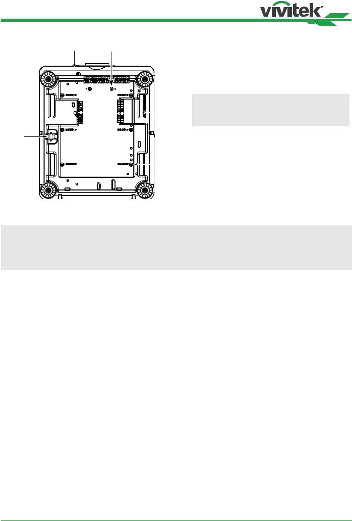
Bottom View |
10 |
IO Panel |
11 |
Control Panel |
12 |
Remote Control |
13 |
Remote Control Operating Range |
14 |
Installation and Setting up |
15 |
Inserting or Changing the Remote Control Batteries |
15 |
Installing the projector |
16 |
Precautions for Installation |
16 |
Mounting the projector |
17 |
Installing or Removing the Optional Lens |
18 |
Install New Lens |
18 |
Removing the Existing Lens |
19 |
Selecting the Input Voltage of AC Power |
20 |
Connecting to AC Power Supply |
20 |
Turning on the Projector |
20 |
Turning off the Projector |
21 |
Setting up the installation condition |
22 |
Setting up the Projection Mode |
22 |
Adjusting Projected Image Position |
23 |
Adjusting the Focus and Zoom |
23 |
Adjusting Geometric Distortion |
24 |
Keystone |
24 |
Rotation |
25 |
Pincushion / Barrel |
25 |
Arc |
26 |
Corner Adjustment |
27 |
Top Left Corner |
27 |
Top Right Corner |
27 |
Bottom Left Corner |
28 |
Bottom Right Corner |
28 |
Preventing the Unauthorized Use of the Projector |
29 |
Using the Control Panel Lock |
29 |
Locking the control buttons |
29 |
Unlocking the control panel |
30 |
Using Security Lock |
30 |
Enable the Security Lock |
30 |
Unlocking the projector |
31 |
Using Control ID for Multi-projector Application |
32 |
Step1: Set the Projector identification number |
32 |
Step2: Set the identification number of remote control |
33 |
Erase the identification number of the remote control |
33 |
Checking the identification number of the projector and re- |
|
mote control |
34 |
I/O - Connecting |
35 |
Connecting to Personal Computer |
35 |
Connecting to the Video Device |
35 |
Connecting to the Control Equipment |
36 |
HDBaseT/LAN (Network control) |
36 |
RS-232 (RS-232 control) |
36 |
Wired remote control |
36 |
3D Sync Out/In |
36 |
Connecting to the Screen Trigger |
37 |
Connecting to external HDBaseT Transmitter |
38 |
Using the projector |
39 |
Using On-Screen Display |
39 |
Using the OSD Menu |
39 |
Navigating the OSD |
39 |
Menu Tree |
40 |
INPUT |
40 |
PICTURE |
40 |
ALIGNMENT |
41 |
CONTROL |
42 |
SERVICE |
42 |
OSD Menu – INPUT |
43 |
Input Selection |
43 |
PIP |
44 |
Position |
44 |
Auto Source |
44 |
Color Space |
45 |
Aspect Ratio |
45 |
Overscan |
45 |
VGA Setup |
45 |
Test Pattern |
45 |
3D |
45 |
Auto Sync |
46 |
OSD Menu – PICTURE |
47 |
Picture Mode |
47 |
Brightness |
47 |
Contrast |
47 |
Saturation |
47 |
Hue |
47 |
Sharpness |
47 |
Color Temperature |
47 |
Color Gamut (Цветовая гамма) |
48 |
Gamma |
48 |
Input Balance |
48 |
HSG |
48 |
Noise Reduction |
48 |
Dynamic Black |
48 |
Light Off Timer |
48 |
2
UM81950823EN02

DU8195Z Series DLP Projector - User Manual
OSG Menu – ALIGNMENT
Lens Lock
Lens Control
Lens Type Lens Memory
Center Lens
Digital Zoom
Warp
Blanking Edge Blend
Screen Format
OSD Menu – CONTROL
Language
Projection Mode
High Altitude
Auto Power Off
Auto Power On Network
Light Power
Startup Logo
Infrared Remote
Trigger
OSD Settings
Image Latency
OSD Menu – SERVICE
Model
Serial Number
Software Version 1 / Software Version 2
Display the software version in the projector. Control/Remote ID
Active Source
Signal Format
H/V Refresh Rate
Pixel Clock
Light Time Constant Brightness Thermal Status
Factory Reset
49 |
Additional Information |
58 |
|
49 |
Product Specification |
58 |
|
49 |
Supported Signal Input Timing |
59 |
|
49 |
2D formats |
59 |
|
50 |
|||
Supported 3D Signal |
61 |
||
50 |
|||
Configurations of Terminals |
62 |
||
50 |
|||
DVI-D Terminal |
62 |
||
51 |
|||
VGA Terminal ( D-sub 15 pin) |
62 |
||
51 |
|||
HDMI(19 pin Type A) |
62 |
||
52 |
|||
Serial Control Termina |
|
||
52 |
|
||
(RS-232, D-sub 9 pin) |
62 |
||
53 |
|||
Screen Trigger |
63 |
||
53 |
|||
Wired Remote |
63 |
||
53 |
|||
HDBaseT/LAN Terminal |
63 |
||
53 |
|||
3D Sync Out |
63 |
||
54 |
|||
Lens Series |
64 |
||
54 |
|||
Product Dimensions |
65 |
||
54 |
|||
LED Indication |
66 |
||
55 |
|||
55 |
Power LED |
66 |
|
Status LED |
66 |
||
55 |
|||
Light Source LED |
66 |
||
56 |
|||
Temp LED |
66 |
||
56 |
|||
Common Problems and Solutions |
67 |
||
56 |
|||
57 |
Tips for Troubleshooting |
67 |
|
57 |
Image Problems |
67 |
|
Projection Problems |
68 |
||
57 |
|||
Remote Control Problems |
68 |
||
57 |
|||
Projection Lens Problems |
68 |
||
57 |
|||
Remote communication Problems |
68 |
||
57 |
|||
Having the Projector Serviced |
68 |
||
57 |
|||
57 |
About the Vivitek Support |
69 |
|
57 |
|||
North America |
69 |
||
57 |
|||
Europe and Africa |
69 |
||
57 |
|||
China |
69 |
||
57 |
|||
Asia and Taiwan |
69 |
||
57 |
|||
|
|
||
57 |
|
|
3
UM81950823EN02

DU8195Z Series DLP Projector - User Manual
Copyright
Copyright
The User’s Manual (including all pictures, illustrations and software) is protected by the international copyright right law. All rights are reserved. No duplication of the manual or any content included in the manual is allowed without the written consent of the manufacturer.
Vivitek is the trademark of Vivitek Corporation. ©All rights reserved. 2019.
Disclaimer
The information in the manual is subject to change without notice. The manufacturer does not provide any statement or warranty of the contents in the manual and clearly give up the implied warranties of merchantability and of fitness for a particular purpose. The manufacturer reserves the rights to modify the publication and change the contents of the materials at any time without notice to any person.
About the Manual
The manual describes how to install and use the projector and is applicable to the end-user. Relevant information (such as illustrations and descriptions) is put on the same page as possible as we can. The format, easy for printing, is convenient for reading and paper-saving which is beneficial to environmental protection. It is suggested printing the page you need.
4
UM81950823EN02
DU8195Z Series DLP Projector - User Manual
Important Safety Guidelines
Thank you for purchasing this product!
Read the Manual carefully to obtain the best performance. The Manual provides instructions to use the menu and implement operation.
Safety Notification
CAUTION
Suggest when turn off main power, also unplug the power cord from power outlet.
CAUTION
To prevent electric shock, do not open the cabinet. There are high-voltage components inside.
Refer service to qualified service personnel.
CAUTION
The symbol warns the user about electric shock caused by voltage not insulated. Therefore, it is dangerous to make any kind of contact with any parts of inside units.
To prevent the projector from electrical discharge or electric shock, do not expose the projector to rain or moist environment. Do not use the plug with an extension cord or an outlet unless all the prongs can be fully inserted.
This symbol alerts the user that important information which should be read carefully to avoid problems concerning the operation and maintenance.
WARNING TO CALIFORNIA RESIDENTS:
Handling the cables supplied with this equipment might expose user to a little lead, a chemical known to the Stage of California, resulting in risks of barrenness. Please remember to wash hands after handling.
NOTIFICATION (CANADA)
This Class A digital equipment complies with Canadian ICES-003.
CE NOTIFICATION
This is a Class A product, which complies with rules for CE marking. This product may cause radio interference that the user may be supposed to take adequate measures.
FCC NOTIFICATION
This device complies with part 15 of the FCC Rules. Operation is subject to the following two conditions:
(1)This device may not cause harmful interference;
(2)This device must accept any interference received, including interference that may cause undesired operation. This equipment has been tested and found to comply with part 15 of the FCC Rules. These requirements are designed to provide reasonable protection against harmful interference when the equipment operates in a commercial environment. This equipment might generate radio frequency energy. If user does not install or use in accordance with the instructions in manual, the radio frequency energy may interfere radio reception. If the above scenario occurs, the user may be responsible to correcting the interference.
WARNING!
Changes or modifications without approval from Vivitek could void the user’s authorization to operate the product.
5
UM81950823EN02
DU8195Z Series DLP Projector - User Manual
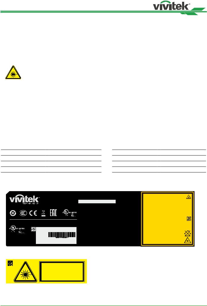
LIGHT MODULE
•A light module containing multiple laser diodes acts as the light source in the product.
•These laser diodes are sealed in the light module. It is recommended to ask dealer for maintenance or repair services of the light module.
•End user is not allowed to replace the light module.
•Contact distributor who provides the qualified service for light module replacement and further information.
LASER SAFETY NOTIFICATION AND CAUTION
Do not stare at the lens while in use
•CLASS 3R LASER PRODUCT
•This Laser Product is designated as Class 3R during all procedures of operation.
•LASER LIGHT - AVOID DIRECT EYE EXPOSURE.
•Do not point laser or allow reflected laser light toward other people or reflective objects.
•Direct or scattered light can be hazardous to eyes and skin.
•There is a potential hazard of eye exposure to laser radiation if the included instructions are not followed.
•Caution – use of controls, adjustments or performance of procedures other than those specified herein may result in hazardous radiation exposure.
The safety distance for this projector is 3.5 meters
Laser Parameters
Wavelength |
: |
450nm - 460nm (Blue) |
Total internal power |
: >100W |
Mode of operation |
: |
Pulsed, due to frame rate |
Apparent source size |
: >10mm, at lens stop |
Pulse width |
: |
0.87ms (Blue) |
Divergence |
: >100 mili Radian |
Maximum laser energy |
: |
0.45mJ (Blue) |
|
|
Product Label
Manufacturer’s ID Label, Explanatory Label and Certification Statement Label
DLP Projector / Projecteur DLP ( / )
Model/Modèle/( / ) : DU8195Z8190Z -BK
AC INPUT/Entrée CA( / ) :  200-240 VAC 7.8A 50/60Hz
AC INPUT/Entrée CA( / ) :  100-130 VAC 11.5A 50/60Hz
EU contact address: |
Serial No.: |
|
n˚ de série.: |
|
|
Delta Electronics(Netherlands)B.V. |
|
|
Zandsteen 15, 2132MZ Hoofddorp, |
|
|
The NetherLands |
Index:00 |
M/F Date:2019.05.15 |
: ( ) |
Производитель: Дельта Электроникс Инк.
Made inChina/ : / :
3264659400 WJ XXXX
This device complies with part 15 of the FCC rules.
Operation is subject to the following two conditions:
(1)this device may not cause harmful interference, and
(2)this device must accept any interference received, including interference that may cause undesired operation.
CAN ICES-3(A) /NMB-3(A)
Caution : Do not open the cover. No user-serviceable parts inside Avertissement : ne pas ouvrir le couvercle. Le produit ne contient
aucune pièce interne réparable par l’utilisateur.
: ,
: ,
: A
Complies with FDA performance standards for lase products except for deviations pursuant to Laser Notice No. 50, dated June 24, 2007
LASER RADIATION |
|
|
AVOID DIRECT EYE EXPOSURE |
|
|
CLASS 3R LASER PRODUCT |
3R : 450-460 nm ( ) |
|
Emitted Wavelength : 450-460 nm (Blue) |
: 0.45 mJ ( ), |
|
max pulse energy : 0.45 mJ (Blue) |
: 0.87 ms ( ) |
|
Pulse duration : 0.87 ms (Blue) |
|
|
RAYONNEMENT LASER |
|
|
EXPOSITION DIRECTE DANGEREUSE |
|
|
POUR LES YEUX |
3R : 450-460 nm ( ) |
|
APPAREIL À LASER DE CLASSE 3R |
: 0.45 mJ ( ), |
|
longueur d'onde : 450-460 nm (Bleu) |
: 0.87 ms ( ) |
|
maximum énergie de impulsion : 0.45 mJ (Bleu) |
|
|
durée de impulsion : 0.87 ms (Bleu) |
|
|
GB 7247.1-2012 / IEC/EN 60825-1:2007 |
3262308400 |
|
CLASS 1 LASER PRODUCT |
PRODUIT LASER DE CLASSE 1 |
|
|
|
|
IEC/EN 60825-1:2014 |
IEC/EN 60825-1:2014 |
|
Warning ! Do not look into the beam. |
|
|
No direct eye exposure to the beam |
|
|
is permitted. |
RG3 |
|
RG3 |
|
|
3.5 |
|
|
Hazard Distance : 3.5m |
|
|
Avertissement ! Ne Pas Regarder |
|
|
Directement Dans Le Faisceau. |
|
|
L’exposition Directe Des Yeux Au |
RG3 |
|
Faisceau Est Interdite. |
|
|
RG3 |
3.5 |
Distance À Risque : 3.5m |
|
Hazard Warning Symbol and Aperture Label
3262162601
6
UM81950823EN02
DU8195Z Series DLP Projector - User Manual
Installation and Use Notices
1.Read and keep this manual properly.
2.Pay attention to all the noted warnings, and follow all the guidelines and descriptions in this manual.
3.Do not use the projector near water.
4.Do not install the equipment near the thermal sources, such as heaters, radiators, furnace, amplifiers, and any other equipment that may generate heat.
5.Be careful while holding the equipment or moving the trolley with projector to prevent the equipment from turning over.
6.Notice whether there is any parts with flaws after receiving the projector.
7.Please notice that the projector will not power on until the lens is fitted. The protection covering the lens should
be taken to install the lens.
8.Do not let any vent be obstructed.
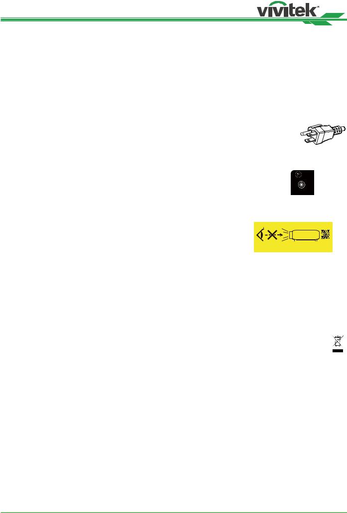
9.Do not destroy the safety protection function of polarized or grounding plug of power cord.
A polarized plug has one wide and one narrow blade. The plug has two blades and one grounding blade. The wide blade or grounding blade is provided for the safety concerns.
blade |
blade |
|
Grounding |
|
|
|
|
|
Narrow |
|
|
Wide |
blade |
|
|
|
|
If the plug provided does not match the outlet, please contact the electrician to change outlet.
10.The +12V trigger only outputs 12V DC trigger signal. Do not connect other power input or 
 output. Otherwise, the equipment may malfunction.
11.Adjust the slide switch with suitable volt input, and then plug in the projector; the red LED indicator would flash and then stabilize, getting into standby mode. User should only use the connectors or accessories provided by the manufacturer. Please refer to "Selecting the Input Voltage of AC Power on page20 ".
12.When user turns on the projector, the red LED indicator would flash until stabilize.
Do not look at the lens directly while the projector is running.
13.Install or use the projector, please do not look directly into the lens or the lens light output. The glare after focusing may cause damage to your eyes.
14.Unplug the power cord of the equipment if there is a thunderstorm or the equipment is not going to be used for a long time.
15.The packaging materials can be kept properly for transportation use afterwards.
16.If any breakdown occurs, please contact dealer or manufacture for qualified repair service.
3262199500
Do not look into the lens
Disposal of Old Electric and Electronic Equipment
The symbol on your product or the package represents that the product should not be treated as the normal household waste when discarded but should be carried to the recycling location of the waste electric and electronic equipment. The consequence on the environment and human health due to the incorrect disposal of the product can be prevented if it can be ensured that the product is properly discarded. Material recycling is helpful to the protection of natural resources. The symbol is only valid in European Union. If you want to discard electrical and electronic equipment, contact the governmental authorities or your dealer for the correct method of disposal.
Important Recycling Instructions
The product may contain other electronic wastes and may pose risk if not discarded properly. Abide by the local, state/ provincial or federal laws of recycling or discarding. For more information, please visit the website and contact Electronic Industries Alliance (EIA) on WWW.EIAE.ORG.
7
UM81950823EN02
DU8195Z Series DLP Projector - User Manual
Introduction
The User’s Manual describes the installation, setup and operation of the DU8195Z projector and provides assistance to the installation personnel and the end-user to fully develop the performance of the projector. VIVITEK has made every effort to ensure that the information in the Manual is correct at the time of printing. The contents may be frequently updated due to the continuously product improvement and customer feedback.
You can find the latest version of the Manual and the manual of other Vivitek products on www.vivitekcorp.com.
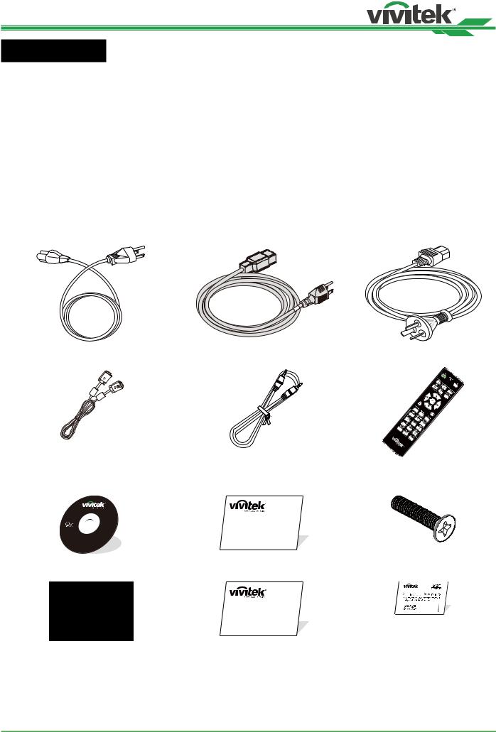
Packing Checklist
The following items are included in the packaging box of the DU8195Z projector. If any loss or damage to any item, contact your dealer or Vivitek customer service department.
Power Cord-USA 2 pieces |
Power Cord-EU |
Power Cord-China |
(Note : 110V*1, 220V*1) |
|
|
D-Sub Cable |
Wired remote cable |
IR Remote Control |
|
|
Anti-thief Screw (M4) |
User’s Manual Disc |
Limited Warranty (WW) |
(for Lens Installation) |
RoHS Card( China) |
Limited Warranty (CN) |
Certificate (China) |
China RoHS
8
UM81950823EN02

DU8195Z Series DLP Projector - User Manual
Projector Overview
Front-right View
1 2
3
4
1. Front IR Receiver
8The Receiver for IR signals from remote control.
2.LED Indicator
Display current projector status such as power, light source status and warning.
3.Air Intake
The fan pulls the cool air to the projector for system cooling.
4.Lens Release Button
Press the Lens Release button before removing the lens.
5.Lens hood
Remove the cover before installing the lens.
5
7 |
|
6. |
Height Adjuster |
6 |
Adjust level of projector |
7.Intake Vent
The fans pull air to cool the radiator of the projector.
8.Rear IR Receiver
The Receiver for IR signals from remote control.
Rear-right View
14
9 10 11 12 13
9.I/O Connector Panel
Connect to various input, control or output terminals to the projector. Refer to "IO Panel on page11 ".
10.Kensington Lock
Attach the projector to a permanent object with the Kensington slot and a security cable. (anti-theft function)
11.Slide Switch
Switch it to corresponding input voltage. Please refer to "Selecting the Input Voltage of AC Power on page20 "
12.AC Power Switch
Turn on/off the AC power of the projector.
13.AC Inlet
Connect the supplied power cable to this inlet.
14.Control Panel
Press the button to operate the OSD menu or adjust the lens Settings see OSD controls. Refer to "Control Panel on page12 "
Important
•The air passes through grill openings on the projector is for good air circulation. Do not obstruct any of the grill openings and keep the required distance from any object.
•The Kensington lock hole only provides connection to the Kensington cable. Please do not hang the projector or other objects with this Kensington hole.
9
UM81950823EN02
DU8195Z Series DLP Projector - User Manual
Bottom View
15 |
16 |
15. |
Anti-thief Screw hole |
|
|
|
The anti-thief screw can be fastened to prevent Lens |
|
|
|
removing by unauthorized person. |
|
|
16. |
Mounting Holes of Support Kit |
|
|
|
These two screws holes can be used to fix support |
|
|
|
kits of ultra-short throw lens. |
|
|
|
Note |
|
17 |
|
The screws are for Lens support kits only; over- |
|
|
|
loading may damage the projector or cause injury. |
19 |
|
17. |
Recess for projector handling. |
|
|
|
These four recesses can be used for handling the |
|
|
|
projector. |
|
18 |
18. |
Ceiling Mounting Hole |
|
|
|
Total 6 holes for M4 screw, maximum depth 14mm. |
|
|
19. |
Security Slot |
|
|
|
This hole can be locked with a safety chain after the |
|
|
|
ceiling mount installation is completed and provide |
|
|
|
Short-term protection |
Note
•With ceiling installation, refer to "Mounting the projector on page17 " for detail information.
•The security slot only provides short-term safety protection after installation. Please do not use this hole to hang the projector to avoid falling or personal injury.
10
UM81950823EN02
DU8195Z Series DLP Projector - User Manual
IO Panel
RS-232 |
V |
H |
B/Pb |
G/Y |
R/Pr |
|
VGA |
MONITOR OUT |
OUT |
|
|
|
|
|
|
|
|
|
|
TRIGGER |
|
|
|
|
|
|
|
|
3D |
|
|
|
|
|
|
|
|
SYNC |
|
|
|
|
|
|
|
|
|
|
|
|
|
|
|
|
|
|
SDI |
|
|
WIRED |
|
|
|
|
|
|
|
|
IN |
|
|
|
|
|
|
|
|
|
|
REMOTE HDBaseT/LAN |
HDMI I |
|
DVI-D |
|
|
IN |
OUT |
HDMI II |
|
TRIGGER(12V +/-1.5V)
When connected to the screen through a 3.5mm cable, the screen deploys automatically on startup of the projector. The screen reacts when the projector is powered off.
RS-232
The 9-pin D-sub interface is used to connect to the PC control system and projector maintenance.
Component (V, H, B/Pb, G/Y, R/Pr)
Connect RGBHV or Component signal from computer or component video enabled device
VGA
Provide the standard 15-pin VGA connection and can connect to RGB, HD Component or personal computer.
MONITOR OUT
WIRED REMOTE
Connect the supplied remote controller to the projector
HDBaseT/LAN
Connect an Ethernet cable (Cat5e/Cat6, not supplied) from a computer, network device, or HDBaseT transmitter.
HDMI 1 / HDMI 2
High Definition Multimedia Interface, connect the HDMI cable from a computer or video device
DVI-D
Use the DVI-D cable to connect the DVI-D input port of the projector to the DVI-D output port of the video device.
SDI IN/OUT
Connect to SDI source.
Connect to a monitor to display the projected content. |
3D SYNC IN / Out |
|
Connect to the 3D IR synchronization signal transmitter. |
Note for Trigger
•When the projector is turned on, a control signal (DC 12V) outputs from this terminal.
•Do not use this jack for anything other than intended use.
Note for Wired Remote
•Please make sure whether the port for insertion is correct before the terminal of the wired remote control is inserted. The remote control may be damaged if inserted to the wrong port such as trigger. Do not use this jack for anything other than intended use.
•When the cable of the wired remote control is plugged into the projector, the projector will automatically switch to the wired control mode and turn off the wireless infrared receiving function. So before using the wireless infrared controller, make sure the cable of the wired remote is not plugged into the Wired Remote port.
11
UM81950823EN02

DU8195Z Series DLP Projector - User Manual
Control Panel
+ +
ENGER
- -
POWER
User the button to turn on/off the projector.
INPUT
Push the button to select the input signal. HDMI, DVI, VGA, Component…etc.
AUTO SYNC
Implement automatic signal synchronization.
ASPECT
Change the aspect ratio of the current image and push the button to change to the next aspect ratio settings.
MENU
Push the button to display or hide the OSD menu.
UP/Down/Left/Right
Use the button to select the OSD option.
ENTER
Use the button to select settings or confirm the changed settings.
EXIT
Push the button to return to the menu on the previous level or exit the OSD menu.
CENTER LENS
Push the button to center the lens and calibrate the parameter of lens shift, focusing and zooming.
Note
The lens memory function requires the accurate lens adjustment parameter. Please center the lens every time after the lens is mounted.
Blank
Use the button to stop the projection temporarily
LENS SHIFT
Use these four buttons to move the projected image to desired position.
Note
If the projected screen is too different with the projected position by user setting, please move the projector or adjust the four adjustment feet of the projector to fix the approximate projection position. Then use Lens
Shift this function to finely adjust the projection position.
FOCUS
Use the button to adjust the focus of projected image.
ZOOM
Use the button to zoom in/out the projected image.
12
UM81950823EN02

DU8195Z Series DLP Projector - User Manual
Remote Control
ENTER
MENU |
EXIT |
AUTO PC BLANK |
STATUS |
VGA COMPONENT ASPECT
1 2 3
HDMI1 HDMI2 DVI
4 5 6
3G-SDI Displayport HDBaseT
7 8 9
CLEAR |
FREEZE |
ID SET |
0
On |
Use the button to turn on the projector. |
|
|
OFF |
Use the button to turn off the projector. |
|
|
FOCUS |
Adjust the focus of the projected image. |
|
|
ZOOM |
Zoom in/out the projected image. |
|
|
TEST PATTERN |
Use the button to show the test pattern. Press this but- |
|
ton again to switch to the next pattern. Press the EXIT |
|
button to return to the projected image. |
|
|
LENS SHIFT |
Use the button to move the lens right or left. |
|
|
ENTER |
Use the button to select settings or confirm the changed |
|
settings. |
|
|
MENU |
Press the button to display or hide the OSD Menu. |
|
|
EXIT |
Press the button to return to the previous Menu or exit |
|
the OSD Menu. |
|
|
AUTO PC |
You can use this function to execute signal source auto |
|
synchronization |
|
|
BLANK |
Press the button to temporarily interrupt the projection. |
|
|
STATUS |
Show OSD MENU – SERVICE. |
|
|
VGA |
Select VGA input source. |
|
|
COMPONENT |
Select Component (V, H, B/Pb, G/Y, R/Pr) input source. |
|
|
ASPECT |
Press the button to display aspect ratio options. |
|
|
HDMI1 |
Select HDMI 1 input source. |
|
|
HDMI2 |
Select HDMI 2 input source. |
|
|
DVI |
Select DVI input source. |
|
|
3G-SDI |
Select 3G-SDI input source. |
|
|
DisplayPort |
Select DisplayPort input source. (Not available for this |
|
model) |
|
|
HDBaseT |
Select HDBaseT input source. |
|
|
CLEAR |
Erase the set ID number of the remote control; refer to |
|
"Erase the identification number of the remote control |
|
on page33 " |
FREEZE |
Freeze the projected image or resume the projection. |
|
|
ID SET |
Set up ID number for remote control; refer to "Using |
|
Control ID for Multi-projector Application on page32 ". |
Wired Remote Jack Connect to WIRED REMOTE terminal on the projector
13
UM81950823EN02
DU8195Z Series DLP Projector - User Manual
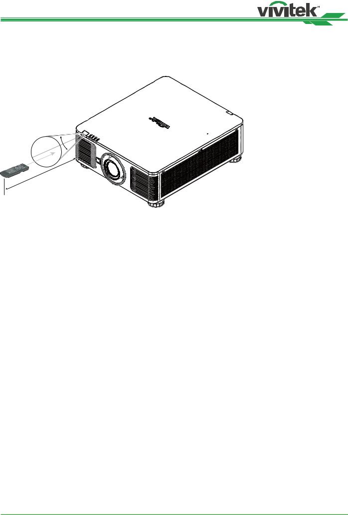
Remote Control Operating Range
The remote control uses infrared transmission to control the projector. It is not necessary to point the remote directly at the projector. Provided you are not holding the remote perpendicular to the sides or the rear of the projector, the remote will function well within a radius of about 10 meters (25 feet) and 15 degrees above or below the projector level. If the projector does not respond to the remote control, move a little closer.
±30°
10m
14
UM81950823EN02
DU8195Z Series DLP Projector - User Manual
Installation and Setting up
Inserting or Changing the Remote Control Batteries
1 |
2 |
3 |
1.Remove the battery compartment cover by sliding the cover in the direction of the arrow.
2.Place two AA batteries with the correct polarity.
3.Slide on the cover as the arrow in the illustration.
Important
•Avoid using the projector with bright fluorescent lighting turned on. Certain high-frequency fluorescent lights can disrupt remote control operation.
•Be sure nothing obstructs the path between the remote control and the projector.
•Do not expose the remote control to high temperature or humidity; otherwise, the remote control will not work functionally.
Battery installation instructions
•Make sure the battery is installed with the correct polarity.
•Do not use the old and new batteries or the batteries of different types together
•Remove the battery if the remote control may not be used for a long time to prevent the damage caused by leaks.
15
UM81950823EN02

DU8195Z Series DLP Projector - User Manual
Installing the projector
The high quality display effect can be guaranteed only when the projector is correctly installed. Generally, the light source facing the screen should be reduced or eliminated as much as possible. The contrast of the image will be obviously reduced if the light directly shines on the screen, such as the beam from windows or the searchlight cast on the image. The image may become faded and not bright.
Precautions for Installation
Caution
•Projector installation must be done by a qualified professional. Contact your dealer for more information. It is not recommended you install the projector yourself.
•With ceiling installation, use approved mounting hardware & M4 screws; maximum depth of screw: 14 mm. Contact your dealer for information about mounting the projector on a ceiling.
•Only use the projector on a solid, level surface, serious injury and damage can occur if the projector is dropped.
Caution
•Ensure that the hot air from the exhaust vent is not sucked into the projector. Because even the ambient is within the operating temperature range, the hot air will cause the projector not dissipate heat well and cause the projector internal temperature too high. Make projector enter to protection mode.
•Ensure the air intake and exhaust vents are unobstructed and keep the required distance from any object.
Below is required minimum distance between the vent and any object.
•All added enclosures should pass a certified thermal evaluation to ensure that the projector does not recycle exhaust air, as this may cause the projector to shut down even if the enclosure temperature is with the acceptable operation temperature range.
Airflow and Heat Emission |
Minimum Distance to Vent |
50cm  50cm
50cm
50cm |
50cm |
Caution
Please do not stack the projector on the surface of another projector, serious injury and damage may occur if the projector is dropped
16
UM81950823EN02

DU8195Z Series DLP Projector - User Manual
Mounting the projector
For mounting the projector, please use UL Listed ceiling mounts and M4 screws, maximum depth of screw: 14 mm.
17
UM81950823EN02

DU8195Z Series DLP Projector - User Manual
Installing or Removing the Optional Lens
Caution
•Do not shake or place excessive pressure on the projector or the lens components as the projector and lens components contain precision parts.
•When shipping the projector with the optional lens, remove the optional lens before shipping the projector. The lens and the lens shift mechanism may encounter damage caused by improper handling during transportation.
•Before removing or installing the lens, be sure to turn off the projector and wait till the cooling fans stop, and turn off the main power switch.
•Do not touch the lens surface when removing or installing the lens.
•Keep fingerprints, dust or oil away from the lens surface. Do not scratch the lens surface.
•Work on a level surface with a soft cloth under it to avoid scratching.
•If you remove and store the lens, attach the lens cap to the projector to keep off dust and dirt.
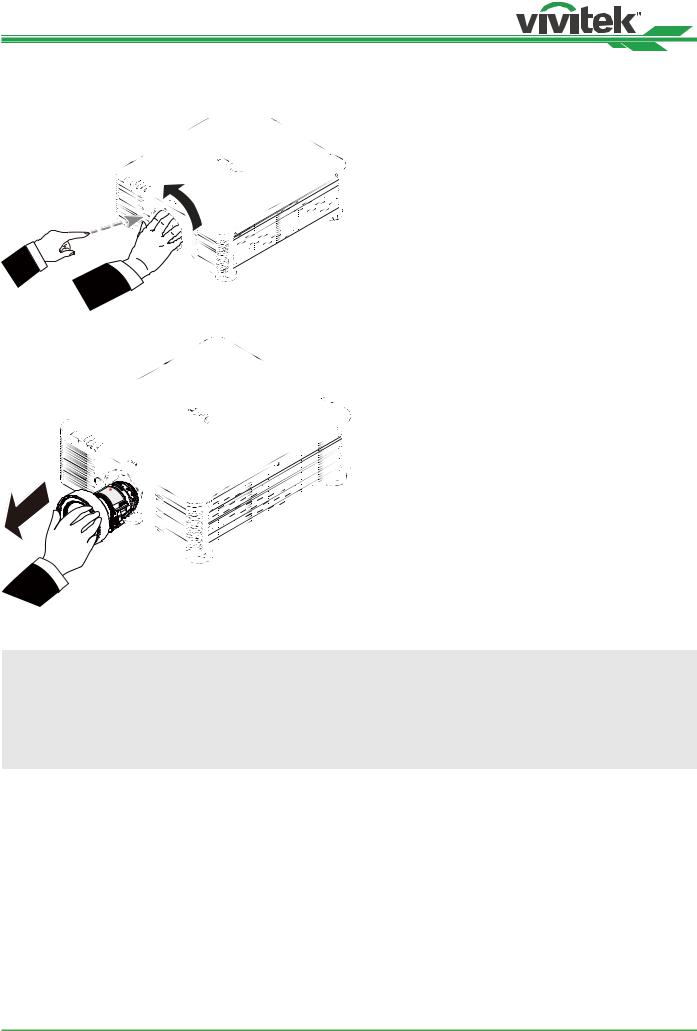
Install New Lens
1. If the Lens cover is installed, pull the edge of the lens cover with one hand ( ), so that the lens cover can be removed easily with the other hand (  )
)
1
2. Align the “ “ symbol on the lens label with the “ * |
Arrow up |
“ symbol on the top of the body (align to the center |
|
of the lens hole) and pull in the lens. |
|
3.Make sure the lens is pushed into the holder and turn it clockwise to the “Lock” position. When turning the lens, the “Click” sounds twice to indicate that the lens is completely fixed.
4.Check if the lens is fixed successfully by pulling the lens out of the holder gently.
Note
The lens memory function requires the accurate lens adjustment parameter. Please center the lens every time after the lens is mounted.
18
UM81950823EN02
DU8195Z Series DLP Projector - User Manual
Removing the Existing Lens
5.Push the LENS RELEASE button all the way in and rotate the lens counterclockwise. The existing lens will be disengaged
6. Pull out the existing lens slowly.
Caution
•When installing the lens into the projector, be sure to remove the lens cap from the back of the optional lens before installing the optional lens into the projector. Failure to do so will cause damage to the projector and lens.
•There is one safety switch inside the lens slot on the projector to prevent unexpected injury by laser beam, the projector cannot be turned on if the projection lens has not been installed or is not installed correctly. Please make sure the lens is installed properly before tuning on the projector.
19
UM81950823EN02

DU8195Z Series DLP Projector - User Manual
Selecting the Input Voltage of AC Power
There is one slide switch near AC switch, pleases switch it to corresponding input voltage of AC power. Please switch it to 115V if the input voltage range is 100V to 130V,
switch to 230V if input voltage range is 200V to 240V.
VOLTAGE SELECT
200~240 VAC
100~130 VAC
AC 100-130V
200-240 V~
100-130 V~
AC 200-240V
Important !
When the input voltage is 110V, the current supplied by the power supply does not provide the current required to run the projector at full power. In this case, the projector will automatically reduce the light
source power to 65%, and the projector light output will also be reduced to about 65% of the nominal brightness accordingly to ensure that the projector can operate normally
200-240 V~
100-130 V~
Connecting to AC Power Supply
The AC power cord is included in the box; plug the power cord to the AC socket on the IO panel.
Turning on the Projector
Once the projector is correctly located and the power cable and other connections are in place, it is important that the projector is correctly powered on in order to avoid damage to components and un-necessary wear and tear. Refer to the following guide to power on the projector.
1.Press the main power switch to the on ( I ) position as shown. POWER LEDs flashes then lights red.
POWER |
STATUS |
LIGHT |
.TEMP |
VOLTAGE SELECT
200~240 VAC
100~130 VAC
I
O
2.Press the POWER button on the control panel or ON button on the remote control.
AUTO
POWER INPUT SYNC ASPECT
MENU |
EXIT |
20
UM81950823EN02
DU8195Z Series DLP Projector - User Manual
3.The Power LED and LIGHT LED flashes green till power on process is finished.
4.After few seconds, both LEDs keep green, the projector is ready for use.
POWER |
STATUS |
LIGHT |
.TEMP |
||
|
|
|
|
|
|
|
|
|
|
|
|
POWER |
STATUS |
LIGHT |
.TEMP |
||
|
|
|
|
|
|
|
|
|
|
|
|
Turning off the Projector
Once the projector is no longer required, it is important to shut it down correctly to avoid damage or unnecessary wear and tear to the projector.
Note
•Do not unplug the power cable from the wall outlet or projector when the projector is powered on. Doing so can cause damage to the AC IN connector of the project or the prong plug of the power cable. To turn off the AC power supply when the projector is powered on, use a power strip equipped with a switch and a breaker.
•Do not turn off the AC power supply within 10 seconds after making adjustment or changing the setting. Doing so is possible to cause loss of adjustments and settings and return to default.
Refer to the following guide to shut down the projector.
1.Press the POWER button on the control panel or OFF button on the remote control once, the Power Off window displays.
2.Press the POWER button again on the OSD control panel or remote control to verify power off, the power LED flashes orange after Power Off is confirmed.
3.The projector enters SAVING mode when the power LED lights red.
4.Press the Main Power switch to the off position (O) to turn off the projector.
I
O
AUTO
POWER INPUT SYNC ASPECT
MENU |
EXIT |
21
UM81950823EN02
Loading...