

Visara VI-5990A, VI-5990L Installation And Configuration Manual

VI-5990A/L Virtual Tape Appliance/Library
Installation and Configuration Manual
P/N 707166-001


VI-5990 Installation and Configuration Manual
Revision Information
Issue/Revision Schedule
Comments Revision Number Date
Initial Release 707166-001 12/11/14
707166-001 iii


VI-5990 Installation and Configuration Manual
Table of Contents
Revision Information.........................................................................................................iii
Table of Contents.................................................................................................................v
Chapter 1. VI-5990 Installation ....................................................................................... 1-1
VI-5990A Product Overview......................................................................................1-1
VI-5990L Product Overview ...................................................................................... 1-2
VI-5990A/L.................................................................................................................1-2
Initial Installation........................................................................................................ 1-3
Chassis Installation ..................................................................................................... 1-3
Rack Installation ......................................................................................................... 1-6
Cabling the VI-5990A for Power................................................................................ 1-8
Cabling the VI-5990L for Power................................................................................1-8
Cabling for FICON.....................................................................................................1-9
Cabling for Ethernet.................................................................................................. 1-10
Local Console Control..............................................................................................1-11
Editing the VTA.ini File...........................................................................................1-12
Powering up the VI-5990.......................................................................................... 1-13
Chapter 2. Configuration Overview................................................................................. 2-1
Initial Configuration of the VI-5990........................................................................... 2-2
Initial Connection Panel.............................................................................................. 2-3
Login Panel.................................................................................................................2-4
VI-5990 Status Panel .................................................................................................. 2-5
Making Configuration Updates...................................................................................2-6
Network Options Panel............................................................................................... 2-7
Field Definitions .................................................................................................... 2-8
Button Definitions.................................................................................................. 2-9
Server Options Panel.................................................................................................2-10
Field Definitions .................................................................................................. 2-10
Button Definitions................................................................................................ 2-11
Security Options Panel.............................................................................................. 2-12
Changing Passwords............................................................................................2-12
Enable/Disable Network Services........................................................................2-13
Button Definitions........................................................................................... 2-13
Tape Pools................................................................................................................. 2-13
Tape Drives...............................................................................................................2-13
Save/Restore Configuration Panel............................................................................2-14
Booted Configuration...........................................................................................2-15
Current Configuration..........................................................................................2-15
Default Configuration.......................................................................................... 2-15
Copying the Current Configuration to a File....................................................... 2-16
Creating a New Default Configuration................................................................ 2-16
Deleting a Configuration......................................................................................2-16
707166-001 v

Activating a Stored Configuration....................................................................... 2-17
Copy the Current Configuration to a USB Drive.................................................2-17
Copy Configuration Files from a USB Drive...................................................... 2-18
Chapter 3. Configure Tape Pools..................................................................................... 3-1
Field Definitions ......................................................................................................... 3-2
Button Definitions....................................................................................................... 3-4
Chapter 4. Configure Tape Drives................................................................................... 4-1
Configuring LPARs.................................................................................................... 4-2
Field Definitions .................................................................................................... 4-3
Button Definitions.................................................................................................. 4-3
Configuring Path’s...................................................................................................... 4-4
Field Definitions .................................................................................................... 4-4
Button Definitions.................................................................................................. 4-5
Configuring Tape CU’s Panel..................................................................................... 4-6
Field Definitions .................................................................................................... 4-6
Button Definitions.................................................................................................. 4-7
Chapter 5. Configure HBA Interface............................................................................... 5-1
Chapter 6. Configure Infiniband Interface.......................................................................6-1
Chapter 7. Configure for iSCSI .......................................................................................7-1
vi 707166-001

VI-5990 Installation and Configuration Manual
Chapter 1. VI-5990 Installation
The purpose of this manual is to document the VI-5990A Virtual Tape Appliance and
VI-5990L Virtual Tape Library, providing specifics and procedures related to the
installation and configuration of these products.
VI-5990A Product Overview
The Visara VI-5990A Virtual Tape Appliance provides an interface between one or more
host mainframe systems and data storage, usually hard drive storage. It is called a Virtual
Tape Appliance because it appears to the host(s) as if it were one or more IBM 3490 or
IBM 3590 tape controllers. The VI-5990A may appear as if it were as many as sixteen
different tape controllers, with each tape controller having up to sixteen virtual tape
drives. Fully configured the VI-5990 may appear to have as many as 256 (virtual) tape
drives. Data storage used by the VI-5990A is external. Storage may be interfaced through
Host Bus Adapters (HBAs), Infiniband Adapters, or through Ethernet iSCSI. Two built in
10 Gbps Ethernet interfaces may be configured to be used with iSCSI.
The VI-5990A is housed in an enterprise class 3U server which may be installed in any
standard 19” rack, and comes with dual processors, dual redundant hot-swappable power
supplies, and two 10Gbps Ethernet interfaces. Each power supply is capable of
completely running the platform. A pair of hard drives, set up in a mirrored-RAID
configuration supports the Linux operating system and VI-5990 server software. Failure
of a single hard drive is permissible without interrupting the operation of the platform.
Five hot-swappable fans provide cooling.
Hardware monitoring of the power supplies, hard drives, fans, and cooling can be viewed
through a browser connection. Optionally you may configure the VI-5990A to generate
emails to warn of the same hardware failures if they were to occur.
Configuration and management of the platform is performed through a secure browser
connection (HTTPS), through either a locally-attached console (directly attached
keyboard, mouse, and monitor), or remotely through an Ethernet connection. The
VI-5990A ships with a default configuration including a default IP address.
Once configured, the VI-5990A is capable of running independently, without human
intervention. That is, if power is lost and regained, it will automatically boot back into
service using the stored configuration. You can manage the platform using the same
secure web browser connection from anywhere. Multiple management console interfaces
are supported by the VI-5990A.
707166-001 1-1

Chapter 1. Installation
VI-5990L Product Overview
The Visara VI-5990L Virtual Tape Library provides an interface between one or more
host mainframe systems and data storage, usually hard drive storage. Like the VI-5990A
it appears to the host(s) as if it were one or more IBM 3490 or IBM 3590 tape controllers.
The VI-5990L may appear as if it were as many as sixteen different tape controllers, with
each tape controller having up to sixteen virtual tape drives. Fully configured the VI-5990
may appear to have as many as 256 (virtual) tape drives. Data storage used by the
VI-5990L can be internal or external. Up to 120 TB of local storage may be installed
directly on the VI-5990L. External storage may be interfaced through Host Bus Adapters
(HBAs), Infiniband Adapters, or through Ethernet iSCSI. Two built in 10 Gbps Ethernet
interfaces may be configured to be used with iSCSI.
The VI-5990L is housed in an enterprise class 4U server which may be installed in any
standard 19” rack, and comes with dual processors, dual redundant hot-swappable power
supplies, and two 10Gbps Ethernet interfaces. Each power supply is capable of
completely running the platform. A pair of hard drives, set up in a mirrored-RAID
configuration supports the Linux operating system and VI-5990 server software. Failure
of a single hard drive is permissible without interrupting the operation of the platform.
Seven hot-swappable fans provide cooling.
Hardware monitoring of the power supplies, hard drives, fans, and cooling can be viewed
through a browser connection. Optionally you may configure the VI-5990L to generate
emails to warn of the same hardware failures if they were to occur.
Configuration and management of the platform is performed through a secure browser
connection (HTTPS), through either a locally-attached console (directly attached
keyboard, mouse, and monitor), or remotely through an Ethernet connection. The
VI-5990L ships with a default configuration that includes a default IP address.
Once configured, the VI-5990L is capable of running independently, without human
intervention. That is, if power is lost and regained, it will automatically boot back into
service using the stored configuration. You can manage the platform using the same
secure web browser connection from anywhere. Multiple management console interfaces
are supported by the VI-5990L.
VI-5990A/L
Since the VI-5990A and VI-5990L run the same basic software and function very
similarly, they will collectively be referred to as the VI-5990 throughout this manual,
unless specifics to one model or the other need to be made.
1-2 707166-001

VI-5990 Installation and Configuration Manual
Initial Installation
Installation of the VI-5990 consists of multiple steps, and may involve more than one
person. The VI-5990 can be locally or remotely configured. Tasks required to complete
an installation include:
1. Mounting the hardware platform (if desired) in a rack or placing the platform
within the necessary proximity of all of the network connections required to
satisfy the configuration. The VI-5990A requires a 3U space when mounted in
a rack, and the VI-5990L requires a 4U space.
2. Cabling the unit for power, FICON, and Ethernet connections as needed.
Locally configuring:
3. Attach monitor, mouse, and keyboard directly to the unit.
4. Once booted, select Start>Programs>Firefox.
Remotely configuring:
3. Editing the VTA.ini file if necessary to provide access to a web browser
capable platform, such as a PC, or change the IP address on a web browser
capable platform to be compatible to the VI-5990 default address.
4. Powering up the unit with a USB drive containing the VTA.ini file.
5. Connect to the platform with a web browser to finish the configuration.
Chassis Installation
Tools needed:
1. Phillips Screw Driver
2. Antistatic Strap
Installing Chassis Rails:
Please make sure that the chassis covers and chassis rails are installed on the chassis
before you install the chassis into the rack.
To avoid personal injury and property damage, please follow all the safety steps listed
below.
Before installing the chassis rails:
1. Enclose the chassis with chassis covers.
2. Unplug the AC power cord(s).
3. Remove all external devices and connectors.
707166-001 1-3
Chapter 1. Installation
Procedures to install chassis rails:
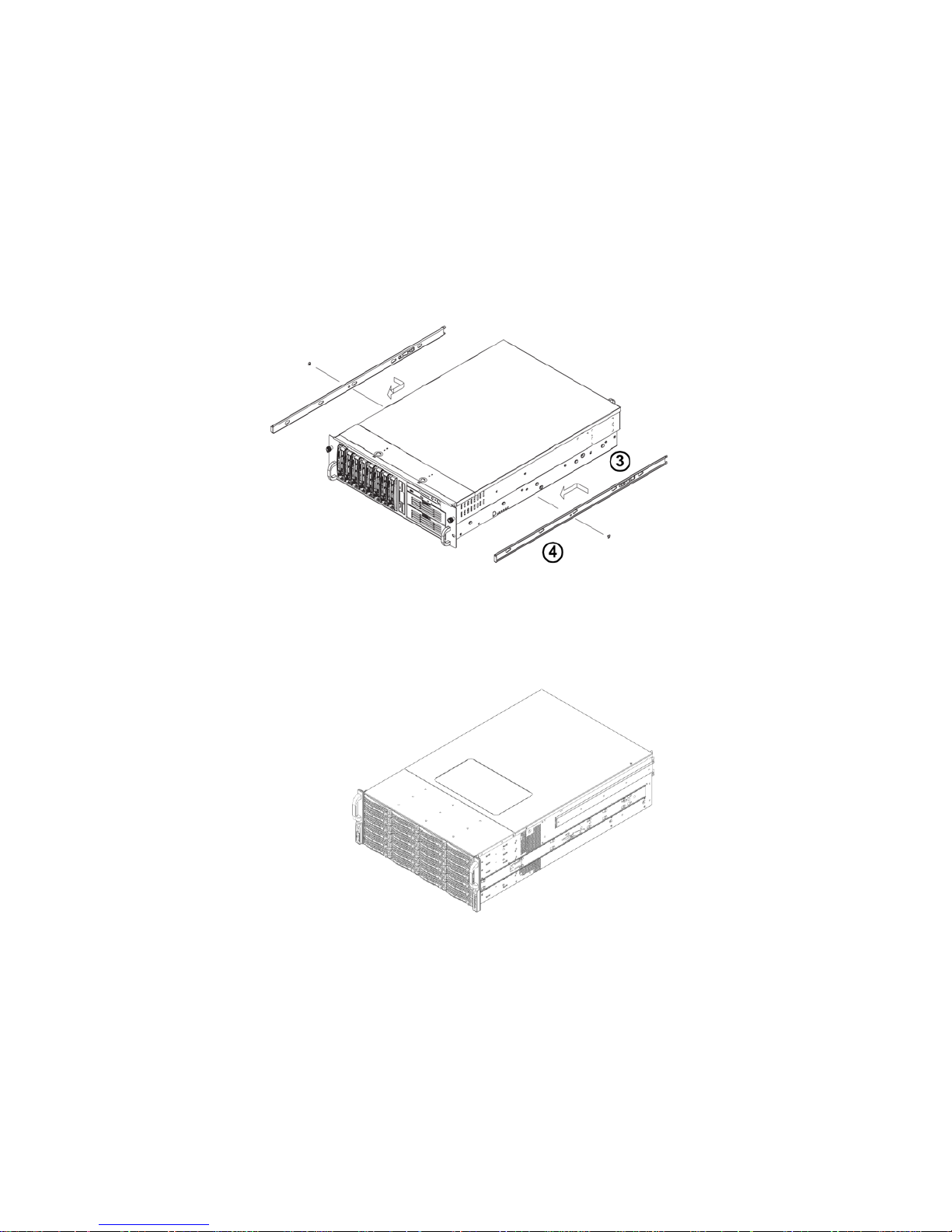
1. Included in the shipping package is a pair of rail assemblies. In each rail
assembly, locate the inner rail and the outer rail.
2. Press the locking tab to release the inner rail from its locking position and pull out
the inner rail from the rail assembly. (The inner rails are to be attached to the
chassis and the outer rails are to be installed in the rack.)
3. Locate the five rail buttons and each side of the chassis and locate the five
corresponding holes on each of the inners rails.
(Please note that one end of the hole is larger than the other end of the hole.)
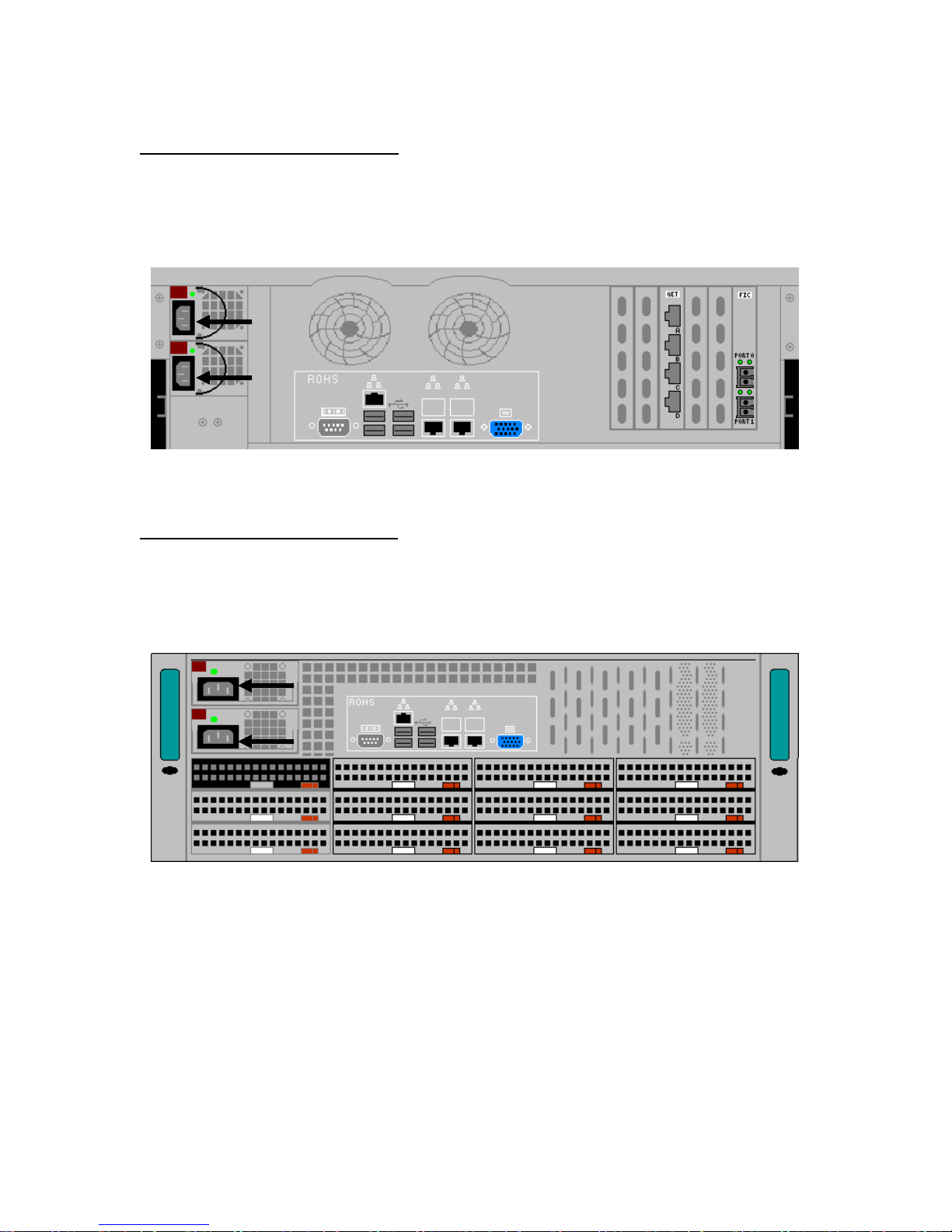
VI-5990A
VI-5990L
1-4 707166-001
VI-5990 Installation and Configuration Manual
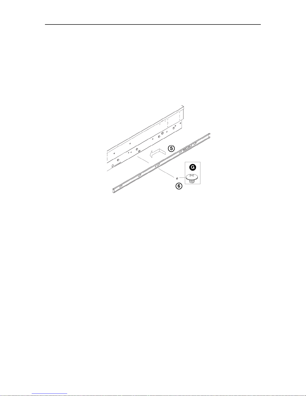
4. Align the larger end of each hole against its corresponding button. Once all
aligned, push the holes toward their corresponding buttons and the rail is placed
on the chassis.
5. Once the rail is placed on the chassis, pull the rail forward until the rail buttons
lock in the small ends of the corresponding holes.
6. Secure the rail to the chassis with a Type G screw. Repeat the above steps to
install the other rail on the chassis.
707166-001 1-5
Chapter 1. Installation
Rack Installation
After you have installed the inner rails on the chassis, you are ready to install the outer
rails of the rail assemblies to the rack.
(The rails are designed to fit in the racks with the depth of 28-33”.)
Procedure:
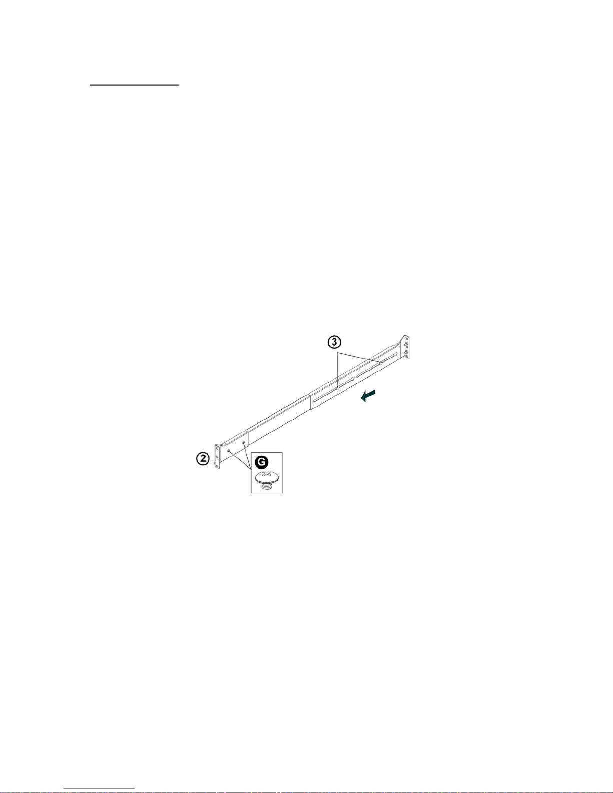
1. In the package, locate a pair of front (short) and rear (long) brackets. Please note
that the brackets are marked with Up/Front Arrows (front) and Up/Rear arrows
(rear).
2. Secure the front (short) bracket (marked with the Up/Front arrows) to the outer
rail with two Type G screws.
3. Locate the two buttons on the outer rail and attach the rear (long) bracket to it by
sliding the opening of the rear rail through the button.
4. Measure the depth of your rack and adjust the length of the rails accordingly.
5. Repeat the same steps to install the other outer rail on the chassis.
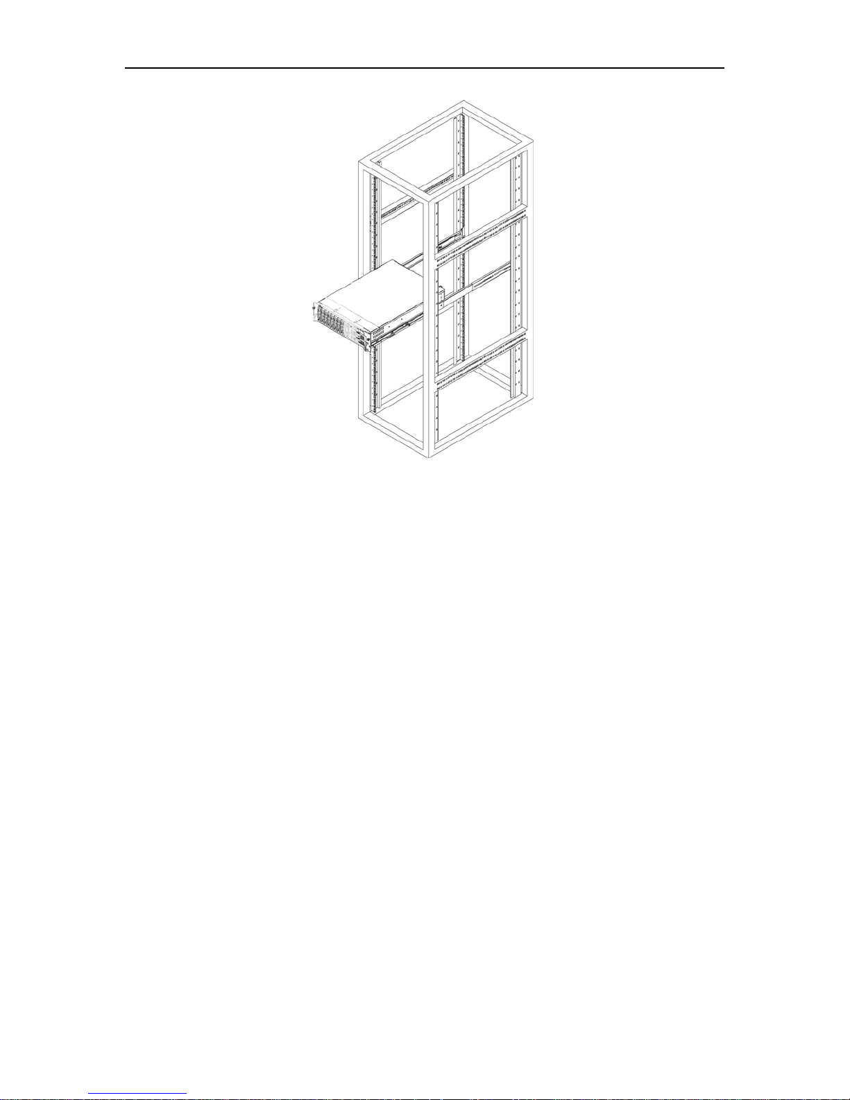
6. Secure both outer rail assemblies to the rack with Type H screws and Type I
washers.
7. Slide the server chassis into the rack from the front.
(The server may not slide into the rack smoothly or easily when installed the first
time. Some adjustments to the slide assemblies might be needed for easy
installation.)
8. You will need to release the safety taps on both sides of the chassis in order to
completely remove the chassis out of the rack.
1-6 707166-001
VI-5990 Installation and Configuration Manual
707166-001 1-7
Chapter 1. Installation
Cabling the VI-5990A for Power
The VI-5990A supports two hot-swappable power supplies. Each power supply requires a
separate power cord, which can be plugged into a separate properly grounded power
source if available. Each supply can provide the full power requirements for the unit.
Cabling the VI-5990L for Power
The VI-5990L supports two hot-swappable power supplies. Each power supply requires a
separate power cord, which can be plugged into a separate properly grounded power
source if available. Each supply can provide the full power requirements for the unit.
1-8 707166-001
VI-5990 Installation and Configuration Manual
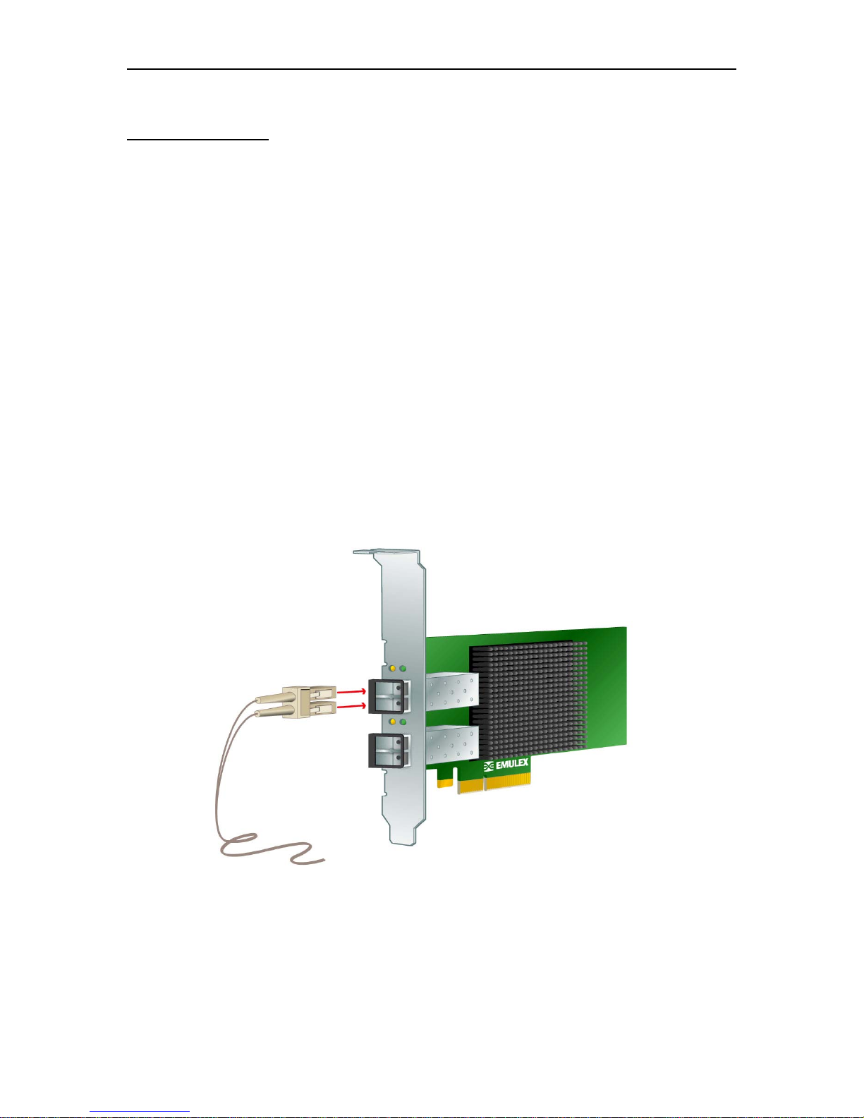
Cabling for FICON
The FICON interface cards used by the VI-5990 may have 1 or 2 individual FICON
interfaces built in. Up to two FICON cards may be installed. Each FICON interface
includes a transceiver mounted on the interface card. FICON transceivers come in short
wave and long wave versions. Correct transceivers for the customer’s environment
should have been shipped with the platform. However if the correct transceivers are not
installed, it is possible to swap transceivers in the field. Please refer to the VI-5990 Users
Guide and Maintenance Manual for information regarding this.
The FICON interface card ships with a plastic or rubber plug inserted into each FICON
interface, for purposes of keeping dust from the optical leads and to help protect the
connector during shipment. The plug(s) should be left in place until you are ready to
attach the FICON cable(s). When ready, remove each plug and set aside in a safe place
for future use. Insert the FICON cable into the cavity vacated by the plastic plug, and
push in until you hear/feel it click into place. Be careful when handling FICON cables,
and do not bend the cables any more than necessary. The cables are fiber optics, and
bending them too tightly will cause them to break internally, and make them useless.
707166-001 1-9
Chapter 1. Installation
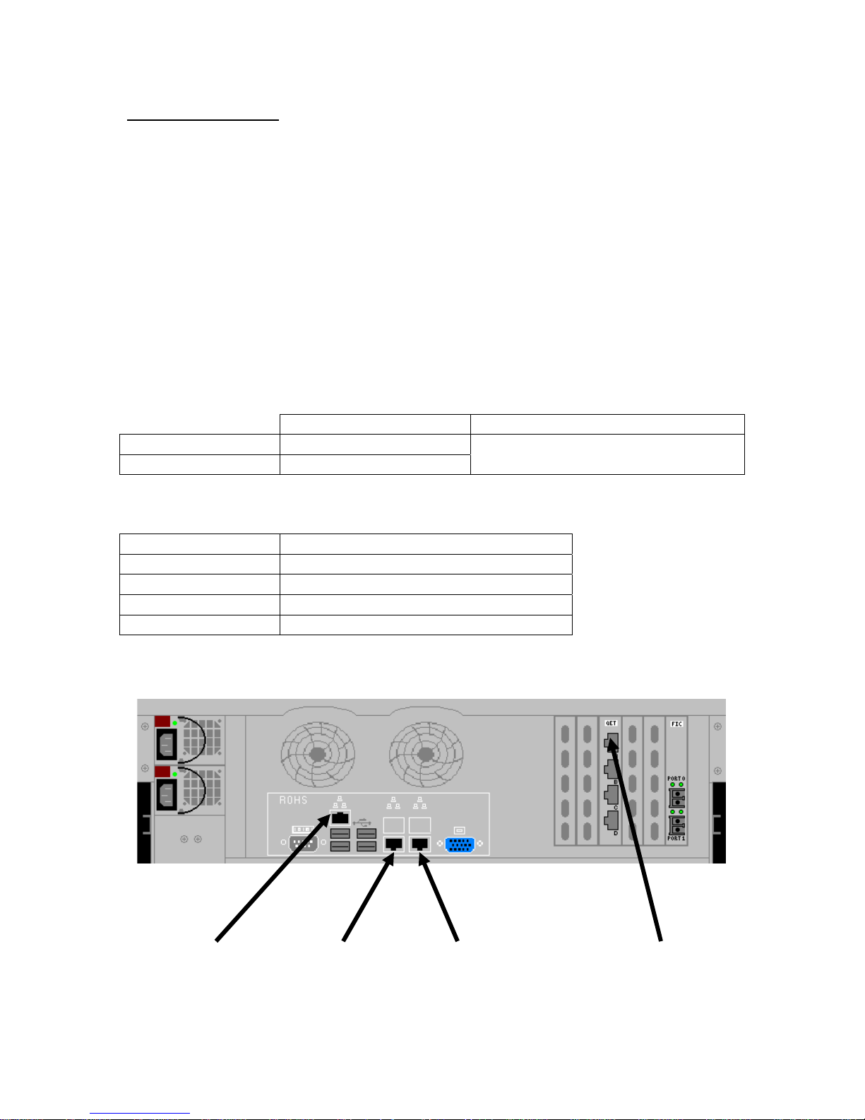
Cabling for Ethernet
The Ethernet interfaces for the VI-5990 each consist of an RJ45 socket. Plug a standard
Ethernet cable with an RJ45 jack mounted on the end, into the appropriate socket until
you feel it click into place. The Ethernet interface of the VI-5990 will default to autodetect the speed and can be plugged into a switch or hub running at 10 Mbps, 100 Mbps,
1 Gbps (1000 Mbps), or a 10 Gbps switch. Note that the interface may be reconfigured to
operate at a specific speed in the configuration. The first two Ethernet interfaces come in
the base platform. Up to 4 additional Ethernet interfaces can be added through the
addition of a Quad Ethernet card on the VI-5990A, or the addition of up to 2 Dual
Ethernet cards on the VI-5990L. Numbering of those additional Ethernet interfaces is
based on slot positioning and is numbered from top to bottom, right to left as viewed
from the rear of the platform (see diagram below).
Ethernet Cable Spec
Category 3, 4, or 5 ANSI/IEEE Standard
Maximum Length 100 meters (328 feet) 802.3I – 1990 Section 14 or greater
Minimum Length 1 meter (3.28 feet)
Recommended Minimum Cabling Type
Ethernet Speed Minimum Twisted Pair Cable Type
10 Mbps Cat 3
100 Mbps Cat 5
1000 Mbps (1 Gbps) Cat 5e
10 Gbps Cat 6a or Class F Category 7
VI-5990A Ethernet Connections
IPMI Console Ethernet 0 Ethernet 1 Ethernet 2
1-10 707166-001
VI-5990 Installation and Configuration Manual
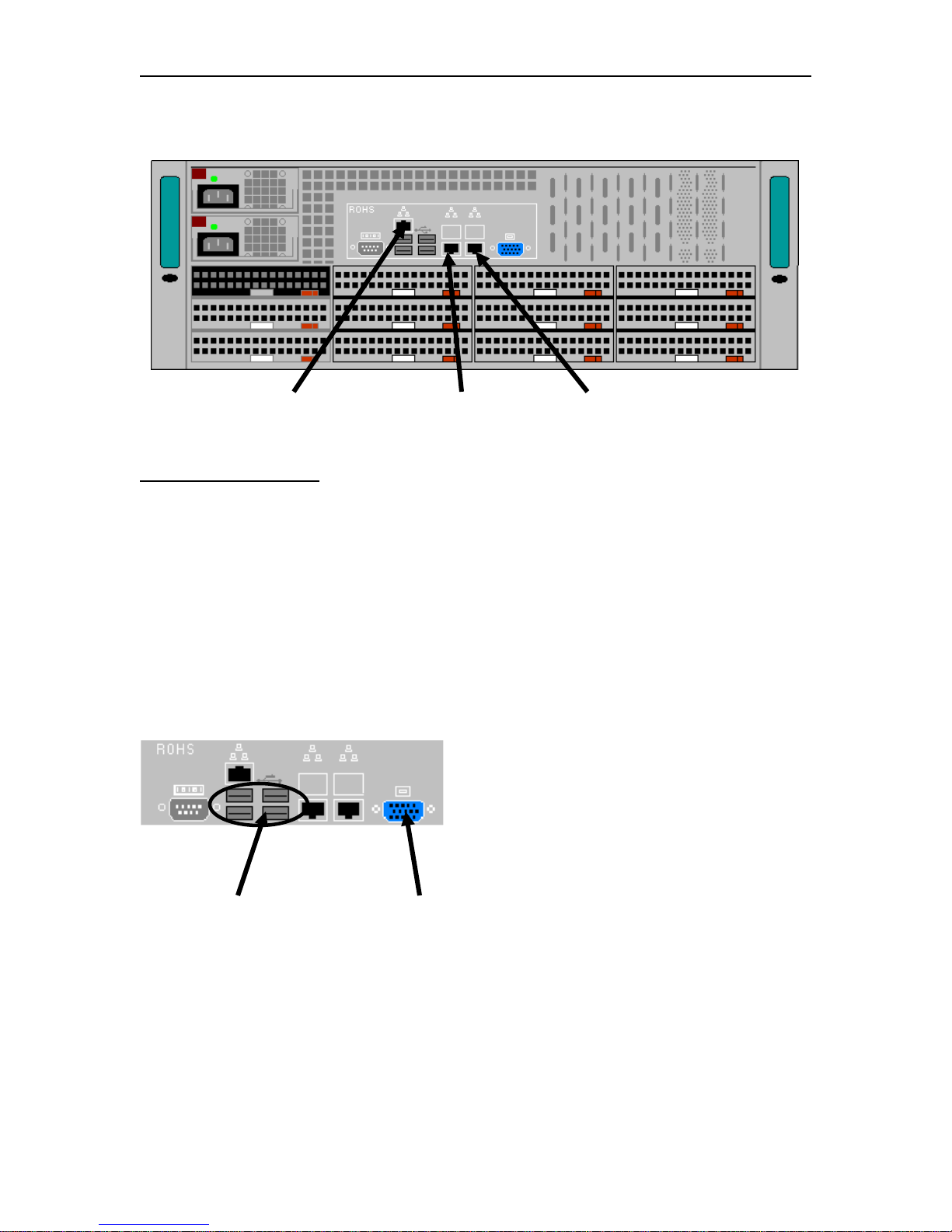
VI5990L Ethernet Connections
IPMI Console Attachment Ethernet 0 Ethernet 1
Local Console Control
You can attach a monitor, keyboard and mouse to the back of the VI-5990 as a console to
perform the initial configuration. The VI-5990 supports monitor, keyboard, and mouse
through USB sockets, or you can attach them through an IPMI interface. From the local
console, click on the [Start] button and select Programs>Firefox to bring up the local
browser for connecting to configuration.
VI-5990 Local Console Interface
USB Ports SVGA Interface
707166-001 1-11
 Loading...