

Page 1

1481A/G/W Display Station
Operator’s Manual
P/N 701408–002
Page 2
ELUDEHCSNOISIVER/EUSSI
stnemmoC.oN.veRetaD
esaeleRlaitinI100-80410739/10/50
esaeleRXTM200-80410789/92/50
IBM is a registered trademark of IBM Corporation
© Copyright 1998 by MTX Corporation
ii 701408–002
Page 3

This equipment complies with FCC regulations for EMI.
WARNING!
This equipment generates, uses, and can radiate radio
frequency energy, and, if not installed and used in accordance with the manual, may cause interference to radio
communications. It has been tested and found to comply
with the limits for a Class A computing device pursuant to
Subpart J of Part 15 of FCC Rules, which are designed to
provide reasonable protection against such interference
when operated in a commercial envir onment. Operation of
this equipment in a residential area is likely to cause interference, in whic h case users, at their o wn e xpense, will be
required to take whatever measures may be necessary to
correct the interference.
701408–002 iii
Page 4

iv 701408–002
Page 5
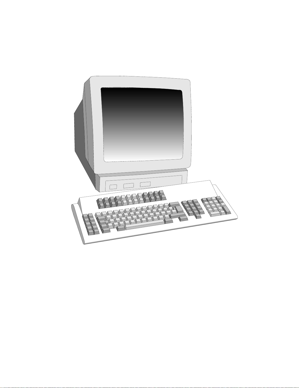
1481 Display Station
701408–002 v
Page 6

Table of Contents
Page
Chapter 1. Introduction ............................................................................................1-1
Standard Features............................................................................................1-2
Optional Features............................................................................................1-4
Chapter 2. Customer Installation .............................................................................2-1
Physical Statistics ...........................................................................................2-1
Environmental Requirements..........................................................................2-1
Inspecting the Packages ..................................................................................2-2
Unpacking Instructions ...................................................................................2-3
Packing Instructions........................................................................................2-3
Installing the Tilt/Rotate Stand .......................................................................2-4
Installing the Optional Light Pen ....................................................................2-4
Setting Up the Workstation.............................................................................2-5
Connecting the Display Station to the Host System .......................................2-6
Preliminary Operating T est .............................................................................2-6
Chapter 3. Setup Procedures ....................................................................................3-1
Keyboards .......................................................................................................3-1
Keyboard Operation Modes ............................................................................3-1
Emulation Mode .........................................................................................3-1
Native Mode ...............................................................................................3-2
Keyboard Def inition Mode.........................................................................3-2
Keyboard Controls..........................................................................................3-2
Entering Offline Setup Mode..........................................................................3-4
Offline Menu Screen ..................................................................................3-5
Offline Cursor Menu ..................................................................................3-6
Offline Keyboard Menu..............................................................................3-8
Offline Printer Menu ................................................................................3-11
Offline Miscellaneous Menu ....................................................................3-12
Online Setup Mode .......................................................................................3-14
Going Online ............................................................................................3-14
Entering Online Setup Mode ....................................................................3-14
Indicators ......................................................................................................3-19
Operator Status Row Indicators................................................................3-19
Readiness and System Connection Symbols ............................................3-20
“Do Not Enter” (Input Inhibited) Symbols...............................................3-21
Reminder Symbols ...................................................................................3-23
Shift and Mode Symbols ..........................................................................3-23
Coax Printer Status Symbols ....................................................................3-24
Local Printer Status Codes .......................................................................3-25
Local Error Indicators...............................................................................3-25
Entry Assist Indicators..............................................................................3-26
Response Time Monitor Indicators...........................................................3-26
Chapter 4. Operating Procedures .............................................................................4-1
Preparation for Operating ...............................................................................4-1
Assigning a Coax Printer ................................................................................4-2
Data Entry Function........................................................................................4-2
701408–002 vii
Page 7

Table of Contents
Keyboard Oper ations ......................................................................................4-4
Moving the Cursor......................................................................................4-4
Entering Data Characters and Selecting Modes .........................................4-5
Cursor Select Data Entry ............................................................................4-6
Data Editing Function.................................................................................4-7
Message Transmitting Function..................................................................4-8
Print Function .............................................................................................4-9
Extended Select Function ...........................................................................4-9
Using the Light Pen to Select Data ...............................................................4-11
Electronic Security Lock ..............................................................................4-11
Chapter 5. Entry Assist ............................................................................................5-1
Description......................................................................................................5-1
Entry Assist Functions ....................................................................................5-2
Entering Document Mode ..........................................................................5-2
Format Controls..........................................................................................5-2
Cursor Movement and Editing Functions ...................................................5-5
Chapter 6. Problem Determination and Maintenance ..............................................6-1
Page
Diagnostic T esting Function ...........................................................................6-1
Offline T ests ...............................................................................................6-1
System Manager Menu ...................................................................................6-1
Product ID.......................................................................................................6-5
Symptom/Action Chart ...................................................................................6-6
Preventiv e Maintenance ..................................................................................6-8
viii 701408–002
Page 8

List of Illustrations
Page
Figure 1-1. Screen Characteristics..............................................................1 -1
Figure 2-1. Display Station Packaging .......................................................2-3
Figure 2-2. Installing the Tilt/Rotate Stand ................................................2-4
Figure 2-3. 1481 Front V iew.......................................................................2-5
Figure 2-4. 1481 Receptacle Connectors....................................................2-6
Figure 2-5. Offline T est Menu ....................................................................2-7
Figure 3-1. Keyboard Key Functions..........................................................3-3
Figure 3-2. Offline Menu............................................................................3-4
Figure 3-3. Offline Screen Menu................................................................3-5
Figure 3-4. Offline Cursor Menu ................................................................3-6
Figure 3-5. Offline Keyboard Menu ...........................................................3-8
Figure 3-6. Offline Printer Menu ..............................................................3-11
Figure 3-7. Offline Miscellaneous Menu..................................................3-12
Figure 3-8. Online Rule Function.............................................................3-15
Figure 3-9. Online Auto Dim Time Function ...........................................3-16
Figure 3-10. Online MONOCASE/DualCase Function .............................3-17
Figure 3-11. Online Alarm V olume Function .............................................3-17
Figure 3-12. Online Click V olume Function...............................................3-18
Figure 3-13. Online Print/Printer T ype Function ........................................3-18
Figure 3-14. Online Mark Unprotected Fields Function.............................3-19
Figure 3-15. System Operator Status Row Fields.......................................3-20
Figure 4-1. T ypical Formatted Screen ........................................................4-3
Figure 4-2. Extended Select Function Overlay
(104-Key and 122-Ke y Keyboards)........................................4-10
Figure 4-3. Extended Select Function Overlay
(102-Key K eyboards).............................................................4-10
Figure 4-4. Extended Select Function Overlay
(88-Key K eyboards)...............................................................4-10
Figure 5-1. The Format Scale .....................................................................5-3
Figure 6-1. System Manager Menu ............................................................6-2
Figure 6-2. KBD Test .................................................................................6-2
Figure 6-3. Screen Alignment.....................................................................6-3
Figure 6-4. Enter Serial # Screen................................................................6-4
701408–002 ix
Page 9

Chapter 1. Introduction
This manual describes the 1481A/G/W Display Station, identifies controls and
operating procedures, and presents diagnostic and maintenance procedures that
can be performed by the operator. The manual also describes its data entry and
editing procedures.
The 1481 is an ergonomically designed data entry display station that offers a wide r ange
of functions and applications. It has a monochrome 14-inch monitor and can be ordered
in amber (A), green (G), or white (W).
eziSneercS
repsretcarahC
woR
neercSrepswoR
Figure 1-1. Screen Characteristics
As part of a system configuration, the 1481 can transmit and receive data from a
central processor unit (CPU) via the attaching controller. The operator enters or
changes information on a keyboard that resembles a typewriter. Entered data is
simultaneously displayed as alphanumeric characters and symbols on the display
screen. Function keys are used to transmit entered data to the CPU or to recall data
from the CPU to the display screen.
Hardware within the display station processes data during transmit and receive
operations. Attachment of a coax printer via the controller or an optional local screen
printer allows the operator to generate hard copy of all data displayed on the display
station screen.
Subsequent manual sections are:
0291
08
42
Customer Installation – Provides information on how to install the display station.
Setup Procedures – Describes the setup procedures and keyboard controls on the
display station.
Operating Procedures – Pro vides information required for entering and editing data at
the display station and for transmitting data messages.
Entry Assist – Describes access to and operation of the Entry Assist function.
Problem Determination and Maintenance – Describes av ailable maintenance plans,
system manager controls, and provides information required for diagnosing and
correcting display station-related problems.
701408-002 1-1
Page 10

Introduction
Standard Features
The 1481 is a customer-installable, ergonomically packaged, tabletop display station
capable of displaying up to 1920 characters on the screen. The display screen can be
formatted by a controller or host program for a variety of data entry applications. Data
can also be displayed as unformatted information. If it is interfaced with a coax printer
through a controller, or is attached to a local screen printer , it can provide a hard copy of
displayed information. Refer to Chapter 4, “Operating Procedures,” for more
information about formats and data entry procedures.
With the 88-key, 102-key, 104-key, and 122-key keyboards, the display station can
operate in E mulation mode or Nati ve mode. W ith the 102-key k eyboard, it can operate in
Native mode only . The operation mode is determined b y the Keyboard Type setting. (See
the “Offline Keyboard Men u” section in Chapter 3.)
The 1481 can be attached to any of the following control units or their plug- compatible
equivalents:
• T elex 076 Control Unit
• T elex 174 Control Unit
• T elex 274 Control Unit
• T elex 276 Control Unit/Display Station
• MTX/MTC 1174 Network Controller
• Memorex T ele x 1274 Control Unit
• Memorex T ele x 1374 Control Unit
• Memorex T ele x 2374 Control Unit
• Memorex 2274 Control Unit
• IBM 3174 Control Unit
• IBM 3276 Control Unit Display Station
• IBM 3274 Control Unit or plug-compatible equivalent
• IBM 4321 Processor by way of its Display Printer Adapter
• IBM 4331 Processor by way of its Display Printer Adapter
• IBM 4361 Processor by way of its Display Printer Adapter
The 1481 display station has the following standard features:
Tilt/Rotate Stand – Allo ws the display to be tilted o ver 20 deg rees of arc and rotated a
full 180 degrees for viewing ease.
1-2 701408-002
Page 11

Introduction
Offline Pull-Down Menus – The pull-do wn menus of fer simplicity and ease of use for
all setup functions.
Mono/Dual Case Mode – Allows the operator to specify all uppercase character entry
or upper- and lowercase character entry.
Mark Unprotected Field Indicator – The 1481 provides a menu option to acti vate the
Mark Unprotected Field indicator. When this option is activated, an underscore is
displayed in each unprotected field on the screen. This is particularly useful in entering
fields of data.
Auto Screen Cutoff – The screen automatically blanks when a specified amount of time
passes during which a keystroke is not entered. Hold do wn the Alt key while you press
the Shift key to restore the screen without adding characters. The amount of time before
cutoff can be specif ied in Setup mode as 2, 5, 10, 20, or 30 minutes. The feature can be
disabled for no cutoff.
Power Saver Function – When Auto Screen Cutoff is enabled and the “Status Row
Only” option is selected from the Dim Style function, only the status line is displayed on
the screen for the first 30 minutes. After 30 minutes, the entire screen, including the
status row, is blanked. Regardless of the dim style you choose (Status Row Only or
Monitor Off), the Power Saver function turns off the circuitry inside the terminal and
cuts power consumption by 50 percent.
Numeric Lock – Allo ws a field to be defined to accept only n umeric characters, and the
Period, Minus, and Dup keys. The comma can be substituted for the period on some
international keyboards.
Audible Alarm – Sounds when a character is entered in the next-to-last character
position of the screen (if the last character position is unprotected), or when the host
system signals the display station.
Local Screen Print – Allo ws you to make a hard copy of displayed text using the screen
print function. The feature can be used with any desktop/screen printer, which must be
ordered separately .
Host Print – Allo ws you to mak e a hard copy of displayed text using a coax printer via
the controller.
Response Time Monitor – Supports host-controlled transaction response time
monitoring.
Modifiable Keyboard – Using the Ke yboard Definition mode, the operator can modify
the keyboard layout by interchanging and adding keycaps. The control unit must be
properly configured to support this feature.
Entry Assist Function – Facilitates the creation and editing of text, such as memos,
letters, and documents. Refer to Chapter 5 for Entry Assist operation information. T he
attached controller must support this function.
701408-002 1-3
Page 12

Introduction
Serial Number Entry – This function allows you to verify or enter the display station
serial number. This information, along with Vital Product Data, is stored in the display
nonvolatile memory and is a v ailable to be read by the control unit for systems statistics
gathering by networks. The control unit to which you are attached must support this
function.
Optional Features
Keyboards – The 1481 offers a variety of keyboard types, each with a keyboard cable
that extends up to 72 inches (183 cm).
Light Pen – Allows the operator to select data from a display panel by pointing to it with
a pen-like device. This selection method provides a quick alternati ve to keying.
Security Keylock – Mechanical switch which allows the operator to secure and unlock
the terminal keyboard and display with a key.
1-4 701408-002
Page 13
Chapter 2. Customer Installation
This chapter lists the physical statistics and environmental requirements of the 1481
Display Station. It also describes the procedures for setting up the workstation and performing a preliminary operating test.
The display station is designed to be installed by the user. No special tools are required
to set up the display station.
Physical Statistics
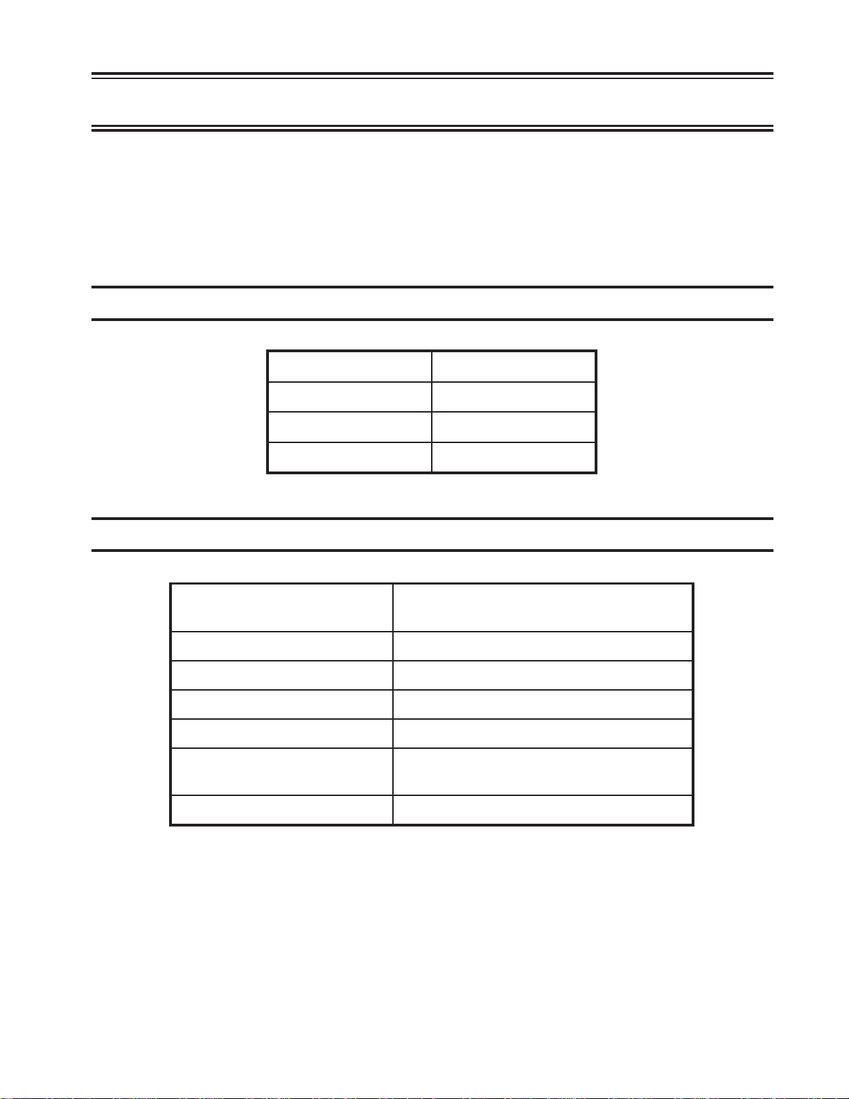
:thgieW)gk52.7(bl00.61
:thgieH)mc08.43(ni07.31
:htpeD)mc15.23(ni08.21
:htdiW)mc00.23(ni06.21
Environmental Requirements
:ecnaraelC
:egnaRerutarepmeTgnitarepO)C°6.04ot°01(F°501ot°05
:ytidimuHevitaleRnoitasnednocon,%08ot8
:bluBteWmumixaM)C°7.62(F°08
:rewoPzH36ot74taCAV462-081roCAV231-09
:noitpmusnoCrewoP
:noitapissiDtaeHegarevarh/UTB811
For units set at 100-120V: The power cable required for domestic units is a UL
listed, CSA certified, 18/3 AWG, type SVT or SJT cable (4.6 meters [15 feet maximum]). It is terminated on one end by a 125V, 15A grounding type attachment
connector. It is terminated at the other end by a 125V, 15A parallel blade grounding
type attachment plug.
nacegamaD.tinuehtfosedisllanosehcnixiS
.dekcolberastnevriafitluser
mumixamsttaw53–edoMlamroN
mumixamsttaw81–edoMneercSrewoP
701408-002 2-1
Page 14

Customer Installation
For units set at 200-240V: The power cable required for domestic units is a UL listed,
CSA certified, 18/3 AWG, type SVT or SJT cable (4.6 meters [15 feet maximum]). It is
terminated on one end by a 250V, 15A grounding type attachment connector. It is
terminated at the other end by a 250V, 15A tandem blade grounding type attachment
plug.
The power cable required for international units is an 18/3 AWG, type SJT cable (4.6
meters [15 feet maximum]). It is terminated on one end by a 250V, 15A grounding type
attachment plug body . It is terminated at the other end by a 250V, 15A grounding type
cord connector. The cord set is marked HAR to signify appropriate safety approv als.
The installation site must provide a properly wired and grounded power outlet. Do not
attach the display station to circuits that are connected to air conditioners or to devices
that generate significant transient electrical noise.
Electrostatic discharge in the vicinity of the unit should be minimized by avoiding
high-resistance floor material and carpeting that does not have antistatic properties, by
avoiding the use of plastic seats and cov ers, and by av oiding low humidity le vels. The
unit should be located away from areas that generate electromagnetic interference (for
example, transformers, power distribution panels, welding equipment, and motors).
The 1481 should not be installed where the atmosphere contains corrosive elements
that can damage the unit.
Do not run the cable in areas that produce electromagnetic interference (for example,
near transformers, switching equipment, welding equipment, power distribution
panels, and under carpets where vacuum cleaning is done). Also, heavy equipment should
not be moved or rolled over the ca ble.
Inspecting the Packages
Before you unpack the Display/Logic element and Keyboard element, inspect the carton
for physical damage.
If the exterior package is damaged, contact your local MTX sales office or distributor.
Also contact the carrier to request examination of the damage. The carrier is required to
complete and sign a damage report form.
Note: T o report damage, customers in the Continental U.S. should call MTX toll-free
at 1-888-648-7826 and ask for the Customer Service Department.
If the package is not damaged, remove the package contents as described on page 2-3.
2-2 701408-002
Page 15
Unpacking Instructions
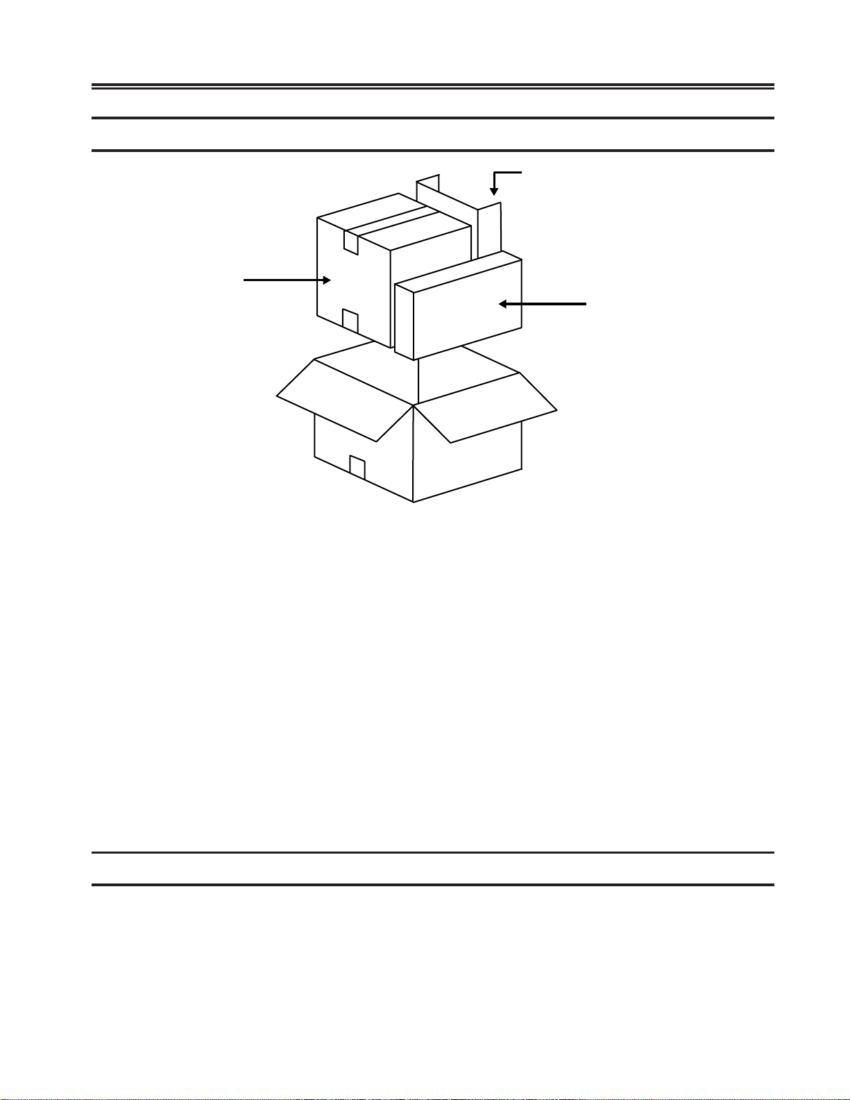
Display/Logic Element
with
Tilt/Rotate Stand
Customer Installation
Accessories
Keyboard Element
Figure 2-1. Display Station Packaging
1) Mo ve the car ton to the work area.
2) Open the carton from the top.
3) Remo ve the accessories carton. From the accessories carton, remove the operator’ s
manual, power cord, and, if ordered, the light pen. Place these items con veniently
aside.
4) Remove the carton containing the Keyboard element. Remove the keyboard and
place it aside.
5) Remove the carton containing the Display/Logic element. Open the carton and
remove the T ilt/Rotate stand and the Display/Logic element. Remov e the two side
cushions. Place the Display/Logic element on a sturdy, flat surface. See “Installing
the Tilt/Rotate Stand” on Page 2-4 for instructions on ho w to install the T ilt/Rotate
stand.
Packing Instructions
1) To pack the Display/Log ic element for shipment, repack the element in its
appropriate box. Use reinforced nylon tape to close the box.
2) T o pack the Keyboar d element for shipment, repack the element in its appropriate
box. Use reinforced nylon tape to close the box.
701408-002 2-3
Page 16
Customer Installation
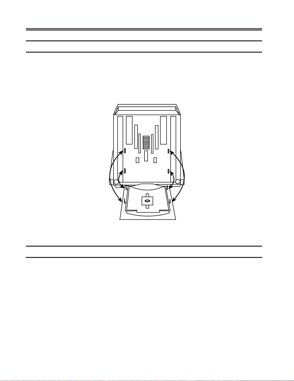
Installing the Tilt/Rotate Stand
1) Turn the Display/Logic element face down with the bottom facing to ward you.
2) Insert the four tabs on the Tilt/Rotate stand into the slots on the bottom of the
Display/Logic element and slide the T ilt/Rota te stand up until it locks into place
in the slots (see Figure 2-2).
3) Turn the display element with the installed T ilt/Rotate stand upright.
Figure 2-2. Installing the T ilt/Rotate Stand
Installing the Optional Light Pen
Use this procedure to install the optional light pen:
1) Remove the light pen and its holder from the protective wrap.
2) Insert the light pen’s cable connector into its 4-pin receptacle on the rear of the
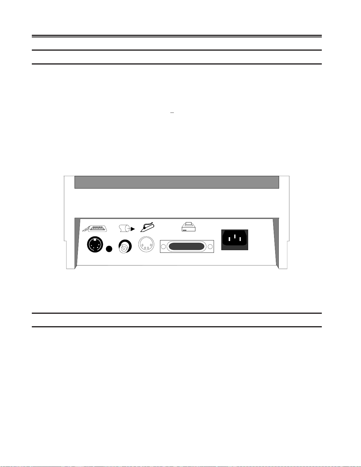
display cabinet. Check to ensure that the connector is firmly seated. Figure 2-4 shows
the location of the light pen cable connector’ s receptacle.
3) Peel the protective cover from the light pen holder’s mounting surface.
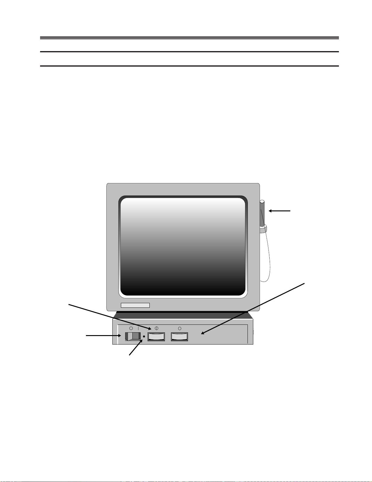
4) Mount the light pen holder onto the side of your display station as displayed in
Figure 2-3.
5) Measure the amount of cord needed for the light pen to reach from the holder to any
point on the screen. Leaving this amount free, place the light pen cord into the cord
retainers.
2-4 701408-002
Page 17
Setting Up the Workstation
1) Place the Display/Logic element within connecting distance of an appropriate AC
power outlet.
2) Place the keyboard in front of the Display/Logic element. Pull out the feet
underneath the keyboard to adjust it to a higher setting, if desired. Insert the
keyboard plug into the receptacle on the back of the Display/Logic element. See
Figure 2-4 for the keyboard plug receptacle location.
3) Attach the printer cable (provided with your printer) to the connector on the back of
the Display/Logic element as displayed in Figure 2-4.
4) Make sure that the Power-On/Off switch is set to Of f (see Figure 2-3).
5) Plug the power cord into the power receptacle on the back of the Display/Logic element
(see Figure 2-4).
Customer Installation
Contrast Control
Power–On/Off
Switch
Light Pen
Brightness Control
Power–On
Indicator
Figure 2-3. 1481 Front V iew
701408-002 2-5
Page 18
Customer Installation
Connecting the Display Station to the Host System
Connect the display station to the host or to a controller with a coax cable up to 1500
meters (4920 feet) long, or a twisted-pair cable with a minimum length of 30.5 meters
(100 feet) and a maximum length of 277 meters (900 feet). Coax cable and twisted-pair
cables can be combined. This formula shows lengths:
(coax length) + (5 x twisted-pair length)
Follow these steps to connect the display station to the host system or to a controller:
1) Locate the coax or twisted-pair cable extending from the controller.
2) Align the end of the connector cable with the Dual Purpose connector on the back of
the Display/Logic element (see Figure 2-4). Connect the cable and secure it in place
by turning the retaining ring clockwise until it is tight.
< 1370 meters (4500 feet)
Figure 2-4. 1481 Receptacle Connectors
Preliminary Operating Test
1) Ensure that the system control unit is powered on and operational.
2) Set the Power-On/Off switch to On ( | ) while simultaneously holding do wn any key
except the Reset key. After a few seconds, an alarm sounds.
3) Hold the key down until a screen resembling the one in Figure 2-5 appears. If the
screen remains blank, the Contrast and Brightness controls may need adjusting.
2-6 701408-002
Page 19
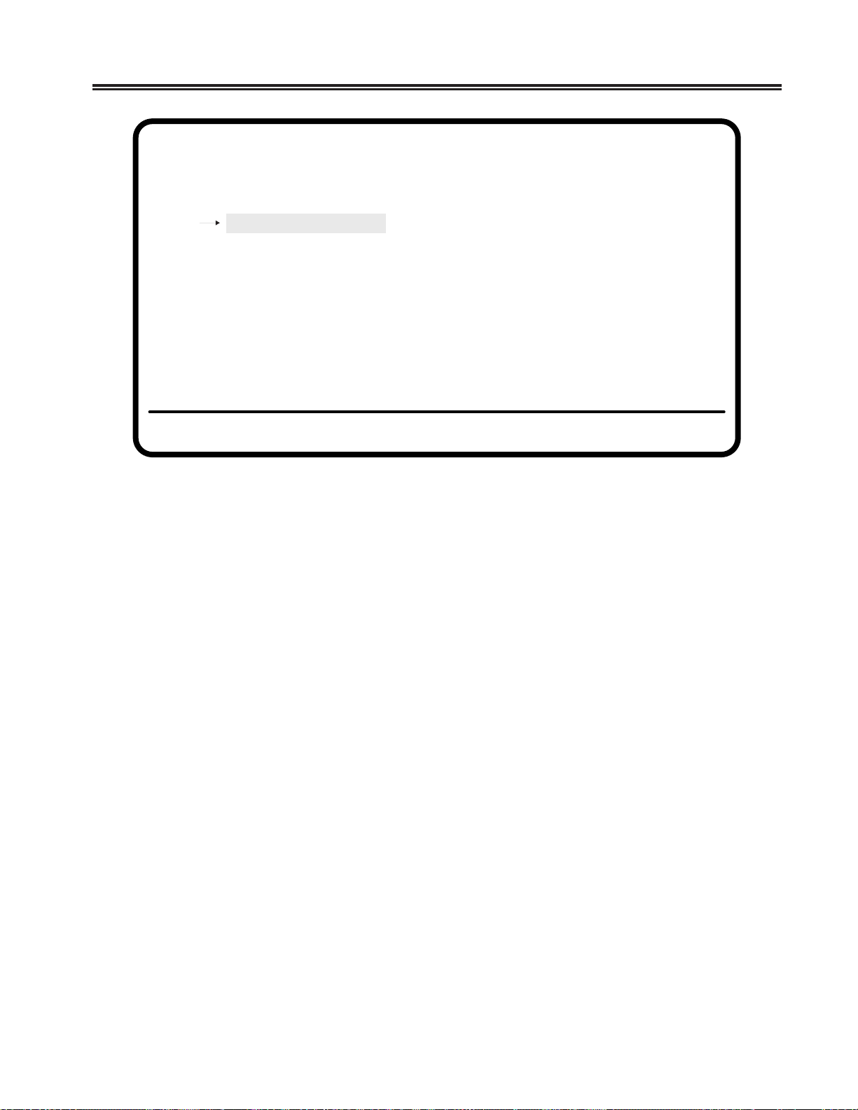
Select One of the Following
User Menu
System Manager Menu
Product ID
Go Online
Customer Installation
Offline Test Menu
Figure 2-5. Offline Test Menu
4) Obtain the proper settings for your display station from your system operator. The
controller to which the unit attaches must be configured to support the settings
selected. T o adjust the display station’ s controls or change the settings for screen,
cursor, keyboar d, printer , or other attrib utes, see Chapter 3, “Setup Procedures.”
If the display station is set correctly, it is ready to go online. Use the Up and Do wn
arrow keys to highlight Go Online on the Of fline T est menu and press the Enter ke y.
The displays station goes online.
If the display station is not connected to a controller, the cursor is displayed in the
upper left corner of the screen and the operator status row is displayed a t the bottom.
If the display station is connected to a controller, the type of controller determines
the appearance of the online screen.
5) If the cursor and operator status row are not displayed, adjust the Contrast and/or
Brightness controls. If adjusting the Contrast and/or Brightness controls does
not display the cursor and operator status row, refer to Chapter 6, “Problem
Determination and Maintenance. ”
6) Installation of the display station is now complete.
701408-002 2-7
Page 20

The following sections describe the setup procedures for the 1481 Display Station and
its attached keyboard. Both offline and online setup functions are described.
Keyboar ds
Optional Keyboards:
• 88-Key T ype writer/PF1-12 Pad
• 88-Key T ypewriter/PF13-24 Pad
• 88-Key T ype writer/Tripad
• 88-Key T ypewriter/Numeric Pad
• 102-Key T ypewriter
• 102-Key PC T ypew riter
• 104-Key T ypewriter
Chapter 3. Setup Procedures
• 104-Key Data Entry
• 122-Key T ypewriter
• 122-Key Data Entry
• International Keyboards
Keyboard Operation Modes
You can select either of two keyboard operation modes, Emulation or Native. The
default setting is to emulate an IBM 3278 88-key keyboard. You can change the
keyboard operation mode by changing the Keyboard Type under the Offline Keyboard
menu. See “Offline Keyboard Menu” in this chapter for information on how to select
keyboard operation modes.
Keyboard Definition mode is supported with Na tive Mode selections.
Emulation Mode
Emulation mode is available for a 122-key, a 104-key , or an 88-key keyboard. In this
mode, the keyboard emulates an IBM 3278 88-key keyboar d and the Typewriter
Numeric Pad operates only in Nonshift mode. Some keys on the 122-key keyboard
do not function in Emulation mode. The control unit to which the display station is
attached must be configured to support Emulation mode.
701408-001 3-1
Page 21

Setup Procedures
Native Mode
Native mode is av ailable on the 88-key , 102-key, 104-key, and 122-key keyboards. All
122-key keyboard functions and the Ke yboard Def inition mode ar e available in Native
mode. To use Native mode, you must be connected to one of the following controllers:
• MTX/MTC 1174 Network Controller
• Memorex Telex 1274 Control Unit at firmware release level 11.0 or higher
• IBM 3174 Control Unit
• IBM 3274 Control Unit at configuration support D microcode release level 63.0 or
higher
To use Native mode with a 102-key keyboard, you must be connected to one of the
following controllers:
• MTX/MTC 1174 Network Controller
• Memorex Telex 1274 Control Unit at firmware release 16.0 or higher (if the 1274
supports Multiple Logic Sessions, firmware release 53.0 or higher)
• IBM 3174 Control Unit
The control unit to which the display station is attached must be configured to support
Native mode.
Keyboard Definition Mode
In Native mode, the 1481 supports Keyboard Def inition mode. W ith Ke yboard De fi nition mode, you can modify the keyboard layout by using the control unit’ s Keyboard
Definition Utility . The attached control unit must be configured to support this feature.
Keyboard Controls
This section describes keys on the 88-key , 102-key , 104-ke y , and 122-key keyboards that
control display station functions.
Alt – Simultaneously press the Alt ke y and any other ke y to activate functions specif ied
on the front key face. Only keys with labeled front f aces hav e Alt (alternate) functions.
Shift – Press and hold the Shift key and press any key with a shifted function on the
keytop to activ ate that shift function.
3-2 701408-002
Page 22
Setup Procedures
Reset – Press the Reset key to restore keyboard operations after an error condition, to
end character insertion in Insert mode, or to terminate a printer identification sequence
before all characters have been entered .
Change Screen – Press the Change Screen key to toggle between sessions. The Change
Screen key does not work with all controllers. The Change Screen key may not function
on the 88-key keyboard.
PA3 – The PA3 key is an additional function key. It does not w ork with all controllers. T o
use the PA3 key on the 88-key keyboard, hold down both the Alt and Shift keys while
you press the PA3 key.
Shift Function
Nonshift Function
Alt Function
Key Face
Key Top
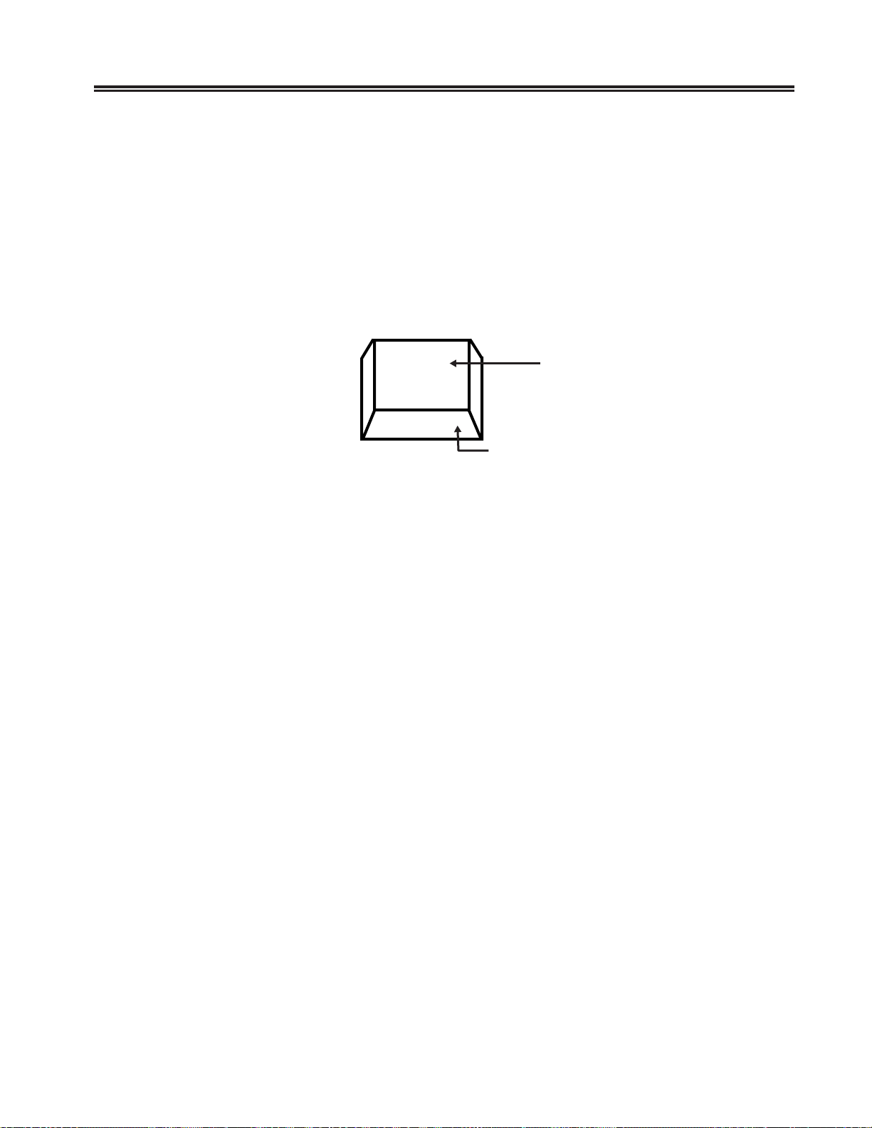
Figure 3-1. Keyboard K ey Functions
Each keyboard type contains autorepeat keys that repeat their functions as long as they
are pressed. The autorepeat keys include all keys that enter alphabetic, numeric, or
symbol characters, the space bar, all keys that assign or mov e the cursor position, and
the following special-purpose Data Entry keyboard k eys:
• Field Mark
• Duplicate
• Skip
The following keys are not supported by the 1481:
• Recrd
• Play
• Back
• Fwd
• Pause
701408-002 3-3
Page 23

Setup Procedures
Entering Offline Setup Mode
Most screen, cursor, keyboard, and printer options, as well as several miscellaneous
attributes, are selected or changed with offline user menus.
T o enter Offline Setup mode, hold down any key while you turn the display station on.
The Offline Test menu is displayed (Figure 2-5 on Page 2-7).
To enter setup mode when the display station is online, press and hold down at the
same time the Alt ke y, the Caps Lock key, and the Test key. The Offline Test menu is
displayed (Figure 2-5 on Page 2-7).
Use the Up and Down Arrow keys to highlight User Menu on the Of fline T est menu and
press Enter . The Of fline menu is displayed (Figure 3-2).
Offline Menu Screen
Screen Cursor Keyboard Printer Miscellaneous
Use Arrow Keys to choose item
Use ENTER Key to change item
RESET Key Exits
Figure 3-2. Offline Menu
3-4 701408-002
Page 24

Offline Menu Screen
T o display the options on the Offline Screen menu, use the Left and Right Arr ow keys to
highlight Screen on the Offline menu and press the Enter key . The Offline Screen menu
is displayed (Figure 3-3).
Screen Cursor Keyboard Printer Miscellaneous
MONOCASE/DualCase DualCase
Mark Unprotected
Reverse Video
Setup Procedures
Offline Menu Screen
Yes
Off
Use Arrow Keys to choose item
Use ENTER Key to change item
RESET Key Exits
Figure 3-3. Offline Screen Menu
MONOCASE/DualCase
To choose the monocase or dualcase option, use the Up and Down Arrow keys to
highlight MONOCASE/DualCase and press the Enter key to toggle between
MONOCASE and DualCase. Select MONOCASE if you want all letters on the screen
to appear in uppercase. Select DualCase if you want characters to appear in both
upper- and lowercase.
You can also select monocase or dualcase with the Online MONOCASE/DualCase
Function. See “MONOCASE/DualCase Function” on Page 3-17.
Mark Unprotected
Use the Up and Down Arrow ke ys to highlight Mark Unprotected . Press the Enter key
to toggle between On and Off. When Mark Unprotected is turned on, an underline ( _ )
is displayed in each unprotected field on the screen. When Mark Unprotected is turned
off, no unprotected field indicator is displayed.
701408-002 3-5
Page 25

Setup Procedures
Y ou can also turn Mark Unprotected on and off with the Online Mark Unprotected Fields
function. See “Mark Unprotected Fields Function” on Page 3-19.
Reverse Video
The Reverse Video option can only be set on the 1481W. Use the Up and Down Arrow
keys to highlight Reverse V ideo and press the Enter key to toggle between On and Off.
Set Reverse Video on to display black characters on a white background. Set Reverse
Video of f to display white characters on a black background.
Leaving the Offline Screen Menu
T o leave the Of fline Screen menu, use the Left and Right Arro w keys to display another
offline setup menu or press the Reset key to exit from Off line Setup mode and return to
the Offline Test menu.
Offline Cursor Menu
T o display the options on the Offline Cursor menu, use the Left and Right Arrow ke ys to
highlight Cursor on the Offline menu and press the Enter key . The Of fline Cursor menu
is displayed (Figure 3-4).
Offline Menu Screen
Screen Cursor Keyboard Printer Miscellaneous
Cursor Size Block
Cursor Blink
Rule Style
Use Arrow Keys to choose item
Use ENTER Key to change item
RESET Key Exits
On
+
Figure 3-4. Offline Cursor Menu
3-6 701408-002
Page 26

Setup Procedures
Cursor Size
Use the Up and Down Arrow keys to highlight Cursor Size and press the Enter key to
toggle between Block and Underline. Use this option to choose either a block (
cursor or an underline ( _ ) cursor.
Cursor Blink
Use the Up and Down Arrow ke ys to highlight Cursor Blink and press the Enter key to
toggle between On and Off. Select On if you want a blinking cursor or Off if you want
a nonblinking cursor .
Rule Style
To chose a rule cursor style of either dash (-), bar ( | ), or cross (+), use the Up and
Down Arro w keys to highlight Rule Style and press the Enter key to toggle between
+, |, and -.
Y ou can also choose a rule cursor style with the Online Rule Cursor function. See “Rule
Cursor Function” on Page 3-15.
)
Press the Rule key (on the 88-key and 102-key ke yboards, hold do wn the Alt key while
you press the Rule key) to turn the rule cursor on or off.
Leaving the Offline Cursor Menu
T o leav e the Offline Cursor menu, use the Left and Right Arro w keys to display another
offline setup menu or press the Reset key to exit from Of fline Setup mode and return to
the Offline Test menu (Figure 2-5 on Page 2-7).
To save the options you set on the Offline Cursor menu, after you leave Offline Setup
mode, you must highlight Go Online on the Offline Test menu and press the Enter key.
701408-002 3-7
Page 27

Setup Procedures
Offline Keyboard Menu
To display the options on the Offline Keyboard menu, use the Left and Right Arrow
keys to highlight Keyboard on the Of fline menu and press the Enter ke y . The Of fline
Keyboard menu is displayed (Figure 3-5).
Screen Cursor Keyboard Printer Miscellaneous
Alarm V olume Off
Click Enable
Click V olume
Cursor Speed 10 CPS
Repeat Delay
Keyboard T ype
Change KEYLESS Password
Offline Menu Screen
On
Off
Short
TW
OffNumeric Lock
Use Arrow Keys to choose item
Use ENTER Key to change item
RESET Key Exits
Figure 3-5. Offline K eyboard Menu
Alarm Volume
To turn the alarm volume off and on, use the Up and Down Arrow keys to highlight
Alarm V olume and press the Enter key to toggle between Off and 1, 2, 3, 4, 5, 6, and 7.
Turn the alarm of f by selecting Off, or select an alarm volume from 1 (lowest) through 7
(highest).
Y ou can also set the alarm v olume with the Online Alarm Volume Function. See “ Alarm
Volume Function” on Page 3-17.
Click Enable
Use the Up and Down Arro w ke ys to highlight Click Enable and press the Enter key to
toggle between On and Off. Select On to make the keyboard click with each keystroke
or select Off to deactivate the ke yboard click.
If an “Input inhibited” error occurs while Click Enable is activated, the keyboard click is
turned off. If an error occurs while the feature is deactivated, the ke yboard click is turned
on.
3-8 701408-002
Page 28

Setup Procedures
Click Volume
Use the Up and Down Arrow k eys to highlight Click V olume and press the Enter key to
toggle between Off, 1, 2, 3, 4, 5, 6, and 7. Turn the keyboar d click off by selecting Off, or
select a click volume from 1 (lowest) through 7 (highest).
You can also adjust the keyboard click volume with the Online Click Volume function.
See “Click Volume Function” on Page 3-18.
Cursor Speed
Use the Up and Down Arrow keys to highlight Cursor Speed and press the Enter key to
toggle between horizontal cursor speeds of 10 CPS, 20 CPS, and 30 CPS.
Repeat Delay
Press the Up and Down Arrow ke ys to highlight Repeat Delay and press the Enter key to
toggle between typeamatic speeds for autorepeat keys of Short, Medium, and Long .
Keyboar d Type
Note: Check with your system operator before you change this value.
Use the Up and Down Arro w keys to highlight K eyboard Type and press the Enter key
to toggle between the following ke yboard settings:
• TW (native type writer)
• DE (data entry) – not available with 102-key k eyboard
• 01 (user defined)
• 02 (user defined)
• 03 (user defined)
• 04 (user defined)
• 88 (Emulate 88-key keyboard) – not av ailable with 102-key k eyboard
Numeric Lock
Note: Check with your system operator before turning the numeric lock off or on.
Use the Up and Down Arrow ke ys to highlight Numeric Lock and press the Enter key to
toggle between numeric lock On and Off.
701408-002 3-9
Page 29

Setup Procedures
Change KEYLESS Password
The user-definable password for Electronic Security Lock mode can be modified by
performing the following steps:
1) Move the pointer (with the Up or Down Arrow keys) to the Change KEYLESS
Password prompt and pr ess Enter .
2) The user is then prompted to input the current password. (As each keystroke is
input, the leftmost underscore is changed to an “X”). If an incorrect password is
input, “FAIL” is added, and the Change prompt and the password prompt are
removed. To retry, the user must press Enter to restore the prompt.
Note: The default password as shipped or after RESET NVRAM is “OPR”.
3) If the password is correctly entered, the user is then prompted for a new password.
The next three keystr okes are taken as the ne w password.
4) The user is then prompted to reenter the new password to verify the chang e. When
the third keystroke is entered, all of the password prompts are removed. If the
keystrokes do not match, “FAIL” is added to the Change prompt.
Leaving the Offline Keyboard Menu
To leave the Offline Keyboard menu, use the Left and Right Arrow keys to display
another offline setup menu or press the Reset ke y to exit from Offline Setup mode and
return to the Offline Test menu.
T o save the options you set on the Of fline Keyboard menu, after you leav e Offline Setup
mode you must highlight Go Online on the Offline Test menu and press the Enter key .
3-10 701408-002
Page 30

Offline Printer Menu
T o display the options on the Offline Printer menu, use the Left and Right Arrow ke ys to
highlight Printer on the Offline menu and press the Enter key . The Offline Printer menu
is displayed (Figure 3-6).
Screen Cursor Keyboard Printer Miscellaneous
Printer Type 1201
Print Type
Auto Skip
Use Arrow Keys to choose item
Use ENTER Key to change item
RESET Key Exits
Setup Procedures
Offline Menu Screen
Screen Print
Off
Figure 3-6. Offline Printer Menu
Printer T ype
Use the Up and Down Arro w keys to highlight Printer T ype and press the Enter key to
toggle between an 1173 and a 1201 local screen printer.
You can also select the printer type with the Online Print/Printer Type function. See
“Print/Printer T ype Function” on Page 3-18.
Note: Use of an y local screen printer other than the 1173 or the 1201 for local screen
print could produce unpredictable results and is neither recommended nor
supported.
Print T ype
Use the Up and Down Arrow keys to highlight Print Type and press the Enter key to
toggle between the following types of printing jobs:
• System Print – The display station contents are printed on the printer attached to the
control unit.
• Screen Print – The display station contents are printed on the local printer attached
to the display station.
701408-002 3-11
Page 31

Setup Procedures
Auto Skip
You can configure your display station’s local printer to advance a selected number of
lines after it performs a local print. T o set up or change the lines to be adv anced, use the
Up and Down Arrow k eys to highlight A uto Skip, then follo w these steps:
1) Press Enter. The selection area for the Auto Skip function is highlighted.
2) Use arrow keys to select a new value. Allowable values are Off, 1–14, and Form
Feed. The number you select is the number of lines you want the local printer to
advance after performing a local print operation.
Leaving the Offline Printer Menu
T o leave the Of fline Printer menu, use the Left and Right Arrow k eys to display another
offline setup menu or press the Reset key to exit from Off line Setup mode and return to
the Offline T est menu (Figure 2-5 on P age 2-7).
To save the options you set on the Offline Printer menu, after you leave Offline Setup
mode, you must highlight Go Online on the Offline Test menu and press the Enter key.
Offline Miscellaneous Menu
To display the options on the Offline Miscellaneous menu, use the Left and Right
Arrow keys to highlight Miscellaneous on the Offline men u and press the Enter key . The
Offline Miscellaneous menu is displayed (Figure 3-7).
Screen Cursor Keyboard Printer Miscellaneous
Setup Language English
Dim Timer
Dim Style
Coax Indicator
VPD
Use Arrow Keys to choose item
Use ENTER Key to change item
RESET Key Exits
Offline Menu Screen
10 minutes
Status Row Only
On
Off
Figure 3-7. Offline Miscellaneous Menu
3-12 701408-002
Page 32

Setup Procedures
Setup Language
Choose between English, German, French, and a set of International symbols to
display in the pull-down menus. Use the Up and Down Arrow keys to highlight
Setup Language. Press Enter to toggle between English, German, and French.
Dim Timer
Use this option to turn the Auto Screen Cutoff function on or off by using the Up and
Down Arrow k eys to highlight Dim Timer. Press Enter to toggle between Off, 2, 5, 10,
20, and 30 minutes. The Auto Screen Cutoff functions blanks the screen if no data is
received from the keyboard or a host system for the amount of time specified in the
online Auto Dim Time setup option. See “Auto Dim Time Function” on Page 3-16 for
instructions on how to select the auto dim time.
Dim Style
You must turn the Auto Screen Cutof f function on with the Dim T imer function (above )
in order to use the dim style you choose with this function.
Use the Up and Down Arrow keys to highlight Dim Style and press the Enter key to
toggle to Monitor Off. The Monitor Off selection blanks the entire screen. Press
Enter again to toggle to Status Row Only. The Status Row Only option displays only
the operator status row when the screen is blanked. The symbol
operator status row . Press an y key to restore the screen without adding characters. Also,
if the host initiates a write message, the screen is restored.
appears on the
If you select Status Row Only, the screen remains blanked with only the status row
displayed for 30 minutes. After 30 minutes, the status ro w is also blanked (po wer down
mode).
To restore a blanked screen, press the Shift key. The screen is also restored when the
control unit writes to the screen.
Coax Indicator
When this feature is turned on, a filled circle ( ) is displayed in column 69 of the status
row to indicate an active coax line w hile online. A blinking circle indicates a very slow
poll cycle indicative of a coax line being disconnected then reconnected. If your display
station displays a blinking circle, power down the display station for at least 10 seconds
before turning the power on to reestablish communication.
To turn the Coax indicator on or off, highlight Coax Indicator on the Miscellaneous
menu and press the Enter key to toggle the indicator On or Off.
VPD
Use the Up and Down A rro w keys to highlight VPD (Vital Product Data) and press the
Enter key to toggle between On and Off. T urn the VPD option On to send VPD such as
the serial number, the M/C type, the EC number, the manufacturing plant, and the
softwar e le v el t o t he controller .
701408-002 3-13
Page 33

Setup Procedures
Leaving the Offline Miscellaneous Menu
T o lea ve the Of fline Miscellaneous menu, use the Left and Right Arrow keys to display
another offline setup menu or press the Reset key to exit from Offline Setup mode and
return to the Offline Test menu (Figure 2-5 on Page 2-7).
T o sa v e the options you set on the Of fline Miscellaneous menu, after you lea ve Of fline
Setup mode you must highlight Go Online on the Offline T est menu and press the Enter
key .
Online Setup Mode
Some screen, cursor, keyboard, and printer options can be selected or changed in online
setup mode. They can also be changed or selected in Of fline Setup mode. See “Entering
Offline Setup Mode” on Page 3-4 for instructions on how to change these options in
Offline Setup mode.
In Offline Setup mode, the coax indicator is a filled triangle (
Going Online
T o go online when you po wer up, turn the Powe r-On/Off switch to On ( | ).
T o go online from the Offline T est menu (Figure 2-5 on P age 2-7), use the Up and Down
Arrow keys to highlight Go Online and press the Enter key.
Entering Online Setup Mode
To enter Online Setup mode, your display station must first be online. Follow the
instruction in “Going Online,” above, to put your display sta tion online.
To enter Online Setup mode from a 104-, 122-, or 88-key keyboard, hold down the Alt
key while you press the Setup key. The online Rule Cursor function is displayed in the
last 10 characters on the operator status row .
To enter Online Setup mode from a 102-key keyboard, hold down the Shift key while
you press the Setup key. The online Rule Cursor Function is displayed in the last 10
characters on the operator status row.
Use the Up and Down Arrow ke ys to toggle through the following online setup functions:
).
• Rule Cursor
• Auto Dim Time
• MONOCASE/DualCase
• Alarm V olume
3-14 701408-002
Page 34
Setup Procedures
• Click V olume
• Print/Printer T ype
• Mark Unprotected Fields
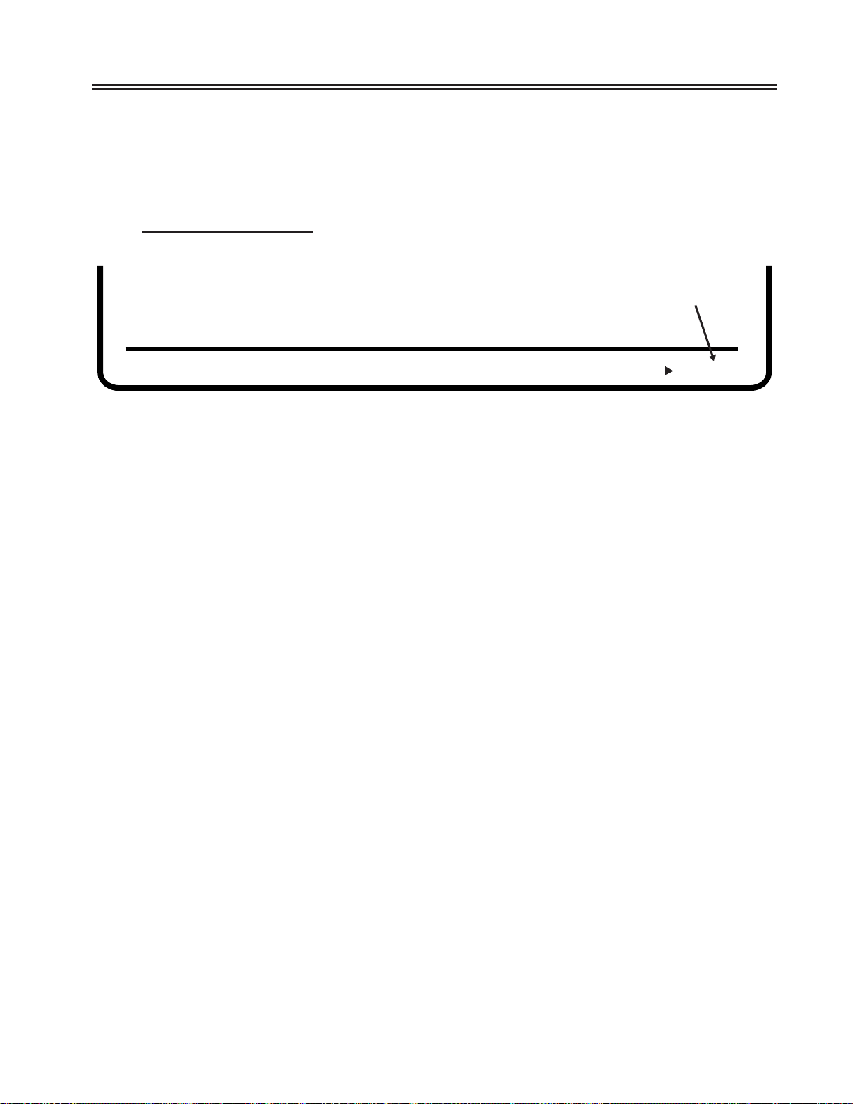
Rule Cursor Function
Rule Cursor Character
Figure 3-8. Online Rule Function
The rule cursor character is displayed inside the parentheses at the end of the Rule
Cursor function. Use the Enter key to scroll through the following choices for the rule
cursor character:
– + – (+)
• | (vertical bar)
• - (dash)
• + (cross)
When the rule cursor character you want is displayed in the parentheses, press the Up
and Down Arrow keys to scroll forwa rd or backward to the next online setup function or
hold down the Alt key while you press the Setup key (for the 102-key keyboard, hold
down the Shift key while you press the Setup ke y) to exit from Online Setup mode.
Press the Rule key (on the 88-key and 102-key ke yboards, hold do wn the Alt key while
you press the Rule key) to turn the rule cursor on or off.
701408-002 3-15
Page 35
Setup Procedures
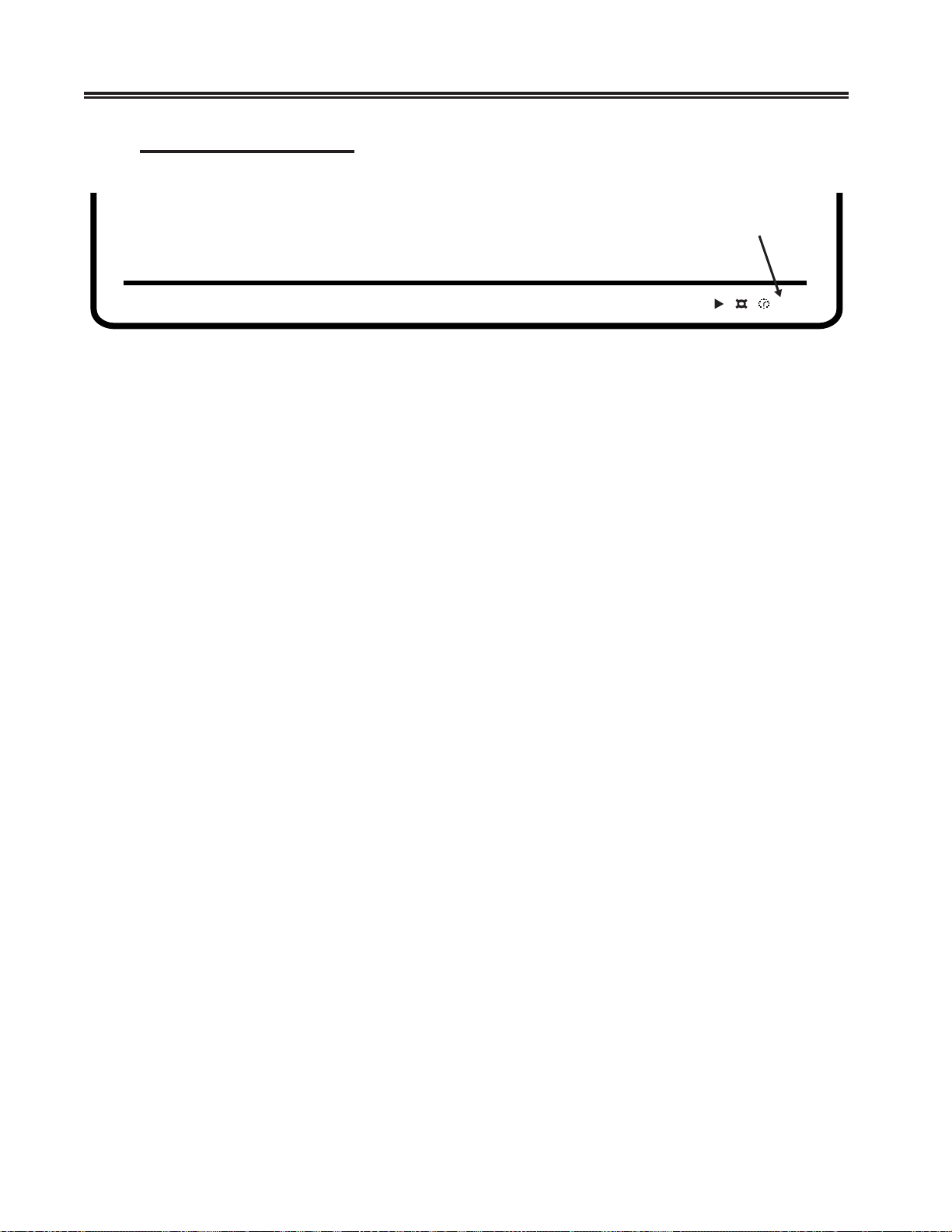
Auto Dim Time Function
The auto dim time is the time the display station waits for input before blanking the
screen. The number of minutes to wait for auto dim is displayed in the last two fields of
the Auto Dim T ime function. Use the Enter ke y to scroll through the following choices:
• 0 (auto dim off)
• 2 (minutes)
Auto Dim Time
(in minutes)
nn
Figure 3-9. Online Auto Dim Time Function
• 5 (minutes)
• 10 (minutes)
• 20 (minutes)
• 30 (minutes)
When the auto dim time you want is displayed, press the Up and Down Arrow keys to
scroll forward or backward to the next online setup function or hold down the Alt key
while you press the Setup key (for the 102-key keyboard, hold do wn the Shift key while
you press the Setup key) to exit from Online Setup mode.
To restore a blanked screen, press the Shift key. The screen is also restored when the
control unit writes to the screen.
3-16 701408-002
Page 36
Setup Procedures
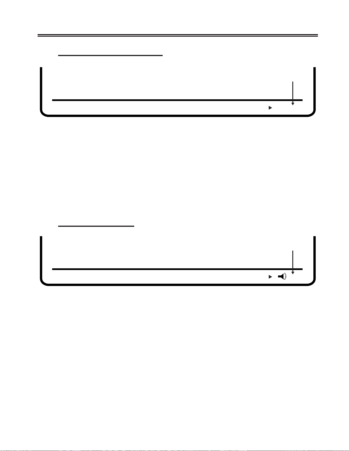
MONOCASE/DualCase Function
DualCase Selection
Figure 3-10. Online MONOCASE/DualCase Function
Use the Enter key to select all uppercase characters on the screen (MONOCASE) or
both upper- and lowercase characters (DualCase). T o select MONOCASE, display A,A
in the last two fields of the MONOCASE/DualCase Function. To select DualCase,
display A,a in the last two f ields.
When the character mode you want is displayed, press the Up and Down Arro w keys to
scroll forward or backward to the next online setup function or hold down the Alt key
while you press the Setup key (for the 102-key keyboard, hold do wn the Shift key while
you press the Setup key) to e xit from Online Setup mode.
A,a
Alarm V olume Function
Figure 3-11. Online Alarm Volume Function
Use the Enter key to select an alarm volume of 0 (off) through 7 (loudest). The alarm
volume is displayed in the last field of the Alarm Volume function.
When the alarm volume you want is displayed, press the Up and Down Arrow keys to
scroll forward or backward to the next online setup function or hold down the Alt key
while you press the Setup key (for the 102-key keyboard, hold do wn the Shift key while
you press the Setup key) to e xit from Online Setup mode.
Alarm V olume
n
701408-002 3-17
Page 37
Setup Procedures
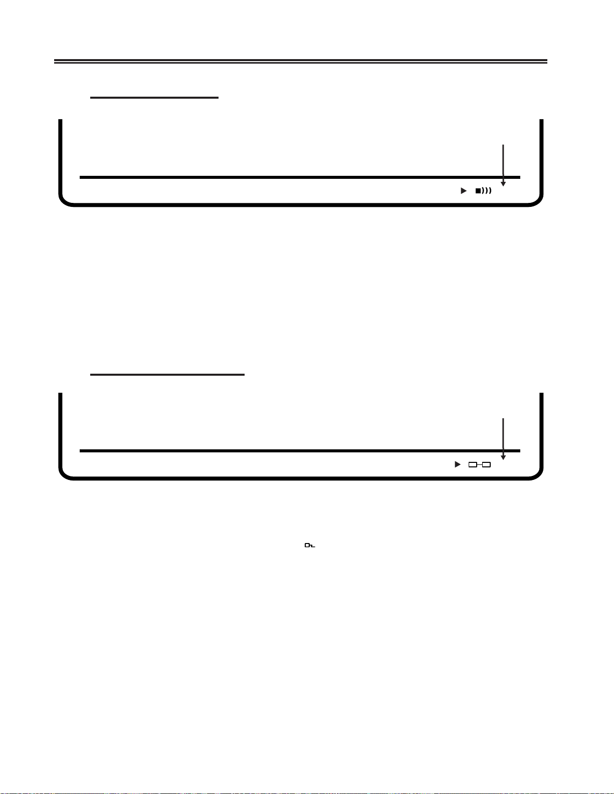
Click V olume Function
Use the Enter key to select a keyboard click volume of 1 (softest) through 7 (loudest).
The click volume is displayed in the last field of the Click V olume function.
When the click volume you want is displayed, press the Up and Down Arrow keys to
scroll forward or backward to the next online setup function or hold down the Alt key
while you press the Setup key (for the 102-key keyboard, hold do wn the Shift key while
you press the Setup key) to exit from Online Setup mode.
Click V olume
n
Figure 3-12. Online Click Volume Function
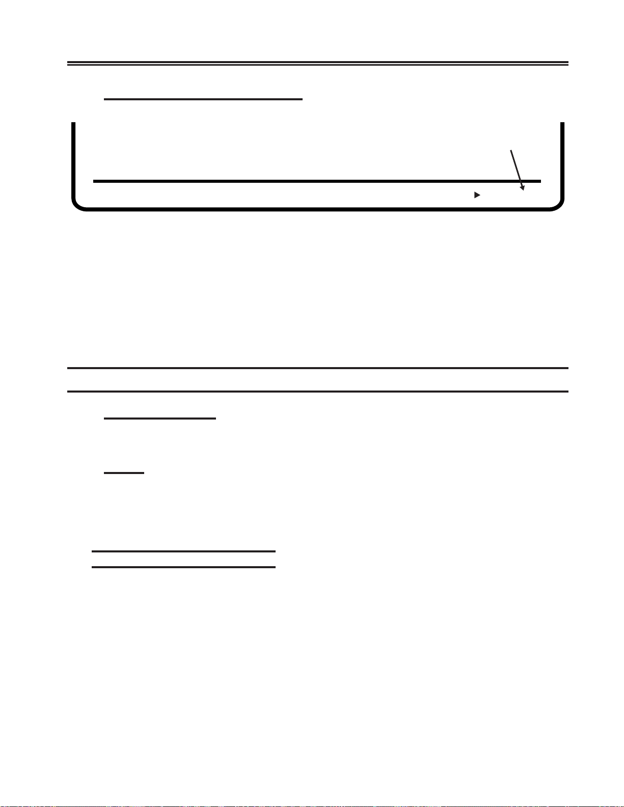
Print/Printer T ype Function
Figure 3-13. Online Print/Printer Type Function
Use the Enter key to select the host printer (
1173 or the 1201. The printer is displayed in the last four fields of the Print/Printer Type
function.
When the printer you want is displayed, press the Up and Down Arrow keys to scroll
forward or backward to the next online setup function or hold down the Alt key while
you press the Setup key (for the 102-key keyboard, hold down the Shift key while you
press the Setup key) to exit from Online Setup mode.
Use of any local screen printer other than the 1173 or the 1201 could produce
unpredictable results and is neither recommended nor supported.
), or one of two local screen printers, the
Printer T ype
1201
3-18 701408-002
Page 38
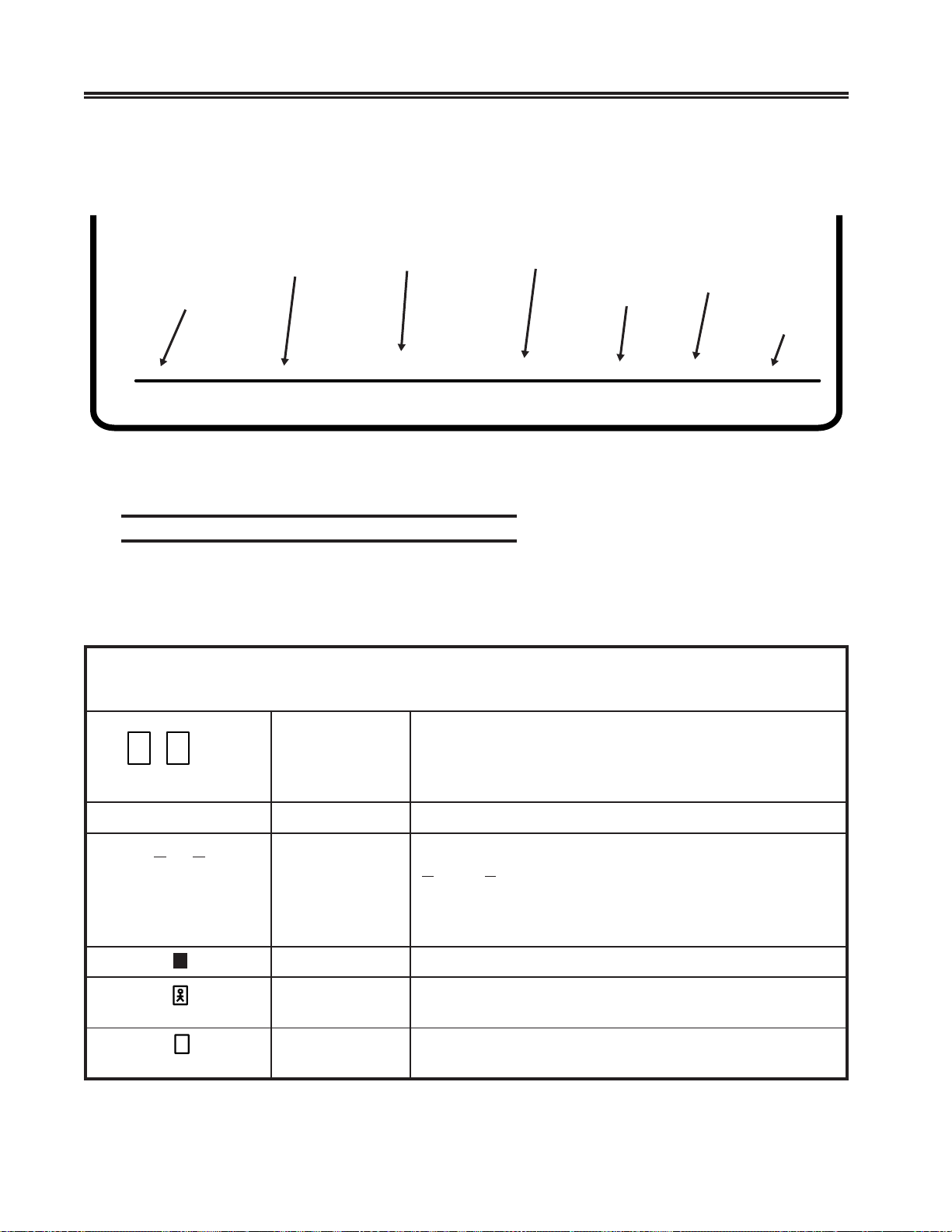
Mark Unprotected Fields Function
Setup Procedures
Mark Unprotected Fields
Turned Off
Use the Enter key to turn Mark Unprotected Fields off or on. 0 (off) or 1 (on) is
displayed in the last field of the Mark Unprotected Fields function.
When your selection for Mark Unprotected Fields is displayed, press the Up and Down
Arrow keys to scroll f orward or backward to the next online setup function or hold do wn
the Alt key while you press the Setup key (for the 102-ke y keyboard, hold down the Shift
key while you press the Setup key) to e xit from Online Setup mode.
Indicators
Power-On Indicator
When lit, indicates that the display station is powered on. See Figure 2-3 on Page 2-5.
Cursor
Figure 3-14. Online Mark Unprotected Fields Function
‘—’
0
After the display station is powered on and warmed up, if it is attached to an inactive
host, a cursor is displayed in the upper left corner of the screen. If the host is active, the
cursor is positioned as specified by the host. As data characters are entered through the
keyboard, the cursor moves to the ne xt a vailable screen character position.
Operator Status Row Indicators
This is the area below the last data row and is separated from the rest of the screen by
one nonintensified line. The operator status ro w contains symbols that indicate current
operating conditions. These symbols can be divided between System indicators and
Local indicators.
701408-002 3-19
Page 39
Setup Procedures
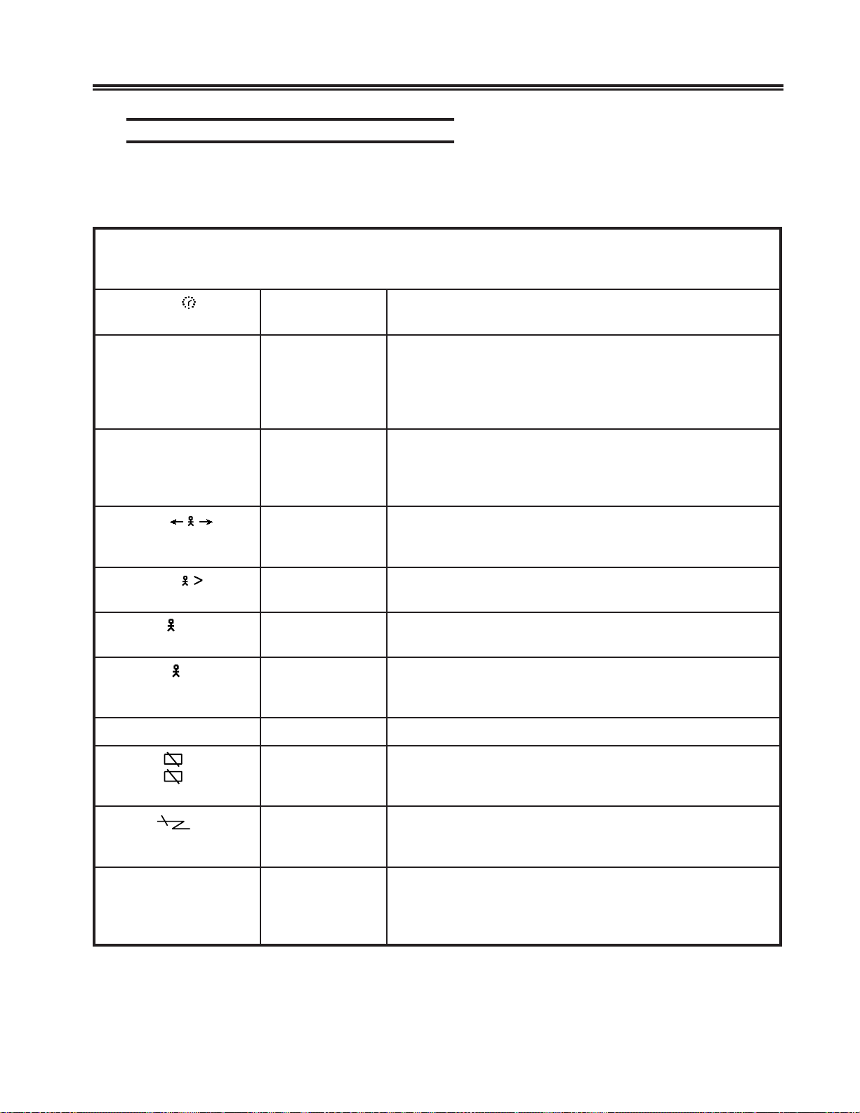
The symbols shown below are generated when the display station is attached to an MTX/
MTC 1174 Network Controller , a Memorex T ele x 1274 Control Unit, a Memorex Telex
1374 Control Unit, an IBM 3274 Control Unit, or an IBM 3174 Control Unit.
Input
Inhibited
Readiness
and System
0–8 9–17 21–30 36–45 53 66–68 71–80
Figure 3-15. System Operator Status Row Fields
Reminders
Column Numbers
Shift and
Modes
Coax
Printer
Status
Local
Printer
Status
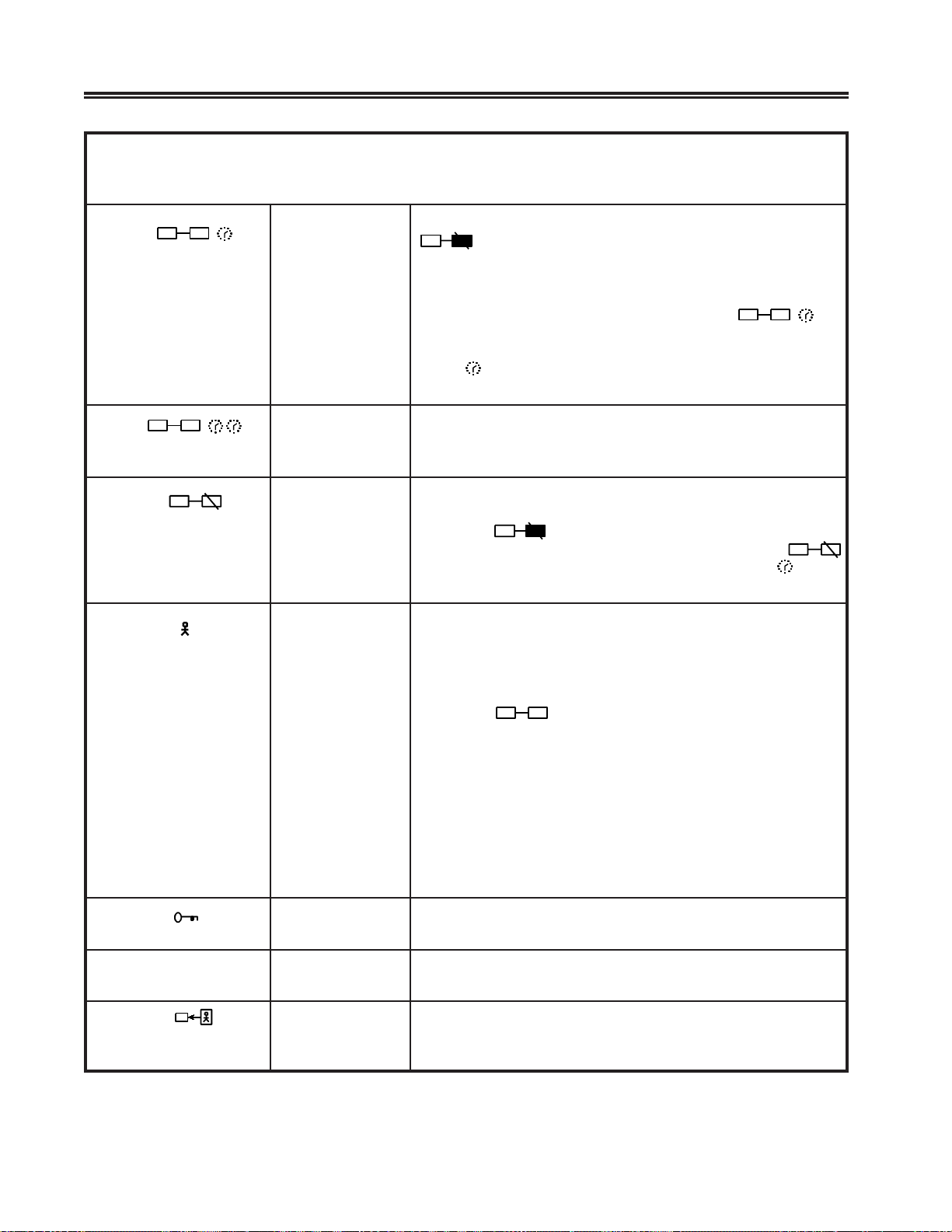
Readiness and System Connection Symbols
These symbols, either alone or in combinations, indicate the readiness status of your
display station, control unit, and system.
SLOBMYSNOITCENNOCMETSYSDNASSENIDAER
Device–
Dependent
Symbols
64
,
iroI
roB
A
?
lobmySemaNgninaeM
tinUlortnoC
or S
ydaeR
ydaeRXX34MBI.noitatsyalpsidehtotdetcennocsimetsysXX34MBInA
BroAenilnOAselurenilnorednumetsystsohotdetcennocsitinUlortnoC
boJyM.margorpnoitacilpparuoyhtiwgnikrowsinoitatsyalpsiD
rotarepOmetsySlortnoc(rotarepometsysotdetcennocsinoitatsyalpsiD
denwonUehtottontub;metsystsohotdetcennocsinoitatsyalpsiD
(A
(Bro)B lortnocdnanoitatsyalpsidnrevogselurenilnO.)
.worsutatsrotarepo
.)margorp
4723MBI,4731xeleTxeromeM,4721xeleTxeromeM
lortnoC6723MBIro,471xeleT,672xeleT,)4(tinUlortnoC
4713MBIro,rellortnoCkrowteN4711CTM/XTM,)6(tinU
.noitatsyalpsidehtotdetcennocsitinUlortnoC
elbacilppafoteseht;metsystsohehthtiwsnoitcasnarttinu
ehtnislobmysemosfogninaemehtegnahcyamselur
.margorplortnocronoitacilppa
3-20 701408-002
Page 40
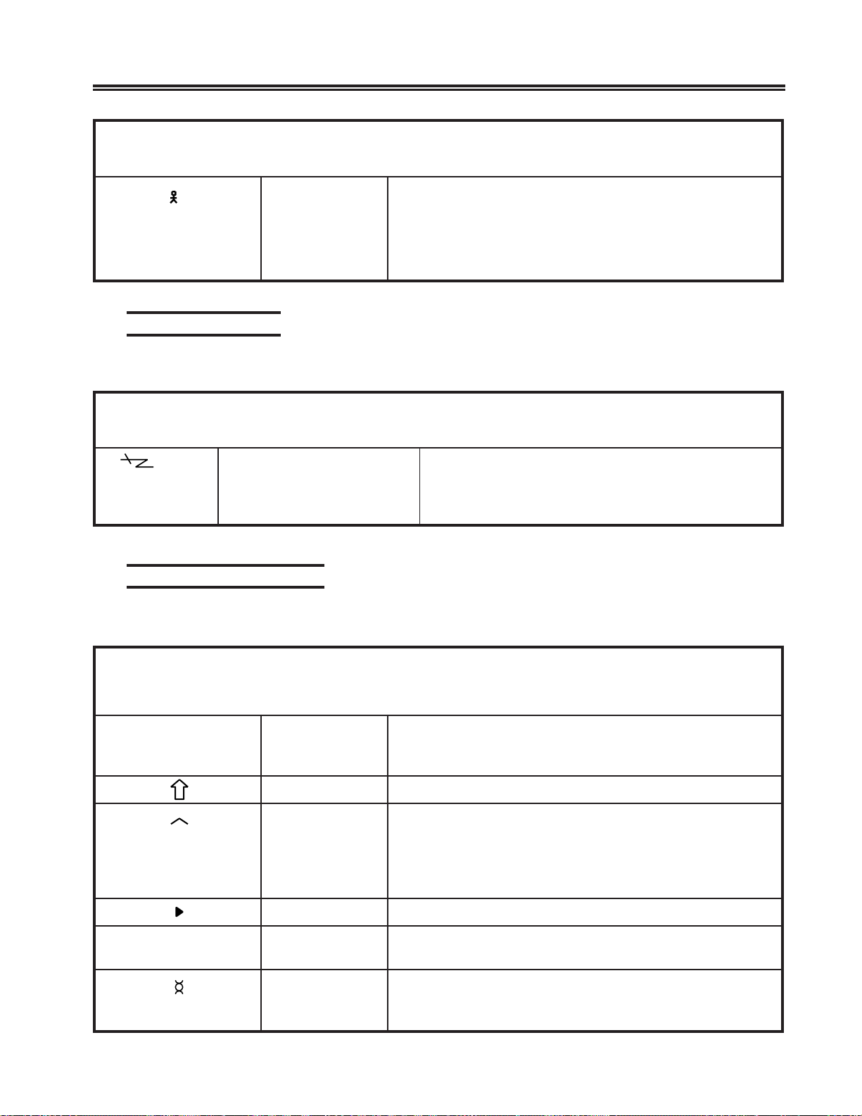
“Do Not Enter” (Input Inhibited) Symbols
The X (Do Not Enter) symbol indicates that your display station will not accept input
from your keyboard. Additional symbols are display ed to the right of the X to explain
why your input is not accepted.
lobmySemaNgninaeM
Setup Procedures
SLOBMYS)DETIBIHNITUPNI(”RETNETONOD“
X
X?+
X SYSTEM
X
X
X
NUM
X
?#
emiTevahuoynoitcnufmrofrepotemitseriuqermetsystsoH
.detelpmocebotnoitcnufehtroftiaW.detseuqer
?tahWehtybdetpeccatonsawdetpmettauoynoitarepotsalehT
ehterusneotnoitatsyalpsidruoykcehC.noitatsyalpsid
dnayekteseRsserP.tcerrocsimrofrepottnawuoynoitarepo
detaeper,desusawyeknttAroqeRsySfI.noitarepoyrter
.yrassecenebyamseirter
kcoLmetsySsserproegassemrofkooL.draobyekdekcolsahmetsystsoH
metsySsesumargorptsoh,sledomCLDSnO.yekteseR
txenehtdnesotrotarepoehttseuqerotlobmyskcoL
.egassem
erehweslEoGdilavnirodetcetorpaninoitareponadetpmettaevahuoY
,yekteseRsserP.noitcaekatotnoitisoprehtonaotoG.dleif
.noitarepotaeperdna,rosrucevom
nahTeroMehttcerrocdnayekteseRsserP.dleifsihtrofatadhcumooT
.yrtne
ciremuNsserP.dleifsihtnideretneebyamsretcarahcciremunylnO
.yrtneehttcerrocdnayekteseR
?rebmuNtahW.dleifsihtnideretneebyamsretcarahcciremunniatrecylnO
tonsirebmunDIretnirPdetcelesanehwsraeppalobmyssihT
.yrtnetcerrocdnayekteseRsserP.denifedtonsirociremun
X–f
nn
X
nnn
X
X
5nn
X PROGnnn
kcehC
noitcnuFsuniM.yekteseRsserP.elbaliavanunoitcnufdetseuqeR
kcehCenihcaMyekteseRehtsserP.ylreporpgnitarepotonsinoitatsyalpsiD
noitacinummoC
kcehCmargorPtsohmorfatadnirorregnimmargorpdetcetedtinulortnoC
launamsihtni6retpahCotrefer,srucerrorrefI.revocerot
.noitcaetairporpparof
dnatinulortnocneewtebenilsnoitacinummochtiwmelborP
,srucerrorrefI.revocerotyekteseRehtsserP.metsystsoh
.noitcaetairporpparoflaunamsihtni6retpahCotrefer
yamesunimargorpnoitacilppaehT.yekteseRsserP.metsys
paroflaunamsihtni6retpahCotrefer
p
.noitcaetairpor
701408-002 3-21
,stsisrepmelborpfI.noitatsyalpsidruoyrofenognorwehteb
Page 41
Setup Procedures
lobmySemaNgninaeM
SLOBMYS)DETIBIHNITUPNI(”RETNETONOD“
X
X
X
XX
ysuBretnirPfI.ysubsinoitatsyalpsidruoyotdengissaretnirpxaoC
toNretnirP
gnikroW
rotarepO
dezirohtuanU
ysuByreVretnirPlanoitiddaseriuqernoitarepotnirptahttpecxe,evobasaemaS
X
.hsinifotemit
fI.tseuqer nn ,worsutatsrotarepoehtnotneserpsi
nisignitnirpehtelihwthgirehtnodeyalpsidsi
rohsinifotnoitarepoehtroftiawrehtienacuoy,ssecorp
.yektiuQehtgnisserpybnoitarepotnirpgnidnepehtlecnac
ehtslecnacrodetratstonsahtifitseuqerehtslecnacsihT
X
sesare,detratssahtifibojehtforedniamer
ehtelihwyektiuQehtgnisserP.draobyekehtskcolnudna
lobmyssihtsecalpermetsystsohehtmorfgnitnirpsiretnirp
ybdelecnacebtonnacnoitarepotnirptnerrucA.htiw
.syekteseRdnatlAehtgnisserp
sserP.gnikrowtonsinoitatsyalpsidybdetcelesretnirpxaoC
tnirpehtlecnacdnadraobyekehtkcolnuotyektiuQeht
fI.noitarepotnirptsalehtgniruddeppotsretnirpeht
X
X
sesuacgnitnirpdetseuqer–metsystsoha,tneserpsiot
.setelpmoctnirpehtlitnutiawtsumuoydnaraeppa
detseuqerehtodotdezirohtuatonsinoitatsyalpsidruoY
ehtfoenO.yekteseRehtsserP.noitcnufdetaler–retnirp
otlobmyssihtdesuacsnoitidnocgniwollof
a
:raepp
retnirpehtgniretnetuohtiwdesserpsawyektnirPehT
rorebmun.tneserpsi
.dengissa
ehT
n
X
3
X
–
S
X
kcoLytiruceS”kcoLytiruceScinortcelE“otrefeR.gnikrowsikcolytiruceS
lobmySsuniMsserP.tinulortnocehtybdezingocertonsidepytlobmysehT
devieceRegasseMsserP.detcejerdnadeviecersawrotarepolortnocehtmorfegasseM
.yekteseR
??
retnirponsahtinulortnocehtdnadesserpsawyektnedIehT
tontub,tinulortnocehtybdenifedsideretnerebmu
.noitatsyalpsidehtrofdewolla
yalpsidafostnetnocehtfollatpeccaotelbanusiretnirpehT
.gnitnirplacolgnirudnoitats
.11–4egaPno
.yekteseReht
3-22 701408-002
Page 42
lobmySemaNgninaeM
Setup Procedures
SLOBMYS)DETIBIHNITUPNI(”RETNETONOD“
*+?
X
dilavnI
Reminder Symbols
These messages are a reminder that a condition has occurred.
lobmySemaNgninaeM
5nn
Shift and Mode Symbols
erehw(noitanibmocyek–retcarahc/yek–daeddilavninA * si
yeK–daeD
noitanibmoC
.niaganoitanibmoc
SLOBMYSREDNIMER
rednimeRsnoitacinummoCsiknilsnoitacinummocmetsystsoh/tinulortnoC
,rebmunrorreehT.metsys nn ro nnn epytehtsetacidni,
.melborpnoitacinummocfo
snoitatsyalpsidno(deretnesaw)retcarahctneccana
,hcnerFnaidanaC,hsinapS,hcnerFrofderugifnoc
ehtsserP.)ylnosnoitacilppahcnerF/ssiwSdna,namreG/ssiwS
yek–retcarahc/yek–daedehtretnednayekteseRroqRsyS
ehthtiwgnitacinummoctonerauoY.srorregnicudorp
These messages indicate the shift and mode your keyboard is using.
SLOBMYSEDOMDNATFIHS
lobmySemaNgninaeM
MUN
A
ciremuNnisidraobyekehtdnanosinoitcnufkcoLciremuNehT
).etareposyekpuD
tfihspU.edomtfihSnisidraobyeK
tresnIdetresniebyamretcarahcA.edomtresnInisinoitatsyalpsiD
tceleSdednetxE.edomtceleSdednetxEnisinoitatsyalpsiD
kcoLspaCsaraeppasretcarahcdetneccadnasretcarahccitebahplA
.sretcarahcesacreppu
miDotuAtonsahnoitatsyalpsidehtrodesserpneebtonsahyekA
dna,)-(suniM,).(doireP,9hguorht0ylnO(.edomciremuN
ybffodenrutebnacedomtresnI.noitisoprosrucehtta
:syekgniwollofehtfoenognisserp
)Fro(FP,AP,retnE,qRsyS,tseT,teseR
yekynagnisserP.setunimdeificepsehtrofatadynadeviecer
.stnetnocnoitatsyalpsidehtsnruter
701408-002 3-23
Page 43
Setup Procedures
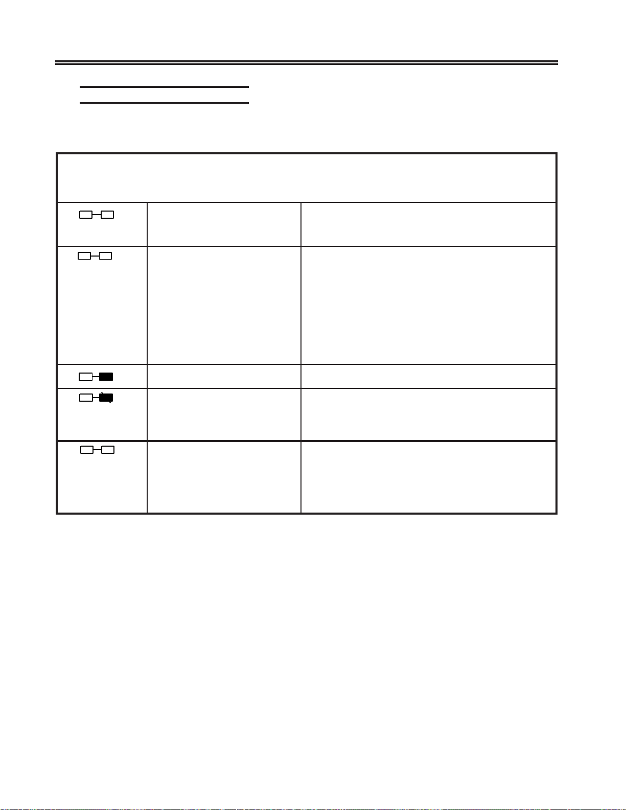
Coax Printer Status Symbols
These messages appear during print operations to indicate where the operation is
performed and the progress of the print job.
lobmySemaNgninaeM
– –
nn
retnirPxaoCngissA ehtgnisserpybdegnahcsissalC/DIretnirpxaocnehW
sAretnirPxaoC
s
tnemngi.nnretnirpxaocesuotdezirohtuasinoitatsyalpsiD
SLOBMYSSUTATSRETNIRPXAOC
ehtmorfderetnesiDIlaremun-owteht,yektnedI
snoitisopdenilrednuehtnideyalpsidsidnadraobyek
sopehT
s
rebmunssalcretnirp–58hguorht07–
.wollofsrebmuntnemngissaretnirpelbi
rebmuntropretnirplaudividni–13hguorht10–
rebmuntropretnirplaudividni–7Ahguorht0A–
rebmuntropretnirplaudividni–7Bhguorht0B–
rebmuntropretnirplaudividni–7Chguorht0C–
rebmuntropretnirplaudividni–7Dhguorht0D–
noitatsyalpsidehtotdehcattaretnirplacol–99–
nn
nn
??
gnitnirPretnirPxaoC.bojruoygnitnirpsiretnirpxaocdetcelesehT
eruliaFretnirPxaoC gnitnirpelihwdeliafsahretnirpxaocdetcelesehT
ehtraelcuoylitnunosniamerlobmysehT.krowruoy
.yektiuQehtsserpronoitidnoc
retnirPxaoCtahW tnedIehtsserP.degnahcsahtnemngissaretnirpxaoC
sihT(.tnemngissaretnirpwenehtyalpsidotyek
dehcattasnoitatSyalpsiD1841nosraeppaylnolobmys
MBInaro,4721xeleTxeromeMa,472xeleTaot
).tinUlortnoC4723
3-24 701408-002
Page 44
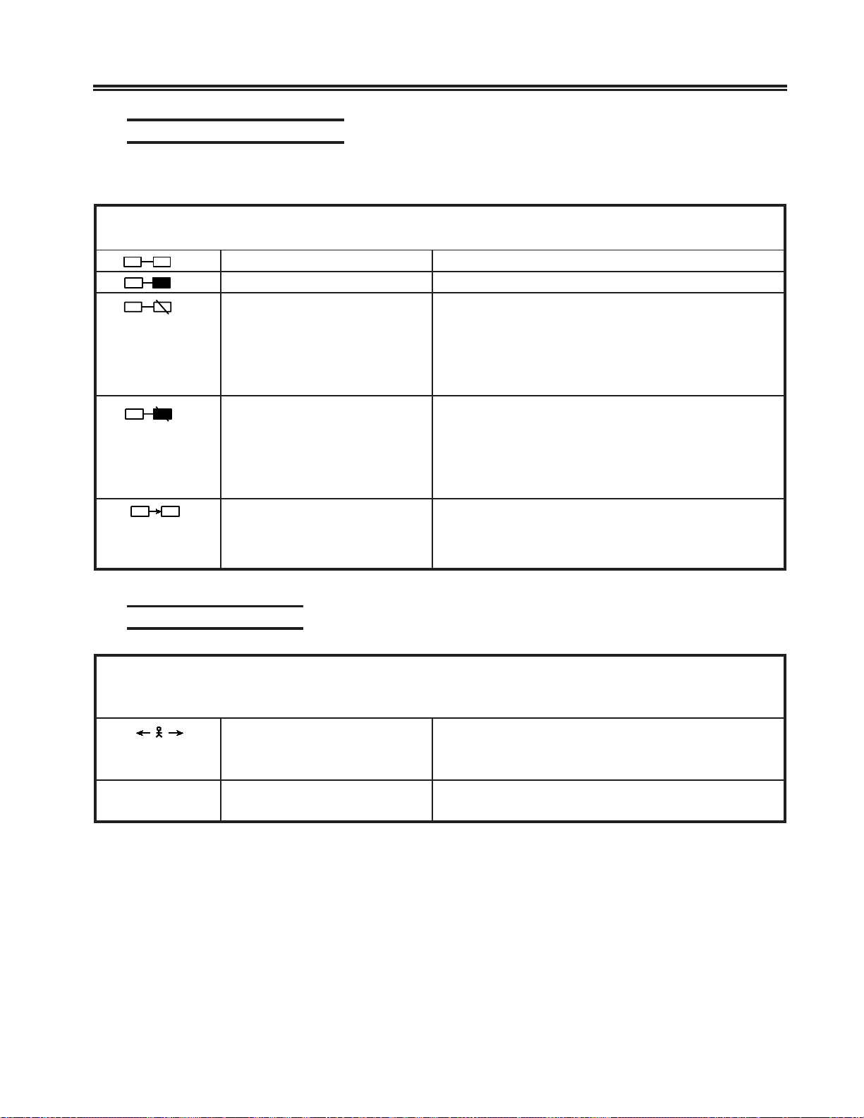
Local Printer Status Codes
These symbols are displayed during local print operations.
lobmySemaNgninaeM
99
99
99
99
X99
nOretnirP.nodnadehcattasiretnirpneercslacolehT
tnirPneercS.bojruoygnitnirpsiretnirpdetcelesehT
evitareponIretnirP
)detseuqerneebtonsahtnirP(
evitareponIretnirP
)detseuqerneebsahtnirP(
dekcoLdraobyeKehT
Setup Procedures
SLOBMYSSUTATSRETNIRP
neebsahtnirpanehwdeyalpsidsilobmyssihT
retnirpehT.evitareponisiretnirpehtdnadetseuqer
ehtxiF.detcelestonro,repapfotuo,demmajebyam
tonnacnoitatsyalpsidehT.esuroftitcelesdnaretnirp
silobmyssihtelihwedomputeSnidecalpeb
.deyalpsid
neebsahtnirpanehwdeyalpsidsilobmyssihT
retnirpehT.evitareponisiretnirpehtdnadetseuqer
ehtxiF.detcelestonro,repapfotuo,demmajebyam
tonnacnoitatsyalpsidehT.esuroftitcelesdnaretnirp
silobmyssihtelihwedomputeSnidecalpeb
.deyalpsid
id
neercsehtotatadgnirrefsnartsinoitatsyalps
atadehtlitnudekcolsniamerdraobyekehT.reffub
ebtonnacnoitatsyalpsidehT.detelpmocsirefsnart
.deyalpsidsilobmyssihtelihwedomputeSnidecalp
Local Error Indicators
lobmySemaNgninaeM
KdnaL
SROTACIDNIRORRELACOL
tnemevoMrosruCdilavnI neercsehtfotuorosrucehtevomotdetpmettauoY
rosrucehtevoM.aeratnirpehtgnitteselihwaera
.lobmysehtraelcotaeraneercsehtnihtiw
rorrEnoitatSyalpsiD .stnemelestinirorrenadetcetednoitatsyalpsidehT
.noitamrofnieromrof6retpahCotrefeR
701408-002 3-25
Page 45
Setup Procedures
Entry Assist Indicators
lobmySemaNgninaeM
COD
Response Time Monitor Indicators
edoMtnemucoD eromroF.edomtnemucoDnisinoitatsyalpsidehT
parWdroWsinoitcnuf)enilwencitamotua(parWdroWehT
SROTACIDNITSISSAYRTNE
”.tsissAyrtnE“,5retpahCotrefer,noitamrofni
,5retpahCotrefer,noitamrofnieromroF.delbane
”.tsissAyrtnE“
SROTACIDNIROTINOMEMITESNOPSER
lobmySemaNgninaeM
.
.
t.ss
ss:mm
???
epyTtrohSebotatadtsalehtrofderiuqeremitehtsetacidnI
epyTgnoLebotatadtsalehtrofderiuqeremitehtsetacidnI
dezirohtuanUyalpsiDehtyalpsidotdewollatonsinoitatsyalpsidehT
“t sniamerlobmyssihT.)sdnocesfoshtnetrof”
.deyalpsidsi
“ ss litnudeyalpsidsniamerlobmysehT.)sdnocesrof”
delecnaCyalpsiDsawtnemerusaememiTesnopseRtnerrucehT
.delecnac
lortnocehthguohtla,metsystsohehtybemitesnopser
.rotinoMemiTesnopseRehtdelbanetinu
“(metsystsohehtotdettimsnart ss dnasdnocesrof”
lobmysrotinoMemiTesnopseRwenalitnudeyalpsid
“(metsystsohehtotdettimsnart mm dnasetunimrof”
.deyalpsidsilobmysrotinoMemiTesnopseRwena
3-26 701408-002
Page 46

Chapter 4. Operating Procedures
The operating procedures described in this manual work for a 1481 that is attached to a
powered, operational control unit or processor . Refer to Chapter 1 for a list of compatib le
control units and processors. Before operating the display station, ensure that it is
connected to the control unit.
Preparation for Operating
After the display station has been installed and is connected to its control unit, it is ready
to operate online. To ensure that your display station is prepared to operate, perform
the following procedure. Refer to Chapter 6 for further information if the display
station does not operate or malfunctions.
1) Turn the security lock key clockwise to unlock the k eyboard.
2) Turn the power on by setting the P o wer-On/Of f switch to On ( | ).
3) An alarm sounds briefly. The cursor appears in the upper left corner of the screen
and the operator status row displays the Ready symbol:
6
– If attached to a Telex 276 Control Unit/Displa y Terminal, or IBM 3276
•
Control Unit Display Station
4
– If attached to a Memorex Telex 1274, a Memorex Telex 1374, a Memore x
•
2274, or an IBM 3274 Control Unit
• I or i – If attached to an IBM 4300 processor
• S – If attached to a MTX/MTC 1174 Network Controller or IBM 3174 Control
Unit).
The Power-On indicator is lit.
Note: See “Operator Status Row Indicators” on Page 3-19 for explanations of
all operator status row symbols.
4) If the Power-On indicator fails to light, the cursor fails to appear, or a display like
the one described above is not produced, refer to Chapter 6 of this manual.
If “B” is displayed in the first character position of the operator status row , refer to
Chapter 6 of this manual.
5) Adjust the Contrast and/or Brightness controls for viewing comfort.
701408-002 4-1
Page 47
Operating Procedures
Assigning a Coax Printer
Each display station in a system configuration can be assigned a host printer that can
generate copies of information displayed on the screen. These copies can be used to
maintain records of display station/CPU transactions.
For 88-key, 102-key, 104-key, and 122-key k e yboards, press and hold the Alt key, then
press the Ident key to display the Assign Printer condition symbol
operator status row . For 102-ke y ke yboards, press and hold the Shift key, then press the
Ident key to display the symbol.
– –
in the
Note: If
screen printer. This allows you to assign the coax printer.
Consult your supervisor for an available coax printer’s ID number and enter that
two-digit ID number. The two-digit number replaces the underscore positions on
the operator status row. Once the printer’s ID number is entered, the sequence
ends automatically .
If an invalid ID n umber is entered for a host printer , the “What?” symbol (
on the operator status row . If this occurs, press the Reset ke y and try another number .
99
is displayed on the operator status row when the Ident key is pressed,
does not display. Enter Setup mode and select host pr inter instead of
– –
Data Entry Function
The data entry function consists of writing data messages in an acceptable form for
computer processing. As messages are enter ed through the keyboard, they are displayed
on the screen either as unformatted information or according to a program-determined
format. Attributes of the formatted screen f ields control the amount and type of entered
data (alphanumeric or numeric).
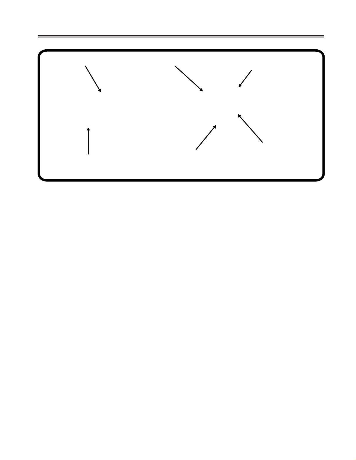
Figure 4-1 on Page 4-3 shows a typical formatted screen. All fields on the screen are
preceded by a nondisplayed attribute character and are defined as protected or unprotected (entry) fields. For protected f ields, the application program fills in the information
following the attribute characters. Attempts to change displayed information in a protected field cause a “Go Elsewhere” condition symbol (
status row . The unprotected (or entry) fields accept ne w or re vi sed information from
the operator. Some application programs fur ther designate an entry field by displaying
the cursor in the unprotected field’ s first character position.
X?+
) appears
X
) to appear on the operator
4-2 701408-002
Page 48
Operating Procedures
Protected Field
+
+
+
Attribute Character
(not displayed)
ORDER #
NAME
PART #
Cursor
Numeric Field
+
+
ABC CO 314
705163–12
+
Unprotected Field (Entry)
Alphanumeric Field
Figure 4-1. Typical Formatted Screen
Unprotected fields are classified as either alphanumeric or numeric. Alphanumeric
fields can accommodate both alphabetic and numeric data characters. Numeric fields
are controlled by the application program so that attempts to enter characters other
than digits 0 through 9, a period, a Dup key, or a minus sign result in an error. On
international keyboards, the comma can be entered instead of the period. Display
stations with Data Entry keyboards automatically shift into Numeric mode when the
cursor enters a numeric field.
Data characters in unprotected fields can also be displayed as intensified (brighter) fields.
In applications requiring use of confidential information, both the protected and unprotected fields can be programmed to be nondisplayed fields.
Note: Use of nondisplayed fields precludes visual verification of entered data before
transmission to the CPU.
Before you can begin entering data characters on the screen, the display station must
access the CPU and its application program. Access is usually accomplished through use
of the Attention, Progr am Access (PA), Program Function (PF), Clear, or Enter key, or
through a series of sign-on commands and programmed CPU responses. This series is
initiated when the display station comes online. Contact your supervisor or refer to a
system user’s guide f or appropriate program-accessing procedures.
701408-002 4-3
Page 49

Operating Procedures
Keyboard Operations
The description of keystroke functions and operations initiated from the k eyboard
in this section applies to display stations attached to 88-key, 102-key, 104-ke y, or
122-key keyboards. If symbols are different from keyboard to keyboard, all are
illustrated in the text. The symbols for each function can be found on the keyboard
attached to your display station. Remember that legends that appear on the key
face are Alt functions and leg ends that appear on the key top can be shifted or
nonshifted functions as illustrated in Figure 3-1 on Page 3-3.
Moving the Cursor
The cursor always indicates the next available c haracter position on the screen. For
applications using an unformatted screen, the operator selects where the next character
is to be entered by moving the cursor to the desired screen position. The following k eys
are used for positioning the cursor:
Press the Up key (
Press the Down key (
Press the Left key (
depression.
Press and hold the Alt and Left keys (
the cursor moves beyond the edge of the screen, it “wraps” or reappears at the last character position of the previous line.
Press the Right key (
depression.
Press and hold the Alt and Right keys (
When the cursor moves bey ond the edge of the screen, it “wraps” or reappears at the first
character position of the next line.
Press the New Line key (
When the cursor is at the last entry position on the bottom line of the screen, pressing the
New Line key will move the cursor to the f irst entry position at the top of the screen.
Press the Backspace key (
) to move the cursor up the screen.
) to move the cursor down the screen.
) to move the cursor horizontally left one space for each
) to move the cursor left at double speed. When
) to move the cursor horizontally right one space for each
) to move the cursor right at double speed.
) to move the cursor to the first entry position in the ne xt line.
) to move the cursor backward.
Press the Home key to move the cursor to the first available character position on the
screen (Alt–
Alt–
on the 104/122-key keyboards).
on the 88-key keyboard, Home on the 102-key keyboard , and
4-4 701408-002
Page 50

If the application uses a formatted screen, the following k eys can be used for positioni n g
the cursor:
• Press the Tab key ( ) to move the cursor forward to the first entry position of the
next entry field.
• Press the Backtab key ( ) to mov e the cursor back to the first entry position in the
current or preceding entry field.
• Press the Skip key (Data Entry keyboards only) to mo v e the cursor to the f irst entry
position in a subsequent entry field.
For applications using unformatted screens, pressing the Tab, Backtab, or Skip key
returns the cursor to the first available character position on the screen.
Entering Data Characters and Selecting Modes
Alphabetic, numeric, and special characters can be entered to compose data messages on
the screen by pressing their corresponding keys.
After filling the last data line of the screen, the cursor automatically returns to the first
available character position, and entry of additional data may write over an y previously
entered characters. T o pre v ent loss of previous entries, transmit the data message to the
CPU whenever the screen has been completely filled with data. Refer to the “Message
Transmitting Function” on Page 4-8 for additional information.
Operating Procedures
Uppercase characters or the upper characters on dual-character keys are entered by
selecting the Shift or Numeric mode before the key is pressed. On Data Entry keyboards,
enter alphabetic characters in numeric fields by using the Shift (
(see “Numeric Lock Mode” on Page 4-6).
) and Alpha ( ) keys
Shift Mode
Hold the Shift key ( ) while entering data to select upper characters on dual-character
keys or uppercase characters for alphabetic keys; or pr ess and release to turn off the Shift
Lock feature for keyboards with typewriter layouts. Shift mode is designated on the
operator status row by the
Press the Shift Lock key (
keyboards, press the Shift key to unlock. For Data Entry ke yboards, press the Shift Lock
key again to exit Shift mode. F or 102-key ke yboards, use the Caps Lock key in place of
the Shift Lock key .
symbol.
) to lock the keyboard into Shift mode. For Typewriter
701408-002 4-5
Page 51

Operating Procedures
Numeric Lock Mode
Numeric Lock mode is set or reset in Offline Setup. The Numeric Lock feature allows
fields to be defined to accept only the entry of the digits 0 through 9, Period (.),
Minus (-), and Dup keys (and comma [,] on some international keyboards). When
the cursor enters a numeric field, the NUM symbol appears on the operator status
row, and only the permitted characters can be entered. If you attempt to enter
nonnumeric characters in a numeric field, the keyboard locks. Locking the keyboard
turns off the keyboard click if it was on, and turns the keyboard click on if it was off.
Press the Reset key to restore normal operation.
On T ypew riter keyboards, the display station goes into lowercase mode when the cursor
enters a numeric field. On Data Entry keyboards, the display station goes into uppercase mode when the cursor enters a numeric field.
Nonnumeric characters can be entered in numeric fields by doing the following:
For Data Entry keyboards and Typewriter keyboards, press the Shift key (
uppercase characters in a numeric field.
For Data Entry keyboards only , press the Alpha key (
acter in a numeric field.
Note that using the Shift Lock key does not override the Numeric Lock feature.
See “Numeric Lock” on Page 3-9 for information on how to set the Numeric Lock.
Cursor Select Data Entry
The Cursor Select key , Cr Sel (Cursr Sel for 88-k ey keyboards), can be used to select
certain data fields from a formatted screen. The application program must define
selectable fields by writing the appropriate attribute. These data fields are read by
the application program for additional processing.
Each selectable data field is preceded by an appropriate field attribute character and a
designator character . Designator characters precede one of two types of fields: selection
fields and attention fields. Items in a selection field can be selected with the Cursor
Select key and the program can be notified of the selection by selecting an attention
field.
A nonselected selection field is preceded by a question mark (?) that changes to a
greater than symbol (>) when the field is selected. Attention fields are preceded by an
ampersand (&) or a space. These symbols do not change when an attention field is
selected.
) to enter
) to enter any lowercase char-
4-6 701408-002
Page 52

T o select or deselect a field, move the cursor to co ver the appropriate designator character
or any character in the field and press the Cursor Select key. The question mark preceding a field changes to a greater than symbol. If the wrong field is selected, it can be
deselected by pressing the Cursor Select key again in the same field. The greater than
symbol preceding a field changes to a question mark after the field has been deselected.
For some programs, when you finish selecting fields, press the Enter key to send the
fields to the host application program for further processing. The selected fields can also
be sent by selecting an attention field designator character using the Cursor Select key.
The ampersand and space characters designate attention fields. Mo ve the cursor to cover
any character in the field and press the Cursor Select key to send the attention f ield data
along with data in any other selected field on the screen.
Exiting the Cursor Select operation depends on the program in use. Refer to a user’s
guide for your application for the proper procedure.
Data Editing Function
After a data message has been composed, you can change the information before sending it to the CPU or you can call up previously entered data messages for editing.
Operating Procedures
Use the Attention, PA, PF , F, Clear, or Enter key to call up previously entered data messages, or use a series of sign-on commands and programmed CPU responses. This series
is initiated when the display station comes online. Contact your supervisor or refer to a
system user’ s guide for appropriate recalling procedures.
All keys described in “Data Entry Function” on Page 4-2 can also be used in editing data
messages. In addition, the following ke ys can be used to add or delete information:
Press the Insert key (
characters at the cursor’s current position. Press Reset to e xit Insert mode. The symbol
appears on the status row to indicate the display station is in Insert mode.
Press the Delete key (
cursor’s current position. The remainder of the line shifts one character position to the
left.
Hold down the Alt key while you press the Delete Word key (
102-key keyboard) to delete a word beginning at the current cursor position. This key
combination is functional only if the control unit to which your display station attaches
supports the Entry Assist feature.
Press the Erase to End of Field key (ErEOF) (Erase EOF on the 88-key keyboard) to
erase all entry field positions from the cursor’s current position to the end of field. The
cursor does not move from its current position.
) (Insert on the 102-key keyboar d) to enter Insert mode and add
) (Delete on 102-key keyboard) to remove a character at the
) (DelWd on the
701408-002 4-7
Page 53

Operating Procedures
Hold down the Alt key while you press the ErInp key (Erase Input on 88-k ey keyboards)
to erase all entry field positions and move the cursor to the first available character
position.
Hold down the Shift key (
move the cursor to the first entry position of the next entry field.
Hold down the Field Mark key , or the Shift ke y (
to enter a character that marks the end of an input field.
) while you press the Dup key to repeat entered data and
Message Transmitting Function
After you have filled all character positions on the screen, send the displayed information to the CPU before continuing data entry . When a data character is entered in the
next-to-last character position on the screen, the audible alarm sounds to remind you
that the cursor is near the end of the screen. If you continue to enter data, the cursor
“wraps” and reappears in the first available character position of the screen. Subsequently entered characters replace displayed characters, resulting in loss of previous
entries.
After filling all required character positions on the screen, press the Enter key to request
a communications line for sending displayed data to the CPU.
Press the Clear key to erase all displayed data on the screen, return the cursor to the first
available character position, and signal the CPU that a “clear” operation has occurred.
The application program in use determines specific functions of the Program Access
(P A) and Program Function (PF or F) keys. Contact your supervisor or refer to a system
user’s guide for further information re garding these keys.
) while you press the Field Mark key,
Press a Program Access key to initiate a program-determined function. Program Access
keys are designated by numbers P A1, PA2, and PA3.
Press a Program Function key to initiate a program-determined function. Program
Function keys are designated by numbers PF1 or F1 through PF24 or F24.
As described in “ Assigning a Coax Printer” on Pag e 4-2, you can assign a printer in the
system configuration that generates copies of information displayed on the screen. The
following procedure explains how to initiate a pr int operation on a coax printer .
After entering data on the screen, press the Print key to send data to the assigned coax
printer for generating copy.
Press the Alt and Reset keys to cancel a pending request by the Print key and restore
keyboard operation. If the assigned printer is not operating, press the Alt and Reset k eys
to restore keyboard operation and reset the
The display station also can be used to send system request messages to the CPU,
depending on the online rules condition symbol that appears in the operator status row.
condition symbol.
4-8 701408-002
Page 54

If online rules A a pply (A appears in the operator status row), press the Alt and Sys Rq
(System Request) keys to send the CPU a message that the display station may be failing
or that a test request message is on the screen. If online rules B apply (
operator status row), press the Alt and Sys Rq keys to clear the display station and
switch the display station between the control (or master) program and application
programs. Contact your supervisor or refer to a system user’s guide for further infor mation regarding this key combination.
Print Function
The display station can send a print request to the host system or it can print data locally
if it is attached to a local screen printer. A desktop/screen printer must be ordered
separately. To access either host printing or local screen printing, enter Setup mode
and specify the Print mode. (See Setup mode procedures in Chapter 3.) Press the Print
key to initiate the print function.
Extended Select Function
There are two Extended Select functions, Entry Assist and the Response Time
Monitor (R TM).
Operating Procedures
B appears in the
Entry Assist
The Entry Assist function f acilitates the creation and editing of text, such as memos, letters,
and documents. For more information on the Entry Assist function, see Chapter 5.
In order to use the Entry Assist function, the control unit to which your display station is
attached must provide Entry Assist support. Consult your control unit operator’ s manual
for further Entry Assist specif ications and operating procedures.
Response Time Monitor
The Response Time Monitor (RTM) records the speed of communications between
the devices attached to a valid, properly configur ed control unit (Memorex T ele x 1274
or IBM 3274) and the host CPU to which they are attached. The R TM is accessed and
exited by pressing the Extended Select key (ExSel for 104- and 122-key keyboards,
Alt-ExSel for 102-key keyboards, and EXSEL for 88-key keyboar ds), followed by the
PF19 or F19 key. Consult your control unit oper ator’s manual for further specifications and operating procedures.
701408-002 4-9
Page 55
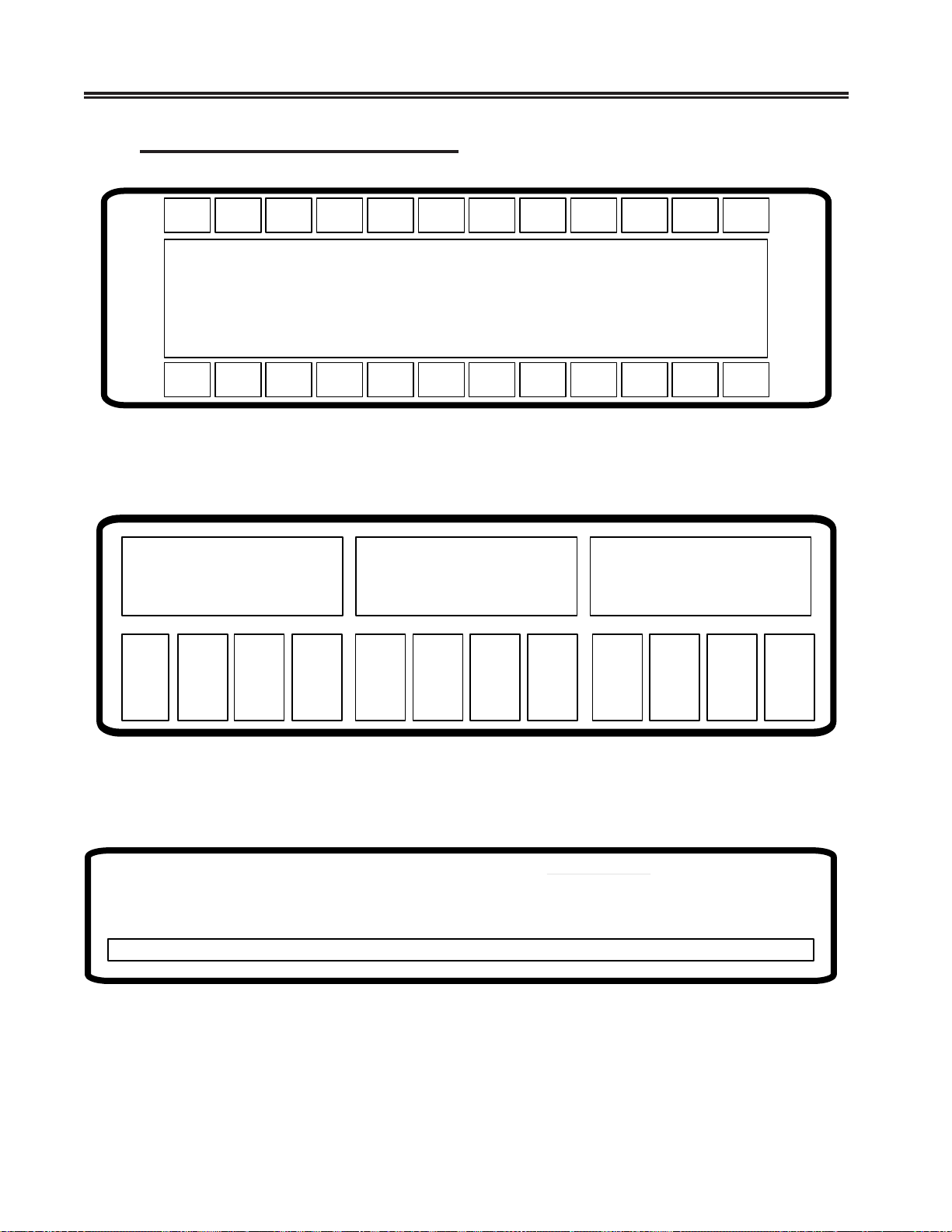
Operating Procedures
Extended Select Keyboard Overlays
Exsel
Exsel
Doc
On/Off
Doc
On/Off
Wrap
Wrap Chg
Fmt
Chg
Fmt
RTM
Figure 4-2. Extended Select Function Overlay
(104-Key and 122-Key Keyboards)
CrPos
Rtm
Figure 4-3. Extended Select Function Overlay
(102-Key Keyboards)
EXSEL Functions
PF13=DOC ON/OFF
PF14=WRAP
PF15=CHG FMT
PF16=WSC
PF19=RTM
PF22=CR POS
Figure 4-4. Extended Select Function Overlay
(88-Key K eyboards)
4-10 701408-002
Page 56

Using the Light Pen to Select Data
Y ou can use the optional light pen to select data from fields that are def ined for light pen
operations. Ask y our supervisor to tell you which fields on the panels you use are set up
for light pen selection.
Follow these steps to select an item with the light pen:
1) Press the light pen to the screen on the field you want to select.
2) If you have turned on the light pen click, a click occurs when the field is selected.
3) If the field is preceded by ?, the ? changes to > when the field is selected.
4) If the field is preceded with &, processing begins as soon as you select the item.
5) If necessary, complete the selection by pressing a keyboard key (for example,
Enter) or perform an additional light pen selection (like pointing to an End
command) to conclude.
Electronic Security Lock
Operating Procedures
To invoke the secure (locked) mode, the operator enters the Lock sequence (Right
Alt key, Right Shift key, and Enter key). The control unit displays
line and the terminal adds a 3 to act as a prompt for a user-definable three-key password
to “unlock” the terminal. To Unlock, type in the three-key password. Each key decrements the prompt number. If the password does not match, the 3 redisplays on the
status line. When the password matches, the terminal is unlocked and the control
unit removes the
Powering off the terminal while locked means it will be lock ed when powered on next
time. Upon power-up
unlock the terminal. To change the password, see “Change KEYLESS Password” on
Page 3-10.
symbol.
is displayed, requiring all three password keys to be enter ed to
on the status
701408-002 4-11
Page 57
Description
The Entry Assist function enhances data entry, formatting, and editing on the 1481
Display Station. Access the Entry Assist function with the 104-key and 122-key
keyboards by pressing the ExSel key (EXSEL key for the 88-key keyboard) follo wed by
the PF13 (Document-On/Off) key. For display stations attached to 102-key keyboards,
press the Alt key and the ExSel key followed b y the F1 key. Extended Select mode is
entered when the Extended Select key is pressed. In Extended Select mode, the
following keys become redefined to perform the Extended Select functions.
Note: Entry Assist is a controller feature, available only if the display station is
Chapter 5. Entr y Assist
attached to a controller that supports Entry Assist capability.
sdraobyeKyeK–88
ffO/nOCOD)edoMtceleSdednetxEni(31FP
ffO/nOparWdroW)edoMtceleSdednetxEni(41FP
tamroFegnahC)edoMtceleSdednetxEni(51FP
droWeteleD)yektlAgnisserpelihw(
droWtxeN)yektlAgnisserpelihw(
droWsuoiverP)yektlAgnisserpelihw(
sdraobyeKyeK–221dna,yeK–401,yeK–201
ffO/nOCOD)edoMtceleSdednetxeni(1F
ffO/nOparWdroW)edoMtceleSdednetxeni(2F
tamroFegnahC)edoMtceleSdednetxeni(3F
elihw(dWleD–draobyeKyeK–201
droWeteleD
droWtxeN)yektlAgnisserpelihw(
droWsuoiverP)yektlAgnisserpelihw(
In addition to the format controls supported in Change Format mode and discussed
below , the f ollo wing functions are supported in Document mode:
)yektlAgnisserp
–draobyeKyeK–401/221
)yektlAgnisserpelihw(
• Screen margins
• Tabbing
• Audible alarm that indicates the approach of the end of the line
701408-002 5-1
Page 58

Entry Assist
• W ord wrap that automatically moves an unf inished word to the ne xt line if the word
would extend beyond the right-hand margin
• Autorepeat word-forward and word-reverse cursor mov ement
• Autorepeat character deletion
• Autorepeat character-deleting backspace in Insert mode
• W ord deletion
After formats are established, additional data entry takes place in Document mode with
the entry and editing functions listed above. Once text is entered, it remains in the giv en
format, even if the format is changed later or the display station is taken out of
Document mode.
Entry Assist Functions
This section describes the Entry Assist functions f or display stations attached to 88-key,
102-key , 104-key, and 122-key keyboards.
The Entry Assist functions (formatting controls, cursor movement, and editing functions) are activated by entering Document mode (PF13 or F1) and pressing the Change
Format key (PF15 or F3). A format scale a ppears at the bottom of the screen that allows
format parameters to be altered. Cursor movement and editing controls are given to
certain keys upon entry into Document mode.
Entering Document Mode
When the display station enters Document mode, the DOC message is displayed on
the status row. The DOC message disappears when the display station is taken out of
Document mode.
Format Controls
When the display station is in Document mode, press the Change Format key to display
the format scale. This scale appears at the bottom of the display screen. A reverse video
block cursor is displayed on the format scale in the same column position as the chosen
cursor in the display area (the cursor’s vertical position has no ef fect on the format scale
cursor’s position). See Figure 5-1 for an e xample of the format scale.
T o hide the format scale, press the Change Format ke y again.
5-2 701408-002
Page 59
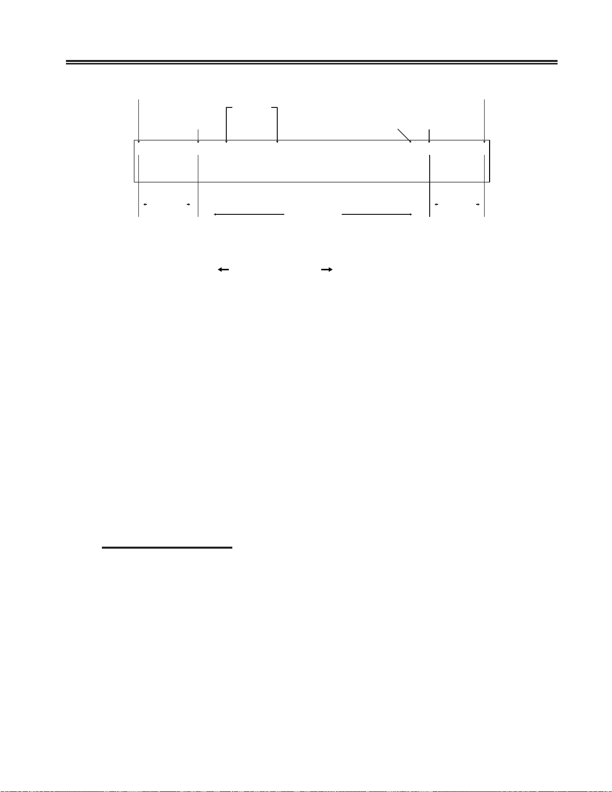
First Screen Column Last Screen Column
Left
Margin
0 — + – - 1 – < – + - _ – 2 — + - _ – 3 — + — 4 — + 5 — + — 6 - * – > — 7 — + —
Tab
Stop End-of-Line
Position Signal
Right
Margin
Entry Assist
Left
Margin
Area
Entry Area
Right
Margin
Area
Figure 5-1. The F orm at Scale
Use the Cursor Left (
) and Cursor Right ( ) keys to mov e the format scale cursor .
Once the format scale cursor is in position, press the appropriate format function key.
When a function key is pressed, the format scale cursor disappears and the appropriate
format symbol is displayed in its place. To make the cursor reappear, press the Cursor
Left or Cursor Right key .
All of the format parameters are saved whenever the display station exits Document
mode. The last values established for the format parameters before exiting Document
mode are in effect when the display station returns to Document mode. The following
format parameters (shown with their corresponding format symbols) can be changed on
the format scale:
• Left margin (<)
• Right margin (>)
• Tab stops ( _ )
• End-of-line signal position (*)
• Alternate right margin type ( | )
• Format scale origin (changes the scale origin from 1 to 0 and vice versa)
Left and Right Margins
To set or move the left or right margin, move the format scale cursor to the desired
position and press the less than symbol (< ) key for the left margin or the greater than
symbol (>) key for the right margin. The symbol is displa yed on the format scale in the
selected position. Only one left margin and one right margin can be defined on the
format scale at a time.
When a margin is redefined, the pre vious margin symbol is replaced by the new symbol.
T ab stops and the end-of-line signal marker are retained, e ven if they are placed outside
the new margins. If the new left margin is to the right of the old right margin, the right
margin is moved to its default position (the far right scale position). If the new right
margin is to the left of the old left margin, the left mar gin is moved to its default position
(the far left scale position). The right mar gin cannot be entered in the left margin default
position, and vice versa.
701408-002 5-3
Page 60

Entry Assist
When data is entered between the margins, the cursor can be located over the left
margin column, and data can be entered in this column. The cursor wraps before it reaches
the right margin column. Data cannot be entered in this column during normal typing.
Even though a margin is defined and the display station is in Document mode, data can
still be entered to the left of the left margin or the right of the right margin. The left and
right margins are established to stop the cursor during normal data entry. The Cursor
Left and Cursor Right keys allow you to mov e the cursor beyond the margins wher e data
can be entered and modified the same as between the margins.
Alternate Right Margin Type
The standard right margin remains in effect during Document mode whether the Word
Wrap function (described on Page 5-6) is active or not. Some typing situations call for a
margin release in which no right margin is observed. Setting the alternate right mar gin
type allows you to define a right margin that is in ef fect when Word Wrap is on and that
is ignored when W ord Wrap is off.
When the right margin is disabled (the alternate right margin is set and Word Wrap is
turned off), the right side of the screen acts as the right margin and text wraps at the
screen’s margin, rega rdless of word di visions. When W ord Wrap is turned back on, the
right margin previously in effect is reinstated.
To give an existing right margin the alternate right margin attribute, place the format
scale cursor over the right margin symbol and press the Cursor Select key. The greater
than symbol turns into a broken vertical bar ( ¦ ), indicating that the right margin is
released when the Word Wrap function is turned off. To restor e the standard right
margin, place the cursor over the broken vertical bar and press Cursor Select again. The
greater than symbol (>) returns to the format scale.
Tab Stops
Setting tab stops on the format scale allows the tab keys to function the way the y do on
a typewriter, treating the defined column positions as tab stops. Once they are set, tab
stops are used in Document mode by pressing the Forward T ab (
(
) key to move the cursor to the ne xt tab stop to the right or left.
T ab stops are set by placing the format scale cursor in the desir ed position and pressing
the Forward Tab key. The format scale displays an underscore ( _ ) in the new tab stop
position unless a margin symbol or end-of-line signal symbol is in the selected position.
Even if the tab stop symbol cannot be displayed in a position, the tab function is still in
effect.
Up to 20 tab stops can be defined in any position on the format scale. Attempts to enter
more than 20 tab stops are ignored.
T o clear a tab stop, place the format scale cursor on the tab stop symbol in question and
press the Delete Character key (
tab stops from the format scale at once, press the Clear key. All tab stop symbols are
removed from the format scale.
) (Delete key on the 102-key ke yboard). To clear all
) key or Reve rse T ab
5-4 701408-002
Page 61

End-of-Line Signal
For the end-of-line signal to work, the audible alarm feature must be tur ned on. When the
end-of-line signal is set, the display station sounds the audible alarm as the cursor enters
the selected column position. This function can be used to warn of the approach of the
right bell on a typewriter .
To set the end-of-line signal, place the format scale cursor in the desir ed position
and press the Asterisk (*) key. An asterisk is displayed in the selected position. The
end-of-line signal function is enabled and remains in effect during Document mode
until the asterisk is removed.
T o disable the end-of-line signal function, place the cursor over the asterisk and press the
Delete Character key (
and the function is disabled. If a tab stop is located at the end-of-line signal position,
removing the asterisk also removes the tab stop.
) (Delete on the 102-key keyboard). The asterisk is remo ve d
The Format Scale Origin
The format scale numbers can be shifted so that the scale begins with Position 1 instead
of Position 0. Tab stops, margins, and end-of-line signal positions are not shifted with
respect to the screen when the scale numbers are shifted.
Entry Assist
To change the scale origin, place the format scale cursor at the leftmost position on the
scale and press the Cursor Select key. The numbers on the line are shifted one space to
the left. Pressing Cursor Select again returns the origin to 0.
Cursor Movement and Editing Functions
Cursor movement and editing functions are active whenever the display station is in
Document mode. These functions are subject to the limitations imposed by the format
parameters currently set on the format scale.
The following cursor movement and editing functions are a vailable in Document mode:
• Word wrap
• Autorepeat cursor movement to next word
• Autorepeat cursor movement to previous word
• Delete word to the right
• Autorepeat deletion of character to the right
• T ab function inserting space characters
• Backtab function
• Backspacing with deletion
• New line function observing left margi n
701408-002 5-5
Page 62

Entry Assist
W ord Wrap
The W ord Wrap function is turned on and off in Document mode by pressing the PF14 or
F2 (Word Wrap) key. This parameter, like other format parameters, is saved when the
display station is removed from Document mode and returns to its last state when the
display station returns to Document mode. The Word Wrap symbol (
word wrapping is in effect. W hen the function is on, text entry is subject to word wr apping between the left and right margins.
Word wr apping occurs when a word being entered would extend beyond the right
margin. When the character is entered that would go beyond the right margin, the entire
word is moved down one line and to the left mar gin. If a space is entered in the position
one character left of the right margin, the cursor is moved to the left mar gin of the nex t
line without word wrapping. If the cursor is one space left of the right margin and the
Dup key is pressed, the Dup character appears on the right margin and the Dup function
works as defined outside of Document mode.
The positions previously occupied by the first part of the word are replaced by space
characters. When a word is wrapped to the left margin of the ne xt line, an y null char acters to the left of the left margin are changed to space characters to preserve the format
when it is sent to the host CPU.
) indicates that
Word wrapping does not occur unless the entir e row onto which the word is wrapped
contains only nulls or spaces. In some cases, word wrapping cannot occur. In these cases,
input is inhibited and the status row shows the Too Much symbol (
key must be pressed for further entry . The following conditions prev ent word wrapping:
X
). The Reset
• The word takes up the entire length of the line.
• There is already text on the next line.
• The current line is the last line on the screen.
• The next line begins with a protected field.
If the display station is in Insert mode and a word is inserted on a line, any word pushed
beyond the right margin is wrapped to the next line if the next line contains enough
spaces after its last word or its margins contain enough nulls to make room for the wrapped
word. If the word cannot be wrapped onto the next line, input is inhibited and the Too
Much symbol is displayed on the status row .
Move Cursor to Next Word (Autorepeat)
T o mo ve the cursor to the next w ord, hold do wn the Alt key while you press the Cursor
Right key (
rently in a word at the end of a line, to the first space or null character following the
current word. The cursor does not move into protected fields with this function.
). The cursor moves to the first character in the next word, or, if cur-
5-6 701408-002
Page 63

The cursor moves to the next wor d regardless of the location of the margins. If te xt is
located outside the margins, the cursor moves to the text without reco gnizing the
margins. The cursor wraps to the next row only when there are no more words in the
current row . When the last w ord is reac hed on the last ro w, the cursor is wrapped to the
first word on the fi rst row of the screen.
T o mak e autorepeat continue automatically , hold do wn the Alt and Cursor Right ke ys.
Move Cursor to Previous Word (Autorepeat)
Press and hold the Alt k ey , then press the Cursor Left key ( ) to move the cursor to the
beginning of the current word (or, if already at the beginning of a wor d, to the beginning
of the word to the left). If the cursor is located at the first word on a ro w , it is wrapped to
the beginning of the last word on the previous ro w . If the cursor is located at the top left
position on the screen, it is wrapped to the beginning of the last word on the screen.
T o mak e autorepeat continue automatically , hold do wn the Alt and Cursor Left ke ys.
Delete Next Word
Entry Assist
The Delete Word ( ) key (DelWd key on the 102-key keyboard) is the alternate
function of the Delete Character ( ) key (Delete key on the 102-key keyboard) when
the display is in Document mode. Pressing the Delete Word key erases the character at
the cursor location and the remainder of the word to the right of the cursor . If the cursor
is on the first character of a word, the whole word is erased. If the cursor is on a space or
null, only the space or null is erased. Punctuation and spaces following a w ord are also
erased (unless only part of the word is erased, in which case the space or null remains).
When a word is deleted, the cursor remains in place and subsequent data on the line
moves to the left. Shifting does not occur for attributes, characters to the right of
attributes, or subsequent lines of data. If deletion is attempted on an attribute or a
protected field, input is inhibited and the Go Elsewhere symbol (
on the status row . Press the Reset key to ena ble further entry.
X
) is displayed
Cursor Tabbing
Pressing the Forward Tab ( ) key causes the cursor to move to the ne xt unprotected tab
stop. Intervening unprotected null characters are converted to space c haracters to
pre serve the format when data is transmitted to the host CPU. If the cursor reaches an
unprotected attribute before it reaches a tab stop, it stops at the attribute. If no tab stops
and no attributes are defined, the cursor mov es to the top left position on the screen.
If there are tabs or unprotected attributes on the screen, tabbing does not allo w the cursor
to wrap from the lower right corner of the screen to the upper left corner of the screen.
701408-002 5-7
Page 64

Entry Assist
For some programs, the introduction of additional data (in the form of nulls being
converted into space characters) can cause problems. Verify that a program can be used
with the tab function in Entry Assist before using the tab function with the program.
Backtab Function
The Cursor Backtab function works like the Forward T ab function, except that the cursor
is moved to the previous tab stop or the fir st unprotected character of the current or
previous field. Pressing the Backtab (
changed to spaces when a backtab operation is performed. The cursor does not wrap
from the upper left corner of the screen to the lower right corner .
Backspacing with Deletion
Pressing the Backspace ( ) key in Insert mode deletes the c haracter to the left of the
cursor and causes the cursor to move left one character space. Characters to the right of
the cursor on the same line move one character to the left. Attributes and characters to
the right of attributes do not move.
If the cursor is located at the left margin when the Backspace key is pressed, input is
inhibited and the Go Elsewhere symbol (
the Reset key to resume entry.
) key causes a backtab operation. Nulls are not
X
) is displayed on the status row . Press
New Line Function
Pressing the New Line ( ) key causes the cursor to move down one line and return to
the established left margin. If the left margin is protected, the cursor moves to the first
unprotected position to the right of the left margin. Unprotected null characters to the left
of the left margin are conv erted to spaces as long as there are no fields between the nulls
and the cursor .
If the cursor is on the last row of the screen and the New Line ke y is pressed, the cursor
is positioned on the first row of the screen.
If there are no unprotected locations between the margins, the cursor moves to the left
margin of the first row on the screen.
5-8 701408-002
Page 65

Chapter 6. Problem Determination
and Maintenance
Diagnostic T esting Function
The 1481 Display Station can perform two types of diagnostic tests: offline tests that
check the operation of the display station independent of its attached control unit, and
online tests that check the 1481 as it interacts with the attached control unit. For
purposes of customer problem determination, some offline tests are presented in this
section. For information about online tests, refer to your controller’ s user’s guide.
Offline T ests
The display station temporarily enters Offline T est mode each time it is powered on. The
display station’s own series of Basic Assurance Tests (BATs) are run each time the
display station is powered on. If an error is detected, the alarm sounds and an error
condition may be displayed in row 1, column 1. K is displayed for a keyboard err or and
L is displayed for a logic error.
Hold down a key while simultaneously turning on the Power-On/Off switch to enter
Offline Test mode. From Offline Test mode, you can enter Setup mode to set or change
special controls, such as the Numeric Lock and the Serial Number . Offline Test mode is
also used to determine hardware malfunctions by running tests from the System
Manager menu. Special controls that can be set from the System Manager menu are also
presented here.
System Manager Menu
You can test the keyboard, align the screen, and display information about your display
station from the System Manager menu. To display the System Manager menu, enter
Offline Setup mode and display the Offline Test menu (Figure 2-5 on Page 2-7).
To enter Offline Setup mode, hold down any key while you turn the display station on.
The Offline Test menu is displayed (Figure 2-5 on Page 2-7).
T o enter setup mode when the display station is online, press and hold down at the same
time the Reset key, the Alt key, and the Test key. The Off line Test menu is displayed
(Figure 2-5 on Page 2-7).
701408-002 6-1
Page 66
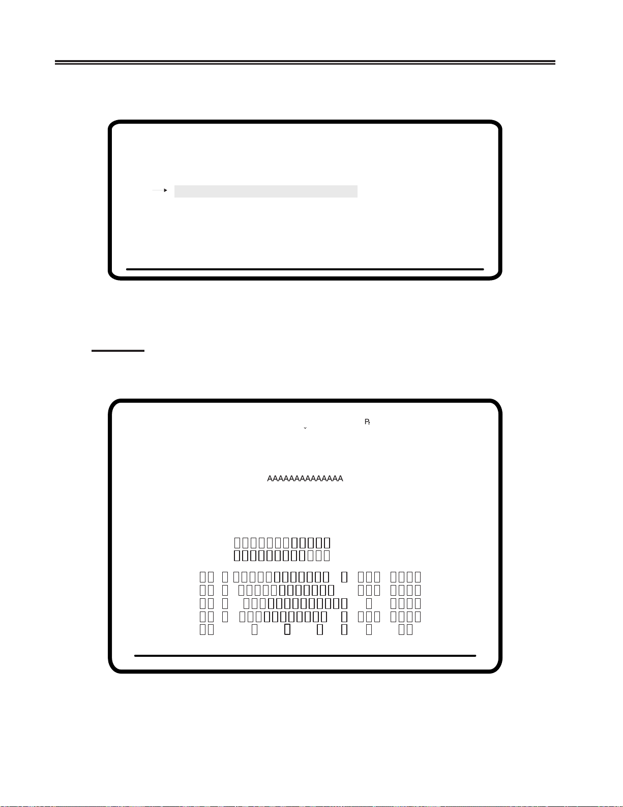
Problem Determination and Maintenance
Use the Up and Down Arrow keys to highlight System Manager Menu and press the
Enter key . The System Manager menu is displayed (Figure 6-1, below).
These screens are for System Managers and service technicians.
Highlighted Tests may destroy data!!
KBD Test
Screen Alignment
NVRAM Counters
Enter Serial # 123456789
Reset NVRAM
Figure 6-1. System Manager Menu
KBD Test
0000 0000
10111000 1111KBD Switches
To test your keyboard, use the Up and Down Arrow keys to highlight KBD Test and
press the Enter key. A keyboard layout like the one below is display ed.
><[])(}{='"/\|¦?!$¢£¥
¬¯º
&-.,:+
АИМТЩГХYAEEIOUYCДЛПЦЬВКОФЫБЙНУЪС
qrstuvwxyzæøåç;
ˆ˜¨`´,аимтщгхяаиймтщьздлпцьвкофыбйнуъс
¯
¯
ABCDEFGHIJKLMNOPQRSTUVWXYZÆ0
*
¤0123456789β§#@%_
abcdefghijklmnop
AAAAAAAAAAAAAA
/
ÅÇ;*
X
Figure 6-2. KBD Test
6-2 701408-002
Page 67
Problem Determination and Maintenance
Note: The keyboard tests for the 88-key and 122-key ke yboards are the same because
the 88-key keyboard imitates the 122-k ey keyboard. If you are testing an 88-k ey
keyboard, the key that toggles on the keyboard test screen may not be the same
key you press on the keyboard.
The actual keyboard layout and the numbers that appear on the display during
the KBD Test may be different from the ones shown in Figure 6-2. The test
display depends on the keyboard type and the switch settings.
Each key on the keyboard can be tested by pressing the key. If the key is operating
correctly, the corresponding key on the display station toggles from an open box to a
filled box and back with each keystroke.
To exit this test and return to the System Manager menu, press the Alt Test key.
Screen Alignment
This test provides a series of test screens to be used by service technicians to adjust
display station parameters. T o display the test screen, use the Up and Down Arrow keys
to highlight Screen Alignment and press the Enter key. A test screen like the one in
Figure 6-3 is displayed. Use the Up, Down, Left, and Right Arrow keys to adjust and
center the data on the screen. Press Reset to return to the System Manager menu.
HEEEEEEEEEEEEEEEEEEEEEEEEEEEEEEEEEEEEEEHHEEEEEEEEEEEEEEEEEEEEEEEEEEEEEEEEEEEEEEH
H
H
H
H
H
H
H
H
H
H
H
H
H
H
H
H
H
H
H
H
H
H
H
H
H
H
H
H
H
H
HEEEEEEEEEEEEEEEEEEEEEEEEEEEEEEEEEEEEEEHHEEEEEEEEEEEEEEEEEEEEEEEEEEEEEEEEEEEEEEH
%%
H
H
H
H
H
H
H
H
H
H
H
H
H
H
H
H
H
H
H
H
H
H
H
H
H
H
H
H
H
H
Figure 6-3. Screen Alignment
701408-002 6-3
Page 68
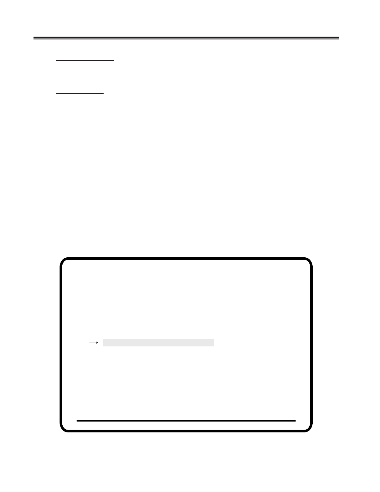
Problem Determination and Maintenance
NVRAM Counter
The NVRAM Counter counts the number of times the NVRAM has been written to.
Enter Serial #
Note: Check with your system operator before changing this value.
Enter your display station’s serial number by using the Up and Down Arrow keys to
highlight Enter Serial # and pressing the Enter key. The n umbers 1–10 and the
alphabet appear above the status row line. Follo w these steps:
Move the underline cursor using the Left and Right Arrow k eys until the ap
1)
propriate
symbol is displayed in the first character image block in the serial number entry
area.
2) Press the Enter key when the underline cursor is located under the character that you
want to select. The entry block automatically moves to the ne xt position in the serial
number entry area and the underline cursor moves under the displayed character .
3) Repeat Steps 1 and 2 until all digits of your serial number are entered. You can
correct the characters you enter when the last character is entered and the cursor
wraps. To clear all entries, press the Clear key.
4) When you complete the entry of your serial number, press the Reset key. The
System Manager menu is displayed.
These screens are for System Managers and service technicians.
Highlighted Tests may destroy data!!
KBD Test
Screen Alignment
NVRAM Counters
Enter Serial # 123456789
Reset NVRAM
0000 0000
10111000 1111KBD Switches
_0123456789ABCDEFGHIJKLMNOPQRSTUVWXYZ
Use Arrow Keys to choose item
Use ENTER Key to change item
RESET Key Exits
Figure 6-4. Enter Serial # Screen
6-4 701408-002
Page 69

Problem Determination and Maintenance
The serial number, along with other Vital Product Data (VPD), is stored in the display
station’s nonvolatile memory and is available to the control unit for system statistics
gathering by some network products. The control unit must be at the appropriate microcode level to support SNA host requests for VPD.
KBD Switches
Select this option to display the current keyboard switch settings. You cannot c hange the
settings from this menu. The keyboard switches are preset at the factory . If y ou need to
change them, contact your local service representative for information on ho w to change
the keyboard switch settings.
Reset NVRAM
T o reset NVRAM and all setup functions to their default settings, use the Up and Down
Arrow keys to highlight Reset NVRAM and press the Enter key . This resets the NVRAM
and counts the NVRAM counter up one to record the reset function.
Note: The default Electronic Security Password is “OPR”.
Leaving the Offline System Manager Menu
Press the Reset key from the Offline System Manager menu to return to the Of fline T est
menu (Figure 2-5 on Page 2-7).
To save the options you set on the Offline System Manager menu, after you leave this
menu you must highlight Go Online on the Offline Test menu and press the Enter key .
Product ID
Display product information by entering Offline Setup mode.
To enter Offline Setup mode, hold down any key while you turn the display station on.
The Offline Test menu is displayed (Figure 2-5 on Page 2-7).
T o enter setup mode when the display station is online, press and hold down a t the same
time the Reset key, the Alt key, and the Test key. The Offline Test menu is displayed
(Figure 2-5 on Page 2-7).
Use the Up and Down Arro w keys to highlight Product ID and press the Enter k ey . The
product number, 1481, is displayed. Press the tab key to display the PROM level.
701408-002 6-5
Page 70
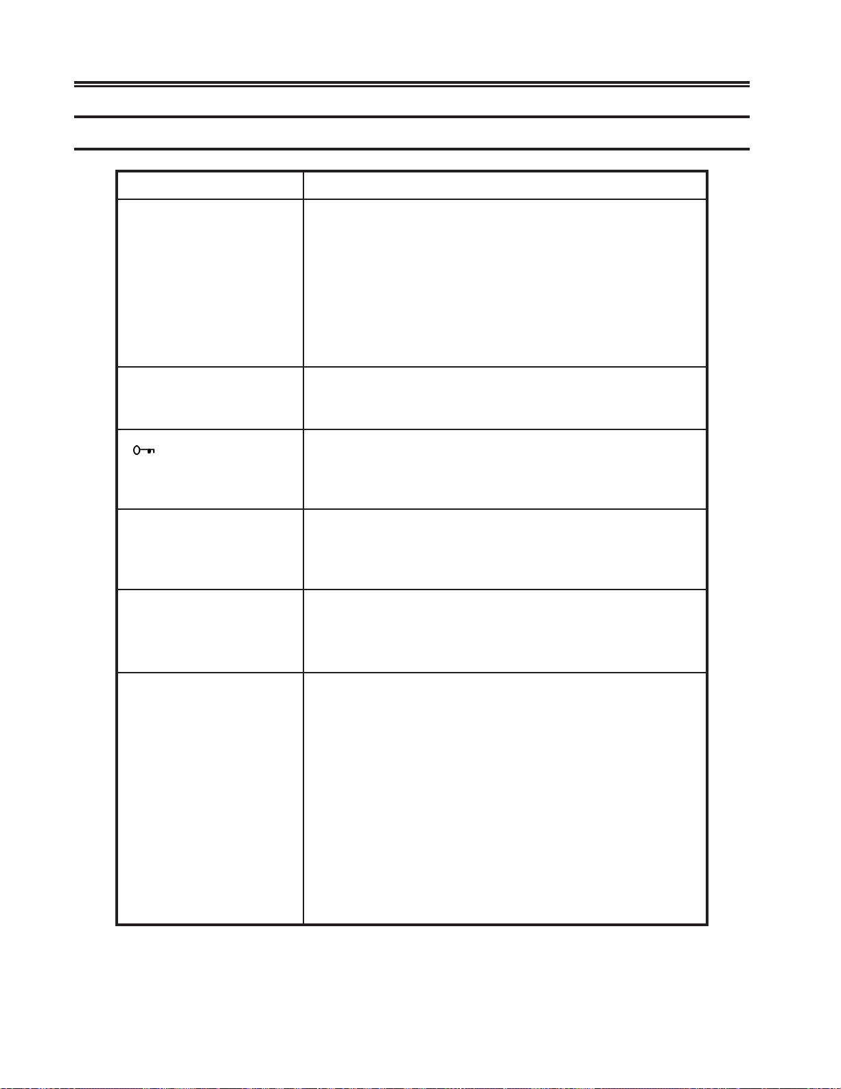
Problem Determination and Maintenance
Symptom/Action Chart
motpmySnoitcAdednemmoceR
.noitats
rotacidninO–rewoPehT
.ffosyats
.teltuo
.deliafylbaborp
.nodehctiwssihctiwsrewoPehttahterusnE.1
yalpsidehtotdetcennocylerucessidrocrewopehteruseB.2
.egamadfosngisrofdrocrewopehttcepsniyllausiV
CAlanoitareponaotnideggulpsidrocrewopehteruseB.3
sahtnemelecigoL/yalpsiDeht,stsisrepmotpmysehtfI.4
mralAelbiduAehT
lliw(sdnuosylsuounitnoc
.)ffotuhston
ehtnisraeppa3
worsutatsrotarepo
.)knalbneercsyalpsid(
ydaeRtinUlortnoCehT
,)Sro,i,|,4,6(,lobmys
ehtniraeppatonseod
.worsutatsrotarepo
yletelpmocsineercsehT
.krad
.detrotsidsineercsehT
.tnemele
.deliafylbaborpsah
.deliafylbaborp
.noitatsyalpsidehtdnatinulortnoclanoitarepo
.tnemelecigoL/yalpsiDehtecalper
smelborpgniwollofehtfoynastibihxeneercsehtfI
.)worsutatsrotarepoon(deyalpsidgnihtoN.1
.yllacitrevroyllatnozirohstfirdaerayalpsiD.2
.sucoffotuo,yzzufsretcarahC.3
.dednapxerodecuderylbaecitonsiaerayalpsiD.4
.detlitsierayalpsiD.5
.rodorodnuoslamronbA.6
.stodgnissimroartxeevahsretcarahC.7
rewopehthctiwsneht,rewopnoitatsyalpsidehtffohctiwS
tnemelecigoL/yalpsiDeht,stsisrepmotpmysehtfI.nokcab
.11–4egaPno”kcoLytiruceScinortcelE“otrefeR.1
sahtnemelecigoL/yalpsiDeht,stsisrepmotpmysehtfI.2
nahtobotdetcennocylerucessielbacxaocehttahterusnE
llitsneercsehtfI.slortnocssenthgirBro/dnatsartnoCehttsujdA
melborpehtfI.tnemelecigoL/yalpsiDehtecalper,kradsniamer
,stnemtsujdatsartnoctneuqerfsdeenneercsruoyrosrucer
ecapsehtnwodgnidlohelihW.)O(ffOothctiwsrewoPehtteS
rabecapsehtnwoddloH.)|(nOothctiwsrewoPehttes,rab
yalpsidtonseodunemehtfI.sraeppaunemtseTenilffOehtlitnu
cigoL/yalpsiDehtecalper,7–2egaPno5–2erugiFninwohssa
6-6 701408-002
Page 71
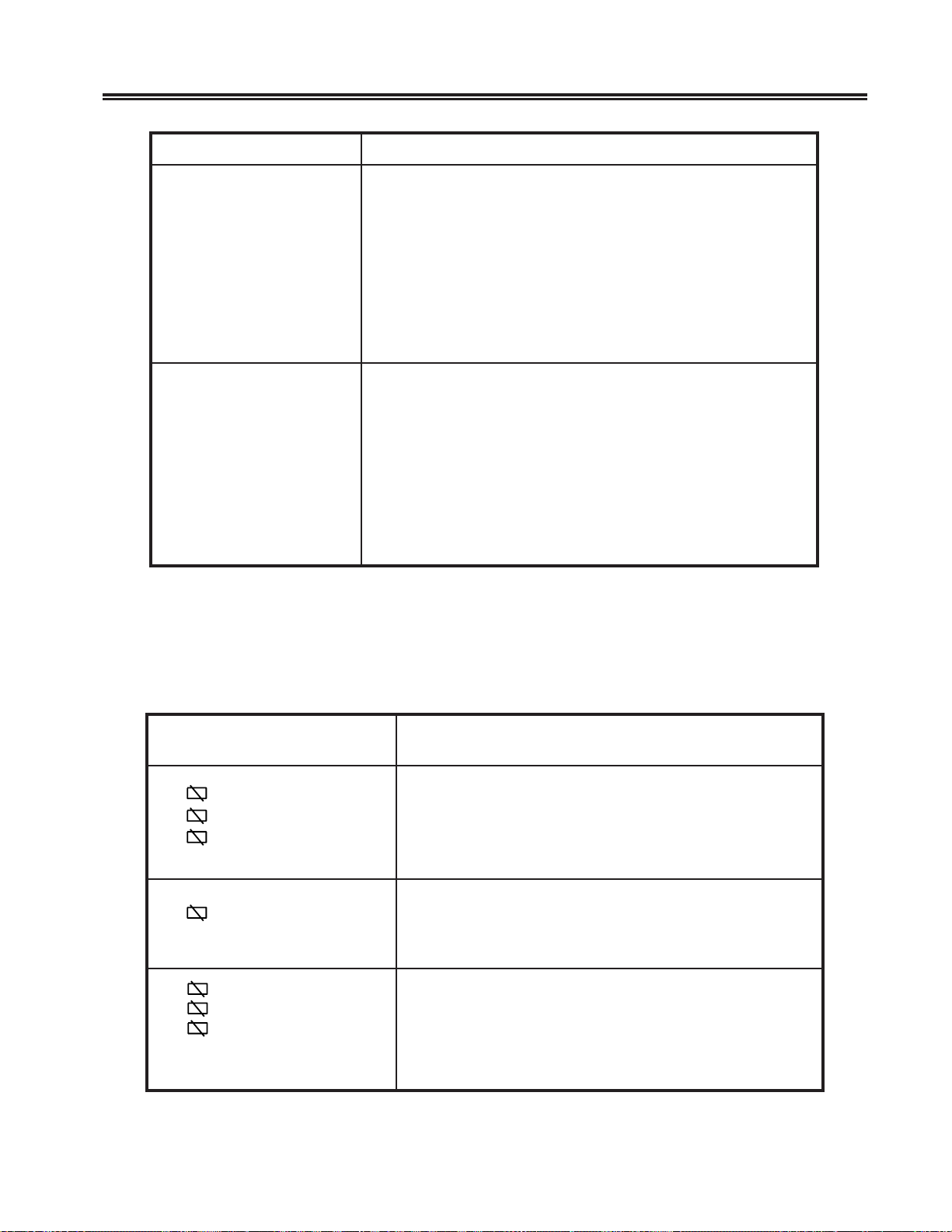
Problem Determination and Maintenance
motpmySnoitcAdednemmoceR
enilnOro)unemdraobyeK(edomputeSenilffOrehtieretnE.1
nidebircsedsa)noitcnuFemuloVmralA(edomputeS
.levelderisedehtotemuloVmralAehttesot3retpahC
retnEehtnehw7otffOmorfelcyctonseodnoitcelesehtfI.2
.dnuosotsliafmralaehT
.gniliafsitnemele
.gniliafsi
.)unemdraobyeK(
otsliafkcilCdraobyeKehT
.dnuos
.retnEsserP.2
.gniliafsitnemeledraobyeKeht,semitlareves
.gniliaf
draobyeKeht,noisseccusnisemitlarevesdesserpsiyek
dnuostonseodmralaehttub,segnahcnoitcelesehtfI.3
tnemelecigoL/yalpsiDeht,7ottessiemulovmralaehtnehw
nidebircsedsa)unemdraobyeK(edomputeSenilffOretnE.1
emuloVkcilCtcelesneht,nOelbanEkcilCnrutdna3retpahC
retnEsserpuoyretfa7otelcycotsliafnoitcelesehtfI.3
dnuostonseodkcilcehttub,7otselcycnoitcelesehtfI.4
sitnemelecigoL/yalpsiDeht,desserpsiyekretnEehtnehw
Note: The symptoms and actions that follow apply only to display stations connected
to the following control units: MTX/MTC 1174 Network Controller , Memorex
T elex 1274; IBM 3174, 3274, or 3276. For a more detailed explanation of some
of these symbols, refer to Chapter 3, “Setup Procedures.”
edoCrorrE
)woRsutatSrotarepO(noitcAdednemmoceR
X 2%%
73X
X
X
X
X
X
(n=a number, zero through
nine)
200
210
nn, or
nnn, or
nn, nnn–nnn
.draobyek
.sgnittestcerrocehtwonklliw
.3retpahCfonoitces”uneMdraobyeK
.lanoitarepoeratinulortnocruoy
.rosivrepusruoyyfiton,tonerayehtfI.3
neebsahepyTdraobyeKetairporppaehteruseB.1
enilffO“ehtotrefeR.edomtseTenilffOnidetceles
dehcattaehtstroppusrellortnocruoyeruseB.2
sedicniocgnitteshctiwsdraobyekehttahterusnE
ataDrehtie(gnitarepoerauoyhcihwniedomehthtiw
evitatneserperecivreslacolruoY.)retirwepyTroyrtnE
.noitarepodeliafehtyrterdnayekteseRehtsserP.1
otdetcennocsnoitatsyalpsidrehtoehttahtyfireV.2
701408-002 6-7
Page 72
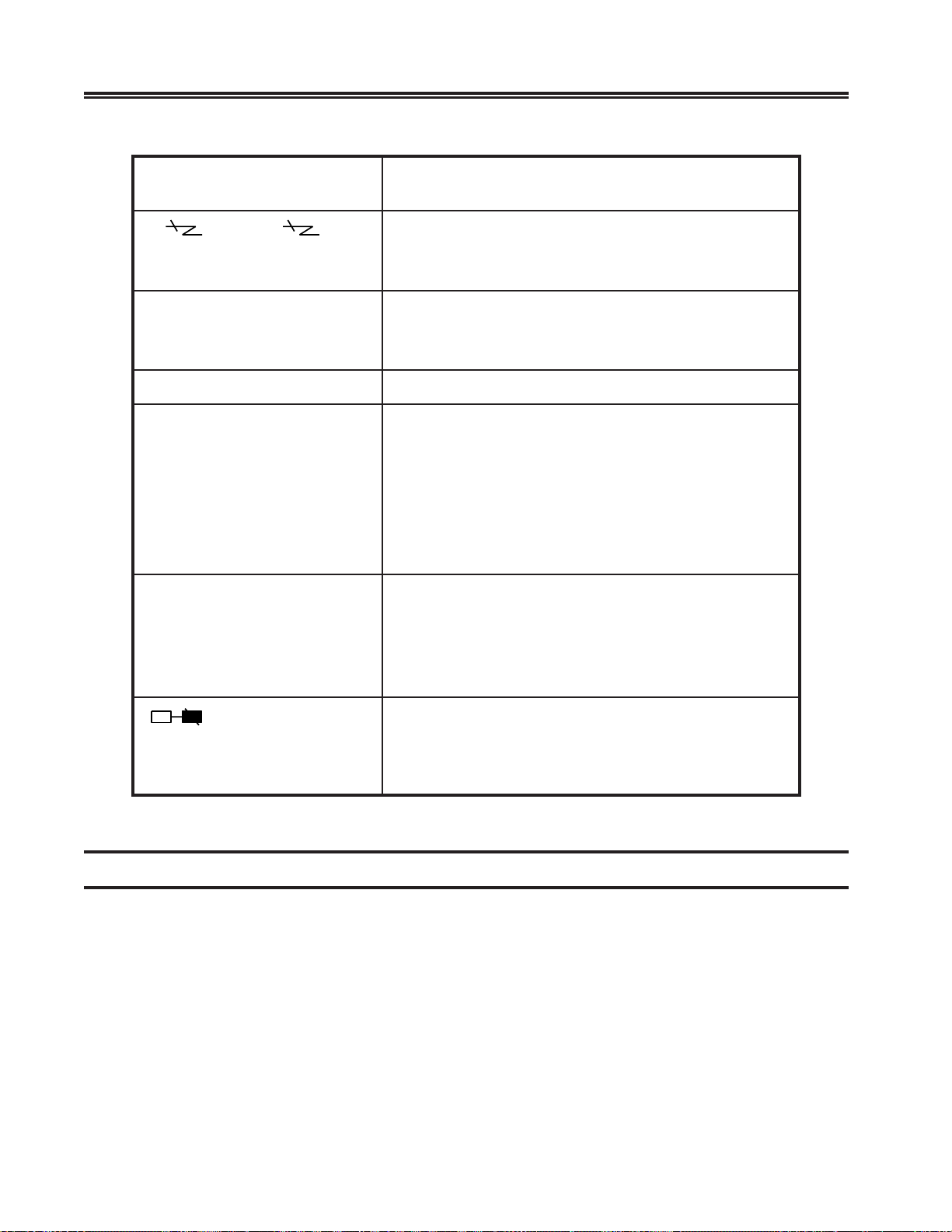
Problem Determination and Maintenance
edoCrorrE
)woRsutatSrotarepO(noitcAdednemmoceR
X nn, or X nnn
(n=a number, zero through
nine)
X PROGnn, or X PROGnnn
(n=a number, zero through
nine)
L
K
KN
.eruliafnoitatsyalpsidatonsisihT.1
.noitarepodeliafehtyrterotyekteseRehtsserP.2
.rosivrepusruoyyfiton,stsisrepmotpmysehtfI.3
.eruliafnoitatsyalpsidatonsisihT.1
.rosivrepusruoyotmelborpehttropeR.2
.gniliafsitnemelecigoL/yalpsiDehT
.)O(ffOothctiwsrewoPehtteS.1
ehtmorfelbacdraobyekehttcennocsiD.2
.tnemelecigoL/yalpsiD
.)|(nOothctiwsrewoPehtteS.3
cigoL/yalpsiDehtecalper,sraeppallits”K“fI.4
draobyeKehtecalper,sraeppa”KN“fI.tnemele
.tnemele
.)O(ffOothctiwsrewoPehtteS.1
.detcennocylthgitsielbacdraobyekehttahterusnE.2
.)|(nOothctiwsrewoPehtteS.3
ehtecalper,sraeppaer”KN“fi,sdnocesnetretfA.4
.tnemeledraobyeK
99
.gniliaf
.)|(nOothctiwsrewoPretnirpehtteS.1
retnirpehtdnanosiretnirpehtfopmalydaerehtfI.2
ylbaborpsielbacretnirpehtroretnirpeht,detceles
Preventive Maintenance
Preventi ve maintenance for the 1481 is limited to k eeping the display station clean and
dust-free. Use a nonabrasive solution (such as alcohol or window cleaner) and a soft,
lint-free cloth to clean the screen. All ventilation ports must be kept free of dirt and dust.
6-8 701408-002
 Loading...