

Page 1

FEP-4600
Installation and Configuration
P/N 707119-001
1
Page 2

Page 3

FEP-4600 Installation and Configuration
Revision Information
Issue/Revision Schedule
Comments Revision Number Date
Initial Release 707119-001 2/19/2009
707119-001 iii
iv 707119-001
Page 4

Page 5

FEP-4600 Installation and Configuration
Table of Contents
Revision Information ......................................................................................................... iii
Table of Contents.................................................................................................................v
Chapter 1. FEP-4600 Installation..................................................................................... 1-1
Product Overview ....................................................................................................... 1-1
Initial Installation........................................................................................................ 1-1
Chassis Installation ..................................................................................................... 1-2
Rack Installation ......................................................................................................... 1-3
Cabling the FEP-4600 for Power................................................................................ 1-5
Cabling for ESCON .................................................................................................... 1-5
Cabling for Serial Connections................................................................................... 1-5
Cabling for Ethernet.................................................................................................... 1-6
Cabling for Token Ring .............................................................................................. 1-6
Interconnecting Clustered FEP-4600 Platforms ......................................................... 1-7
Editing the FEP4600.ini File....................................................................................... 1-8
Powering up the FEP-4600 ......................................................................................... 1-9
Chapter 2. Configuration Overview................................................................................. 2-1
Initial Configuration of the FEP-4600 ........................................................................ 2-1
Initial Connection Panel......................................................................................... 2-2
Login Panel ............................................................................................................ 2-3
FEP-4600 Status Panel........................................................................................... 2-4
Making Configuration Updates.............................................................................. 2-6
Chapter 3. Management Interface.................................................................................... 3-1
Network Options Panel............................................................................................... 3-2
Field Definitions .................................................................................................... 3-2
Button Definitions.................................................................................................. 3-3
Configure Server Options ........................................................................................... 3-4
Display Red Status Options ................................................................................... 3-4
Status Screen Refresh Rate .................................................................................... 3-5
Kernal Debug Messages ........................................................................................ 3-5
Log Which Events.................................................................................................. 3-5
Log File Retention Policy ...................................................................................... 3-5
Email Alert Notification ........................................................................................ 3-6
Button Definitions.................................................................................................. 3-6
Change Password........................................................................................................ 3-7
Button Definitions.................................................................................................. 3-7
Connectivity Options .................................................................................................. 3-8
Clustering Panel.......................................................................................................... 3-8
Circuits Panel.............................................................................................................. 3-8
Save/Restore Configuration Panel .............................................................................. 3-9
Saving the Current Configuration........................................................................ 3-10
707119-001 v
Page 6

Deleting a Configuration...................................................................................... 3-10
Activating a Stored Configuration....................................................................... 3-11
Chapter 4. ESCON Interface............................................................................................ 4-1
Configure ESCON CUs Panel .................................................................................... 4-2
Field Definitions .................................................................................................... 4-2
Button Definitions.................................................................................................. 4-4
Other Panel Information ........................................................................................ 4-4
Configuring Subchannels for Protocol ‘SNA-PU2 (3174)’........................................ 4-5
Field Definitions .................................................................................................... 4-5
Button Definitions.................................................................................................. 4-6
Configuring Subchannels for Protocol ‘SNA-PU4 (SCTC)’...................................... 4-7
Field Definitions .................................................................................................... 4-8
Button Definitions.................................................................................................. 4-9
Configuring Subchannels for Protocol ‘XCA’ ......................................................... 4-10
Field Definitions .................................................................................................. 4-10
Button Definitions................................................................................................ 4-11
Configuring Subchannels for Protocol ‘NSNA (3174, 2701)’ .................................4-12
Field Definitions .................................................................................................. 4-12
Button Definitions................................................................................................ 4-13
Configuring Subchannels for Protocol ‘EP-BSC’ ....................................................4-14
Field Definitions .................................................................................................. 4-14
Button Definitions................................................................................................ 4-15
Deleting CU Panel ....................................................................................................4-16
Button Definitions................................................................................................ 4-16
Chapter 5. Token Ring Interface...................................................................................... 5-1
Token Ring Line Options............................................................................................ 5-3
Field Definitions .................................................................................................... 5-3
Button Definitions.................................................................................................. 5-5
Drop Panel Option Determination .............................................................................. 5-6
Static vs Dynamic Drops ....................................................................................... 5-6
SAP Assignments .................................................................................................. 5-6
Window Size Selection.......................................................................................... 5-7
Token Ring Drop Panel for Protocol ‘SNA-PU2’ ...................................................... 5-8
Field Definitions .................................................................................................... 5-8
Button Definitions................................................................................................ 5-10
Token Ring Drop Panel for Protocol ‘XCA’ ............................................................ 5-11
Field Definitions .................................................................................................. 5-11
Button Definitions................................................................................................ 5-12
PU 4 Interface Options.............................................................................................. 5-13
Token Ring Drop Panel for Protocol ‘SNA-PU4’ .................................................... 5-13
Field Definitions .................................................................................................. 5-14
Button Definitions................................................................................................ 5-15
Deleting Token Ring Drops Panel ............................................................................ 5-16
Button Descriptions ............................................................................................. 5-16
vi 707119-001
Page 7

FEP-4600 Installation and Configuration
Chapter 6. Ethernet Interface ........................................................................................... 6-1
Ethernet Line Options ................................................................................................. 6-3
Field Definitions .................................................................................................... 6-3
Button Definitions.................................................................................................. 6-5
Bit-Swapping LAN Addresses.................................................................................... 6-6
Ethernet Drop Panel for Protocol ‘SNA-PU2’............................................................ 6-7
Field Definitions .................................................................................................... 6-7
Button Definitions.................................................................................................. 6-9
Ethernet Drop Panel for Protocol ‘XCA’.................................................................. 6-10
Field Definitions .................................................................................................. 6-10
Button Definitions................................................................................................ 6-11
PU4 Interface Options............................................................................................... 6-12
Ethernet Drop Panel for Protocol ‘SNA-PU4’.......................................................... 6-13
Field Definitions .................................................................................................. 6-13
Button Definitions................................................................................................ 6-14
Deleting Ethernet Drops ........................................................................................... 6-15
Button Descriptions ............................................................................................. 6-15
Chapter 7. SDLC Interface .............................................................................................. 7-1
Configure SDLC Line Options ................................................................................... 7-3
Field Definitions .................................................................................................... 7-3
IDBLK and IDNUM Usage................................................................................... 7-5
Button Definitions.................................................................................................. 7-5
SDLC Drop Panel (PU Type 2) .................................................................................. 7-6
Field Definitions .................................................................................................... 7-6
Button Definitions.................................................................................................. 7-7
SDLC Drop Panel (PU Type 4) .................................................................................. 7-8
Field Definitions .................................................................................................... 7-8
Button Definitions.................................................................................................. 7-9
Deleting SDLC Drops Panel..................................................................................... 7-10
Button Definitions................................................................................................ 7-10
Chapter 8. 3270 Bisync Interface..................................................................................... 8-1
Configuring Bisync Line Options............................................................................... 8-3
Field Definitions .................................................................................................... 8-3
Button Definitions.................................................................................................. 8-5
Bisync Drop Panel ...................................................................................................... 8-6
Field Definitions .................................................................................................... 8-6
IBM Control Codes for Bisync Addressing........................................................... 8-7
Button Definitions.................................................................................................. 8-7
Deleting Bisync Drops................................................................................................ 8-8
Button Definitions.................................................................................................. 8-8
Chapter 9. Clustering ....................................................................................................... 9-1
Clustering Overview ................................................................................................... 9-1
707119-001 vii
Page 8

Configuring the Clustering Feature ............................................................................ 9-1
Removing a member from a Cluster........................................................................... 9-4
Chapter 10. PU4 SNI Over IP........................................................................................ 10-1
Field Definitions ....................................................................................................... 10-2
Button Definitions..................................................................................................... 10-3
Chapter 11. Static Gateway Circuits.............................................................................. 11-1
Configuring Static Gateway Circuits........................................................................ 11-1
Configure Static Circuits Panel................................................................................. 11-2
Drop Down Control Definitions ............................................................................... 11-3
Button Definitions..................................................................................................... 11-3
viii 707119-001
Page 9

FEP-4600 Installation and Configuration
Chapter 1. FEP-4600 Installation
This chapter covers procedures needed to position the FEP-4600 such that it is ready to
be configured.
Product Overview
The FEP-4600 is a versatile 3U, rack-mountable enterprise class server gateway product
capable of running many features and functions traditionally supported on the IBM 37x5
Front End Processor product family. Each FEP-4600 platform is capable of being
populated with a combination of up to five interface cards, targeted to achieving that
goal. Multiple FEP-4600 platforms may be interconnected via high speed (Gigabit)
Ethernet, to provide the means to accommodate larger, more complex environments.
Configuration of the FEP-4600 is achieved by means of a secure web browser interface
(HTTPS). The FEP-4600 ships with a default configuration including a default IP
address. You must modify the configuration for your own network requirements. The IP
interface can be modified by editing or creating a text file (FEP4600.ini) located on a
3.5” floppy (supplied with the base unit) using a PC, and inserting this file into the floppy
drive of the FEP-4600, prior to booting.
Once configured, the FEP-4600 is capable of running independently, without human
intervention. That is, if power is lost and regained, it will automatically boot back into
service using the stored configuration. You can manage the platform using the same
secure web browser connection from anywhere. Multiple console interfaces are supported
by the FEP-4600, making it ideal for remote disaster recovery operations.
When interconnected (clustered), multiple FEP-4600s can be configured as if they were a
single unit. FEP-4600 platforms may be interconnected between remote sites, provided
that the communication between the platforms is of sufficient bandwidth. The
communications between platforms utilizes a secure IP connection.
Initial Installation
Installation of the FEP-4600 consists of multiple steps, and may involve more than one
person. Tasks required to complete an installation include:
1. Mounting the hardware platform (if desired) in a rack or placing the platform
within the necessary proximity of all of the network connections required to
satisfy the configuration.
2. Cabling the unit for power, ESCON, Ethernet, Token Ring, and Serial
connections as needed.
3. Editing the FEP4600.ini file if necessary to provide access to a web browser
capable platform, such as a PC.
4. Powering up the unit with the floppy containing the FEP4600.ini file.
707119-001 1-1
Page 10

Chapter 1. Installation
5. Connect to the platform with a web browser to finish the configuration.
If multiple FEP-4600 platforms are to be interconnected, you may elect to bring them up
one at a time, or through editing of the FEP4600.ini file on each platform, bring them up
as a group. Gateway circuits requiring an ESCON half-circuit on one platform and a
downstream connection on another platform require that both units are powered up and
communicating with each other to make the configuration.
Chassis Installation
Tools needed:
1. Phillips Screw Driver
2. Antistatic Strap
Installing Chassis Rails:
Please make sure that the chassis covers and chassis rails are installed on the chassis
before you install the chassis into the rack.
To avoid personal injury and property damage, please follow all the safety steps listed
below.
Before installing the chassis rails:
1. Enclose the chassis with chassis covers.
2. Unplug the AC power cord(s).
3. Remove all external devices and connectors.
Procedures to install chassis rails:
1. Included in the shipping package is a pair of rail assemblies. In each rail
assembly, locate the inner rail and the outer rail.
2. Press the locking tab to release the inner rail from its locking position and pull out
the inner rail from the rail assembly. (The inner rails are to be attached to the
chassis and the outer rails are to be installed in the rack.)
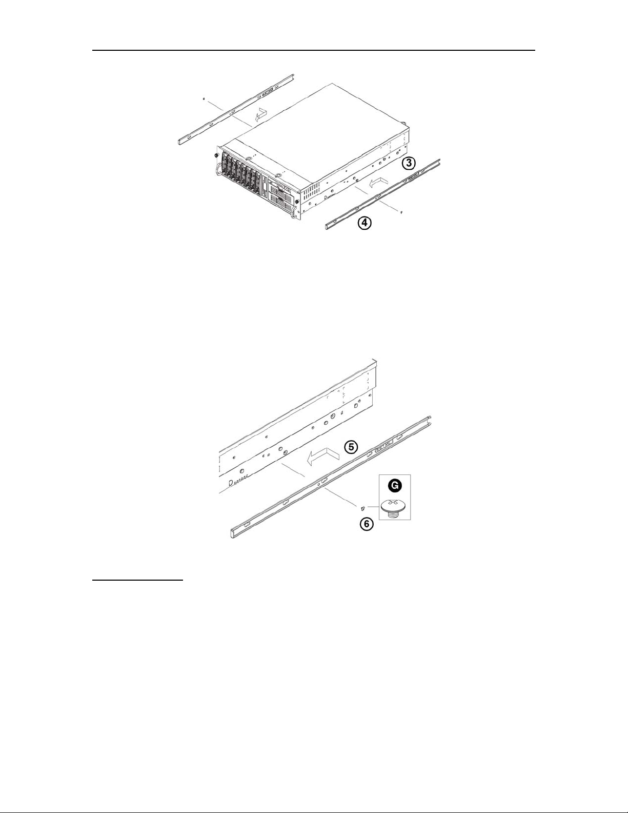
3. Locate the five rail buttons and each side of the chassis and locate the five
corresponding holes on each of the inners rails.
(Please note that one end of the hole is larger than the other end of the hole.)
1-2 707119-001
Page 11
FEP-4600 Installation and Configuration
4. Align the larger end of each hole against its corresponding button. Once all
aligned, push the holes toward their corresponding buttons and the rail is placed
on the chassis.
5. Once the rail is placed on the chassis, pull the rail forward until the rail buttons
lock in the small ends of the corresponding holes.
6. Secure the rail to the chassis with a Type G screw. Repeat the above steps to
install the other rail on the chassis.
Rack Installation
After you have installed the inner rails on the chassis, you are ready to install the outer
rails of the rail assemblies to the rack.
(The rails are designed to fit in the racks with the depth of 28-33”.)
Procedure:
1. In the package, locate a pair of front (short) and rear (long) brackets. Please note
that the brackets are marked with Up/Front Arrows (front) and Up/Rear arrows
(rear).
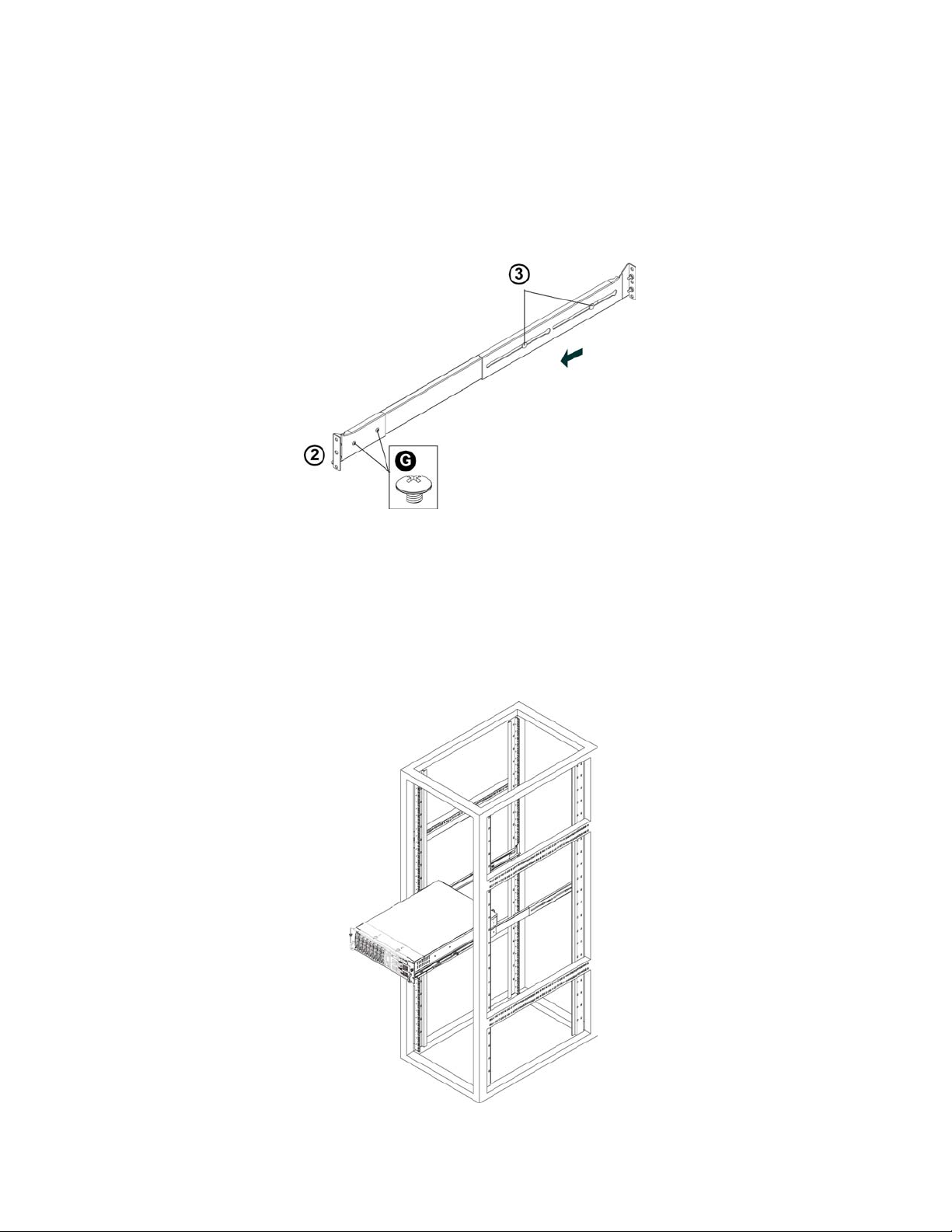
2. Secure the front (short) bracket (marked with the Up/Front arrows) to the outer
rail with two Type G screws.
707119-001 1-3
Page 12
Chapter 1. Installation
3. Locate the two buttons on the outer rail and attach the rear (long) bracket to it by
sliding the opening of the rear rail through the button.
4. Measure the depth of your rack and adjust the length of the rails accordingly.
5. Repeat the same steps to install the other outer rail on the chassis.
6. Secure both outer rail assemblies to the rack with Type H screws and Type I
washers.
7. Slide the server chassis into the rack from the front.
(The server may not slide into the rack smoothly or easily when installed the first
time. Some adjustments to the slide assemblies might be needed for easy
installation.)
8. You will need to release the safety taps on both sides of the chassis in order to
completely remove the chassis out of the rack.
1-4 707119-001
Page 13
FEP-4600 Installation and Configuration
Cabling the FEP-4600 for Power
The FEP-4600 supports a total of 3 hot-swappable power supplies. Each power supply
requires a separate power cord. Each power supply can be plugged into a separate power
source if available. Each power source should be properly grounded.
Cabling for ESCON
The ESCON interface cards used by the FEP-4600 use a duplex ESCON interface cable.
Each ESCON interface card ships with a plastic plug inserted into the ESCON interface,
for purposes of keeping dust from the optical leads and to help protect the connector
during shipment. The plastic plugs should be left in place until you are ready to attach the
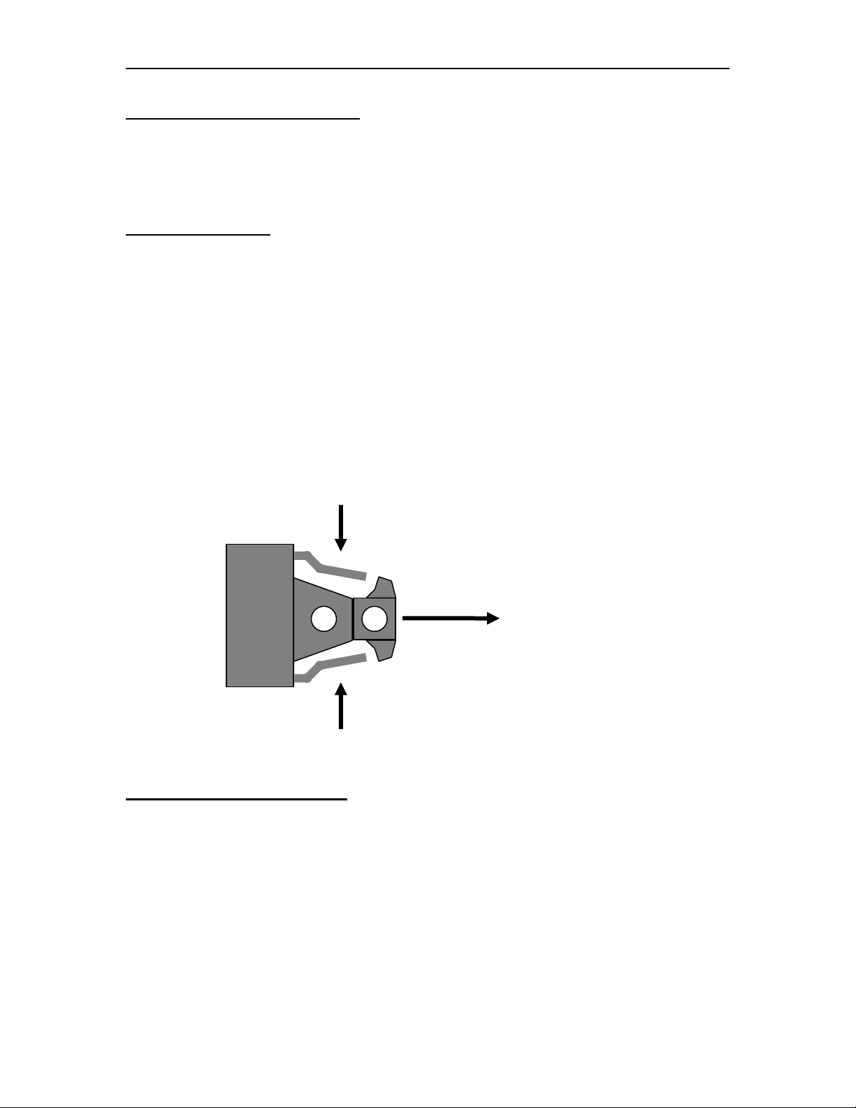
ESCON cables. When ready, squeeze the sides of the plastic plug to disengage it and
allow it to be removed, as diagrammed below. (You may want to set these plugs aside in
a safe place for future use.) Insert the ESCON cable into the cavity vacated by the plastic
plug, and push in until you hear/feel it click into place. Be careful when handling ESCON
cables, and do not bend the cables any more than necessary. The cables are fiber optics,
and bending them too tightly will cause them to break internally, and make them useless.
Squeeze
Extract
Squeeze
Cabling for Serial Connections
Each QSI (SDLC/X.25), QSA (SDLC/X.25) or QBA (BSC) card utilizes a “Hydra” cable
implementation (QSI and QSA cards use a single Hydra cable with four modem ends and
QBA cards use a pair of Hydra cables with two modem ends each). The single connector
end of the Hydra cable is attached to the back of the QSI, QSA or QBA card. Connectors
located at the multi-connector end, will be connected to modem cables or modem
eliminator cables depending on the type of interface purchased. Hydra cables are
approximately 6 ft. in length.
707119-001 1-5
Page 14

Chapter 1. Installation
Cabling for Ethernet
The Ethernet interfaces for the FEP-4600 each consist of an RJ45 socket. Plug a standard
Ethernet cable with an RJ45 jack mounted on the end, into the appropriate socket until
you feel it click into place. The Ethernet interface of the FEP-4600 will default to autodetect the speed and can be plugged into a switch or hub running at 10 Mhz, 100 Mhz, or
1000 Mhz. Note that the interface may be reconfigured to operate at a specific speed in
the configuration.
Ethernet Cable Spec
Category 3, 4, or 5 ANSI/IEEE Standard
Maximum Length 100 meters (328 feet) 802.3I – 1990 Section 14 or greater
Minimum Length 1 meter (3.28 feet)
Recommended Minimum Cabling Type
Ethernet Speed Minimum Twisted Pair Cable Type
10 Mbps Cat 3
100 Mbps Cat 5
1000 Mbps Cat 5e
Cabling for Token Ring
The Token Ring interfaces for the FEP-4600 each support both, RJ45 and 9-pin D
sockets. RJ45 connectors should be inserted until you feel it click into place. 9-pin D
connectors should be secured with captive screws. The Token Ring interface of the FEP4600 defaults to auto-detect the speed and can be plugged into a switch or a hub running
at 4 Mhz, 16 Mhz, or 100 Mhz. Note that the interface can be reconfigured to run at a
specific speed if desired.
Recommended Minimum Cabling Type
Token Ring Speed Minimum Twisted Pair Cable Type
4 Mbps Cat 2
16 Mbps Cat 3
100 Mbps Cat 5
1-6 707119-001
Page 15

FEP-4600 Installation and Configuration
Interconnecting Clustered FEP-4600 Platforms
If your installation includes multiple FEP-4600 platforms clustered together to function
as a single unit, you must provide a pathway for them to communicate with each other.
This is accomplished by providing an Ethernet connection for them to talk over. It is
strongly suggested that the Ethernet connection used to interconnect the platforms be
over dedicated connections (not the corporate LAN).
To communicate together, each unit must have an IP address assigned that is unique. It is
not necessary to configure a default gateway for the interconnection if the LAN is
dedicated unless it must cross to a different subnet. Reference the ‘Editing the
FEP4600.INI File’ section below for assigning IP addresses initially for each of these
units.
If you only have two FEP-4600 platforms, you can run a crossover cable between the two
units. Otherwise, you will need a hub or switch to connect each of the FEP-4600
platforms into to provide the intra-cluster communication.
It is recommended to use the fastest connection available to interconnect the platforms.
The interface will run at 1 Gbps, 100 Mbps, and 10 Mbps. 1 Gbps connections may not
be practical when interconnecting platforms at physically different locations. Refer to the
Ethernet cabling specs for recommended cabling types.
707119-001 1-7
Page 16

Chapter 1. Installation
Editing the FEP4600.INI File
The FEP-4600 ships with a default IP address of 192.168.0.46. You can use this address
as is, providing that you connect to the platform with a PC configured for a compatible
address using a crossover cable or an appropriate hub. However, if you prefer to connect
the FEP-4600 to your existing IP network and assign it a different IP address, you can
override the existing IP address by editing the FEP4600.ini file found on the floppy that
is included with the FEP-4600 when it ships. If the original diskette that ships with the
product cannot be located, the file may be created with the entries as shown below, and
saved to a floppy using the FEP4600.ini file name.
[Network]
IP=192.168.0.46
NetMask=255.255.255.0
DefaultGateway=192.168.0.254
Notes regarding FEP4600.ini file entries:
1. No white space is allowed within the entries (spaces or tabs).
2. The data is not case sensitive.
3. The diskette is not required for future reboots (once an IP address has been
configured and saved) and should be removed after the initial load.
4. If the diskette is in the drive when the FEP-4600 is powered up in the future,
the values within the file will override any settings saved on the hard drive.
5. Obviously, select values that are compatible with your network, and
specifically the device that will be used to configure your platform.
1-8 707119-001
Page 17
FEP-4600 Installation and Configuration
Powering Up the FEP-4600
If you are applying an IP address, insert the floppy with the FEP4600.ini file into the
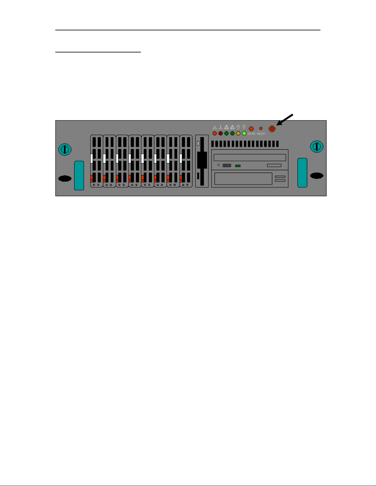
floppy drive before applying power. With one or more power cables attached to the FEP4600 and a power source, press the power button (button is located in the upper right
corner of the front of the platform) to apply power.
Power Button
If none of the indicators light up with the power applied, recheck the power cable
connections and check any power switches or circuit breakers associated with your power
source.
Once the power up sequence has completed (should take less than 5 minutes), you should
be ready to configure the FEP-4600 with your browser.
707119-001 1-9
Page 18

Chapter 1. Installation
1-10 707119-001
Page 19

FEP-4600 Installation and Configuration
Chapter 2. Configuration Overview
The configuration for the FEP-4600 is stored on the hard drive in the file FEP4600.ini. A
default file is loaded on in the factory. You will need to perform a configuration to
customize the FEP-4600 for your environment. Once configured, you should keep a
backup of your configuration in a safe place. You may use the Visara eManager product
to retrieve backups of your FEP-4600 automatically.
Configuration of the Visara FEP-4600 platform is accomplished through a secure
browser interface (HTTPS). Note that the browser that you use should be capable of
establishing an HTTPS connection. Each FEP-4600 ships from the factory preconfigured
for the IP address of 192.168.0.46. You may use this address or define a different address
by editing the FEP4600.ini file included on the diskette that shipped with the FEP-4600.
Refer to the previous chapter if you need to change the IP address.
You may override the configuration stored on the hard drive by inserting a floppy
containing a copy of the FEP4600.ini file, and forcing a boot of the platform.
The configuration of your FEP-4600 is password protected. If you forget your password,
you may work around the problem by using the original floppy which ships with the
platform. It has the default administrative password (‘admin’) configured (and
encrypted). Just insert the floppy and reboot. Do not attempt to edit the password in the
FEP4600.ini file to make a change. Because it is encrypted, typing anything in its place
will change the password to something unknown. If you have forgotten your password
and have also misplaced your floppy, contact your Visara representative.
Initial Configuration of the FEP-4600
You can perform the initial configuration of your FEP-4600 by attaching a monitor,
keyboard and mouse directly to the FEP-4600. You may also connect a PC directly to the
FEP-4600 by using a crossover Ethernet cable connected directly between the Ethernet 0
interface (leftmost Ethernet as looking from the rear) and your PC. You may also connect
the FEP-4600 directly to a hub or switch and connect your PC to the same hub or switch.
When connecting to the FEP-4600 using the default IP address, your PC must be
configured with an appropriate IP address to be able to communicate on the same subnet
as the FEP-4600 (192.168.0.x, where x= 1-254, but do not use ‘46’ which is used by the
FEP-4600, or ‘254’ which is already defined as the default gateway in the file).
If you are using the directly attached monitor, keyboard, and mouse, you may open the
local browser by using the mouse to select Start>Programs>Firefox. Firefox is the
browser that is included on the FEP-4600.
707119-001 2-1
Page 20
Chapter 2. Configuration Overview
If you are using a PC, once you have an appropriate hardware connection between your
PC and the FEP-4600, start your browser and connect to the configured IP address. (i.e.
‘http://192.168.0.46’)
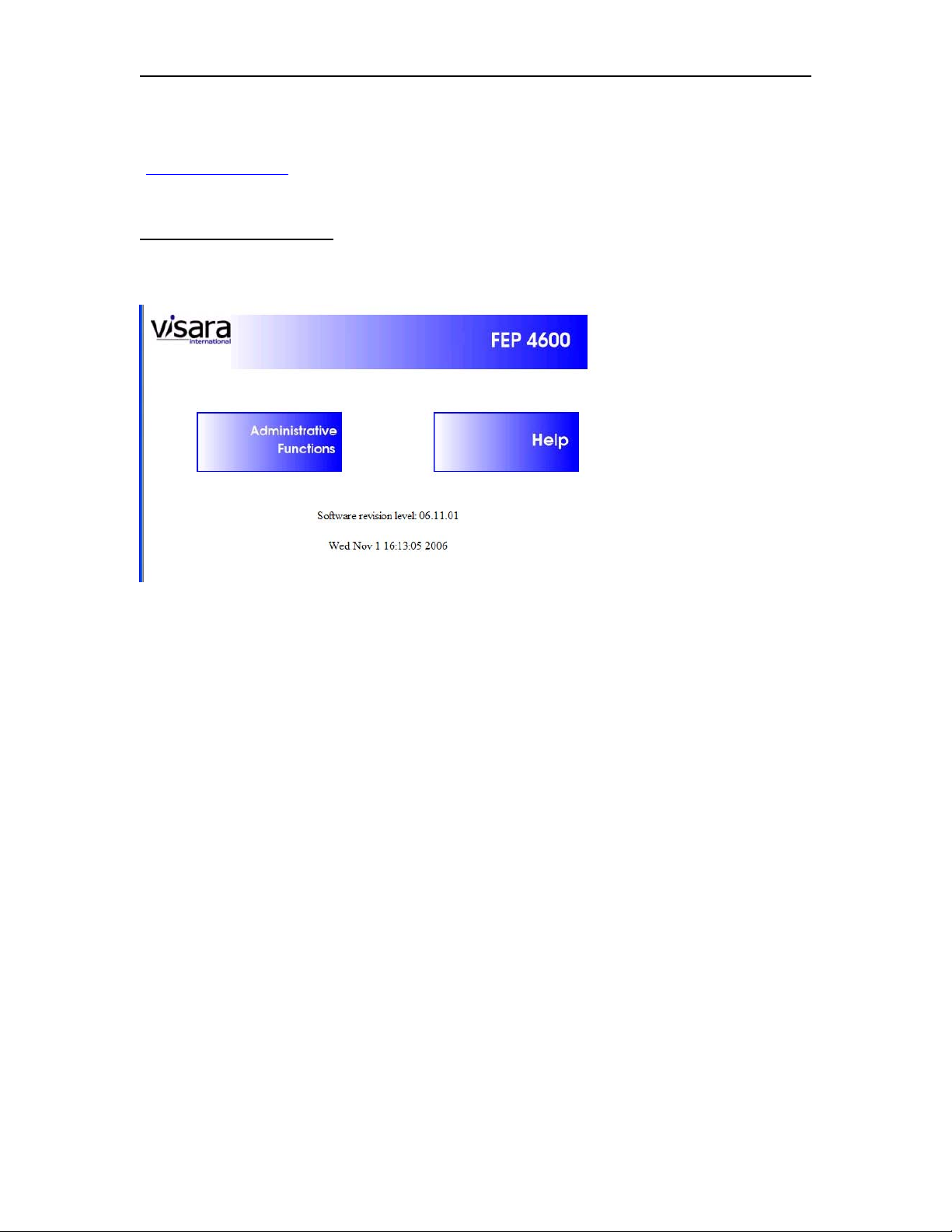
Initial Connection Panel
The initial connection should appear similar to the diagram below.
2-2 707119-001
Page 21
FEP-4600 Installation and Configuration
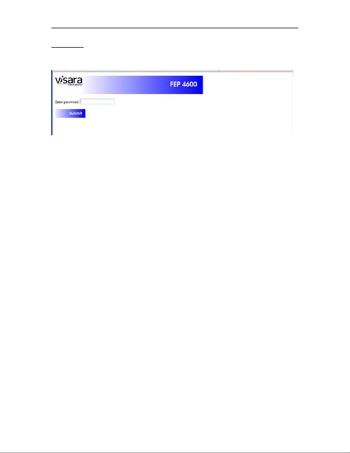
Login Panel
Select the administrative functions button. The following panel should appear.
Note that you may get a security alert when you attempt to proceed to get the Password
prompt. This is due to the secure SSL browser connection and the Visara self-signed
certificate.
If you do not wish to see this warning each time that you establish a connection, you can
normally view and install the certificate on the PC or thin client platform that you are
using the browser from.
707119-001 2-3
Page 22
Chapter 2. Configuration Overview
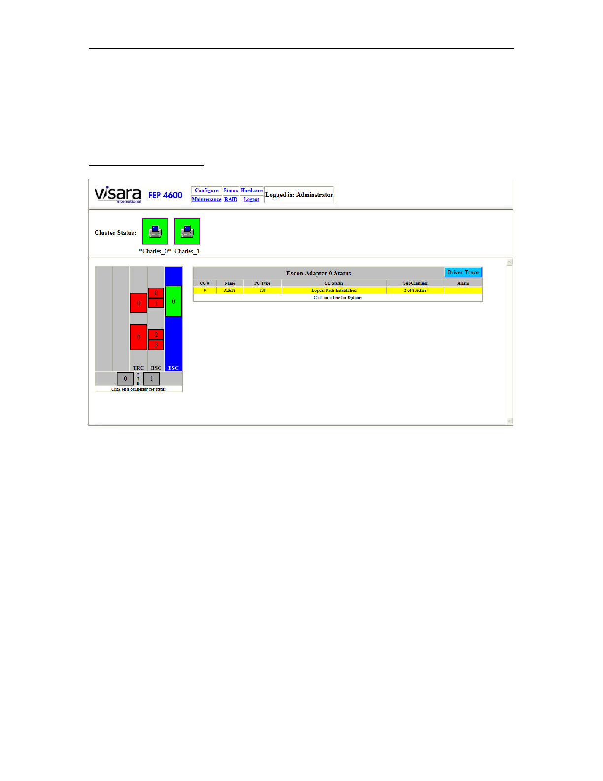
Enter the default administrator password (‘admin’) to continue. The next panel to appear
is the Status panel, and will appear similar to the one shown below. The actual diagram
on the left however will vary, depending on the hardware composition of your FEP-4600.
The tables on the right will also vary depending on what you have configured. Initially,
most everything will appear in the table as ‘Unconfigured’.
FEP-4600 Status Panel
Along the top of the panel, are several menu items:
• Configure
• Status
• Hardware
• Maintenance
• RAID
• Logout
You will also see the level of user that you are logged in as. Note that you can only
change the configuration if you are logged in as the ‘administrator’.
Directly below the menu and separated by a line, you may see two or more block icons
and the words Cluster Status. This section is only displayed if your unit is configured a
member of a cluster. Otherwise this section will not be present.
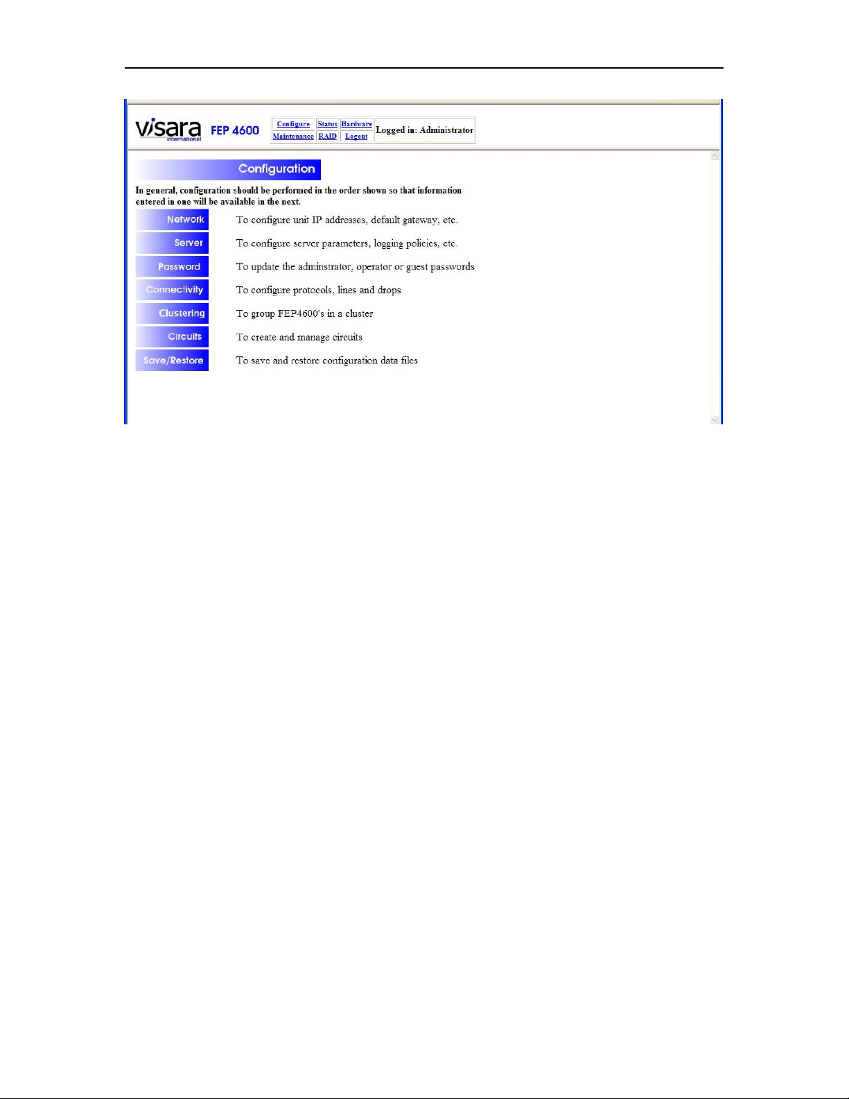
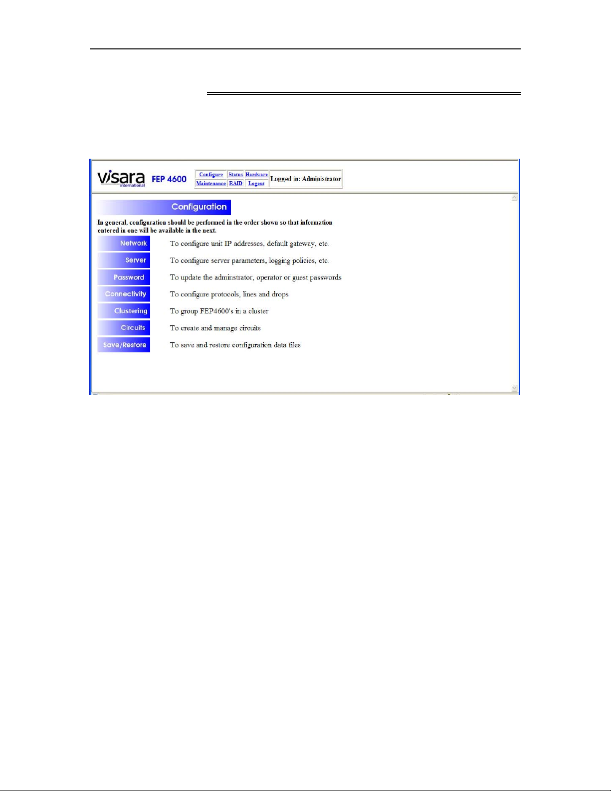
The configuration of the FEP-4600 can be accessed by selecting the ‘Configuration’
menu option at the top of the panel. The following panel should appear:
2-4 707119-001
Page 23
FEP-4600 Installation and Configuration
The configuration of the FEP-4600 can be broken down into two categories.
• Administrative configuration items
• Communications configurations (‘Connectivity’) items
Administrative configuration items include:
• Network options for management access
• Server options for passwords
• Logging options
• Managing of multiple configuration files
Communications configuration items include:
• Configuring all of the host communication options
• Configuring all of the static and dynamic downstream device communication
options
• Configure clustering if more than one FEP-4600 platform are to provide the
communication interfaces
• Configuring the Static Gateway Circuits that tie the host connections to the static
downstream devices
When Clustering more than one FEP-4600 together, you will need to establish the cluster
(and have all cluster members communicating with each other) before attempting to
create the Static Gateway Circuits. For the best results, it is recommended that you
perform the Communications portion of the configuration in the order shown above.
707119-001 2-5
Page 24

Chapter 2. Configuration Overview
Making Configuration Updates
It should be noted that most of the configuration panels have an ‘Update’ or ‘Submit’
button on them. These are used to save the changes. Changing values on a panel, then
closing the panel (by selecting the X in the upper right corner of the window or by
pressing the Return button, without pressing the Update button first, will not save your
changes, and any modifications will be lost.
2-6 707119-001
Page 25
FEP-4600 Installation and Configuration
Chapter 3. Management Interface
Selecting the Configuration option from the menu will result in a panel similar to what is
displayed below.
707119-001 3-1
Page 26
Chapter 3. Management Interface
Network Options Panel
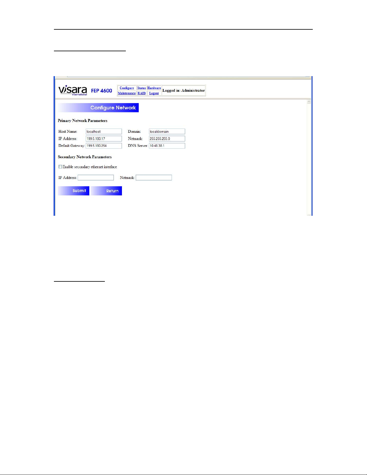
Selecting the ‘Network’ option will display the following configuration options:
The configuration options on this panel will allow you to modify the network interface
used for management of the FEP-4600. After you have entered all of the values that you
need, then press the ‘Submit’ button. The new values will be stored and will take affect
the next time the FEP-4600 gets booted.
Field Definitions
Primary Network Parameters:
Host Name: This is the name that this platform will identify itself with to SNMP or to a
DNS server. The value of this field defaults to ‘localhost’.
IP Address: Enter the IP address that you want to use with Ethernet interface 0.
Changing this value will affect the server IP address that you will browse, to make future
configuration changes.
Netmask: This is the subnet mask that is to be used by the Ethernet interface 0.
Default Gateway: This IP address is for the local router, which will interface the
FEP-4600 to the greater network. The FEP-4600 requires for you to fill in this field. If
you elect to keep the FEP-4600 connected to an isolated LAN, you will still need to
provide an unused address on the subnet to which the FEP-4600 will be attached.
Otherwise, enter the value for your local router. The FEP-4600 will automatically attempt
to route traffic through the default gateway whenever the destination is not on the local
3-2 707119-001
Page 27

FEP-4600 Installation and Configuration
subnet(s). When the secondary network interface is defined, the FEP-4600 will determine
whether the destination can be reached through either of the configured local subnets, and
will only use the default gateway if the destination is not reachable otherwise.
Domain: This is the default DNS domain that the FEP-4600 will be associated with.
DNS Server: The function of the DNS server is to allow you to use domain names
instead of IP addresses. Enter the value for your local DNS server if you are not to be on
an isolated network. Otherwise you may leave this value blank. Note that if you wish to
allow the FEP-4600 to update its code directly from the Visara FTP site, you will need to
configure DNS.
Enable Secondary Ethernet Interface Checkbox: If you need to use the second
Ethernet interface (Ethernet 1), then you will need to check this box.
Secondary Network Parameters:
IP Address: Enter the IP address that you want the ETH1 interface to use.
Netmask: Enter the subnet mask that you want the ETH1 interface to use.
Button Definitions
Submit: Saves the current information into the FEP4600.ini file for use on the next boot
of the platform.
Return: Returns back to the Configuration Menu panel.
707119-001 3-3
Page 28
Chapter 3. Management Interface
Configure Server Options
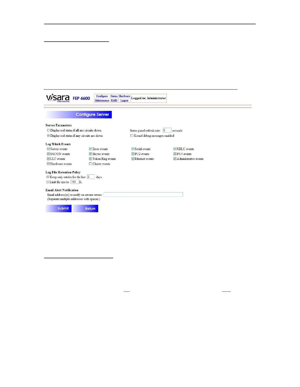
Selecting the ‘Server’ option from the Configuration panel brings up another panel for
configuring the Logging policies to be used by the FEP-4600. This panel appears below.
Information on viewing the file can be found in the FEP-4600 Users Guide and
Maintenance Manual (P/N 707118-00x). Information on interpreting the Log File can be
found in the FEP-4600 Problem Determination Manual (P/N 707120-00x).
Configurable options on this panel include:
Display Red Status Options
Status on the FEP-4600 is displayed in a hierarchical fashion. For example on SDLC,
there is a line status to give the overall status of the line. If you drill down on the line
(click the line status) you can see the status of all of the drops on the line. Two options
are offered for when the high order status is to be displayed with the color red. You can
define red to be used either when all lower order circuits are down or when any lower
order circuits are down.
3-4 707119-001
Page 29

FEP-4600 Installation and Configuration
Status Panel Refresh Rate
In order to provide updated status information, the browser interface status panels are
updated through a refresh initiated from the browser window automatically, any time that
status is being viewed. Because of the nature of a browser interface, when the status
information is refreshed, some displayed information may be reset to an initial format at
upon each refresh. The refresh rate (how often the status information is updated) is
determined by the setting on this panel. The default value for this refresh is set at 5
seconds.
Kernal Debug Messages
Kernal debug messages can be useful to help diagnose software problems that may arise.
Having debug messages enabled can possibly impact performance. The option of whether
to generate debug messages or not is a configurable item. Normally you would run
without Kernal debug messages in a production environment, and only enable them if
you are having a problem and under the direction of Visara support personnel.
Log Which Events
• Server Events
• ESCON Events
• LLC Events
• Hardware Events
• Error Events
• Bisync Events
• Token Ring Events
• Cluster Events
• Serial Events
• PU2 Events
• Ethernet Events
• SDLC Events
• PU4 Events
• Administrative Events
Log File Retention Policy
There are two options for limiting the size of the Log File. These are:
• Limit the size by limiting the number of days that the log includes. Old log entries
are purged automatically when they fall outside the prescribed timeframe.
• Limit the actual file size by setting the maximum file size that will be kept. As
new items are logged, the file size is monitored and old events will be dropped to
maintain the maximum file size.
707119-001 3-5
Page 30

Chapter 3. Management Interface
Email Alert Notification
Certain severe log events can generate an email message to be sent to one or more email
accounts. Enter the destination email address(es) where those messages are to be sent.
Multiple email addresses can be entered by leaving a space between each email address.
At this time you cannot configure which events are considered to be severe. Automatic
generation of severe event email messages and the sending of those messages is an
optional event determined by whether any email destinations have been generated.
Button Definitions
Submit: The Submit button saves the changes. These changes should take affect
immediately.
Return: The Return button takes you back to the previous panel.
3-6 707119-001
Page 31
FEP-4600 Installation and Configuration
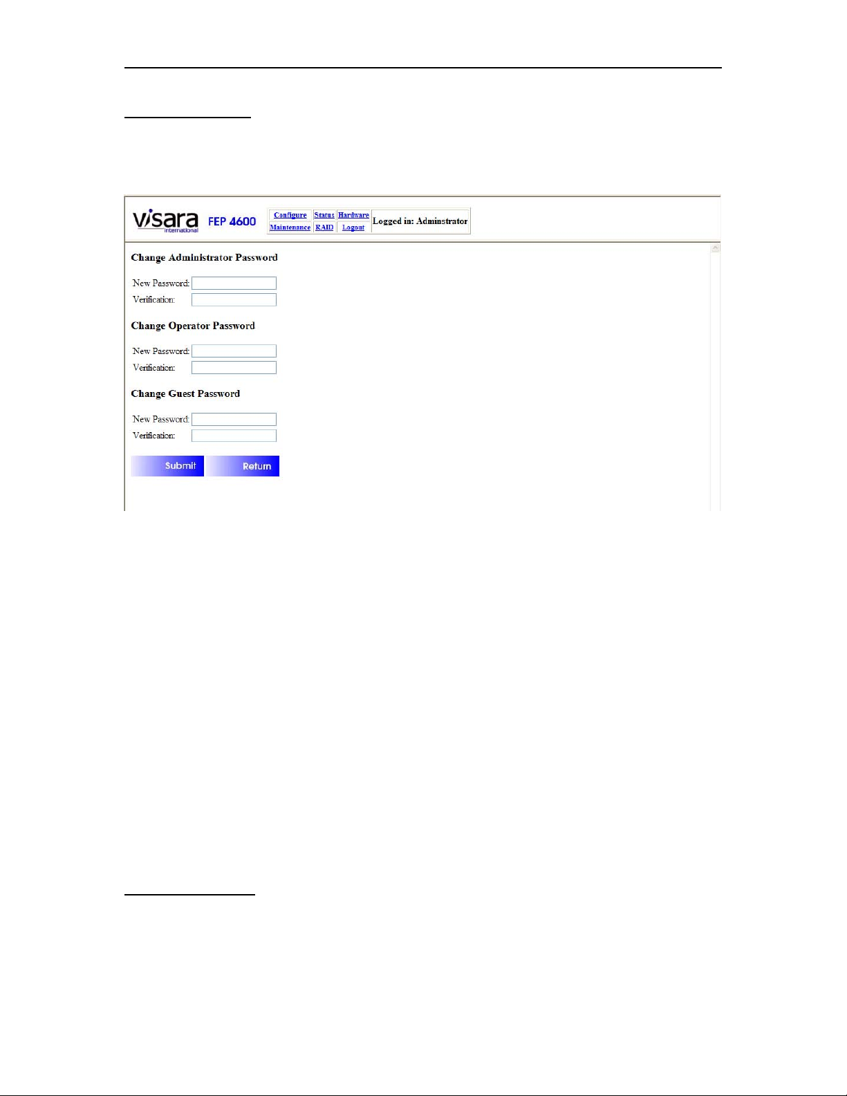
Change Password
If you are logged on as the administrator, selecting the Password button from the menu
will allow you to set the passwords.
There are three levels of users supported on the FEP-4600.
• Administrator
• Operator
• Guest
Each level of user can be protected with a different password.
For a description of the functions supported at each user level, refer to the FEP-4600
Users Guide and Maintenance Manual (P/N 707118-00x).
Type in the new password or passwords that you want, then type them again in the
Verification field. Press the Submit button when you are finished. If the New Password
and Verification fields have the identical information, then the passwords will be changed
immediately.
Note that if any of the passwords are not verified correctly, an error message will appear
and none of the passwords will be changed.
Button Definitions
Submit: The Submit button saves the changes. These changes should take affect
immediately (for the next login attempt).
Return: The Return button takes you back to the previous panel.
707119-001 3-7
Page 32
Chapter 3. Management Interface
Connectivity Options
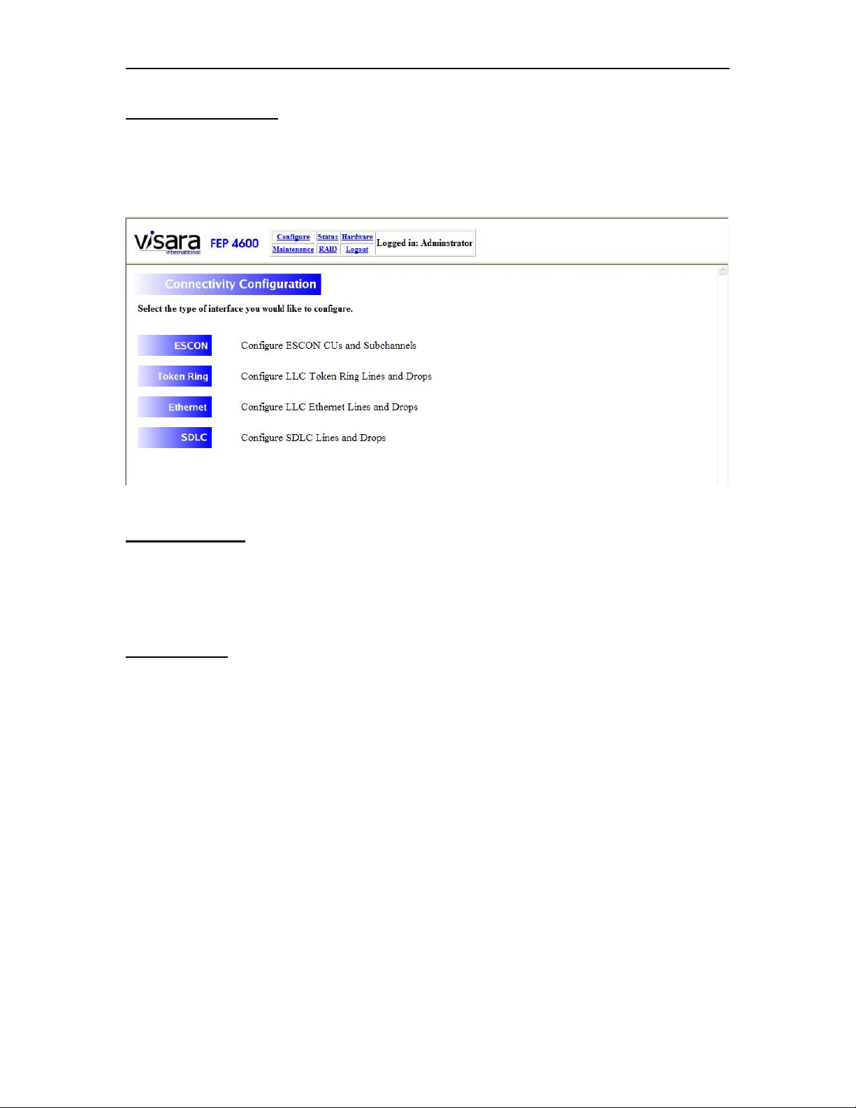
Selecting the ‘Connectivity’ option from the Configuration menu will result in the display
of the Connectivity menu. The menu items on this panel will vary according to the
hardware that is installed on your platform. This will be covered in later chapters.
Clustering Panel
Selecting the Clustering option from the Configuration panel will display the Clustering
panel. This will be covered later.
Circuits Panel
Selecting the Circuits option from the Configuration panel will display the Connectivity
Circuits panel. This too will be covered later.
3-8 707119-001
Page 33
FEP-4600 Installation and Configuration
Save/Restore Configuration Panel
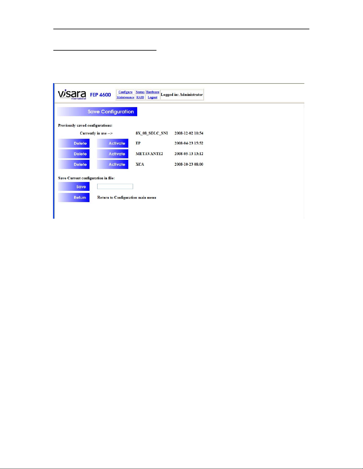
Selecting the Save/Restore option from the Configuration panel will display the
following panel.
From this panel you can save, delete, and restore configurations. Up to 4 configurations
for the FEP-4600 can be kept at one time; one active configuration and three previously
saved configurations. If you need to manage more than 4 configurations you may want to
employ the eManager product. With eManager you can push and pull configuration files
as needed.
When saving a configuration, a name is assigned and the date and time are recorded. This
information is displayed on this panel along with buttons that can be used to activate
inactive configurations, or delete them. The configuration that is currently active is
identified on this panel also. Changes made to the current configuration are saved as part
of the current configuration automatically. You do not need to save the current
configuration with this utility unless you desire to save a snapshot of what the current
configuration is (for possible use later).
A newly reactivated configuration will not take affect until the FEP-4600 is either
restarted or rebooted, depending on the option changes.
Among the options that would require a reboot are:
• ESCON Options have changed
• Ethernet MAC address has changed
• Token Ring MAC address has changed
707119-001 3-9
Page 34
Chapter 3. Management Interface
Saving the Current Configuration Changes:
Enter a file name into the field next to the [Save] button and press the [Save] button. If
you do not already have 4 configurations saved, the current configuration will be saved
and will appear in the list of configurations. If you do have 4 configurations saved
already, you will need to delete one of them to allow you to save the current
configuration.
Deleting a Configuration:
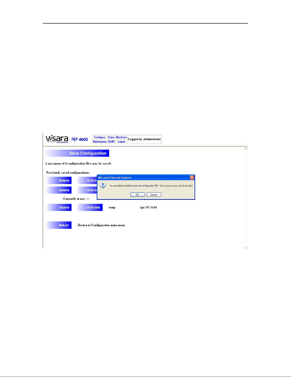
Press the [Delete] button next to the name of the configuration that you want to delete.
You will be given a chance to complete the deletion or to cancel the deletion request
through a prompt.
You are not allowed to delete the currently active configuration.
3-10 707119-001
Page 35
FEP-4600 Installation and Configuration
Activating a Stored Configuration:
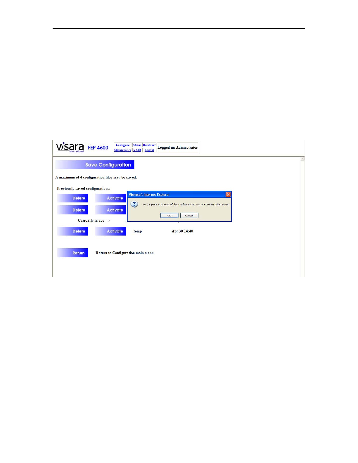
Press the [Activate] button next to the name of the configuration that you need to
activate. A message will display to advise you that you must restart the server after
completing the activation. You may press [OK] to proceed with the activation process or
press [Cancel] to abort the process.
Pressing the [OK] button copies the stored configuration file to be the current
configuration file, but does not operationally change how the server is functioning (it is
still running on the previously current configuration). You must manually restart or
reboot the server to make the activated configuration operational.
If you have not saved the current configuration prior to activating a previously saved
configuration, your current configuration will be lost.
707119-001 3-11
Page 36

Chapter 3. Management Interface
3-12 707119-001
Page 37
FEP-4600 Installation and Configuration
Chapter 4. ESCON Interface
The ESCON interface should be configured prior to configuration of the remote
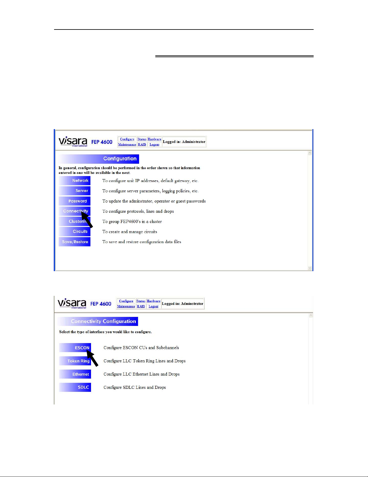
interfaces.
To configure the ESCON interface, select ‘Configure’ from the menu at the top of most
panels, to display the Configuration menu as shown below.
Select ‘Connectivity’ to display the Connectivity Configuration menu as shown below.
From this menu, you will need to select the ESCON option.
707119-001 4-1
Page 38
Chapter 4. ESCON Interface
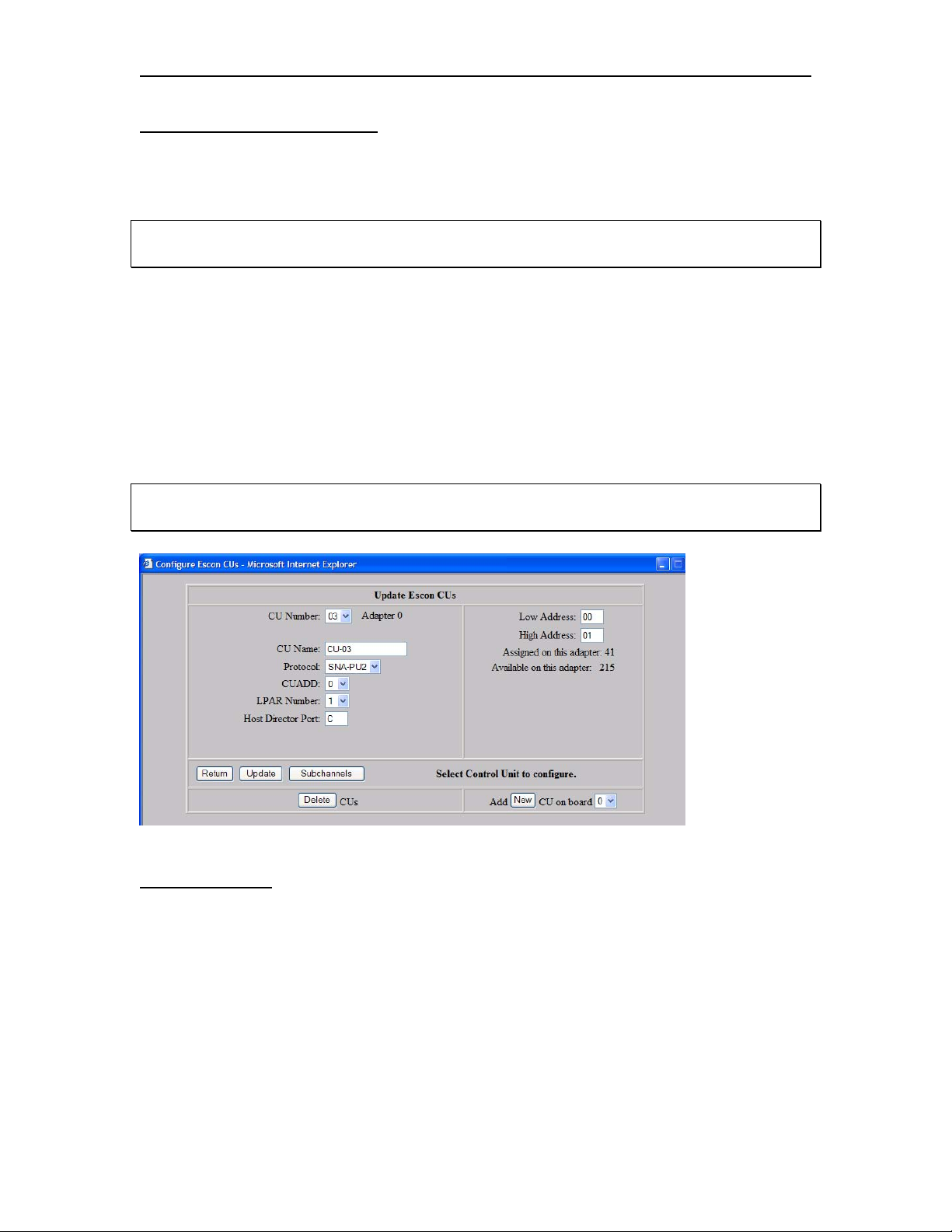
Configure ESCON CUs Panel
The following panel allows you to add or edit an ESCON CU definition. The definition
that you selected is the one that is displayed.
Note: If you are configuring the FEP-4600 for the first time, you will need to press the
‘New’ button to proceed.
You can select another definition once you are on this panel, by selecting a different CU
Number from the dropdown. If you have more than one ESCON Interface Board
installed, you can specify a different board by selecting the board at the bottom of the
panel.
Each CU definition for the FEP-4600 corresponds to a CNTLUNIT definition in the host
gen. Many of the options on this panel correspond to options of the CNTLUNIT macro,
so you will need to work closely with the person that creates the IO gen.
Note: If a single CNTLUNIT definition is used to define CUs for multiple LPARs, you
will need to create a separate CU definition for each LPAR that is to be supported.
Field Definitions
Field definitions for the Update ESCON CUs panel are as follows:
CU Number: This is a unique index field assigned to each CU (Control Unit) definition.
This field has no correspondence to anything in the host gen.
CU Name: The CU Name is a text field that you can enter a descriptive label for the CU
definition. It is wise to select a meaningful name that will correspond to what the CU
definition represents. Characters that may be used include alphanumeric characters as
well as the dash, underscore and period characters.
4-2 707119-001
Page 39

FEP-4600 Installation and Configuration
Protocol: The protocol field determines which channel protocol will be used for this CU
definition. Each CU definition is dedicated to a single protocol. Dependent upon the
selection of this option, other options may be revealed on this panel in the ‘Protocol
Options’ area. Values for this field are:
• SNA-PU 2 (3174) – This option is used for both PU 2.0 and PU 2.1. This
corresponds to a ‘UNIT=3174’ definition in the CNTLUNIT and IODEVICE
macros
• SNA-PU 4 (SCTC) – This option is used for supporting remote FEP, and
Channel-to-Channel connections and corresponds to a ‘UNIT = SCTC’ definition
in the CNTLUNIT and IODEVICE macros
• SNA-PU4 (3745) – This option is still in development but is intended to
correspond to a 3745 definition.
• NSNA (3174, 2701) – This option is used for supporting BSC lines. For 3270
operations, this may correspond to a ‘UNIT=3174’ in the CNTLUNIT macro, and
a ‘UNIT=3277’ or ‘UNIT=3286’ in the corresponding IODEVICE macros.
• EP-Bisync - For EP applications, ‘UNIT=NOCHECK’ in the CNTLUNIT macro
and ‘UNIT=2701’ in the IODEVICE macro may be required.
• XCA – For Supporting both PU 2.0 and 2.1 nodes. This allows use VTAM
Switched Major Node definitions.
CUADD: This value is defined by the CUADD option in the CNTLUNIT macro
corresponding to this definition. Valid values are represented by 0-F hex.
LPAR Number: This field defines which LPAR the CU definition will communicate
with on the host. Each CU definition on the FEP-4600 is dedicated to a single LPAR.
Valid LPAR numbers are represented by the hex numbers 1-F. For Shared subchannels,
where a single CNTLUNIT definition may be used to define a CU for more than one
LPAR, you will need to make multiple CU definitions on the FEP-4600 to support each
of these LPARs. The value of this field identifies which LPAR this CU corresponds to.
Host Director Port: The Host Director Port field refers to the port on an ESCON
director (switch) that is connected back to the Host CPU. When an ESCON director is not
being used, leave this value defined to be ‘FF’ (determine the port upon connection) or
you can set it to ‘01’ (directly attached to the CPU). This parameter is NOT the CHPID,
NOT the ESCON Director port that the FEP-4600 is connected to, and it is NOT the
LINK parameter in the CNTLUNIT macro.
Low Address: The Low Address field represents the low end of the UNITADD range as
defined in the CNTLUNIT definition.
High Address: The High Address field represents the high end of the UNITADD range
as defined in the CNTLUNIT definition.
CU on Board: Defines which ESCON board the CU definition is for.
707119-001 4-3
Page 40

Chapter 4. ESCON Interface
Button Definitions
Return: This button will return you to the previous panel. Changes that have not been
saved by pressing the ‘Update’ button will be lost.
Update: Pressing the Update button saves the changes made on this panel for use the
next time the ESCON interface is loaded. If there are any detected error conditions, an
error message will be displayed to the right of the buttons and the changes are not saved.
Subchannels: Pressing this button allows you to configure the subchannels for the
selected CU
Delete (CU): Pressing this button will cause a panel to be displayed showing the
currently defined CUs. See ‘Deleting CUs’ below.
New: Will cause several of the fields to revert to their defaults and causes the CU
Number field to indicate the next CU definition available to allow you to define a new
CU definition. When the CU definition is complete, press the ‘Update’ button to
complete the CU addition function.
Other Panel Information
Assigned Addresses: Provides an indication of how many of the 256 subchannel
addresses supported by the selected ESCON interface have been assigned already.
Available Addresses: Provides an indication of how many of the 256 subchannel
addresses supported by the selected ESCON interface are still available for assignment.
4-4 707119-001
Page 41
FEP-4600 Installation and Configuration
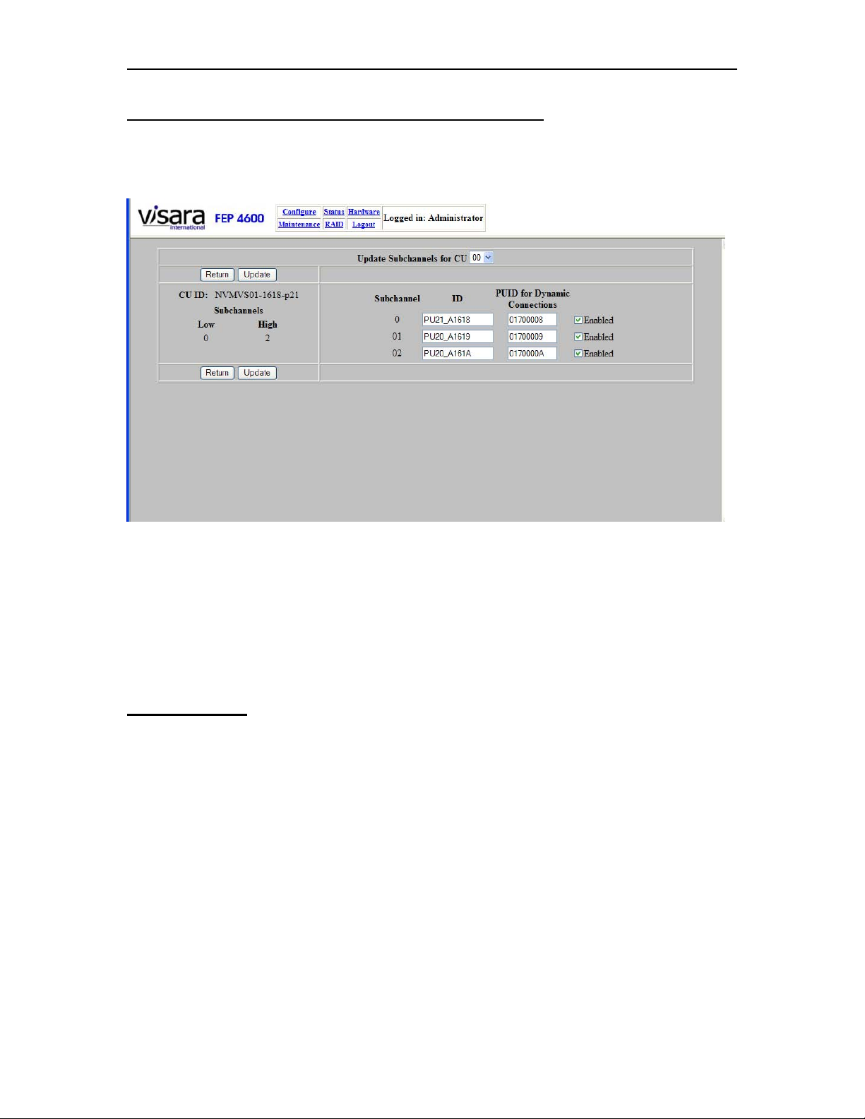
Configuring Subchannels for Protocol ‘SNA-PU2 (3174)’)
Pressing the ‘Subchannel’ button causes the following panel to display when the selected
CU is for a PU type 2.
This panel displays each of the subchannel addresses that are included in the address
range that was configured on the previous panel. You may modify the fields on this panel
and save the changes as needed.
The dropdown control located in the upper center portion of the panel allows you to
select and display other CUs defined for this ESCON interface.
Field Definitions
ID: This column displays the name assigned to each of the subchannels by the
administrator. These names can be most any text character string that you choose to use
(use alphanumeric characters as well as dash, underscore, and period), and should be
selected to describe the interface uniquely.
PUID for Dynamic Connections: This is an 8 character (hex) field for use with
switched connections only. (Static connections will be defined on the Circuits panel.) For
this protocol type, the FEP-4600 uses Local SNA Major Node definitions in place of the
Switched Major Node definitions used with traditional 37x5 Front End Processors, to
define the interface to remote switched SNA nodes. Switched Major Node PU definitions
typically contained the IDBLK and IDNUM parameters. Together the IDBLK + IDNUM
parameters specified eight hex characters used to match and qualify connecting SNA
nodes with the correct VTAM PU definition. This responsibility is handled in the FEP4600 by defining the same 8-character string to the PUID field. When the connecting
707119-001 4-5
Page 42

Chapter 4. ESCON Interface
SNA node is challenged for an XID, the 8 character XID sequence will be matched to the
PUID definition, and the appropriate upstream host connection will be made. Each PUID
defined must be unique. Note that most 3270 controllers use ‘017’ for the first 3
characters, and can not be changed to use something else.
If there is no match for the XID sequence to a configured subchannel (and there was no
match of the downstream IP Address to a configured circuit), then the connection will be
disallowed.
Hint: If you wish to track dynamic connections by their PUID, you can make the PUID
part of the ID that you assign. For example you can use a name such as ‘Acct_01702951’.
Enable Checkbox: This checkbox indicates whether this definition is to be considered
an active connection or not. If the checkbox is not checked, the definition will be ignored,
and the status panels will not reflect that the definition exists. (Green status will reflect
that all of the “enabled” interfaces are up as they should be.)
Button Definitions
Return: Selecting this button will return you to the ‘Update ESCON CU’ panel.
Update: Selecting the ‘Update’ button will save any changes that you have made on this
panel. A message indicating ‘Subchannel update complete!’ should display.
4-6 707119-001
Page 43
FEP-4600 Installation and Configuration
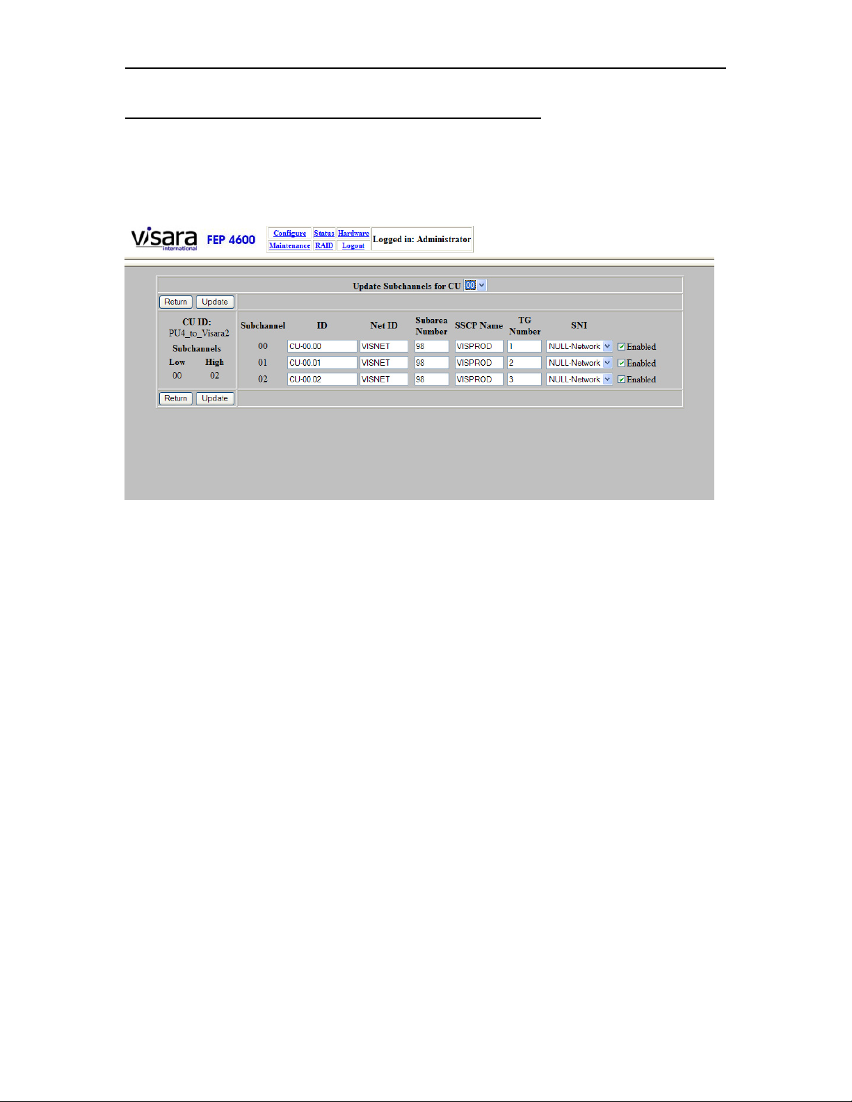
Configuring Subchannels for Protocol ‘SNA-PU4 (SCTC)’
Pressing the ‘Subchannel’ button causes the following panel to display when the selected
CU is for a PU type 4.
This panel displays each of the subchannel addresses that are included in the address
range that was configured on the previous panel. You may modify the fields on this panel
and save the changes as needed.
The dropdown control located in the upper center portion of the panel allows you to
select and display other CUs defined for this ESCON interface.
707119-001 4-7
Page 44
Chapter 4. ESCON Interface
Field Definitions
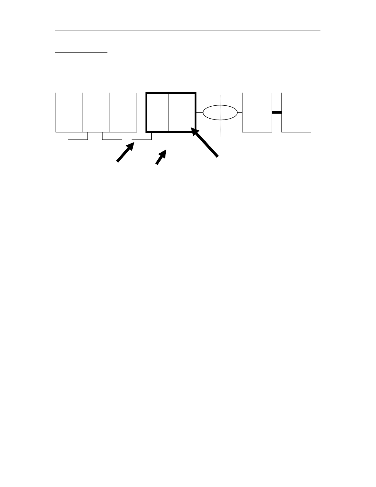
Refer to the diagrams below to better understand what the Field Definitions represent.
CPU FEP-4600
Null Network
3745 CPU
VTAM
1
SA01
VTAM
SA02
2
Gateway
VTAM
3
SA03
CTC CTC
TG Number
VTAM
CTC
NETID=NET1
Net ID Option
Gateway
NCP
4
SA04
SA99SA98
NETID=NULL
Subarea
Number
Option
NCP
14
SA14
NETID=NET2
VTAM
10
SA10
ID: This column displays the name assigned to each of the subchannels by the
administrator. These names can be most any text character string that you choose to use
(use alphanumeric characters as well as dash, underscore, and period), and should be
selected to describe the interface uniquely. A default ID will be assigned, but you can
modify the ID to whatever you want.
Net ID: This option corresponds to the NETID used by the Adjacent VTAM that the
FEP-4600 is connected to through the ESCON interface. (Local NETID)
Subarea Number: This represents the subarea number used by the FEP-4600 as it
would appear from the ESCON channel side. Note that when this circuit is providing a
connection to another VTAM through an ESCON interface (Channel-to-Channel), the
subarea number should be that of the destination VTAM.
SSCP Name: This is the name that the FEP-4600 will identify itself to the ESCON
attached VTAM when establishing a connection.
4-8 707119-001
Page 45
FEP-4600 Installation and Configuration
TG
VTAM
1
SA01
FEP-4600
VTAM
10
SA10
Subarea Number
Configured
Interface
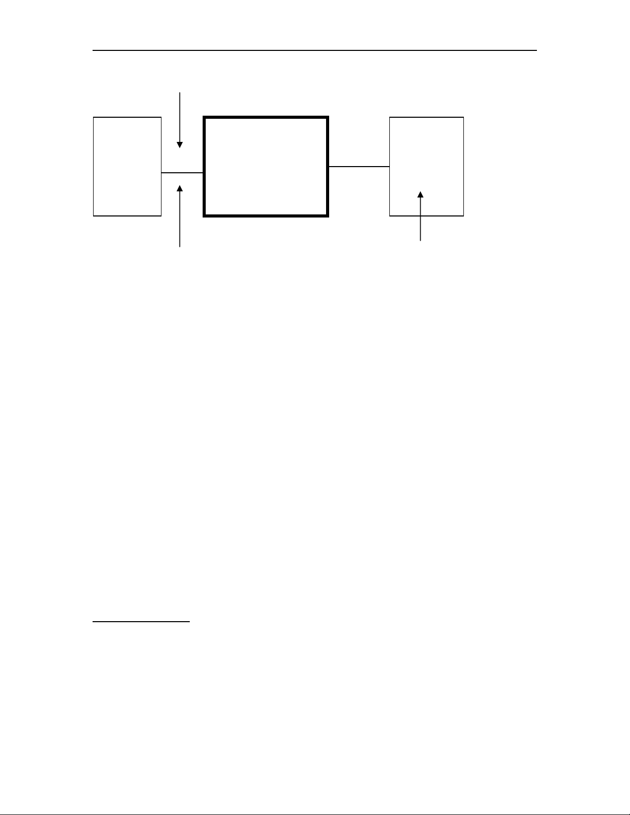
TG Number: This number represents the TG number that has been genned in the
Adjacent VTAM for the ESCON interface between the FEP-4600 and VTAM.
SNI: This option describes the SNI function that this connection is to perform. Options
are:
None: No SNI is being performed or the SNI is being handled entirely by a
remote NCP. This option is also typically selected for channel-to-channel
connections.
Single Sided: The FEP-4600 is replacing a Gateway NCP in a single sided SNI
network connection (the remote NCP does not perform a Gateway NCP function).
Null SNI: The FEP-4600 is to participate in a Null SNI network connection. This
option would also be used if a channel-to-channel connection between VTAM
and TPF is being configured.
Enable Checkbox: This checkbox indicates whether this definition is to be considered
an active connection or not. If the checkbox is not checked, the definition will be ignored,
and the status panels will not reflect that the definition exists. (Green status will reflect
that all of the “enabled” interfaces are up as they should be.)
Button Definitions
Return: Selecting this button will return you to the ‘Update ESCON CU’ panel.
Update: Selecting the ‘Update’ button will save any changes that you have made on this
panel. A message indicating ‘Subchannel update complete!’ should display.
707119-001 4-9
Page 46
Chapter 4. ESCON Interface
Configuring Subchannels for Protocol ‘XCA’
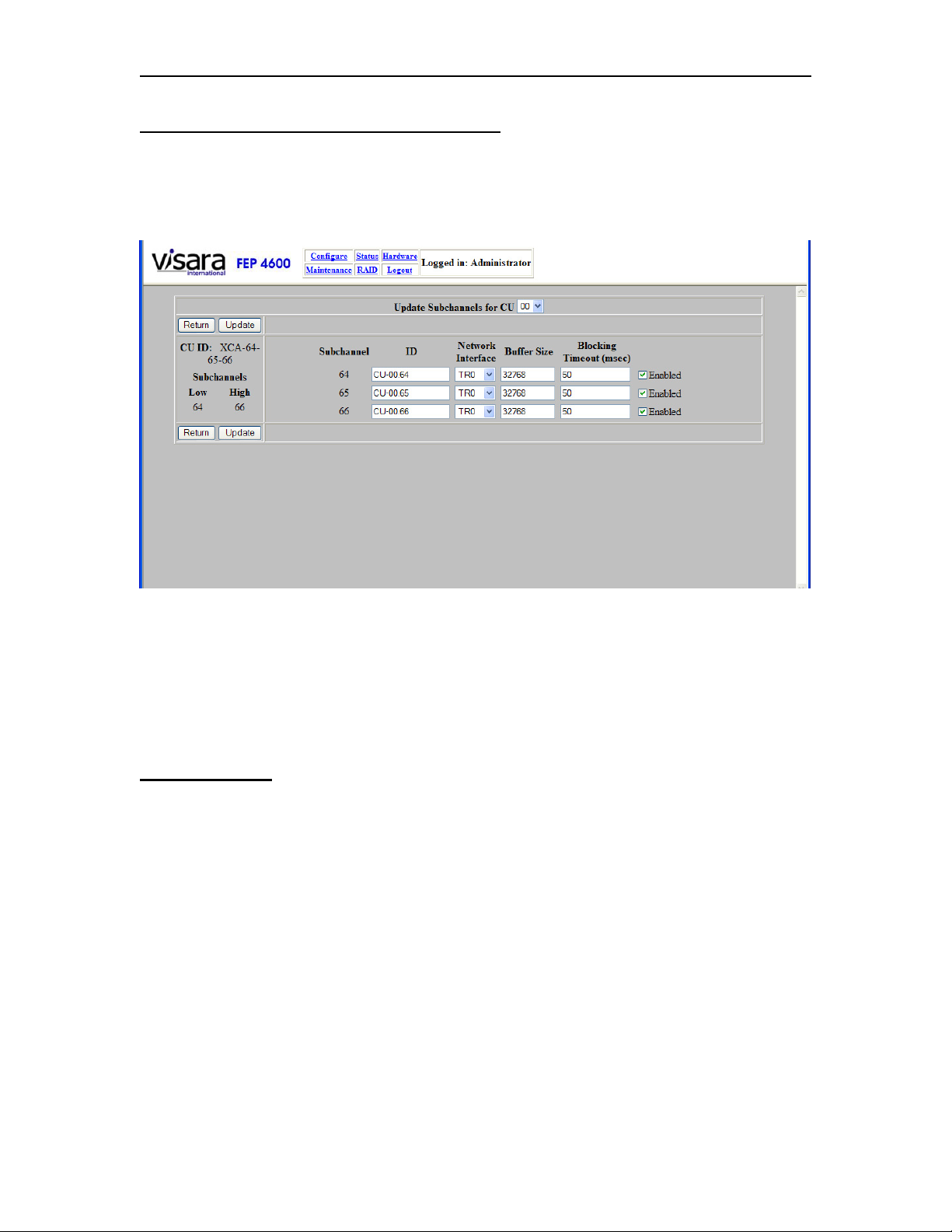
Pressing the ‘Subchannel’ button causes the following panel to display when the selected
protocol is XCA.
This panel displays each of the subchannel addresses that are included in the address
range that was configured on the previous panel. You may modify the fields on this panel
and save the changes as needed.
The dropdown control located in the upper center portion of the panel allows you to
select and display other CUs defined for this ESCON interface.
Field Definitions
ID: This column displays the name assigned to each of the subchannels by the
administrator. These names can be most any text character string that you choose to use
(use alphanumeric characters as well as dash, underscore, and period), and should be
selected to describe the interface uniquely.
Network Interface: This identifies the adapter number associated with this XCA
definition. Each XCA definition is limited to 255 downstream PUs. Multiple XCA
definitions may be assigned to the same adapter however. Eligible adapters (Token Ring
and Ethernet) are listed in the dropdown control.
Buffer Size: This is the maximum amount of inbound data that is to be supported
through this XCA interface for an inbound transfer. If this amount of inbound data is
queued an inbound frame will be generated.
4-10 707119-001
Page 47

FEP-4600 Installation and Configuration
Blocking Timeout (msec): Once inbound data begins to queue, this is the maximum
amount of time that the FEP-4600 is to wait, before an inbound block is generated and
sent.
Enable Checkbox: This checkbox indicates whether this definition is to be considered
an active connection or not. If the checkbox is not checked, the definition will be ignored,
and the status panels will not reflect that the definition exists. (Green status will reflect
that all of the “enabled” interfaces are up as they should be.)
Button Definitions
Return: Selecting this button will return you to the ‘Update ESCON CU’ panel.
Update: Selecting the ‘Update’ button will save any changes that you have made on this
panel. A message indicating ‘Subchannel update complete!’ should display.
707119-001 4-11
Page 48
Chapter 4. ESCON Interface
Configuring Subchannels for Protocol ‘NSNA (3174, 2701)’
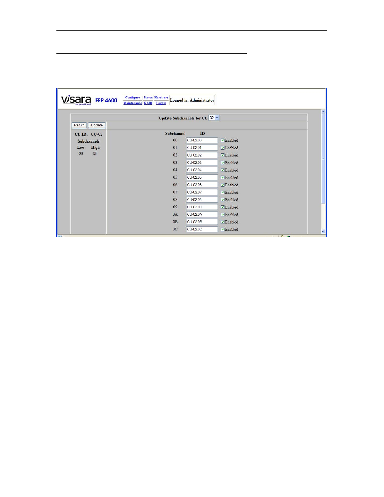
Pressing the ‘Subchannel’ button causes the following panel to display when the selected
protocol is NSNA.
This panel displays each of the subchannel addresses that are included in the address
range that was configured on the previous panel. You may modify the fields on this panel
and save the changes as needed.
The dropdown control located in the upper center portion of the panel allows you to
select and display other CUs defined for this ESCON interface.
Field Definitions
ID: This column displays the name assigned to each of the subchannels by the
administrator. These names can be most any text character string that you choose to use
(use alphanumeric characters as well as dash, underscore, and period), and should be
selected to describe the interface uniquely.
Enable Checkbox: This checkbox indicates whether this definition is to be considered
an active connection or not. If the checkbox is not checked, the definition will be ignored,
and the status panels will not reflect that the definition exists. (Green status will reflect
that all of the “enabled” interfaces are up as they should be.)
4-12 707119-001
Page 49

FEP-4600 Installation and Configuration
Button Definitions
Return: Selecting this button will return you to the ‘Update ESCON CU’ panel.
Update: Selecting the ‘Update’ button will save any changes that you have made on this
panel. A message indicating ‘Subchannel update complete!’ should display.
707119-001 4-13
Page 50
Chapter 4. ESCON Interface
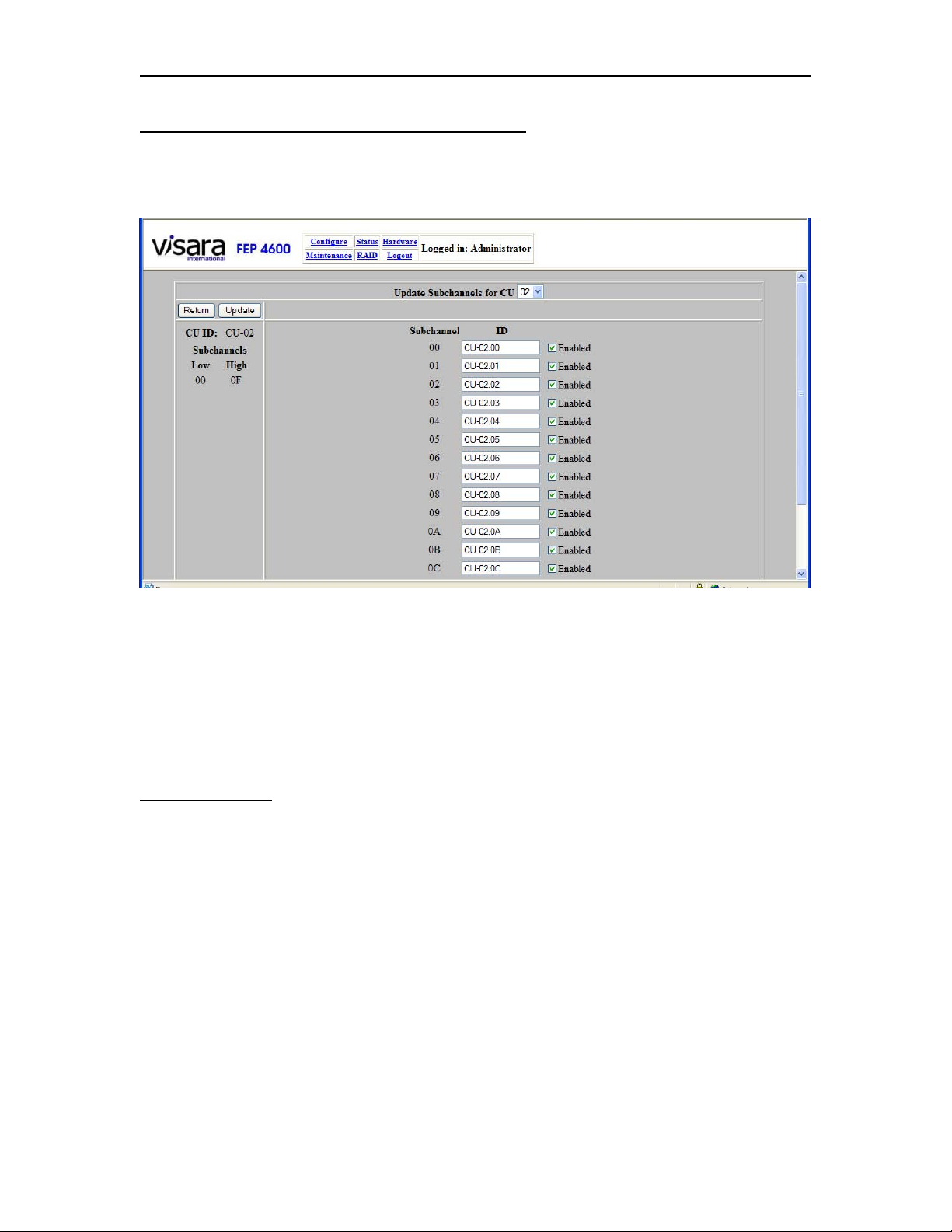
Configuring Subchannels for Protocol ‘EP-BSC’
Pressing the ‘Subchannel’ button causes the following panel to display when the selected
protocol is EP-BSC.
This panel displays each of the subchannel addresses that are included in the address
range that was configured on the previous panel. You may modify the fields on this panel
and save the changes as needed.
The dropdown control located in the upper center portion of the panel allows you to
select and display other CUs defined for this ESCON interface.
Field Definitions
ID: This column displays the name assigned to each of the subchannels by the
administrator. These names can be most any text character string that you choose to use
(use alphanumeric characters as well as dash, underscore, and period), and should be
selected to describe the interface uniquely.
Enable Checkbox: This checkbox indicates whether this definition is to be considered
an active connection or not. If the checkbox is not checked, the definition will be ignored,
and the status panels will not reflect that the definition exists. (Green status will reflect
that all of the “enabled” interfaces are up as they should be.)
4-14 707119-001
Page 51

FEP-4600 Installation and Configuration
Button Definitions
Return: Selecting this button will return you to the ‘Update ESCON CU’ panel.
Update: Selecting the ‘Update’ button will save any changes that you have made on this
panel. A message indicating ‘Subchannel update complete!’ should display.
707119-001 4-15
Page 52
Chapter 4. ESCON Interface
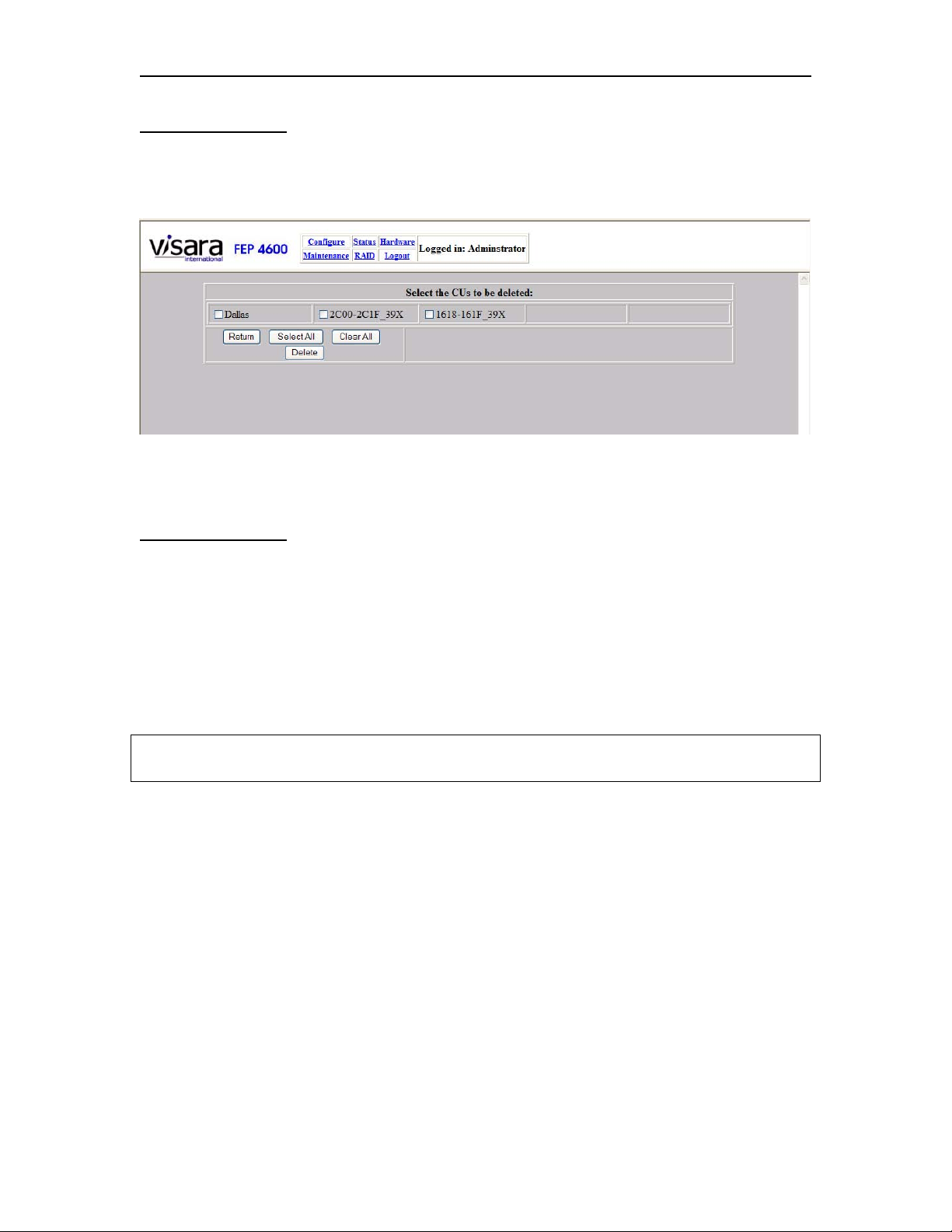
Deleting CU Panel
When pressing the ‘Delete’ button on the ‘Update ESCON CUs’ panel, the following
panel will be displayed showing all currently configured CUs.
Make a selection of one or more CU definitions that you wish to delete; then press the
‘Delete’ button. The panel will be updated to show just the remaining CU definitions.
Button Definitions
Return: Pressing this button returns you to the ‘Update ESCON CUs’ panel.
Select All: Pressing this button will select all currently displayed CUs.
Clear All: Pressing this button will clear the selection of all displayed CUs.
Delete: Pressing this button will result in the warning message:
‘You are about to delete the selected CUs and all of their defined subchannels! Are you
sure you want to do this?’
You can press ‘OK’ to finish processing the deletion process or press ‘Cancel’ to abort
the deletion process.
4-16 707119-001
Page 53
FEP-4600 Installation and Configuration
Chapter 5. Token Ring Interface
The Token Ring interface should be configured after the ESCON interfaces are
configured and prior to configuration of the circuits.
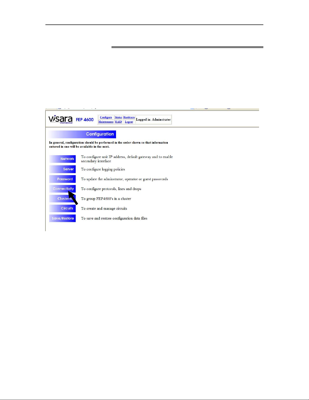
To configure the Token Ring interface, select ‘Configure’ from the menu at the top of
most panels, to display the Configuration menu as shown below.
Select ‘Connectivity’ to display the Connectivity Configuration menu as shown below.
707119-001 5-1
Page 54
Chapter 5. Token Ring Interface
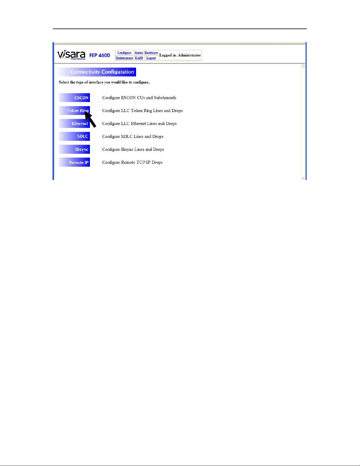
From this menu, you will need to select the Token Ring option.
5-2 707119-001
Page 55
FEP-4600 Installation and Configuration
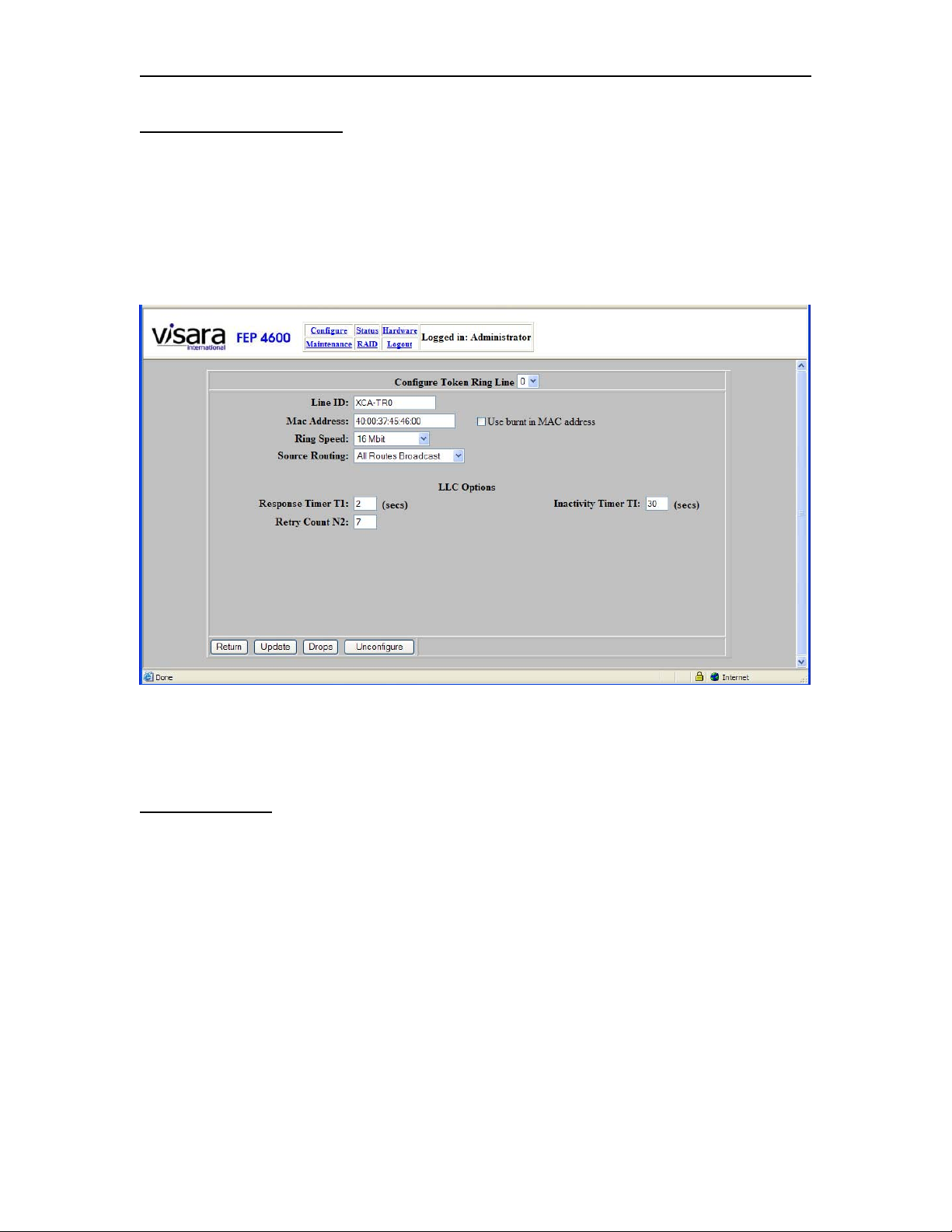
Token Ring Line Options
The Token Ring configuration for the FEP-4600 is performed in two steps. The first step
is to configure the Token Ring Line Options, which define the way the Token Ring
interface will interact with the network to which it will be attached. The second step is to
configure the interface to each drop on the Token Ring that the FEP-4600 is to
communicate with.
Changes can be made to the options found on this panel, then press the Update button to
save the changes. Descriptions of the options found on the ‘Configure Token Ring Line’
panel are discussed below:
Field Definitions
Configure Token Ring Line - This option identifies which line you are about to
configure. If you find that you have selected the wrong line, you can select the correct
Token Ring line from the drop down control.
Line ID - This option allows you to apply a name to the Token Ring interface (valid
characters are alphanumeric characters plus the underscore, dash, and period characters).
MAC Address: You will need to define which LAN address the FEP-4600 will use for
this Token Ring interface. The selection of this address is important. If the FEP-4600 is
replacing an existing 37x5 FEP or a Token Ring gateway product, the downstream
platforms that are communicating to that product, already include in their configurations
the Token Ring address of that gateway/FEP product. To avoid having to reconfigure all
707119-001 5-3
Page 56

Chapter 5. Token Ring Interface
of those platforms, you may want to set the Token Ring address of the FEP-4600 to that
same address.
Selecting a MAC Address of ‘00:00:00:00:00:00’ will cause the Token Ring interface to
use the burned in address associated with the board itself. This is not recommended.
Since downstream platforms are configured for the MAC address of this unit, replacing
the board in the FEP-4600 would require reconfiguration of all downstream units. Any
other address entered will be used to override the burned in address. Traditionally, locally
administered Token Ring addresses use the format 40:00:xx:xx:xx:xx, where ‘x’ can be
any valid hex digit.
Note that you can not attach the FEP-4600 to the same Token Ring as the platform you
are replacing and have them powered on at the same time if you have duplicate addresses.
(If you have a duplicate address situation, the FEP-4600 will not be allowed to insert into
the ring.) If you want to conduct tests where the FEP-4600 has the same address as the
platform it is replacing, you have two options.
1) Put the FEP-4600 on the same Token Ring as the FEP or Gateway that it is
replacing. You will need to have only one unit (FEP-4600 or FEP/Gateway)
physically inserted in the ring at any given instant.
2) Put the FEP-4600 on a different Token Ring segment, separated from the original
Token Ring by a Source Routing Bridge. With a Source Routing Bridge
separating the two rings, you may use the same Token Ring address on each of
the rings. Assuming that the downstream stations are configured to support
Source Routing, the downstream stations will connect to whichever upstream
responds first. If the upstream and downstream station are on the same ring, that
upstream will normally respond first.
Ring Speed: For the Ring Speed option, you can configure the Token Ring interface to
auto-negotiate (default) or you can preset it to one of the supported speeds. The full set of
options is:
• Auto Negotiate
• 4 Mbps
• 16 Mbps
• 100 Mbps (works same as Auto Negotiate)
Source Routing: There are three possible configurations for this option.
• All Routes Broadcast – Source Route Bridging is used. Broadcasts to establish a
session will attempt to get to the destination over all possible routes.
• Single Route Broadcast – Source Route Bridging is used. An administrator must
configure which bridges are to be used to pass broadcasts and which ones are not,
thus reducing the number of paths that a broadcast frame has to traverse. (This is
configured on the bridges themselves, not in the FEP-4600.)
• Disable – Source Route Bridging will not be used
Use Burnt in MAC Address: Checking this box will cause the MAC address burned in
by the manufacturer to be displayed and used.
5-4 707119-001
Page 57

FEP-4600 Installation and Configuration
Response Timer T1: The value for this timer is an indication of how long the FEP-4600
should wait for an LLC response to a frame before attempting a retry. Commonly used
values would be:
• 2 Seconds (Default) used for LAN connections
• 3 Seconds typically used for WAN connections over leased lines
• 10 Seconds suggested value for WAN connections over Frame Relay
Retry Count N2: The value for this option determines how many attempts will be made
to retry sending a frame at the LLC level, before declaring that an LLC timeout has
occurred. The default value for this option is 7.
Inactivity Timer TI: This option determines how long the FEP-4600 should wait to
attempt to test the interface when there is no activity. A typical value for this parameter is
30 seconds.
Button Definitions
Return: Pressing the Return button takes you back to the previous panel.
Update: Pressing the Update button will save the current values. If there is a value in
error, a message will display to the right of the buttons to alert you to the error situation,
and the values will not be saved.
Drops: Selecting the Drops button will display the Token Ring Drops panel to allow you
to edit the configurations of currently defined drops, and allow you to define new drops.
Unconfigure: Using this button allows you to delete the currently displayed
configuration.
707119-001 5-5
Page 58

Chapter 5. Token Ring Interface
Drop Panel Option Determination
Below you will find a discussion on how to determine values for some of the options
found on the Token Ring Drop Panels.
Static vs Dynamic Drops
Token Ring Drops on the FEP-4600 can be set up two different ways.
• Static
• Dynamic
Static Drops:
Static drops offer simplicity and security. Defining a static drop means that you will
configure the MAC address and SAP of the downstream platform. Only that platform can
connect to this circuit. The Token Ring end of the circuit must be configured to a specific
upstream (ESCON) subchannel address in the FEP-4600 configuration (see chapter on
Static Gateway Circuits).
Dynamic Drops:
Dynamic drops offer flexibility and may be used as part of a disaster recovery scenario.
Defining a dynamic drop means that any downstream platform configured to seek out the
MAC address of the FEP-4600 interface, and connecting to the Local SAP associated
with this drop definition, will be allowed to attempt to make a connection. The
downstream platform will be challenged by the FEP-4600 for an SNA XID. The XID
response from the downstream platform will be matched to a configured upstream
(ESCON) subchannel address that is configured for that specific XID (IDBLK + IDNUM
options). If a match is found, the upstream to downstream circuit will be generated
dynamically (for the length of the session). If no match is found, the downstream
platform will be disconnected. A maximum of 16 dynamic circuits per interface will be
permitted.
SAP Assignments
The same Local SAP number can be used for multiple drops and will automatically
default to a value of ‘04’ on the FEP-4600. SAPs used for SNA communication must be a
multiple of ‘04’ hex (04, 08, 0C, 10, 14, etc.), and must be between the values of 04-EC.
If more than one PU connection is to be made between the FEP-4600 and the same
platform (same LAN address), a unique combination of Remote SAP address and Local
SAP address must be used for each circuit (drop). For example a combination of RSAP =
04, LSAP=04 and RSAP=08, LSAP=04 would be a valid configuration for a downstream
platform that requires two PUs to be defined. SAP numbers are assigned on both
platforms conducting the PU session, and typically must be configured to communicate
with each other. On the FEP-4600, when defining Dynamic Connections or XCA drops,
use a different SAP for each of those that is not duplicated by the static PU2 connections
or PU4 connections.
5-6 707119-001
Page 59

FEP-4600 Installation and Configuration
Window Size Selection
The Transmit and Receive Windows Size parameters are part of a static sliding Window
algorithm used by LLC for controlling packet flow. There is a separate set of Transmit
and Receive Window settings for each end of an LLC circuit. Coordinating the values
used is recommended.
The Transmit Window represents the maximum number of outstanding packets (packets
without a response or acknowledgement) a platform can send before having to stop and
wait for a response to one of the packets. Setting the Transmit Window too small may
result in a platform having to stop and wait for a response often, causing poor response
times. Setting the value too high, may result in having to retransmit several packets,
whenever a packet gets clobbered or lost. (If a negative acknowledgement is received for
a packet, then that packet and subsequent packets that have already been sent must be
resent.)
The Receive Window represents how many packets in a single conversation can be
received before an acknowledgement must be queued to be sent. If a Receive Window
size is set too large, the receiver may be waiting to receive additional packets that are not
forthcoming, resulting in unnecessary delays in sending acknowledgements.
As a general rule, you want to keep the Transmit Window set to a higher value than the
Receive Window. This allows the transmitter to keep sending packets, and with the lower
Receive Window at the session partner, the partner will send acknowledgements back
sooner than required. As the transmitter receives acknowledgements, the number of
outstanding unacknowledged packets will decrement allowing for even more packets to
be sent. The longer the path from transmitter to receiver, the larger difference you may
want between Transmit and Receive Windows. (This is the sliding window.) This works
well for LAN environments, but may not for WAN environments.
In WAN environments packets can be distorted or lost or delayed to the point where an
earlier packet arrives after a later packet. In cases where there is an apparent sequence
number error, the normal recovery is for the LLC circuit to be taken down and brought
back up. This can result in abnormal termination of a session. Keeping the Transmit and
Receive Windows set to 1 ensures that there are no sequence number errors.
The rules of thumb for setting the Window sizes are as follows:
1) For a LAN environment use a Transmit Window size of 2 + an additional
value of 1 for each hop (bridge or router that is crossed) between the
transmitter and receiver, up to the maximum value.
2) Keep the Receive Window set to the common default of 1.
3) For a WAN environment with frequent congestion or unreliable delivery, use
a Transmit Window of 1 and a Receive Window of 1.
707119-001 5-7
Page 60
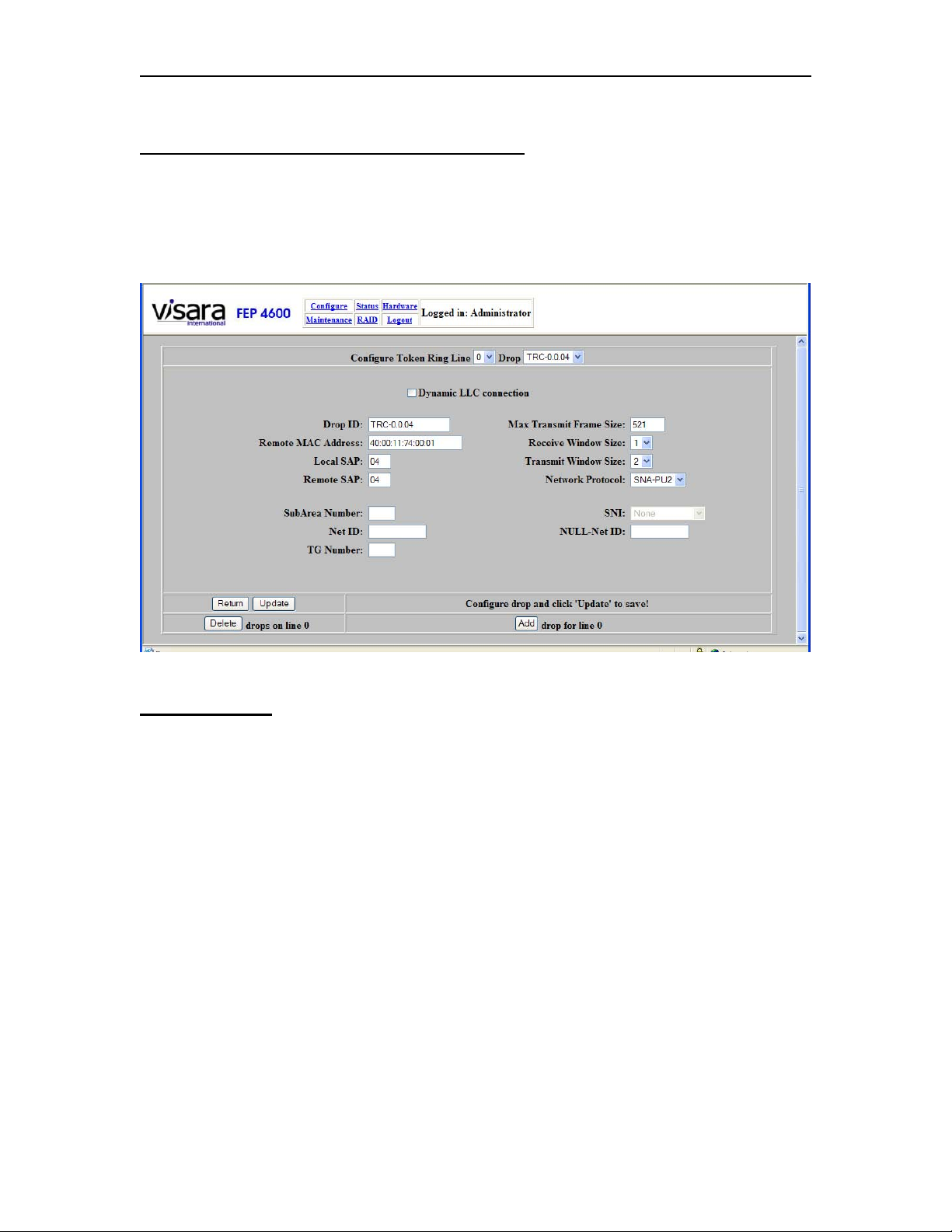
Chapter 5. Token Ring Interface
Token Ring Drop Panel for Protocol ‘SNA-PU2’
Pressing the [Drops] button on the Token Ring Line panel causes the Token Ring Drop
panel to display. This panel allows you to define a Token Ring drop that will be
associated with an upstream ESCON Local Major Node definition on the host. An
example of this panel (PU2 Drop) appears below.
Field Definitions
An explanation of the options found on the Drop panel can be found below:
Configure Token Ring Line: This option allows you to specify a different Token Ring
line, if the one that is currently selected is not the one that you wish to make changes to.
Drop: This field displays a list of names given to drops that have been defined thus far
by the administrator. As each new drop is defined, it will be added to the list.
Dynamic LLC Connection: When this box is checked, this definition will be used for
dynamic connections. When a remote station connects, it will be challenged for its SNA
XID (PUID). This XID will be used to dynamically connect the station to an upstream
ESCON subchannel that is configured to match the XID (PUID). Selecting Dynamic
LLC will force the remote MAC address in the configuration to ’00:00:00:00:00:00’ and
gray out the ‘Remote MAC Address’ and ‘Remote SAP’.
5-8 707119-001
Page 61

FEP-4600 Installation and Configuration
Drop ID: The ‘Drop ID’ is the name that is being given to this drop, and is the same
name that will be added to the list of drops when this definition is saved. The name can
be most any text string (alphanumeric characters plus dash, underscore, and period
characters), and should be created by the administrator to provide a name for the drop
that is most useful to describe what or where it is.
Remote MAC Address: This is the LAN address of the platform that the FEP-4600 is
talking to on this drop. This address might also be referred to as the remote platform’s
hardware address or LLC address. Note that an address of ‘00:00:00:00:00:00’ will
indicate that this drop has been configured to be dynamic (’00:00:00:00:00:00’ is not
accepted for a static definition). Any other address makes this definition static. See the
discussion below about dynamic versus static drops.
Local SAP: This option defines the local Service Access Point address that is assigned
by the FEP-4600 for use for communications with the remote platform. Refer to the ‘SAP
Assignments’ section above for selecting a valid SAP value. Note that if you have the
Dynamic Connections option selected, the SAP used for the dynamic connections should
be different than the one used for static connections.
Remote SAP: This option defines the remote Service Access Point address that is
configured on the remote platform that the FEP-4600 is communicating with. Refer to the
‘SAP Assignments’ section below for a discussion on selecting valid SAP values.
Max Transmit Frame Size: This value represents the maximum size frame (including
TH, RH, and RU) that may be sent in a single packet over the LLC link. Most Token
Ring LLC circuits are limited to a maximum frame size of 4105, but some (usually older)
platforms may be limited to a smaller maximum frame size. Using a smaller value than
what is supported by the session partner will work, but will result in the transmission of
more packets than if a larger value is set. The minimum size for a PU type 2 is 265. The
default value for this option is 521. Note that if the traffic is to cross an Ethernet LAN
segment to get to the session partner, then the maximum value must be restricted to that
handled by Ethernet (a value of 1490).
Receive Window Size: This is the maximum number of packets in an LLC conversation
with a session partner that can be received, before an LLC acknowledgement must be
sent. The default value for this option is 1. Refer to the ‘Window Size Selection’ section
below.
Transmit Window Size: This is the maximum number of packets that will be sent
before requiring an LLC acknowledgement. The default value for this option is 2. Refer
to the ‘Window Size Selection’ section below.
707119-001 5-9
Page 62

Chapter 5. Token Ring Interface
Network Protocol: You must select which protocol the FEP-4600 is to use when
communicating with the remote station over this circuit. The options are:
• SNA-PU2 – Use this when the remote platform is a PU 2 control unit or PC
emulating a PU type 2.
• SNA-PU4 – Use this selection when the remote platform is a 37x5 Front End or
another FEP-4600.
• XCA – Use this value when the remote platform is a PU 2 platform and the host
definition is part of a Switched Major Node definition.
Button Definitions
Return: Selecting this button will return you to the ‘Update ESCON CU’ panel.
Update: Selecting the ‘Update’ button will save any changes that you have made on this
panel. A message indicating ‘Subchannel update complete!’ should display.
Delete: Pressing this button will bring up the Delete Drops panel.
Add: Pressing this button will add a new Drop definition and set several of the options
to default values. You must remember to press the [Update] button when you are finished
modifying the values to save the new drop information.
5-10 707119-001
Page 63
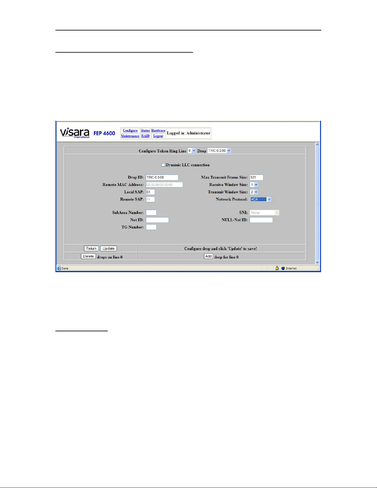
FEP-4600 Installation and Configuration
Token Ring Drop Panel for Protocol ‘XCA’
Pressing the [Drops] button on the Token Ring Line panel causes the Token Ring Drop
panel to display. By default the Network Protocol is set to ‘SNA-PU2’. To change this to
an XCA definition, select ‘XCA’ from the Network Protocol dropdown control. An XCA
definition is matched in the FEP-4600 configuration to an ESCON XCA definition. This
allows network attached PU2 devices to communicate to Switched Major Node PU2
definitions on the host. An example of this panel (XCA Drop) appears below.
Although many parameters are displayed, most are not used by XCA and cannot be
defined or changed. An explanation of the valid options for XCA found on the Drop
panel can be found below:
Field Definitions
Configure Token Ring Line: This option allows you to specify a different Token Ring
line, if the one that is currently selected is not the one that you wish to make changes to.
Drop: This field displays a list of names given to drops that have been defined thus far
by the administrator. As each new drop is defined, it will be added to the list.
Drop ID: The ‘Drop ID’ is the name that is being given to this drop, and is the same
name that will be added to the list of drops when this definition is saved. The name can
be most any text string (alphanumeric characters plus dash, underscore, and period
characters), and should be created by the administrator to provide a name for the drop
that is most useful to describe what or where it is.
707119-001 5-11
Page 64

Chapter 5. Token Ring Interface
Local SAP: This option defines the local Service Access Point address that is assigned
by the FEP-4600 for use for communications with the remote platform. Refer to the ‘SAP
Assignments’ section above for selecting a valid SAP value. When defining XCA drops
on the same interface used for SNA-PU4 and SNA-PU2 drops, you must assign a
different SAP for use by XCA than for use by the other functions.
Max Transmit Frame Size: This value represents the maximum size frame (including
TH, RH, and RU) that may be sent in a single packet over the LLC link. Most Token
Ring LLC circuits are limited to a maximum frame size of 4105, but some (usually older)
platforms may be limited to a smaller maximum frame size. Using a smaller value than
what is supported by the session partner will work, but will result in the transmission of
more packets than if a larger value is set. The minimum size for a PU type 2 is 265. The
default value for this option is 521. Note that if the traffic is to cross an Ethernet LAN
segment to get to the session partner, then the maximum value must be restricted to that
handled by Ethernet (a value of 1490).
Receive Window Size: This is the maximum number of packets in an LLC conversation
with a session partner that can be received, before an LLC acknowledgement must be
sent. The default value for this option is 1. Refer to the ‘Window Size Selection’ section
below.
Transmit Window Size: This is the maximum number of packets that will be sent
before requiring an LLC acknowledgement. The default value for this option is 2. Refer
to the ‘Window Size Selection’ section below.
Network Protocol – You must select which protocol the FEP-4600 is to use when
communicating with the remote station over this circuit. The options are:
• SNA-PU2 – Use this when the remote platform is a PU 2 control unit or PC
emulating a PU type 2, and the host definition is part of a Local Major Node.
• SNA-PU4 – Use this selection when the remote platform is a 37x5 Front End or
another FEP-4600.
• XCA – Use this value when the remote platform is a PU 2 platform and the host
definition is part of a Switched Major Node definition.
Button Definitions
Return: Selecting this button will return you to the ‘Update ESCON CU’ panel.
Update: Selecting the ‘Update’ button will save any changes that you have made on this
panel. A message indicating ‘Subchannel update complete!’ should display.
Delete: Pressing this button will bring up the Delete Drops panel.
Add: Pressing this button will add a new Drop definition and set several of the options
to default values. You must remember to press the [Update] button when you are finished
modifying the values to save the new drop information.
5-12 707119-001
Page 65
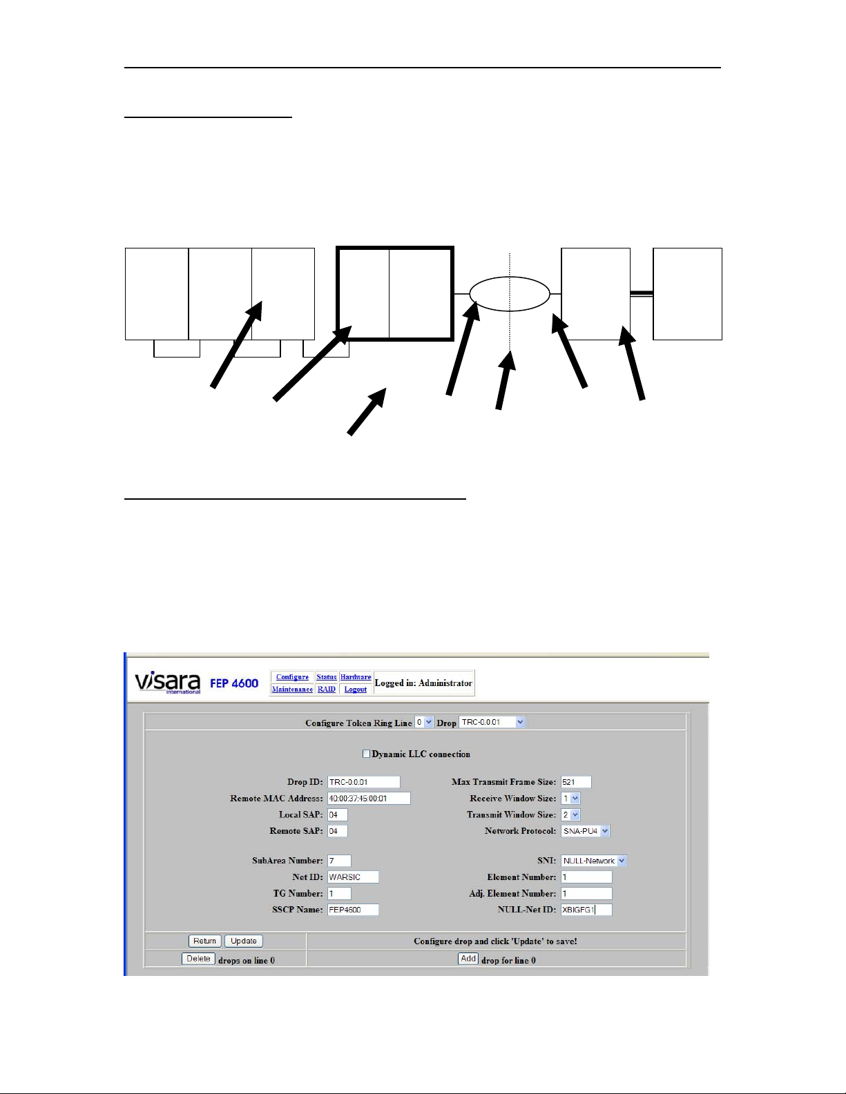
FEP-4600 Installation and Configuration
PU 4 Interface Options
When selecting the Network Protocol to be SNA-PU4, several additional options will be
enabled. Refer to the diagram below to aid in determining the correct values to enter onto
this panel.
CPU FEP-4600
Null Network
3745 CPU
VTAM
1
SA01
SSCP Name
VTAM
SA02
2
Gateway
VTAM
3
SA03
CTC CTC
Element Number
Net ID Option
CTC
VTAM
SA05
Gateway
5
NETID=NET1
NCP
4
SA04
Subarea
Number
Option
SA99SA98
NETID=NULL
NULL-Net ID
Option
NCP
14
SA14
TG Number
VTAM
10
SA10
NETID=NET2
Adj Element
Number
Token Ring Drop Panel for Protocol ‘SNA-PU4’
Pressing the [Drops] button on the Token Ring Line panel causes the Token Ring Drop
panel to display. This panel allows you to define a Token Ring drop that will be
associated with an upstream ESCON Local Major Node definition on the host. By default
the Network Protocol is set to ‘SNA-PU2’. To change this to a PU4 drop definition,
select ‘SNA-PU4’ from the Network Protocol dropdown control. An example of this
panel (SNA-PU4) appears below.
707119-001 5-13
Page 66

Chapter 5. Token Ring Interface
Field Definitions
The options for SNA-PU4 are the same as for SNA-PU2 with the additional parameters
listed below. Also the Dynamic Connection option should not be selected for PU4
connections. Only the options unique to PU4 are listed below.
Net ID: This option corresponds to the NETID used by the local network that the FEP4600 is providing the connection to.
Subarea Number: This represents the subarea number used by the FEP-4600 for the
Token Ring network connection. If there is a Null Network use the Null Subarea number.
TG Number: This number represents the TG number that has been genned into the
remote FEP for the connection between it and the FEP-4600.
SSCP Name: This is the name assigned to the adjacent (ESCON-attached) VTAM.
SNI: This option describes the SNI function that this connection is to perform. Options
are:
None: No SNI is being performed or the SNI is being handled entirely by a
remote NCP.
Single Sided: The FEP-4600 is replacing the Gateway NCP in a single sided SNI
network connection. (The remote NCP is not configured as a Gateway NCP.)
Null SNI: The FEP-4600 is to participate in a Null SNI network connection.
Element Number: This is the Element Number that the FEP-4600 is using to represent
itself to the remote NCP. Normally this would default to Element 1 for the NCP that the
FEP-4600 is replacing. The actual number may not show up in the remote NCP gen if the
default is being used.
Adj. Element Number: This is the Element Number used by the remote front end that
the FEP-4600 is communicating with. Again, this value is most often configured to be 1,
but should match what was previously genned in the NCP that the FEP-4600 is replacing.
NULL-Net ID: This parameter should represent the value configured for the NULL
network if NULL SNI is selected, or should refer to the remote Network NETID if
single-sided SNI is configured.
5-14 707119-001
Page 67

FEP-4600 Installation and Configuration
Button Definitions
Return: Pressing this button will return you back to the ‘Configure Token Ring Line’
panel.
Update: Selecting the Update button will save the current values. If there is a value in
error, an error message will display to the right of the buttons to inform you of the
problem.
Delete: Pressing the Delete button will cause a new panel with the currently defined
Drops listed, to allow you to delete one or more of them. Refer to the Deleting Token
Ring Drops section below.
Add: Pressing this button will cause the fields to display their defaults and display the
next drop number. Make the configuration changes needed for the new drop, then press
the Update button to save the information.
707119-001 5-15
Page 68
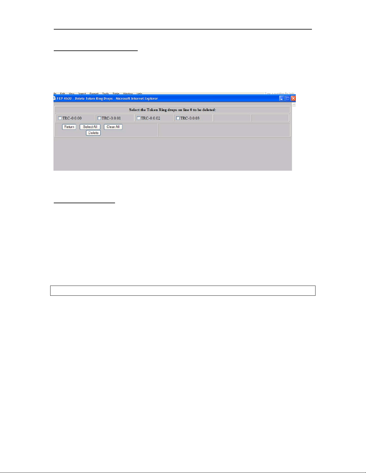
Chapter 5. Token Ring Interface
Deleting Token Ring Drops
When pressing the Delete button on the Configure Token Ring Drops panel, a new panel
will be displayed with the currently configured Drops listed. An example of what this
panel looks like is displayed below.
Select one or more of the listed drops then press the Delete button.
Button Descriptions
Return: Pressing this button will return you to the Configure Token Ring Drops panel.
Select All: When pressing the Select All button, all of the displayed Drops will get
selected.
Clear All: Pressing the Clear All button will deselect any selected Drops.
Delete: Pressing the Delete button will cause a message to display:
You are about to delete the selected drops on line 0. Are you sure you want to do this?
Pressing the OK button will complete the deletion. Pressing the Cancel button will abort
the deletion.
5-16 707119-001
Page 69
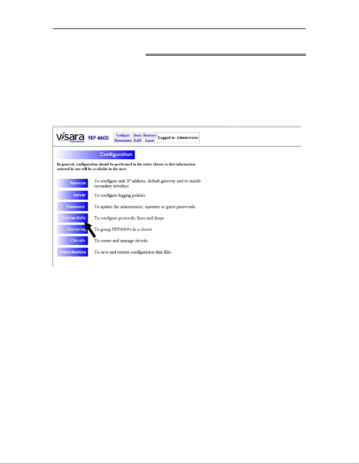
FEP-4600 Installation and Configuration
Chapter 6. Ethernet Interface
The Ethernet interface should be configured after the ESCON interfaces are configured
and prior to configuration of the circuits.
To configure the Ethernet interface, select ‘Configure’ from the menu at the top of most
panels, to display the Configuration menu as shown below.
Select ‘Connectivity’ to display the Connectivity Configuration menu as shown below.
707119-001 6-1
Page 70
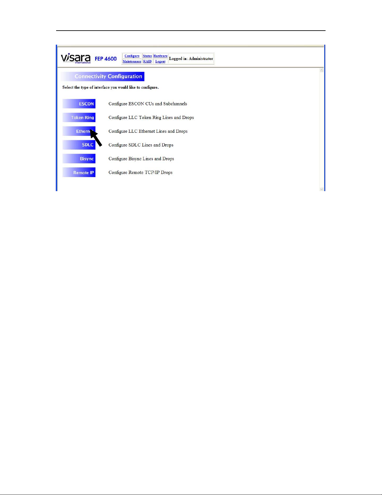
Chapter 6. Ethernet Interface
From this menu, you will need to select the Ethernet option.
6-2 707119-001
Page 71
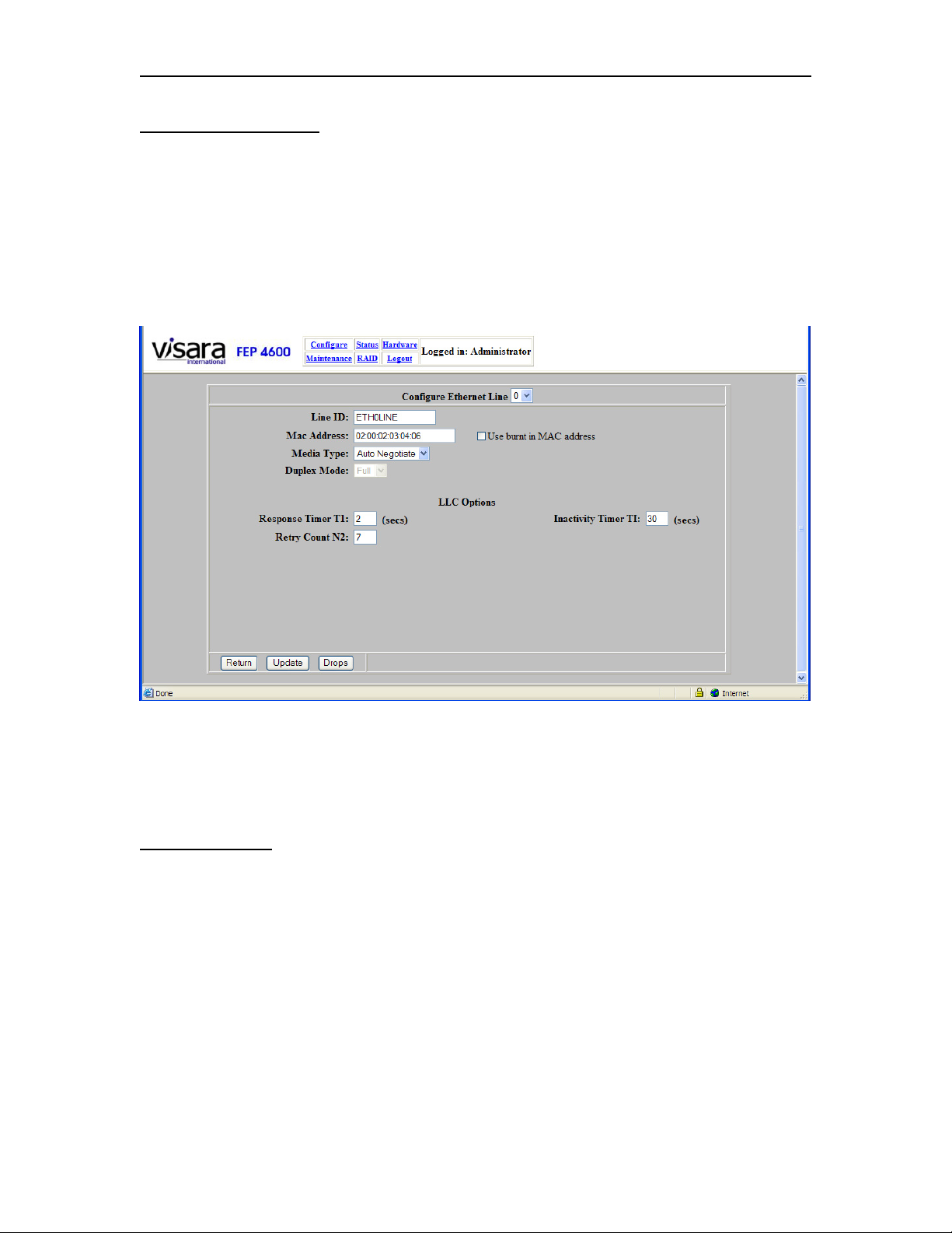
FEP-4600 Installation and Configuration
Ethernet Line Options
The Ethernet configuration for SNA traffic on the FEP-4600 is performed in two steps.
The first step is to configure the Ethernet Line Options, which define the way the
Ethernet interface will interact with the network to which it will be attached. The second
step is to configure the interface to each drop on the Ethernet that the FEP-4600 must
communicate with.
The Ethernet Line Configuration panel appears below.
Changes can be made to the options found on this panel, then press the Update button to
save the changes. Descriptions of the options found on the ‘Ethernet Line Options’ panel
are discussed below:
Field Definitions
Configure Ethernet Line - This option identifies which line you are about to configure.
If you find that you have selected the wrong line, you can select the correct Ethernet line
from the drop down control.
Line ID - This option allows you to apply a name to the Ethernet interface (valid
characters are alphanumeric plus underscore, dash, and period).
MAC Address – Changing the value for this parameter, causes the FEP-4600 to override
the burned in MAC address of the Ethernet interface installed, with the address that you
configure. Be careful not to configure duplicate MAC addresses on your network.
707119-001 6-3
Page 72

Chapter 6. Ethernet Interface
Duplicating a MAC address may cause one or both platforms to stay off the network, or
could cause other errors. The selection of this address is important.
If the FEP-4600 is replacing an existing 37x5 FEP or a Token Ring gateway product, the
downstream platforms that are communicating to that product, include in their
configurations the Token Ring address of that gateway/FEP product. To avoid having to
reconfigure all of those platforms, you may want to set the Ethernet address of the FEP4600 to that same address. You can not typically however, replace a Token Ring address
directly with the same address on an Ethernet card. This is due to Ethernet and Token
Ring designating the high order bit in complete opposition to each other. You must
therefore convert the existing Token Ring address to an Ethernet address using a bit
swapping algorithm. Refer to the section discussing ‘Bit-Swapping LAN Addresses’
below.
Selecting a MAC Address of ‘00:00:00:00:00:00’ will cause the Ethernet interface to use
the burned in address associated with the board itself. This is not recommended. Since
downstream platforms are configured for the MAC address of this unit, replacing the
board in the FEP-4600 would require reconfiguration of all downstream units. Any other
address entered will be used to override the burned in address. Traditionally, locally
administered Ethernet addresses use the format 02:00:xx:xx:xx:xx, where ‘x’ can be any
valid hex digit.
Note that you can not attach the FEP-4600 to the same Ethernet as the platform you are
replacing (or the same bridged Token Ring) and have them powered on at the same time
if you have duplicate addresses. (If you have a duplicate address situation, the FEP-4600
will stay off the Ethernet.) If you want to conduct tests where the FEP-4600 has the same
address as the platform it is replacing, you must ensure that both platforms are not
powered on and connected to the same network at the same time.
Media Type: For the media type option you can configure the Ethernet interface to auto
negotiate the media type and duplex (default) or you can preset it to one of the supported
speeds. The full set of values for this option are:
• Auto Negotiate
• 10 Mbit
• 100 Mbit
• 1 Gbit
Duplex Mode: This option indicates whether the Ethernet will be operating in Full
Duplex or Half Duplex mode. Note that 1 Gbps Ethernet always operates in Full Duplex
mode and if you set ‘Auto Negotiate’, the duplex option will be determined by the
negotiation.
Use Burnt in MAC Address: Checking this box will cause the card to display and use
the MAC address that was burned into the card by the manufacturer at the factory.
Response Timer T1: The value for this timer is an indication of how long the FEP-4600
should wait for an LLC response to a frame before attempting a retry. Commonly used
values would be:
6-4 707119-001
Page 73

FEP-4600 Installation and Configuration
• 2 Seconds (Default) used for LAN connections
• 3 Seconds typically used for WAN connections over leased lines
• 10 Seconds suggested value for WAN connections over Frame Relay
Retry Count N2: The value for this option determines how many attempts will be made
to retry sending a frame at the LLC level, before declaring that an LLC timeout has
occurred. The default value for this option is 7.
Inactivity Timer TI: This option determines how long the FEP-4600 should wait to
attempt to test the interface when there is no activity. A typical value for this parameter is
30 seconds.
Button Definitions
Return: Pressing the Return button takes you back to the previous panel.
Update: Pressing the Update button will save the current values. If there is a value in
error, a message will display to the right of the buttons to alert you to the error situation,
and the values will not be saved.
Drops: Selecting the Drops button will display the Ethernet Drops panel to allow you to
edit the configurations of currently defined drops, and allow you to define new drops.
707119-001 6-5
Page 74

Chapter 6. Ethernet Interface
Bit-Swapping LAN Addresses
Whenever you have a cross media LAN circuit connection between Ethernet and Token
Ring, you will probably need to bit-swap the LAN addresses to complete your
configuration. This is because of the way the address is identified between the two media.
The low order bit designation is opposite between the two LAN media. That is, the most
significant bit in one media is the least significant bit in the other media. This only
becomes an issue when you are entering the LAN addresses that you need as part of the
configuration.
The address that you enter for your media is always correct for your media, but if you are
referencing the address of another platform that is attached to the other media, then you
must reference the bit swapped version of that address. (For example the FEP-4600 is
attached to a Token Ring and the DSPU is attached through an LLC bridge on Ethernet.)
Following you will find an example of a procedure you can use to bit swap an address.
For the example, we will bit-swap the Token Ring address 40:00:37:45:00:16 to the
equivalent that would be seen on an Ethernet drop.
Bit swapping is performed on a byte by byte basis. Separating the address into individual
bytes, we end up with:
40 00 37 45 00 16
which translates to the binary representation of:
01000000 00000000 00110111 01000101 00000000 00010110
Now if we swap the bits of each byte we will have:
00000010 00000000 11101100 10100010 00000000 01101000
Now displaying the resulting hex values again we have:
02 00 EC A2 00 68
And bringing it back together : 02:00:EC:A2:00:68
So the bit-swapped version of 40:00:37:45:00:16 is 02:00:EC:A2:00:68.
Locally administered addresses for a Token Ring environment will normally begin with
4000…. and for the Ethernet environment 0200….. So, for a configuration for the
Ethernet interface, both the local address of the Ethernet card and the address of a remote
Token Ring box, both addresses will typically begin with 0200….., and if the same
configuration were to be implemented on a Token Ring interface, both addresses will
typically begin with 4000….
6-6 707119-001
Page 75
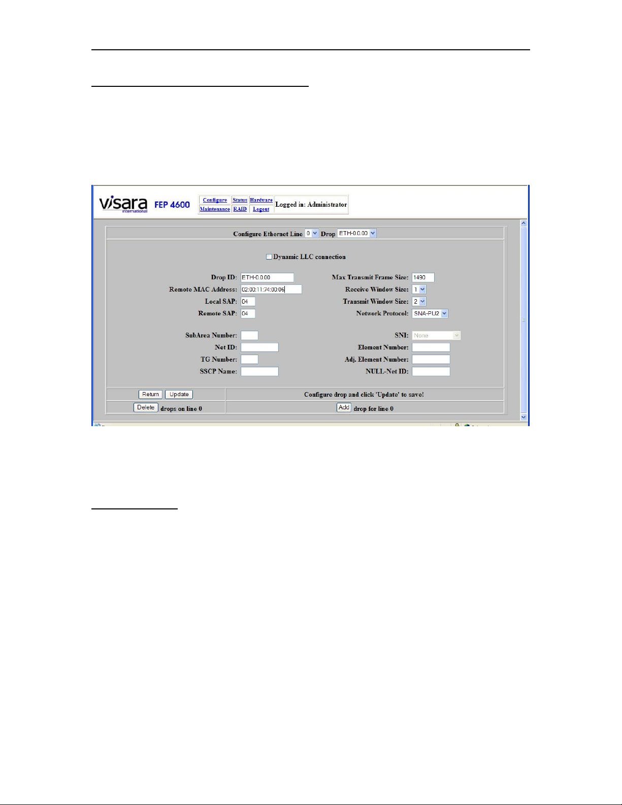
FEP-4600 Installation and Configuration
Ethernet Drop Panel Protocol ‘SNA-PU2’
Pressing the [Drops] button on the Ethernet Line Options panel causes the Ethernet Drop
panel to display. This panel allows you to define an Ethernet drop that will be associated
with an upstream ESCON Local Major Node definition on the host. An example of this
panel (PU2 Drop) appears below.
Many of the displayed options will be unavailable when selected for a protocol of ‘SNAPU2’. An explanation of the available options found on the Drop panel can be found
below:
Field Definitions
Configure Ethernet Line - This option allows you to specify a different Ethernet line, if
the one that is currently selected is not the one that you wish to make changes to.
Drop - This field displays a list of names given to drops that have been defined thus far
by the administrator. As each new drop is defined, it will be added to the list.
Dynamic LLC Connection: When this box is checked, this definition will be used for
dynamic connections. When a remote station connects, it will be challenged for its SNA
XID (PUID). This XID will be used to dynamically connect the station to an upstream
ESCON subchannel that is configured to match the XID (PUID). Selecting Dynamic
LLC will force the remote MAC address in the configuration to ’00:00:00:00:00:00’ and
gray out the ‘Remote MAC Address’ and ‘Remote SAP’.
707119-001 6-7
Page 76

Chapter 6. Ethernet Interface
Drop ID - The Drop ID is the name that is being given to this drop, and is the same name
that will be added to the list of drops when this definition is saved. The name can be most
any text string (alphanumeric characters plus underscore, dash, and period characters),
and should be created by the administrator to provide a name for the drop that is most
useful to describe what or where it is.
Remote MAC Address - This is the LAN address of the platform that the FEP-4600 is
talking to on this drop. This address might also be referred to as the hardware address, or
LLC address.
Local SAP: This option defines the local Service Access Point address that is assigned
by the FEP-4600 for use for communications with the remote platform. Refer to the ‘SAP
Assignments’ section below for selecting a valid SAP value.
Remote SAP - This option defines the remote Service Access Point address that is
configured on the remote platform that the FEP-4600 is communicating with. Refer to the
‘SAP Assignments’ section in the Token Ring chapter for a discussion on selecting valid
SAP values.
Max Transmit Frame Size - This value represents the maximum size frame (including
TH, RH, and RU) that may be sent in a single packet over the LLC link. Ethernet LLC
circuits are limited to a maximum frame size of 1490. Using a smaller value than what is
supported by the session partner will work, but will result in the transmission of more
packets than if a larger value is set. The minimum size for a PU type 2 is 265. The default
value for this option is 521.
Receive Window Size - This is the maximum number of packets in an LLC conversation
with a session partner that can be received, before an LLC acknowledgement must be
sent. The default value for this option is 1. Refer to the ‘Window Size Selection’ section
in the Token Ring chapter.
Transmit Window Size - This is the maximum number of packets that will be sent
before requiring an LLC acknowledgement. The default value for this option is 2. Refer
to the ‘Window Size Selection’ section in the Token Ring chapter.
Network Protocol – You must select which protocol the FEP-4600 is to use when
communicating with the remote station over this circuit. The options are:
• SNA-PU2 – Use this when the remote platform is a PU 2 control unit or PC
emulating a PU type 2, and the host definition is part of a Local Major Node.
• SNA-PU4 – Use this selection when the remote platform is a 37x5 Front End or
another FEP-4600.
• XCA – Use this value when the remote platform is a PU 2 platform and the host
definition is part of a Switched Major Node definition.
6-8 707119-001
Page 77

FEP-4600 Installation and Configuration
Button Definitions
Return: Selecting this button will return you to the ‘Update ESCON CU’ panel.
Update: Selecting the ‘Update’ button will save any changes that you have made on this
panel. A message indicating ‘Subchannel update complete!’ should display.
Delete: Pressing this button will bring up the Delete Drops panel.
Add: Pressing this button will add a new Drop definition and set several of the options
to default values. You must remember to press the [Update] button when you are finished
modifying the values to save the new drop information.
707119-001 6-9
Page 78
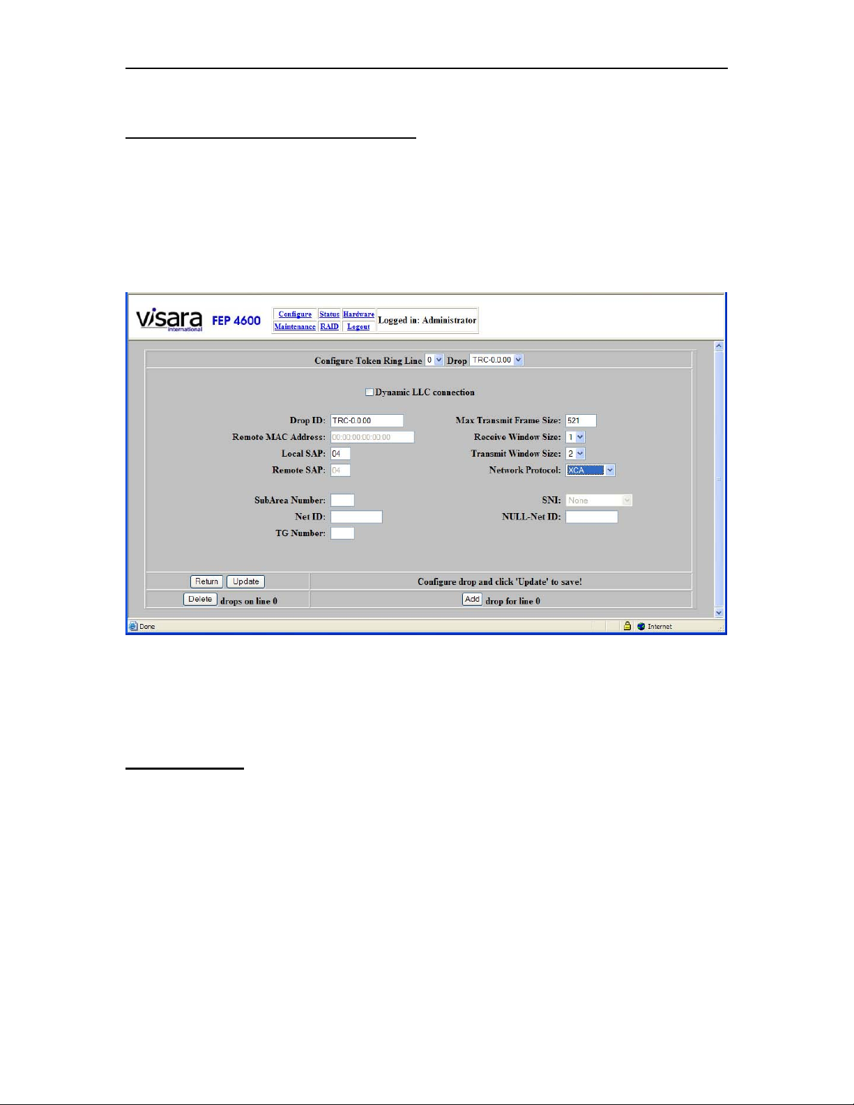
Chapter 6. Ethernet Interface
Ethernet Drop Panel for Protocol ‘XCA’
Pressing the [Drops] button on the Ethernet Line panel causes the Ethernet Drop panel to
display. By default the Network Protocol is set to ‘SNA-PU2’. To change this to an XCA
definition, select ‘XCA’ from the Network Protocol dropdown control. An XCA
definition is matched in the FEP-4600 configuration to an ESCON XCA definition. This
allows network attached PU2 devices to communicate to Switched Major Node PU2
definitions on the host. An example of this panel (XCA Drop) appears below.
Although many parameters are displayed, most are not used by XCA and cannot be
defined or changed. An explanation of the valid options for XCA found on the Drop
panel can be found below:
Field Definitions
Configure Ethernet Line: This option allows you to specify a different Ethernet line, if
the one that is currently selected is not the one that you wish to make changes to.
Drop: This field displays a list of names given to drops that have been defined thus far
by the administrator. As each new drop is defined, it will be added to the list.
Drop ID: The ‘Drop ID’ is the name that is being given to this drop, and is the same
name that will be added to the list of drops when this definition is saved. The name can
be most any text string (alphanumeric characters plus dash, underscore, and period
characters), and should be created by the administrator to provide a name for the drop
that is most useful to describe what or where it is.
6-10 707119-001
Page 79

FEP-4600 Installation and Configuration
Local SAP: This option defines the local Service Access Point address that is assigned
by the FEP-4600 for use for communications with the remote platform. Refer to the ‘SAP
Assignments’ section above for selecting a valid SAP value. When defining XCA drops
on the same interface used for SNA-PU4 and SNA-PU2 drops, you must assign a
different SAP for use by XCA than for use by the other functions.
Max Transmit Frame Size: This value represents the maximum size frame (including
TH, RH, and RU) that may be sent in a single packet over the LLC link. The minimum
size for a PU type 2 is 265. The default value for this option is 521. The maximum value
must be restricted to that handled by Ethernet (a value of 1490).
Receive Window Size: This is the maximum number of packets in an LLC conversation
with a session partner that can be received, before an LLC acknowledgement must be
sent. The default value for this option is 1. Refer to the ‘Window Size Selection’ section
below.
Transmit Window Size: This is the maximum number of packets that will be sent
before requiring an LLC acknowledgement. The default value for this option is 2. Refer
to the ‘Window Size Selection’ section below.
Network Protocol – You must select which protocol the FEP-4600 is to use when
communicating with the remote station over this circuit. The options are:
• SNA-PU2 – Use this when the remote platform is a PU 2 control unit or PC
emulating a PU type 2, and the host definition is part of a Local Major Node.
• SNA-PU4 – Use this selection when the remote platform is a 37x5 Front End or
another FEP-4600.
• XCA – Use this value when the remote platform is a PU 2 platform and the host
definition is part of a Switched Major Node definition.
Button Definitions
Return: Selecting this button will return you to the ‘Update ESCON CU’ panel.
Update: Selecting the ‘Update’ button will save any changes that you have made on this
panel. A message indicating ‘Subchannel update complete!’ should display.
Delete: Pressing this button will bring up the Delete Drops panel.
Add: Pressing this button will add a new Drop definition and set several of the options
to default values. You must remember to press the [Update] button when you are finished
modifying the values to save the new drop information.
707119-001 6-11
Page 80
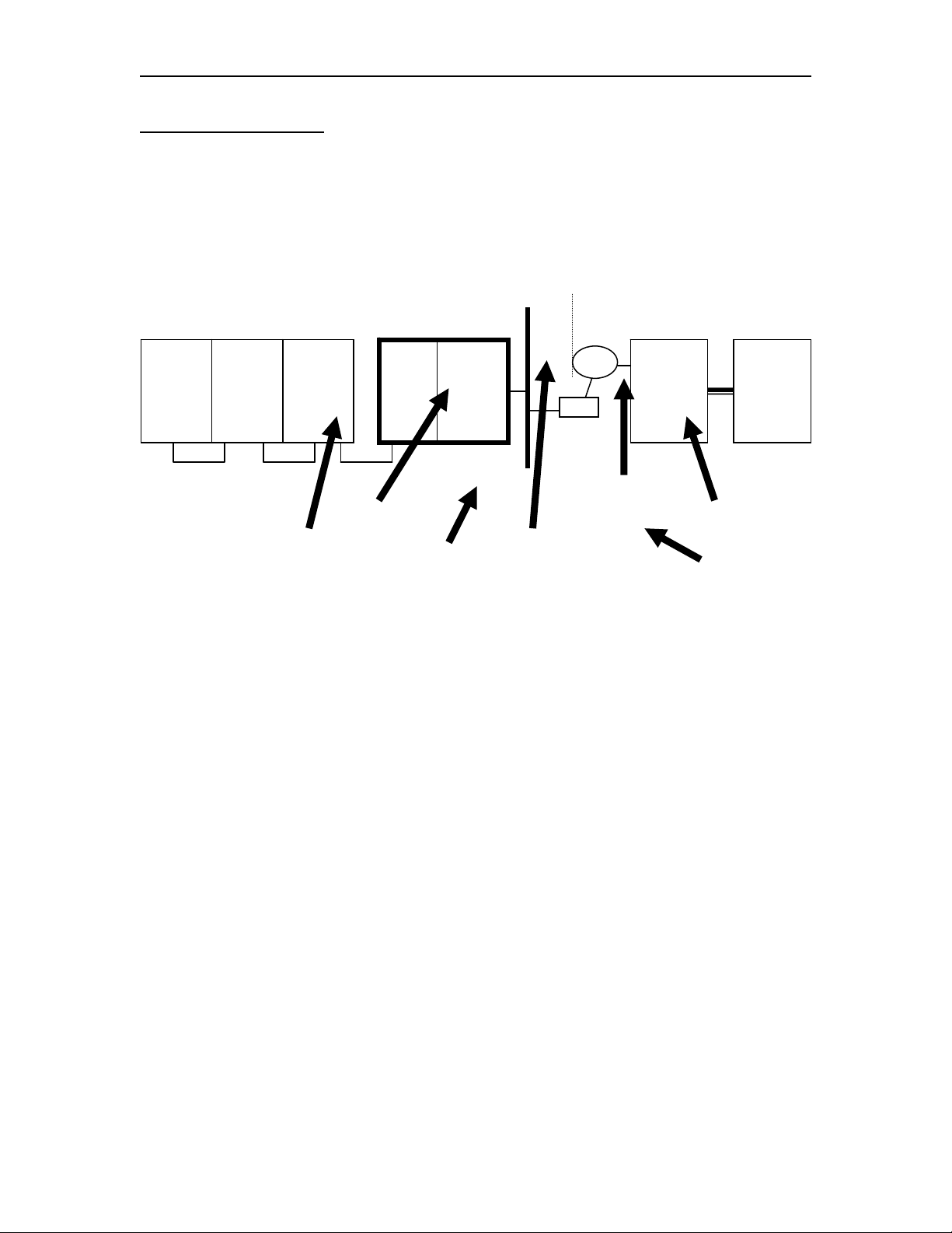
Chapter 6. Ethernet Interface
PU 4 Interface Options
The following options only apply to PU4 interfaces. You may reference the diagram
below to help identify what should be configured for these options.
Null Network
CPU FEP-4600
VTAM
1
SA01
VTAM
2
SA02
CTC CTC
SSCP Name Subarea
Gateway
VTAM
3
SA03
CTC
VTAM
NETID=NET1
Net ID
Option
Gateway
NCP
4
SA04
Number
Option
SA99SA98
LLC
Bridge
TG Number
NETID=NULL
3745 CPU
Gateway
NCP
14
SA14
Gateway
VTAM
10
SA10
NETID=NET2
Adj. Element NumberElement Number
NULL Net ID Option
6-12 707119-001
Page 81
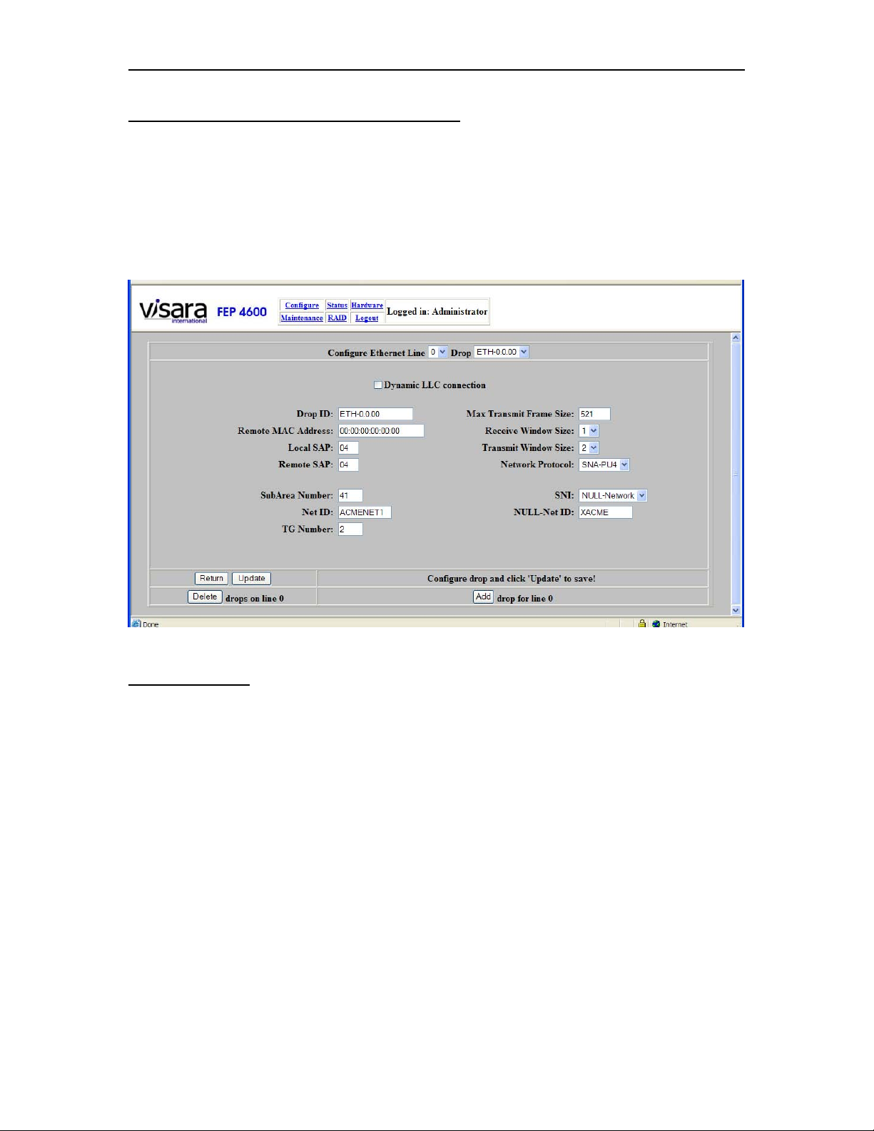
FEP-4600 Installation and Configuration
Ethernet Drop Panel for Protocol ‘SNA-PU4’
Pressing the [Drops] button on the Ethernet Line panel causes the Ethernet Drop panel to
display. This panel allows you to define an Ethernet drop that will be associated with an
upstream ESCON Local Major Node definition on the host. By default the Network
Protocol is set to ‘SNA-PU2’. To change this to a PU4 drop definition, select ‘SNA-PU4’
from the Network Protocol dropdown control. An example of this panel (SNA-PU4)
appears below.
Field Definitions
The options for SNA-PU4 are the same as for SNA-PU2 with the additional parameters
listed below. Also the Dynamic Connection option should not be selected for PU4
connections. Only the options unique to PU4 are listed below.
Net ID: This option corresponds to the NETID used by the foreign network that the
FEP-4600 is providing the connection to.
Subarea Number: This represents the subarea number used by the FEP-4600 as it
would appear to the remote NCP (use the Null Network subarea if a Null Network
definition is in place).
TG Number: This number represents the TG number that has been genned into the
remote FEP for the connection between it and the FEP-4600.
SSCP Name: This is the name assigned to the adjacent (ESCON-attached) VTAM.
707119-001 6-13
Page 82

Chapter 6. Ethernet Interface
SNI: This option describes the SNI function that this connection is to perform. Options
are:
None: No SNI is being performed or the SNI is being handled entirely by a
remote NCP.
Single Sided: The FEP-4600 is replacing the Gateway NCP in a single sided SNI
network connection.
Null SNI: The FEP-4600 is to participate in a Null SNI network connection.
Element Number: This is the Element Number that the FEP-4600 is using to represent
itself to the remote NCP. Normally this would default to Element 1 for the NCP that the
FEP-4600 is replacing. The actual number may not show up in the remote NCP gen if the
default is being used.
Adj. Element Number: This is the Element Number used by the remote front end that
the FEP-4600 is communicating with. Again, this value is most often configured to be 1,
but should match what was previously genned in the NCP that the FEP-4600 is replacing.
NULL-Net ID: This parameter should represent the value configured for the NULL
network if NULL SNI is selected, or should refer to the remote Network NETID if
single-sided SNI is configured.
Button Definitions
Return: Pressing this button will return you back to the ‘Configure Ethernet Line’ panel.
Update: Selecting the Update button will save the current values. If there is a value in
error, an error message will display to the right of the buttons to inform you of the
problem.
Delete: Pressing the Delete button will cause a new panel with the currently defined
Drops listed, to allow you to delete one or more of them. Refer to the Deleting Ethernet
Drops section below.
Add: Pressing this button will cause the fields to display their defaults and display the
next drop number. Make the configuration changes needed for the new drop, then press
the Update button to save the information.
6-14 707119-001
Page 83
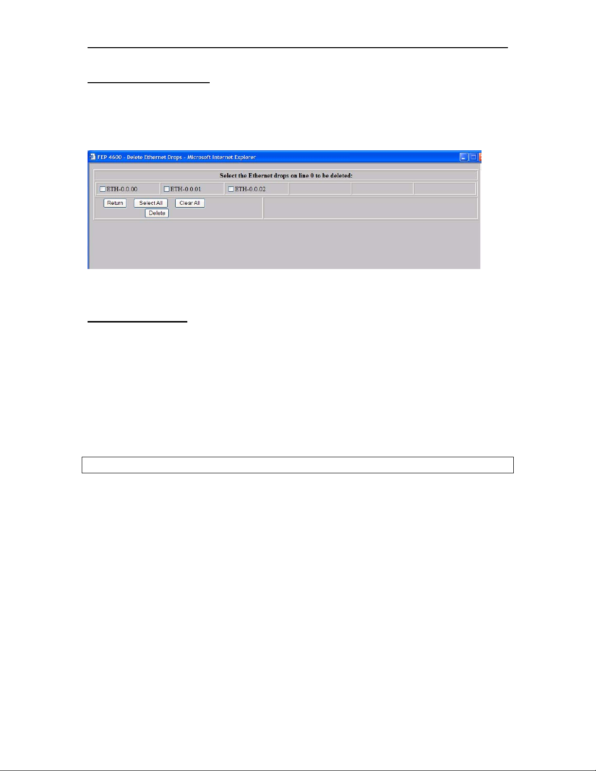
FEP-4600 Installation and Configuration
Deleting Ethernet Drops
When pressing the Delete button on the Configure Ethernet Drops panel, a new panel will
be displayed with the currently configured Drops listed. An example of what this panel
looks like is displayed below.
Select one or more of the listed drops then press the Delete button.
Button Descriptions
Return: Pressing this button will return you to the Configure Ethernet Drops panel.
Select All: When pressing the Select All button, all of the displayed Drops will get
selected.
Clear All: Pressing the Clear All button will deselect any selected Drops.
Delete: Pressing the Delete button will cause a message to display:
You are about to delete the selected drops on line x. Are you sure you want to do this?
Pressing the OK button will complete the deletion. Pressing the Cancel button will abort
the deletion.
707119-001 6-15
Page 84

Chapter 6. Ethernet Interface
6-16 707119-001
Page 85
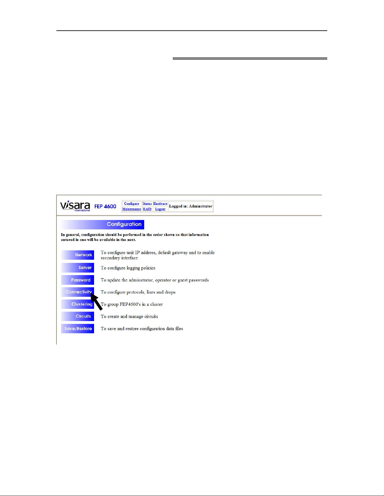
FEP-4600 Installation and Configuration
Chapter 7. SDLC Interface
The SDLC interfaces should be configured after the ESCON interfaces are configured
and prior to configuration of the circuits.
SDLC interfaces are provided on the FEP-4600 through one or more QSA (Quad Serial
Adapters). To support SDLC attached platforms on the FEP-4600, it will be necessary to
customize the configuration. Configuration for SDLC is conducted in two parts. The first
part is to configure the common Line Options used by all platforms communicating over
a particular line. The second part is to configure the Drop Options. Each platform
communicating over the line will have a separate set of Drop Options.
To configure the SDLC interface, select ‘Configure’ from the menu at the top of most
panels, to display the Configuration menu as shown below.
Select ‘Connectivity’ to display the Connectivity Configuration menu as shown below.
707119-001 7-1
Page 86
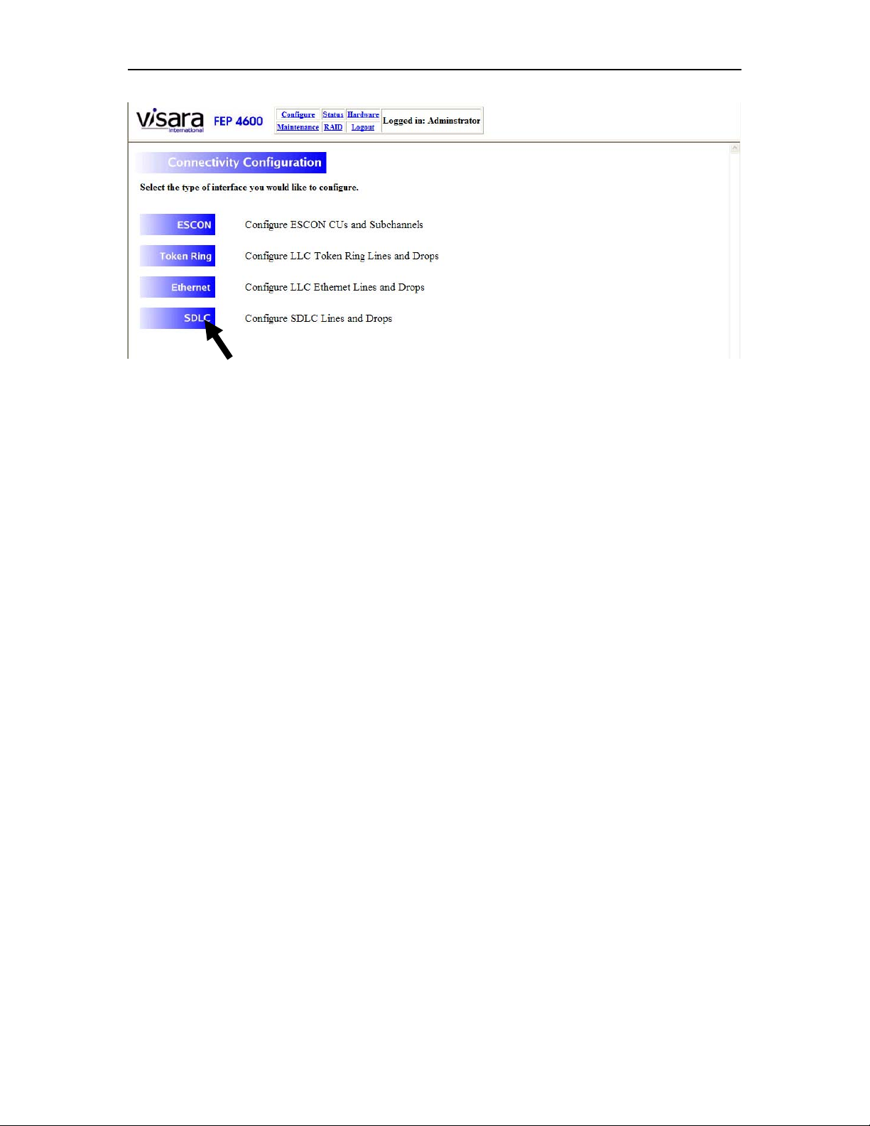
Chapter 7. SDLC Interface
From this menu, you will need to select the SDLC option.
7-2 707119-001
Page 87
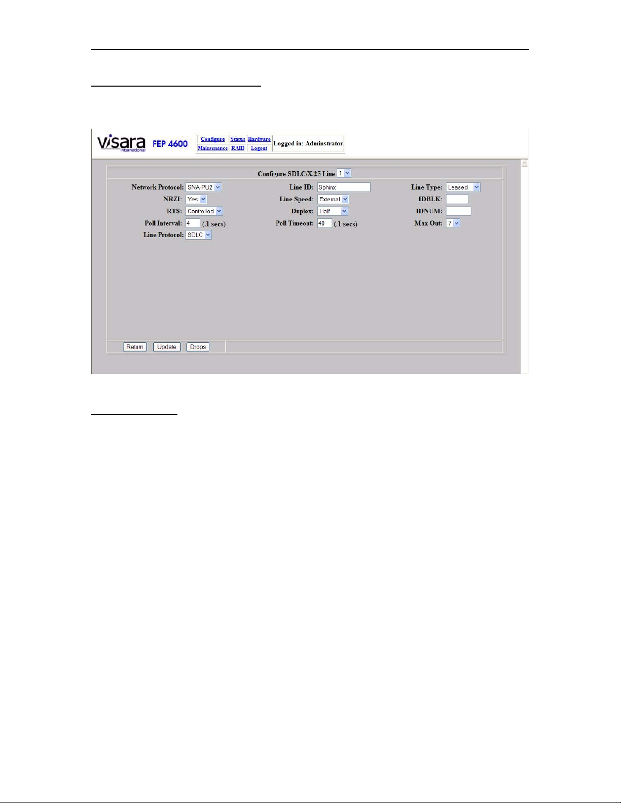
FEP-4600 Installation and Configuration
Configuring SDLC Line Options
When you select to configure a line (for SDLC) the following panel will be displayed.
Field Definitions
Configurable options for SDLC include:
Network Protocol: This option indicates whether the platform we are communicating
with is a PU type 2.0, PU type 2.1, or PU type 4.
NRZI: Set to ‘Yes’, NRZI option will be used. When set to ‘No’, NRZ will be used
instead.
RTS: When set to ‘Constant’ the Request to Send (RTS) signal will be kept high. This
option is the preferred option if you are using a 4-wire circuit, since the FEP-4600 will
not have to wait for Clear to Send (CTS) to be offered. If you are using a 2-wire circuit,
you must set this option to ‘Controlled’. When set to ‘Controlled’ the RTS signal will be
brought active only when the FEP-4600 needs to transmit data. If you are having
difficulty getting a new circuit to work, set this option to ‘Controlled’, since it will work
in 2-wire and 4-wire situations, until you are confident that the circuit is 4-wire.
Poll Interval: The poll interval indicates the minimum amount of time between the start
of each poll cycle. A timer begins at the start of a poll cycle, and if the cycle is completed
and the interval has not been met, then the FEP-4600 will wait until the interval lapses to
begin the next poll cycle.
707119-001 7-3
Page 88

Chapter 7. SDLC Interface
Line Protocol: This option allows you to select between SDLC and X.25. For a
description of configuring the X.25 interface see the chapter on X.25.
Line ID: This is a text field (alphanumeric plus underscore, dash, and period) that you
can enter a description for the line to make it more recognizable for management
purposes.
Line Speed: Most lines will be configured for ‘External’, indicating that a modem or
modem eliminator is to be attached that will provide the clocking for the circuit. If no
modem or modem eliminator are to be used, then you will need to set this option to one
of the clocking speeds provided in the drop down. The QSA card provides the clocking
signal for SDLC interfaces. This option is normally used in coordination with using a
DCE cable for direct attachment to the platform that the FEP-4600 is communicating
with. Supported clocking speeds are:
• 4800 bps
• 9600 bps
• 14,400 bps
• 19,200 bps
• 56,000 bps
• 64,000 bps
• 128,000 bps
• T1 (1.544 Mbps) speed
• E1 (2.0 Mbps) speed
Duplex: There are three values for this option:
• Full – RTS is kept active to reduce turnaround time. If you are connected to a 2-
wire circuit, you must not use this setting.
When using this for multi-drop lines, the FEP-4600 does not have to wait for a
response from one drop before a poll is sent to the next drop in the list. The
secondary PUs on the line should be set for Half Duplex. Outbound data takes
priority over polling a drop with no outbound data.
When using this on point-to-point lines, both the FEP-4600 and the secondary
station can be set for Full Duplex
• Half – RTS is switched. The FEP-4600 and the secondary PU(s) take turns
communicating over the line.
For multi-drop lines, each drop is polled in order, regardless of whether there is
outbound data for one of the drops.
• HDXSP – If the FEP-4600 has outbound data, sending the data will take
precedence over a scheduled poll to a drop.
Note: If you are having trouble getting a new circuit up, then set this value to ‘Half’ until
you resolve what is causing the problem. You should also turn off all but one drop on a
multi-drop line, and add more drops one at a time until they all work. If adding a drop
causes problems, check to ensure that the drop is configured to run in Half Duplex mode.
7-4 707119-001
Page 89

FEP-4600 Installation and Configuration
Poll Timeout: This value determines how long the FEP-4600 is to wait for a response
before continuing through the poll list.
Line Type: The options for this are either ‘Leased’ or ‘Switched’. If the remote platform
will be dialing in, then set the Line Type for ‘Switched’. Otherwise set it for ‘Leased’. If
the Line Type is set to Switched, then the remote box should be configured to pass
IDBLK and IDNUM information in the form of an Exchange ID (XID).
IDBLK: This field accepts a 3 hex-character input. See ‘IDBLK and IDNUM Usage’.
IDNUM: This field accepts a 5 hex-character input. See ‘IDBLK and IDNUM Usage’.
Max Out: The FEP-4600 supports Modulo 8 (value of 7).
IDBLK and IDNUM Usage
The IDBLK and IDNUM fields when combined, creates an 8-character (hex) value. This
value is used to match to one of the ESCON CU subchannel address definitions. If the
platform communicating over the SDLC link is configured with its own PUID
information, this information will normally be presented during an XID exchange and is
used to select the upstream ESCON connection. If you wish to override the value
provided by the remote platform, fill in the IDBLK and IDNUM fields with the value you
wish to present. Any configured value should match the PUID field for the ESCON CU
subchannel address definition that you wish to link to.
Button Definitions
Return: Pressing the Return button takes you back to the previous panel.
Update: Pressing the Update button will save the current values. If there is a value in
error, a message will display to the right of the buttons to alert you to the error situation,
and the values will not be saved.
Drops: Selecting the Drops button will display the SDLC Drops panel to allow you to
edit the configurations of currently defined drops, and allow you to define new drops.
707119-001 7-5
Page 90
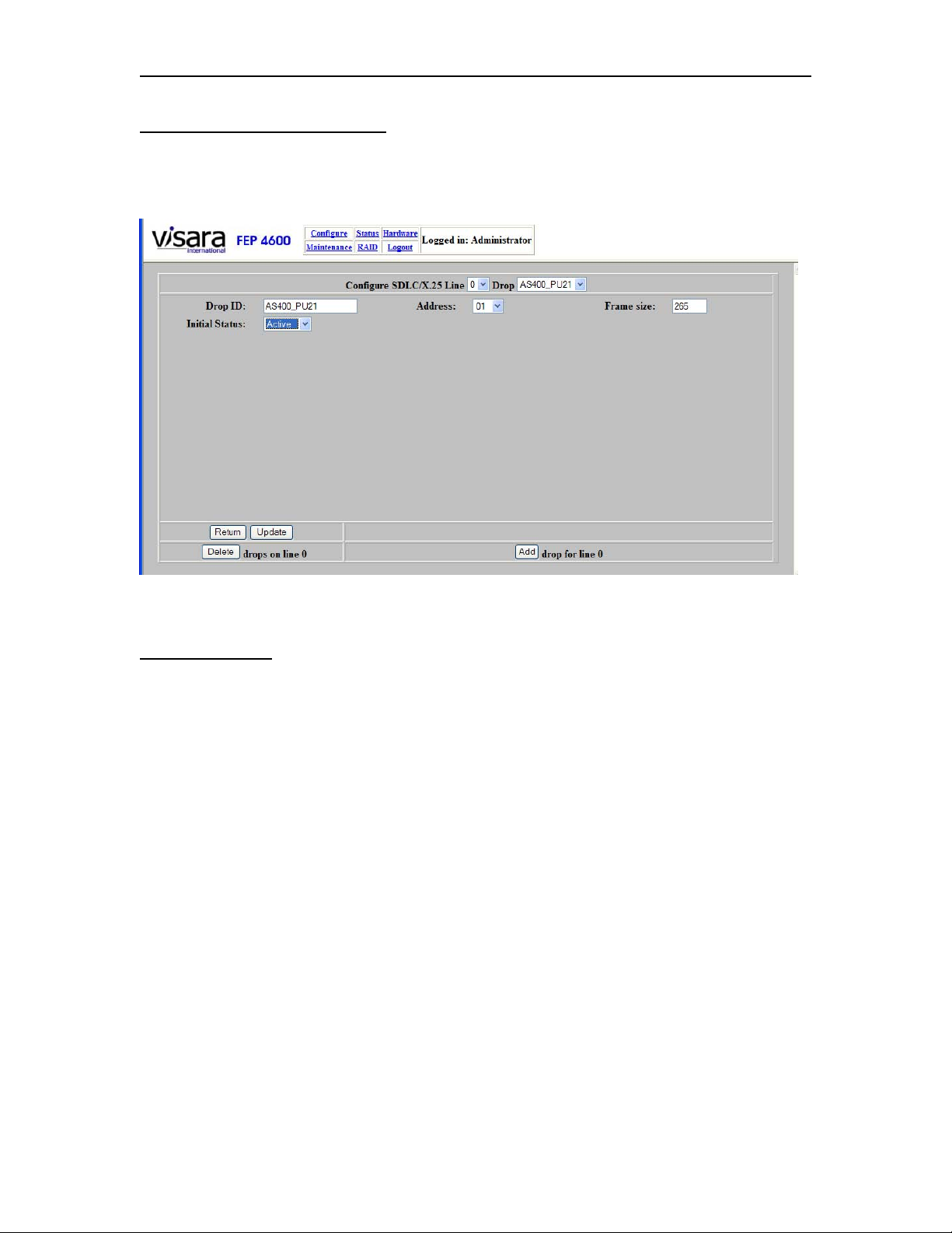
Chapter 7. SDLC Interface
SDLC Drop Panel (PU Type 2)
By selecting the ‘Drops’ button the following SDLC Drop Configuration panel will
display.
The options that may be configured for each drop consists of:
Field Definitions
Line: This defaults to the line that you selected. You can change to a different line to
make changes to.
Drop: This defaults to the Drop that you selected, but you can change the configuration
of a different drop if you wish by selecting another drop from the drop down control.
Undefined Drops are ignored. To add a new drop, select the ’Add’ button at the bottom of
the panel.
Drop ID: This is a text field (alphanumeric plus underscore, dash, and period) that you
can define that will be used in the FEP-4600 panels to allow you to recognize individual
drops better.
Address: This is the hex value (01-FE) that will be used to poll the platform identified
by this Drop. The value entered on this panel must match the configuration of the
platform that is represented by this drop.
Frame Size: This option determines the maximum frame size that will be sent by the
FEP-4600 to the remote platform, and ranges from 265-4105. Common values are:
7-6 707119-001
Page 91

FEP-4600 Installation and Configuration
• 265: This is the default value and the smallest frame size that is allowed. All
SDLC platforms are required to support a frame size of 265. Any 3274 or 3276
compatible platform will support this value.
• 521: This is the commonly supported value for a 3174 compatible platform.
• 4105: This value is supported by some platforms (such as a Visara 1174 HSC
card), and is commonly used for a PU 4 connection to a remote 37x5.
Configure a value that is compatible with the type of platform that is connected. Setting a
larger value than that which is supported by the remote platform will result in receive
overrun errors on the remote platform. If the remote platform is unknown, use the default
value initially.
Initial Status: This option determines whether the FEP-4600 should attempt to poll the
SDLC line whenever the it is powered up. If set to Active, the FEP-4600 will attempt to
poll the drop at the configured interval anytime that the FEP-4600 is up. If set to Inactive,
the FEP-4600 will not attempt to bring up the drop.
Button Definitions
Return: Pressing this button will return you back to the ‘Configure SDLC Line’ panel.
Update: Selecting the Update button will save the current values. If there is a value in
error, an error message will display to the right of the buttons to inform you of the
problem.
Delete: Pressing the Delete button will cause a new panel with the currently defined
Drops listed, to allow you to delete one or more of them. Refer to the Deleting SDLC
Drops section below.
Add: Pressing this button will cause the fields to display their defaults and display the
next drop number. Make the configuration changes needed for the new drop, then press
the Update button to save the information.
707119-001 7-7
Page 92
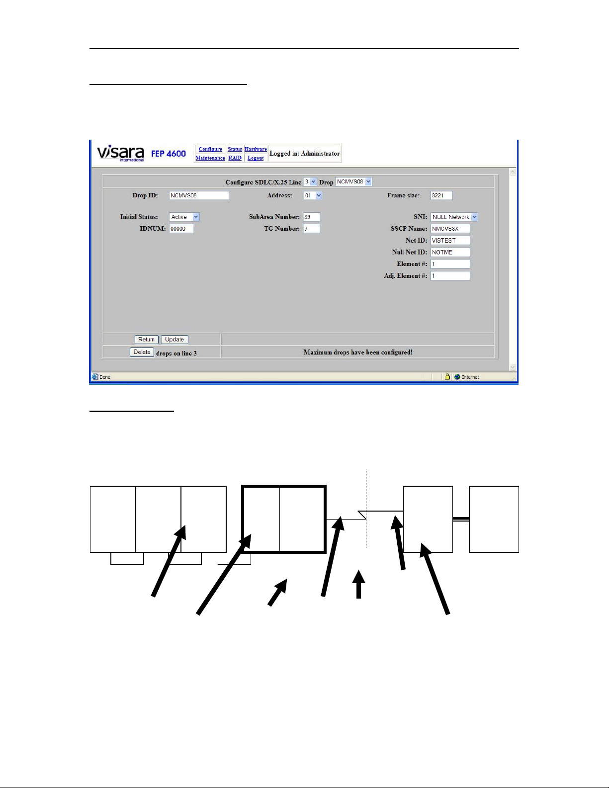
Chapter 7. SDLC Interface
SDLC Drop Panel (PU Type 4)
If the line is defined for use with PU 4, selecting the ‘Drops’ button will result in the
following SDLC Drop Configuration panel.
Field Definitions
PU 4 specific options are described below.
Null Network
CPU FEP-4600
VTAM
1
SA01
VTAM
2
SA02
Gateway
CTC CTC
SSCP Name
VTAM
3
SA03
VTAM
CTC
Net ID Option
NETID=NET1
Gateway
NCP
4
SA04
Subarea
Number
Option
SA99SA98
NETID=NULL
TG Number
NULL-Net ID Option
3745 CPU
Gateway
NCP
14
SA14
NETID=NET2
Adj Element NumberElement Number
Gateway
VTAM
10
SA10
Net ID: This option corresponds to the NETID used by the foreign network that the
FEP-4600 is providing the connection to.
7-8 707119-001
Page 93

FEP-4600 Installation and Configuration
Subarea Number: This represents the subarea number used by the FEP-4600 (use the
Null Subarea number if a Null Subarea is present).
TG Number: This number represents the TG number that has been genned into the
remote FEP for the connection between it and the FEP-4600.
SSCP Name: This is the name assigned to the adjacent (ESCON-attached) VTAM.
SNI: This option describes the SNI function that this connection is to perform. Options
are:
None: No SNI is being performed or the SNI is being handled entirely by a
remote NCP.
Single Sided: The FEP-4600 is replacing the Gateway NCP in a single sided SNI
network connection.
Null SNI: The FEP-4600 is to participate in a Null SNI network connection.
Element Number: This is the Element Number that the FEP-4600 is using to represent
itself to the remote NCP. Normally this would default to Element 1 for the NCP that the
FEP-4600 is replacing. The actual number may not show up in the remote NCP gen if the
default is being used.
Adj. Element Number: This is the Element Number used by the remote front end that
the FEP-4600 is communicating with. Again, this value is most often configured to be 1,
but should match what was previously genned in the NCP that the FEP-4600 is replacing.
NULL-Net ID: This parameter should represent the value configured for the NULL
network if NULL SNI is selected, or should refer to the remote Network NETID if
single-sided SNI is configured.
Button Definitions
Return: Pressing this button will return you back to the ‘Configure Ethernet Line’ panel.
Update: Selecting the Update button will save the current values. If there is a value in
error, an error message will display to the right of the buttons to inform you of the
problem.
Delete: Pressing the Delete button will cause a new panel with the currently defined
Drops listed, to allow you to delete one or more of them. Refer to the Deleting Ethernet
Drops section below.
Add: Pressing this button will cause the fields to display their defaults and display the
next drop number. Make the configuration changes needed for the new drop, then press
the Update button to save the information. Only one drop per PU 4 line is allowed by the
FEP-4600.
707119-001 7-9
Page 94
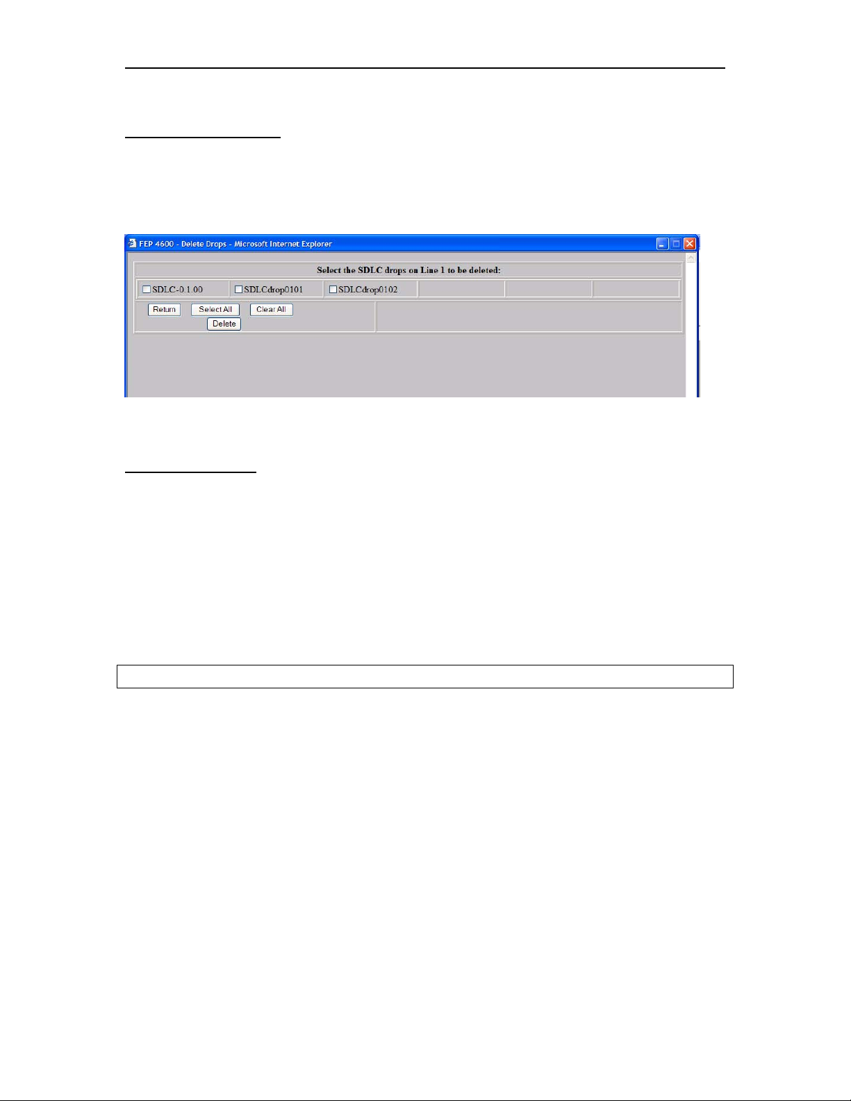
Chapter 7. SDLC Interface
Deleting SDLC Drops
When pressing the Delete button on the Configure SDLC/X.25 Line panel, a new panel
will be displayed with the currently configured Drops listed. An example of what this
panel looks like is displayed below.
Select one or more of the listed drops then press the Delete button.
Button Definitions
Return: Pressing this button will return you to the Configure SDLC Line panel.
Select All: When pressing the Select All button, all of the displayed Drops will get
selected.
Clear All: Pressing the Clear All button will deselect any selected Drops.
Delete: Pressing the Delete button will cause a message to display:
You are about to delete the selected drops on line x. Are you sure you want to do this?
Pressing the OK button will complete the deletion. Pressing the Cancel button will abort
the deletion.
7-10 707119-001
Page 95
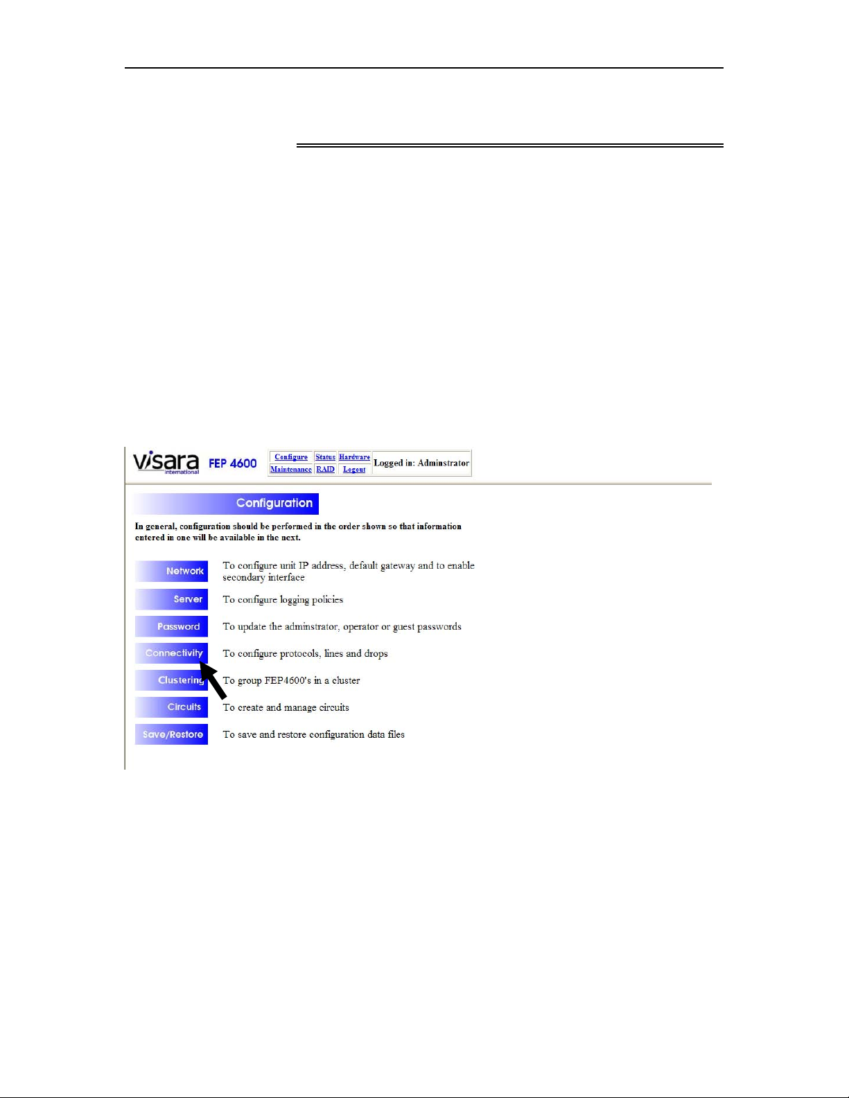
FEP-4600 Installation and Configuration
Chapter 8. 3270 Bisync Interface
The 3270 Bisync interfaces should be configured after the ESCON interfaces are
configured and prior to configuration of the circuits.
Bisync interfaces are provided on the FEP-4600 through one or more QBA (Quad Bisync
Adapters). To support Bisync attached platforms on the FEP-4600, it will be necessary to
customize the configuration. Configuration for Bisync is conducted in two parts. The first
part is to configure the common Line Options used by all platforms communicating over
a particular line. The second part is to configure the Drop Options. Each platform
communicating over the line will have a separate set of Drop Options.
To configure the Bisync interface, select ‘Configure’ from the menu at the top of most
panels, to display the Configuration menu as shown below.
Select ‘Connectivity’ to display the Connectivity Configuration menu as shown below.
707119-001 8-1
Page 96
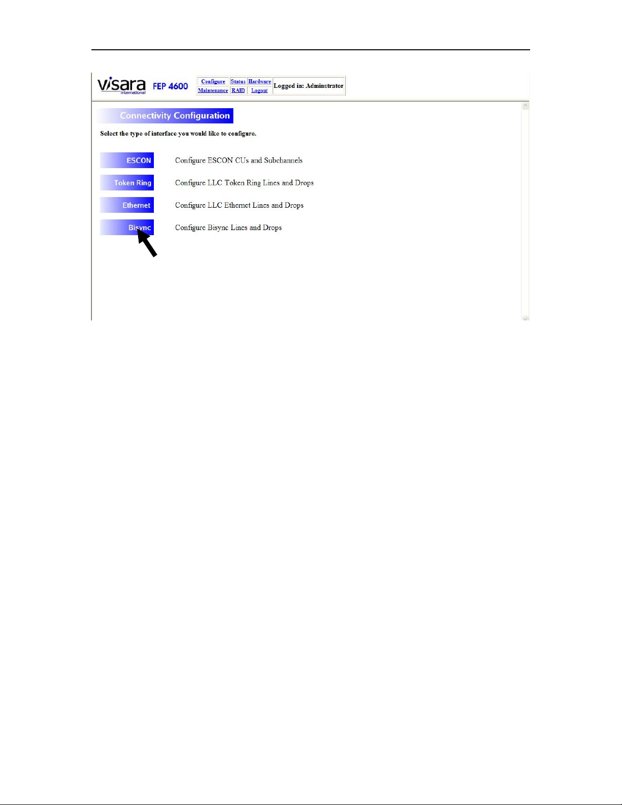
Chapter 8. 3270 Bisync Interface
From this menu, you will need to select the Bisync option.
8-2 707119-001
Page 97
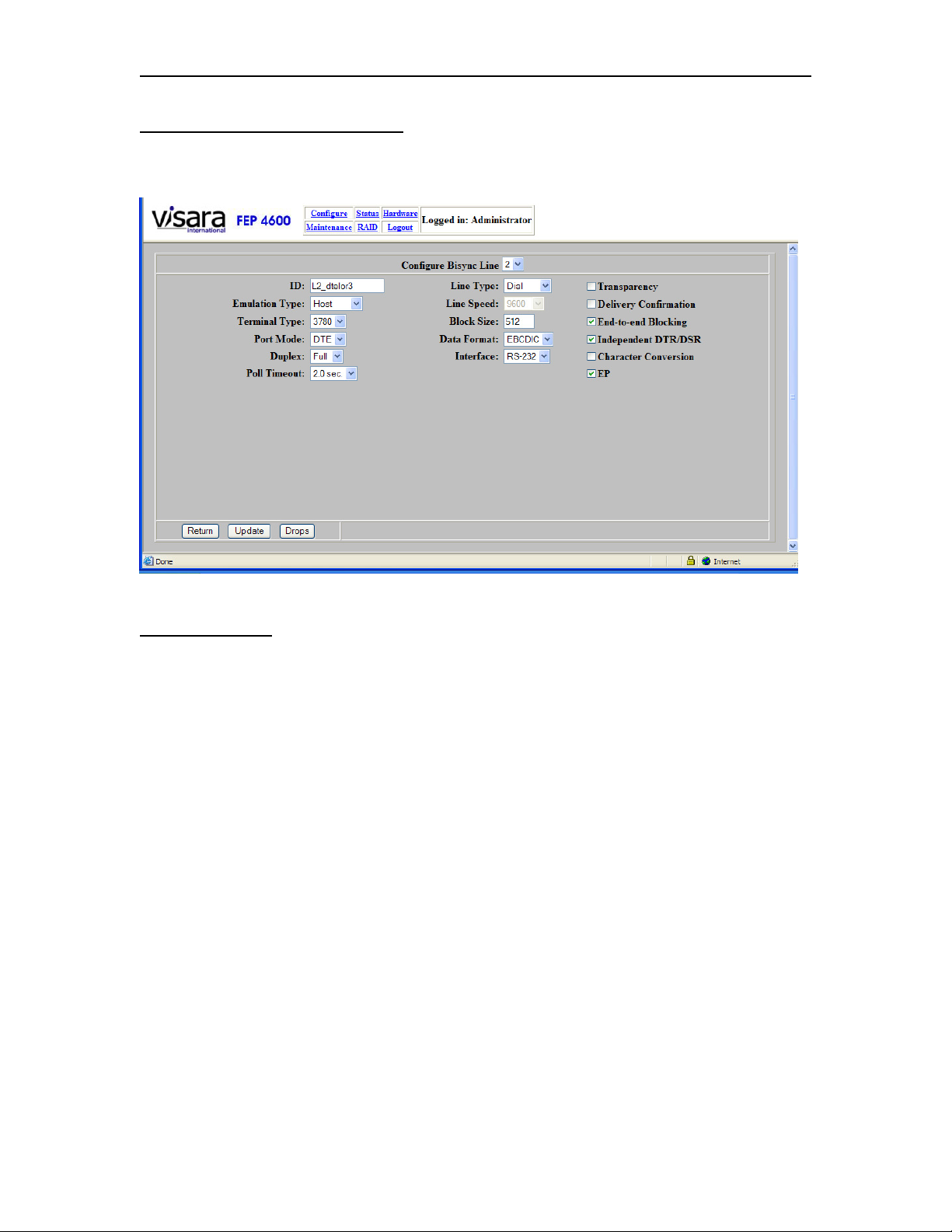
FEP-4600 Installation and Configuration
Configuring Bisync Line Options
When you select to configure a line (for Bisync) the following panel will be displayed.
Field Definitions
Configurable options for Bisync include:
ID: This is a text field (alphanumeric plus underscore, dash, and period) that you can
enter a description for the line to make it more recognizable for management purposes.
Emulation Type: There are two configurable options: Host and Terminal. For 3270
Bisync, only the Host option is valid.
Terminal Type: Configurable terminal types are:
• 2770
• 2780
• 3270 (Only one currently supported)
• 3741
• 3780
Port Mode: Configurable Port Modes are DCE and DTE. DCE or Data Communication
Equipment indicates that the FEP-4600 will be providing clocks as if it were a modem
thus allowing a 3270 Bisync platform to be directly attached. DTE or Data Terminal
Equipment indicates that the FEP-4600 expects to be attached to a modem or modem
eliminator.
Duplex: There are two values for this option:
707119-001 8-3
Page 98

Chapter 8. 3270 Bisync Interface
• Full – RTS is kept active to reduce turnaround time. If you are connected to a 2-
wire circuit, you must not use this setting.
When using this on point-to-point lines, both the FEP-4600 and the secondary
station can be set for Full Duplex
• Half – RTS is switched. The FEP-4600 and the secondary station take turns
communicating over the line.
For multi-drop lines, each drop is polled in order, regardless of whether there is
outbound data for one of the drops.
Poll Timeout: This value determines how long the FEP-4600 is to wait for a response
before continuing through the poll list.
Line Type: The options for this are either ‘Leased’ or ‘Dial’. If the remote platform will
be dialing in, then set the Line Type for ‘Dial’. Otherwise set it for ‘Leased’.
Line Speed: The line speed option is only used if the interface is configured for DCE
mode. Otherwise clocking speed is provided by the modem or modem eliminator. If no
modem or modem eliminator are to be used, then you will need to set this option to one
of the clocking speeds provided in the drop down. The QBA card provides the clocking
signal for Bisync interface. This option is normally used in coordination with using a
DCE cable for direct attachment to the platform that the FEP-4600 is communicating
with. Supported clocking speeds are:
• 1200 bps
• 2400 bps
• 4800 bps
• 9600 bps
• 19,200 bps
• 38,400 bps
• 56,000 bps
Block Size: The block size determines the maximum size block of data that will be sent.
A block size of 4096 is typical for 3270 Bisync.
Data Format: Two options are allowed, EBCDIC and ASCII. Most attached equipment
performing 3270 Bisync protocol will use EBCDIC as the character set.
Interface: This option should be set to match the type of modem interface cable that is
being used. The options are for RS232 (25-pin D) connector, or V.35 (large block)
connector.
8-4 707119-001
Page 99

FEP-4600 Installation and Configuration
Check Box Items:
• Transparency
• Delivery Confirmation
• End-to-end Blocking
• Independent DTR/DSR
• Character Conversion
• EP
Button Definitions
Return: Pressing the Return button takes you back to the previous panel.
Update: Pressing the Update button will save the current values. If there is a value in
error, a message will display to the right of the buttons to alert you to the error situation,
and the values will not be saved.
Drops: Selecting the Drops button will display the Bisync Drops panel to allow you to
edit the configurations of currently defined drops, and allow you to define new drops.
707119-001 8-5
Page 100
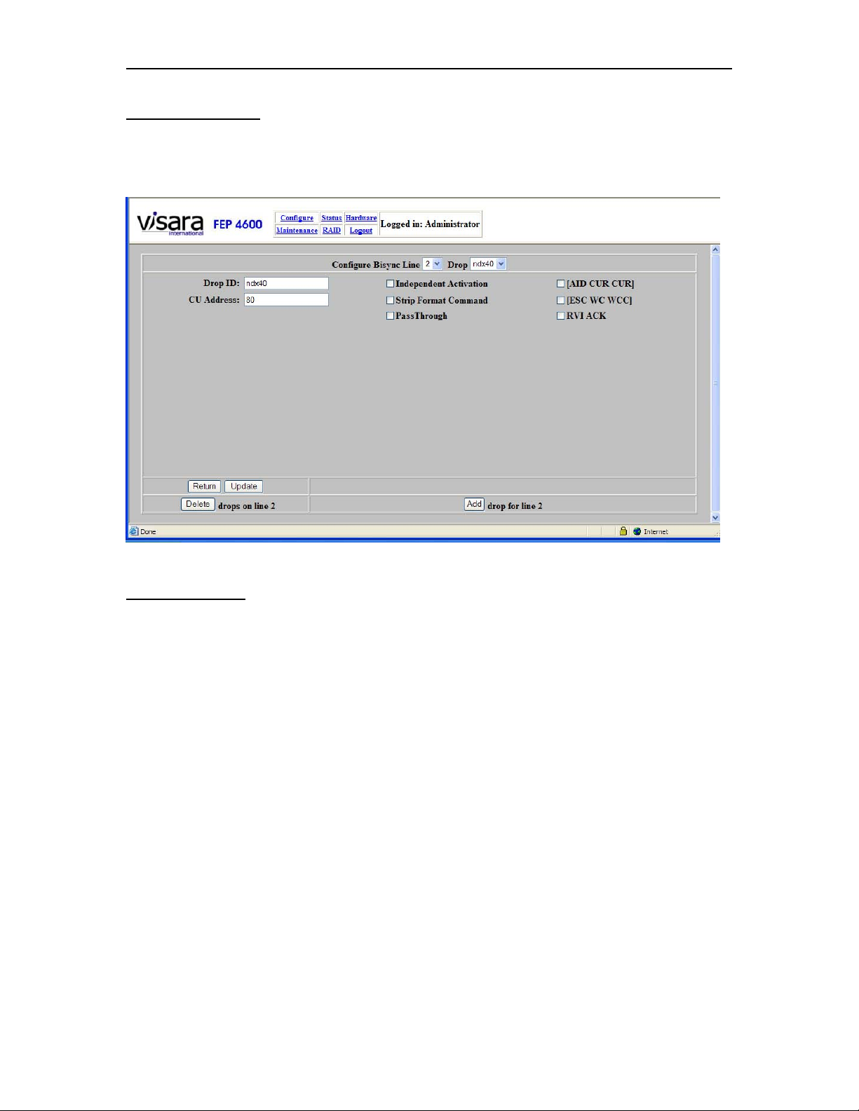
Chapter 8. 3270 Bisync Interface
Bisync Drop Panel
By selecting the ‘Drops’ button the following Bisync Drop Configuration panel will
display.
Field Definitions
Drop ID: This is a text field (alphanumeric plus underscore, dash, and period) that you
can enter a description for the Bisync Drop to make it more recognizable for management
purposes.
CU Address: This represents the Poll address configured on the downstream Bisync
platform. Only codes from the IBM Control Code chart are valid. See the chart below.
Check Box Items:
• Independent Activation
• Strip Format Command
• Pass Through
• [AID CUR CUR]
• [ESC WC WCC]
• RVI ACK
8-6 707119-001
 Loading...