

Page 1

1783 Network Computing Terminal
User’s Manual
P/N 707042-002
Page 2

The information contained in this document is subject to change without notice. Visara, Inc. makes no warranty of any kind with
regard to this material including, but not limited to, the implied warranties of merchantability and fitness for a particular
purpose. Visara, Inc. shall not be liable for errors contained herein or for incidental or consequential damages in connection with the
furnishing, performance, or use of this material.
Safety and Regulatory Information
Safety
* UL1950, CSA950
* CE Mark, IEC950, EN60950, EU Low Voltage
Electro-Magnetic Interference
* This device complies with part 15 of the FCC rules. Operation is subject to the following 2 conditions: (1) This device may not
cause harmful interference, and (2) this device must accept any interference received, including interference that may cause
undesired operation.
Pursuant to part 15.21 of the FCC rules, any change or modification to this equipment not expressly approved by Visara, Inc. may
cause harmful interference, and void your authority to operate this equipment.
* This apparatus complies with the CDoC CLASS “A” limits for radio interference as specified in the Canadian Department of
Communications Radio Interference Regulations. Operation in a residential area may cause unacceptable interference to radio
and TV reception requiring the owner or operator to take whatever steps are necessary to correct the interference.
✦ Cet appariel est conformé aux normes CDoC CLASS “A: D’Interference radio tel que specifier par le Ministère Canadien
des communications dans les règlements D” Interference Radio. Cet équipment ne dépasse pas les limites de Classe B
d’émission de bruits radioélectriques pour les appareils numériques, telles que prescrites par le Règlement sur le brouillage
radioélectrique établi par le Ministère des Communications du Canada. L’exploitation faite en milieu résidentiel peut entraîner
le brouillage des réceptions radio et télé, ce qui obligerait le propriétaire ou l’opérateur à prendre les dispositions nécessaires
pour en éliminer les causes.
✦ CE mark, EN50022, EN50082-1, EU EMC Directive
Patents, Trademarks and Acknowledgments
IBM and SNA are registered trademarks of International Business Machines Corporation.
QNX and Photon microGUI are registered trademarks of QNX Software Systems Ltd.
Voyager is a trademark of QNX Software Systems Ltd.
Other trademarks are the properties of their respective owners.
Portions of the code and documentation described in this guide were derived from code and documentation developed under the
auspices of the Regents of the University of California and have been acquired and modified under the provisions that the following
copyright notice and permission notice appear:
©Copyright Regents of the University of Califormia, 1986, 1987. All rights reserved.
Redistribution and use in source and binary forms are permitted provided that this notice is preserved and that due credit is given the
University of Califormia at Berkeley. The name of the University may not be used to endorse or promote products derived from this
software without specific prior written permission. This software is provided “as is” without express or implied warranty.
NCSA Mosaic was developed by the National Center for Supercomputing Applications at the University of Illinois at Urbana-Champaign.
This version is being distributed under a license agreement with Spyglass, Inc.
This publication contains materials licensed to Visara, Inc., by QNX Software Systems Ltd.
Portions (C) Copyright 1997 by QNX Software Systems Ltd.
P/N 707042-002
© Copyright 2000 Visara, Inc.
ii 707042-002
Page 3

Warranty/Service
Warranty service must be performed by the assigned warranty service provider for the
equipment. If you are unsure of the equipment warranty status or who can perform
warranty service, please e-mail us at [email protected], or call 919-279-6022.
Please include your equipment model and serial number. The serial number is located
at the base of the unit.
1. If your equipment packaging appears to have been damaged in shipment, please do
not open it. Rather, you should report the damage to the carrier upon delivery. If
you determine that your equipment has concealed damage when you open the
package, report the damage to your carrier as soon as possible. In both situations,
you should also call Visara Customer Service to report the problem and have a
replacement shipped to you.
2. If you elected to have Visara perform the installation of your equipment call
1-800-777-8800. Refer to the national program code as “Visara1” and report your
customer number as “8718145”. The customer service representative will then
schedule your installation.
3. If your equipment fails to work properly during its initial installation or within 48
hours, please call Customer Service to report the problem and have a replacement
shipped to you.
Call 1-888-334-4380 X6201
Call 1-888-334-4380 X6201
4. For additional technical support, the Visara IntelliCenter is our technical support hub
and can be reached by calling:
1-919-279-6022
707042-002 iii
Page 4

Page 5

Table of Contents
1. About This Manual ...............................................................................1-1
Who should use this Manual ............................................................ 1-2
How to interpret the styles and symbols used in this Manual ......... 1-2
Keyboard input.............................................................................. 1-2
Keyboard chord instructions ......................................................... 1-2
Mouse conventions .......................................................................1-3
Notes, cautions, warnings .............................................................1-3
2. About the 1783 NCT..............................................................................2-1
Overview ..........................................................................................2-2
Standard features .............................................................................. 2-2
Personal productivity tools...............................................................2-3
3. Connecting the 1783 NCT .................................................................... 3-1
Inspecting the package .....................................................................3-2
Setting up the 1783 NCT .................................................................3-2
Connecting the 1783 NCT ............................................................... 3-4
Connecting to the SNA network ................................................... 3-4
Connecting to an Ethernet LAN ...................................................3-4
Connecting a modem to the Serial Port ........................................3-4
Connecting to the 5250 Network .....................................................3-5
Powering up ..................................................................................... 3-5
Powering down.................................................................................3-6
4. Using Windows ...................................................................................... 4-1
Using the 1783 NCT ........................................................................ 4-2
What should I do first?.....................................................................4-2
How to start the 1783 .......................................................................4-2
A typical workspace .....................................................................4-2
Using the mouse ............................................................................... 4-3
Pointers.............................................................................................4-3
Anatomy of a window ...................................................................... 4-4
Using the Window Menu .................................................................4-5
Using the Taskbar.............................................................................4-5
Keyboard shortcuts...........................................................................4-6
Workspace operations ...................................................................4-6
Window operations .......................................................................4-6
5. Using Print Services ..............................................................................5-1
Printer setup .....................................................................................5-2
Installing a printer ............................................................................5-3
Changing the default printer ............................................................ 5-3
Printing when a printer has not been set up .....................................5-3
707042-002 v
Page 6

1783 Network Computing Terminal User’s Manual
Printer properties.............................................................................. 5-4
Paper tab ....................................................................................... 5-4
Graphics tab ..................................................................................5-5
Margins tab ...................................................................................5-5
Other tab ....................................................................................... 5-6
Info tab .......................................................................................... 5-6
Print preview ....................................................................................5-6
LPR/LPD print feature .....................................................................5-7
Configuring remote printers.............................................................5-7
Remote Printer Definition.............................................................5-8
Using the 1783 as an LPR server .....................................................5-8
6. 1480 CUT Emulator .............................................................................. 6-1
Standard features .............................................................................. 6-2
Display screen features .................................................................6-2
Data entry features ........................................................................6-2
Printing features ............................................................................ 6-3
Other features................................................................................6-3
Accessing your application program ............................................... 6-3
Moving the cursor ............................................................................6-4
Entering and editing data .................................................................6-5
Selecting data fields .........................................................................6-5
Sending data .....................................................................................6-6
System Request variations ............................................................6-6
Program Access (PA) function ......................................................6-6
Function (F or PF) keys ................................................................6-6
Monitoring response time ................................................................6-9
Configuring the 1480 CUT Emulator .............................................. 6-9
Defining and selecting features .................................................... 6-9
1480 Miscellaneous .......................................................................6-11
Restarting the 1480 Emulator .....................................................6-11
Keyboard setup ...........................................................................6-12
Color ........................................................................................... 6-13
Printer setup and printing ............................................................... 6-14
Print type ..................................................................................... 6-14
Coax printer assignment .............................................................6-15
HAP Menu ..................................................................................6-16
LPR Menu ................................................................................... 6-18
Dual Screen feature ........................................................................ 6-19
Configuration requirements ........................................................6-19
Configuring Dual Screen mode......................................................6-19
Starting Dual Screen mode ............................................................ 6-20
Active and Suspended Screens ...................................................6-20
Key assignments .........................................................................6-21
Dual Screen Mode enhancements ..................................................6-21
Zoom ........................................................................................... 6-21
Select left ....................................................................................6-21
Select right ..................................................................................6-21
vi 707042-002
Page 7

Table of Contents
Step Active session ..................................................................... 6-22
Swap session ...............................................................................6-22
Mark............................................................................................ 6-23
Paste ............................................................................................6-23
Mark/Paste ..................................................................................6-23
Walk through...............................................................................6-24
Screen Print mode ....................................................................... 6-24
7. 1490 Twinax Emulator ..........................................................................7-1
Standard Features ............................................................................. 7-2
Communication Setup......................................................................7-3
Terminal Mode..............................................................................7-3
Display Address ............................................................................ 7-3
Printer Address..............................................................................7-4
Keyboard Setup ................................................................................ 7-4
Screen Setup.....................................................................................7-8
Display Emulation ........................................................................7-8
Cursor ...........................................................................................7-9
Full Screen Mode..........................................................................7-9
Color Setup ....................................................................................7-10
Printer Setup...................................................................................7-11
Attached Printer Type .................................................................7-11
Printer Emulation ........................................................................ 7-12
Characters per Inch .....................................................................7-12
Lines per Inch .............................................................................7-12
LPR Menu ................................................................................... 7-13
1490 Miscellaneous .......................................................................7-13
Restarting the 1490 Emulator .....................................................7-14
8. Using Telnet, TN3270, TN5250 and VT220 ......................................... 8-1
Telnet Terminal ................................................................................8-2
What is Telnet? .............................................................................8-2
Logging in to a remote host ..........................................................8-2
Logging out of a remote host ........................................................ 8-3
Recommended reference guides ...................................................8-3
TN3270 ............................................................................................ 8-4
What is TN3270? ..........................................................................8-4
Setting up a remote host as a 3270 terminal ................................. 8-5
Connecting to a TN3270 session ..................................................8-6
Logging out of a remote host ........................................................ 8-6
Configuring TN3270 for an application .......................................8-9
Print setup ...................................................................................8-12
Print type ..................................................................................... 8-12
LPR menu ...................................................................................8-13
Copy/Paste Between TN3270 Sessions ......................................8-14
Copy/Paste From Calculator to TN3270 Session .......................8-15
Recommended reference guide ..................................................8-15
707042-002 vii
Page 8

1783 Network Computing Terminal User’s Manual
TN5250 .......................................................................................... 8-16
What is TN5250? ........................................................................8-16
Setting up a remote host as a 5250 terminal ............................... 8-16
Connecting to a TN5250 session ................................................8-17
Logging out of a remote host ...................................................... 8-20
Configuring TN5250 for an application .....................................8-20
Screen setup ................................................................................8-20
VT220 ............................................................................................8-23
What is VT220? ..........................................................................8-23
Setting up VT220 ........................................................................ 8-23
Connecting to a VT220 session ..................................................8-25
Logging out of a remote host ...................................................... 8-25
Configuring VT220 for an application ....................................... 8-26
Miscellaneous setup .................................................................... 8-30
Printer setup ................................................................................8-31
9. TN3270/TN5250 Keyboard Macros ..................................................... 9-1
Keystroke Record/Playback .............................................................9-2
Storing Keystroke Sequences...........................................................9-2
Playing Keystroke Sequences ..........................................................9-3
Removing Keystroke Sequences ......................................................9-3
Advanced Feature Set: Pauses ......................................................... 9-3
Advanced Feature Set: Delays .........................................................9-4
Advanced Feature Set: Playback Speed ........................................... 9-4
Special Notes....................................................................................9-4
10. Accessing your intranet and the Internet ......................................... 10-1
Configuring Voyager Browser ........................................................10-2
Cache tab ....................................................................................10-3
User Info tab ............................................................................... 10-4
Connection tab ............................................................................10-5
Appearance tab ........................................................................... 10-6
Basic browsing ............................................................................... 10-7
Toolbar icons...............................................................................10-7
Browsing the Internet..................................................................10-7
Stopping data transfer .................................................................10-7
Refreshing the current page ........................................................10-7
Going backward and forward .....................................................10-8
Returning to your home page ..................................................... 10-8
Finding text .................................................................................10-8
Changing the size of the font ......................................................10-8
Viewing history ........................................................................... 10-8
Using hotlists .................................................................................10-8
Hotlists ........................................................................................10-8
Adding sites to Hotlist ................................................................10-8
Viewing hotlists .......................................................................... 10-9
Deleting sites from the hotlist.....................................................10-9
Printing ........................................................................................... 10-9
viii 707042-002
Page 9

Table of Contents
11. Using personal productivity tools .....................................................11-1
NCT Mail .......................................................................................11-2
Starting NCT Mail ......................................................................11-2
Checking for - and reading - your mail ...................................... 11-3
To read a message .......................................................................11-3
Replying to and forwarding mail ................................................ 11-3
Sending new mail........................................................................11-4
Message Pad...................................................................................11-5
Posting a note to yourself ........................................................... 11-5
DayMinder .....................................................................................11-6
What is DayMinder? ................................................................... 11-6
Starting DayMinder ....................................................................11-6
DayMinder at a glance ................................................................ 11-6
Resizing windows .......................................................................11-7
Customizing application preferences..........................................11-7
Types of scheduled activities ......................................................11-8
Adding appointments .................................................................. 11-8
Adding reminders ....................................................................... 11-9
Adding a task to the ToDo list .................................................... 11-9
Editing and deleting scheduled activities .................................11-10
Address Book............................................................................11-10
Calculator .....................................................................................11-12
Snapshot .......................................................................................11-12
Printing a snapshot....................................................................11-13
Dial-up connection ....................................................................... 11-13
Starting the Dialer ..................................................................... 11-13
Setup an ISP .............................................................................. 11-14
Typical ISP setup ...................................................................... 11-14
Advanced ISP setup ..................................................................11-15
TCP/IP settings .........................................................................11-15
Modem settings.........................................................................11-15
Login script ...............................................................................11-15
Script Editor .............................................................................. 11-16
12. Safety, Power, and Environmental Requirements ...........................12-1
Space planning: physical statistics ................................................. 12-2
Meeting environmental requirements ............................................12-2
Power cable requirements ..............................................................12-2
For units operating at 100-120V ................................................. 12-2
For units operating at 200-240V ................................................. 12-3
For international units.................................................................12-3
Power outlet requirements ............................................................. 12-3
Electrical interference and atmospheric considerations ................ 12-3
13. System Administrator’s Guide..........................................................13-1
Accessing the configuration screens ..............................................13-2
Administrator Functions ................................................................13-3
Vital Product Data ....................................................................... 13-3
707042-002 ix
Page 10

1783 Network Computing Terminal User’s Manual
Configuring Options ...................................................................... 13-4
Defining Administrator’s Password ............................................... 13-4
Setting date and time......................................................................13-5
Configuring NCT Network ............................................................13-5
Connection tab ............................................................................13-6
Gateway tab ................................................................................ 13-6
DNS tab.......................................................................................13-7
Configuring NCT Mail...................................................................13-8
Configuring NCT Applications ......................................................13-9
Configuring NCT Miscellaneous .................................................13-10
ICA ............................................................................................... 13-11
Configuring ICA .......................................................................13-11
Application servers ...................................................................13-12
Network tab...............................................................................13-12
Connection Options tab ............................................................ 13-12
Application tab..........................................................................13-13
Starting the ICA session ........................................................... 13-14
NCT Update configuration...........................................................13-15
NCT Update troubleshooting process.......................................13-16
Update list file format ............................................................... 13-16
Language configuration ...............................................................13-17
Ping .............................................................................................. 13-17
Index ....................................................................................................Index-1
x 707042-002
Page 11

Chapter 1
About This Manual
In this Chapter...
Who should use this Manual
How to interpret the styles and symbols used
in this Manual
Page 12

1783 Network Computing Terminal User’s Manual
Who should use this Manual
This manual accompanies the 1783 NCT and is intended to support the end users in the
operation of this device. It will also provide assistance to those personnel who are tasked
with installing this device.
How to interpret the styles and symbols used in this Manual
Throughout this manual, we use certain typographical conventions to distinguish
technical terms:
Keyboard input
The following table summarizes our keyboard conventions:
:ecnerefeR:noitinifeD:elpmaxE
draobyeK
sdrohc
draobyeK
tupni
draobyeK
syek
syekdesserped
draobyek
desserpedyekelgnisAretnE
yltnerrucnocfonoitanibmocA
ehtnodepytsitahttupniresU
Keyboard chord instructions
A keyboard chord is a single-step instruction that is formatted like this:
➤ To move the window, press Ctrl - F7.
retnE-tlA-lrtC
epytuoygnihtemoS
1-2 707042-002
Page 13
Chapter 1: About this manual
Mouse conventions
A 2-button mouse accompanies the 1783 NCT. Please review the installation section for
proper connections.
The left mouse button is used most of the time. Any procedure that requires using the
secondary button will state specifically to “click the right mouse button”.
:ecnerefeR:noitinifeD
tnioP
kcilC
kcilC-elbuoD
garD
.esuomeht
.esuomehtgnivom
neercseht
.neercsehtnotatniopottnawuoyrevetahw
Notes, cautions, warnings
Notes, cautions and warnings are used to highlight important messages:
Note: Notes point out something important or useful.
CAUTION: Commands or procedures that may have unwanted or undesirable side effects.
WARNING: Commands or procedures that could be dangerous to your files, hardware,
or even yourself.
nostserretniopehtfopitehttahtosretniopesuomehtnoitisoP
gnivomtuohtiwnottubesuomehtesaeleryletaidemmidnasserP
tuohtiweciwtnottubesuomehtesaeleryletaidemmidnasserP
ssorcaretniopehtgnivomelihwnottubesuomehtnwoddloH
707042-002 1-3
Page 14

Page 15

Chapter 2
About the 1783 NCT
In this Chapter...
Overview
Standard features
Personal productivity tools
Page 16

1783 Network Computing Terminal User’s Manual
Overview
The 1783 NCT is designed to address the requirements of host centric and network centric
users. The 1783 platform supports a real time operating system and a graphical user
interface (GUI). The presence of a micro-kernel, modularized POSIX compliant operating
system allows the 1783 to provide power and flexibility not available in server based
network terminals. The 1783 supports connectivity over Type A Coax, Ethernet, Twinax,
Token Ring, and Serial Ports to IBM hosts, UNIX hosts and Microsoft hosts in a windowing
environment. This connectivity allows a user simultaneous access to SNA, intranet and
Internet networks. Designed with no moving parts, the 1783 NCT is a zero maintenance
device that allows software installation and updates from a central location.
The 1783 NCT is easy to install, use, manage and support. Maintaining software and data
at a central location eliminates the need to store applications and/or data on a conventional
desktop workstation. Business applications, corporate intranets and the Internet can all
be accessed from one network terminal.
The 1783 NCT is unique among network computers because of its resident operating
system and the caching in flash memory of frequently used applications (such as the
1480 Emulator, Telnet, TN3270 and TN5250 host access, the Voyager
Citrix© ICA Client, and personal productivity tools). This flash memory caching effectively
eliminates the delay encountered with server-based systems when many users log on
simultaneously.
TM
Web browser,
Standard features
Access to your applications is through a ‘windowing’ environment called a graphical user
interface (GUI). This GUI, Photon micro-GUI, makes it easy to interact with the terminal
and enhances flexibility to a variety of tasks.
The following are standard features of the 1783 NCT:
• An Internet browser, called Voyager
and JAVA scripts.
• Telnet Terminal client capability that enables log-in to host systems that are connected
to the Internet.
• A TN3270E client capability that enables accessing 3270 applications on host systems
that are connected to a LAN/WAN using terminal model type IBM 3279 mod 2,
mod 3, mod 4, and mod 5.
• A TN5250 client that enables accessing AS/400 applications.
• Print capability that directs printed material either to a local printer or to a network
printer.
The following are options of the 1783 NCT:
• A 1480 CUT Emulator (mods 2 - 5) that works with any 1174 compatible control unit.
• A 1490 native Twinax (mods 2 - 5) that work with AS400 systems.
• Token Ring
TM
, that supports HTML 3.2, frames, tables, graphics
2-2 707042-002
Page 17

Personal productivity tools
• NCT Mail – A mail handler to use for reading, replying to, forwarding and creating
e-mail (electronic mail).
• Message Pad – A handy way to post a note to yourself.
• Day Minder – An online appointment book.
• Calculator – A convenient on-screen calculator.
• Dialer – A utility that allows the 1783 to be connected to other environments via an
external modem.
• SnapShot – A resident software utility that allows a displayed image to be printed
on your locally attached printer.
Chapter 2: About the 1783 NCT
707042-002 2-3
Page 18

Page 19

Chapter 3
Connecting the 1783 NCT
In this Chapter...
Inspecting the package
Setting up the 1783 NCT
Connecting the 1783 NCT
Powering up
Powering down
Page 20

1783 Network Computing Terminal User’s Manual
Inspecting the package
Before unpacking the 1783 NCT, inspect the carton for physical damage. If the exterior
package is damaged, contact your local sales office or distributor. Also contact the carrier
to request examination of the damage. The carrier is required to complete and sign a
damage report form. If the package is not damaged, remove the package contents which
includes a logic unit, a mouse, an AC power cable, and this user’s guide.
Setting up the 1783 NCT
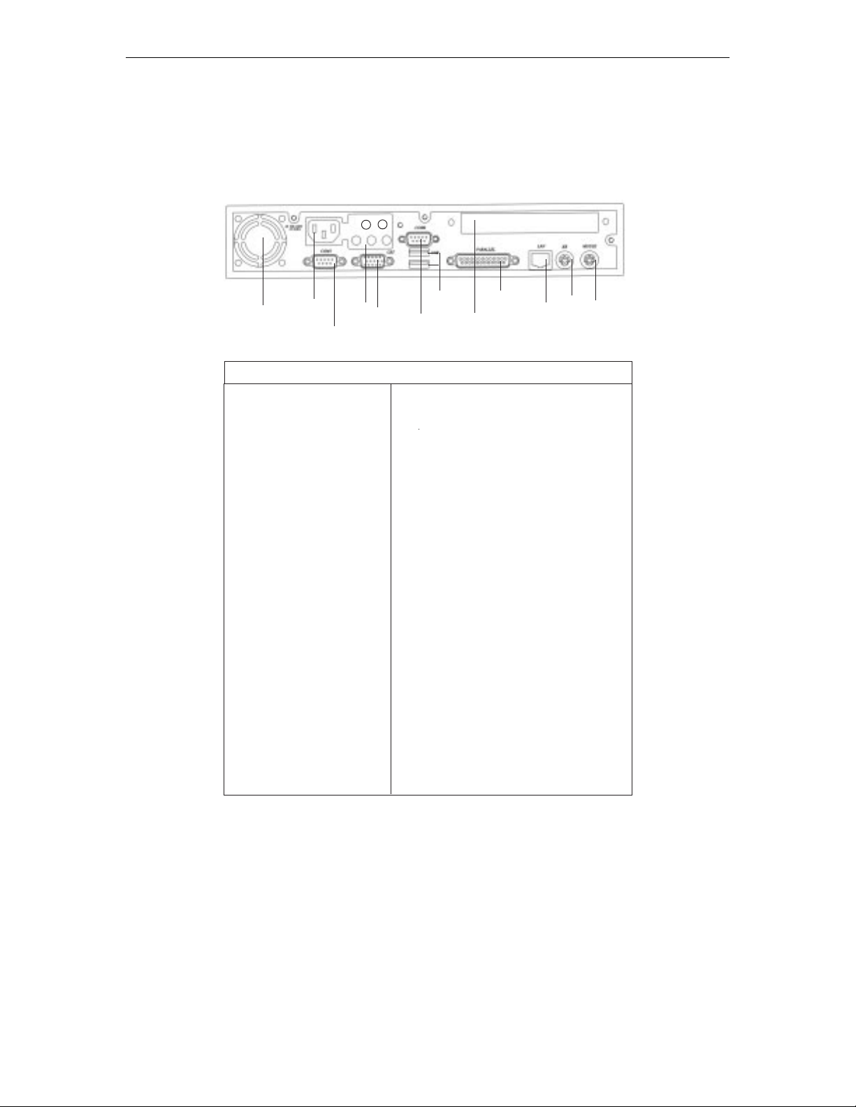
To set up the 1783 NCT, refer to the diagram on the back of the logic unit and follow the
steps below:
CAUTION: The 1783 NCT has been designed to support the weight of 17-inch or smaller
display units. Display units larger than 17 inches MUST be placed beside the logic unit,
rather than on top.
1. Place the display unit on top (or beside) of the logic unit and position both within
connecting distance of an appropriate AC power outlet.
2. Make sure that the Power-On/Off switch is set to O (Off) on both the logic unit and
the display unit.
3. Place the keyboard in front of the logic unit. Pull out the feet underneath the keyboard
to adjust it to a higher setting, if desired. Insert the keyboard plug into the keyboard
connector on the back of the logic unit.
4. Refer to the owner’s manual that comes with your display unit for instructions on
how to attach the display unit’s data cable to the logic unit.
5. Plug the display unit’s AC power cable into an appropriate AC power outlet.
6. For the local screen print function, a printer connector is located on the back of the
logic unit. Attach the printer cable (provided with the printer) to the printer connector
on the back of the logic unit.
7. Insert the mouse’s cable connector into the mouse receptacle on the rear of the logic
unit. Check to ensure that the connector is firmly seated.
8. Plug one end of the power cable into the AC connector on the back of the logic unit.
Plug the other end of the AC power cable into the wall receptacle.
707042-0023-2
Page 21
Chapter 3: Connecting the 1783 NCT
1783 NCT - back of logic unit
a
b
e
c
d
1
2
3
Term
1. Fan
2. AC Input
3. COM 1
4. TV Sound Phone Jack
a: S connector
(Option)
b: Composite connector
(Option)
c: Line Out
d: Line In
e: MIC
5. CRT Connector
6. COM 2
7. USB (2 ports)
8. Expansion Card Area
9. Parallel Port
10. RJ 45 Connector
11. PS/2 K/B
12. PS/2 Mouse
4
5
7
6
9
8
Definition
1. System cooling fan
2. Connect to power cord
3. 16550UART connect to one serial
device
4. Connect to TV & sound port
a. Connect to S-video input of TV
b. Connect to NTSC or PAL video
input of TV
c. Connect to speaker or audio signal
input of other devices
d. Connect to audio signal output of
other devices
e. Connect to microphone
5. Connect CRT monitor
6. 16550UART connected to one serial
device
7. Connect to USB devices
8. The place to plug add-on-card
9. Connect to devices with EPP/ECP port
10. Connect to 10/100 base-T Ethernet
cable
11. Connect PS/2 type keyboard
12. Connect PS/2 type mouse
10
11
12
707042-002 3-3
Page 22
1783 Network Computing Terminal User’s Manual
Connecting the 1783 NCT
Connecting to the SNA network
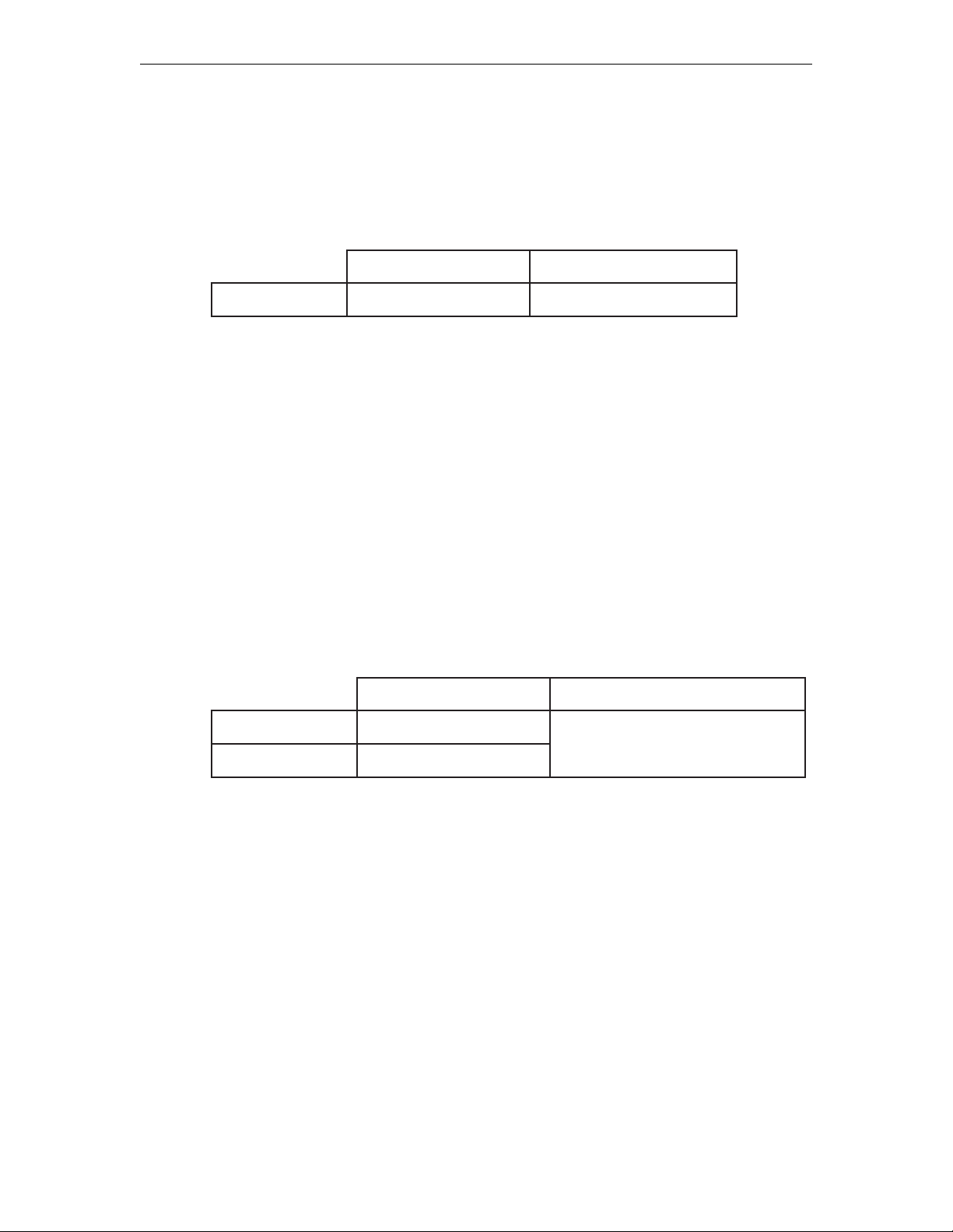
To connect the 1783 NCT to a coax wiring system, prepare either coax cables or twistedpair cables according to the following table:
xaoCriaPdetsiwT
htgnelmumixaM)teef0294(sretem0051)teef009(sretem772
Coax cable and twisted-pair cables can be combined. The following formula shows lengths:
(coax length) + (5 x twisted-pair length) < 1370 meters (4500 feet)
1. Locate the coax or twisted-pair SNA network cable.
2. Align the end of the SNA network cable with the Coax connector on the back of the
logic unit.
3. Connect the cable and secure it in place by turning the retaining ring clockwise until
it is tight.
Connecting to an Ethernet LAN
To connect the 1783 NCT to an Ethernet LAN, prepare the Category 5 or unshielded
twisted-pair cables according to the following table:
1. Locate the Category 5 UTP Local Area Network (LAN) cable.
5ro,4,3yrogetaCdradnatSEEEI/ISNA
htgneLmumixaM)teef480.823(sretem001
htgneLmuminiM)teef182.3(retem0.1
2. Plug the LAN cable into the RJ45 connector on the back of the logic unit.
Connecting a modem to the Serial Port
1. Connect the external modem’s 9-pin connector into the serial port located on the rear
panel of the logic unit.
2. Secure the cable’s fastening screws to ensure proper connection.
retaergro41noitceS0991-I3.208
707042-0023-4
Page 23

Connecting to the 5250 Network
Connect the display station to the host system or to a controller by following these steps
with cable lengths as indicated:
epyTelbaCtnelaviuqero,7029nodleB,8189ahplA
htgneLmumixaMsretem0051
1. Locate the twinax cable extending from the host system or from the closest device on
the host system side of the line. Attach the connector at the end of this cable to either
socket on the two-socket end of the T-connector cable.
2. Push the connector into the socket and turn the retaining ring clockwise until tight.
3. Align the 9-pin Sub-D connector end of the T-connector cable with the twinax
connector on the back of the logic element. Connect the cable to the logic element
and secure it in place by turning the retaining screws until tight.
4. If there are other terminals in the daisy chain, connect the second cable from the next
terminal to the unused socket of the two-socket end of the T-connector cable before
attaching the T-connector cable to the back of the logic element.
Chapter 3: Connecting the 1783 NCT
5. Make sure the twinax line is terminated properly. The last T-connector should have
one input open. If the last device is a Visara device, it must has a T-connector. If the
last device is not a Visara device, ensure that it is terminated correctly according to
the manufacturer’s instructions.
Note: When one connector of the two-socket end of twinax cable is unattached, the cable
is self-terminating. When the single end of the connector cable is unattached, the cable is
in Pass Through mode, and signals continue on to the next connected device. Never attach
the twinax cable directly to the logic element.
Powering up
After the 1783 NCT has been properly installed and connected, it is ready to operate
online. To ensure that the 1783 NCT is prepared for operating, perform the following
procedure. If you encounter operational difficulty or if the unit malfunctions, contact
your system administrator.
1. Set the Power-On/Off switch to On ( | ) to turn on power.
2. If the Power-On indicator does not light, check the power and make sure the unit is
completely plugged in. If the mouse pointer does not appear, or the Taskbar does not
appear, check to see if connecting cables are securely connected to the back of the
logic unit.
3. A beep indicates that the terminal is connected properly. If you hear more than one
beep, check the table on the following page for actions to take.
707042-002 3-5
Page 24

1783 Network Computing Terminal User’s Manual
rebmuN
speebfo
2
2trohs2rorreTSOPelbarevoceR
3trohs3rorreTSOPelbarevocer-noN.rotartsinimdametsysruoytcatnoC
3
3
3
4
4
5
5
noitaruDnoitpircseDnoitcAyrevoceR
gnol1
trohs1
gnol1
trohs2
gnol1
trohs2
gnol2
trohs1
gnol2
trohs2
gnol3
trohs1
gnol2
trohs3
gnol3
trohs2
rorre
rorredraobyeK
nacsMOR,evitcasiyalpsidfI
yromemreppunirorre
,evitcatonsiyalpsidfI
rorreyalpsid
rorrenoitazilaitinixaoC
rorrenoitazilaitinixaoC/PI
rorreyalrevoyromemxaoC
noitazilaitinirevird-xaoC/PI
3871ehtgniniatbororrE
noitarugifnockrowten
.rotartsinimdametsysruoytcatnoc
,stsisrepmelborpfI.noitcennocdraobyekkcehC
,stsisrepmelborpfI.noitcennocdraobyekkcehC
.rotartsinimdametsysruoytcatnoc
.rotartsinimdametsysruoytcatnoC
fI.noitcennocdrocrewopdnatinuyalpsidkcehC
.rotartsinimdametsysruoytcatnoc,stsisrepmelborp
tcatnoc,stsisrepmelborpfI.noitcennocxaockcehC
.rotartsinimdametsysruoy
tcatnoc,stsisrepmelborpfI.noitcennocxaockcehC
.rotartsinimdametsysruoy
,stsisrepmelborpfI.nokcabdnaffotinuehtrewoP
.rotartsinimdametsysruoytcatnoc
tcatnoc,stsisrepmelborpfI.noitcennocxaockcehC
.rotartsinimdametsysruoy
,stsisrepmelborpfI.nokcabdnaffotinuehtrewoP
.3871ehterugifnocerrotartsinimdametsysehtevah
6
6
7
7
gnol2
trohs4
gnol3
trohs3
gnol2
trohs5
gnol3
trohs4
4. Adjust the brightness control, the contrast control, vertical centering, and the horizontal
centering control, if necessary.
Powering down
1. Save all work in process and close any open applications.
2. Move the Power On/Off switch to Off (O).
The next chapter describes how to define characteristics and preferences for the display
unit and printer so that you may begin to use the Network Computing Terminal.
rorrenoitazilaitinitenrehtE
sserddaPInagniniatbororrE
locotorpPtoobehtgnisu
srevirdPCHDgnidaolrorrE.nokcabdnaffotinuehtrewoP
tsohgniniatbororrE
noitamrofninoitarugifnoc
tcennoc
.rotartsinimdametsysruoy
.rotartsinimdametsysruoy
ehtrewopnehtdnanoitcennoctenrehtEehtkcehC
tcatnoc,stsisrepmelborpfI.nokcabdnaffotinu
tcatnoc,stsisrepmelborpfI.revresPtoobehtkcehC
,stsisrepmelborpfI.nokcabdnaffotinuehtrewoP
.3871ehterugifnocerrotartsinimdametsysehtevah
707042-0023-6
Page 25

Chapter 4
Using Windows
In this Chapter...
Using the 1783 NCT
What should I do first?
How to start the 1783
Using the mouse
Pointers
Anatomy of a window
Using the Window Menu
Using the Taskbar
Keyboard shortcuts
Page 26
1783 Network Computing Terminal User’s Manual
Using the 1783 NCT
This section introduces the new operating environment of the 1783 Network Computing
Terminal (NCT). It explains how to do most tasks and provides tips for getting the most
out of the NCT.
If you have used windowing systems before, the “look and feel” will seem quite natural.
If not, the intuitive interface is easy to learn and use.
What should I do first?
First, read through the next section - all the basics about using the mouse and working
with windows are explained, and some handy keyboard shortcuts are included. After
reading this section, familiarize yourself with the display’s workspace. Try starting an
application from the start menu - the Day Minder is a good place to start.
How to start the 1783
The system has been set up to start automatically at power-up. Your user ID and/or password
may be required in the 1783 NCT login dialog box.
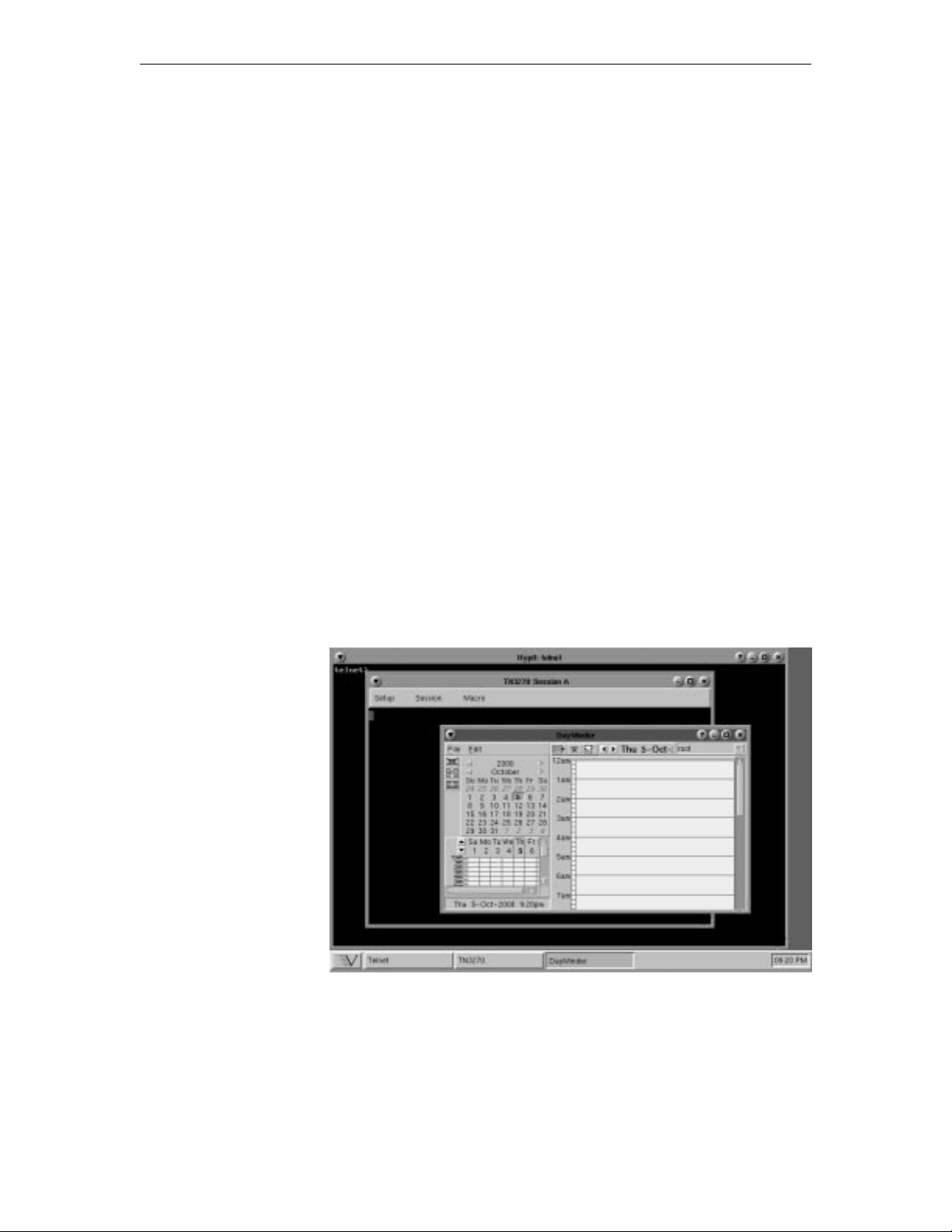
A typical workspace
After the 1783 has started, it will display a workspace, an area in which you can run
applications and display windows. Here is a typical workspace, with some sample
applications:
At the very
bottom of the
screen, the
Taskbar shows
at a glance all
the applications
available on
your desktop.
The taskbar
allows quick
switching from
one application
to another. To
learn how to use
the Taskbar, see
Using the
Taskbar in this
section.
707042-0024-2
Page 27
Using the mouse
Two common mouse operations are:
• Clicking – Pressing and releasing a mouse button.
• Dragging – Holding down a mouse button, moving the mouse, and then releasing the
button.
Note: When the word “click” or “drag” is used in this documentation, and no mouse
button is specified, use the LEFT mouse button. When the right button should be used
you will be explicitly instructed to do so.
Use the right mouse button to bring up a context-sensitive menu in most applications.
Pointers
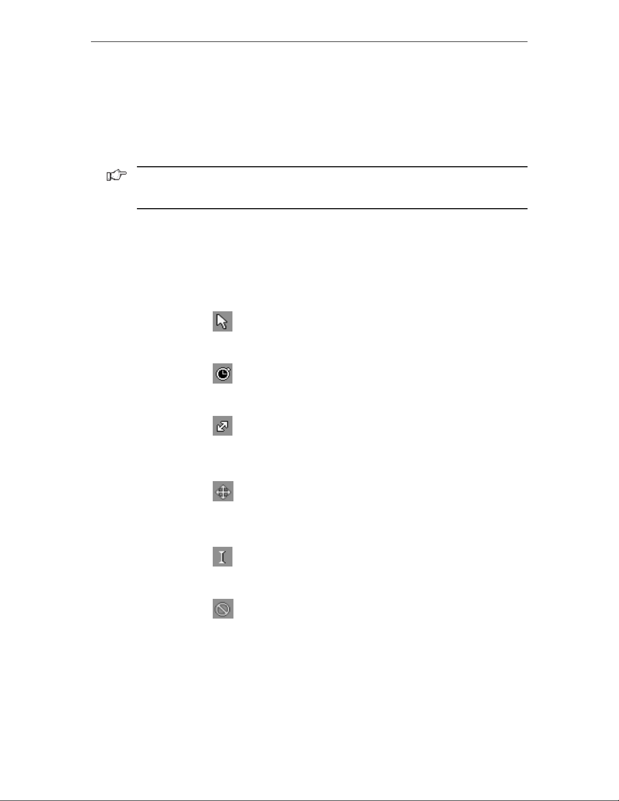
As the mouse is moved, the pointer sometimes changes to provide feedback. Here are the
pointers most often seen:
Chapter 4: Using Windows
Basic pointer - point to objects to be selected
or to indicate where the cursor should be
positioned.
Busy pointer - Indicates that an operation is
in process and must finish before data entry
can be resumed.
Resize pointer - appears when the pointer
passes over a window frame; the two arrows
indicate the direction the window can be
resized.
Move pointer - appears when the pointer
passes over a window title bar; simply hold
down the mouse button and drag the window
to a new location.
I-beam pointer - appears in text-entry fields
to indicate that the application is ready to
accept keyboard input.
No-input pointer - Indicates the window is
not accepting input.
707042-002 4-3
Page 28

1783 Network Computing Terminal User’s Manual
Anatomy of a window
Here is a typical 1783 NCT application window:
Maximize/Restore
Close
Resize
Corner
Window
menu
button
Frame
Title bar
Minimize
Application help
Most windows include these elements:
• Window menu button – Provides modification tools for the window (Restore, Move,
Size, Minimize, Maximize, To Back and Close).
• Minimize button – Reduce the window to an application button in the Taskbar. To
bring the window back up, click the application button on the Taskbar.
• Maximize/Restore button – Expand the window to fill the current workspace, or
restore it to its previous size after maximizing.
• Title bar – Displays the name of the application. The title bar is also where the mouse
pointer should be positioned in order to move the window.
• Frame – Changes color to indicate the focus window (that is, the one that’s ready for
input) on the workspace. The frame is also the area to grab to resize the window.
• Resize corner – Allows shrinking or stretching of the window.
• Close button – Some applications may use this convenient method of closing the
window.
707042-0024-4
Page 29
Using the Window Menu
To open an application’s Window menu, click on the Window menu button in the window’s
upper left corner.
The Window menu allows you to:
• Restore the window’s size (after maximizing or minimizing it).
• Move the window – the window will track the mouse pointer until the mouse button
is clicked.
• Size the window – as the pointer is moved outside the frame, an outline will track it
until the mouse button is clicked.
• Minimize the window – reduces the window to an application button in the Taskbar.
To bring the window back up, just click on the button in the Taskbar.
• Maximize the window – expands the window to fill the current workspace.
• To Back – pushes the window behind any other windows that are open on the
workspace.
• Close – closes the application. An application can also be closed by double-clicking
on the menu button.
Chapter 4: Using Windows
CAUTION: Selecting the Close item may immediately terminate the application running
in that window without prompting you to confirm. Always remember to save your work
before you click on Close!
Note: Some tabs or tool bar icons may be subdued or “grayed out”; these tasks are not
accessible at this time.
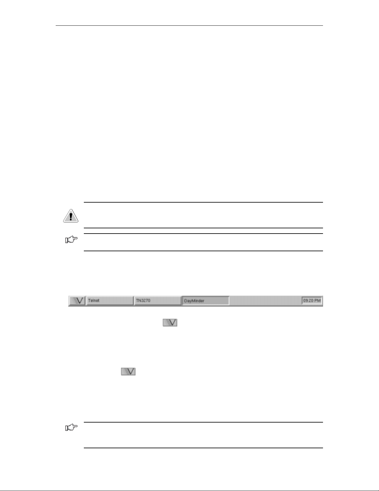
Using the Taskbar
The Taskbar provides a quick and easy way to switch from one application to another and
to restore applications to their normal size on the workspace.
The Taskbar includes the following:
• Application list button -
your use by your system administrator.
• A label button for each application that is running. The label will appear whether the
application is visible on the screen or in the minimized mode.
To start-up an available application:
1. Click the
2. Select the application you wish to work with.
displays a menu of applications made available for
button. The menu of applications will appear.
To switch to any running application, click on the application’s button on the Taskbar.
The application’s window will be restored if minimized, brought to the front, and will
become the focus window.
Note: The system administrator may have configured your 1783 NCT to automatically
start an application in full screen mode when the 1783 NCT is powered on. The application’s
section in this document will describe how to access the taskbar from a full screen.
707042-002 4-5
Page 30
1783 Network Computing Terminal User’s Manual
Keyboard shortcuts
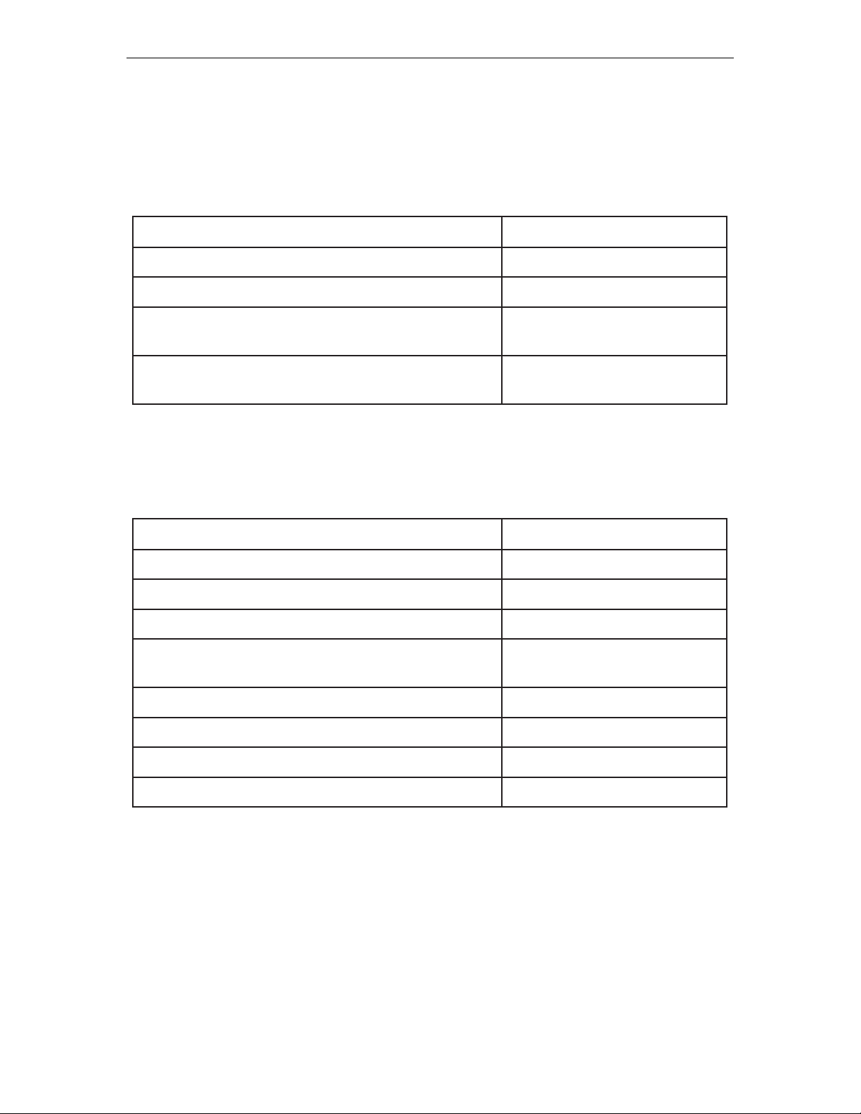
The following tables summarize the keyboard shortcuts that may be used.
Workspace operations
:ottnawuoyfI:sserP
kcatswodniwehtfotnorfehtotwodniwkcabehtevoMcsE-tlA-lrtC
kcatswodniwehtfokcabehtotwodniwtnorfehtevoMcsE-tfihS-tlA-lrtC
kcab
Window operations
All of these commands affect the focus window:
:ottnawuoyfI:sserP
tnorfehtotwodniwehtevoM2F-tlA-lrtC
kcabehtotwodniwehtevoM3F-tlA-lrtC
wodniwehtesolC4F-tlA-lrtC
dezimixam
wodniwehtevoM7F-tlA-lrtC
;tsrifemanehtgniwohs,snoitacilppanepohguorhtelcyC
tlAesaeler,tnorfehtotnoitacilppadeyalpsidagnirbot
ottnorfgnivomtub,snoitacilppanepohguorhtelcyC
neebsahtifiezissuoiverpstiotwodniwehterotseR
baT-tlA-lrtC
baT-tfihS-tlA-lrtC
5F-tlA-lrtC
wodniwehtezimixaM01F-tlA-lrtC
unemwodniwehtyalpsiDecapS-tlA-lrtC
unemwodniwehtesolCcsE
707042-0024-6
Page 31

Chapter 5
Using Print Services
In this Chapter...
Printer setup
Installing a printer
Changing the default printer
Printing when a printer has not been set up
Printer properties
Print preview
LPR/LPD print feature
Configuring remote printers
Using the 1783 as an LPR server
Page 32
1783 Network Computing Terminal User’s Manual
This chapter shows you how to install and select printers, and how to preview documents
before printing.
Printer setup
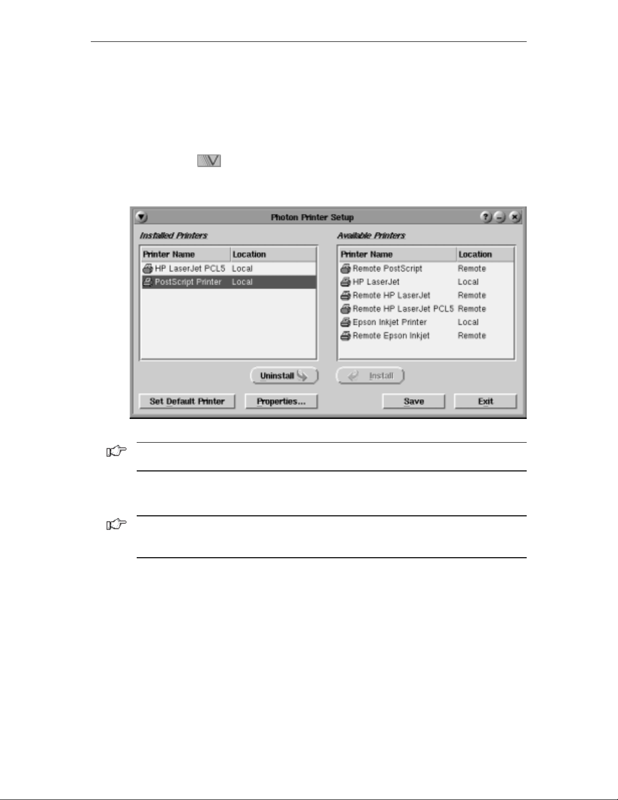
The first step in being able to print files is to select a printer from the Printer Setup dialog.
1. Click the button (located at the lower left-hand corner of the screen).
2. Click Printers. The Photon Printer Setup panel will appear:
Note: Contact your system administrator if there are no printers listed in the Available
Printers panel.
The options of the printer setup dialog are:
• Installed Printers – Displays the list and location of printers that are installed.
Note: Local means there is a parallel printer attached to this unit. For remote location
printers to print, they must be configured using the Remote Printers application. (See
Configuring Remote Printers, page 5-7.)
• Available Printers – Displays the lists and location of printers that may be installed.
Output that goes to spool devices is indicated with a printer icon.
• Install – Installs the printer that is selected in the list of Available Printers.
• Uninstall – Uninstalls the printer that is selected in the list of Installed Printers.
• Set Default Printer – Sets the default printer to the one selected in the Installed
Printers panel.
• Properties – Specify printer options such as paper size, margins, and print quality
for the printer selected in the Installed Printers panel.
• Save – Saves the current configuration.
• Exit – Closes the printer setup window.
707042-0025-2
Page 33
Installing a printer
As many printers as necessary may be installed using the following steps:
1. Click on a printer name from the list of Available Printers in the right panel. The
printer name and location will become highlighted, and the Install button will be
made available for use.
2. Click Install. The selected printer moves to the Installed Printers panel on the left.
Changing the default printer
To change the default printer:
1. Click the printer name that should be selected as the default from the list of Installed
Printers. If it is the only printer selected, the Set Default Printer button will be
made available for use.
2. Click Set Default Printer. The printer which was selected will move to the top of
the list. The Set Default Printer Button changes to Is Default Printer.
When printing from an application, the printer chosen as default is displayed in the Printer
field. Before printing, you can accept the default printer, or choose from any of the printers
in the dropdown printer list.
Chapter 5: Using print services
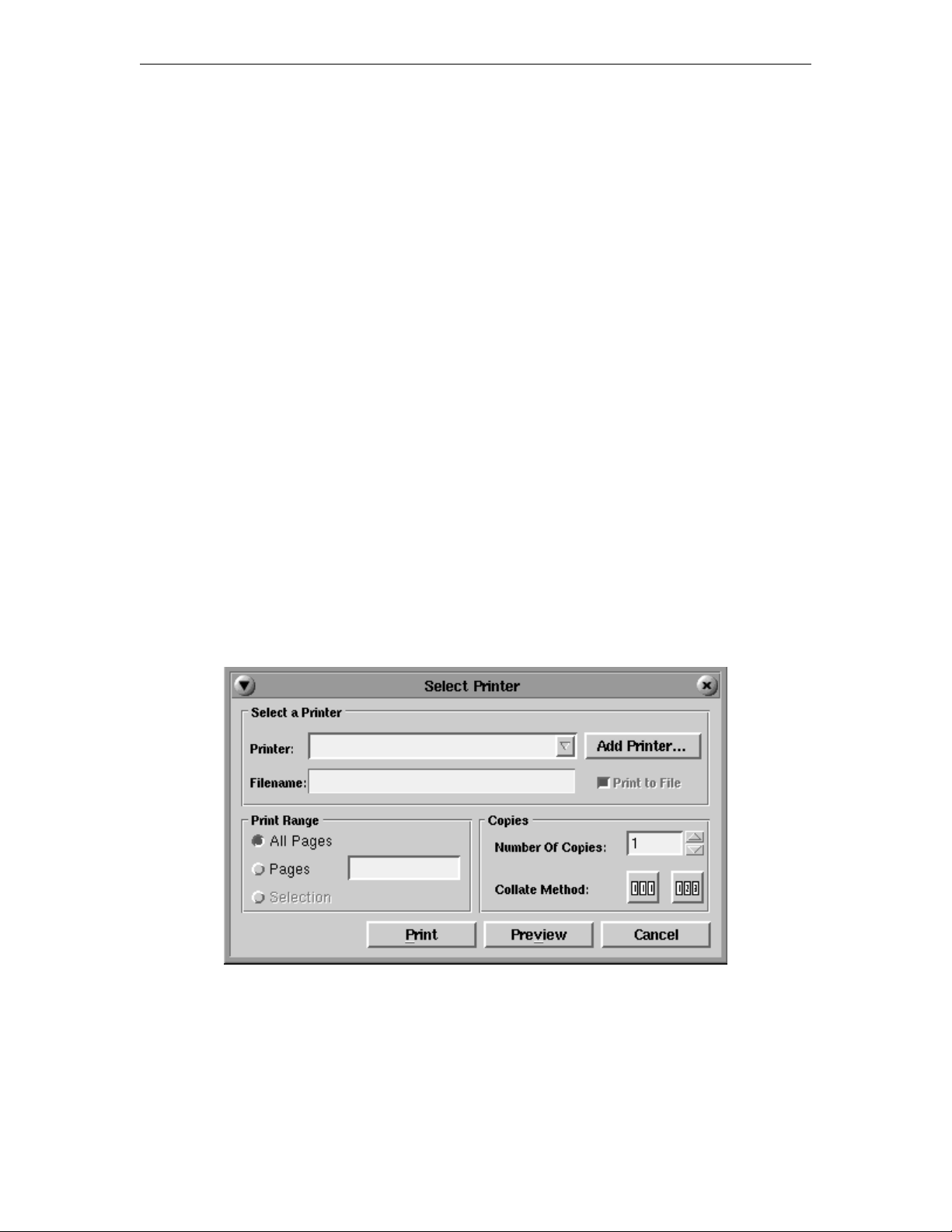
Printing when a printer has not been set up
If a printer was not installed prior to selecting the Print command from an application’s
menu, you will be prompted to install a printer. The Select Printer panel will appear:
Click the Add Printer... button – the Photon Printer Setup panel will open. Install the
printer(s) by following the steps outlined in Installing a Printer.
707042-002 5-3
Page 34
1783 Network Computing Terminal User’s Manual
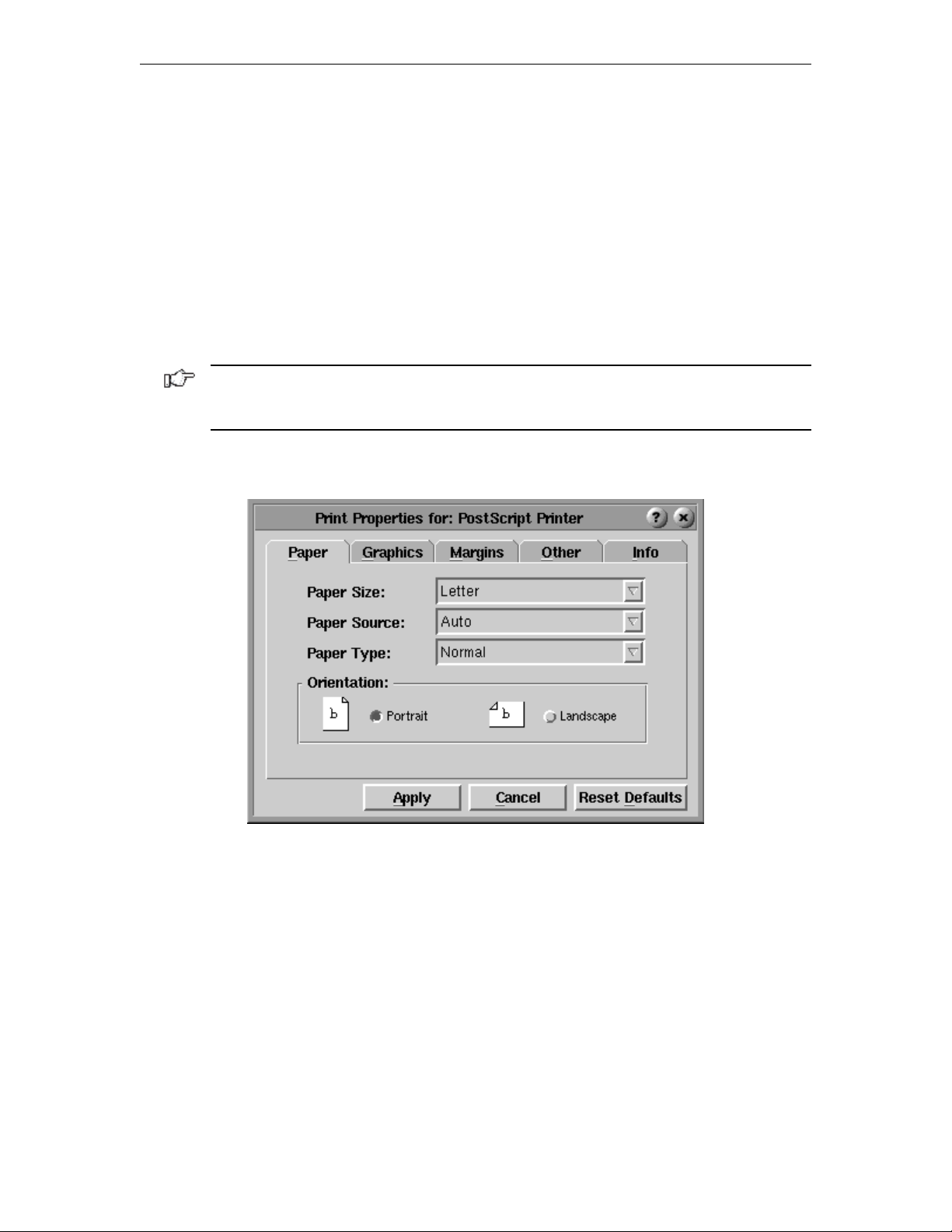
Printer properties
Printer properties can be assigned for either text printing or graphical images. The properties
for the selected printer may be viewed by clicking the Properties button in the Printer
Setup panel (shown on page 5-2).
There are five tabs that display property information:
• Paper tab
• Graphics tab
• Margins tab
• Other tab
• Info tab
Note: The values displayed on your screen for the tab options may differ from the
illustrations in this guide. Refer to your printer’s documentation for the values that define
your printer’s capabilities, or contact your system administrator.
Paper tab
• Paper Size – Select the paper size from the dropdown box, for example, Letter
or Legal.
• Paper Source – Select the paper source from the dropdown box, for example, Auto,
Upper, Lower, Manual or Envelope.
• Paper Type – Select the paper type from the dropdown box, for example, Normal,
High Quality, Draft, Transparency or Envelope.
• Orientation – Select either Portrait or Landscape. The “lit” toggle indicates the
chosen setting.
707042-0025-4
Page 35
Chapter 5: Using print services
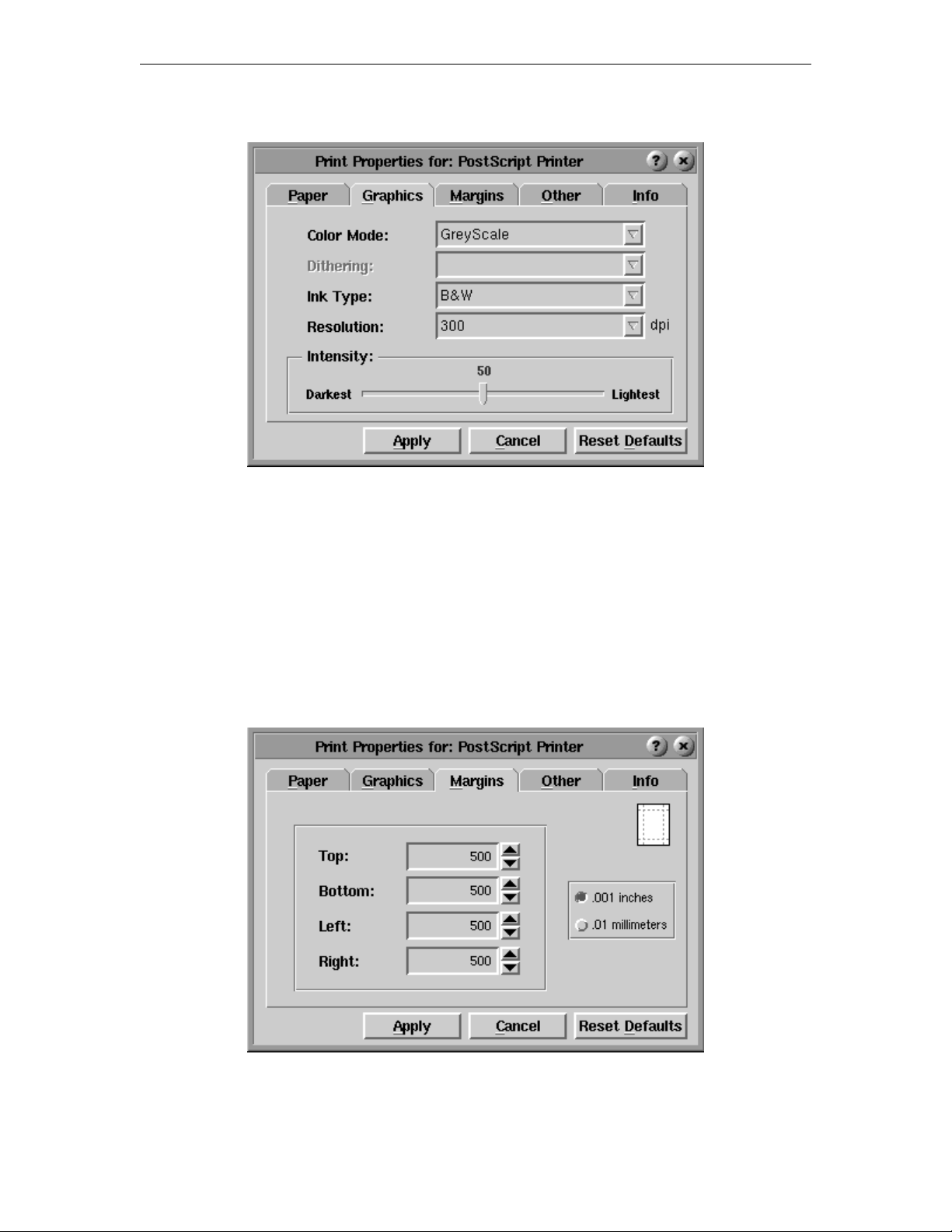
Graphics tab
• Color Mode – Specify the color mode to use, for example, B & W, Greyscale
or Color.
• Dithering – Specify the type of dithering to use, for example, None, Coarse, Fine,
Line Art, Error Diffusion or Half Tone.
• Ink Type – Specify the ink type for the print, for example, Normal, B & W or Color.
• Resolution – Specify the dpi (dots per inch), for example, 75, 150, 300 or 600.
• Intensity – Select the color intensity, ranging from Darkest to Lightest.
Margins tab
Use the Margins tab to change the printer margins:
Margin settings may be set in inches or millimeters. Use the up and down scroll arrows to
increase or decrease the setting. The default is .001 inches.
707042-002 5-5
Page 36
1783 Network Computing Terminal User’s Manual
Other tab
Use this tab dialog to specify single or double-sided printing and the collating mode.
• Duplex – Specifies 1- or 2-sided printing.
• Collating Mode – Select [1,1,1] or [1,2,3] or neither.
Info tab
The Info tab shows the selected printer’s name, location, spool device, and spool
filter information.
When the printer properties configuration is complete, click Apply to save the new settings,
or click Reset Defaults to return to the defaults set by the manufacturer.
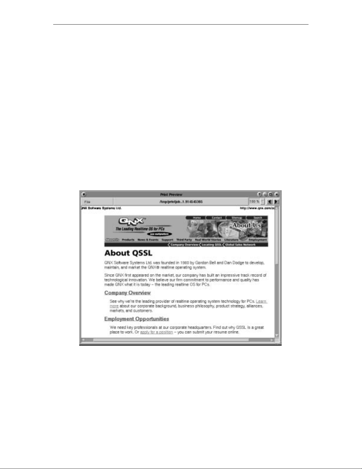
Print preview
Click Preview from the Select Printer panel to preview on-screen how a document will
look when printed.
In print preview you can:
• Scroll forwards and backwards through your document, if it is larger than one page,
by using the Next Page and Previous Page arrows.
• Zoom closer into or further away from the image by selecting a percentage from the
Magnification dropdown box.
• Print the document by opening the File menu (in the upper left-hand corner of the
screen) and clicking Print.
707042-0025-6
Page 37
LPR/LPD print feature
LPR (Line Print Remote)/LPD (Line Print Daemon) is a print server protocol widely
used on the internet for communicating between clients and servers. An LPR-enabled
device (the 1783, for instance) requests a LPD-enabled device (usually a printer or
print server) to print a specific print job. The 1783 can act as an LPR-enabled device
and/or an LPD-enabled device. Following are descriptions of how to configure the 1783
for LPR/LPD.
Remote Printing must be configured to enable LPR printing for the following 1783
applications:
• VT220 • 1480 Emulation
• TN3270E • 1490 Emulation
• TN5250 • Voyager Web Browser
The 1783 supports a total of nine remote printers. Three of these printers are static-defined
and cannot be deleted. The remaining six are user-defined. The three static-defined printers
are:
• lan_hp
• lan_ps
• lan_epson
Chapter 5: Using print services
Configuring remote printers
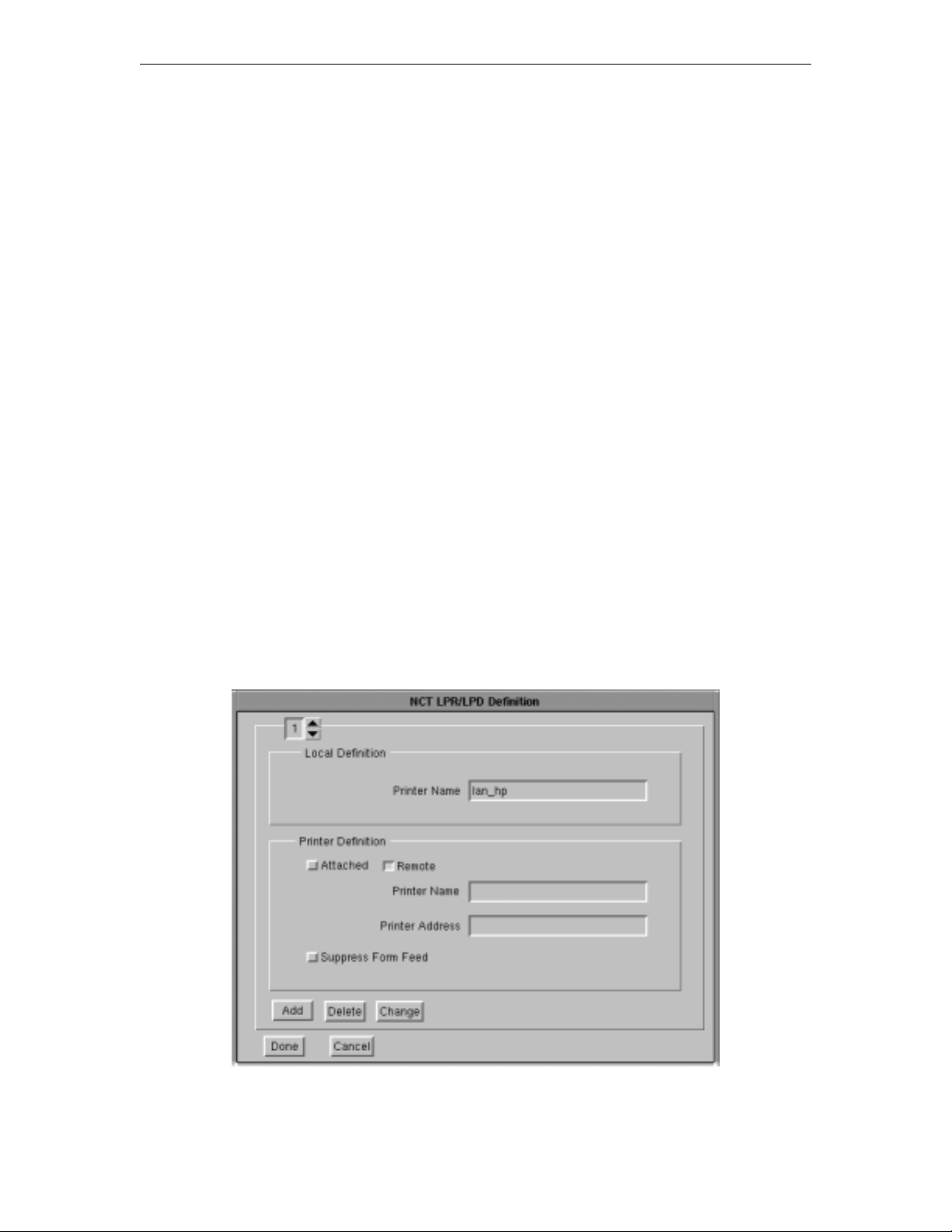
From the Visara application menu, select Remote Printers. The Remote Printer
configuration panel is shown below:
707042-002 5-7
Page 38

1783 Network Computing Terminal User’s Manual
• Remote Printer Selection – Use the up or down arrows to select a printer (1-9)
• Local Definition Printer Name – User-defined field. This name should be a
descriptive name for the remote printer. Note that the first three printers are staticdefined and the Local Definition printer name may not be changed. The remaining six
are user-defined.
Remote Printer Definition
• Attached – the printer is attached to the parallel port on the 1783.
• Remote – the printer is remotely attached on the LAN.
• Printer Name – Queue name that print jobs are sent to from an LPR-enabled device
(if required).
• IP Address – The IP address of the remote printer. If the printer is locally attached,
/dev/par1 is displayed in this field indicating that the printer is attached to the parallel
port. Do not change this entry if the printer is locally defined. Otherwise, enter the
unique IP address of the remote printer.
• Add – Add a new remote printer definition. To add a new remote printer, simply select
an existing printer, make the desired changes, and click Add.
• Delete – Delete an existing remote printer definition.
• Change – Change an existing remote printer definition.
• Done – Save changes and exit.
• Cancel – Discard changes and exit.
Using the 1783 as an LPR server
The 1783 can be configured to act as an LPR server for other 1783’s on the network. To
configure the 1783 as an LPR server:
From the 1783 with the printer attached locally:
Add a new printer definition to Remote Printers. Do this by selecting an existing definition
and making the following changes:
1. Select a Local Definition name, such as lpr_server.
2. Select the Attached button.
3. Select Add. A new printer definition will be created.
From other 1783’s on the network:
Add a new printer definition to Remote Printers. Do this by selecting an existing definition
and making the following changes:
1. Select a Local Definition Printer Name, such as 1783_rem_prtr.
2. In the Printer Definition Printer Name field, enter the local definition name that was
defined above, such as lpr_server.
3. In the Printer Definition IP Address field, enter the IP address of the 1783 with the
locally attached printer.
Note: The 1783 must be restarted when changes are made to Remote Printer configuration
for the changes to become effective.
707042-0025-8
Page 39

Chapter 6
1480 CUT Emulator
In this Chapter...
Standard features
Accessing your application program
Moving the cursor
Entering and editing data
Selecting data fields
Sending data
Monitoring response time
Configuring the 1480 CUT Emulator
1480 miscellaneous
Printer setup and printing
Dual Screen feature
Configuring Dual Screen mode
Starting Dual Screen mode
Dual Screen mode enhancements
Page 40
1783 Network Computing Terminal User’s Manual
The 1480 CUT Emulator is a 1480 Enhanced Function Display Emulator that offers a
wide range of functions and applications for the traditional IBM 3270 terminal user.
The 1480 CUT Emulator can be used with a color monitor or a VGA monochrome monitor.
For remote printing, a coax printer can be attached via the Visara controller, or hard copy
of all data on the screen can be printed on an optional local screen printer or on a remote
LAN printer.
Standard features
The 1480 CUT Emulator provides the following standard features:
Display screen features
• Window Menus – The window menus offer simplicity and ease of use for all setup
functions.
• Switchable Screen Formats – The 1480 CUT Emulator supports four (4) screen
sizes that can be selected from setup menus. The controller to which the 1480 CUT
Emulator attaches must support the screen size used. Check with your system
administrator.
Data entry features
• Mono/DualCase Mode – Allows characters to be displayed as all uppercase
characters or as upper- and lowercase characters.
• Mark Unprotected Field Indicator – The 1480 CUT Emulator can be requested
to mark unprotected fields with a special character.
• Row/Column – Displays the current cursor location on the operator status row.
• Numeric Lock – Allows a field to be defined to accept only numeric characters, plus
the Period, Minus, and Dup keys. The comma may be substituted for the period on
some international keyboard - controller functions.
6-2 707042-002
Page 41

Chapter 6: 1480 CUT emulator
• Audible Alarm – Sounds when a character is entered in the next-to-last character
position of the screen (if the last character position is unprotected) or when the host
system signals the terminal.
• Entry Assist Function – Facilitates the creation and editing of text such as memos,
letters, and documents. The attached controller must support this function.
Printing features
• Local Screen Print – Allows a hard copy of displayed text to be made using the
screen print function. Print quality, line density, and print pitch can be specified.
• Coax Printing – Allows printing to be directed to various printers on your network
or controller.
Other features
• Response Time Monitor – Supports host-controlled transaction response time
monitoring. This feature helps your organization’s systems staff to analyze and improve
the rate at which your terminal responds to your actions. The controller must be properly
configured to support this feature.
• Modifiable Keyboard – Using the Keyboard Definition mode, the keyboard layout
can be modified by interchanging and adding keycaps. The controller must be properly
configured to support this feature.
• Mouse-Pen – Using the right mouse button, light-pen detectable fields can be activated
in the 1480 emulation applications.
• Light-Pen – Light-pen detectable fields can be activated in the 1480 emulation
applications.
Accessing your application program
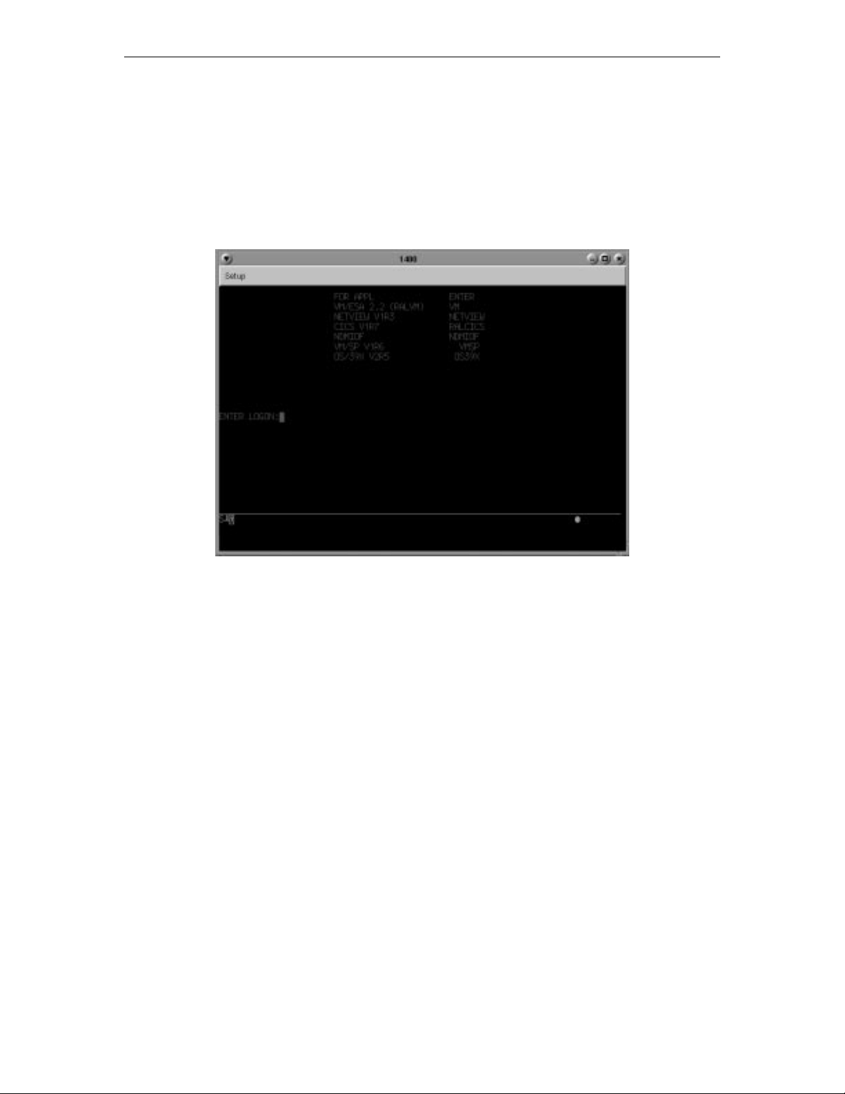
To start the 1480 CUT Emulator:
1. Click the button in the lower left-hand corner of the screen. The application
menu will appear.
2. Click 1480 Emulation from the application menu.
3. Call up an application by one of the following methods:
• Using the Attention, PA, F or PF, Clear, or Enter key,
• Select from your system’s menu of applications.
Contact your supervisor or system administrator for specific information on how to access
your application(s).
The application program can guide your data entry process by:
• limiting numeric fields to digits, period, DUP and minus
• intensifying fields where you can enter data
• covering confidential information so it does not appear on your screen.
Note: To enter nonnumeric, uppercase characters in numeric fields, press Shift.
707042-002 6-3
Page 42
1783 Network Computing Terminal User’s Manual
Moving the cursor
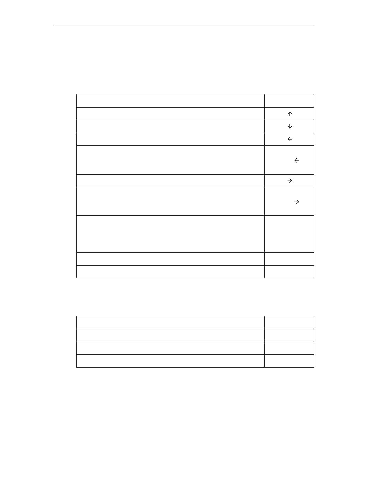
Position and move the cursor on the screen by using the keyboard. Efficiency on data
entry tasks can be significantly increased by using the following keys for positioning the
cursor:
:rosrucehtevomoTyeksserP
neercsehtnopU
neercsehtnonwoD
tfelyllatnoziroH
(emitatasnoitisopowttfeL :etoN dnoyebsevomrosrucehtnehW
retcarahctsalehttasraeppaerro"sparw"ti,neercsehtfoegdeeht
).enilsuoiverpehtfonoitisop
noitisopenothgiryllatnoziroH
(emittatasnoitisopowtthgiR :etoN sevomrosrucehtnehW
tsrifehttasraeppaerro"sparw"ti,neercsehtfoegdeehtdnoyeb
.eniltxenehtfonoitisopretcarahc
)
(eniltxenehtnonoitisopyrtnetsrifehtoT :etoN sirosrucehtnehW
gnisserp,neercsehtfoenilmottobehtnonoitisopyrtnetsalehtta
ehttanoitisopyrtnetsrifehtotrosrucehtsevomyekeniLweNeht
.neercsehtfopot
)
drawkcaB ecapskcaB
neercsehtnonoitisopretcarahcelbaliavatsrifehtoTemoH
)s(
:
-tlA
-tlA
eniLweN
If the application uses a formatted display screen, the following three additional keys can
be used to position the cursor:
:rosrucehtevomoTyeksserP
)s(
:
dleifyrtnetxenehtfonoitisopyrtnetsrifehtotdrawroFbaT
dleifyrtnegnidecerprotnerrucehtninoitisopyrtnetsrifehtotkcaB bat-kcaB
dleifyrtnetneuqesbusaninoitisopyrtnetsrifehtoTpikS
For applications using unformatted display screens, pressing the Tab, Back-tab, or Skip
key returns the cursor to the first available character position on the screen.
6-4 707042-002
Page 43

Entering and editing data
All the keys described in Moving the Cursor can be used to enter and edit data input. In
addition, the following keys can be used to add or delete information:
Chapter 6: 1480 CUT emulator
:noitcnufsihtmrofrepoTyeksserP
tnerrucs'rosrucehttasretcarahcgniddarofedomtresnIretnE
noitisop
edomtresnItixEteseR
noitisoptnerrucs'rosrucehttaretcarahcaevomeReteleD
noitisoprosructnerrucehttagninnigebdrowaeteleD
( :etoN hcihwottinulortnocehtfiylnolanoitcnufsidroWeteleD
).erutaeftsissAyrtnEehtstroppusdehcattasinoitatsyalpsideht
otnoitisoptnerrucs'rosrucehtmorfsnoitisopdleifyrtnellaesarE
dleiffodneeht
tsrifehtotrosrucehtevomdnasnoitisopdleifyrtnellaesarE
noitisopretcarahcelbaliava
noitisopyrtnetsrifehtotrosrucehtevomdnaatadderetnetaepeR
dleifyrtnetneuqesbusehtfo
dleiftupninafodneehtskramtahtretcarahcaretnE kraMdleiF-tfihS
Note: Shift to uppercase characters by using Numeric mode, as well as pressing Shift.
Press either Shift or Shift Lock to reverse Shift Lock.
)s(
:
tresnI
FOErE
pnIrE
puD-tfihS
droWeteleD
Selecting data fields
The application program may be designed to present to you certain fields that can be
selected for further processing by the application program. These fields are marked
with a “?”.
To select a field, perform one of the following actions:
• Press the CrSel key
• Move the cursor to cover any character in the field or to cover the “?” and click the
right mouse button.
“ > ” replaces the “?” associated with the field you select. If you accidentally select the
wrong field, press the CrSel key or right mouse button to deselect it.
707042-002 6-5
Page 44

1783 Network Computing Terminal User’s Manual
To send the field(s) to the application program for processing, do one of the following,
depending on how the application program was designed:
• Press the Enter key.
• Press the CrSel key after positioning the cursor on an attention field. (Attention
fields are marked with &’s and spaces.)
• Position the mouse cursor to point to the desired attention field and click the
right mouse button.
Sending data
To send the displayed data to the host application before continuing to enter data:
1. Check to be sure that all fields required by the application have been filled.
Note: When a data character is entered in the next-to-last character position on the screen,
the audible alarm sounds to remind you that the cursor is near the end of the screen. If
data entry continues, the cursor “wraps”’ and reappears in the first available character
position of the screen. Subsequently entered characters replace displayed characters,
resulting in loss of previous entries.
2. Press the Enter key to send the displayed data to the host application.
3. Press the Clear key. This has the following effect:
• Erases all displayed data on the screen
• Returns the cursor to the first available character position
• Signals the host application that a “clear” operation has occurred.
System Request variations
Depending on the online rules condition symbol that is displayed on the operator status
row, you will be able to send system request messages. Press Alt - Sys Rq, for these
results:
Operator Status
Row Display: Result:
A Sends a message that your unit may be malfunctioning or
that a test request message is on the screen.
B Clears the display and switches the display station between
the control (or master) program and application programs.
Contact your supervisor for additional information about this key combination.
Program Access (PA) function
The application program in use determines specific functions of the Program Access
(PA) key. Contact your supervisor for further information.
Function (F or PF) keys
The application program in use determines specific functions of the Function (F or PF)
keys. Contact your supervisor for further information.
6-6 707042-002
Page 45
Chapter 6: 1480 CUT emulator
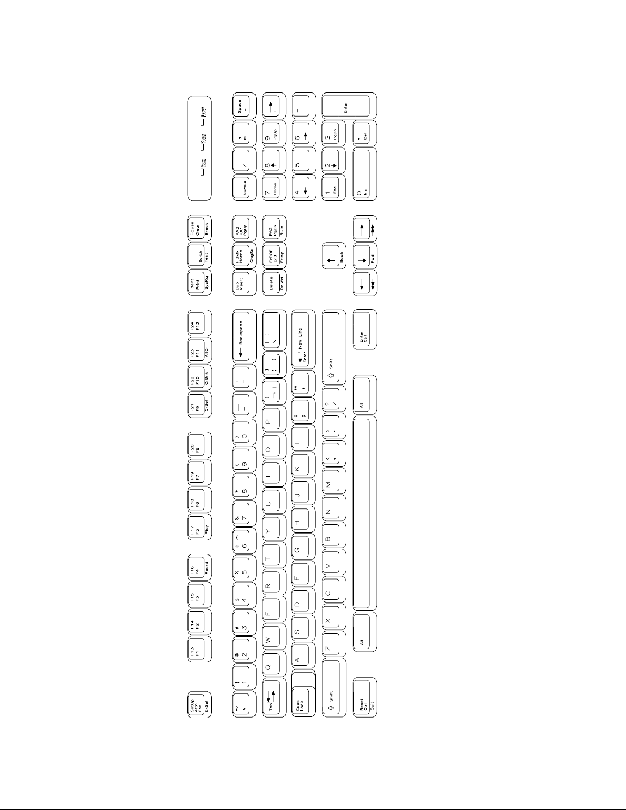
1480 CUT Emulator
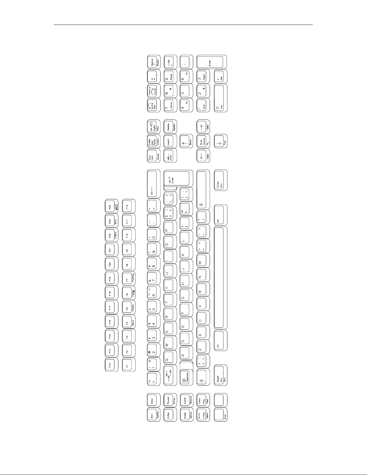
104-key Keyboard Layout
707042-002 6-7
Page 46
1783 Network Computing Terminal User’s Manual
1480 CUT Emulator
122-key Keyboard Layout
6-8 707042-002
Page 47
Monitoring response time
At times you may be requested to assist in monitoring and analyzing the speed of system
response at your terminal, or you may wish to collect this data on your own.
Note: The attached controller must support this function.
To start the Response Time Monitor:
1. Press the ExSel key
2. Press the F19 key.
To stop the Response Time Monitor, repeat the sequence above.
Configuring the 1480 CUT Emulator
The configuration function enables the environment to be set up to suit your needs and
work habits while working in CUT emulation mode.
Defining and selecting features
Chapter 6: 1480 CUT emulator
To bring up the 1480 CUT Emulator configuration screen:
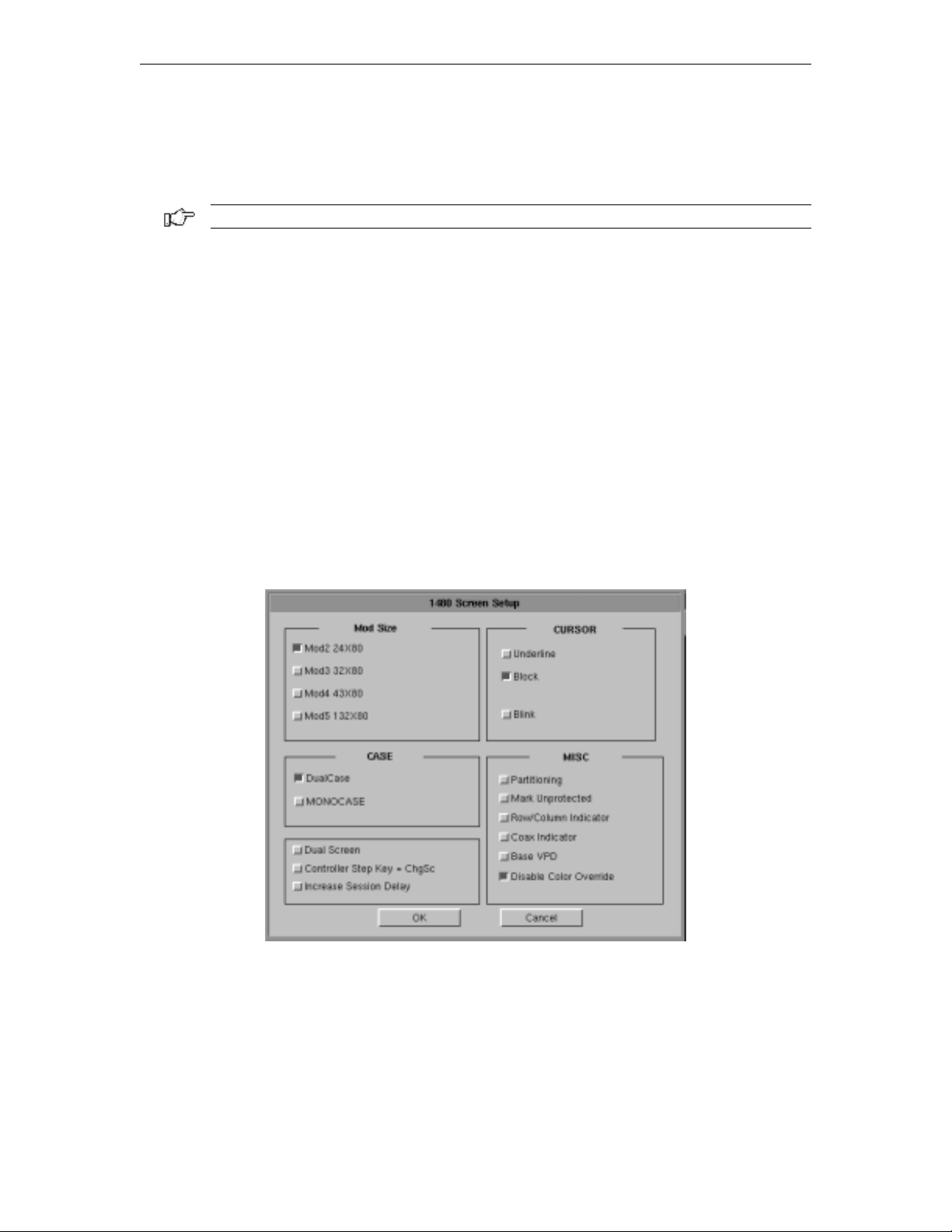
1. Click Setup to open the 1480 Setup menu.
2. Click Screen. The 1480 Screen Setup screen is shown below:
• Mod Size – Select the mod required by the design of the application program.
Applications are designed to use one of the above mods, based on the number of rows
per screen and characters per row, respectively. The default is Mod 2.
• Case – Select DualCase for upper and lower case characters. Select MONOCASE
for all characters displayed as upper case letters.
• Cursor – Choose either an underline cursor or a block cursor. Select Blink for a
blinking cursor.
707042-002 6-9
Page 48

1783 Network Computing Terminal User’s Manual
• Partitioning – This feature is not currently implemented.
• Mark Unprotected – Select to display a special symbol in each unprotected field on
the screen. This enables you to recognize locations where keystrokes can be entered.
• Row/Column Indicator – Select to display the current cursor location on the operator
status row. Note that the location is determined by the application program on the host
system.
• Coax Indicator – Select to turn the coax indicator on. When this feature is on:
– A filled circle is displayed in position 71 of the status row to indicate an active
coax line.
– An open circle indicates no coax activity.
– A blinking circle indicates the very slow poll cycle of a coax line being
disconnected then reconnected. In that case, power down the 1783 NCT unit for
at least 10 seconds before turning the power on to reestablish communications,
or use the 1480 Miscellaneous Menu described later in this chapter.
The coax indicator overrides other status line information in position 71 because it is
normally used as a diagnostic feature.
• Base VPD – Select to enable the basic Vital Product Data functionality.
• Disable Color Override – Normal base color supports four colors - blue, green, red
and white. A command from the controller can force the display to two base colors,
green and white. Enabling this button causes the 1480 emulator to ignore the controller
command and to display all four base colors.
• DualScreen – Enables the 1480 DualScreen feature. (See Configuring Dual Screen
Mode later in this chapter for details on this and the following two options.)
• Controller Step Key = ChgSc – Enables Alt - ChgSc as the controller session
step key.
• Increase Session Delay – Increases the delay between changing sessions.
6-10 707042-002
Page 49
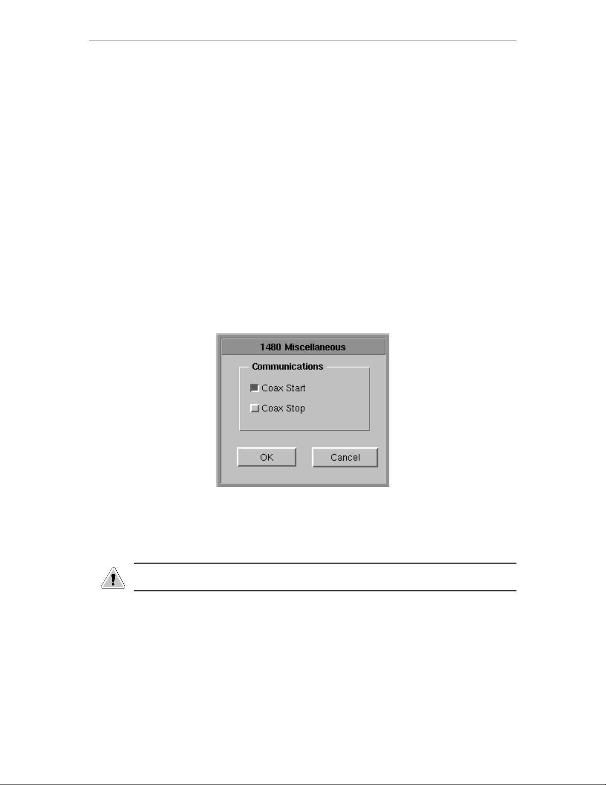
1480 Miscellaneous
Normally the 1480 emulator is running with the coax communications active over the
coaxial cable to the mainframe host controller. For instances where the user may want to
change a configuration item such as keyboard type (104 to 122) or mod size (Mod 2 to
Mod 4), this screen provides the ability to make modifications to the emulator without
powering off the 1783 NCT and then powering it back on.
The user may make all the desired menu changes first. Some of the menu items such as
the two mentioned previously only take effect during the initial exchange of data with the
controller.
Restarting the 1480 Emulator
To setup a remote host:
1. Click Setup in the upper left-hand corner of the screen to open the 1480 Setup menu.
2. Click Miscellaneous. The 1480 Miscellaneous screen is shown below.
Chapter 6: 1480 CUT emulator
3. Click Coax Stop.
4. Click the OK button. This stops the 1480 from responding to the controller.
CAUTION: All data on the 1480 screen will be lost, along with the bridge data transfers
being stopped!
The 1480 screen data is erased and replaced by a large X. The operator symbol is placed
in the status row along with another X. This shows that the communications have been
halted.
5. Click Coax Start.
6. Click the OK button to restart the coax communications and initiate the exchange of
configuration items with the controller.
7. Click the Cancel button to exit this panel.
707042-002 6-11
Page 50
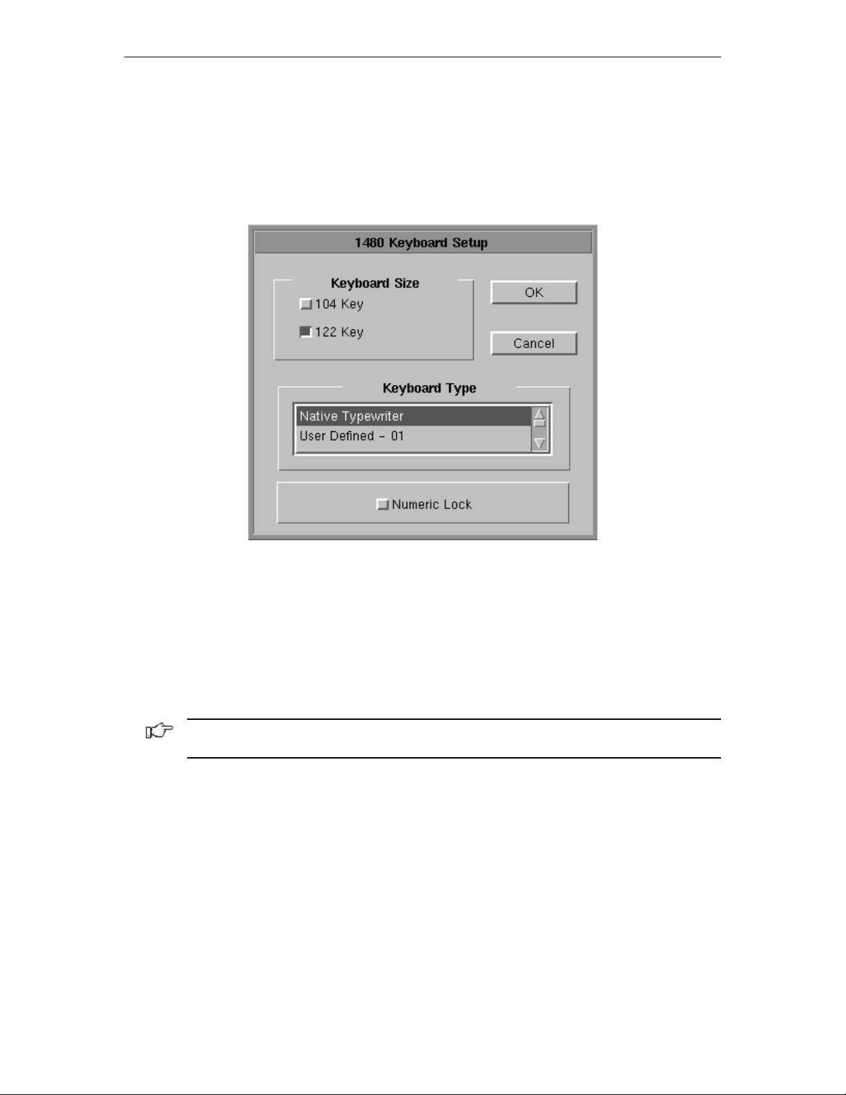
1783 Network Computing Terminal User’s Manual
Keyboard setup
To open the Keyboard Setup panel:
1. Click Setup to open the 1480 Setup menu.
2. Click Keyboard. The Keyboard Setup screen appears:
• Keyboard Size – Select either 104 or 122-key keyboard.
• Keyboard Type – Select type of keyboard.
• Numeric Lock – If supported by the server, will allow numeric keys only for numeric
fields.
Click OK to save the changes and exit the screen, or Cancel to discard the changes
and exit.
Note: If the keyboard size or type is changed, the coax must be stopped and restarted for
the changes to become effective.
6-12 707042-002
Page 51
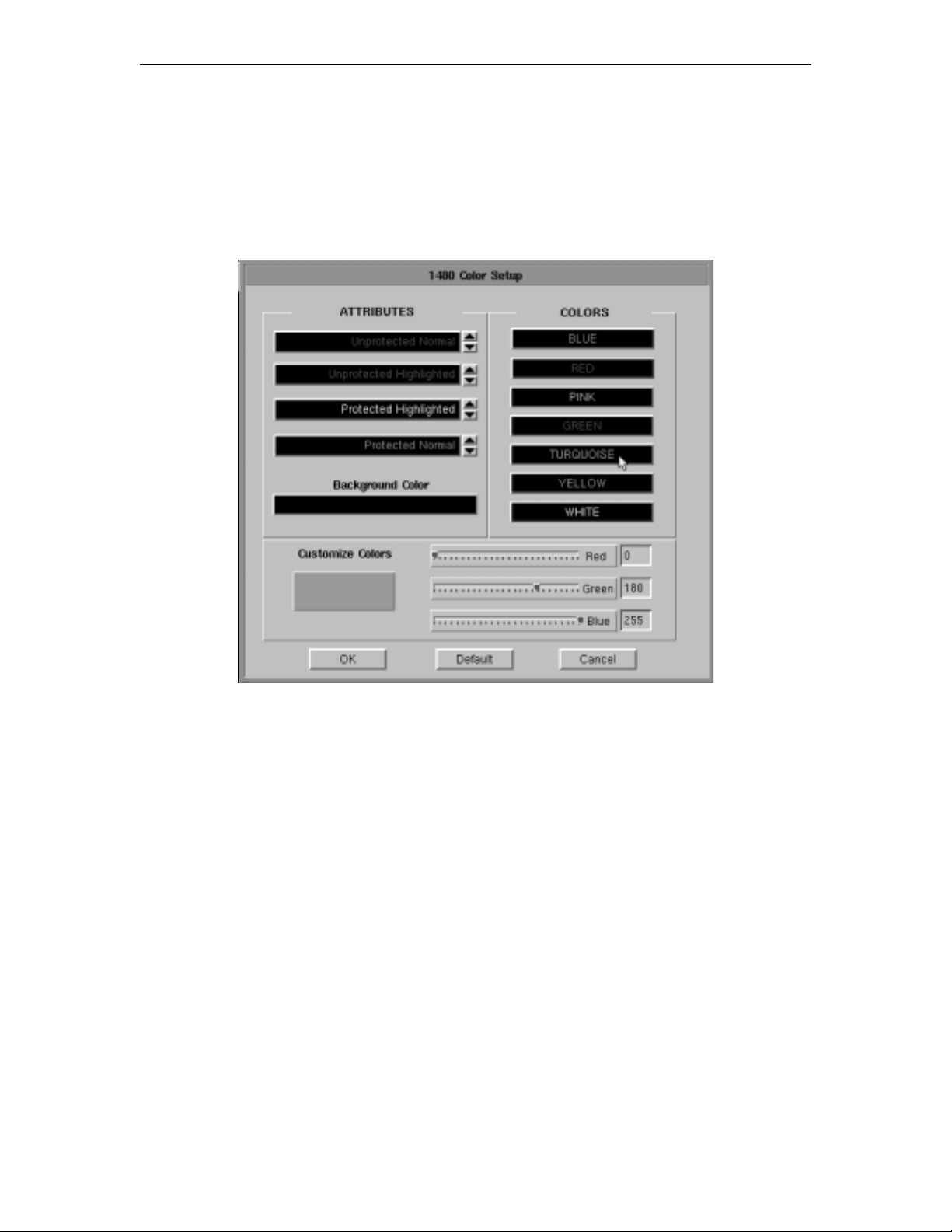
Color
To open the Color Setup Panel:
1. Click Setup to open the 1480 Setup menu.
2. Click Color. The Color Setup screen appears:
Chapter 6: 1480 CUT emulator
• Attributes – Use the arrows to select colors from the Colors list on the right. Select
for protected, unprotected, normal and highlighted fields.
• Background Color – Use any or all of the three slider bars until the desired color
shows in the Background Color box and as the background of the Color Setup screen.
• Customize Colors – Use any or all of the three slider bars to adjust the colors
showing on the Colors list.
Click OK to save the changes and exit the screen, Default to return to the system’s
default settings, or Cancel to discard changes and exit.
707042-002 6-13
Page 52
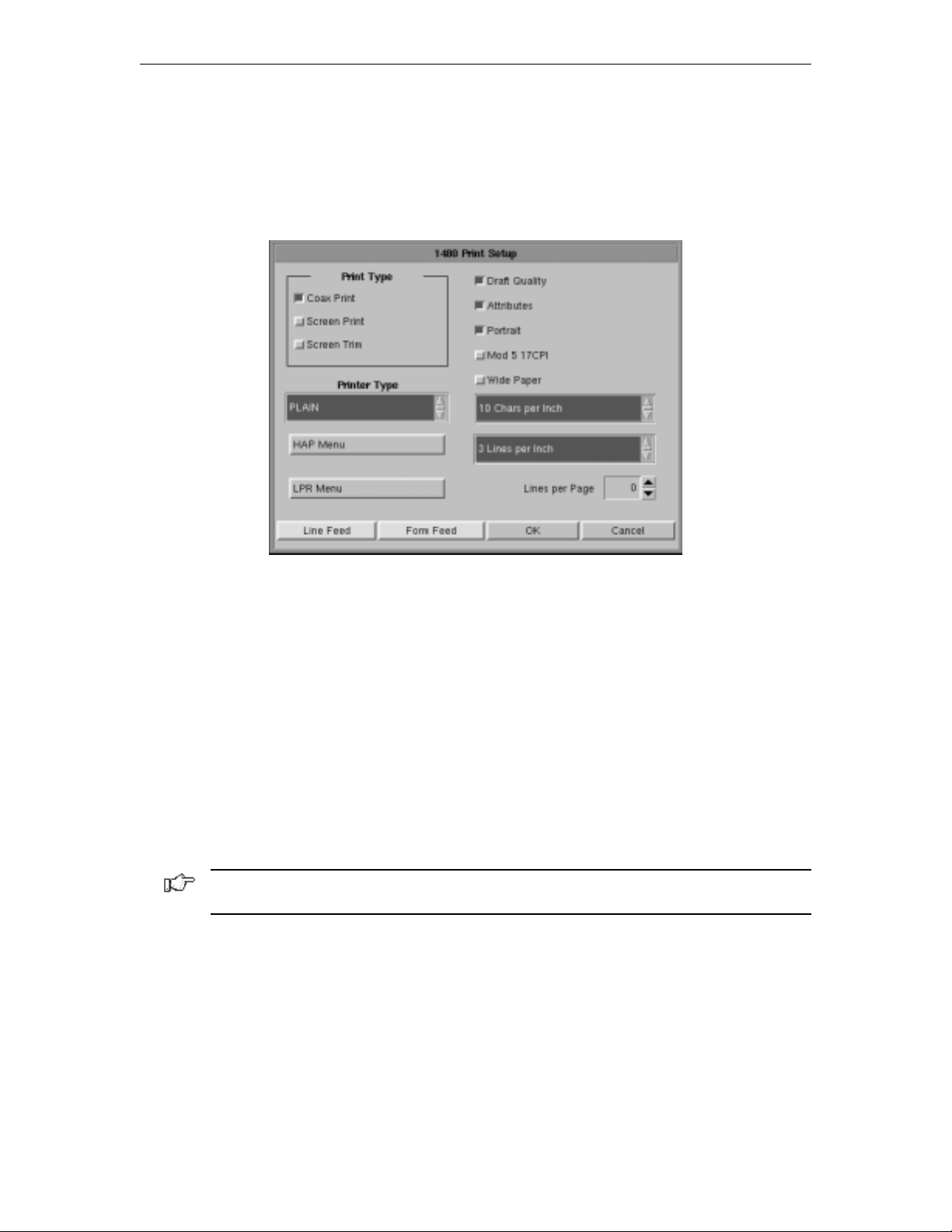
1783 Network Computing Terminal User’s Manual
Printer setup and printing
The 1480’s screen-print may be directed to either a local printer, a remote LAN printer, or
a coax printer. To initiate printing once printer setup is complete, press the Print key. To
access the Printer Setup screen (shown below) select Printer from the 1480 Setup menu.
Print type
• Coax Print – Sends the print request to the controller.
• Screen Print – Prints the entire contents of the application window.
• Screen Trim – Prints the user-selectable area within the application window. (This
feature is not currently implemented)
• Printer Type – Specifies the printer driver to use when printing. Options are:
– Plain
– HP Laserjet
– Epson Inkjet
– Proprinter
– Postscript
Note: Printing options found on this configuration panel may vary depending on the
printer type selected.
• Draft – Prints draft quality when selected. Otherwise printing is letter quality.
• Attributes – If selected, prints intensified characters as bold and underlined when
required.
• Portrait – If enabled, prints in Portrait mode. If disabled, prints in Landscape mode.
• Wide Paper – If enabled, allows printing of more than 80 characters per line. This
setting is generally used when Proprinter is selected as the Printer Type.
• CPI Selection – Specifies the number of Characters Per Inch to print. Options are
10, 10.5, 12, and 17 CPI.
6-14 707042-002
Page 53

Chapter 6: 1480 CUT emulator
• LPI Selection – Specifies the number of Lines Per Inch to print. Options are 3, 4, 6,
8, and 8.4 LPI.
• Lines per page – Specifies the number of Lines per Page to print. Selectable range
is 0-255.
• Line Feed – Sends an immediate Line Feed to the selected printer.
• Form Feed – Sends an immediate Form Feed to the selected printer
• HAP Menu – Displays the HAP configuration menu. The HAP menu button is gray
when HAP is disabled and green when enabled.
• LPR Menu – Displays the LPR configuration menu. The LPR menu button is gray
when LPR is disabled and green when enabled.
Coax printer assignment
To see how the 1480 printer is currently assigned, press Alt - Ident. The Assign Printer
condition symbol (
) will display on the operator status row.
:lobmysnoitidnocretnirPngissA:retnirpepytsihtsetacidnI
XX
_ _
To assign or change a Coax printer:
1. Consult your supervisor for an available coax printer’s ID number.
2. Enter the two-digit number. The two-digit number replaces the underscore positions,
or the assigned coax printer’s ID number, on the operator status row.
Once the printer’s ID number is entered, the sequence ends automatically.
If an invalid ID number is entered for a coax printer, the “What?” symbol (X ?+) appears
on the operator status row. If this occurs, press Reset and try another number.
>>>.e.i(M
C C 1 0 0 8 )
dengissanu,xaoC
rebmunDIs’retnirpehtsixxerehw,xaoC
707042-002 6-15
Page 54
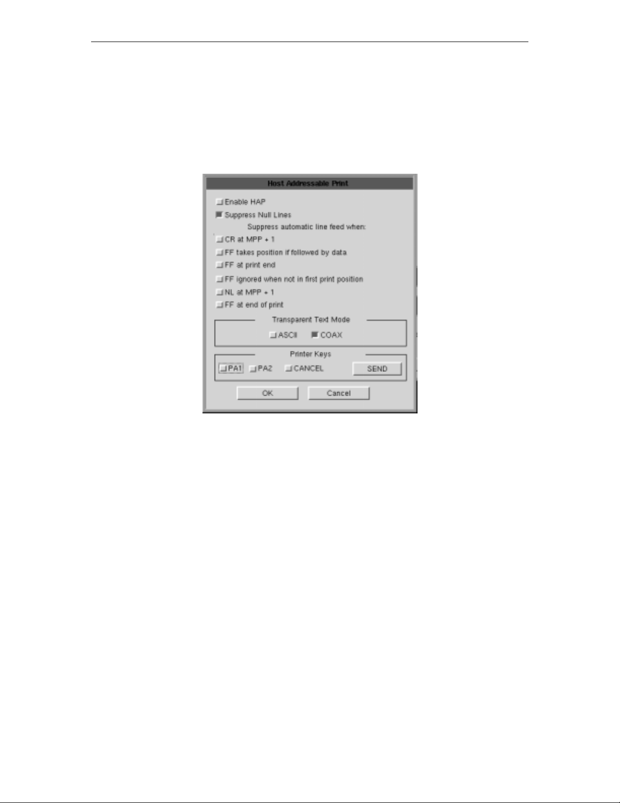
1783 Network Computing Terminal User’s Manual
HAP Menu
The Host Addressable Print feature enables the host to send print requests to the 1783’s
attached printer. LU2 (screen) prints are always formatted by the display according to the
printer menu selections. To enable or disable HAP, click the HAP Menu button from
within the 1480 Print Setup Screen. The Host Addressable Print configuration screen will
appear:
• Enable HAP – Select to enable the HAP feature.
• Suppress Null Lines – Selection of this item will cause null lines to be removed
from formatted (40/64/80 CPI) HAP LU3 prints. Null lines are lines that contain only
non-printable characters (such as nulls, attributes or alphanumeric characters in a nonprint field).
• Suppress automatic line feed when:
– CR at MPP + 1 – If this option is selected, when the printer reaches the
Maximum Print Position + 1 (the end of the print line), the carriage returns to the
beginning of the line without a line feed. The next printed characters will overwrite
the current line of printed characters. If this option is not selected, (the default),
when the printer reaches the end of the line, the carriage returns to the beginning
of the line and drops down one line.
– NL at MPP + 1 – If this option is selected, the printer does not execute a line
feed if there is a new line command at the Maximum Print Position + 1 (the end
of the print line). The printer begins printing on the next line. If this option is not
selected (the default), when the printer reaches the end of the line, it executes two
line feeds.
– FF at print end – If this option is selected, the printer does not execute a line
feed after a form feed. If this option is not selected (the default), the printer
executes a line feed after a form feed. Characters printed on the new page begin
on the second line.
6-16 707042-002
Page 55

Chapter 6: 1480 CUT emulator
• FF ignored when not in first print position – If this option is selected, a form
feed character in the first position or next to the maximum print position is executed
while form feed commands in any other positions are printed as blank characters and
are otherwise ignored. If this option is not selected, all form feed commands are
executed.
• FF takes position if followed by data – If this option is selected, and if the form
feed character is not at the end of the print data, a form feed is executed and a blank
character is printed in the first position on the next page. Subsequent printing starts in
the second position on the new page. If this option is not selected, the form feed
character is not printed as a blank character and subsequent printing starts in the first
position on the new page.
• FF at end of print – If this option is selected, the printer ejects the last printed page
and subsequent printing begins on the new page. If this option is not selected, the last
page is not ejected and a line feed is executed. Subsequent printing begins on the new
line of the current page.
• Transparent Text Mode
– Coax – data included in an SCS Transparent Mode command (35H) is printed in
the LU1 environment as follows:
• Valid EBCDIC characters are translated and printed normally.
• Invalid EBCDIC characters (SNA character string [SCS] commands) are
printed as hyphens.
– ASCII – all data included in the command is sent through to the printer
untranslated. The following setup values are not sent to the printer during
initialization:
• Chars/Inch
• Lines/Inch
• Quality
• Printer Keys – Allow the operator to send either a PA1, PA2, or Cancel to the
application. The operator selects one of the functions (PA1, PA2, or Cancel) and
then clicks the SEND button. (Cancel is effective only in LU1 type print sessions.)
Click OK to save the changes and exit the screen, or Cancel to discard the changes
and exit.
Note: For changes to the HAP Menu to become effective, the 1480 must be restarted via
the Miscellaneous Menu, or by turning the unit off and back on again.
707042-002 6-17
Page 56
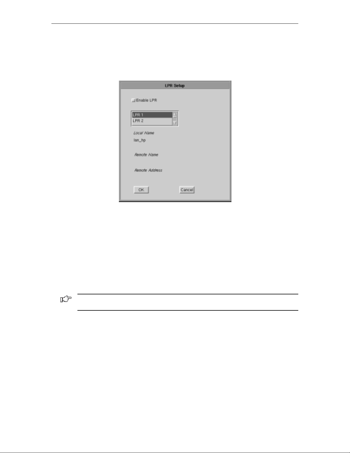
1783 Network Computing Terminal User’s Manual
LPR Menu
To configure LPR, select the LPR Menu button from within the 1480 Print Setup Screen.
The LPR Setup panel is shown below:
• Enable LPR – Select to enable LPR printing.
• LPR scroll window – used to select an LPR printer. A blue background indicates
the printer is selected.
• Local Name – User-defined name of the printer.
• Remote Name – Queue name that print jobs are sent to from an LPR-enabled device.
• Remote Address –IP address of the selected printer.
Click OK to save the changes and exit the screen, or Cancel to discard the changes
and exit.
Note: For changes to the LPR Menu to become effective, the 1480 must be restarted via
the Miscellaneous Menu, or by turning the unit off and back on again.
6-18 707042-002
Page 57

Dual Screen feature
The 1783 dual screen feature is provided by a special software program on the main logic
board. With the 1783 NCT Display Station in 1480 Emulation mode, you can display and
operate two sessions on one monitor in either a side-by-side format or a zoomed session
(that is, one of the two sessions occupies the entire display surface and you toggle between
the two sessions). Fields can also be copied from one session to the other. Dual screen
sessions are supported on a display configured as a Mod 2, 3, or 4.
Configuration requirements
To support Dual Screen mode, the controller must be configured for two or more logical
sessions on the display terminal’s port. In addition, PC File Transfer mode must be set for
those ports that use the Mark/Paste function of the 1783.
The 1783 must be configured as follows to be able to exercise the enhanced dual
screen features:
• The NCT 1480 Emulator must be in either Mod 2, 3, or 4 mode with Partitioning
deselected. (See Chapter 6: Defining and Selecting Features.)
• Host Addressable Printing must be disabled.
• The 1783 must be configured for video mode of 1024 x 768. (See Chapter 11:
Configuring NCT Miscellaneous.)
Chapter 6: 1480 CUT emulator
Note: Only 122-key keyboards are supported.
The light pen is NOT supported in Dual Screen mode.
Configuring Dual Screen mode
From the 1480 CUT Emulator application:
1. Click Setup to open the 1480 Setup menu.
2. Click Screen.
3. Click the Dual Screen button (a green button indicates that Dual Screen mode
is enabled).
4. If the Controller Session Step Key is Alt - ChgSc (most 3174’s), click the Controller
Step Key button to enable it. If the controller is configured for the Session Step Key
to be Alt - Insert (most 1174’s will be configured this way) DO NOT click on the
Controller Step Key button.
5. Click OK to save changes.
Note: If later operation of Jump and Swap keys seem to not work correctly every time,
there may be a need to increase the delay between changing sessions. Click the Increase
Session Delay button to enable it.
707042-002 6-19
Page 58
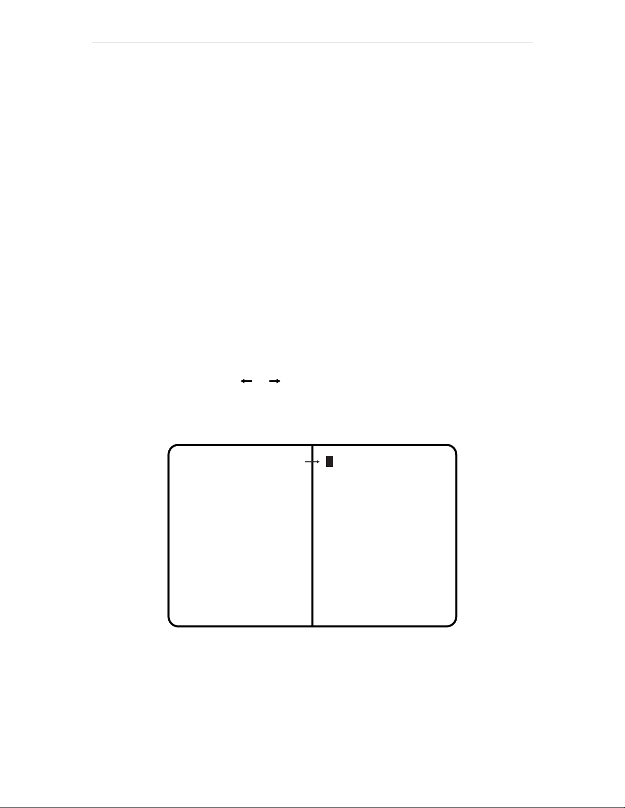
1783 Network Computing Terminal User’s Manual
Starting Dual Screen mode
After enabling Dual Screen mode the first time, the 1480 emulator will need to be restarted.
From the 1480 CUT Emulator application:
1. Click Setup.
2. Click Miscellaneous to open the 1480 Miscellaneous screen.
3. Click Coax Stop.
4. Click OK.
5. Click Start.
6. Click OK. The coax data should appear in approximately 3 seconds (13 seconds if
Increase Session Delay is enabled).
7. Click Cancel to close the 1480 Miscellaneous panel.
8. Close the 1480 CUT Emulator application. When it is reopened, there should be a
display with two sessions of data side by side.
Active and Suspended Screens
Dual Screen mode can be used to simultaneously display two host sessions. Because two
or more sessions must be managed, one session is selected as the active session and the
other as the inactive or suspended session.
A highlighted arrow ( or ) is displayed on the separator line at the cursor row to
help find the cursor and point to the active session.
Two Sessions in Side-by-Side Format
Session 1
(Inactive Session)
Session 2
(Active Session)
6-20 707042-002
Page 59
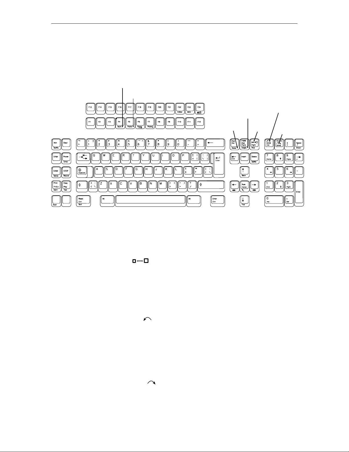
Key assignments
Only the 122-key keyboard is supported for Dual Screen mode.
122-Key Dual Screen Keyboard Keys
Mark
Paste
Chapter 6: 1480 CUT emulator
Select
Step
Session
Left
Dual Screen Mode enhancements
The following commands and features are available in Dual Screen mode.
Zoom
Press the Zoom key ( ) to alternate the display between unzoomed (side-by-side)
format and zoomed (normal) format. The zoomed format is identical to the standard Mod
2, 3, or 4 format. There is only one unzoomed format for all three model types.
The zoomed session is always the currently active session. When the terminal is unzoomed,
both sessions are displayed.
Swap
Zoom
Select Right
Select left
Press the Select Left key ( ) to position the cursor in the session on the left side of the
display when the display is in side-by-side format. The Select Left key operates in zoom
and side-by-side modes. The session on the left side is now the active session and receives
immediate screen updates. The session on the right side is “frozen,” which means it does
not display new screen updates until it becomes the active session. The Select Left key has
no effect if the left side session is already active.
Select right
Press the Select Right key ( ) to position the cursor in the session on the right side of
the display when the display is in side-by-side format. The Select Right key operates in
zoom and side-by-side modes. The session on the right side is now the active session and
receives immediate screen updates. The session on the left side is “frozen,” which means
707042-002 6-21
Page 60
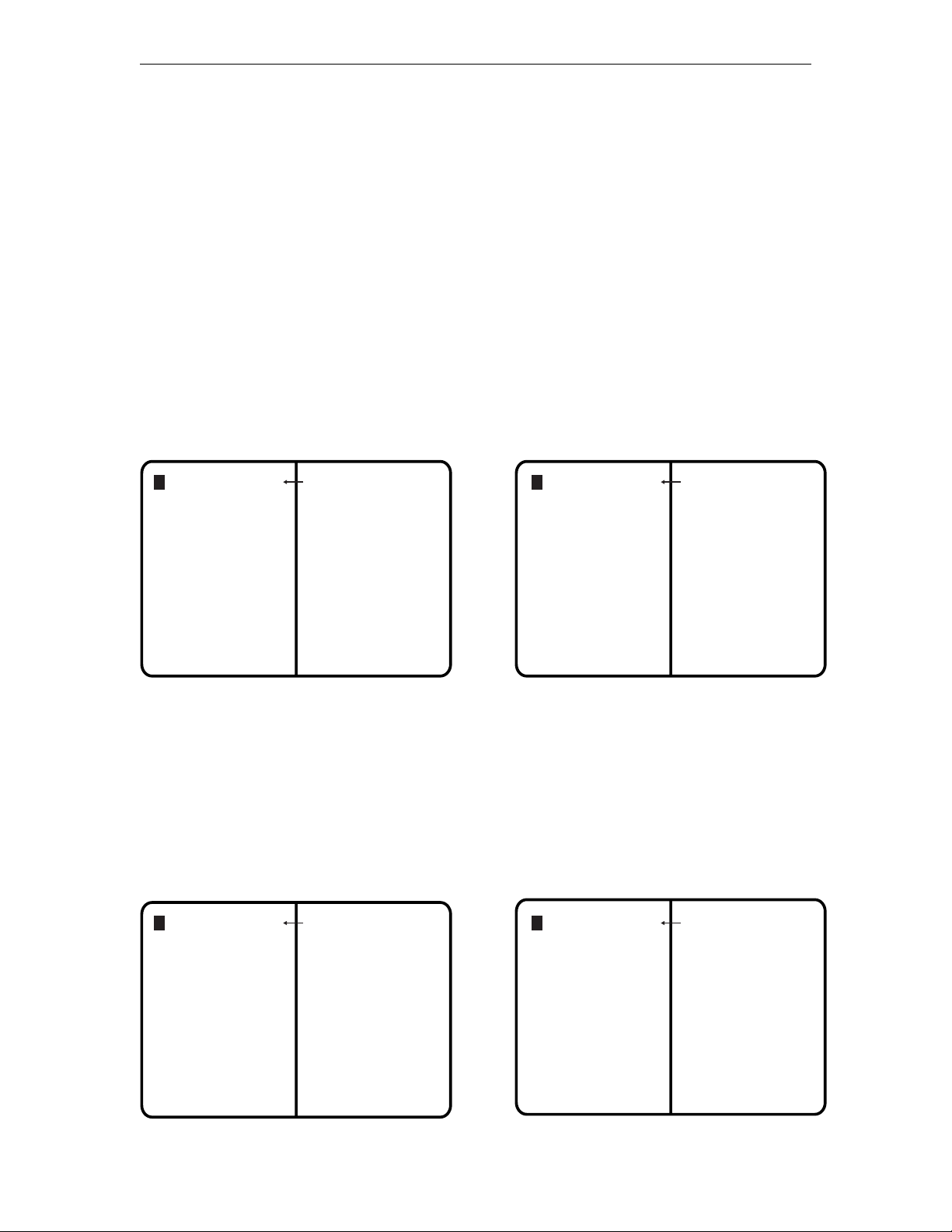
1783 Network Computing Terminal User’s Manual
it does not display new screen updates until it becomes the active session. The Select
Right key has no effect if the right side session is already active.
Step Active session
Press and hold the Alt key while pressing the ChgSc key to change the active session to
make the next highest session the active session. The cursor does not change sides and the
session that is not selected is not affected.
For example, suppose three sessions are available. If Session 2 is the active session (the
cursor is in Session 2) and is on the left and Session 1 is on the right, press the Alt - ChgSc
key combination to increment the left side to Session 3. Session 3 displays on the left side
and has the cursor. Session 1 is still on the right side. If the Select Right key is pressed,
Session 3 is still displayed on the left and Session 1 is still displayed on the right, but now
Session 1 has the cursor.
Example of Step Active Session
Session 1
(active session)
Session 2
(inactive session)
Session 2
(active session)
Session 1
(inactive session)
Swap session
Press and hold the Alt key while pressing the Swap key to switch sessions without moving
the cursor. For example, in side-by-side mode, if the left session is the active session (and
has the cursor), press the Alt - Swap key combination to move the left session to the right
and the right session to the left. The session on the left is still the active session and has
the cursor.
Example of Swap Session
Session 2
(active session)
Session 1
(inactive session)
Session 3
(active session)
Session 1
(inactive session)
6-22 707042-002
Page 61

Chapter 6: 1480 CUT emulator
Mark
To select a field as the source field for a subsequent paste operation, position the cursor
anywhere within the field and hold down the Alt key while pressing the F4 key (Mark).
See Mark/Paste below for a complete description.
Paste
To select a field as the target field and paste source data into that field, move the cursor to
the target field and hold the Alt key while pressing the F5 key (Paste). The data in the
source field is pasted into the target field. If there is already data in the target field, that
data is overwritten with the data from the source field. See Mark, above, for instructions
on how to select a source field. The target field cannot be in the same session as the
source field. See Mark/Paste below for additional information about mark and paste.
Mark/Paste
Use the Mark/Paste feature to copy data between sessions. With this feature, data can
quickly be marked and pasted between fields in different sessions.
Mark field
The mark field is the field highlighted as the source data field. The data to be pasted must
be within a displayed field. Data cannot be marked for pasting if it is in a nondisplayable
field. Data can be pasted from protected as well as unprotected fields. The mark field
must be selected before selecting the paste field.
To select the source or mark field, position the cursor anywhere within the field, then
press and hold down the Alt key while pressing the F4 key (Mark). The field is displayed
in reverse video to indicate it is selected. If the Mark key is pressed while a field is
already selected, the selected field is deselected. The field is also deselected after one of
the Paste keys is pressed or if the session with the selected field is reselected with the
Select Right or Select Left key. A session with a selected field is frozen and does not
receive coax updates.
After selecting a field as the source or mark field, use the Select Left or Select Right key
to make the opposite session the active session, then move the cursor to the target field.
Paste field
The paste field is the field that receives the data from the mark field and it cannot be in the
same session as the mark field. The field that receives the pasted data must be an
unprotected field. Standard data truncation rules apply when the paste and mark fields are
of different lengths. If the paste field is longer than the mark field, data is replaced in the
paste field only up to the length of the mark field. If the paste field is shorter than the
mark field, data is truncated up to the length of the paste field. The data that has been
pasted is temporary until an Aid key (Enter or F key) is pressed; if a Select Right or Select
Left key is pressed before an Aid key, the pasted data is lost.
707042-002 6-23
Page 62

1783 Network Computing Terminal User’s Manual
Walk through
The following is an example of how to start a dual screen after configuring the 1783 NCT
as described on page 6-19, Configuring Dual Screen Mode, and after following the
instructions for Starting Dual Screen Mode on page 6-20.
1. Press the Zoom (
The cursor is displayed on the right side of the screen. The session on the right is
now the active session.
2. Press the Select Left ( ) key.
The cursor is displayed on the left side of the screen. The session on the left is now
the active session.
3. Log on to a host application using the session on the left side of the display.
4. Press the Zoom (
The display consists of a standard, one-session format.
5. Press the Select Right (
The session from the right side of the display becomes the active session. The
screen is still zoomed and the right session is the only session displayed.
6. Log on to a host application using the selected right session, which is the only
session displayed. While the logon is processing, go to Step 7.
7. Press the Zoom (
The display unzooms and consists of the side-by-side format. Wait for logon
processing to complete.
) key to display two side-by-side sessions.
) key.
) key.
) key.
Screen Print mode
Follow these steps to perform a screen print in Dual Screen mode:
1. Position on the left the session to be printed, using the Swap and/or Step keys if
needed.
2. Print the screen using the normal screen print commands.
6-24 707042-002
Page 63

Chapter 7
1490 Twinax Emulator
In this Chapter...
Standard features
Communication Set Up
Screen Setup
Color Setup
Print Setup
Miscellaneous
Page 64

1783 Network Computing Terminal User’s Manual
The 1490 Twinax Emulator is designed to provide a wide range of functions and
applications. Data messages are communicated between the emulator and the System/3X
or AS/400 through a twinax cable up to 1500 meters long. The 1783 equipped with a
1490 emulator can be attached to any of the following processors and control units:
• IBM System/36
• IBM System/38
• IBM 5394 Control Unit
• IBM 5494 Control Unit
• IBM AS/400
The 1490 supports 122-key and 104-key keyboards..
You can generate hard copy by attaching a twinax printer to the System/3X or AS/400 or
by attaching a host addressable printer to the 1783 equipped with a 1490 emulator. The
Local Screen Print feature enables you to make a hard copy of the displayed text.
Standard Features
• Multiple Emulations – The 1490 can emulate several different display types. Both
monochrome and color displays can be emulated. For display stations attached to a
System/36 or System/38, a 132-column color format can be selected.
• Two-Host Sessions – You can configure one host display sessions and one printer
host session that run concurrently.
• Full-Screen Setup Menus – The full-screen setup menus offer simplicity and ease
of use for all setup functions.
• User Selectable Color Mixing – With the color 1490, you can select the shades of
the colors for the attributes.
• Audible Alarm – Sounds when the host system signals the display station.
• MVP (Multivendor printers) – The 1490 supports a wide variety of industry standard
printers.
• Optional Features
• US English
– 104-Key EBCDIC US English Typewriter
– 122-Key 5250 US English Typewriter
– 122-Key 3270 US English Typewriter
707042-0027-2
Page 65
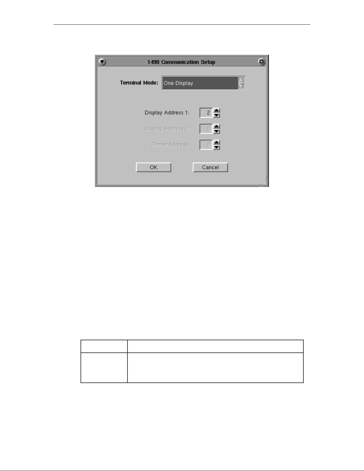
Communication Setup
Chapter 7: 1490 Twinax Emulator
Terminal Mode
Consult the system operator before changing this option.
The 1783 in 1490 mode can operate in two different terminal modes. By enabling up to
two independent host sessions to be configured, each with a different address on the
system, multiple host functions can be active simultaneously.
• One-Display – The 1490 operates as a single display station with one address. This
is the default setting. Local screen printing is available.
• One-Display-Printer – Both the display and attached printer are logically connected
to the host, each having a different address. In this mode, host addressable printing is
enabled.
Display Address
The display address is the display station’s logical address on the System/3X or AS/400
port. Ask the system supervisor for this address. The 1490 will not operate online until
you enter this address. No default address is set at the factory.
noitceleSnoitpircseD
60hguorht00
morfsserddanatceleS 00 hguorht 60 emasehtngissatonoD.
.retnirpadnayalpsidarofsserdda
707042-002 7-3
Page 66
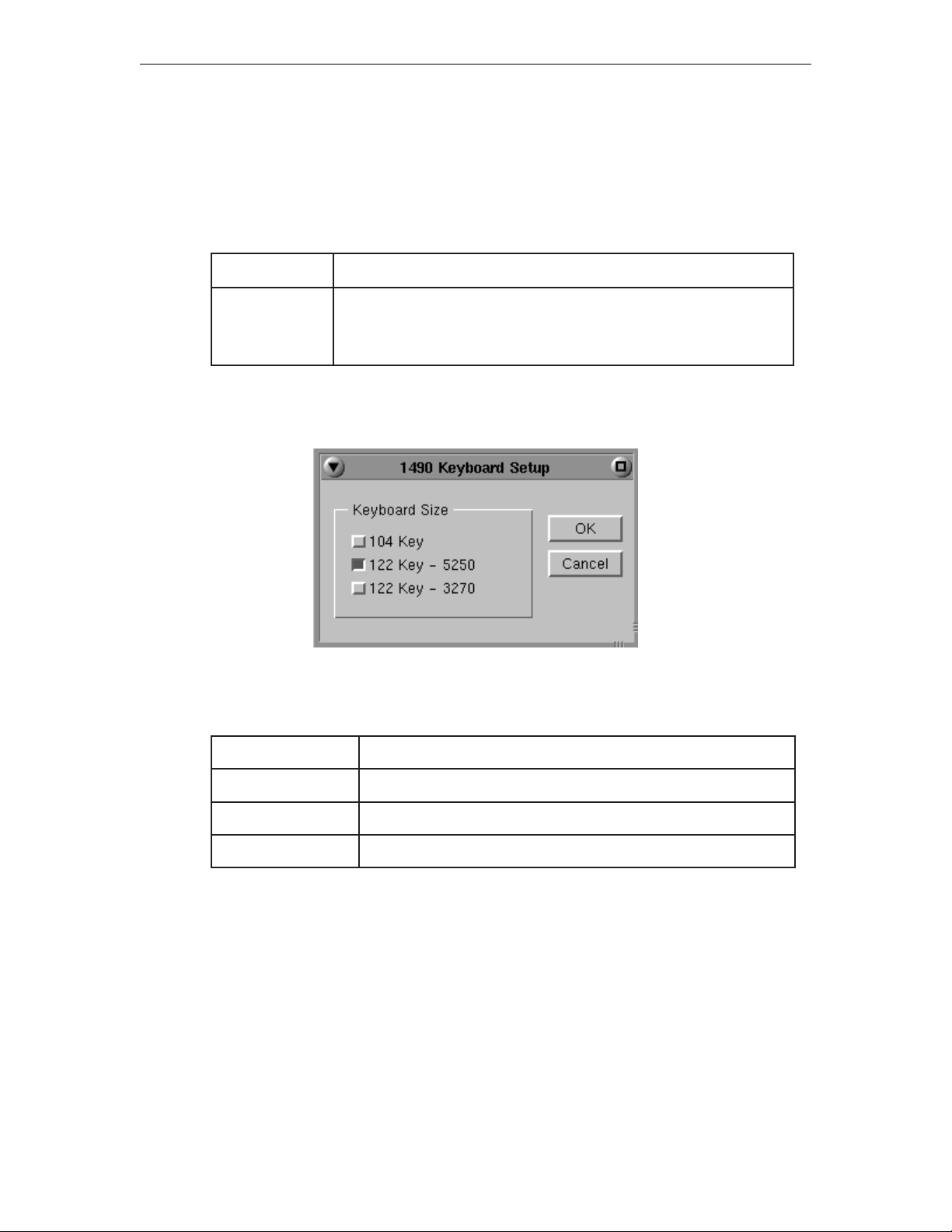
1783 Network Computing Terminal User’s Manual
Printer Address
The printer address is the printer’s logical address on the twinaxial cable originating
at the System/3X or AS/400. No default address is set at the factory. Ask the system
supervisor for this address. This option is available only if the display station is
operating in One-Display-Printer mode.
noitceleSnoitpircseD
Keyboard Setup
Use the following table to determine which keyboard you have.
60hguorht00
draobyeKnoitpircseD
morfsserddanatceleS 00 hguorht 60 emasehtngissatonoD.
.retnirpadnayalpsidarofsserdda
401.5-7egapmargaiddraobyekeeS
0525-221.6-7egapmargaiddraobyekeeS
0723-221.7-7egapmargaiddraobyekeeS
707042-0027-4
Page 67
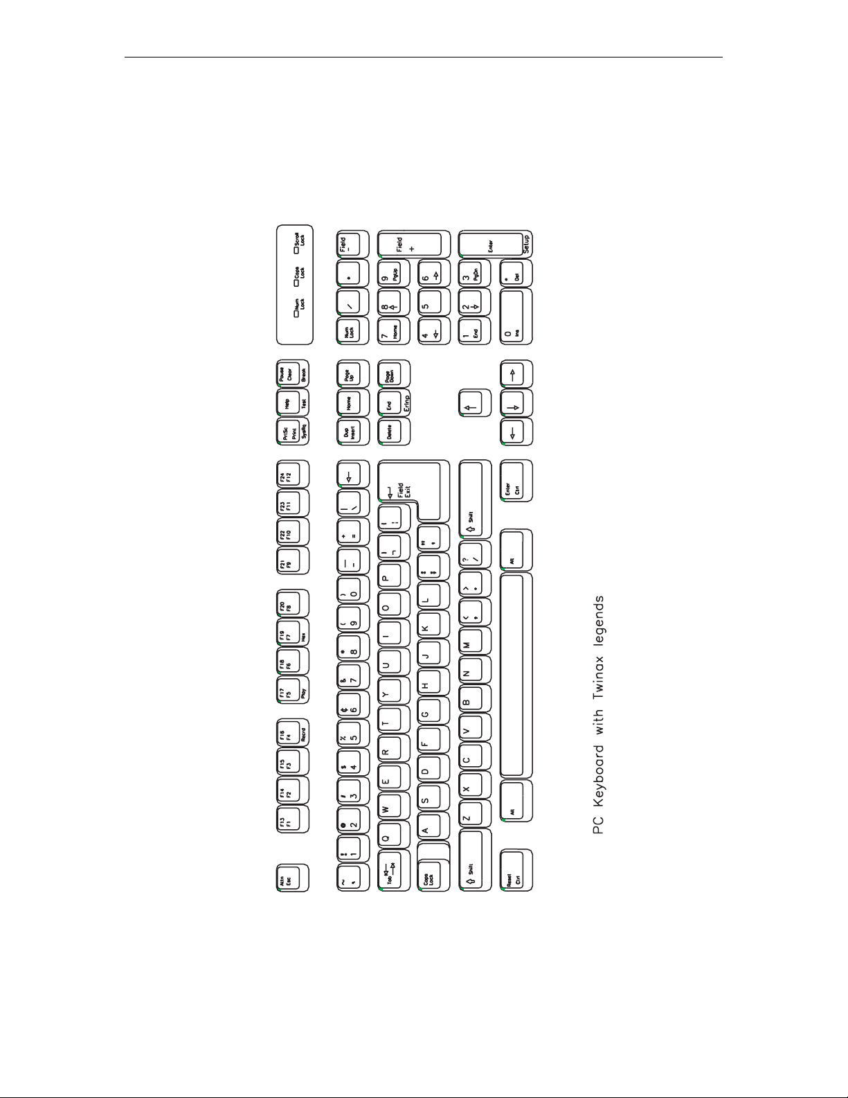
Chapter 7: 1490 Twinax Emulator
707042-002 7-5
Page 68
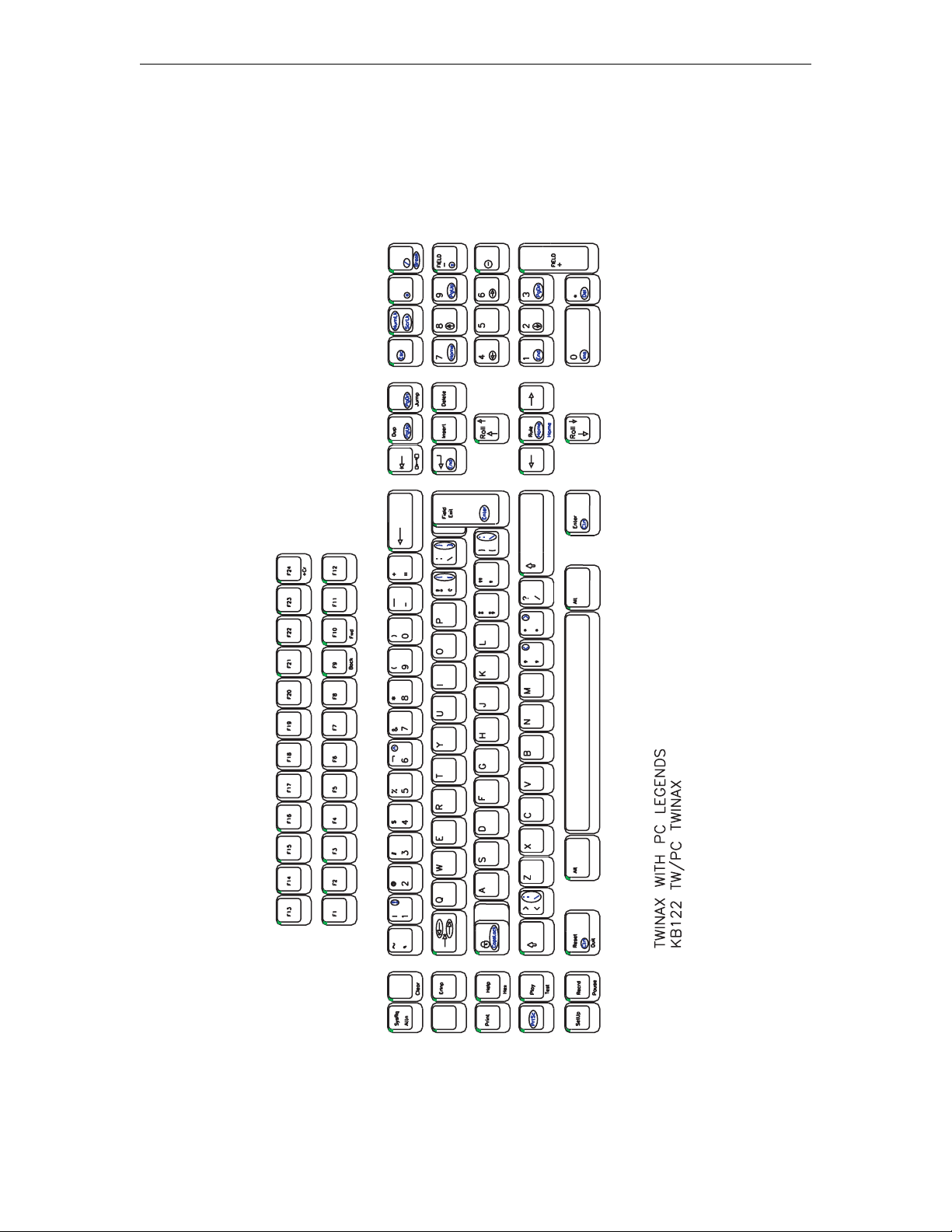
1783 Network Computing Terminal User’s Manual
707042-0027-6
Page 69
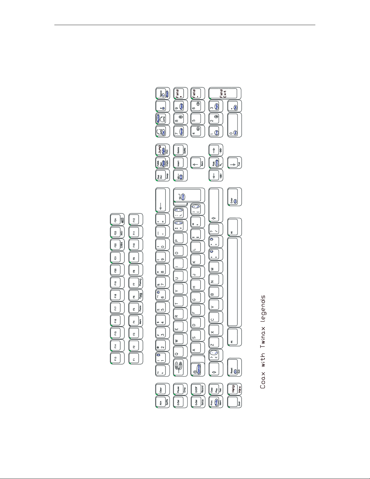
Chapter 7: 1490 Twinax Emulator
707042-002 7-7
Page 70
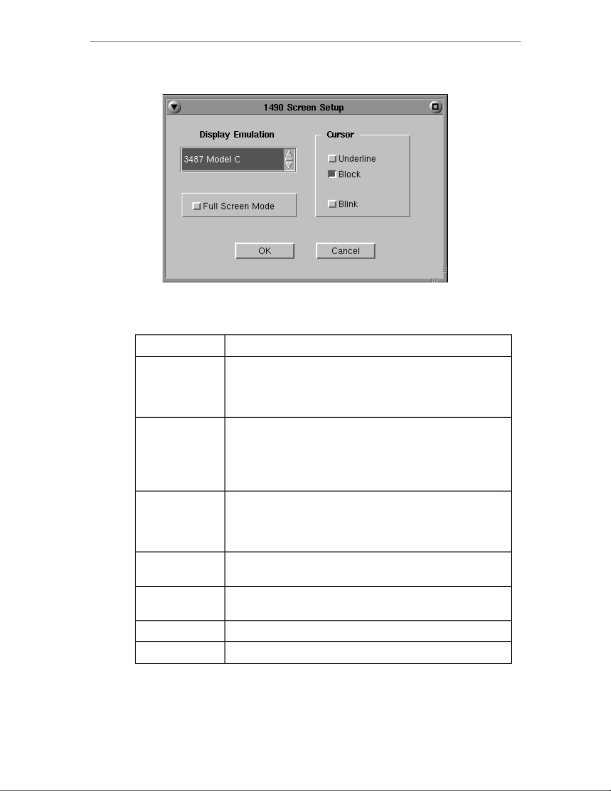
1783 Network Computing Terminal User’s Manual
Screen Setup
Display Emulation
noitceleSnoitpircseD
dednetxEstroppusnoitalumesihT.yalpsidrolocnmuloc-231
CledoM7743
.srotinomrolochtiwylnoelbaliavasidnasrotinom
DledoM7743
.srotinomemorhconom
DledoM7913
2ledoM0813
.srotinomemorhconom
6913
2ledoM7913
CledoM7843.yalpsidrolocnmuloc-231
.srotinomrolocylno
.srotinomemorhconomdnarolochtob
noitstsyalpsidrofnoitalumesihttceleS.setubirttaretcarahc
rolocrofgnittestluafedehtsisihT.004/SAnaotdehcatta
stroppusnoitalumesihT.yalpsidemorhconomnmuloc231
yalpsidrofnoitalumesihttceleS.setubirttaretcarahCdednetxE
rofgnittesstluafedehtsisihT.004/SAnaotdehcattanoitats
dnarolochtobhtiwelbaliavasidnasrotinomemorhconom
esehtfoenotceleS.yalpsidemorhconomnmuloc-231
dehcattasnoitatsyalpsidroftroppusnmuloc-231rofsnoitalume
dnarolochtobhtiwelbaliavasinoitposihT.X3/metsySaot
htiwelbaliavasinoitposihT.yalpsidemorhconomnmuloc-08
htiwelbaliavasinoitposihT.yalpsidemorhconomnmuloc-08
GledoM7843.yalpsidemorhconomnmuloc-231
707042-0027-8
Page 71
Chapter 7: 1490 Twinax Emulator
By selecting one of the 132-column monochrome emulations, you can enable a 1490
display station attached to a System/3X to have 132-column capability, even though the
System/3X does not support 132-column color displays.
The Display Emulation option is also useful when installing and configuring devices
where system support services are not readily available (for example, at a remote site).
You can select the emulation of the display that is already configured on your system
without having to change the host configuration.
Cursor
noitceleSnoitpircseD
kcolB(kcolbastceleS
■
enilrednU.)_(rosrucenilrednunastceleS
knilB
.dilos
neercSlluF
Note: Underline and Block cursor mode are mutually exclusive.
Full Screen Mode
noitceleSnoitpircseD
neercSlluF
.gnittestluafedehtsisihT.)
sirosrucehtesiwrehtO.knilblliwrusrucehtdetcelesnehW
ehttaneddiheblliwrabunemehT.edomneercslluftceleS
ybneddihnuebnacrabunemehT.tesernorewoptxen
rodraobyekyek221anoyek"putes"ehtgnisserped
.draobyekyek401ano"retnedapyekciremun-tlA"
ehttaneddiheblliwrabunemehT.edomneercslluftceleS
ybneddihnuebnacrabunemehT.tesernorewoptxen
rodraobyekyek221anoyek"putes"ehtgnisserped
.draobyekyek401ano"retnedapyekciremun-tlA"
707042-002 7-9
Page 72
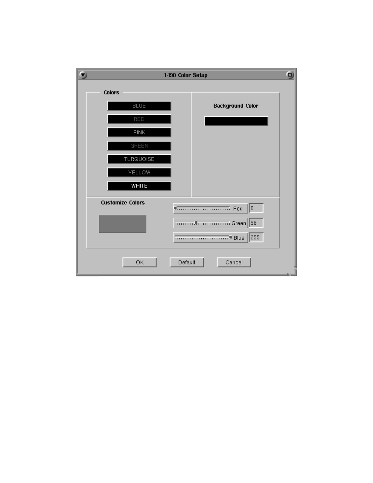
1783 Network Computing Terminal User’s Manual
Color Setup
• Colors – Use to select a color you desire as background or designated text.
• Background Color – Use any or all of the three slider bars until the desired color
shows in the Background Color box and as the background of this screen.
• Customize Colors – Use any or all three slider bars to adjust the colors showing on
the color list.
707042-0027-10
Page 73
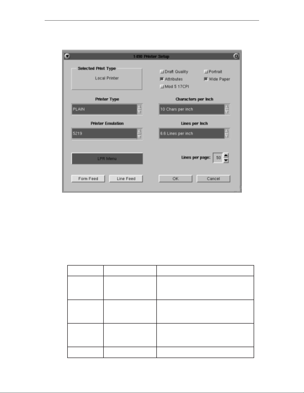
Printer Setup
Chapter 7: 1490 Twinax Emulator
The printer menu sets the printer parameters and controls the appearances of the
printed text.
The LPR menu can be used to direct the print to either a local or network printer. Screen
print and system print destinations are defined by this panel.
Attached Printer Type
The table below lists the printer type supported for each printer.
noitpOuneMsepytretnirP
,retnirporPMBI
II/I-ORP
RESAL-PH
QL-NOSPE
NIALP
ITT
dnaIIretnirporP
selbitapmoc
resaL,IIteJresaLPH
selbitapmocdnaIIteJ
seiresQLnospE
dnasretnirp
selbitapmoc
.gnittestluafed
.stnoftnedisernonfotroppus
.sretcarahclanoitanretni
rofderiuqersitroppusretcarahcdaolnwoD
ehtsisihT.sretcarahclanoitanretni
tnoftsebrofteslobmys8-namoRsesU
rofderiuqersegdirtractnoF.troppus
rofderiuqertroppusretcarahcdaolnwoD
707042-002 7-11
Page 74
1783 Network Computing Terminal User’s Manual
Printer Emulation
The table below lists the printer emulations supported for each printer type.
noitceleSepytretnirPnoitpircseD
9125
II-EGAP
RESAL-PH
tahtsksatgnissecorpdrowdetacitsihposrofdesU
,noitacifitsujcitamotua,noitcelestnoferiuqer
detroppuS.gnikirtsrevodnagninilrednu,gnidlob
toderiw-42decnavdadnasretnirpresalnoylno
.sretnirpxirtam
4124
6525
Characters per Inch
noitceleSnoitpircseD
71,21,01
5.01
Lines per Inch
II/I-ORP
RESAL-PH
QL-NOSPE
II/I-ORP
RESAL-PH
QL-NOSPE
.gnittestluafedehtsisihT.ytilauq
.snoitalumeretnirprehtoehttroppus
noitatumesihT.gnitnirpesopruplarenegrofdesU
,sretemarapgnitnirpemosfolortnocmetsysstroppus
tnirpdnahcnirepsenil,hcnirepsretcarahcsahcus
tonodtahtsmetsysrofgnitnirpcisabsedivorP
ehtrofhcnirepsretcarahc71ro21,01,eulavlaciremunatceleS
.sretnirplacolrofgnittestluafedehtsi01.ytisnedretcarahc
sihT.hcnirepsretcarahc5.01tadetnirpebottxetehtsecroF
.repap4Afoenilanodetnirpebotsretcarahc08selbane
noitceleSnoitpircseD
4.8,6.6,6,4,3
rof,hcnirepsenil4.8,6.6,6,4,3,eulavlaciremunatceleS
.sretnirplacolrofgnittestluafedehtsi6.ytisnedretcarahceht
707042-0027-12
Page 75
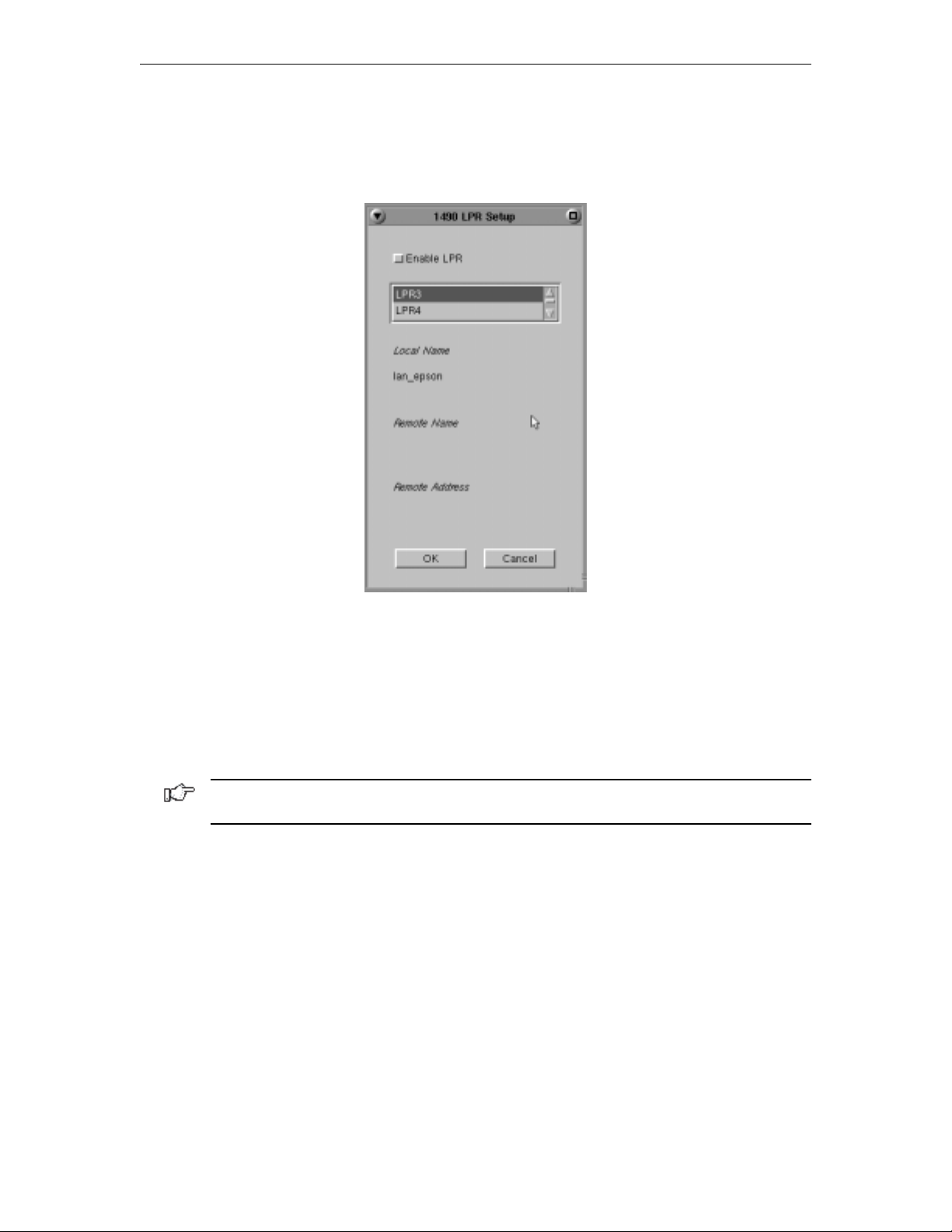
Chapter 7: 1490 Twinax Emulator
LPR Menu
To configure LPR, select the LPR Menu button from within the 1490 Printer Setup
Screen. The LPR Setup panel is shown below:
• Enable LPR – Select to enable LPR printing.
• LPR scroll window – used to select an LPR printer. A blue background indicates
the printer is selected.
• Local Name – User-defined name of the printer.
• Remote Name – Queue name that print jobs are sent to from an LPR-enabled device.
• Remote Address –IP address of the selected printer. Click OK to save the changes
and exit the screen, or Cancel to discard the changes and exit.
Note: For changes to the LPR Menu to become effective, the 1490 must be restarted via
the Miscellaneous Menu, or by turning the unit off and back on again.
1490 Miscellaneous
Normally the 1490 emulator is running with the Twinax communications active over the
Twinaxial cable to the mainframe host controller. For instances where the user may want
to change a configuration item such as keyboard type (104 to 122), this screen provides
the ability to make modifications to the emulator without powering off the 1783 NCT and
then powering it back on.
The user may make all the desired menu changes first. Some of the menu items only take
effect during the initial exchange of data with the controller.
707042-002 7-13
Page 76
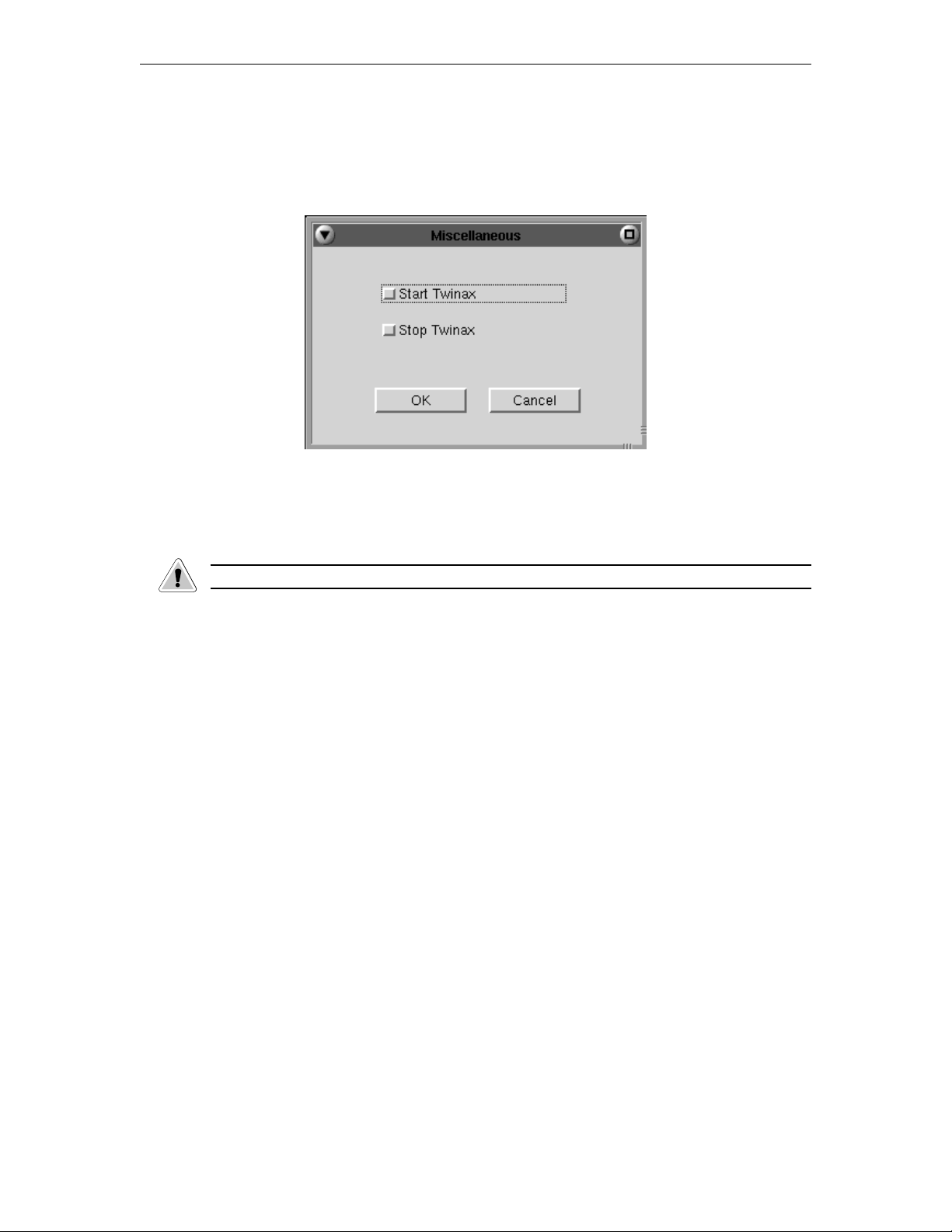
1783 Network Computing Terminal User’s Manual
Restarting the 1490 Emulator
1. Click Setup in the upper left-hand corner of the screen to open the 1490 Setup menu.
2. Click Miscellaneous. The 1490 Miscellaneous screen is shown below.
3. Click Stop Twinax.
4. Click the OK button. This stops the 1490 from responding to the controller and the
menu will be removed from the screen.
CAUTION: All data on the 1490 screen and unprinted data will be lost.
When 1490 screen data is erased the Miscellaneous panel will disappear and the cursor is
placed in the upper right corner of the screen.
5. To open the miscellaneous menu, repeat steps 1 and 2.
6. Click Start Twinax.
7. Click the OK button to restart the Twinax communications and initiate the exchange
of configuration items with the controller.
707042-0027-14
Page 77

Chapter 8
Using Telnet, TN3270, TN5250 and VT220
In this Chapter...
Telnet Terminal
TN3270
TN5250
VT220
Page 78

1783 Network Computing Terminal User’s Manual
Telnet Terminal
What is Telnet?
Telnet, using the Telnet protocol and the Internet, enables the user to gain access to
computer systems around the world.
In effect, the 1783 NCT functions as though it were a terminal connected to a remote
host. Once logged in, whatever tools are provided on the host can be used to do a variety
of things, such as:
• search databases to locate targeted information
• run specialized programs
• enter into online discussions
Telnet makes it possible for your terminal to “look like” whatever terminal the host
normally supports. An exception is certain IBM mainframe hosts running 3270
applications. To access a host as a 3270-type terminal, use the TN3270 feature, described
later in this section.
To gain permission to access a remote host, you can look up standard userids distributed
by those hosts whose administrators encourage public access, or you can set up an account
with a host and acquire a private userid and password. Some host administrators set up
access so that you can log in directly without a userid or password. Some provide special
port identifiers that need to be used.
In all cases, the host name of the computer system you wish to access is required.
Logging in to a remote host
To connect and log in to a remote host:
1. Click the button in the lower left hand corner of the screen. The application
menu will appear.
2. Click Telnet to start a Telnet session.
You will see this prompt in the window:
telnet >
Type :
open host
where host is the official name, an alias, or the Internet address of the
computer system to which you wish to connect. For example,
open {host}.{domain}.com
Note: If the host requires that a port number be specified when connecting, simply append
the port number to the host name, separated by a space.
707042-0028-2
Page 79

Chapter 8: Using Telnet, TN3270, TN5250 and VT220
Telnet will connect to the remote host. The host then will normally respond with a welcome
and will lead you through its log in process. Log in, employing one of the following
combinations:
• With the userid and password supplied by the administrator of the host
• With just a userid (some hosts do not require passwords)
• Neither, if the remote host has been set up for it.
Once connected, use the menus, commands and features of the remote host, which are
largely text-based and can vary from host to host.
Logging out of a remote host
When you are finished using the remote host, use that host’s normal log out command.
Telnet will automatically finish running.
To disconnect from the host when its log out command is not available, or if you are stuck
for any other reason, enter one of the following:
• Ctrl - ]
• the escape character displayed by the host upon logging in.
Recommended reference guides
Telnet enables many special telecommunication features to be configured, such as how
carriage returns or interrupts are processed. Such features may be needed when accessing
a non-Unix remote host. Contact your system administrator or refer to one of the
following references:
Hunt, Craig, TCP/IP Network Administration, O’Reilly & Associates, Inc.,
Cambridge, MA.
Heywood, Drew; Jerney, Janos; Johnston, Jon, et al, Connectivity: Local Area Networks,
New Riders Publishing, Carmel, IN.
707042-002 8-3
Page 80
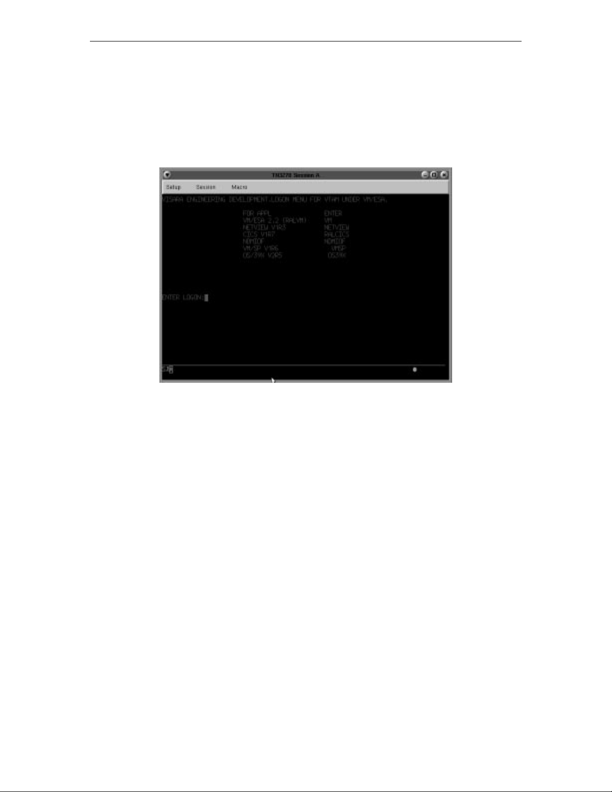
1783 Network Computing Terminal User’s Manual
TN3270
What is TN3270?
Like Telnet, TN3270 enables access to programs running on remote hosts. Unlike Telnet,
TN3270 provides the means to access 3270 programs running on IBM mainframes.
TN3270 enables the 1783 NCT to function as though it were a 3279 mod 2, mod 3, mod
4, or mod 5 terminal. Unlike Telnet, TN3270 can manipulate the entire screen image,
fields and function keys, in a way identical to a 3270 terminal. TN3270 provides the
following standard features:
• Window Menus – The window menus offer simplicity and ease of use for all setup
functions.
• Color Display – The color monitor is programmable in seven colors.
• Switchable Screen Formats – TN3270 supports four (4) screen sizes that can be
selected from setup menus. The server to which the TN3270 client attaches must be
configured to support the screen size used. Check with your system administrator.
• Mono/DualCase Mode – Allows characters to be displayed as all uppercase
characters or as upper- and lowercase characters.
• Mark Unprotected Field Indicator – The 1480 CUT Emulator can be requested
to mark unprotected fields with a special character.
• Row/Column Indicator – Displays the current cursor location on the operator
status row.
• Numeric Lock – Allows a field to be defined to accept only numeric characters and
the Period, Minus, and Dup keys. The comma may be substituted for the period on
some international keyboards.
• Multiple Sessions – A maximum of 10 sessions can be accessed with this emulator.
707042-0028-4
Page 81
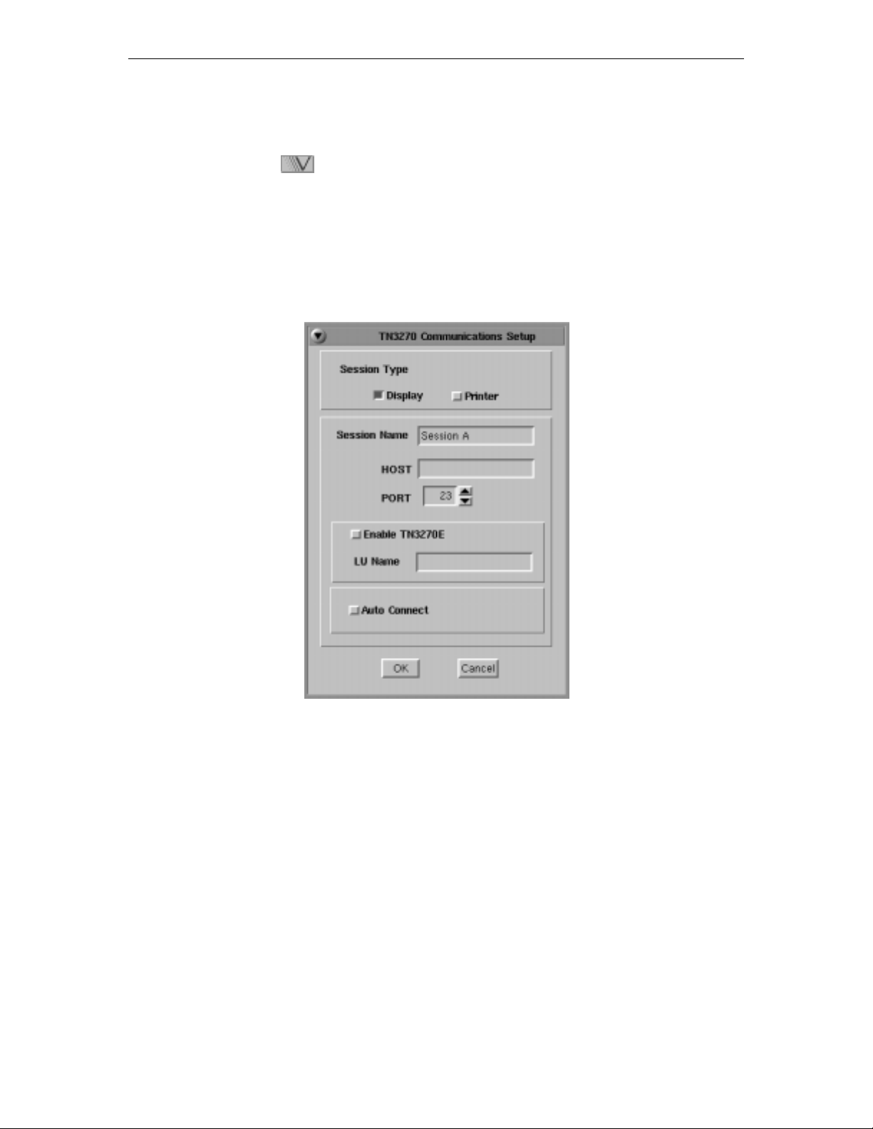
Chapter 8: Using Telnet, TN3270, TN5250 and VT220
Setting up a remote host as a 3270 terminal
To setup a remote host:
1. Click the button in the lower left-hand corner of the screen. The application
menu will appear.
2. Click TN3270. The main TN3270 screen will appear with two menu options, Setup
and Session.
3. Click Setup.
4. Click Communications from the Setup menu. This screen will appear:
• Session Type – Select Display to configure a TN3270 Display session. Select
Printer to configure a TN3287 Printer session.
• Session Name – Enter the name to be displayed in the window title.
• Host – Enter the Internet address of the TN3270 server to which you wish to connect,
for example, 255.255.XXX.XXX.
• Port – If the host requires that a port number (other than port 23) be specified when
connecting, select the port number using the up and down arrows or by typing the port
in directly.
• Enable TN3270E – Select to enable TN3270E support.
• LU Name – Enter LU name string (optional, for TN3270E).
• Auto Connect – Select to auto connect at program start and to reconnect automatically
if disconnected by the server.
Click OK to save changes and close Communications Setup, or Cancel to close and
discard any changes.
707042-002 8-5
Page 82

1783 Network Computing Terminal User’s Manual
Connecting to a TN3270 session
TN3270 will connect to the remote IBM mainframe host. The host then will normally
respond with a welcome and will lead you through its log in process. Log in, employing
one of the following combinations:
• With the userid and password supplied by the administrator of the host
• With just a userid (some hosts do not require passwords)
• Neither, if the remote host has been set up for it.
To connect to a TN3270 remote host from the main TN3270 screen:
1. Click Session to open the TN3270 Session menu.
2. Click Connect.
Once connected, use the menus, commands and features of the remote host to access and
run 3270 applications.
Logging out of a remote host
1. When you have finished using the remote host, use the host’s normal log out command.
2. To disconnect from the host, select Disconnect from the Session menu.
707042-0028-6
Page 83
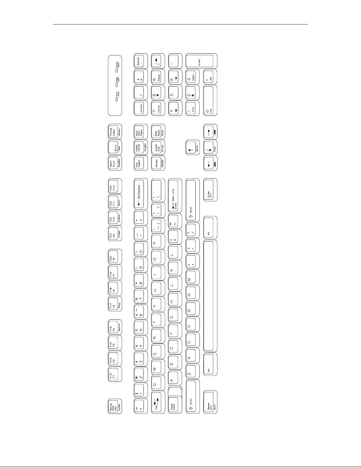
Chapter 8: Using Telnet, TN3270, TN5250 and VT220
TN3270
104-key Keyboard Layout
707042-002 8-7
Page 84
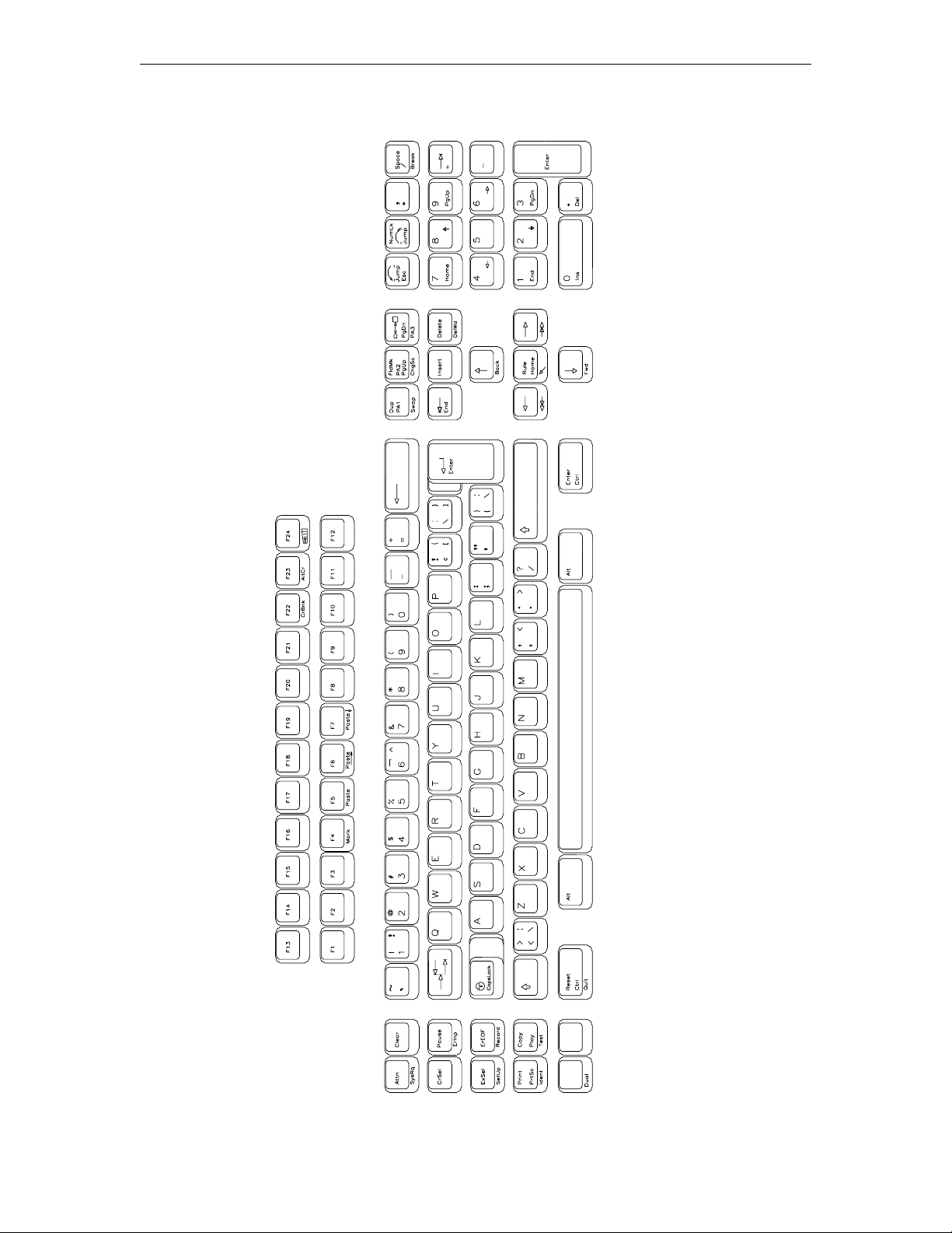
1783 Network Computing Terminal User’s Manual
TN3270
122-key Keyboard Layout
707042-0028-8
Page 85
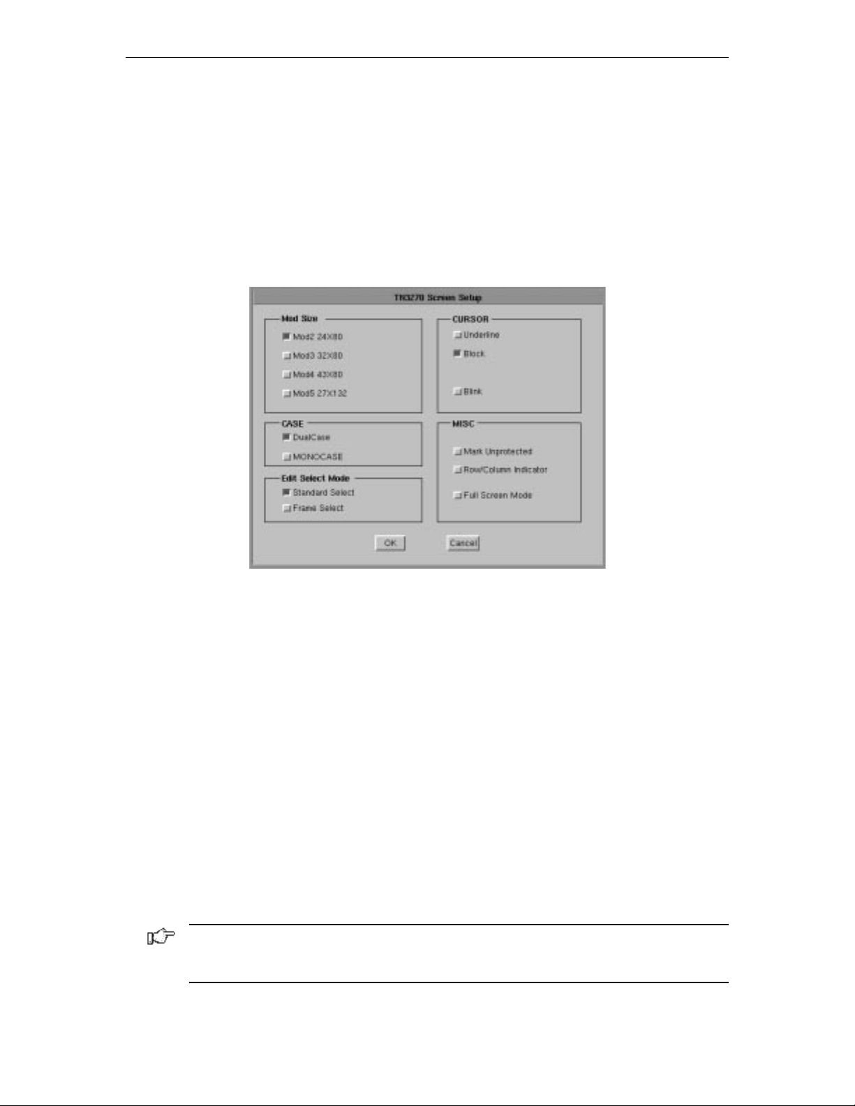
Chapter 8: Using Telnet, TN3270, TN5250 and VT220
Configuring TN3270 for an application
TN3270 can be configured for a particular application by selecting Screen, Keyboard
or Color from the Setup menu.
Screen setup
From the main TN3270 application screen:
1. Click Setup to open the TN3270 Setup menu.
2. Click Screen.
• Mod Size – Select the mod required by the design of the application program.
Applications are designed to use one of the above mods, based on the number of rows
per screen and characters per row, respectively. The default is Mod 2.
• Case – Select DualCase for upper and lower case characters. Select MONOCASE
for all characters displayed as upper case letters.
• Edit Select Mode – Choose either Standard Select or Frame Select. Standard
select performs an end-of-line wrap function when selecting text. Frame Select is
used to a specific block of text without automatically performing an end-of-line wrap
function.
• Cursor – Choose either an underline cursor or a block cursor. Select Blink for a
blinking cursor.
• Mark Unprotected – Select to display a special symbol in each unprotected field on
the screen. This enables you to recognize locations where keystrokes can be entered.
• Row/Column Indicator – Select to display the current cursor location on the operator
status row. Note that the location is determined by the application program on the host system.
• Full Screen Mode – Select to open the TN3270 application in Full Screen Mode.
TN3270 must be closed and reopened for this setting to become effective.
Note: To access the taskbar or minimized applications on the taskbar while Full Screen
Mode is in effect, hold down the Ctrl and Alt keys while pressing the tab key. Press the tab
key repeatedly until the name of the application you wish to bring to the front is displayed.
Click OK to save changes and close Screen Setup, or Cancel to close and discard
any changes.
707042-002 8-9
Page 86
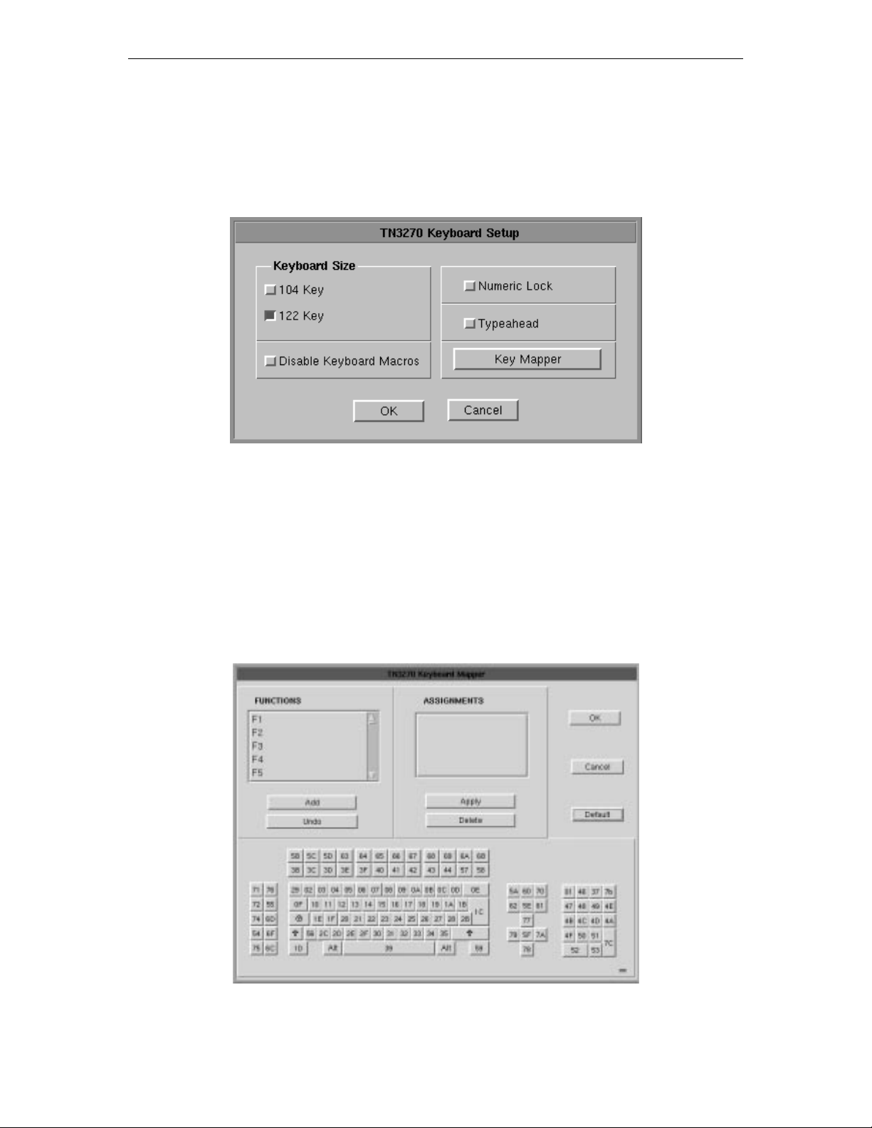
1783 Network Computing Terminal User’s Manual
Keyboard setup
From the main TN3270 application screen:
1. Click Setup to open the TN3270 Setup menu.
2. Click Keyboard.
• Keyboard Size – Select either the 104 or 122-key keyboard.
• Disable Keyboard Macros – Prevents the user from assigning user-defined macro
functions to keys.
• Numeric lock – If supported by the TN3270 server, will allow numeric keys only for
numeric fields.
• Typeahead – Enable the Typeahead feature.
• Key Mapper – The key assignment (mapping) may be verified or changed as
necessary for use in TN3270 applications.
Keyboard Mapper
707042-0028-10
Page 87
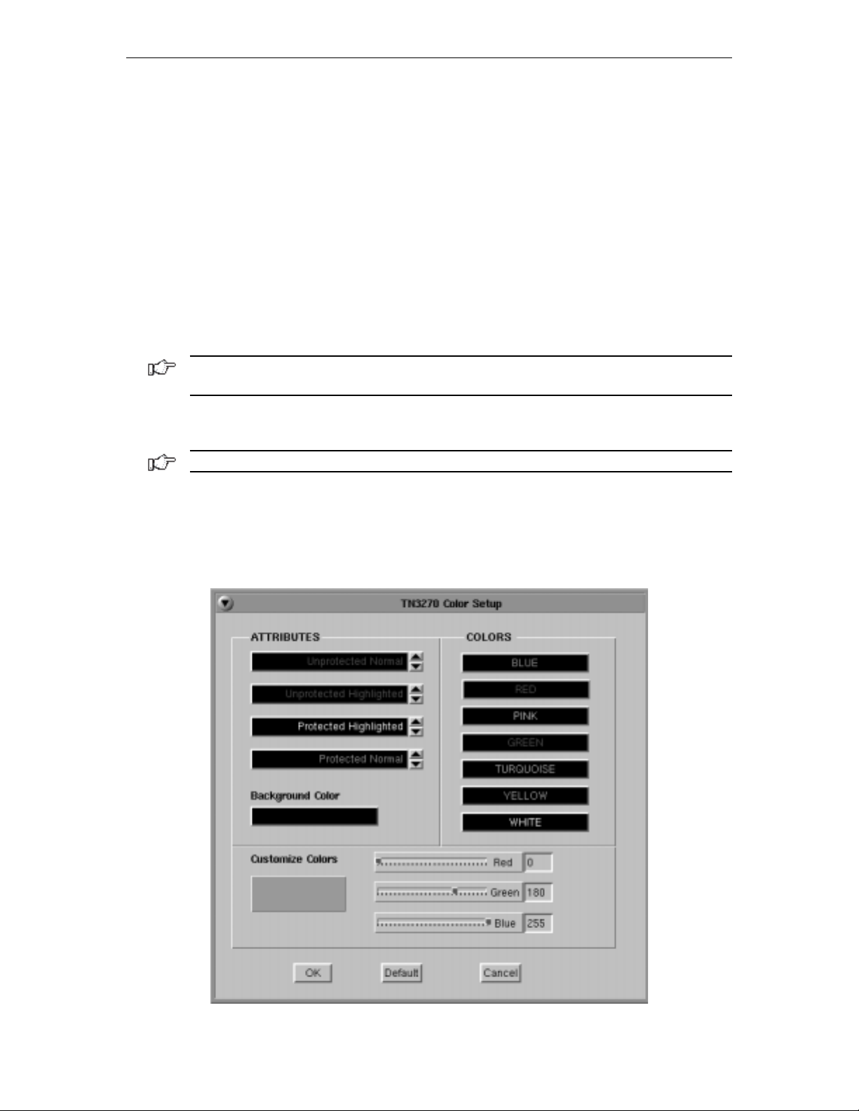
Chapter 8: Using Telnet, TN3270, TN5250 and VT220
To determine which 1783 key is currently assigned to the key, click the appropriate key in
the Functions box and the assigned value will be displayed in the Assignments box.
Alternatively, on the keyboard layout, using the mouse click on the key to which the value
needs to be displayed, the key will be displayed in the Functions box and the assigned
value in the Assignments box.
To change the key assignment:
1.Using the mouse, click on the key that needs to be changed on the keyboard layout
or alternatively, choose the function from the Functions box.
2. Click Add below the Functions box.
3. Assign the new assignment required for the key selected. If a key combination is
desired, click either the Shift, Control, or Shift + Control buttons.
4. Click Apply when satisfied with selection or click Undo to reassign.
Note: A function can be applied to multiple 1783 keys. Assigning a function to a key does
not unassign it from a previous definition.
5. Click OK to save changes and Exit, or Cancel to discard changes and exit. To
return the key assignments to their default state, click Default.
Note: TN3270 application must be closed and restarted for changes to become effective.
Color Setup
From the main TN3270 application screen:
1. Click Setup to open the TN3270 Setup menu.
2. Click Colors.
707042-002 8-11
Page 88
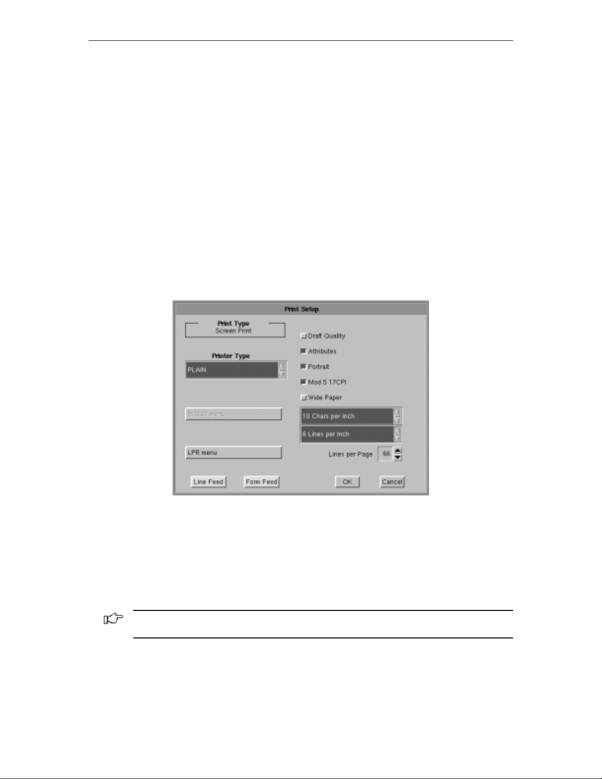
1783 Network Computing Terminal User’s Manual
• Attributes – Use the arrows to select colors from the Colors list on the right. Select
for protected, unprotected, normal and highlighted fields.
• Customize Colors – Select a color from the colors list. Use any or all of the three
slider bars to adjust the selected color.
• Background color – Select the Background Color bar, then apply any or all of the
three slider bars until the desired color shows in the Background Color box.
Click OK to save changes and close Color Setup, or Cancel to close and discard
any changes.
Print setup
To access the Print Setup screen (shown below) from the main TN3270 screen:
1. Click Setup to open the TN3270 Setup menu.
2. Click Printer.
Print type
• Screen print – Prints the entire contents of the application window
• Printer Type – Specifies the printer driver to use when printing. Options are:
– Plain
– HP Laserjet
– Epson Inkjet
– Proprinter
– Postscript
Note: Printing options found on this configuration panel may vary depending on the
printer type selected.
• Draft – Prints draft quality when selected. Otherwise printing is letter quality.
• Attributes – If selected, prints intensified characters as bold and underlined
when required.
• Portrait – If enabled, prints in Portrait mode. If disabled, prints in Landscape mode.
707042-0028-12
Page 89
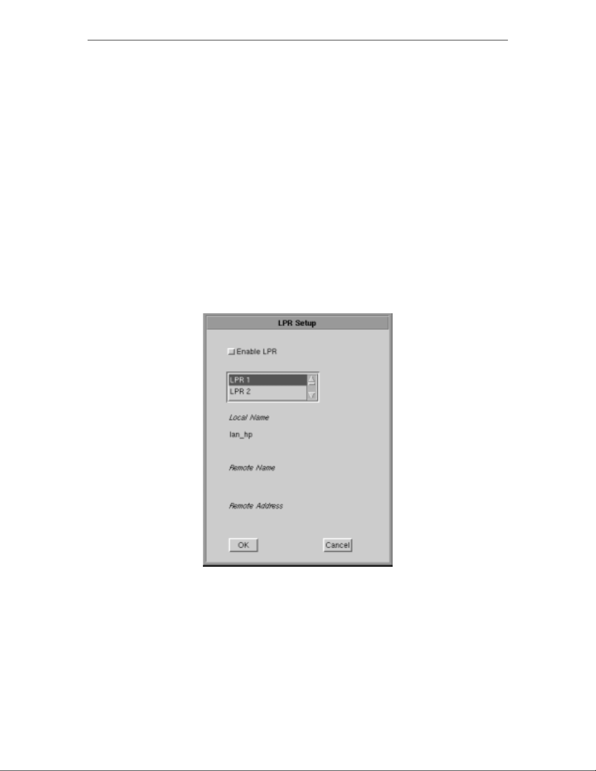
Chapter 8: Using Telnet, TN3270, TN5250 and VT220
• Mod 5 17 CPI – If selected, printing automatically changes to 17 CPI (characters per
inch) if the application screen is Mod 5.
• Wide Paper – If enabled, allows printing of more than 80 characters per line. This
setting is generally used when Proprinter is selected as the Printer Type.
• CPI Selection – Specifies the number of Characters Per Inch to print. Options are
10, 10.5, 12, and 17 CPI.
• LPI Selection – Specifies the number of Lines Per Inch to print. Options are 3, 4, 6,
8, and 8.4 LPI.
• Lines per page – Specifies the number of Lines per Page to print. Selectable range
is 0-255.
• Line Feed – Sends an immediate Line Feed to the selected printer.
• Form Feed – Sends an immediate Form Feed to the selected printer
• LPR Menu – Displays the LPR configuration menu. The LPR menu button is gray
when LPR is disabled and green when enabled.
LPR menu
To configure LPR, select the LPR Menu button. The LPR Setup panel is shown below:
• Enable LPR – Select to enable LPR printing.
• LPR scroll window – Used to select an LPR printer. A blue background indicates
the printer is selected.
• Local Name – User-defined name of the printer.
• Remote Name – Queue name that print jobs are sent to from an LPR-enabled device.
• Remote Address – IP address of the selected printer.
Click OK to save changes and exit, or Cancel to exit and discard any changes.
707042-002 8-13
Page 90
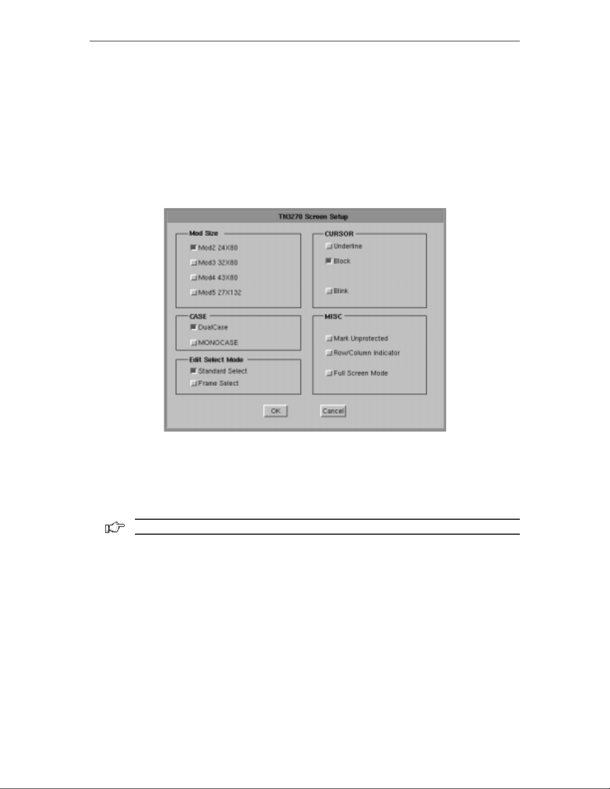
1783 Network Computing Terminal User’s Manual
Copy/Paste Between TN3270 Sessions
Use the Copy/Paste feature to copy data between sessions or applications. This feature
allows you to quickly mark, copy and paste data between fields in different sessions.
The mark field is the area which is highlighted as the data source. The data to be pasted
must be within a displayed field. Data cannot be marked for pasting if it is in a
nondisplayable field. Data may be pasted from protected as well as unprotected fields.
You must select the mark field before you select the paste field.
Mark/Copy Field
To select the mark field, position the cursor with the mouse, then press and hold the Shift
key while dragging the cursor over the source field you wish to copy. The mark field is
displayed in reverse video to indicate that it has been selected. The choice between
“Standard” (default) and “Frame” in the Screen Setup, Edit Select Mode (as shown above),
will either highlight text lines or will select complete text blocks.
Note: Data can be marked and copied from protected as well as unprotected fields.
After selecting a field, press Alt C to copy selection into the clipboard where it may be
used to paste to other sessions.
Data may also be copied from other applications into a TN3270 session as long as the
applications support “text only” copy.
707042-0028-14
Page 91
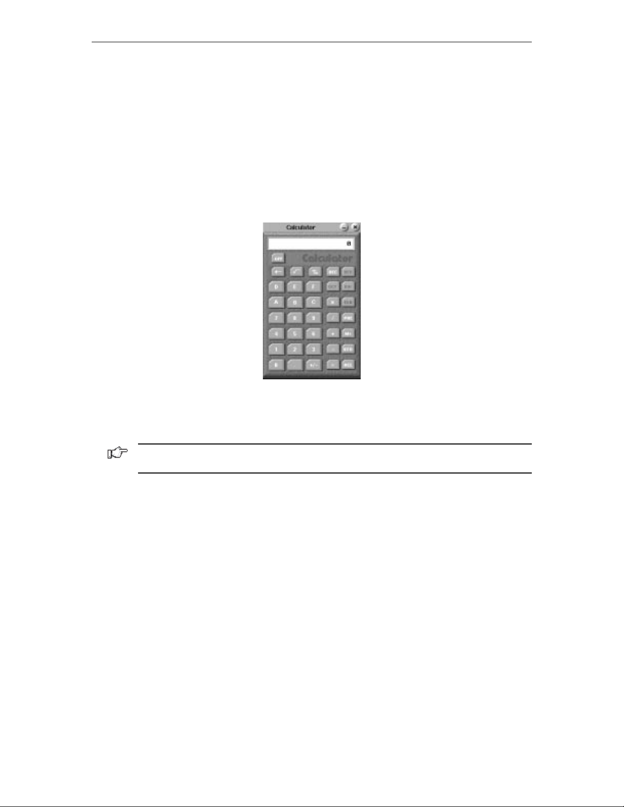
Chapter 8: Using Telnet, TN3270, TN5250 and VT220
Paste Field
The paste field is the field that receives the data from the mark field. The paste field must
be an unprotected field. Standard data truncation rules apply when the paste and mark
fields are of different lengths. If the paste field is longer than the mark field, data is
replaced in the paste field only up to the length of the mark field. If the paste field is
shorter than the mark field, data is truncated up to the length of the paste field. The data
that has been pasted is temporary until you press an Aid key (Enter or F key). To paste the
data you select using the Copy/Paste, position the cursor with the mouse and press Alt V.
Copy/Paste From Calculator to TN3270 Session
All entries on the calculator are automatically stored into the clipboard, therefore, there is
no need to copy the field. Perform the calculation you require, switch back to the session
and place the cursor where the data is required. Press Alt V to paste the calculated field.
Note: Every entry on the calculator overrides the buffer in the clipboard. Only the last
entry/calculation is available.
Recommended reference guide
TN3270 allows you to configure special features and to temporarily suspend/resume a
host session. You may need to configure new 3278 models as support for them becomes
available, or you may need more information on controlling a host session. Contact your
system administrator or refer to the following reference:
“Yale ASCII Terminal Communication,” System II Program Description/Operator’s Manual
(IBM SB30-1911).
707042-002 8-15
Page 92
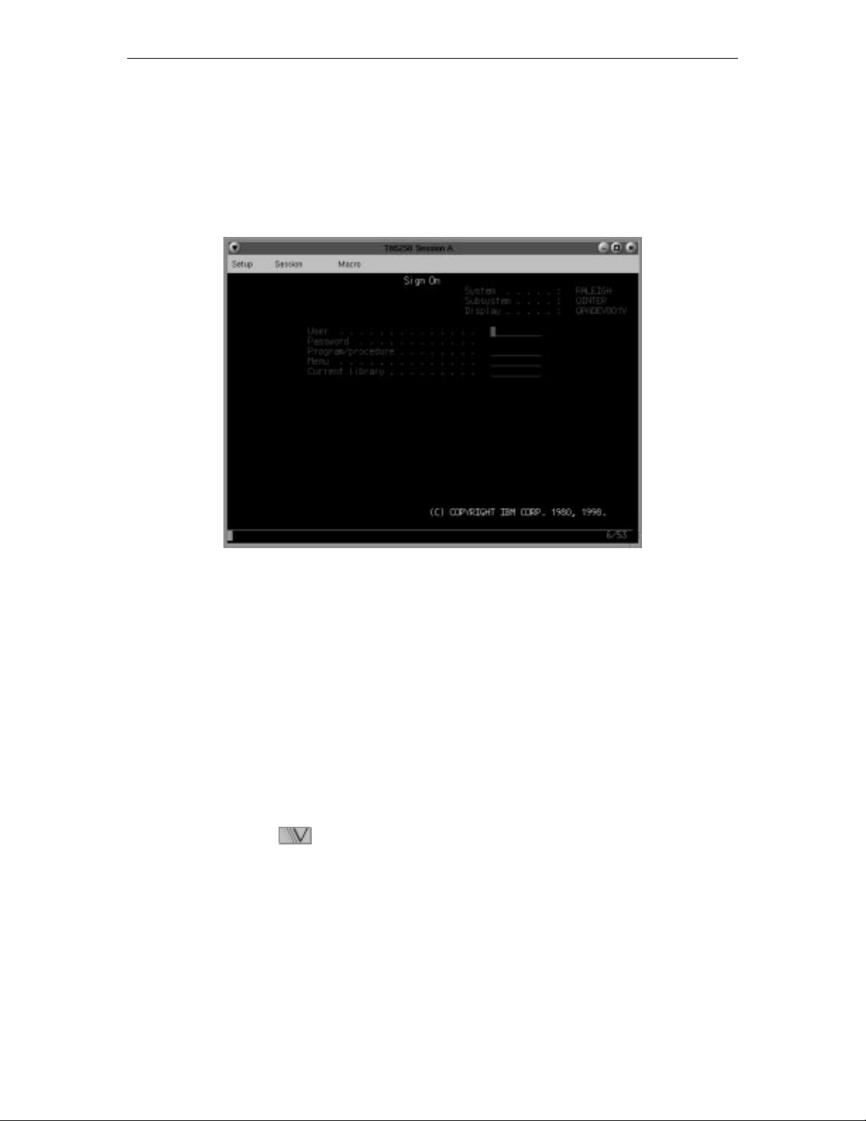
1783 Network Computing Terminal User’s Manual
TN5250
What is TN5250?
Like Telnet, TN5250 enables the user to access programs running on remote hosts. TN5250
provides the means to access 5250 programs running on IBM midframes.
TN5250 can manipulate the entire screen image, fields and function keys, in a way identical
to a 5250 terminal. TN5250 provides the following standard features:
• Window Menus – The window menus offer simplicity and ease of use for all
setup functions.
• Color Display – The color monitor is programmable in seven colors.
• Row/Column Indicator – Displays the current cursor location on the operator
status row.
• Multiple Sessions – A maximum of 10 sessions can be accessed with this emulator.
Setting up a remote host as a 5250 terminal
To setup a remote host:
1. Click the button in the lower left-hand corner of the screen. The application
menu will appear.
2. Click TN5250. The main TN5250 screen will appear with two menu options, Setup
and Session.
3. Click Setup.
707042-0028-16
Page 93
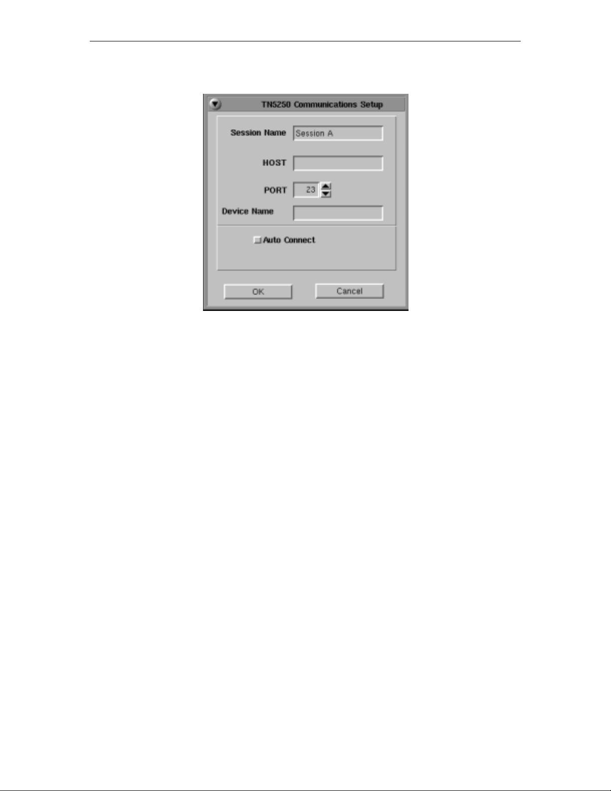
Chapter 8: Using Telnet, TN3270, TN5250 and VT220
4. Click Communications from the Setup menu. This screen will appear:
• Session Name – Enter the name to be displayed in the window title.
• Host – Enter the Internet address of the TN5250 server to which you wish to connect,
for example, 255.255.XXX.XXX.
• Port – If the host requires that a port number (other than port 23) be specified when
connecting, select the port number using the up and down arrows or by typing the port
in directly.
• Device Name – Enter a name for the device or LU name.
• Auto Connect – Select to auto connect at program start and to reconnect automatically
if disconnected by the server.
Click OK to save changes and close Communications Setup, or Cancel to close and
discard any changes.
Connecting to a TN5250 session
TN5250 will connect to the remote host. The host then will normally respond with a
welcome and will lead you through its log in process. Log in, employing one of the
following combinations:
• With the userid and password supplied by the administrator of the host
• With just a userid (some hosts do not require passwords)
• Neither, if the remote host has been set up for it.
To connect to a TN5250 remote host from the main TN5250 screen:
1. Click Session to open the TN5250 Session menu.
2. Click Connect.
Once connected, use the menus, commands and features of the remote host to access and
run 5250 applications.
707042-002 8-17
Page 94
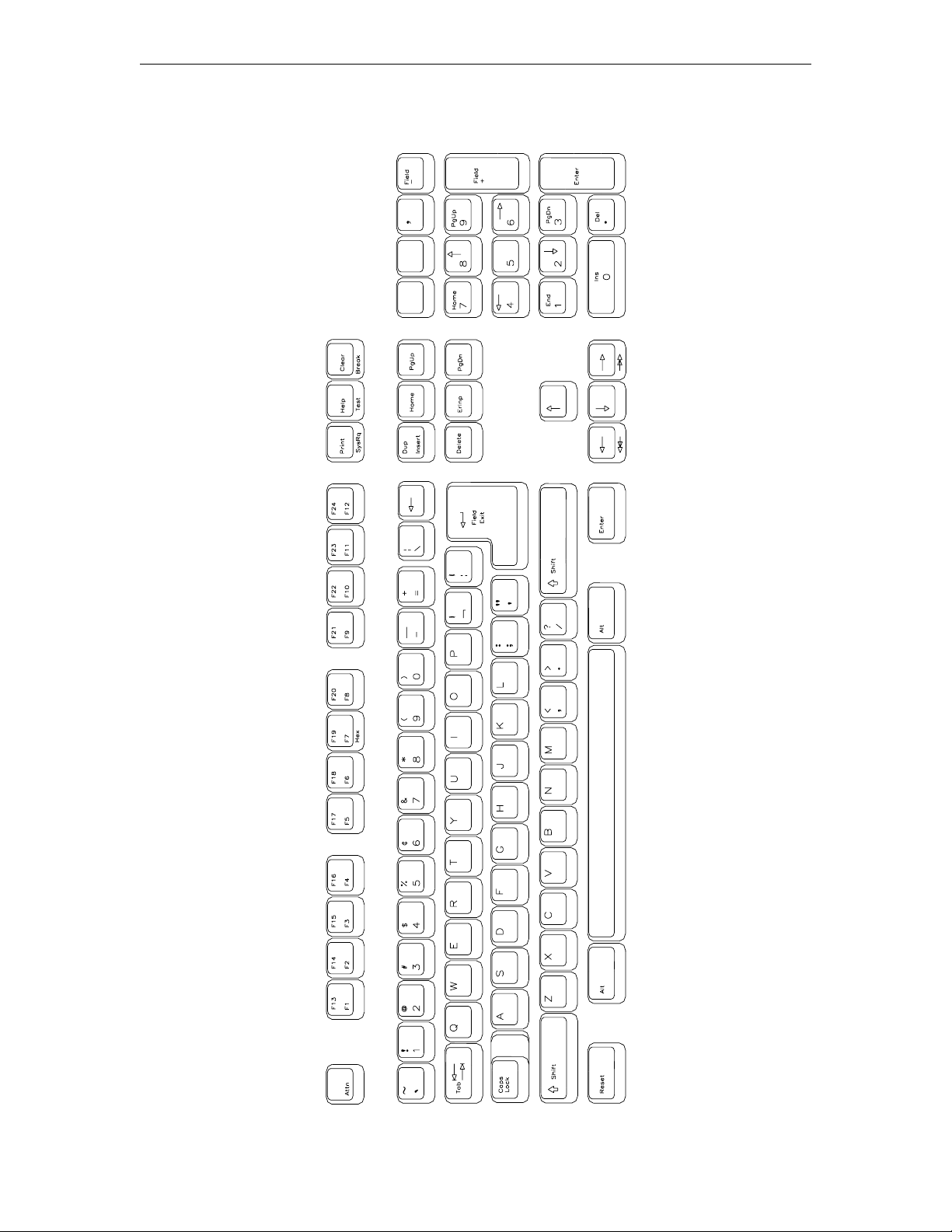
1783 Network Computing Terminal User’s Manual
TN5250
104-key Keyboard Layout
707042-0028-18
Page 95
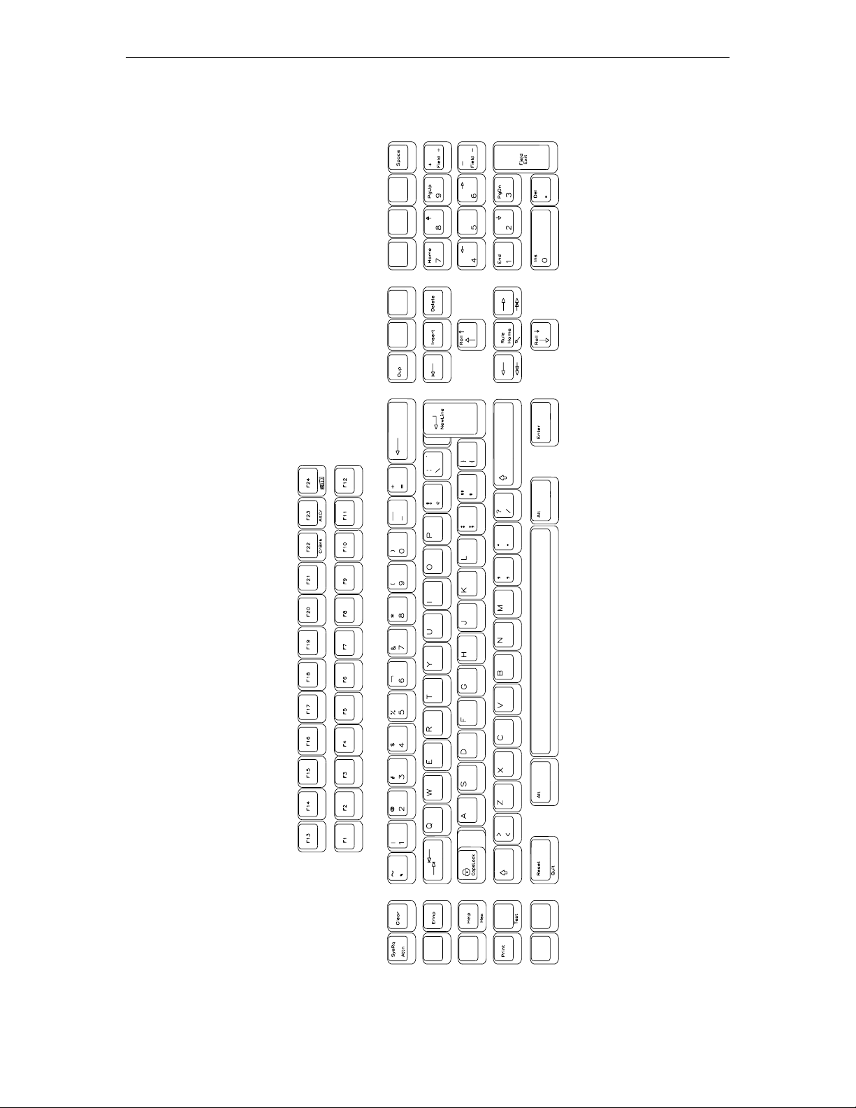
Chapter 8: Using Telnet, TN3270, TN5250 and VT220
TN5250
122-key Keyboard Layout
707042-002 8-19
Page 96
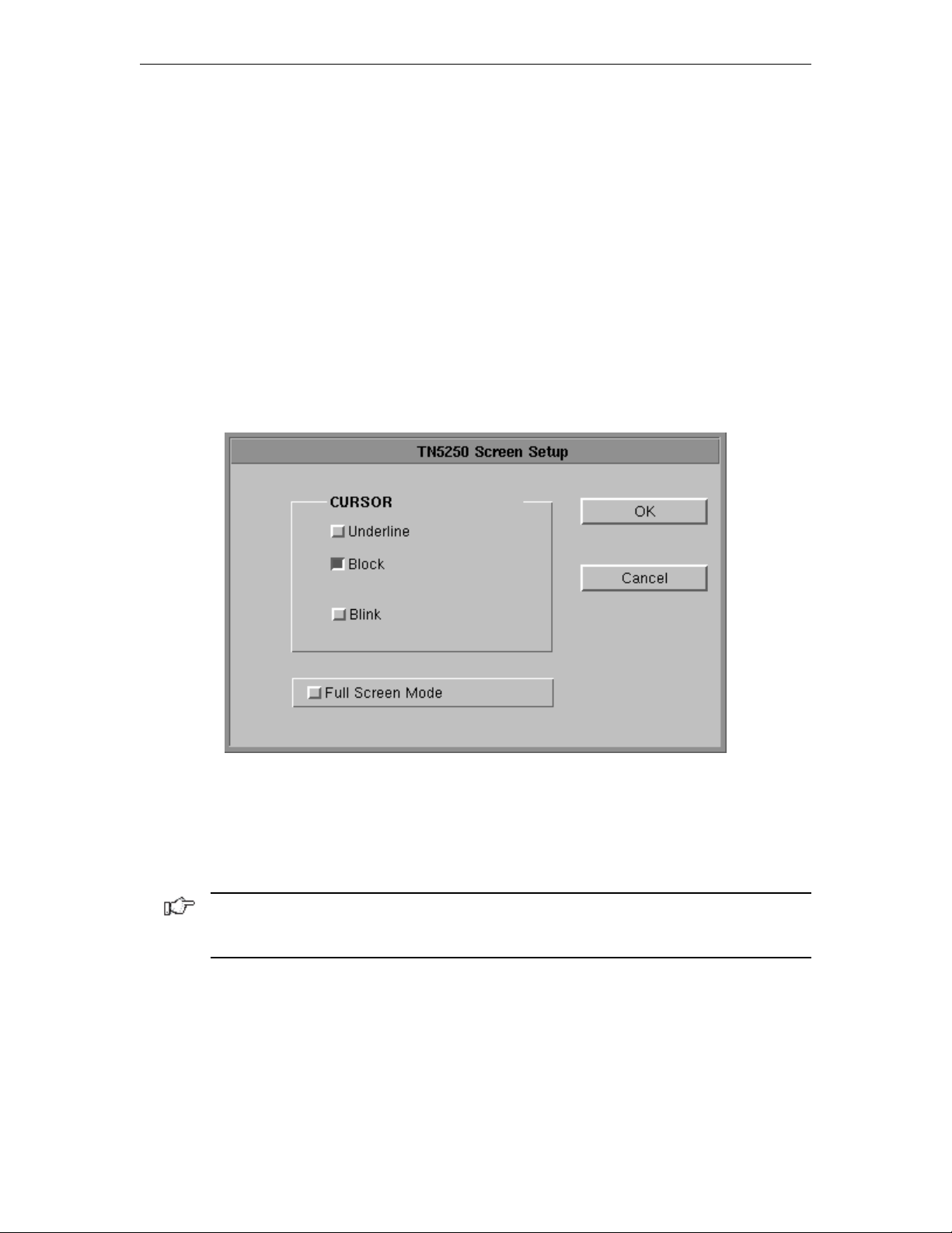
1783 Network Computing Terminal User’s Manual
Logging out of a remote host
1. When you have finished using the remote host, use the host’s normal log out command.
2. To disconnect from the host, select Disconnect from the Session menu.
Configuring TN5250 for an application
TN5250 can be configured for a particular application by selecting Screen, Keyboard
or Color from the Setup menu.
Screen setup
From the main TN5250 application screen:
1. Click Setup to open the TN5250 Setup menu.
2. Click Screen.
• Cursor – Choose either an underline cursor or a block cursor. Select Blink for a
blinking cursor.
• Full Screen Mode – Select to open the TN5250 application in Full Screen Mode.
TN5250 must be closed and reopened for this setting to become effective.
Note: To access the taskbar or minimized applications on the taskbar while Full Screen
Mode is in effect, hold down the Ctrl and Alt keys while pressing the tab key. Press the tab
key repeatedly until the name of the application you wish to bring to the front is displayed.
Click OK to save changes and close Screen Setup, or Cancel to close and ignore
any changes.
707042-0028-20
Page 97
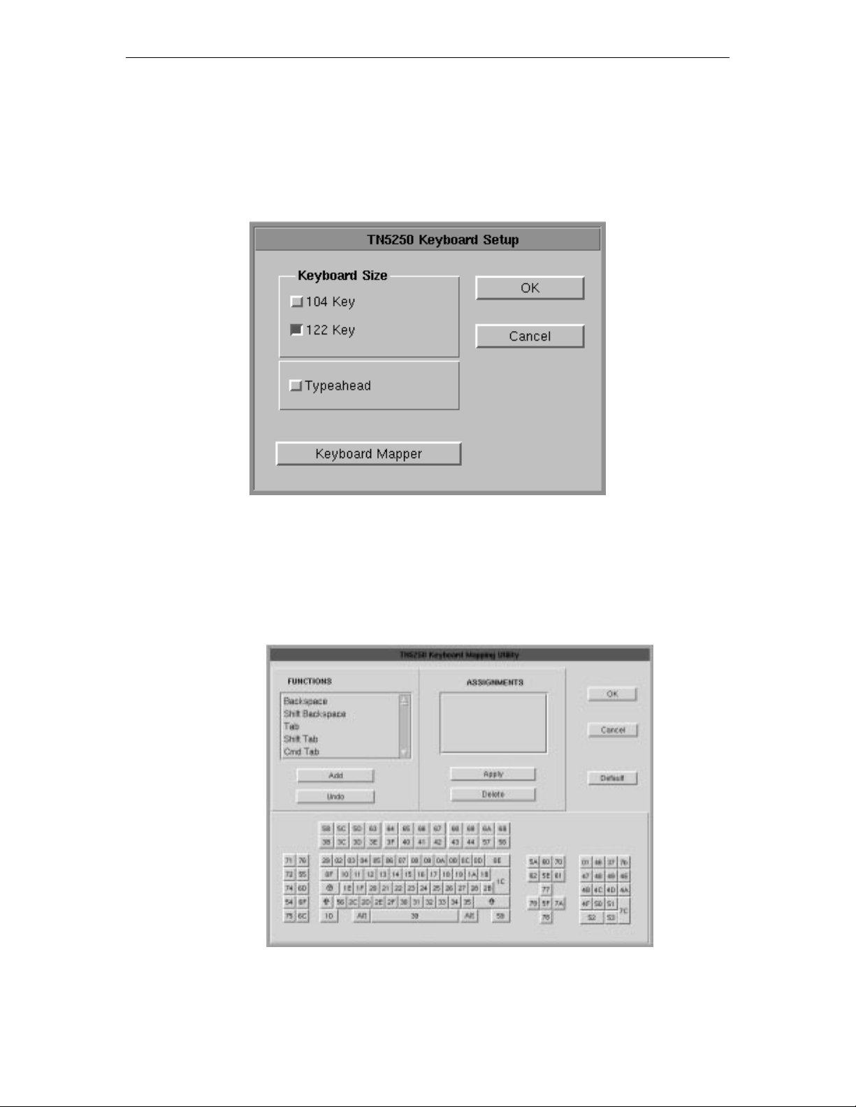
Chapter 8: Using Telnet, TN3270, TN5250 and VT220
Keyboard setup
From the main TN5250 application screen:
1. Click Setup to open the TN5250 Setup menu.
2. Click Keyboard.
• Keyboard Size – Select either 104 or 122-key keyboard.
• Typeahead – Enable the Typeahead feature.
• Keyboard Mapper – The key assignment (mapping) may be verified or changed
as necessary for use in TN5250 applications.
Keyboard Mapper
To determine which 1783 key is currently assigned to the key, click the appropriate key in
the Functions box and the assigned value will be displayed in the Assignments box.
707042-002 8-21
Page 98
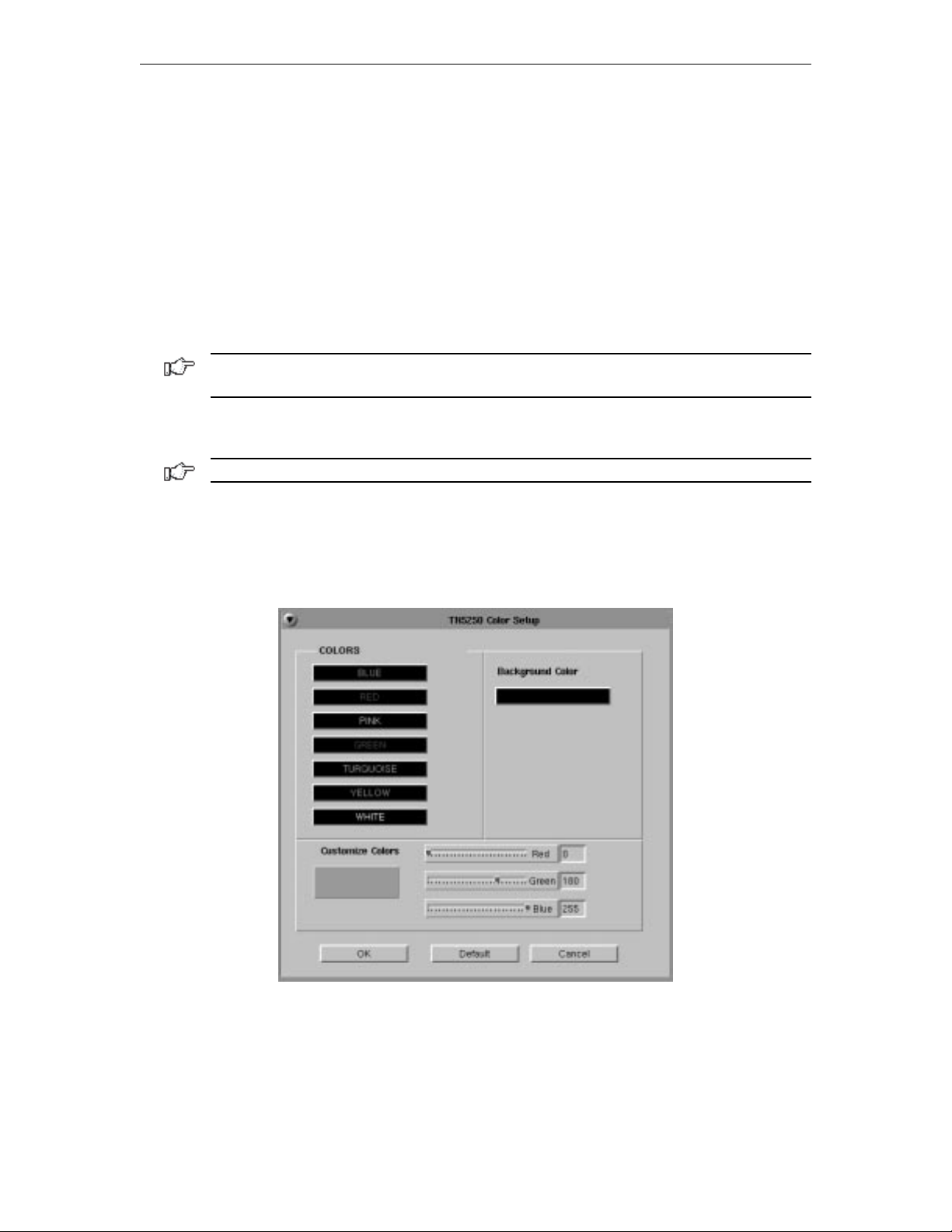
1783 Network Computing Terminal User’s Manual
Alternatively, on the keyboard layout, using the mouse click on the key to which the value
needs to be displayed, the key will be displayed in the Functions box and the assigned
value in the Assignments box.
To change the key assignment:
1.Using the mouse, click on the key that needs to be changed on the keyboard layout
or alternatively, choose the function from the Functions box.
2. Click Add below the Functions box.
3. Assign the new assignment required for the key selected. If a key combination is
desired, click either the Shift, Control, or Shift + Control buttons.
4. Click Apply when satisfied with selection or click Undo to reassign.
Note: A function can be applied to multiple 1783 keys. Assigning a function to a key does
not unassign it from a previous definition.
5. Click OK to save changes and Exit, or Cancel to discard changes and exit. To
return the key assignments to their default state, click Default.
Note: TN5250 application must be closed and restarted for changes to become effective.
Color Setup
From the main TN5250 application screen:
1. Click Setup to open the TN5250 Setup screen.
2. Click Colors.
3. Select a color from the Colors list or Background Color. Use any or all of the three
slider bars to adjust the selected color.
Click OK to save changes and close Color Setup, or Cancel to close and discard
any changes.
707042-0028-22
Page 99
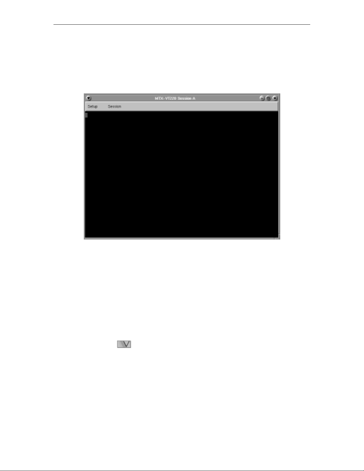
VT220
What is VT220?
Like Telnet, VT220 enables you to access programs running on remote hosts.
Chapter 8: Using Telnet, TN3270, TN5250 and VT220
Welcome to HAL, a DEC 3000 Model 300 (AXP) running VMS version V6.1
Username: _
VT220 enables the 1783 NCT to function as though it were a standard VT220 display.
VT220 provides the following standard features:
• Window Menus – The window menus offer simplicity and ease of use for all setup
functions.
• Color Display – The color monitor is programmable.
• Multiple Sessions – A maximum of 10 sessions can be accessed with this emulator.
Setting up VT220
To setup a remote host:
1. Click the button in the lower left-hand corner of the screen. The application
menu will appear.
2. Click VT220. The main VT220 screen will open with two menu options, Setup and
Session.
3. Click Setup.
707042-002 8-23
Page 100
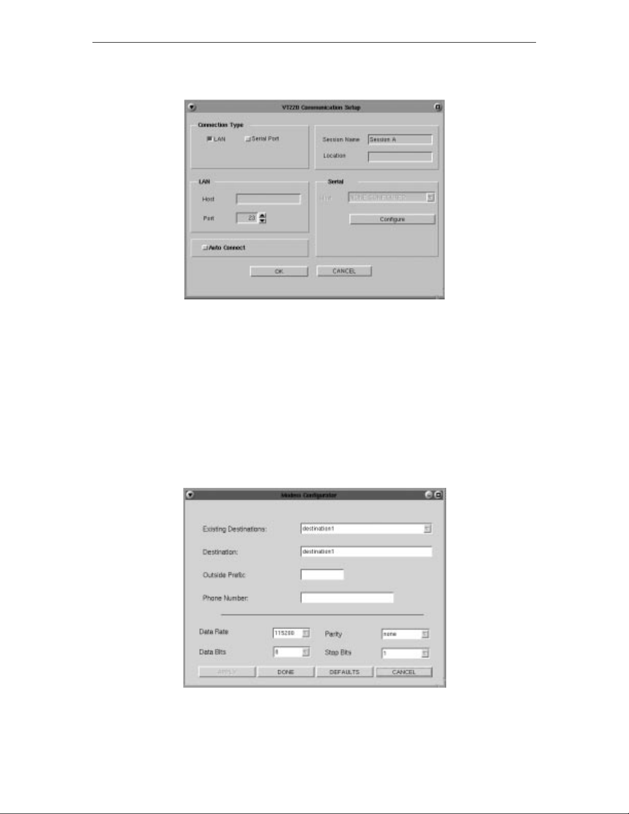
1783 Network Computing Terminal User’s Manual
4. Click Communications from the Setup menu. This screen will appear:
• Connection Type – Select either a LAN or Serial connection.
• LAN
– Host – Enter the Internet address of the VT220 server to which you wish to
connect, for example, 255.255.XXX.XXX.
– Port – If the host requires that a port number (other than port 23) be specified
when connecting, select the port number using the up and down arrows or by
typing the port in directly.
• Auto Connect – Select to auto connect at program start-up.
• Session Name – Enter the name to be displayed in the window title.
• Serial – Select the Baud rate, parity, data bits and stop bits for the serial connection.
• Configure – Select to display the Serial Communications Configuration Panel.
Click OK to save changes and close Communications Setup, or Cancel to close and
discard any changes.
707042-0028-24
 Loading...