

Page 1

SCON-25L/28L/3074 Console Concentrator
1174-25S Communications Server
Hardware Reference Manual
P/N 707028-007
Page 2
ELUDEHCSNOISIVER/EUSSI
Comments Rev. No. Date
Initial Release 707028-001 9/17/99
Visara Update 707028-002 3/26/01
SCON-25L Addition 707028-003 9/12/02
Update/28L Addition 707028-004 9/15/04
Update 707028-005 8/18/05
SCON-3074 Addition 707028-006 5/12/06
Update 707028-007 9/25/07
ii 707028-007
Page 3

Read This First
This is the Communications Server Hardware Reference Manual. For
information on the LINCS Operating System, please visit our website,
www.visara.com.
1. From your Internet browser type http://www.visara.com
2. Select Service and Support
3. Select Manuals
4. Select 1174 LINCS Manual Online
•
SCON-25L/28L/3074/1174-25S Hardware Reference Manual
•
SCON-20L/22L/25L/28L Configuration Manual
•
SCON-3074 Configuration Manual
•
SCON-20L/22L/25L/28L/3074 Planning and Installation Manual
•
LINCS Features
•
LINCS Problem Determination
•
LINCS Configuration
•
LINCS Central Control
707028-007 iii
Page 4

Product Safety
The 25L/28L/25S/3074 complies with relevant product safety standards, such as the UL
and CSA, and TUV-GS Rules and Regulations.
FCC and CDC Regulatory Statements
This equipment has been tested and found to comply with the limits for a Class A computing
device, pursuant to Part 15 of the FCC rules. These limits are designed to provide reasonable
protection against harmful interference in a commercial installation. This equipment generates,
uses, and can radiate radio frequency energy, and, if not installed and used in accordance with
the instructions, may cause harmful interference to radio communications. However, there is
no guarantee that interference will not occur in a particular installation. If this equipment
does cause harmful interference to radio or television reception, which can be determined by
turning the equipment off and on, the user is encouraged to try to correct the interference by
using one or more of the following measures:
• Reorient or relocate the receiving antenna.
• Increase the separation between the equipment and the receiver.
• Connect the equipment into an outlet on a circuit different from that to which the receiver
is connected.
• Consult the dealer or an experienced radio/TV technician for help.
This equipment has been certified to comply with the limits for a Class A computing device,
pursuant to FCC rules. In order to maintain compliance with FCC regulations, shielded cable
must be used with this equipment. Operating with unapproved equipment or unshielded cables
is likely to result in interference to radio and TV reception. The user is cautioned that changes
and modifications made to the equipment without the approval of the manufacturer could
void the user’s authority to operate this equipment. The user may find the following booklet
prepared by the Federal Communications Commission helpful:
How to Identify and Resolve Radio-TV Interference Problems.
This booklet is available from the U.S. Government Printing Office, Washington DC 20402,
Stock No. 004-000-00345-4.
This digital apparatus does not exceed the Class A limits for radio noise emissions from
digital apparatus set out in the Radio Interference Regulations of the Canadian Department of
Communications.
Le présent appereil numérique n’émet pas de bruits radioélectriques dépassant les limites
applicables aux appareils numériques de la classe A prescrites dans le Règlement sur le
brouillage radioélectrique édicté par le ministère des Communications du Canada.
WARNING
Due to electrical hazard, do not remove the system cover. Only qualified service personnel
may remove the system cover for service or installation of circuit cards.
iv 707028-007
Page 5

Table of Contents
Page
Read This First ........................................................................................................... iii
Product Safety .................................................................................................. iv
FCC and CDC Regulatory Statements ............................................................. iv
Chapter 1. Introduction ............................................................................................ 1-1
SCON-25L General Description ................................................................... 1-1
SCON-28L General Description ................................................................... 1-1
SCON-3074 General Description .................................................................. 1-1
1174-25S General Description ...................................................................... 1-1
TN3270E Server........................................................................................ 1-2
Communications Concentrator .................................................................. 1-2
Coax Terminal Server ................................................................................ 1-2
LAN Printer Support ................................................................................. 1-2
Additional LAN Device Support............................................................... 1-2
IP Channel Bridge ..................................................................................... 1-2
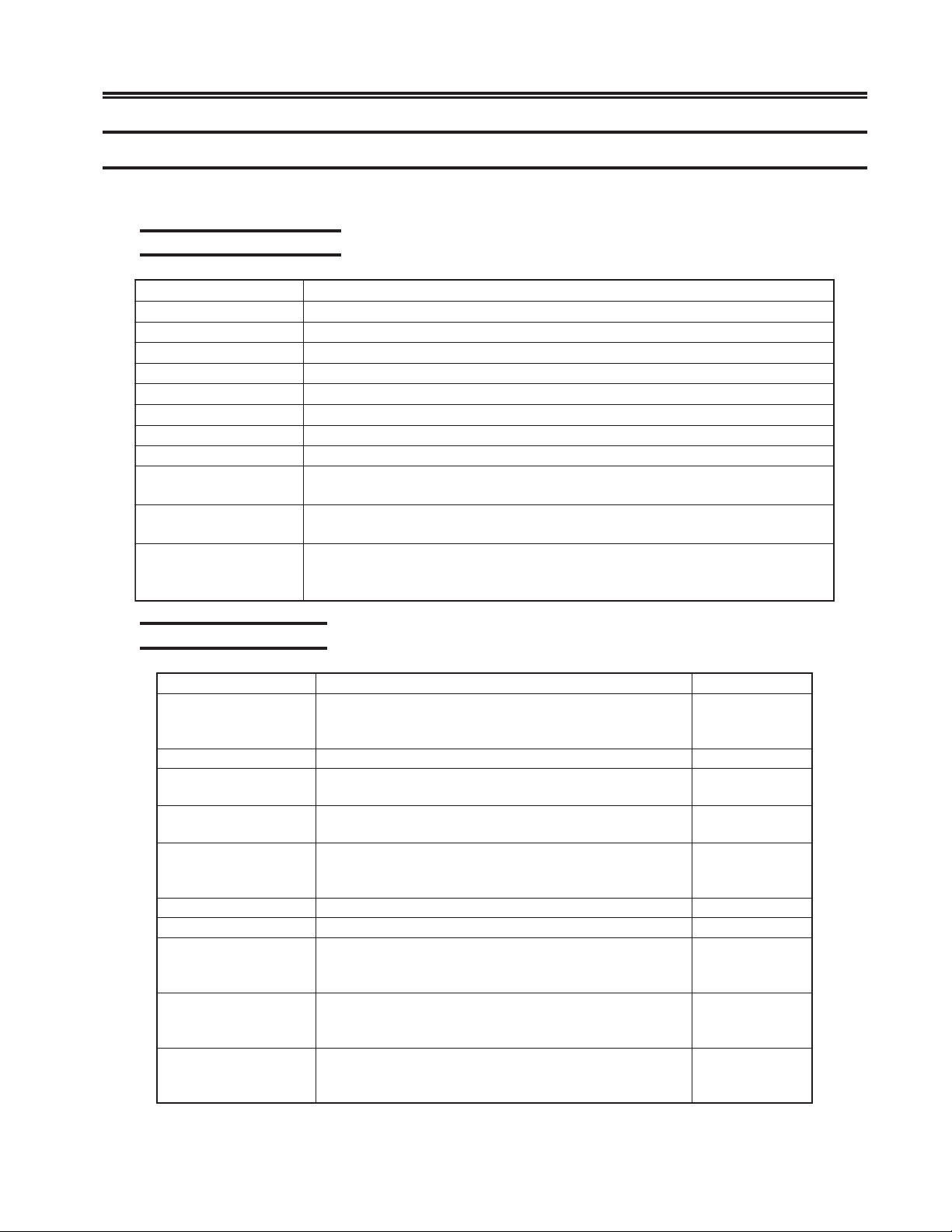
Hardware Components .................................................................................. 1-3
Standard Components ............................................................................... 1-3
Feature Components.................................................................................. 1-3
Chapter 2. Installation ............................................................................................. 2-1
Installation Checklist ..................................................................................... 2-1
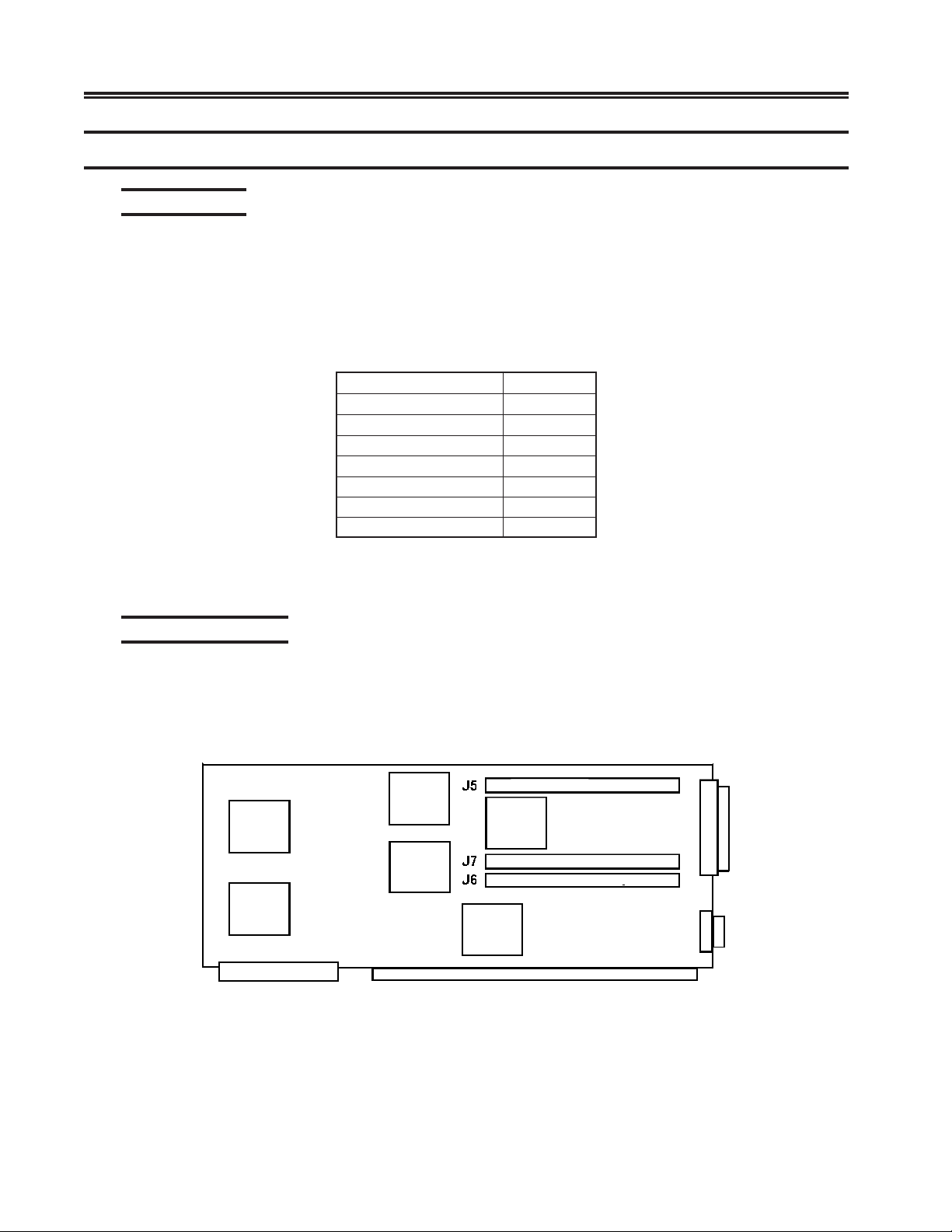
Memory ......................................................................................................... 2-2
Requirements............................................................................................. 2-2
Additional Memory ................................................................................... 2-2
Printed Circuit ............................................................................................... 2-3
Unpacking Additional Printed Circuit Boards (PCBs) .............................. 2-3
Installing/Removing Printed Circuit Boards (PCBs) --
by Authorized Service Personnel Only ..................................................... 2-3
Location Planning for the 25S/25L/28L/3074 ............................................... 2-4
Environmental Parameters......................................................................... 2-4
Power Requirements ................................................................................. 2-4
Supplied Cable Distances .......................................................................... 2-5
Power Cable Requirements............................................................................ 2-7
Serial 3270 Host Connection ......................................................................... 2-8
Token Ring Connection ................................................................................. 2-8
Ethernet Connection ...................................................................................... 2-8
10/100 Mbps Ethernet ............................................................................... 2-8
10BASE-T Operation ................................................................................ 2-8
100BASE-TX Operation ........................................................................... 2-9
LED Descriptions .................................................................................... 2-10
Local Channel Installation ........................................................................... 2-10
Switches/Indicators ................................................................................. 2-10
Cables ...................................................................................................... 2-11
Preparing for Installation......................................................................... 2-11
Connecting to the Channel ...................................................................... 2-11
Channel Board Installation ...................................................................... 2-14
Bus/Tag Cable Interfacing Assembly ...................................................... 2-14
Setting the Priority on the BTC ............................................................... 2-15
BTC-C Cabling ....................................................................................... 2-15
Local Channel Bypass ............................................................................. 2-16
707028-007 v
Page 6

SCON-25L/28L/3074 Console Concentrator
1174-25S Communications Server Hardware Reference Manual
ESCON Channel Interface........................................................................... 2-17
Indicators, Switches and Connectors ...................................................... 2-17
Attaching the ESC/ESX Interface to the Channel ................................... 2-18
RS232 Serial Interface ................................................................................. 2-18
Serial Port ................................................................................................ 2-18
High Speed Communication Interface......................................................... 2-19
Installation ............................................................................................... 2-19
Cabling .................................................................................................... 2-19
Slot Numbers ............................................................................................... 2-20
Slot Identification .................................................................................... 2-21
Board Slot Population.................................................................................. 2-21
Chapter 3. Operation ............................................................................................... 3-1
Controls ......................................................................................................... 3-1
Operator Panel ............................................................................................... 3-1
Indicators ................................................................................................... 3-1
Keypad ...................................................................................................... 3-2
IML ................................................................................................................ 3-4
Error Types .................................................................................................... 3-5
IML Errors (ERR___) ............................................................................... 3-6
Exception Errors (XCP___) ...................................................................... 3-6
Hardware Failures (FAIL___) ................................................................... 3-7
Online Errors ............................................................................................. 3-7
Error Indicators ......................................................................................... 3-7
Software Merge ............................................................................................. 3-8
Page
Chapter 4. Assembly Removal/Replacement .......................................................... 4-1
Introduction ................................................................................................... 4-1
Assembly Drawing ........................................................................................ 4-1
Field Replaceable Assemblies ....................................................................... 4-2
Removal/Replacement Procedures ................................................................ 4-3
Main Cover................................................................................................ 4-3
Circuit Board Assembly ............................................................................ 4-4
Operator Panel ........................................................................................... 4-4
Floppy Disk Drive ..................................................................................... 4-5
Hard Disk Drive ........................................................................................ 4-5
Power Supply Assembly............................................................................ 4-6
Back Panel and Expansion Back Panel Assembly .................................... 4-7
New Hardware Installation Procedures ......................................................... 4-7
Selecting Location for the New Board ...................................................... 4-8
Board Installation Procedure ..................................................................... 4-8
Index .................................................................................................................. Index-1
vi 707028-007
Page 7

Chapter 1. Introduction
SCON-25L General Description
The SCON-25L Console Concentrator is a powerful platform for supporting and managing multiple logical
partitions (LPARS) on mainframe hosts. The SCON-25L attaches to mainframes via one or two ESCON
adapters and is used to configure and monitor mainframe status. Up to 16 LPARS and 256 sessions can be
supported through each interface. The SCON-25L Console Concentrator supports LINCS software and is
part of the Visara Communication Server Hardware family. Client types supported on the 25L include up to
128 Coax displays and printers, up to 512 TN3270E clients, and up to 256 Telnet and/or LAN printer
clients.
SCON-28L General Description
The SCON-28L Console Concentrator is a powerful platform for supporting and managing multiple logical
partitions (LPARS) on mainframe hosts. The SCON-28L attaches to a mainframe via one or two ESCON
adapters, and is used to configure and monitor the mainframe status. Up to 64 LPARS and 256 sessions can
be supported through each interface (20 LPARs/ESCON come standard). The SCON-28L Console
Concentrator supports LINCS software and is part of the Visara Communication Server Hardware
family. Client types supported on the 28L include up to 128 Coax displays and printers, up to 512
TN3270E clients, and up to 256 Telnet and/or LAN printer clients.
SCON-3074 General Description
The SCON-3074 Console Concentrator is a powerful platform for supporting and managing large
numbers of LPARs on mainframe hosts. The SCON-3074 attaches to a mainframe via one or two
ESCON adapters, and is used to configure and monitor the mainframe status. Up to 48 LPARs and
128 sessions can be supported through each interface. The SCON-3074 Console Concentrator supports
LINCS software and is part of the Visara Communication Server Hardware family. Client types
supported on the SCON-3074 are up to 128 TN3270E, TN3270, and TN3287 clients, connected
through a pair of 10/100 Mbps Ethernet connections. Configuration and management of the SCON3074 is through the network using a Telnet connection.
1174-25S General Description
The 1174-25S Communication Server provides a number of communication services to provide
desktop to mainframe, mainframe to printer, and mainframe to server connections. A wide variety of
communication options and device attachments allows the 25S to take on many roles. A few of the
more common applications are described below. For more information describing the features
mentioned below, refer to the LINCS Planning, Configuration, and Central Control Manuals.
707028-007 1-1
Page 8

SCON-25L/28L/3074 Console Concentrator
1174-25S Communications Server Hardware Reference Manual
TN3270E Server
The 1174-25S functions as a TN3270E server, providing user desktops with access to a 3270
mainframe. The number of sessions supported can be scaled from 32 - 4048. With the implementation
of multiple 25S communication servers and the SMS feature, the TN3270E server function can be
spread across multiple platforms, encompassing tens of thousands of users, and providing fault
tolerance and load balancing as well.
Communications Concentrator
With the implementation of the SNA Gateway features, the 1174-25S can be used to gateway SNA
communications across a variety of communication links including ESCON, Bus and Tag channel,
100/10 Mbps Ethernet, 16/4 MBPS Token Ring, and synchronous serial connections (RS232, V.35,
X.21) up to T1/E1 speeds. Standard SNA as well as APPN is supported. Numerous card slots available
in the 25S allow extremely dynamic and complex networks to be accommodated. Using the gateway
functions provided by the 25S, it is easy to supplement and in some cases replace more expensive
Front End Processors. Downstream connections include Token Ring, Ethernet, Frame Relay, and
SDLC over a variety of serial connections and speeds.
Coax Terminal Server
The 25S supports up to 128 traditional fixed function coax terminals and printers, allowing up to 10
host sessions per terminal. Connections can be made using RG62AU coax or twisted pair. Host
connections to SNA hosts can be over ESCON, Bus and Tag channel, Ethernet, Token Ring, SDLC,
X.25 and Frame Relay. Non-SNA connections over ESCON, Bus and Tag channel, and BSC lines are
also supported.
LAN Printer Support
Up to 256 LAN printers can be supported through the 1174-25S, providing mainframe to LAN
printer connections. Traditional SNA printer definitions are converted to IP data streams which are
then directed to the appropriate LAN printer, anywhere in the network. LPR/LPD protocol as well as
the simpler socket connection method is supported.
Additional LAN Device Support
In addition to the device types listed above, the 25S can also support Telnet desktops (up to 256),
and IPX desktops (up to 4048), providing desktop to mainframe application support.
IP Channel Bridge
The 1174-25S can be configured to provide high speed LAN to mainframe communications for IP
traffic, using efficient bridging technology, and some filtering capabilities more commonly found in
routers.
1-2 707028-007
Page 9
Hardware Components
The following includes hardware, which may be installed.
Standard Components
metInoitcnuF
lenaPpO.tinuhtiwecafretnirotareposedivorP
BCPPCS.rossecorplortnocmetsyS
lenaPkcaB .dellifera2hc
C-PBE .)stols6folatot(sdraoberutaeflanoiti
PHV.rewopgnissecorpatadlanoitiddasedivorP
evirDdraH.egarotselifataD
polF.egarotselifataD
evirDyp
ylppuSrewoP.rewoptinusedivorP
BCPCSE
BCPXSE
BCPTEF
ivorP
Chapter 1. Introduction
ihwfostols7seilppus,sdraobdellatsnifonoitcennocretnisedivorP
ddatroppusotlenapkcabnoisnapxE
.skrowtenlennahcNOCSEotecafretninoitacinummocsed
.ylnoL52-NOCSnodradnats1
.skrowtenlennahcNOCSEotecafretninoitacinummocsedivorP
SdnaL82-NOCSnodradnatS1
.ylnosmroftalp)sdrac2(
.ylno4703-NOC
001/01elgnisahguorhttroppustneilcretnirpNALdna,tenleT,0723NTsedivorP
-NOCSdna,L52-NOCS,L82-NOCSnodradnatS,ecafretnitenrehtEspbM
4703
Feature Components
metInoitcnuFdellatsnI#.xaM
C-CTB*
.metsysbus
BCPPHC/CHC* .metsysbustnemhcattalennahcdraob-owT2
BCPTEF
BCPCSE
BCPCSH*
BCPCCS* .secived/stsohotsseccanoitacinummocsedivorP01
BCPCRT* .gnirnekototecafretninoitacinummo
CCM
xaoCrexelpitluM
rellortnoC
PHV
BCPXSE*
.skrowten
csedivorP9
sublennahcneewteb
ninoitacinummocsedivorP
.skrowtentenrehtE
).dellatsniebtsumSCNIL(
itroppustnemhcattadexelpitlumro
.tinuesabL52/S52nidradnats
)ylnOS52(.NPPArofderiuqerPHVlanoitiddA
-NOCSledoMnodellatsniebyaM.skrowten
.ylno4703-NOCS
noitcennocsedivorpelbacretpadalennahcdnaBCP
lennahcdraob-2dnaselbacgatdna
sbM001rosbM01otecafret
lennahcNOCSEotecafretninoitacinummocsedivorP
CLDSotecafretnisnoitacinummocetomerdeepshgiH
.senil4otpusedivorP.skrowtenyaleRemarFdna
secivedruofotpufotroppusrofyltceriddehcattaebnaC
.secived23otpugn
semocPHVenO.troppusrossecorplanoitiddasedivorP
lennahcNOCSEotecafretninoitacinummocsedivorP
dnaL82
2
7
2
7
4
2
2
* Not applicable to all models
707028-007 1-3
Page 10

Page 11

Installation Checklist
The following is a brief checklist of typical installation tasks. Detailed information
is provided later in this chapter.
1. Check the shipping carton for any obvious shipping damage prior to unpacking.
2. Unpack the unit per instructions provided with the shipping carton. This unit
weighs in excess of 50 lbs., so please take any necessary precautions such as
seeking help with lifting.
3. Place the unit in an appropriate location. Refer to “Environmental Parameters.”
4. Remove the cardboard protector (if present) from the disk drive. The unit
should not be powered on with a cardboard protector in the disk drive or the
disk drive may be damaged.
5. Inspect the unit for any physical damage.
6. Install (if required) and connect 3270 COAX, ESCON, Local Channel, Token
Ring, RS232, V.35 and/or Ethernet cables as needed.
Chapter 2. Installation
7. Ensuring that the Power switch on the front of the unit is off, plug the unit into
an appropriate AC outlet.
8. Turn the unit on (see Chapter 3, “Operation”). After a few seconds, messages
will appear on the LCD of the Operator Panel. These messages will change as
the unit proceeds through various IML states until it has completed the boot
up procedure. When the boot has completed, the word ‘CONFIGURATION’
should appear on the LCD. This initial boot process should take a few minutes
(less than 10). If the boot process has not completed, or if you see a message
that begins ‘ERR’ or ‘XCP’, then a failure of the boot process has occurred. If
a failure of the boot process occurs, you will want to contact your Service
Provider or the Visara Intellicenter for assistance. Removal of the covers by
unauthorized persons can void your warranty.
9. Configure the unit for use (see the LINCS Planning, Configuration, and Central
Control Manuals).
707028-007 2-1
Page 12
SCON-25L/28L/3074 Console Concentrator
1174-25S Communications Server Hardware Reference Manual
Memory
Requirements
The total amount of system addressable memory space across the bus is 27.5 Mb.
The unit comes standard with a full compliment of 8 Mb of common memory.
Each feature board installed contributes additional system memory. Configurations
exceeding 27.5 Mb are not supported.
The amount of memory address space each feature board requires is:
yromeMnommoCesaBBM8
CSHBM2
lennahClacoLBM2
gniRnekoTBM2
xaoC0723-CCMBM5.0
NOCSE-CSEBM4
tenrehtEtsaF-TEF*BM4/2
-XSEBM4
NOCSE
* The FET contributes either 2 MB or 4 MB of memory depending on the
feature combination configured.
Additional Memory
Memory is installed on the SCP card (slot 1) using 4-Mb memory modules. Local
memory is installed in J5, and 4 MB of Base Common memory in J6. Expansion
Common memory J7 is not used (see Figure 2-1). The other 4 MB of Base Common
memory is located on the VHP card, typically located in slot 2.
Figure 2-1. Memory Module Location, SCP Board
Local Memory
Not used
Base Common Memory
2-2 707028-007
Page 13

Printed Circuit
Some of the optional features require the installation of additional printed circuit boards.
WARNING
Due to electrical hazard, do not remove the system cover. Only qualified service
personnel may remove the system cover for service or installation of circuit cards.
Unpacking Additional Printed Circuit Boards (PCBs)
Follow these steps when you receive the shipment:
1. Inspect the carton for physical damage prior to unpacking.
2. If your PCBs packaging appears to have been damaged in shipment, please do
not open it. Rather, you should report the damage to the carrier upon delivery. If
you determine that your PCBs have concealed damage when you open the
package, report the damage to your carrier as soon as possible. In both situations,
you should also call Visara Customer Service to report the problem. Call
1-888-334-4380 or 1-919-882-0200.
Chapter 2. Installation
3. If you are unsure of who is providing your warranty or maintenance service,
then call the Visara Intellicenter.
4. If your PCBs fails to work properly during its initial installation or within 48
hours, please call the Visara IntelliCenter to report the problem. Call
1-888-334-4380 or 1-919-882-0200.
5. If no damage is noted, carefully remove and unpack the package contents.
Install the printed circuit board(s) as described below.
Installing/Removing Printed Circuit Boards (PCBs) -- by Authorized Service Personnel Only
Each Circuit board assembly is plugged into connector slots on the Mother board
and fastened to the chassis with a mounting screw.
1. Ensure power is off and disconnect AC power.
2. Remove the cover.
3. Remove the mounting screw and slot cover from the selected slot.
4. Slide the board into place and ensure the connector is seated properly.
5. Secure the board into place by installing the mounting screw
(removed in Step 3).
6. Connect all required cables to the Circuit board installed.
7. Reinstall the cover.
8. Reconnect AC power and turn the unit on.
It is required that any empty slot have a slot cover installed to provide proper
ventilation.
707028-007 2-3
Page 14
SCON-25L/28L/3074 Console Concentrator
1174-25S Communications Server Hardware Reference Manual
Location Planning for the 25S/25L/28L/3074
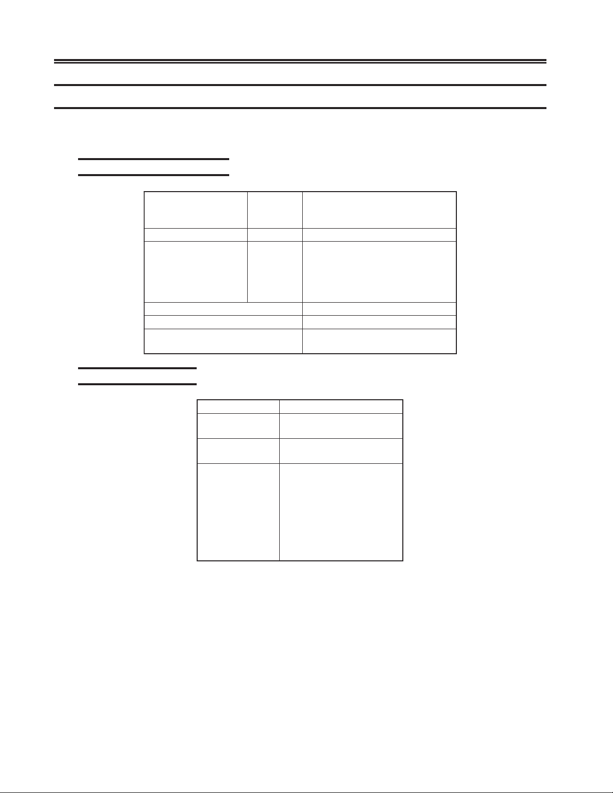
Use the following environmental parameters, power requirements, and cable
distance tables to select a location for your 25S/25L/28L/3074.
Environmental Parameters
:thgieW)gK5.32(bl8.15
secnaraelC
Power Requirements
snoisnemiD
:egnaRerutarepmeT)C°6.04ot°
:ytidimuHevitaleRnoitasnednoconhtiw%08ot%8
:tuptuOtaeH
:sesahP1
:rewoP
tloV
:htdiW
:htpeD
:thgieH
orF
:tn
:raeR
:poT
:tfeL
:thgiR
:gnitaRtnerruC
:)%01-/(ega
)mc5.44(ni5.71
)mc7.95(ni5.32
)mc9.22(ni9
)mc16(ni42
)mc13-52(ni21-01
)mc0(ni0
)mc01(ni4
)mc01(ni4
01(F°501ot°05
)lanimon(rh/UTB143
)mumixam(rh/UTB019
)gifnocesab(AV091
)mumixam(AV003
)zH06CAV511(A0.6
)zH05CAV032(A0.3
)zH1-/zH06/05ta(001
)zH1-/zH06/05ta(011
)zH1-/zH06ta(021
)zH1-/zH06/05ta(002
)zH1-/zH06ta(802
)zH1-/zH06/05ta(022
)zH1-/zH05ta(032
)zH1-/zH06/05ta(042
2-4 707028-007
Page 15
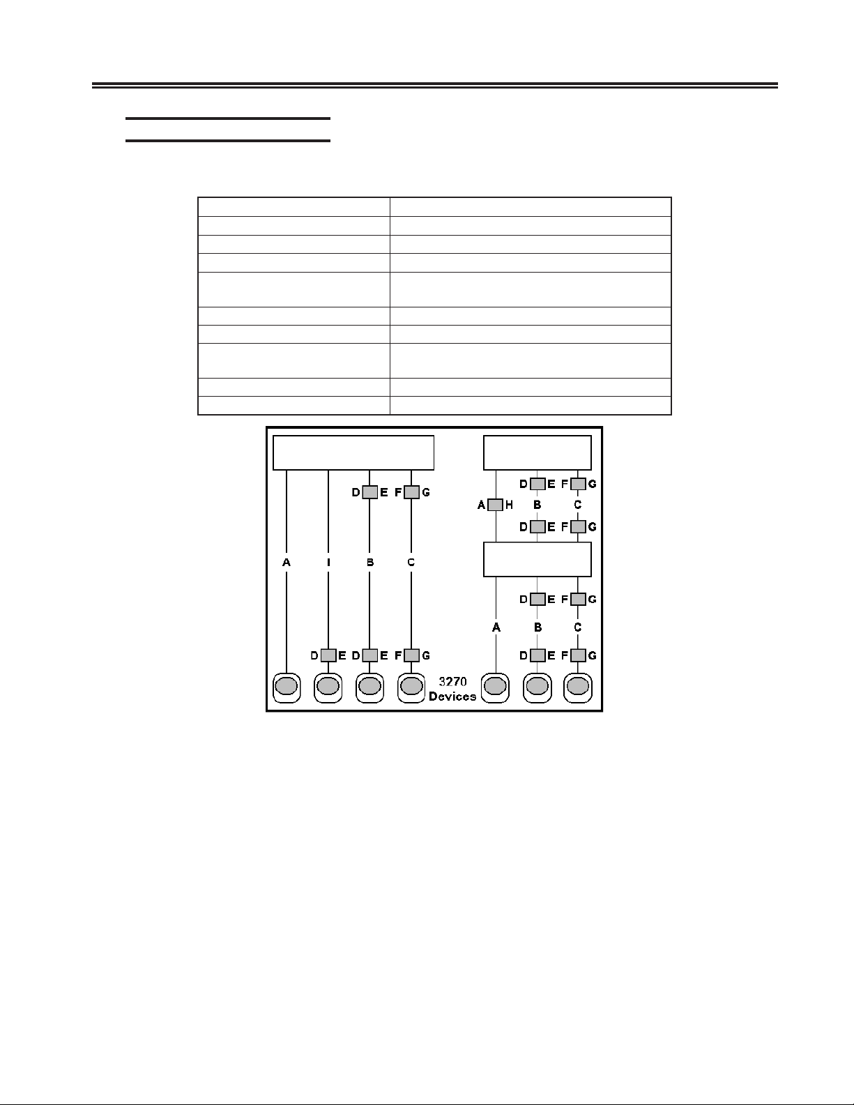
Supplied Cable Distances
The following table contains distance information for some types of cable:
epyTelbaC)sledomS52lla(ecnatsiDdeilppuS
elbaCrewoP.)m75.4(tf51
)CCSroF(elbaC53.V.ylnoelbacdeilppusynapmoCesU.)m6.7(tf52
selbaClennahC
)gaTdnasuB(
elbaCtenrehtE.detsilslaunamotrefeR
selbaCxaoC0723.detsilslaunamotrefeR
oT
CSHroF(elbaC53.V.ylnoelbacdeilppusesU.)m1.6(tf02
)
)CCSroF(232SR-AIE .ylnoelbacdeilppusesU.tf0
otedon(elbaCgniRnek
)]UAM[tinUsseccAaideM
)CSHroF(232SR-AIE.ylnoelbacdeilppusesU.)m1.6(tf02
1174/SCON 1174/SCON
4,tf03,tf02,tf01
lslaunamotrefeR
.detsi
Chapter 2. Installation
.wolebdetsilslaunamehtotrefeR
1199-2A/32
Figure 2-2. Coax Device Cable Types and Lengths
707028-007 2-5
Page 16
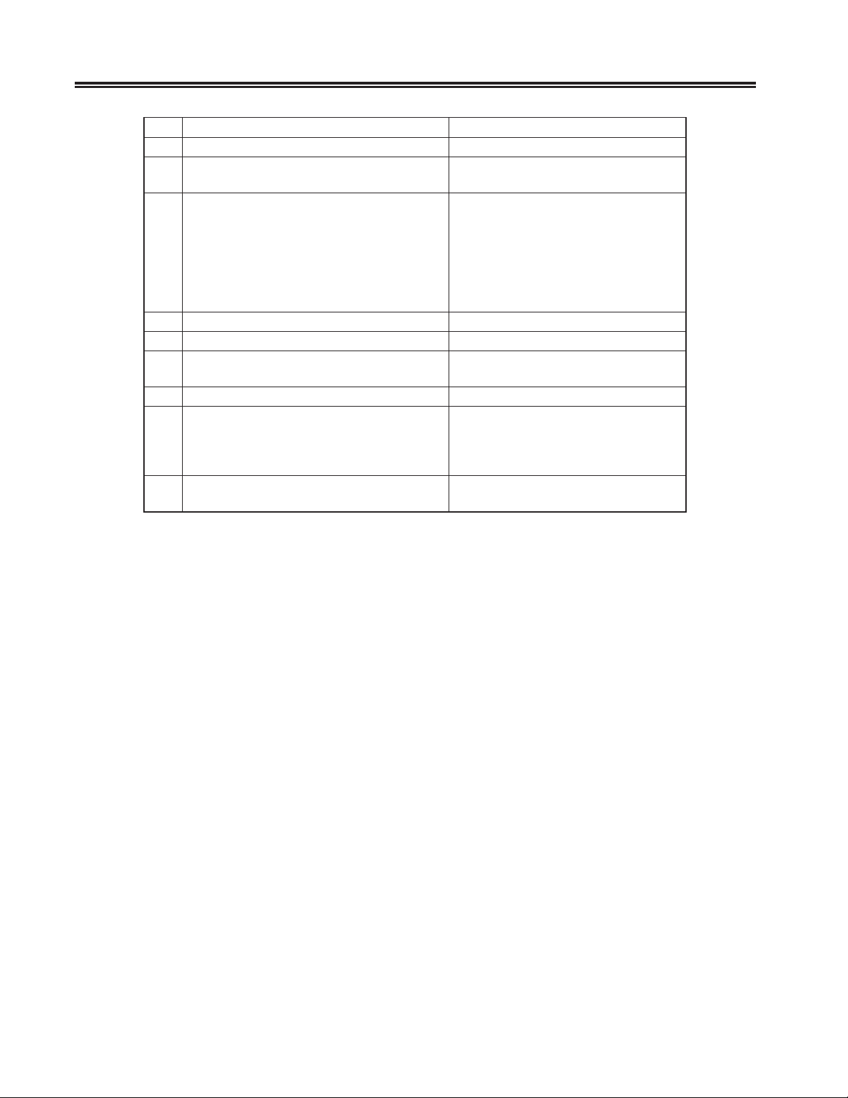
SCON-25L/28L/3074 Console Concentrator
1174-25S Communications Server Hardware Reference Manual
edoCrotcennoCro/dnaaideMelbaChtgneLelbaC
AelbaClaixaoC)m0051(tf0294
BaideMdeificeps3epyTMBI
C9dna,2,1sepyTmetsySgnilbaCMBI
DretpadAriaP-detsiwT-ot-xaoC0723)m5.5(tf81
ErotcennoC3epyTCPDMBI)m5.4(tf51
F
GelbaCtnemhcattArotcennoCesopruPlauD)m9(tf03ro)m4.2(tf8
H
I
nulaB
sAnulaBxaoC
cim521/05ro
nor
)revreSsnoitacinummoC
xaoCssel-elbaCroylbmes
,norcim521/5.26)revreSsnoitacinummoC
nidellatsniAWTevahtsum(eriWdetsiwT
01
:2dna1sepyT
ulab2htiW
nidellatsniADFevahtsum(elbaCcitpOrebiF
norcim041/0015epyTmetsySgnilbaCMBI
)m0051(tf0294
muminim)m5.03(tf0
mumixam)m572(tf009
)m0051(tf0294-snulab0htiW
)m0001(tf0823-nulab1htiW
)m016(tf0002-snulab2htiW
)m0001(tf0823-snulab0htiW:9epyT
)m766(tf6812-nulab1htiW
)m604(tf3331-sn
)m9.4(tf61ro)m4.2(tf8
When using fiber optic cable, a Fiber Optic Device Adapter must be installed in the
Communications Server. Note that when using Type 3 media, a connector with a special
actuator and filter (such as IBM’s DPC-T3) is required in order to connect devices
equipped with a DPC. Otherwise, a Balun assembly is used.
The following limitations apply to the use of these devices:
1. (coax length) + (5 * twisted pair length) <= 4500 ft (1375 m)
2. (minimum twisted pair length) => 100 ft (30.5 m)
Additional information about cable types and distances is available in the following
Publications:
• Using the IBM Cabling System with Communication Products, GA27-3620
• IBM Cabling System Planning and Installation Guide, GA27-3361
• IBM System/360 and System/370 I/O Interface Channel to Unit Original Equipment
Manufacturers’ Information, GA22-6974
• A Building Planning Guide for Communication Wiring, G320-8059
• IBM Enterprise Systems Architecture/390, ESCON I/O interface, and Physical Layer
specification SA23-0394
2-6 707028-007
Page 17

Power Cable Requirements
For units operating at 100-120V: The power cable required for domestic units is a
UL listed, CSA certified, 18/3 AWG, SJT, cable (15-foot [4.6-meter] maximum). It
is terminated on one end by a 125V, 15A grounding type attachment plug. It is
terminated at the other end by a 125V, 15A parallel blade, grounding type attachment
plug.
For units operating at 200-240V: The power cable required for domestic units is a
UL listed, CSA certified, 18/3 AWG, SJT, cable (15-foot [4.6-meter] maximum). It
is terminated on one end by a 250V, 15A grounding type attachment plug. It is
terminated at the other end by a 250V, 15A tandem blade, grounding type
attachment plug.
The power cable required for international units is an 18/3 AWG, type SJT, cable
(15-foot [4.6-meter] maximum). It is terminated on one end by a 250V, 15A
grounding type attachment plug body. It is terminated at the other end by a 250V,
15A grounding type cord connector. The cord set is marked HAR to signify
appropriate safety approvals. The socket outlet must be nearby and easily accessible,
per IEC 950 Sec. 1.7.2.
Chapter 2. Installation
The installation site must provide a properly wired and grounded power outlet.
Circuits connected to air conditioners and devices that generate significant transient
electrical noise should be avoided.
Electrostatic discharge in the vicinity of the unit should be minimized by avoiding
high resistance floor material and carpeting that does not have antistatic properties,
avoiding the use of plastic seats and covers, and avoiding low humidity levels. The
unit should be located away from areas that generate electromagnetic interference
(for example, transformers, power distribution panels, and motors). The unit should
not be installed where the atmosphere contains corrosive elements that may damage
the unit.
Cable runs should avoid areas that produce electromagnetic interference (for
example, near transformers, switching equipment, power distribution panels, and
under carpets where vacuum cleaning is done). Also, heavy equipment should not
be moved or rolled over the cable.
707028-007 2-7
Page 18
SCON-25L/28L/3074 Console Concentrator
1174-25S Communications Server Hardware Reference Manual
Serial 3270 Host Connection
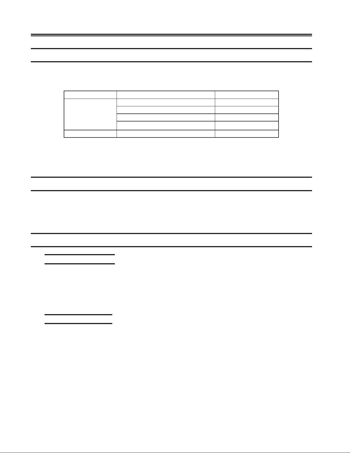
For each 3270 host-to-unit line, you must use one of the following special
Company sourced cables:
elbaCrebmuNtraPrebmuNURF
232-SRAIE
53.V100-031112100-166659
Failure to use specified cables may result in damage to the SCC board(s).
010-821112elbaliavAregnoLoN
020-821112020-066659
030-821112elbaliavAregnoLo
040-821112040-066659
WARNING
N
Token Ring Connection
The Token Ring Interface cable can be attached directly to the Token Ring Media
Access Unit (MAU), or can be extended by attaching it to another cable that is
attached to the MAU. The unit attachment point is at the TRC board using a 9-pin
D connector.
Ethernet Connection
10/100 Mbps Ethernet
The single RJ-45 connector on the network cable supports 10 Mbps or 100Mps
speeds. NWAY auto-negotiation enables the 10/100Mbps Ethernet NICs to
automatically run at the speed that the connected hub supports. The 10/100 Mbps
Ethernet NICs works with products that comply with IEEE 10BASE-T and 100
BASE-TX specifications.
10BASE-T Operation
10BASE-T is the Institute of Electrical and Electronics Engineers (IEEE) 802.3
standard for Ethernet signaling over unshielded twisted-pair wire at 10 Mbps.
Ethernet, as the most widely used network protocol, uses 10BASE-T as its primary
cabling scheme. Ethernet’s characteristics include:
• A data rate of 10 Mbps.
• A broadcast architecture.
• A specific media-access control (MAC) scheme.
The 10BASE-T name indicates a signaling speed of 10 Mbps and twisted-pair wiring.
Base stands for baseband, which denotes a technique for transmitting signals as directcurrent pulses rather than modulating them onto separate carrier frequencies.
2-8 707028-007
Page 19
A wiring topology using 10BASE-T specifies a wiring hub, cable arranged in a
star configuration, and unshielded twisted-pair cable. Each node has a separate
cable run that must not exceed 100 meters (328 ft) from the node to the hub.
100BASE-TX Operation
100BASE-TX is the IEEE 802.3u standard for Fast Ethernet signaling over Category
5 UTP or STP wire at 100 Mbps.
Based on an extension to the IEEE 802.3 Ethernet specification, Fast Ethernet’s
characteristics include:
• A data rate of 100 Mbps.
• A broadcast architecture.
• A specific media-access control (MAC) scheme.
A wiring topology using 100BASE-TX specifies a wiring hub, cable arranged in a star
configuration, and Category 5 UTP or STP wiring. Each node has a separate cable run
that must not exceed 100 meters (328 ft) from the node to the hub.
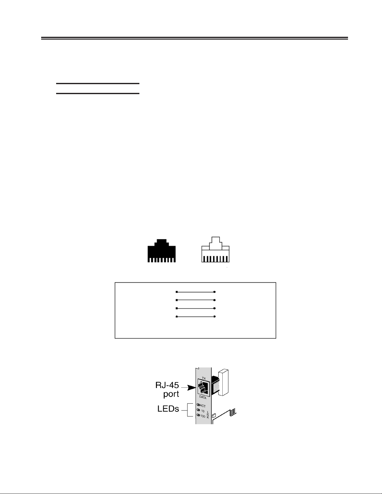
Figure 2.3 shows the RJ-45 connector pin assignments for the 10/100 Mbps
Ethernet NIC.
Chapter 2. Installation
Port Connector
8 7 6 5 4 3 2 1 1 2 3 4 5 6 7 8
TxD+
TxD-
RxD+
RxD-
1
2
3
6
Pins 4, 5, 7 and 8 are not used
1
2
3
6
TxD+
TxD-
RxD+
RxD-
Figure 2.3 RJ-45 Connector Pin Assignments
Figure 2.4 LEDS
707028-007 2-9
Page 20
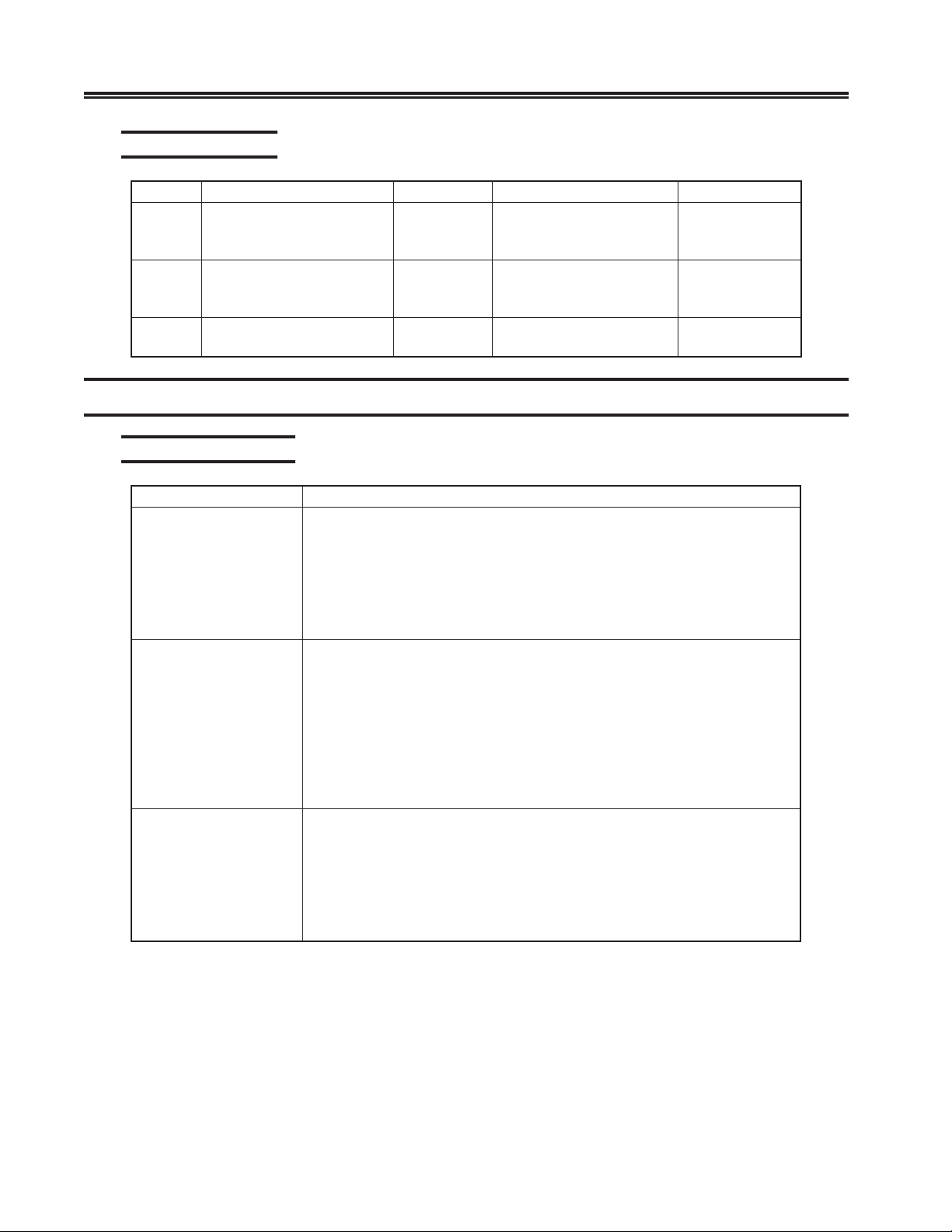
SCON-25L/28L/3074 Console Concentrator
1174-25S Communications Server Hardware Reference Manual
LED Descriptions
DELnoitpircseDgnihsalFydaetSFFO
desreveR
ytiralop
desreveR
ytiralop
krowteN
eb
buhdna
tneserpciffart
buhdnaCINneewt
XT-ESAB001dooG
ciffartkrowtenyvaeHciffartoN
TCA
KNL01ytirgetniKNL:neerG
KNL001ytirgetniKNL:neerG
rehtierofciffarttroP:wolleY
deeps
Local Channel Installation
Switches/Indicators
emaNnoitcnuF
rotacidnIenilffO
.lennahcehtotdetcennocsitinuehtnehwffo
noitcennocT-ESAB01dooG
buh
CINneewtebnoitcennoc
buh
noitcennocoN
dnaCINneewteb
noitcennocoN
dnaCINneewteb
yek-3A.slennahctsohllamorfdetcennocsidyllacigolsitinuehttahtsetacidnI
nilffOroenilnOlennahcaselggotlenaprotarepoehtmorfecneuqes
ehT.e
sirotacidnieht;lennahcehtotdetcennoctonsitinuehtnehwtilsirotacidni
GNINRAW
.ffosirotacidnienilffOehtnehwffoderewopebrevendluohstinuehT
sihctiwsytiroirPehT.lennahcehtnotinuehtfoytiroirpehtyficepsotdesU
roytiroirPhgiHtcelesottesebyamhctiwsehT.draobC-CTBehtnodetacol
.ytiroirPwoL
hctiwSytiroirP
.langislennahctuOtceleSehtybdellortnoc
inulortnocehtsesuacgnittesytiroirPwoLehT
.langislennahcnItceleSehtybdellortnoc
ehT.draobCHCagnillatsnirognivomererofebhctiwssihtesU
.)elbac-V(elbacretpadalennahcehtnodetacolsi
hctiwSssapyB
celesehtniniamersyawladluohshctiwsssapyB
.)S(noitisopt
ebotnoitcelesdetaitinitinulortnocehtsesuacgnittesytiroirPhgiHehT
ebotnoitcelesdetaitinit
hctiwsssapyB
tinuehtdnuoraslangistceleslennahcehtetuorerotdesusihctiwsssapyBehT
detcelessinoitcnufssapybehT.tnemecalperrofdevomerebnacdraobehtos
eht,noitarepolamronroF.noitisop)B(nOssapyBehtothctiwsehtgnittesyb
2-10 707028-007
Page 21
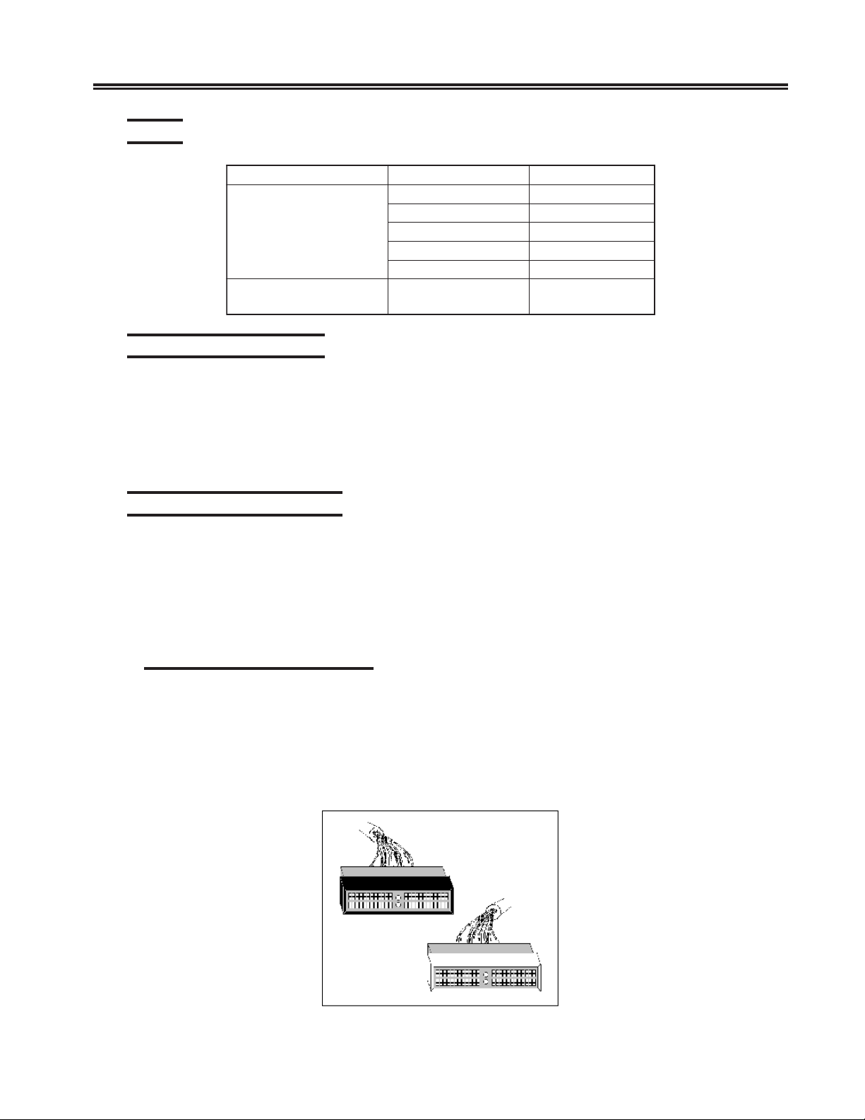
Cables
elbaCrebmuNtraPhtgneL
elbaClennahC
)gaTdnasuB(
)elbaC-V(
Preparing for Installation
Ensure that the following are available:
• Channel board(s)
• CHC and CHP boards installed
• BTC-C board
• Channel Adapter Cable
• Channel (Bus and Tag) Cables
Chapter 2. Installation
1051079)m75.4(tf51
7600079)m1.6(tf02
2051079)m1.9(tf03
7511079)m42
977803)m84.03(tf001
elbaCretpadAlennahC
100-40792
.51(tf05
Connecting to the Channel
To connect the unit to the channel:
• Contact the customer’s System personnel to determine the required setting of the
Priority switch. Set the Priority switch.
• Install BTC-C board in rack if desired.
• Connect Channel Adapter cable between the CHC board and the BTC-C.
• Connect the Channel (Bus and Tag) cables.
Connect the Channel Cables
The two channel cables (Bus and Tag) provide the electrical connection of all data and
control signals between the channel and the 25S.
Each cable has a light colored end and a dark colored end. The light colored end must
be attached to Bus In or Tag In receptacles. The dark colored end must be attached to
Bus Out or Tag Out receptacles.
Figure 2-5. Bus/Tag Cable Ends
707028-007 2-11
Page 22
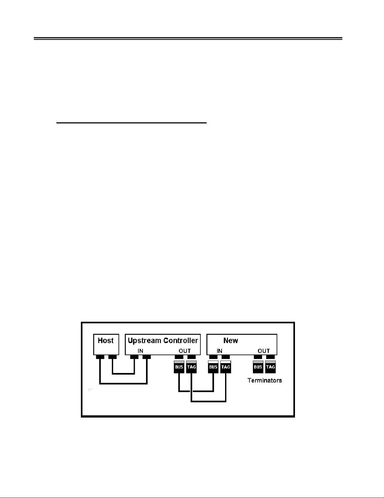
SCON-25L/28L/3074 Console Concentrator
1174-25S Communications Server Hardware Reference Manual
Prior to installing a new set of cables, you should label both ends of one cable Bus
and both ends of the remaining cable Tag to ensure that you attach the cables to
the proper receptacles.
The unit may be connected to the end of a channel, the middle of a channel, or
replace an existing unit on a channel. Follow the instructions appropriate for your
installation.
Connecting a Unit to the End of a Channel
Refer to Figure 2-6.
1. Ensure that the host processor/channel is in a stop state before disconnecting
any channel cables or terminator blocks.
2. Label each end of one of the new channel cables Bus; label each end of the
other new channel cable Tag.
3. Connect the light colored ends of the new Bus and Tag cables to the Bus In
and Tag In receptacles on the BTC-C
4. Remove the terminator blocks from the existing unit at the end of the channel.
Ensure that they are identified as Bus and Tag as they are removed so they will be
reconnected in the correct receptacles.
5. Connect the dark colored ends of the new Bus and Tag cables to the Bus Out and
Tag Out receptacles of the existing unit.
6. Connect the terminator blocks to the Bus Out and Tag Out receptacles of
the BTC-C.
Note: If unit fails to communicate when positioned on the end of the channel, it
is suggested that you try locating it in another position on the channel.
Some non-Visara controllers that are positioned on the end of the channel
utilize an internal channel terminator, and the channel signals are not
propagated beyond itself.
Unit
Figure 2-6. Connecting to the End of a Channel
2-12 707028-007
Page 23
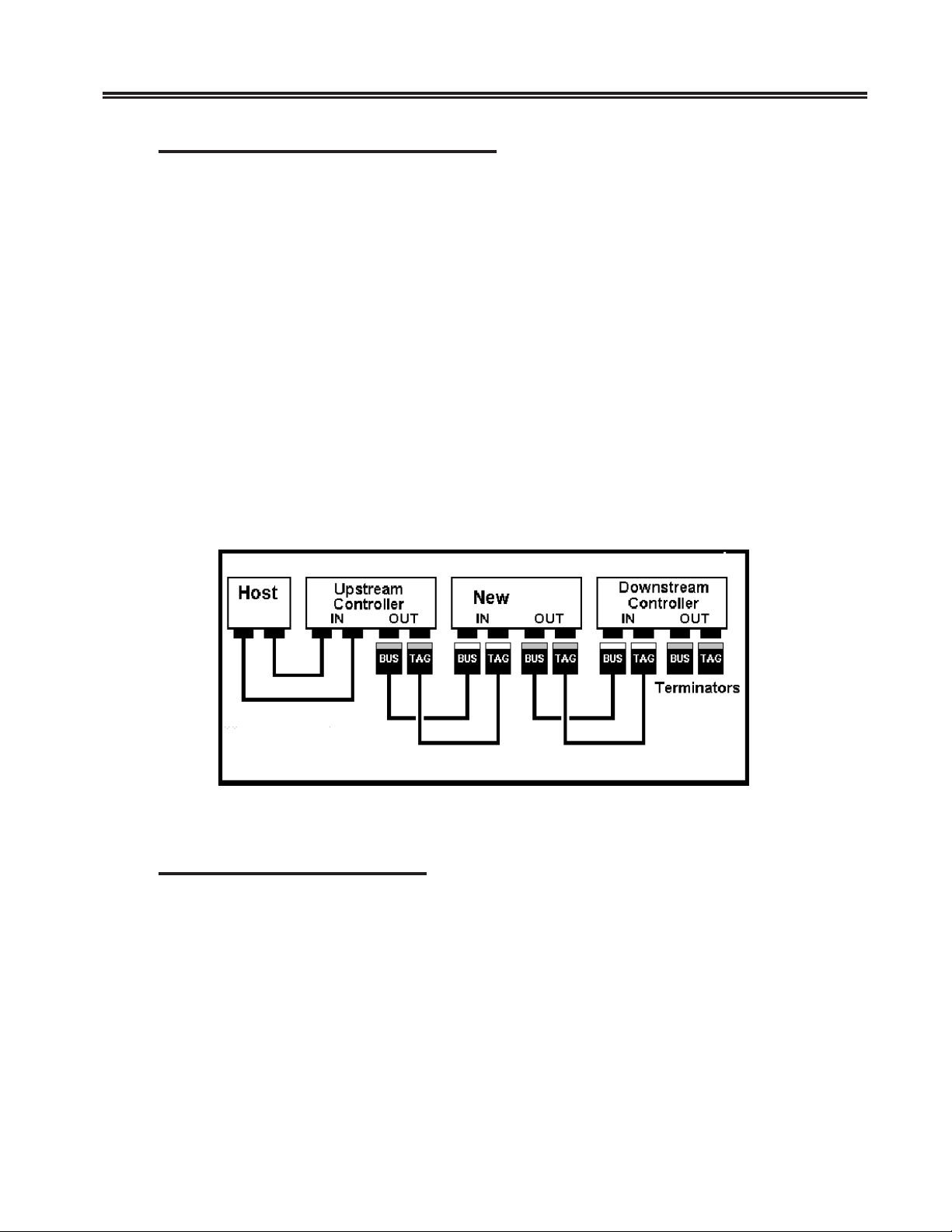
Chapter 2. Installation
Connecting to the Middle of a Channel
Refer to Figure 2-7.
1. Ensure that the host processor/channel is in a stop state before disconnecting
any channel cables or terminator blocks.
2. Label each end of one of the new channel cables Bus; label each end of the
other new channel cable Tag.
3. Connect the light colored ends of the new Bus and Tag cables to the Bus In
and Tag In receptacles on the BTC-C.
4. Disconnect the existing Bus and Tag cables from the Bus Out and Tag Out
receptacles of the existing unit upstream of the final location of the unit. Ensure
that the cable ends are identified as Bus and Tag as they are removed so they will
be reconnected in the correct receptacles.
5. Connect the dark colored ends of the new Bus and Tag cables to the Bus Out and
Tag Out receptacles of the existing unit upstream of the final location of the unit.
6. Connect the existing Bus and Tag cables to the Bus Out and Tag Out receptacles of
the BTC-C.
Unit
Figure 2-7. Middle/Replacement Connection to Channel
Replacing a Unit on a Channel
Refer to Figure 2-7.
1. Ensure that the host processor/channel is in a stop state before disconnecting any
channel cables or terminator blocks.
2. Disconnect the existing Bus and Tag cables from the Bus Out and Tag Out
receptacles of the existing unit. Ensure that the cable ends are identified as Bus and
Tag as they are removed so they will be reconnected in the correct receptacles.
These cables have dark colored ends.
707028-007 2-13
Page 24
SCON-25L/28L/3074 Console Concentrator
1174-25S Communications Server Hardware Reference Manual
3. Disconnect the existing Bus and Tag cables from the Bus In and Tag In
receptacles of the existing unit. Ensure that the cable ends are identified as
Bus and Tag as they are removed so they will be reconnected in the correct
receptacles. These cables have light colored ends.
4. Connect the Bus and Tag cables removed in Step 3 to the Bus In and Tag In
receptacles of the BTC-C. These cables will have light colored ends.
5. Connect the Bus and Tag cables removed in Step 2 to the Bus Out and Tag Out
receptacles of the BTC-C. These cables will have dark colored ends.
Channel Board Installation
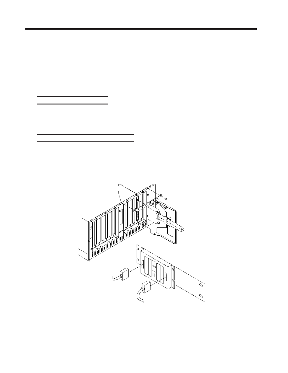
The CHC and CHP boards are installed in the card cage. A cable strain relief
bracket is attached to the chassis. A BTC-Cabled (BTC-C) assembly is used for
channel cable interfacing.
Bus/Tag Cable Interfacing Assembly
The BTC-Cabled board (BTC-C) assembly is a rack-mountable board providing
channel cabling. A Channel Adapter cable (V-cable) for connection between the
BTC-C and CHC is required. The V-junction connector of the cable is attached to
the CHC. Each end of the V-cable is keyed to attach to the appropriate receptacle
on the BTC-C.
Figure 2-8. BTC-Cabled Board Installation
2-14 707028-007
Page 25
Setting the Priority on the BTC
Determine the priority for the unit and set the priority with the switch(es) located
on the BTC-C. The priority of connection for each unit on the channel is determined
by switch settings on the BTC-C and the physical position the unit occupies on the
channel.
During normal network operation, the order of priority is (from highest to lowest):
1. All units set to High Priority, starting at the host processor and moving to the
last unit on the channel, followed by
2. All units set to Low Priority, starting from the last unit on the channel and
moving back to the mainframe.
Setting the priority to High allows the unit to attain connection to the channel
before units set to Low priority (for control unit initiated channel sequences).
Setting the priority to Low causes the unit to attain connection to the channel after
units set to High priority (for control unit initiated channel sequences).
Chapter 2. Installation
Channel priority is set with a switch located on the BTC-C board. Set the switch
on the BTC-C board to the appropriate position for the desired priority. Bypass is
set using a switch located on the V-junction connector of the Channel Adapter
cable. Refer to Figure 2-8.
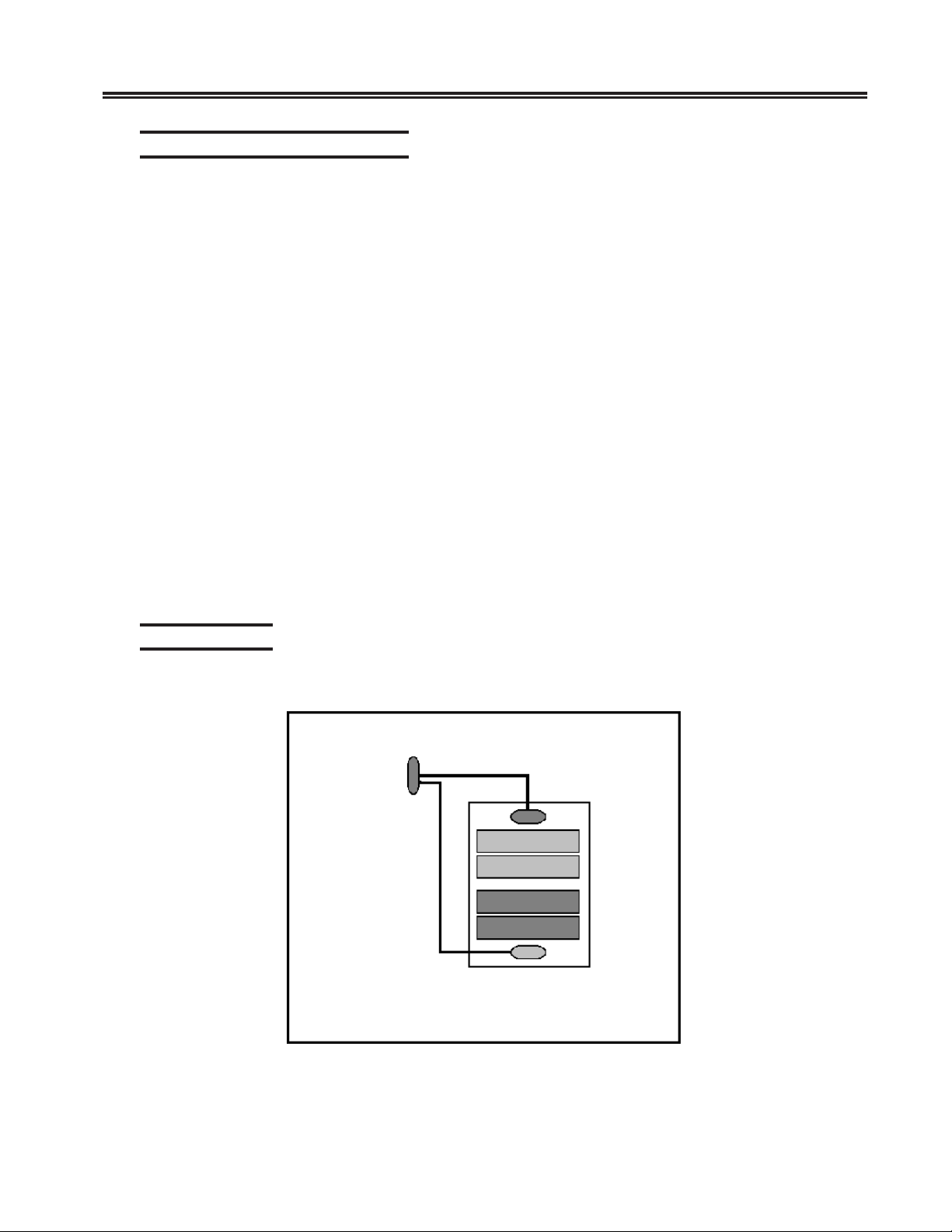
BTC-C Cabling
Typical BTC-C and CHC/CHP board cabling is shown in Figure 2-9.
To CHS or
CHC at
J3 or J8
V-Cable
BTC-C Assembly
Figure 2-9. BTC-C Typical Cabling
707028-007 2-15
Page 26
SCON-25L/28L/3074 Console Concentrator
1174-25S Communications Server Hardware Reference Manual
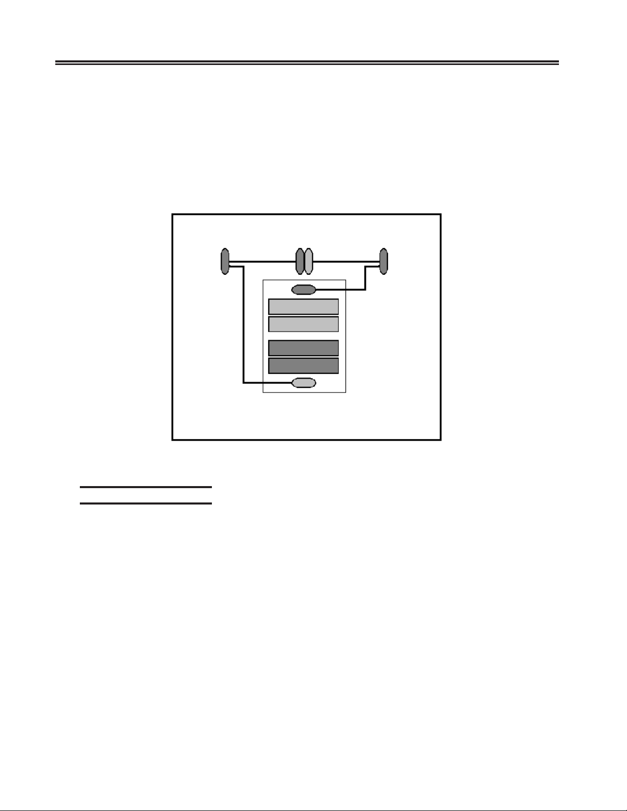
Utilizing the BTC-C assembly, two channel adapter cables (V-cables), and two
sets of channel boards provides a cabling option (Figure 2-10) for connecting the
25S to a single local channel configured for one of the following:
SNA and non-SNA protocols on the same channel
OR
Up to 64 ports configured on a non-SNA channel.
To CHS or
CHC at J3
Figure 2-10. BTC-C Single Channel Cabling Option
Local Channel Bypass
Bypass is used to remove the unit from the local channel without interrupting the
channel communication link to other units/hosts. The Bypass function allows local
troubleshooting of the network unit without interfering with the local channel
communication link.
To CHS or
CHC at J8
V-CableV-Cable
BTC-C Assembly
Use the following procedure to set Bypass.
1. Place the unit offline (for each channel if a 2-channel configuration) by pressing
the Shift key, followed by the Enter key, followed by the channel number (1 or 2).
2. Wait for the offline messages and indicators to light confirming an offline condition.
Refer to Chapter 3, “Operation.”
Note: Powering off the unit while either offline LED is not on may result in host
system problems.
2-16 707028-007
Page 27

Chapter 2. Installation
3. Ensure that the host processor/channel is in a stop state.
4. Set switches to Bypass to isolate the unit from the local channel. The Bypass
switch for the BTC-C assembly is located on the V-junction connector of the
Channel Adapter cable (Figure 2-8).
Note: The Bus/Tag cables must remain connected to the BTC-C for the
communication link to remain intact.
5. The host processor/channel may now be removed from the stop state.
6. Local testing and/or service may be performed on the unit.
When testing or service is complete, use the following procedure to return the unit
to service on the channel.
1. Place the host processor/channel in a stop state.
2. Reset the Bypass switch to normal state and set the priority.
3. Place the host processor/channel in a start state.
4. Follow normal power-on procedures.
ESCON Channel Interface
An ESCON Controller (ESC or ESX), a PCI Feature Adaptor (PFA) board with a
Luminex ESCON board permanently connected/mounted in place, provides a single
ESCON Channel communications interface. The ESC provides a single channel
attachment interface for connecting 25S/25L Communication Servers to an ESCON
director or to a mainframe channel. The ESX provides a single channel attachment
interface for connecting 28L/3074 communication servers to an ESCON director
or to a mainframe channel.
The fiber connection from the mainframe to the CARD shall be multimode 62.5/
125 micron cable for distances up to 3 kilometers with no directors, or 9 to 26
kilometers with 2 ESCON directors in series. Multimode 50/125 micron cable
may also be used for distances up to 2 kilometers with no directors, or 6 to 24
kilometers with 2 ESCON directors in series.
Indicators, Switches and Connectors
Indicators, switches and connectors are found on the front and top edge of the
Board. A view of the ESC/ESX faceplate bracket cutout is shown below.
Indicators
IRQ (amber): This is the Interrupt Request LED. When the ESCON card generates
an interrupt to the PFA PCI host card, this LED will be lit. When the PCI host
acknowledges the interrupt, the LED is turned off.
ACTV (green): This LED is lit when the Channel Fiber Optic Interface is actively
communicating on the channel.
707028-007 2-17
Page 28

SCON-25L/28L/3074 Console Concentrator
1174-25S Communications Server Hardware Reference Manual
ONLN (green): This is the ONLINE LED. This LED is lit when the Channel Interface
is logically connected to the channel. The Channel Interface must be on-line to respond
to selections by the mainframe. The Channel Interface cannot go on-line if the channel
is disconnected or down.
FAIL/ERR (amber): This is the FAIL LED. This LED is lit at power up, but goes off
within 5 seconds if the Power-up Self-Test (POST) passes. During normal operation
this LED is lit if the receive ESCON signal is not present or is invalid.
Switches
Debug SW: Recessed push-button switch. Pressing this switch causes the on-board
code to enter a special debug mode (monitor). The debug mode should only be used
under the direction of a Visara Engineer. If the debug mode is entered, the board will no
longer operate normally on the channel. If the debug switch is accidentally pressed, the
ESCON card should be reinitialized (re-download software). Please note that
reinitializing the ESCON card may require the 25S/25L/28L/3074 to be IMLed.
Connectors
Fiber Optic Transceiver: This connector is used for attachment of ESCON fiber
optic cable.
Attaching the ESC/ESX Interface to the Channel
Follow the steps below, to connect an ESCON cable between the ESCON host channel
and the 25S/25L/28L/3074:
1. Vary off-line the host channel that will attach to this ESC. Refer to your
mainframe operating system manuals for instructions.
2. Connect an ESCON fiber optic cable between the 25S/25L/28L/3074 and
the host.
3. Vary online the host channel.
4. A “505-01” connection code on the 25S/25L/28L/3074 display indicates that
proper communication is established. Connection problems may exist if the
plug does not click when placed into the ESC receptacle. Ensure the ESCON
plug is not loose.
RS232 Serial Interface
Serial Port
A serial port is provided with the ESC, FET and VHP cards, but is not functional.
2-18 707028-007
Page 29
High Speed Communication Interface
The High Speed Communications (HSC) board provides a high-speed-remote
communications interface to SDLC and Frame Relay Networks. Each HSC board
provides up to four high speed channels.
Installation
Refer to Chapter 2, Installing/Removing PCBs.
WARNING
The 25S Communications Server must be powered off before connecting or
disconnecting the HSC adapter cable or the PLIMs. Failure to do so may result in
damage to the hardware.
Cabling
The HSC feature includes an HSC Adapter Cable (HAC). One end attaches to the
HSC board, the other end splits into four connectors. Each connector provides a
communication line capable of operating at full-duplex speeds up to 8 Mbps.
Chapter 2. Installation
The physical layer interface type is selected using a physical layer interface module
(PLIM) and one of four HSC communication cables. The PLIM1 supports either RS232
or V.35 communication protocol. The type cable used determines the protocol type.
Any combination of PLIMs and/or cables may be connected to the HSC board.
selbaC
020-117869232SRETD
020-217869232SRECD
020-31786953.VETD
020-41786953.VECD
020-51786912.XETD
Note: The cable assemblies supplied for use with the HSC board and PLIMs are
proprietary cables that may include EMI suppression components. For correct
operation and continued agency compliance do not substitute any other cables.
The DCE cables allow direct connection to DTE devices; no modem or modem
eliminator is required. When a DCE interface is selected, the HSC should be
configured to generate the transmit clock. Baud rates up to 1 Mbps are supported
and configured on the HSC line panels.
707028-007 2-19
Page 30
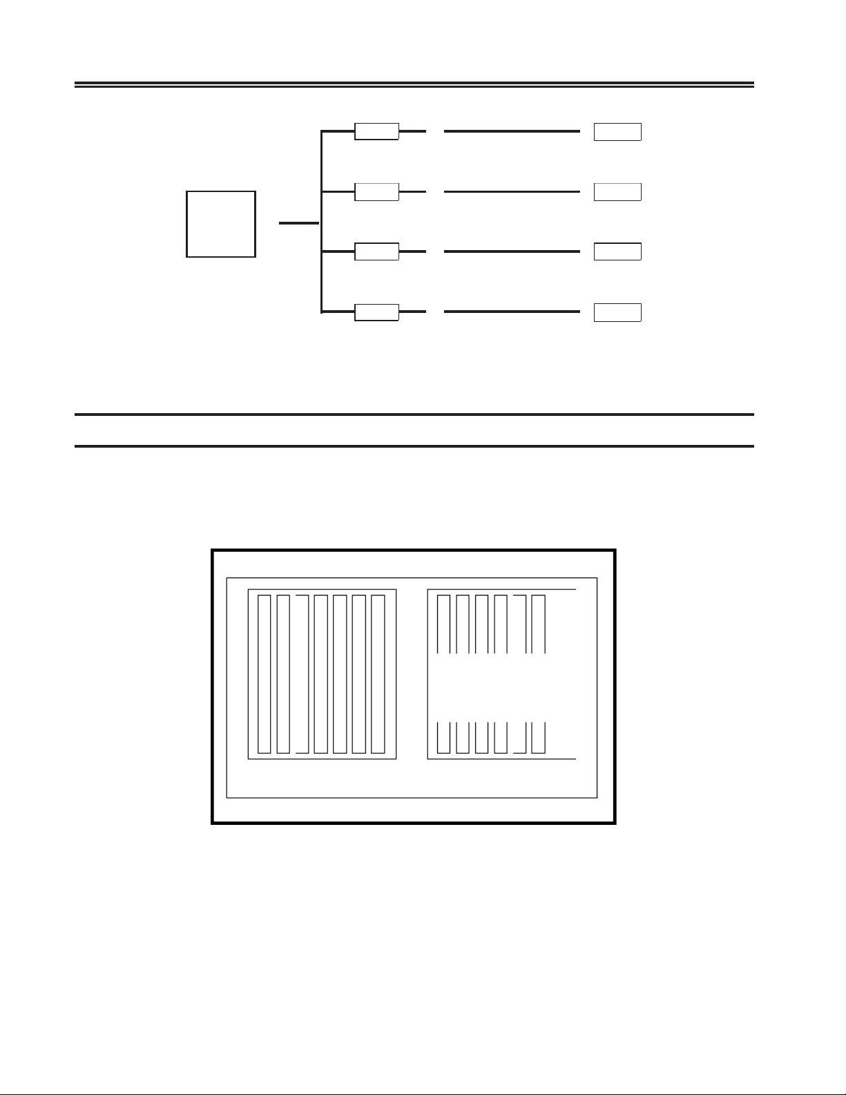
SCON-25L/28L/3074 Console Concentrator
1174-25S Communications Server Hardware Reference Manual
PLIM1
PLIM1
HSC
HAC
PLIM1
PLIM1
Figure 2-11. Sample HSC Installation
RS232 DTE
Comm Cable
RS232 DCE
Comm Cable
RS232 DTE
Comm Cable
V.35 DCE
Comm Cable
Slot Numbers
Modem
1174
Modem
1174
Many of the printed circuit boards for the unit are located in partitions called slots,
which are identified with numbers. The slots are sometimes specified by error messages
that permit the easy identification of a failing PCB. Figure 2-12 shows the locations of
the physical slots.
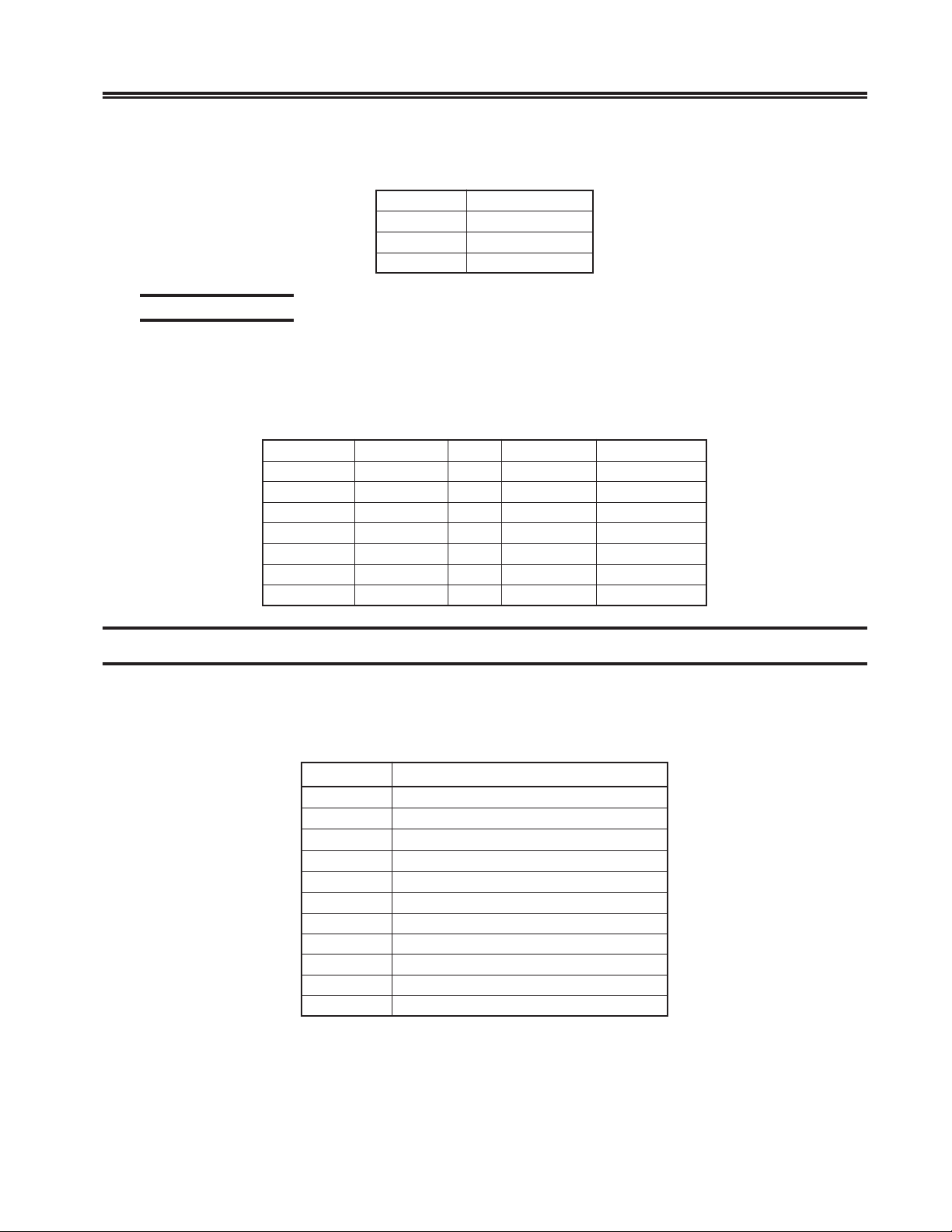
These are optional
slots available with
the EBP-C board.
1 2 3 4 5 6 7 8 9 10 11 12 13
Figure 2-12. Printed Circuit Board Slots, Rear View
2-20 707028-007
Page 31
The following chart presents the physical J number slots used in the JSS member
of failure messages.
Slot Identification
The unit board slots may be identified by either their physical locations (J number)
or their logical identifiers (ID). These numbers are used in identifying boards that
failed. The following is a cross reference list between the board slot J numbers and
the board slot logical IDs.
Chapter 2. Installation
tolSnoitpircseD
31-10stolslenaPkcaB
23ksiddraH
43ksidyppolF
#JDItolS#JDItolS
10D08080
20209090
303001A0
404011B0
505021C0
60603110
7070
Board Slot Population
Board slots 2 - 9 in the 25S/25L/28L/3074 are 32-bit BUS slots capable of supporting
either 16 bit or 32 bit boards. Slots 10 - 13 support 16 bit boards only. The following
chart shows slot restrictions by board type.
draoBstolS
PCS1
PHV9,8,7,6,5,4,3,2
TEF9,8,7,6,5,4,3,2
CSH9,8,7,6,5,4,3,2
CRT9,8,7,6,5,4,3,2
CCS31,21,11,01,9,8,7,6,5,4,3,2
C
CM31,21,11,01,9,8,7,6,5,4,3,2
CSE9,8,7,6,5,4,3,2
*PHC31,11
*CHC21,01
XSE9,8,7,6,5,4,3,2
* CHP and CHC cards should be in adjacent slot pairs of 13,12 or 11,10.
707028-007 2-21
Page 32

Page 33
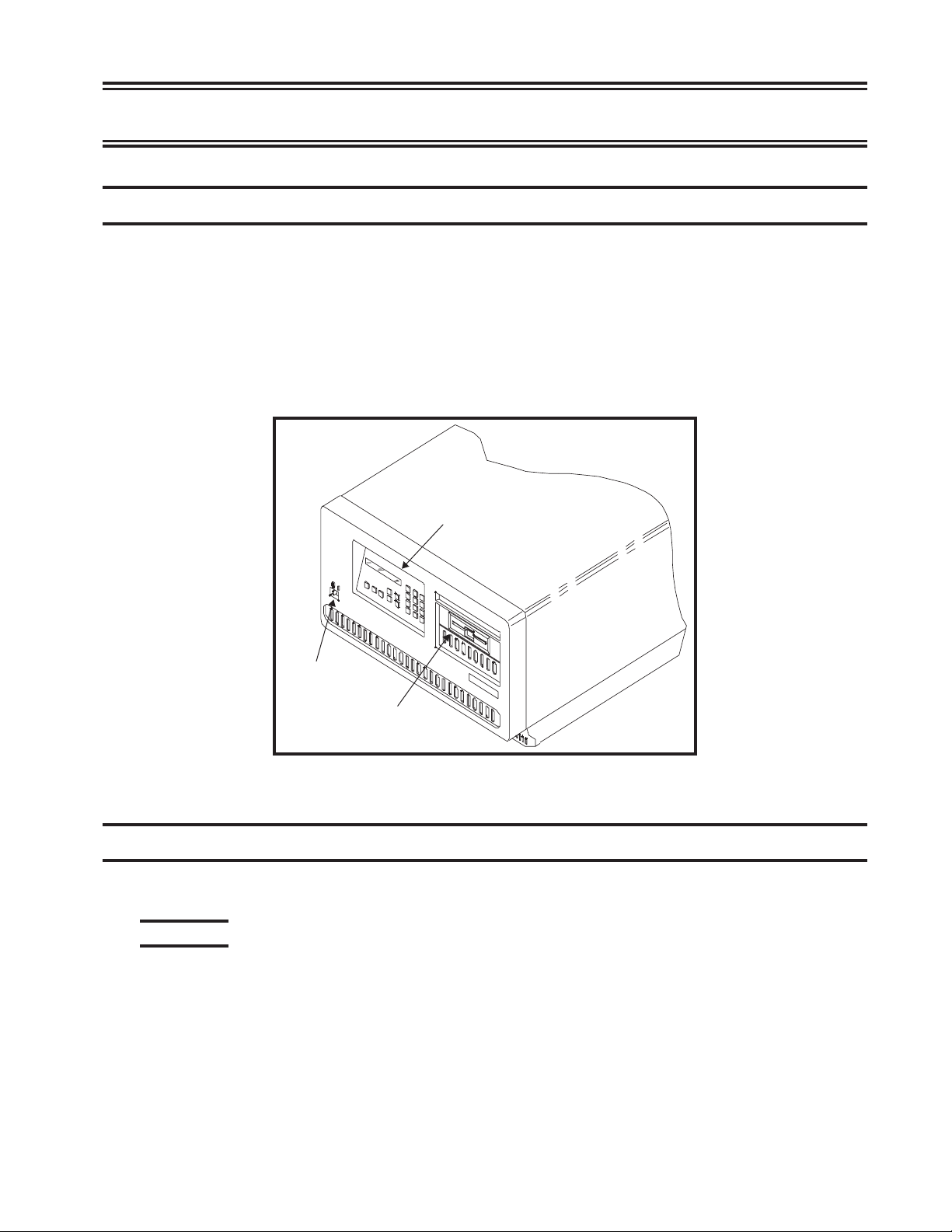
Controls
The power switch is located below the operator panel. Set the switch to the On (|)
position to turn on power, and set the switch to the Off (O) position to turn off
power. See Figure 3-1.
The operator panel is used to enter, select, or change modes of operation.
The 25S/25L/28L/3074 unit contains a hard drive and floppy diskette drive for
data storage.
Chapter 3. Operation
Operator Panel
Power Switch
Operator Panel
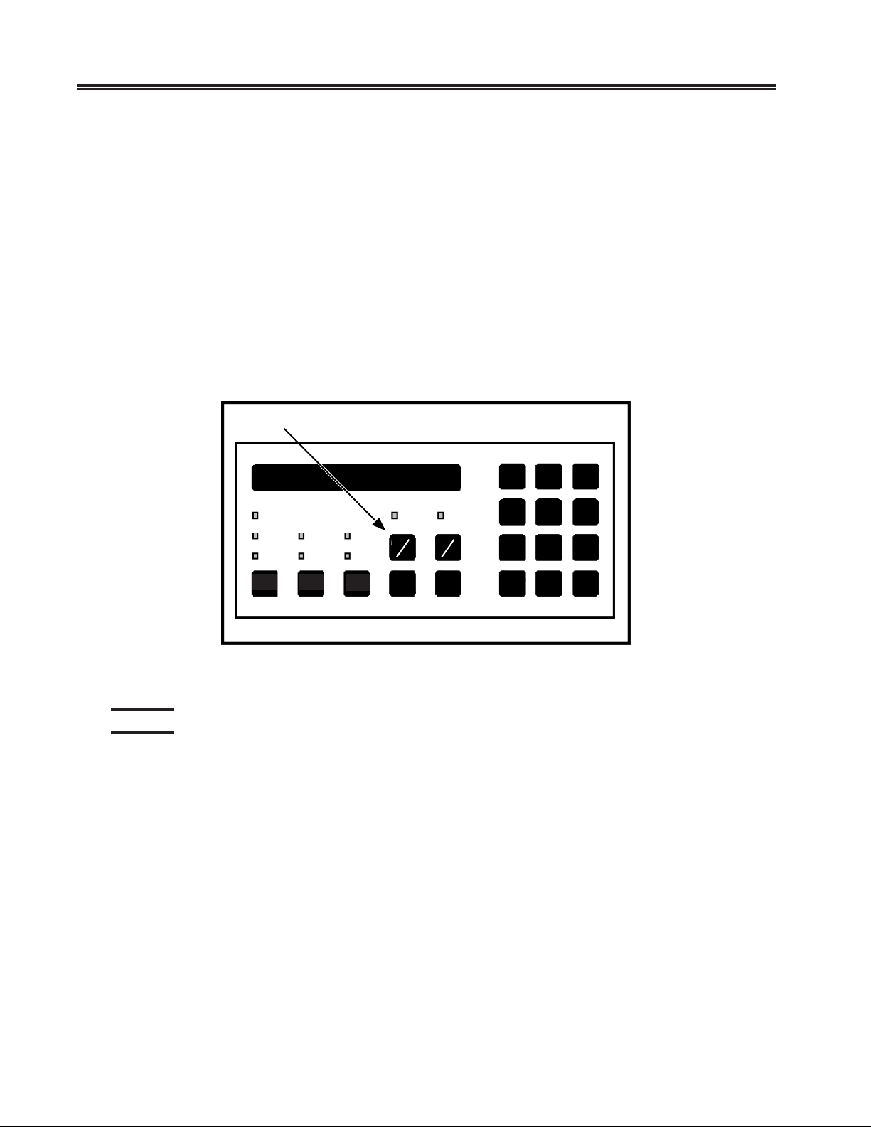
The operator panel is shown in Figure 3-2.
Indicators
Located on the operator panel are an LCD display and LEDs that indicate some of
the operational states of the unit.
Diag - Lights when the controller is in Offline Diagnostics mode. Customer service
representatives use this mode.
Config - Lights when the 25S/25L/28L/3074 is IMLed onto the default
configuration, or if no saved configuration is present. This is the normal condition
for a unit fresh from the factory, booted for the first time.
Flopy Disk Drive
Figure 3-1. 25S/25L/28L/3074 Unit
707028-007 3-1
Page 34
SCON-25L/28L/3074 Console Concentrator
1174-25S Communications Server Hardware Reference Manual
IML - Lights while the controller is executing Basic Assurance tests and loading
its operating program. When the IML light goes off, the operating program is
loaded and the controller is ready for service.
Check - Lights when an error or failure has occurred that requires corrective action.
Power - Lights to indicate that the controller is powered on and that +5 volts are
present.
HD-Act - Lights to indicate hard disk drive activity.
Off-line Indicator - Lights to indicate completion of off-line selection when Channel
Interface selector is set to Off-line.
LCD - Displays operational and diagnostic status messages.
Channel Interface push button switches
Keypad
The following describes the keys and/or key sequences available from the keypad.
Key sequences are separated by commas. When entering a multiple key sequence,
you should press and release each key, one at a time.
Config - When IML 500 appears on the display after the 25S/25L/28L/3074 is
powered on or the <IML> key is pressed, press the <Config> key to IML into the
default configuration only. The Configuration and Central Control Manuals contain
information about the Configuration mode.
Powe r
Check
IML
IML
Channel 1 Channel 2
Offline Offline
HD-Act
Config
Config
Figure 3-2. Operator Panel
Diag
Diag
On
OffOnOff
Adv
Clear
1
2
3
456
789
Enter
0
Alt
Diag - Initiates the diagnostics facility.
Adv - The <Adv> (Advance) key advances the operator panel display while online
or during error conditions.
3-2 707028-007
Page 35

Chapter 3. Operation
Clear - Erases previously entered data, provided that the <Enter> key has not been
pressed. In diagnostic mode pressing the <Clear> key at State 500 of IML initiates
the software merge utility.
Numbers 0 through 9 - Used to enter parameters and perform other data entry
functions.
Enter - Used to enter data. Press the <Enter> key after pressing a string of keys that
represent parameters. When pressed at State 500 of IML, it allows entering of
additional commands.
Alt - Used to initiate basic assurance tests when pressed at IML State 500.
IML - Pressing IML (Initial Machine Load) causes the controller to perform a
complete reload of software from disk. Note that this button has no affect if the
unit is online with the host. To IML a unit that is online, you must first enter the
offline sequence, then you may IML the unit.
The following are valid when IML 500 is displayed. Note that multiple key sequences
may require that you enter the keys prior to actually reaching state 500. Keys
entered while there is information on the LCD, but prior to state 500 will be cached
and read in at state 500.
Adv - Continue IML with System Microcode. No extended BATs are executed. If
an alternate drive and state have been entered (Enter options), then the specified
System Microcode is loaded. Otherwise, the System Microcode in production on
the first hard disk containing a System Disk subdirectory is loaded.
Alt, Adv - Same as Adv, but execute extended BATs during IML.
Diag - Enter Diagnostics mode.
Config - Load default Customization Data Objects instead of those defined on the
System subdirectory allowing the controller to IML with default customization
parameters. With the default configuration loaded, you may enter the Configuration
utility without entering a password.
Alt, Config - Same as Config, but execute extended BATs during IML.
Clear - Clear the System Microcode currently on hard disk and load a new System
Microcode from floppy diskette.
Enter - Provides for additional selection of required input.
707028-007 3-3
Page 36

SCON-25L/28L/3074 Console Concentrator
1174-25S Communications Server Hardware Reference Manual
Channel Interface Selector
When placed in the Online position, the controller is logically connected to the
host channel. When placed in the Off-line position, the controller is disconnected
from the host channel. The Off-line function is not complete until the Off-line
indicator is turned on.
A two-key sequence is required to toggle a channel online/off-line state.
Momentary push-button switches (as shown in Figure 3-2) are used for channel
online/off-line selection. When toggling to the Off-line mode, a status line message
(such as “A: Off-line Pend”) is displayed on the LCD upon recognition of the
key sequence when currently online. Once disconnected from the channel, the
message changes (such as “A: 503-01”).
• For single- and two-channel units, the selected channel button must be pressed,
then the Enter key must be pressed to toggle the state.
• For units with more than two channels installed, press the Channel 1 button,
then the desired channel number (1-8 on the keypad) is pressed to toggle the
channel state.
IML
For Bus and Tag interfaces, the channel online/off-line state is stored in nonvolatile
memory. When the controller is powered off then on, the controller channel online/
off-line state will be that when last powered off. The controller is shipped with
both channels in the off-line state. For ESCON, the channel will always attempt to
go online after power up.
When the 25S/25L/28L/3074 is first powered on or the IML button is pressed (and
the unit is offline) an IML occurs. The LCD on the operator panel displays messages
indicating the progress of the IML.
The “mode prompt” appears on the LCD at state 500: IML 500 M=
At this state, the LINCS node will pause for five seconds waiting for input
from the operator keypad illustrated below. If nothing is specified within five
seconds, the standard IML will proceed.
• 1 – Boots from trial (merge) directory.
• 2 – Boots from system (production) directory - default.
• 3 – Boots from backup directory.
• ADV – Continue IML with system microcode. No extended BATs are executed.
• ALT, ADV – Same as ADV, but executes extended BATs during IML.
• DIAG – Enters Diagnostics mode.
• CONFIG – Loads default customization data objects instead of the ones defined
in the system subdirectory. This option is useful when a problem with the
customization data affects the operation of the LINCS node. This option allows
3-4 707028-007
Page 37
Chapter 3. Operation
IML with default customization parameters without affecting the ones defined
in the system subdirectory. Loading the default configuration also allows you
to enter the Configuration utility without entering a password. Once the default
customization data objects have been loaded and the LINCS node has IMLed,
the data objects may be modified as desired.
• ALT, CONFIG – Same as CONFIG, but executes extended BATs during IML.
• ENTER – Prompts will be displayed for entry of drive from which to IML,
level of software, and mode of operation for IML state.
Note: This only applies when Central Site Change Management is being used!
Central Site Change Management requires downloading the back level and trial
levels from a host application such as Netview Distribution Manager.
The following describes the parameter entries allowed.
retemaraPnoitpircseD
d
Selects Central Site Change Management software (level
or state from which to IML>
noitcudorP-1
l
m
levelkcaB-2
lairT-3
.desugniebsi
LMIothcihwmorfevirdksidstceleS
artneCnehwseilppaylnosihT
.LMIrofnoitarepofoedoMstceleS
)TABgnissapybLMIlamron(lamroN=vdA
edomnoitarugifnoCotniLMI(gifnoC=gifnoC
tnemeganaMegnahCetiSl
)
1. The first prompt displayed is IML 500 D=_. Enter the drive to be used for
IML.
2. The second prompt is IML 500 L=_. Enter the software level.
3. The third prompt is IML 50X M=_, where X is the drive selected. Enter the
type of IML mode.
4. Allow IML to complete.
Please refer to Visara’s LINCS Problem Determination Manual for an explanation
of LINCS messages.
Error Types
This section describes the types of errors and failures that can occur while the unit
is operating. Details of error codes and their interpretation can be found in the
LINCS Problem Determination Manual.
The main types of errors or failures are IML errors, exception errors, hardware
failures, and online errors.
Indicators showing an error condition has occurred include:
• Online Error log (Central Control Mode utility 7/3).
• Status line of attached terminal.
707028-007 3-5
Page 38

SCON-25L/28L/3074 Console Concentrator
1174-25S Communications Server Hardware Reference Manual
• Operator panel LCD.
• Operator panel check light.
• Printed circuit board LEDs.
• Box$fail.txt file in system directory of hard drive.
IML Errors (ERR___)
Initial Machine Load (IML) occurs when the unit is turned on, or when the IML
key on the operator panel is pressed. During IML, the unit executes a series of tests
that checks the machine’s ability to operate.
An IML error message displays as ERR XXX* on the operator panel, where
ERR indicates the occurrence of an IML error.
XXX is the IML state in which the error occurred.
* indicates that additional messages are available that describe the error (not always
present).
IML errors and possible recovery are described in the LINCS Problem Determination
Manual, “IML States and Errors.”
IML errors are logged into the box$fail.txt file.
Exception Errors (XCP___)
Exception errors are detected by a processor and occur during IML. Exception
errors are nonrecoverable and require recording the error information and then
IMLing the unit to resume operation.
Exception error messages look like this on the operator panel:
XCP JSS:BB:EEE*
where:
XCP indicates an exception error.
JSS indicates the physical slot number of the board where the error occurred or
was identified.
BB shows the board ID in hexadecimal format.
EEE shows the type of exception error.
* indicates additional messages that give more information about the error (not
always present).
The LINCS Problem Determination Manual contains additional information about
exception errors.
3-6 707028-007
Page 39
If unable to correct the problem, prepare a dump disk of the error information (see
the LINCS problem Determination Manual) and then call the next level of technical
support.
Exception errors are recorded into the box$fail.txt file.
Hardware Failures (FAIL___)
Hardware failures show specific hardware problems. They may occur during IML
or testing mode. Code verification errors may also display as a hardware failure.
Error messages display on the operator panel as shown below:
Hardware - FAIL JSS:BB:TNN*
Code Verification - FAIL JSS:BB:MOV*
where:
FAIL indicates a hardware error.
JSS is the slot number of the failing board.
BB shows the board type ID in hexadecimal format.
T is the failing test type.
NN is the failing test number.
MOV indicates that the diagnostic code a processor board moved to its local memory
does not match the code from where it was moved.
* indicates additional messages that give more information about the error.
Chapter 3. Operation
The LINCS Problem Determination Manual contains additional information about
hardware failures.
Online Errors
Online errors show problems that occur while the unit is online with its host and
attached devices. Online error numbers may appear on the operator panel (some
300- and 500-type errors only), preceded by an indication of which attached host
system is involved, and may be displayed on an attached display’s status line
preceded by X. The LINCS Problem Determination Manual describes Online errors
and recovery procedures.
Online errors are recorded into the Central Control Mode Event Log (utility 7/1).
Error Indicators
Event Log
The unit’s Event Log records the Online events and errors described in the LINCS
Problem Determination Manual. See the LINCS Problem Determination Manual or
the LINCS Central Control Manual for information on how to display the Event
Log.
707028-007 3-7
Page 40

SCON-25L/28L/3074 Console Concentrator
1174-25S Communications Server Hardware Reference Manual
Status Line of Attached Terminal
The status line of attached terminals shows many of the Online errors and conditions
that occur. These errors are normally recorded in the Event Log. The LINCS Problem
Determination Manual contains additional information about Online errors.
Operator Panel Display
The 16-character operator panel LCD display indicates a wide variety of states and
errors. The operator panel LCD display shows all error conditions except errors
occurring in IML before the operator panel is initialized and certain online errors.
Software Merge
This procedure is required for software upgrading and initial installation of software
on the 25S/25L/28L/3074. See the LINCS Problem Determination Manual for
additional information.
1. If you currently have a functioning unit, it is recommended that you back up
your unit prior to proceeding through the merge process. You can back up the
software to floppy using Media Management in Central Control Mode (utility
3/2), approximately 40 minute procedure. You can back up the current contents
of the System Directory by copying the contents to a backup directory by
using the Central Control Mode utility 3/7, approximately 3 minute procedure.
2. IML the unit.
3. At “IML 500 M=” press the <Clear> key.
Note: To abort the merge procedure before continuing, press the IML key. The
merge procedure will overwrite existing microcode files of the same name,
so it is not recommended to abort the procedure once the merge has started.
4. At the “Merge a: to c:” prompt, press the Enter key to proceed with the software
merge.
5. At the “Insert a:SYSn” prompt, insert the requested system diskette (by number
n) in the source drive, close the drive door, then press the Enter key. A progress
message “nn% Complete” is displayed while files are being copied.
6. At the “Merge Complete” message, press the IML key to initiate the IML
process to boot on the new code.
Warning and failure messages may be displayed indicating problems during the
merge. If the merge process fails, check the disk media and if it appears to be ok
(you can view the file list on a PC), attempt the merge process again, from the
beginning. If you are unable to successfully complete the merge process, and you
backed up the current code into the backup directory (described in step 1), you
may boot onto the backup directory by pressing the <3> key at IML state 500.
3-8 707028-007
Page 41
Chapter 3. Operation
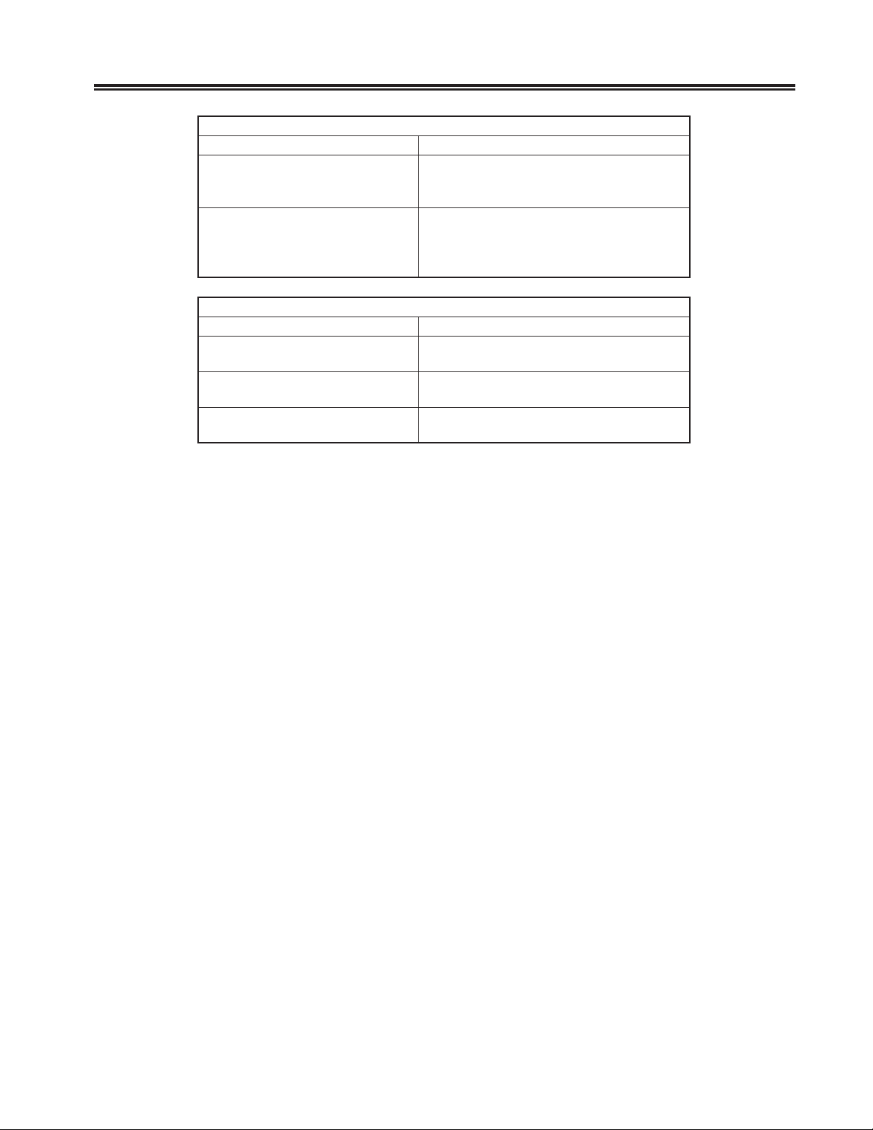
segasseMgninraW
egasseMnoitpircseD
sievirdecruosehtotnidetresnietteksidehT
ksiDgnorW
leveLgnorW
segasseMeruliaF
egasseMnoitpircseD
yppolFLIAF
draHLIAF
ee:xksiDLIAF
.ecruos
.noitanitsed
.)eulav
Note: The floppy disks used for the merge routine must have the appropriate
volume labels to be read by LINCS. These are:
sysdetseuqerehtton
.egassemksidtresni
rahaseriuqeregremehT
retnEehtsserP.ksidmet
.egassemksidtresniehtotnruterotyek
sievirdecruosehtotnidetresnietteksidehT
metsyssuoiverpehtsalevelemasehtfoton
ehtotnruterotyekretnEehtsserP.setteksid
ehtsaevirdyppolfaseriuqeregremehT
ehtsaevirdd
rorre=ee,evird=x(rorreksidasawerehT
System 1 - @@D@@@@@174
System 2 - @@H@@@@@174
System 3 - @@@A@@@@174
System 4 - @@@B@@@@174
707028-007 3-9
Page 42

Page 43
Chapter 4. Assembly Removal/
Introduction
All members of the 25S/25L/28L/3074 family utilize the same chassis. The following
procedures describe removal/replacement of assemblies that may be installed in
the 25S/25L/28L/3074 unit.
Prior to any removal or replacement procedure, make sure the unit is turned OFF
and the power cord is disconnected from the AC wall outlet.
Due to electrical hazard, do not remove the system cover. Only qualified service
personnel may remove the system cover for service or installation of circuit
cards.
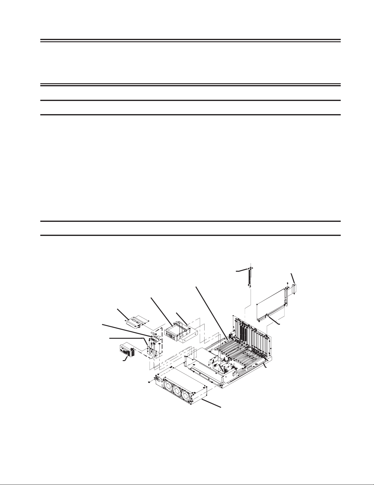
Assembly Drawing
Replacement
WARNING
Diskette Holder
OPBA PCB
OP MTG BKT
Operator Panel
3.5” FDD
EBP-C PCB
Hard Drive
Slot Cover
Power Supply
Male SCSI Term
SCP PCB
Backpanel PCB
707028-007 4-1
Page 44
SCON-25L/28L/3074 Console Concentrator
1174-25S Communications Server Hardware Reference Manual
Field Replaceable Assemblies
noitpircseDmssAnoN/PN/PURFL52L82S524703setoN
lenaPkcaB100-152022100-152022seYseYseYseY
lenaPkcaBnoisnapxE100-062022100
)rossecorPlortnoCmetsyS(PCS
S52-4711-BCP009-352022009-352022seYseYseYseY
L52-BCP333-352022333-35
L82-BCP444-352022444-352022oNseYoNoN
4703-BCP555-352022555-352022oNoNoNseY
)rossecorPdeepShgiH.V(PHV
BCP
BCP)NOCSE(CSE
BCP)dednetxENOCSE(XSE469-27
BCP)dednetxENOCSE(XSE469-272022100-014779oNoNoNseY
BCP)tenrehtEspbM001/01(TEF909-372022900-3
BCP)gniRnekoT61/4(IICRT909-716602900-500659seYseYseYoN
)ecafretnIgaT&suB(C-CTB009-824312009-82431
BCP)rellortnoClennahC(CHC909-316602909-316602oNoNseYoN
BCP)rossecorPlennahC(PHC909-216602909-216602oNoNseYoN
xaoCdexelpitluM(CCM
BCP)rellortnoC
snoitacinummoClaireS(CCS
BCP)rellortnoC
laireSdeepShgiH(CSH
BCP)snoitacinummoC
)53.V,232SR(1MILP100-707869100-707869oNoNseYoN
)12.X(2MILP100-807869100-807869oNoNseYoN
)elbaCretpadACSH(CAH100-012022100-012022oNoNseYoN
elbaCrewoPevirD200-302022200-302022seYseYseYseY
CDsselhsurB,naF200-906122200-906122seYseYseYseY
"52.5ni,kcalb"5.3,evirDyppolF
elbac,tekcarb
evirDdraHISCS954-14082oNoNseYoN3
elbaClangiSDDH100-402022100-402022seYseYseYseY
EDIotISCShtiwevirDdraHEDI
retpadaegdirb
on(BG04,evirDdraHEDI
)retpada
)retpadaEDIotISCS(drac'a'200-83635200-83635seYseYseYseY
rotalsnartlenaPpO(ABPO
BCP)retpadA
lenaPpO400-007112400-007112seYseYseYseY
elbaClenaPpO100-202022100-202022seYseYseYseY
FhtiwylbmessAylppuSrewoP100-024122100-024122seYseYseYseY
sna
gnisaCtuohtiwylppuSrewoP100-74435100-74435seYseYseYseY
BCP
CCSrofelbaC232SR
-172022909-172022seYseYseYseY
909
909-272022
719-272022
2022614-272769oNseYoNoN
2oNoNseYoN
100-606602900-110659seYseYseYoN
909-555012900-773359oNoNseYoN
909-562022900-562769oNoNseYoN
001-533122001-533122seYseYseYseY
040-93635040-93635seYseYseYseY
100-462122100-462122seYseYseYseY
020-821112
040-821112
-062022seYseYseYseY
2022seYoNoNoN
900-272769seYoNseYoN2,1
72769seYseYseYseY
100-147598seYseYseYseY
020-066659
040-066659
oNoNseYoN
4-2 707028-007
Page 45
Chapter 4. Assembly Removal/Replacement
Field Replaceable Assemblies cont’d
noitpircseDmssAnoN/PN/PURFL52L82S524703setoN
BCPCCSrofelbaC53.V100-031112100-166659oNoNseYoN
BCPCSHrofelbaC232SRETD02
BCPCSHrofelbaC232SRECD020-217869020-217869oNoNseYoN
BCPCSHrofelbaC53.VETD020-317869020-3
BCPCSHrofelbaC53.VECD020-417869020-417869oNoNseYoN
BCPCSHrofelbaC12.XETD020-517869020-517869oNoNseYoN
PNOCSE100-35535100-35535seYseYseYseY
gul
:setoN
.mroftalpehtnodellatsniebrehgih
alper
0-117869020-117869oNoNseYoN
17869oNoNseYoN
Removal/Replacement Procedures
ro2.8SCNILseriuqertub909-272022BCPCSEecalpernac719-272022BCPCSE.1
ehtnodracCSElanoitiddanallatsniotdesuebtonnac900-272769URFCSE.2
sRAPLlanoitiddarofnoitavitcaerutaefseriuqeroslaL52-NOCSehT.L52-NOCS
.troppu
erasevirDdraHISCS,S52-4711ehtnoyllanigirodeppihsylnoevirDdraHISCSehT.3
.)001-533122N/P(egdirbEDIotISCSehthtiwevirdEDIwenagnillatsniybdec
Main Cover
Removal
1. Ensure power is off.
2. Remove the six screws attaching the main cover to the unit chassis.
3. Slide the main cover toward the front of the unit and lift clear to remove it
from the chassis.
Replacement
Reverse the procedure to replace the cover. Be careful when moving the main
cover towards the rear, so as not to snag any of the cables. Proper alignment of the
main cover before pushing it into place is very important to avoid damaging the
hardware. Pay particular attention to the position of the On/Off switch and the
floppy disk drive with regards to their openings in the cover. When the main cover
is in the correct position, the rear cover should make direct contact with it. (If it
appears that you can not reinstall the screws without distorting the rear cover, then
the main cover is not correctly positioned.)
707028-007 4-3
Page 46

SCON-25L/28L/3074 Console Concentrator
1174-25S Communications Server Hardware Reference Manual
Circuit Board Assembly
Removal
1. Ensure power is off. Remove the main cover.
2. Locate the Circuit board to be removed.
3. Disconnect all cables attached to the Circuit board.
4. Remove the screw securing the board to the rear entry panel.
5. Lift the board from its back panel connector and slide it clear of the unit.
Replacement
1. Install the new card by carefully inserting it into the slot vacated in removal
step 5.
2. Use the screw removed in step 4 above to secure the newly installed board.
3. Use the Main Cover Replacement procedure described above.
Note: Replacement of the SCP Card should be by authorized support personnel
only. The transfer of licensing information is required to make the board
work properly.
Operator Panel
Removal
1. Ensure power is off. Remove the cover.
2. Remove the operator panel by carefully pushing out on one of the tabs on
either side of the panel housing. These tabs are very fragile.
3. Lift the panel clear of the operator panel mounting bracket.
4. Disconnect the operator panel cable.
Replacement
1. Move the new operator panel into position, lining the tabs of the panel to the
proper position in the mounting bracket. Very carefully press the panel into
place. The mounting tabs are very fragile, and will easily break off if stressed.
2. Plug the operator cable into the corresponding socket, paying attention to the
cable orientation and key.
3. Use the Main Cover Replacement procedure described above.
4-4 707028-007
Page 47

Floppy Disk Drive
Removal
1. Ensure power is off. Remove the cover.
2. Locate and disconnect the drive signal and power supply cables.
3. Remove the four screws attaching the disk drive to its bracket. There are two
screws located on each side of the drive bracket.
4. Carefully slide the drive from its bracket.
Replacement
1. Align the disk drive into its mounting track.
2. Carefully slide the disk drive into its bracket.
3. Install the screws to attach the drive to the bracket.
4. Connect the drive signal and power supply cables.
Chapter 4. Assembly Removal/Replacement
5. Replace the cover carefully, using the Main Cover Replacement procedure
described above. You may have to reposition the disk drive to align it with the
cover properly.
Hard Disk Drive
The hard disk drive is installed below the floppy drive. Note that older platforms
use a SCSI hard disk, while newer platforms use an IDE hard disk with a SCSI to
IDE adapter mounted to it.
Removal
1. Ensure power is off. Remove the cover.
2. Remove the floppy disk drive assembly.
3. Remove the SCP and any other boards required to provide space for hard disk
drive removal from the unit.
4. Locate and disconnect the hard disk drive signal, fan and power supply cables.
5. Remove the four screws attaching the hard disk drive to its bracket. There are
two screws located on each side of the drive bracket.
6. Carefully slide the drive from its bracket.
707028-007 4-5
Page 48

SCON-25L/28L/3074 Console Concentrator
1174-25S Communications Server Hardware Reference Manual
Replacement
1. Align the disk drive into its mounting track.
2. Carefully slide the disk drive into its bracket.
3. Install the screws to attach the drive to the bracket.
4. Connect the drive signal and power supply cables.
Note: Ensure the drive signal cable is properly attached to the back panel connector.
5. Reinstall any boards and floppy disk drive that were removed.
6. Replace the cover using the Main Cover Replacement procedure described
above.
7. If the replacement drive does not have LINCS software on it already, you may
have to format the drive (Offline Utility 41), then initialize the drive (Offline
Utility 36), then perform a software merge of LINCS code. Information on
how to run the Offline Utilities can be found in the LINCS Problem
Determination Manual. Merging new code onto the drive can be found in
Chapter 3 of this manual.
Power Supply Assembly
Removal
1. Ensure power is off and disconnect AC power. Remove the cover.
2. Disconnect the fan cables from the back panel. Please note that there are three
separate connector locations!
3. Disconnect the AC input from the connector on the back of the power supply.
4. Remove the two screws attaching the power supply assembly to the chassis.
5. Slide the assembly from its mounting.
Replacement
1. Slide the new power supply assembly into position and secure with screws.
2. Reconnect the AC input and fan cables.
3. Reinstall the cover using the Main Cover replacement procedure described
above.
4. Reattach the AC power and boot.
4-6 707028-007
Page 49

Chapter 4. Assembly Removal/Replacement
Back Panel and Expansion Back Panel Assembly
Removal
1. Ensure power is off and disconnect AC power.
2. Disconnect the cables attached to boards.
3. Remove the cover.
4. Remove all Circuit boards attached to the back panel and expansion back
panel from the unit, using standard antistatic handling precautions.
5. Disconnect all cables attached to the back panel.
6. Disconnect fan cables from the power supply.
7. Disconnect the power supply assembly from the back panel.
8. Disconnect the power supply AC cable.
9. Remove the ten screws attaching the back panel, and the six screws attaching
the expansion back panel to the chassis.
10. Carefully lift the back panel and expansion back panel from the chassis.
11. Separate the two back panels after removal from the chassis.
Replacement
1. Marry the back panel and expansion back panel, and install them into the
chassis cavity by reinstalling the screws of step 9, taking care to line up the
DC power connector of the power supply when putting the cards into position.
2. Reattach the power supply AC cable, fan cables, drive cables, etc.
3. Reinstall the circuit boards removed in step 4 above, and secure them with
screws.
4. Reinstall the cover using the Main Cover replacement procedure above.
5. Reinstall cables including power cable and apply power.
New Hardware Installation Procedures
The installation of new hardware features onto the 25S/25L/28L/3074 is very similar
to the replacement of existing hardware with a few notable exceptions. First, you
will be removing and discarding existing plates and brackets, and substituting
feature boards in their place. Secondly, you will need to know where to place the
new board, since the existing 25S/25L/28L/3074 does not already have one installed.
Positioning of the new hardware requires knowledge of how the 25S/25L/28L/3074
will react by numbering the cards. Finally, you will probably need to inform the
software that the new hardware has been installed.
707028-007 4-7
Page 50

SCON-25L/28L/3074 Console Concentrator
1174-25S Communications Server Hardware Reference Manual
Selecting Location for the New Board
In general, the 25S/25L/28L/3074 will number the cards of a specific type going
from lowest Slot ID to the largest Slot ID. Note that the Slot Number and the Slot
ID are not the same in all cases. Specifically Slot 13 and Slot 1 have their Slot IDs
swapped. You can avoid confusion by not using Slot 13 unless you have to.
If you must locate a new board of a type already installed, it is best if you can
install the new board in a slot with a higher Slot ID than the others. If this can not
be done, you may have to move the cabling associated with this board type, from
one board to another to keep the numbering straight.
Board Installation Procedure
1. Follow the procedures for removing the covers from the 25S/25L/28L/3074.
2. Using the Board Slot Population chart as a guide, select the slot where you
intend to locate the new board.
3. Locate the screw holding the bracket in place for the slot where you want to
position the new board. Remove the screw.
4. Position the new board into the slot associated with the bracket that you just
removed, and carefully plug it in.
5. Using the screw removed in step 2, secure the board bracket to the rear bracket.
6. Reassemble the covers.
7. Plug any cables associated with the new board, into the appropriate connectors.
8. Using the appropriate Configuration Manual as a guide, boot the 25S/25L/
28L/3074 and adjust the values shown on the Product Definition panel in
configuration to reflect the new hardware that was just installed.
4-8 707028-007
Page 51

Index
Symbols
1174-25S General Description 1-1
3270 Coax Cables 2-5
3270 Host Connection 2-8
A
Assembly Drawing 4-1
Attaching the ESC Interface to the Channel 2-18
B
Back Panel & Expansion Back Panel Assembly
Removal 4-7
BTC-C 1-3
Bus/Tag Cable Interfacing 2-14
C
Cable Distances 2-5
Cables 2-11
Channel Board Installation 2-14
Channel Cables 2-5
Channel Interface Selector 3-4
CHC/CHP 1-3
Circuit Board Removal 4-4
Coax Terminal Server 1-2
Communications Concentrator 1-2
Connecting to the Channel 2-11
Controls 3-1
E
EIA - RS232
(for HSC) 2-5
(for SCC) 2-5
Environmental Parameters 2-4
Error Types 3-5
ESC 1-3
ESCON Channel Interface 2-17
ESX 1-3
Ethernet Cable 2-5
Ethernet Connection 2-8
Event Log 3-7
Exception Errors 3-6
G
General Description 1-1
1174-25S 1-1
SCON-25L 1-1
SCON-28L 1-1
H
Hard Disk Drive Removal 4-5
Hardware Components 1-3
Hardware Failures 3-7
Hardware Installation Procedures 4-7
High Speed Communication Interface 2-19
HSC 1-3
I
IML 3-4
IML Errors 3-6
Indicators 3-1
Installing/Removing Printed Circuit Boards 2-3
IP Channel Bridge 1-2
K
Keypad 3-2
L
LAN Device Support 1-2
LAN Printer Support 1-2
LED Descriptions 2-10
Local Channel Bypass 2-16
Location Planning 2-4
M
Main Cover Removal 4-3
MCC 1-3
Memory Requirements 2-2
O
Online Errors 3-7
Operator Panel Display 3-8
Operator Panel Removal 4-4
F
FET 1-3
Field Replaceable Assemblies 4-2, 4-3
Floppy Disk Drive Removal 4-5
707028-007 Index-1
P
Power Cable 2-5
Power Cable Requirements 2-7
Power Requirements 2-4
Power Supply Assembly Removal 4-6
Page 52

SCON-25L/28L/3074 Console Concentrator
1174-25S Communications Server Hardware Reference Manual
R
RS232 Serial Interface 2-18
S
SCC 1-3
SCON-25L General Description 1-1
SCON-28L General Description 1-1
Serial Port 2-18
Setting the Priority on the BTC 2-15
Slot Identification 2-21
Software Merge 3-8
Switches/Indicators 2-10
T
TN3270E Server 1-2
Token Ring Cable 2-5
Token Ring Connection 2-8
TRC 1-3
U
Unpacking Printed Circuit Boards 2-3
V
V.35 Cable
(for HSC) 2-5
(for SCC) 2-5
VHP 1-3
Index-2 707028-007
 Loading...