

Visara SCON-20L Installation

SCON-20L/22L/25L/28L/3074 Console Concentrator
Planning and Installation Guide
P/N 707054-005

ELUDEHCSNOISIVER/EUSSI
stnemmoC.oN.veRetaD
esaeleRlaitinI100-45070710/41/3
etadpU200-45070720/50/9
etadpU300-45070750/60/1
noitcerroC400-45070750/91/9
dda4703-NOCS500-45070760/21/5
noiti
ii 707054-005

Read This First
This is the SCON-20L/22L/25L/28L/3074 Planning and Installation Guide.
Information on the LINCS Operating System can be ordered separately.
Please visit our website, www .visara.com, to access all manuals online.
1.From your Internet br owser type http://www.visara.com
2.Select Support
3.Select Product Manuals
4.Select one of the following:
•
SCON-20L/22L/25L/28L/3074 Planning and Installation Guide
•
SCON-20L/22L Hardware Reference Manual
•
SCON-25L/28L/3074/1174-25S Hardware Reference Manual
•
SCON-20L/22L/25L/28L/3074 Configuration Manual
•
LINCS Features
•
LINCS Problem Determination
•
LINCS Configuration
•
LINCS Central Control
707054-005 iii

Product Safety
The SCON-2XL/3074 Console Concentrator complies with relevant product safety standards, such as the
UL and CSA, and TUV-GS Rules and Regulations.
FCC and CDC Regulatory Statements
This equipment has been tested and found to comply with the limits for a Class A computing device,
pursuant to Part 15 of the FCC Rules. These limits are designed to provide reasonable protection against
harmful interference in a commercial installation. This equipment generates, uses, and can radiate radio
frequency energy and, if not installed and used in accordance with the instructions, may cause harmful
interference to radio communications. However, there is no guarantee that interference will not occur in a
particular installation. If this equipment does cause harmful interference to radio or television reception,
which can be determined by turning the equipment off and on, the user is encouraged to try to correct the
interference by using one or more of the following measures:
• Reorient or relocate the receiving antenna.
• Increase the separation between the equipment and the receiver.
• Connect the equipment into an outlet on a circuit different from that to which the receiver is connected.
• Consult the dealer or an experienced radio/TV technician for help.
This equipment has been certified to comply with the limits for a Class A computing device, pursuant to
FCC Rules. In order to maintain compliance with FCC regulations, shielded cable must be used with this
equipment. Operation with nonapproved equipment or unshielded cables is likely to result in interference
to radio and TV reception. The user is cautioned that changes and modifications made to the equipment
without the approval of the manufacturer could void the user’s authority to operate this equipment. The user
may find the following booklet prepared by the Federal Communications Commission helpful:
How to Identify and Resolve Radio-TV Interference Problems
This booklet is available from the U.S. Government Printing Office, Washington DC 20402, Stock No.
004-000-00345-4.
This digital apparatus does not exceed the Class A limits for radio noise emissions from digital apparatus
set out in the Radio Interference Regulations of the Canadian Department of Communications.
Le présent appereil numérique n’émet pas de bruits radioélectriques dépassant les limites applicables aux
appareils numériques de la classe A prescrites dans le Règlement sur le brouillage radioélectrique édicté
par le ministère des Communications du Canada.
iv 707054-005

Table of Contents
Page
Read This First ......................................................................................................... iii
Product Safety ...........................................................................................................iv
FCC and CDC Regulatory Statements ......................................................................iv
Chapter 1. Overview ........................................................................................................ 1-1
Environmental Parameters...................................................................................... 1-2
Power Requirements............................................................................................... 1-2
Chapter 2. Planning for Your Install ................................................................................. 2-1
Identifying the Environment .................................................................................. 2-1
Replacing Existing ESCON 3174 Controllers ....................................................... 2-1
Replacing Existing 2074 Controllers ..................................................................... 2-2
Replacing Bus and Tag Controllers ........................................................................ 2-2
Determining the Need for ESCON Directors......................................................... 2-2
When to Use EMIF ................................................................................................ 2-2
StorageT ek LMUs Planning................................................................................... 2-2
FICON Usage ......................................................................................................... 2-2
IBM 3290 Plasma Display Planning ...................................................................... 2-2
Planning for the Visara UCT-L............................................................................... 2-3
Planning for Hot Console Sessions ........................................................................ 2-3
Use of ESCON Channel Extenders ........................................................................ 2-3
Secure Network Connections ................................................................................. 2-4
Management Planning............................................................................................ 2-4
Planning for eManager Support ............................................................................. 2-5
SCON Maximum Capability Chart ........................................................................ 2-6
Determining the number of SCON......................................................................... 2-7
Parameter Definition Cross Reference Chart ......................................................... 2-8
Chapter 3. Configuring the SCON ................................................................................... 3-1
Configuring the Host Interface............................................................................... 3-1
SCON Line Options/ESC Panel - (Non-SNA with Channel P ath Filter)........... 3-2
SCON Line Options/ESC Panel - (Non-SNA)................................................... 3-3
SCON-3270 Host Circuit Panel ......................................................................... 3-4
Configuring for Traditional Coax Displays
(does not apply to SCON-3074)............................................................................. 3-4
Device Options/General Panel ........................................................................... 3-5
SCON Device Profile Panel............................................................................... 3-6
SCON Device Profile Assignments Panel.......................................................... 3-7
Special Considerations for StorageT ek LMUs....................................................... 3-8
Enabling PC File Transfer for StorageTek LMU ............................................... 3-8
Enabling Coax Poll Rate for StorageTek LMU ................................................. 3-8
Configuring for Hot Console Sessions................................................................... 3-9
Configuring for Telnet Clients (does not apply to SCON-3074).......................... 3-10
Line Options Panel - FET Card ....................................................................... 3-10
Line Options - TCP/IP Options........................................................................ 3-11
Network Device Definition Panel - Telnet Client Definition ........................... 3-11
Network Device Definition Panel - Telnet Client Definition ........................... 3-12
Device Options/General Panel ......................................................................... 3-12
Device Profile - ASCII Display Options .......................................................... 3-13
Device Profile Assignments - Telnet Clients.................................................... 3-13
707054-005 v

SCON-20L/22L/25L/28L/3074 Planning and Installation Guide
Configuring for TN3270E Clients........................................................................ 3-14
Line Options - FET .......................................................................................... 3-14
Line Options Panel - TCP/IP Options.............................................................. 3-15
TCP/IP Options Panel ...................................................................................... 3-16
3270 Host Classes Panel .................................................................................. 3-17
TN3270 Client Definition Panel ...................................................................... 3-18
Device Options/General Panel ......................................................................... 3-19
Configuring for LAN Printers (does not apply to SCON-3074) .......................... 3-20
Line Options Panel - FET ................................................................................ 3-20
Line Options - TCP/IP Options Panel.............................................................. 3-21
TCP/IP Options Panel ...................................................................................... 3-22
Network Device Definition Panel - LPD Printer ............................................. 3-23
Network Device Definition Panel - TCP Printer.............................................. 3-24
Device Profile Assignments Panel - Printer ..................................................... 3-25
Device Profile - Printer, Second Panel............................................................. 3-25
Device Profile Assignments - LAN Printers .................................................... 3-26
Configuring for Remote Management ................................................................. 3-26
Configuring for T elnet or TN3270 Host Sessions ................................................ 3-28
Line Options Panel - FET ................................................................................ 3-28
Line Options - TCP/IP Options Panel.............................................................. 3-28
ASCII Session Profile ...................................................................................... 3-29
ASCII Session Profile - Telnet Options (Configured for a Telnet Session)..... 3-30
ASCII Session Profile - Telnet Options (Configured for a TN3270 Session).. 3-30
IP Host Classes Panel....................................................................................... 3-31
Device Profile Panel - Display (Conf igured for Telnet/TN3270 Host Access) 3-32
Device Profile Assignments Panel ................................................................... 3-33
Back Up Your Configuration ................................................................................ 3-33
Backup Using Copy Data Object Utility.......................................................... 3-33
Backup Using FTP Interface............................................................................ 3-34
Backup Using eManager.................................................................................. 3-35
Page
Chapter 4. Cabling Diagram for the SCON .................................................................... 4-1
Chapter 5. Host Gens - OS/390 with HCD ...................................................................... 5-1
Task List ................................................................................................................. 5-1
HCD Panel 1 ...................................................................................................... 5-1
HCD Panel 2 ...................................................................................................... 5-2
HCD Panel 3 ...................................................................................................... 5-2
HCD Panel 4 ...................................................................................................... 5-3
HCD Panel 5 ...................................................................................................... 5-3
HCD Panel 6 ...................................................................................................... 5-4
HCD Panel 7 ...................................................................................................... 5-4
HCD Panel 8 ...................................................................................................... 5-5
HCD Panel 9 ...................................................................................................... 5-5
HCD Panel 10 .................................................................................................... 5-6
HCD Panel 11 .................................................................................................... 5-6
HCD Panel 12 .................................................................................................... 5-7
HCD Panel 13 .................................................................................................... 5-7
HCD Panel 14 .................................................................................................... 5-8
vi 707054-005

Table of Contents
Page
HCD Panel 15 .................................................................................................... 5-9
HCD Panel 16 .................................................................................................... 5-9
HCD Panel 17 .................................................................................................. 5-10
HCD Panel 18 .................................................................................................. 5-10
HCD Panel 19 .................................................................................................. 5-11
HCD Panel 20 .................................................................................................. 5-11
HCD Panel 21 .................................................................................................. 5-12
HCD Panel 22 .................................................................................................. 5-12
HCD Panel 23 .................................................................................................. 5-13
HCD Panel 24 .................................................................................................. 5-14
HCD Panel 25 .................................................................................................. 5-14
HCD Panel 26 .................................................................................................. 5-15
HCD Panel 27 .................................................................................................. 5-15
HCD Panel 28 .................................................................................................. 5-16
HCD Panel 29 .................................................................................................. 5-16
Chapter 6. IOCDS Sample Definitions ............................................................................ 6-1
SAMPLE 1 - Typical 3174 Implementation ........................................................... 6-2
SAMPLE 2 - No EMIF Used, Director Used......................................................... 6-3
SAMPLE 3 - No EMIF, No Director ..................................................................... 6-4
SAMPLE 4 - EMIF Used, No Director.................................................................. 6-5
SAMPLE 5 - EMIF and ESCON Directors Used .................................................. 6-6
SAMPLE 6 – Device Candidate List not Specified ............................................... 6-7
Chapter 7. Bringing Your SCON Active........................................................................... 7-1
Preparing the SCON............................................................................................... 7-1
Activating Consoles ........................................................................................... 7-1
Activating Non-SNA VTAM Devices................................................................ 7-2
Displaying Device Status ................................................................................... 7-2
Chapter 8. Frequently Asked Questions........................................................................... 8-1
Chapter 9. Tr oubleshooting Guide ................................................................................... 9-1
Appendix A. Glossary of Terms .......................................................................................A-1
Appendix B. Console Configurations Planning Worksheet .............................................B-1
Index........................................................................................................................... Index-1
707054-005 vii


Chapter 1. Overview
The SCON-20L allows console attachment for up to 16 coax terminals, 16 TN3270
clients, 16 TELNET clients, and provides support for 1-3 LPARS, through one ESCON
interface, for a total of 96 sessions.
The SCON-22L allows console attachment for up to 32 coax terminals, 256 TN3270
clients, 256 TELNET clients, and provides support for 1-16 LP ARs, through one ESCON
interface, for a total of 256 sessions.
The SCON-25L allows console attachment for up to 128 coax terminals, 512 TN3270
clients, 256 TELNET clients, and provides support for 1-32 LPARs, through a pair of
ESCON interfaces, for a total of 512 sessions.
The SCON-28L allows console attachment for up to 128 coax terminals, 512 TN3270
clients, 256 TELNET clients, and provides support for 1-128 LPARs, through a pair of
ESCON interfaces for a total of 512 sessions.
The SCON-3074 provides console attachment for TN3270 clients for up to 128 sessions
and 48 LPARS per ESCON interface (2 ESCON max).
For simpler reading, SCON will be used throughout the remainder of this book to
represent the models SCON-20L, SCON-22L, SCON-25L, SCON-28L, and SCON-3074,
except as noted. SCON-2XL will be used to refer to the models that support coax (all
but the SCON-3074).
In addition to coax terminals, the SCON-2XL models support a variety of desktop
attachments that includes:
• Coax Printers
• StorageT ek LMUs (Library Management Units)
• T elnet Displays
• LPD/LPR LAN-attached Printers
• TN3270 Clients
The SCON-3074 supports TN3270 clients only.
The purpose of this document is to provide the information necessary to install the
SCON in most host environments. There is also a troubleshooting section to try to help
diagnose common problems that you may encounter during install.
Although many of the panels in this book may give the appearance that one conf iguration
was used to generate all of the examples and diagrams, this is not necessarily the case.
To show v arious options, some of the panels may show variations of the configuration
used to generate most diagrams.
The SCON will fit in a standard 19" rack, but you will need to obtain a Rackmount Kit.
707054-005 1-1
SCON-20L/22L/25L/28L/3074 Planning and Installation Guide
Environmental Parameters
L22/L02L82/L52
:snoisnemiD
:thgieW
:secnaraelC
:egnaRerutarepmeT
:ytidimuHevitaleR
tuOtaeH
:tup
:htdiW)mc5.44(ni5.71)mc5.44(ni5.71
:htpeD)mc15(ni02)mc7.95(ni5.32
:thgieH)mc02(ni8)mc
)gK7.22(.bl05)gK5.32(bl8.15
:tnorF)mc16(ni42)mc16(ni42
:raeR)mc03-52(ni21-01)mc13-
:poT)mc0(ni0)mc0(ni0
:tfeL)mc5(ni2)mc01(ni4
:thgiR)mc5(ni2)mc01(ni4
501ot°05)Cº6.04otº01(Fº501otº05
onhtiw%08ot%8
noitasnednoc
:tinUesaBrh/UTB013)lanimon(rh/UTB143
:mumixaMrh/UTB006)mumixam(rh/UTB019
)C°6.04ot°01(F°
9.22(ni9
52(ni21-01
onhtiw%08ot%8
noitasnednoc
Power Requirements
:sesahP
:rewoP
:gnitaRtnerruC
tinUesaBAV031AV091
mumixaMAV042AV003
zH06CAV511A0.3A0.6
zH05CAV032A4.1A
:)zH1-/+,%01-/+(egatloV
L22/L02L82/L52
11
0.3
)zH06/05ta(V001
)zH06/05ta(V011
)zH06ta(V021
)zH06ta(V721
)zH06/05ta(V002
)zH06ta(V802
)zH06/05ta(V022
)zH05ta(V032
)zH06/05ta(V042
)zH1-/zH06/05ta(001
)zH1-/zH06/05ta(011
)zH1-/zH06ta(021
)zH1-/zH06/05ta(002
)zH1-/zH06ta(802
)zH1-/zH06/05ta(022
)zH1-/zH05ta(032
)zH1-/zH06/05ta(042
1-2 707054-005

Chapter 2. Planning for Your Install
Identifying the Environment
First, take a moment to fill out the following worksheet to determine what your
environment is, or what you wish to create. Several topic paragraphs are provided to
help determine what is needed to satisfy your requirements. Finally, a w orksheet at the
back of this book may be used to map out your configuration prior to actually attempting
to configure the SCON. You may want to create a spreadsheet with a similar layout or
make several copies of the worksheet to encompass your entire conf iguration requirement.
Number of mainframes? Number: _______
Number of LPARs? Number: _______
EMIF supported on any of the mainframes? (Yes/No) _______
ESCON Directors being used? (Yes/No) _______
Operating Systems in use? (OS/390, MVS/ESA, VM/ESA, VSE/ESA) _______
StorageT ek LMUs (Yes/No) _______
IBM 3290 (Yes/No) _______
Redundant Console Controllers (Yes/No) _______
Number of consoles needed for each LPAR Number: _______
Need/desire to use one console for multiple LPARs (Yes/No) _______
Need to display multiple LPARs at once on a display (Y es/No) _______
Remote Access requirement? (Y es/No) _______
Hot Console session requirement (Yes/No) _______
Shared session requirement (Yes/No) _______
Replacing Existing ESCON 3174 Controllers
Each of your existing 3174 controllers is capable of communicating to only one LPAR,
and appearing as only one control unit image (CUI). Each 3174 is therefore utilizing
only one CUADD of the 16 CUADD values that can be defined (0-F). It is common to
use the same CUADD number for each 3174 (if no CUADD parameter is found in the
CNTLUNIT macro of the gen, CUADD=0 is implied). The SCON provides support for
multiple CUIs, allowing it to replace multiple 3174s. To support two or more LPARs
through the same interface on the SCON using the same CUADD value requires
configuration of ‘Channel Path Filtering’ as the protocol option. To replace multiple
3174s with a single SCON, even if they have ESCON interfaces, you will normally
have to make some minor gen changes.
707054-005 2-1

SCON-20L/22L/25L/28L/3074 Planning and Installation Guide
Replacing Existing 2074 Controllers
Depending on the model, your existing 2074s support 32, 64, or 96 TN3270 clients. The
SCON-3074 supports as many as 256 sessions (128 per ESCON interface). W ith session
sharing, as many as 512 TN3270 clients can share those 128 sessions. Gen changes
need only be made if you need to increase the number of sessions supported or to
consolidate two or more existing 2074s.
Replacing Bus and Tag Controllers
Bus and T ag definitions and ESCON def initions are different, so you will always require
Gen changes when replacing Bus and Tag controllers with a SCON.
Determining the Need for ESCON Directors
If you have more than two mainframe platforms or have multiple LPARs on a single
mainframe that does not support EMIF , you will probably be best served by using ESCON
directors. ESCON Directors allow multiple LPARs and multiple mainframes to
communicate to a SCON through a single ESCON interface. If ESCON Directors are to
be used, consider implementing a redundant ESCON Director to eliminate a single
point of failure.
When to Use EMIF
If your mainframe supports EMIF (Enterprise Multiple Imaging Facility) and you are
running multiple LP ARs, making use of EMIF can greatly reduce the number of ESCON
interfaces that are required, and fewer SCONs as well.
StorageTek LMUs Planning
StorageTek LMUs have a requirement to use a single coax connection for each LPAR
that you wish to connect the LMU to. Be sure to allow for that in your calculation for the
number of coax connections that must be provided by the SCON-2XL.
FICON Usage
The SCON does not have the ability to connect directly to FICON. You may connect
indirectly to FICON through a switch which provides the SCON with an ESCON
connection.
IBM 3290 Plasma Display Planning
The 3290 plasma display can support up to 4 sessions through a single coax connection,
but it is limited to communication to only one LPAR. Visara provides the special 3290
DSL files required and requested by the 3290 at 3290 boot time. An alternative to the
2-2 707054-005

Chapter 2. Planning for Your Install
use of the 3290 would be to use one of the Visara Thin Client products (1783, 1883,
500LX) or the UCT-L. These products can support up to 10 sessions, including
simultaneous full screen display of 4 sessions to different LPARs.
Planning for the Visara UCT-L
The Visara UCT-L is designed to support console sessions in a rather unique way. You
can use them to display multiple console sessions on the screen (up to 4 full screen
console sessions) through its TN3270E feature when using a monitor capable of
supporting 1280 x 1024 resolution. Unlike other TN3270E clients however, you can
optionally attach the UCT -L directly through a coax connection (fe wer security issues).
The UCT-L also supports an Ethernet connection. (Visara 1783, 1883, and 500-LX
products may be attached in the same way .)
Planning for Hot Console Sessions
One of the unique features available for the SCON allows Console sessions to remain
powered on with the host LPAR, even when the client associated with the session is not
currently connected. This is referred to as a Hot Console Session. Applications for the
Hot Console Session include:
• Provide console connections for a lights out site.
• Provide a means for multiple operators, located in multiple locations to have access
to the same console session at different times.
• Provide a tool for disaster recovery from a remote location.
Depending on your choice of connections, you must plan for coax port usage, and/or
plan for an Ethernet interface on the SCON-2XL. Up to 32 TN3270E sessions are
supported by the base SCON-22L/25L/28L, 16 on the SCON-20L, 128 on the
SCON-3074. If you need to provide more TN3270E sessions, you must plan to install
optional TN3270 Feature Activation Disks (not a vailable on the SCON-20L and SCON-
3074), and add the second ESCON adapter onto models supporting them to achieve
maximums.
Use of ESCON Channel Extenders
There is nothing unique about the SCON that should cause problems using ESCON
channel extenders. However, Visara has conducted no special testing with channel
extenders to verify their correct operation. It is the customer’ s responsibility to determine
compatibility with another vendor’ s channel e xtender, when used with the SCON.
707054-005 2-3

SCON-20L/22L/25L/28L/3074 Planning and Installation Guide
Secure Network Connections
Secure network connections for TN3270 or Telnet clients using Secure Socket Layer
(SSL) protocol can be provided by the Visara SSL1000 server. The SSL1000 server is
designed to provide secure SSL encrypted communication between PC desktops and
the SSL1000, and provide clear text between the SSL1000 and the SCON through a
separate network interface. By running the SSL protocol on a separate platform, it is
possible to use a single SSL1000 to provide communication to multiple SCON platforms,
and even provide failov er routing of the communications to whichever SCON is av ailable.
Also because of the nature of SSL encryption, there is a substantial load on the platform
performing encryption. By running this operation on a separate platform designed to
provide this function, performance of the SCON platforms can be kept optimum. You
can also implement two SSL1000s to provide redundant secure connections.
Management Planning
The SCON offers sev eral options for management. Configuration changes for the SCON
can be made while the SCON is performing its normal duties, however for most changes,
an IML of the SCON is required. T o allo w for routine maintenance and system changes,
it is strongly suggested that more than one SCON be used to provide redundant console
connections.
Configuration and management of the SCON is supported through a simple coax
connection (not supported on the SCON-3074) or TELNET connection.
It is recommended that you configure a display , other than a console for the purpose of
managing the SCON. If one of the console devices is used to go into central control
mode and configure or manage, it may be reported as powered off to the host causing
the console function to roll to another device.
If management through a network is intended using Telnet, some thought should be
given to the level of security that should be used. Among the security options that are
provided by the SCON are:
• Password Protection of the Telnet interface
• Configurable TCP Port assignment
• IP address filtering
Additional security could be added by isolating the IP network used with the SCON
from the corporate networks. Another option would be to implement a VPN (Virtual
Private Network) using e xternal VPN equipment.
A unique management product produced by Visara for the purpose of managing the
SCON, as well as the 1174 Communication Server family and Thin Client/Console
desktops is available. This product is called eManager.
2-4 707054-005

Chapter 2. Planning for Your Install
Planning for eManager Support
eManager is a platform management software product available from Visara for the
purpose of managing the V isara Communication Server and Thin Client desktop product
lines. This includes the SCON. eManager requires configuration of the Ethernet interface
to provide the management communication path. To allow eManager to communicate
with the SCON, you must configure IP for the LAN connection, and either configure a
T elnet session as part of the SCON configuration, or create a Limited Access T elnet f ile,
and install it on the SCON.
eManager can be used to communicate with SCONs on site or off site through corporate
networks or across the Internet. If you are to manage the SCON from a remote location
over public connections, you might want to consider the use of a VPN.
Among the capabilities of eManager are:
• Provide SCON Software Configuration Backups (dynamic or scheduled)
• Provide Configuration Information for Easy V iewing, Storing or Making Printed Copies
• Provide Inv entory Information Including a Report Generator (supports coax terminal
Vital Product Data reporting)
• Provide Network Status of the SCON through the Pulse Network Monitor feature of
eManager
• Displayable Hardware Information Specific to Installed SCONs using an interactive
graphical picture interface
• Software and Configuration Management
• Remote Viewing of Event Logs and Other Diagnostic Information
• T elnet Interf ace into Remote SCON
• Code and Configuration Management of UCT-L, 500-LX, 1783, and 1883 Products
Used With th e SCON
707054-005 2-5

SCON-20L/22L/25L/28L/3074 Planning and Installation Guide
SCON Maximum Capability Chart
erutaeF
seciveDxaoC61)23(61)821(23)821(230
forebmuN
stiucriCtsoH/sRAPL
tiucriCtsoH/snoisseS2323232323
elosnoCmumixaM
snoisseS
secafretnINOCSE11)2(1)2(1)2(1
secafretnItenrehtE1)2(1)5(1)5(12
dnasyalpsiDtenleT
gnisUsretnirPNAL
t
enrehtE
revostneilC0723NT
tenrehtE
xaoCrepsnoisseS
ro
yalpsiD)TUC(
yalpsiDtenleT
xaoCrepsnoisseS
royalpsiD)TFD(
tneilC0723NT
L02L22L52L824703
3)61(4)23(6
69652)215(652)215(652)652(821
6123)652(23)652(230
61)652(23)215(23)215(23215dractenrehtE/215
01010101A/N
sdnepeD
eD
tneilcno
erawtfos
1)821(02)69(84
sdnep
tneilcno
erawtfos
dewollArebmuN
sdnepeD
tneilcno
erawtfos
sdnepeD
tneilcno
erawtfos
setoN
snoC652
ecafretni
A/N
isses
noitcennocrepno
NOCSE/snoisseselo
enotegstneilc0723NT
Notes:
1) The numbers inside parenthesis are maximums based on optional features. The
numbers outside the parenthesis are standard.
2) The 22L supports configuration of up to 32 coax devices in the base configuration,
even with only one coax adapter installed. At least part of the coax de vices would
need to be attached by multiplexer if a single coax adapter is installed.
3) The 25L and 28L support 1-4 Multiplexer Coax Controller (MCC) cards, each
supporting up to 32 coax devices per card.
2-6 707054-005

Chapter 2. Planning for Your Install
Determining the number of SCON
Use the SCON Maximum Capability Chart on the previous pages to help in determining the
number of SCON and hardware mixes that will be required to satisfy your requirements.
The minimum number of SCONs that are required is determined by several factors:
• Whether redundant Console Controllers will be used (recommended)
• The number of ESCON cables required to connect to the LPARs defined
• Whether redundant ESCON Directors are being used
• The number of LPARs defined
• The total number of consoles required
A minimum of two consoles, each located on separate SCON should be used for every
critical application. This allows for a SCON to be powered do wn for routine maintenance
and configuration changes. At least two SCONs should be connected to each LPAR, to
provide these connections.
When directors are used, the overall number of SCONs that would be required may be
greatly reduced. Up to 16 LPARs (host circuits) can be connected through an ESCON
interface for the 22L (with F ADS installed) and 25L. Up to 64 LPARs are supported on
the 28L (with FAD) and 48 on the SCON-3074.
When redundant directors are available, two ESCON interfaces may be desired. The
total number of LP AR connections (host circuits) that a 25L can be configured for is 32.
If redundant host circuits (2) are configured between the 25L and each LPAR, the
maximum number of LPARs that could be supported through the configuration of 32
host circuits (16x2), would be 16. Similarly on the 28L the total number of LPAR
connections supported is 128 with two ESCON interfaces, and when using redundant
connections, that number becomes 64. For the SCON-3074 the numbers are 96 and 48.
The total number of LPARs that the SCON can be configured for is determined by the
number of CU images supported by that unit. In planning for the total number, be sure
to include the redundant connections that may be desired, and any additional LPARs
that may be created in the near-term future, that will require connections for consoles.
T ake time to fill out the Console Conf igurations Planning W orksheet found in Appendix
B, or better yet a similar spreadsheet. A software tool, the SCON Conf iguration W izard,
can be used to generate this spreadsheet. This can be used to help determine the total
number of consoles needed to satisfy your requirements. It can later be used as a reference
to aid in performing the configuration of the SCON. In determining the console
requirement, remember the following:
• A single coax CUT terminal can communicate with more than one LP AR, but display
only one full LPAR connection on the screen at one time. Thus you may be able to
share a single device to provide the function of multiple consoles.
• The maximum number of sessions per LP AR supported by the SCON is 32. The maximum
number of sessions per ESCON interface supported on the SCON-2XL is 256. The
maximum number of sessions per ESCON interface on the SCON-3074 is 128.
707054-005 2-7

SCON-20L/22L/25L/28L/3074 Planning and Installation Guide
Parameter Definition Cross Reference Chart
The following chart and notes can be used to help show the corresponding
configuration parameters between the IOCDS definitions, HCD definitions, and the
SCON configuration.
SDCOIDCHSCNIL/L22-NOCS
ORCAMretemaraPlenaPretemaraPlenaPretemaraP
TINULTNCDDAUC
ECIVEDOIDDATINU
1
TINULTNCDDATINU
ECIVEDOISSERDDA
2
NOITITRAPDIPHCetadpU
DIPHC
ECIVEDOI
DIPHCHCTIWS
TINULTNCKNIL
TINULTNC
OIeciveDddA
ECIVED
RBMUNUClortnoCegnahC
ECIVEDOITINUeciveDddAepyTeciveD
lortnoCegnahC
noitinifeDtinU
/eciveDenifeD
rossecorP
eciveDddA
dnasseccA
tsiLetadidnaC
eciveDenifeD
tsiLetadidnaC
lennahCddA
htaP
ahC
lortnoCegn
noitinifeDtinU
noitinifeDtinU
lacig
oL
sserddA
snoitpOeniLxednIUC
sserddAtinUsnoitpOeniLwoLeciveD
forebmuN
seciveD
=tsiLsseccA
seY
/no
ititraP
elbahcaeR
snoitpOeniLhgiHeciveD
A/NA/N
A/NA/N
cimanyD
roDIhctiwS
hctiwSyrtnE
A/NA/N
DI
sserddAkniLA/NA/N
tinUlortnoC
A/NA/N
rebmuN
otdetcennoC
sUC
eliforPeciveD
stnemngissA
3
eliforPeciveD
Notes:
1. Note that the UNITADD parameter of the IODEVICE macro must correspond to
one of the addresses defined in the UNITADD parameter of the CNTLUNIT macro.
2. The number of addresses within the ADDRESS definition of the IODEVICE macro
determines the number of addresses that should be configured for the corresponding
host circuit on the SCON (as determined by the Device Low and De vice High values).
Note that if no UNITADD parameter is defined within the IODEVICE macro, the
address and range defined by the ADDRESS parameter must f all within the address
range defined for the UNITADD parameter of the CNTLUNIT macro.
3. If the UNITADD parameter has not been defined in the IODEVICE macro, it will
default to the ADDRESS parameter. The Device Low v alue in the SCON configuration
would then have to take on the same value of the two low order hex digits of the
ADDRESS value.
2-8 707054-005

Chapter 3. Configuring the SCON
For a complete description of the configuration process and information on all of
the SCON configuration panels refer to the SCON-20L/22L/25L/28L/3074
Configuration Manual, or the SCON-3074 Configuration Manual.
For a complete description of the feature activ ation disk installation process, refer to the
LINCS Central Control Manual.
The SCON is licensed for the number of CU definitions it can support. The SCON-20L
comes with, and is limited to 3 LPAR support. The base SCON-22L supports four CU
through a single ESCON interface. If additional CU definitions are desired, Extended
ESCON CUI Feature Acti vation Disks (F ADs) must be installed on the SCON-22L unit
to increase the number of CU images that can be supported to 16. The SCON-25L
supports 16 CU images through each of one or two ESCON adapters. The SCON-28L
supports up to 20 CU images through each of one or two ESCON adapters, expandable
to 64 per ESCON through F ADS. The SCON-3074 supports 48 CU images per ESCON
interface.
Three different Extended ESCON CUI license FADs exist, and multiple Extended CUI
FADs may be installed to increase the support to the number supported by the SCON.
FAD increments come in values of 1 CUI, 4 CUI, and 16 CUI.
Each CU definition on the SCON is associated to a specific CNTLUNIT definition assigned
to a single LPAR.
Configuring the Host Interface
Y ou must configure at least one of the foll owing Line Options/ESC (or Line Options/ESX)
panels on the SCON for each LP AR that you need to connect to. There are two ‘Protocol’
options to choose from. It is strongly recommended that you use the ‘Non-SNA with
Channel Path Filter’ option. Using the Channel Path Filter, you can specify which
CNTLUNIT definition on the host this panel is to communicate with. Opting to use the
‘Non-SNA’ protocol option requires that you set a filter in the HCD (by defining the
Explicit Device Candidate List) to prevent multiple LPARs from competing for the
same SCON resource. An example of both protocol options will follow. You must be
consistent on which protocol is selected in configuration (you can not mix the two
options).
Note that the configuration process may allow you to configure more CU panels than
you have license to support. You will be advised of any CU license deficit at the end of
the configuration process when you attempt to save the conf iguration.
707054-005 3-1
SCON-20L/22L/25L/28L/3074 Planning and Installation Guide
Di
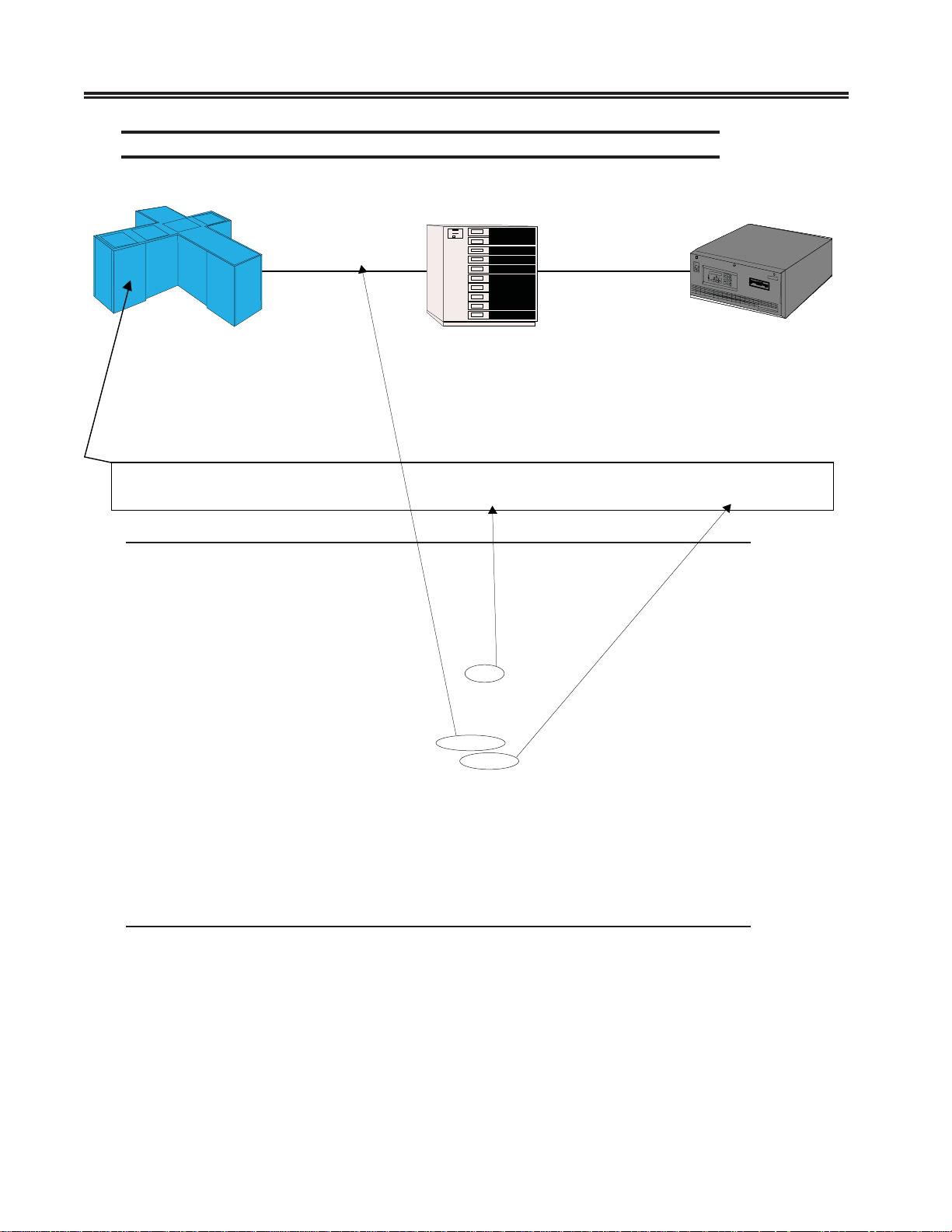
SCON Line Options/ESC Panel - (Non-SNA with Channel P ath Filter)
Port
B9
Port
07
Port
C8
ESC1
Host
ESCON
SCON
rector
IOCDS
CNTLUNIT CUNUMBR=1100,PATH=B9,UNITADD=((A0,16)),UNIT=3174,CUADD= 0
Line Options/ESC1 LINCS C8.2 Central Control
CU Index: 0
Protocol: Non-SNA with Channel Path Filter
Device Low (Lowest IODEVICE UNITADD): A0
Device High (Highest IODEVICE UNITADD: AF
CHANNEL PATH FILTER
LPAR Number (Partition Number): 3
Source Link Address: 07
CU Number (CUADD): 0
HOT SESSION SELECTION MATRIX
(Hot Session 00 corresponds 0 1 2 3
to Device Low) ———> 01234567890123456789012345678901
------------------------------- Hot Sessions MOD Size (0=Disabled): 00000000000000000000000000000000
Shared Sessions: 00000000000000000000000000000000
PF: 1-Menu 4-Add 5-Delete 7-Back 8-Forw 9-Default 10-Done
The example shows the Device Low field information being provided by the IOCDS
definition for the corresponding CNTLUNIT macro, UNIT ADD parameter . The second
part of the UNIT ADD parameter giv es the quantity of consecutive addresses def ined as
a decimal number . This number is converted from decimal to hexadecimal and used to
calculate the Device High field information. The CU Number field is also taken from
the IOCDS definition as the CU ADD value. The Source Link Address is not taken from
3-2 707054-005
the IOCDS, but is instead defined as the port on the ESCON director that is connected
Di
back to the Host CPU. If there is no ESCON director, the v alue should be left as FF or
can be defined as 01. The CU Index f ield is an index value that only has meaning to the
SCON’s configuration for referencing to the Host Circuit later.
Caution
Do not define a range of addresses on the SCON that is greater than that defined in the host
gen. Doing so can have negati ve impact on the performance of the e xisting consoles.
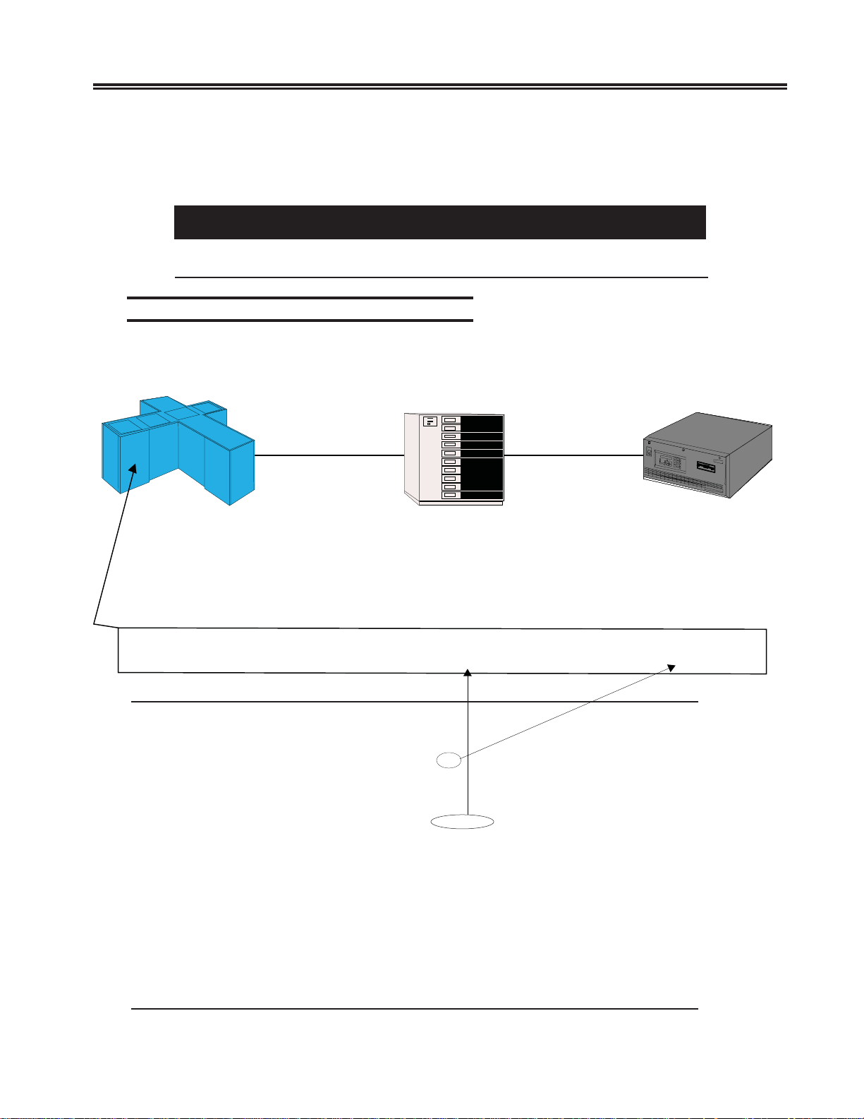
SCON Line Options/ESC Panel - (Non-SNA)
Chapter 3. Configuring the SCON
Port
B9
Port
07
Port
C8
ESC1
Host
ESCON
SCON
rector
IOCDS
CNTLUNIT CUNUMBR=1100,PATH=B9,UNITADD=((A0,16)),UNIT=3174,CUADD= 0
Line Options/ESC1 LINCS C8.2 Central Control
CU Index (CUADD): 0
Protocol: Non-SNA
Device Low (Lowest IODEVICE UNITADD): A0
Device High (Highest IODEVICE UNITADD: AF
HOT SESSION SELECTION MATRIX
(Hot Session 00 corresponds 0 1 2 3
to Device Low) ———> 01234567890123456789012345678901
------------------------------- Hot Sessions MOD Size (0=Disabled): 00000000000000000000000000000000
Shared Sessions: 00000000000000000000000000000000
PF: 1-Menu 4-Add 5-Delete 7-Back 8-Forw 9-Default 10-Done
707054-005 3-3

SCON-20L/22L/25L/28L/3074 Planning and Installation Guide
When selecting ‘Non-SNA’ as the protocol, the Device Low and De vice High fields are
derived the same way as before. The CUADD value is combined with the CU Index
field. (This restricts each CUADD def ined to being a unique value.) To compensate for
not defining the Source Link Address and LPAR values in the SCON’s configuration,
you must configure the Device Candidate List in the HCD to restrict communication to
be between the desired LPAR and a single CNTLUNIT definition.
One 3270 Host Circuit panel must be defined for each CU definition that the SCON is to
communicate with. Each 3270 Host Circuit panel must reference the CU (CUADD) that
it is to be associated with. This is done by entering the correct CU Index number
corresponding to the desired CU. Each CU supports one host circuit. T erminals used as
consoles to manage the LPAR will be assigned to the host circuit on a later panel.
The Host Identifier field is an information field only , that can be displayed on the attached
coax terminals that are making use of this host circuit. It could be used to give the name
of the LPAR, for example.
SCON-3270 Host Circuit Panel
3270 Host Circuit A LINCS C8.2 Central Control
Line: ESC1
Host Identifier: OS390_prod4
CU: 0
PF: 1-Menu 3-Def_Dflt 4-Add 5-Delete 7-Back 8-Forw 9-Default 10-Done
Configuring for Traditional Coax Displays
(does not apply to SCON-3074)
After the host side of the configuration has been made, you can configure for direct
attached coax devices. Not all device related panels are cov ered here, only the ones that
are most relevant.
One option on the Device Options/General Panel should be avoided in most instances,
the Delayed Power On Notify option.
3-4 707054-005

Chapter 3. Configuring the SCON
Device Options/General Panel
Device Options/General LINCS C8.2 Central Control
Time Of Day: Disable
Null Space Conversion: Off at Control Unit IML
Delayed Power On Notify: Disable
PASSWORD OPTIONS (must use PF4 to save changes)
ASCII/TELNET Password: synergy
Number of Days Password is valid: 021
Password Last Updated: 10 18 2004
Password Expires On: 11 08 2004
RECORD PLAYBACK OPTIONS
Length of Each Global Sequences (K): 00
Length of Device Sequences (K): 00
PF: 1-Menu 4-Update Password 7-Back 8-Forw 9-Default 10-Done
It is very important to leave the configuration for Delayed Power On Notify disabled
when you have a single terminal supporting more than one console session. If you do
not, the background sessions will not automatically be activated as consoles when the
LP AR comes up, and will instead roll to an alternate console. The default setting for this
option is “Disabled”.
Device Profile panels are used to define the feature options that are to be supported for
the devices (consoles) assigned to use that profile. One prof ile can be defined and assigned
for use by multiple consoles. All CUT consoles (coax terminals, ASCII terminals, T elnet
terminals, StorageTek LMUs) must have a device profile assigned to it. Printers (coax
printers, ASCII printers LAN-attached printers) also require a device profile. TN3270
consoles and TN3287 printers are restricted to the features supported by their emulator
and do not make use of device profiles on the SCON.
Note: A separate profile should be created for coax devices that will require file transfer
to be enabled (such as the StorageTek LMU). Creating a separate profile for
the devices requiring file transfer capability will result in better performance
(improved response time) in general, and specifically for coax de vices that do
not require file transfer.
707054-005 3-5

SCON-20L/22L/25L/28L/3074 Planning and Installation Guide
SCON Device Profile Panel
Device Profile 00/Host Assignments LINCS C8.2 Central Control
Profile Name: ________
Device Type: Display
Power Off Action: None
Session Host Assignments At Power On
------- ---------------------------A 3270 Host: OS390_prod4
B 3270 Host: VMESA_prod3
C Disable
D Disable
E Disable
F Disable
G Disable
H Disable
I Disable
J Disable
PF: 1-Menu 3-Def_Dflt 4-Add 5-Delete 7-Back 8-Forw 9-Default 10-Done
Each console or printer can be assigned to have up to 10 sessions spread across any of
the host circuits previously defined. The device profile allows you to define which of
the host circuits the device will have access to and which of the ten sessions will have
host circuits assigned. In the example above, any display (console) device assigned to
use this profile will have access to two host circuits (two LPARs). Up to 32 different
device profiles can be created.
An LMU requires that a separate coax connection be used for every LPAR that it is to
communicate with. The device profile for an LMU should only ha v e a host assignment
for Session A.
Once all of the device profiles hav e been defined, they can be assigned to the coax ports
as needed on the Device Profile Assignments panel. The PF3 function key is used to
invok e default address assignments to the panel, once you have made the De vice Profile
assignments in the appropriate column.
Note: All host address ranges are referenced from zer o on this panel, regardless of
the actual address range defined on the Line Options panel for the ESCON
interface. So, for example if the range of addresses defined on the Line Options
panel are from 20-3F , the range of addresses used on this panel w ould be from
000-031 (decimal) or 000-01F (hexadecimal).
3-6 707054-005

Chapter 3. Configuring the SCON
SCON Device Profile Assignments Panel
Device Profile Assignments/MCC1 LINCS C8.2 Central Control
Dev --------- Host Assignment At Power On (Hex LUs)------
Port Prof A B C D E FGHIJ
---- ---- ----- ----- ----- ----- ----- ----- ----- ----- ----- ----000 00 00 000 01 000 __ ___ __ _____ ___ __ ___ __ ___ __ ___ __ ___ __ ___
001 00 00 001 01 001 __ ___ __ _____ ___ __ ___ __ ___ __ ___ __ ___ __ ___
002 00 00 002 01 002 __ ___ __ _____ ___ __ ___ __ ___ __ ___ __ ___ __ ___
003 00 00 003 01 003 __ ___ __ _____ ___ __ ___ __ ___ __ ___ __ ___ __ ___
004 00 00 004 01 004 __ ___ __ _____ ___ __ ___ __ ___ __ ___ __ ___ __ ___
005 01 00 005 __ ___ __ ___ __ _____ ___ __ ___ __ ___ __ ___ __ ___ __ ___
006 01 01 005 __ ___ __ ___ __ _____ ___ __ ___ __ ___ __ ___ __ ___ __ ___
007 00 00 006 01 006 __ ___ __ _____ ___ __ ___ __ ___ __ ___ __ ___ __ ___
008 00 00 007 01 007 __ ___ __ _____ ___ __ ___ __ ___ __ ___ __ ___ __ ___
009 00 00 008 01 008 __ ___ __ _____ ___ __ ___ __ ___ __ ___ __ ___ __ ___
010 00 00 009 01 009 __ ___ __ _____ ___ __ ___ __ ___ __ ___ __ ___ __ ___
011 00 00 00A 01 00A __ ___ __ _____ ___ __ ___ __ ___ __ ___ __ ___ __ ___
012 00 00 00B 01 00B __ ___ __ _____ ___ __ ___ __ ___ __ ___ __ ___ __ ___
013 00 00 00C 01 00C __ ___ __ _____ ___ __ ___ __ ___ __ ___ __ ___ __ ___
014 00 00 00D 01 00D __ ___ __ _____ ___ __ ___ __ ___ __ ___ __ ___ __ ___
015 00 00 00E 01 00E __ ___ __ _____ ___ __ ___ __ ___ __ ___ __ ___ __ ___
(00 - 7F)3270 HOST (=)3270 Class (>)TELNET (%)Print Q (+)LAT (&)ASCII
PF: 1-Menu 3-Asn_Dflt_LUs 7-Back 8-Forw 9-Default 10-Done
The Device Profile Assignments panel is arranged with the coax port number (or ASCII
Port, or LAN port) in the far left column, profile number assigned in the second column,
then 10 sets of columns for the ten sessions supported. Each set of sessions columns
actually consist of two columns, the first to indicate the host circuit being used and the
second to give the address being used, using a zero reference to refer to the first actual
address in the range.
StorageT ek LMUs must be attached to the SCON-2XL using a separate coax connection
for each LPAR. In the example above, ports MCC1.005 and MCC1.006 represent
connections to two host circuits communicating with two different LPARs. Note the
different device profile (01) being used to provide FTP support (example of Device
Profile 01 shown on next page). In most conf igurations you will need to customize the
host and LU columns beyond what the 2XL defaults, to map the connections to meet
your requirements.
Changes can be made to the sessions columns by manually typing over the host and LU
assignments. Note that <PF3> will restore Host and LU default assignments based on
the Device Profile selection. Once you have customized this panel manually do not
press the <PF3> key or your work will be reset back to the default.
707054-005 3-7

SCON-20L/22L/25L/28L/3074 Planning and Installation Guide
Special Considerations for StorageTek LMUs
There are two special requirements on the SCON-2XL when configuring for the
StorageT ek LMUs.
• Enable the PC File Tr ansfer option on the Device Profile used by the LMUs.
• Set the Coax Poll Rate to enhanced.
Enabling PC File Transfer for StorageTek LMU
Device Profile 00/Display LINCS C8.2 Central Control
Supervisor Authority: Disable Keyboard Tables: Host Language
Windowing: Disable PC File Transfer: Enable
Calculator: Disable SNA Data Display: After Chain
Typeahead: Disable HAP Session: Last
RPB Record Function: Disable HAP Status at IML: Enable
Display Host ID: Disable HAP Profile: __
Session Auto Swap: Disable Auto Coax Recovery: Disable
RESOURCE AUTHORIZATION MATRIX
0 1 2 3 Dynamic
Resource Definition 12345678901234567890123456789012 Access
------------------- -------------------------------- ------ 3270 Host Class Access(01-32) 00000000000000000000000000000000 0
3270 Host Class Access(33-64) 00000000000000000000000000000000
ASCII Host Class Access 0000000000000000 0
IP Host Class Access 0000000000000000 0
LAT Host Class Access 0000000000000000 0
Printer Class Access 0000000000000000 0
Global Sequence Access 000000000000000000000000
PF: 1-Menu 3-Def_Dflt 4-Add 5-Delete 7-Back 8-Forw 9-Default 10-Done
The PC file transfer option is part of the Display Profile options.
The Coax Poll Rate option is found on the Coax Multiplexing menu.
Enabling Coax Poll Rate f or StorageTek LMU
Coax Multiplexing LINCS C8.2 Central Control
Method of Connection on MCC1 Standard
MCC2 Standard
MCC3 Standard
MCC4 Standard
Dynamic Multiplexing Disable
Coax Poll Rate Enhanced
Automatic Coax Recovery Disable
PF: 1-Menu 7-Back 8-Forw 9-Default 10-Done
3-8 707054-005

Chapter 3. Configuring the SCON
Configuring for Hot Console Sessions
Hot Console Sessions give you the ability to create a console session that will appear to
be powered on to the LPAR for as long as the SCON is online. This may be convenient
for situations where it is desired to have a console session that can be accessed across a
network connection by either one person or by multiple persons. Since the console
device always appears to be powered on, it should not be necessary to v ary the console
active when establishing a new connection to the session, as long as the SCON was
active when the LPAR came up.
Since the device always appears to be powered on, the console function will never roll
to another device, as long as the SCON is powered on. If the SCON is ev er powered of f
when the LPAR becomes active, or if the SCON is taken out of service, the console
function would roll to its backup per normal console operations.
Any of the SCON sessions can be configured to be hot. Note that only the console
sessions should be configured as hot (not the normal VTAM sessions).
The following panel shows how you would configure for Hot Sessions. The example
shows hot sessions for addresses A1 and A8.
Line Options/ESC1 LINCS C8.2 Central Control
CU Index: 0
Protocol: Non-SNA with Channel Path Filter
Device Low (Lowest IODEVICE UNITADD): A0
Device High (Highest IODEVICE UNITADD): AF
CHANNEL PATH FILTER
LPAR Number (Partition Number): 3
Source Link Address: 07
CU Number (CUADD): 0
HOT SESSION SELECTION MATRIX
(Hot Session 00 corresponds 0 1 2 3
to Device Low) ———> 01234567890123456789012345678901
--------------------------------Hot Sessions MOD Size (0=Disabled): 01000000100000000000000000000000
Shared Sessions: 00000000000000000000000000000000
PF: 1-Menu 4-Add 5-Delete 7-Back 8-Forw 9-Default 10-Done
Hot Session configuration is only av ailable with the Extended Feature Set option.
707054-005 3-9

SCON-20L/22L/25L/28L/3074 Planning and Installation Guide
Configuring for Telnet Clients (does not apply to SCON-3074)
T elnet clients can be conf igured as CUT displays and used for consoles. Just about any
T elnet client can be supported by one of the emulations provided by the LINCS software
running on the SCON. Additional device drivers can be created by use of the ASCII
Definition Utility (ADU) of the SCON.
Changes to the existing ASCII device drivers can also be made using the ADU.
The 20L supports up to 16 Telnet clients, the 22L supports up to 32, and the 25L and
28L may each be configured to support up to 256. Supporting more than 32 Telnet
clients on the 25L and 28L requires the installation of the T elnet F AD. The SCON-3074
does not support TELNET client.
Line Options Panel - FET Card
Line Options/FET1 LINCS C8.2 Central Control
LAN Address: 0000 0000 0000
Media Type: Auto Negotiate
Duplex Mode: Auto
TCP/IP: Enable
Coax Ethernet Bridge: Disable
PF: 1-Menu 7-Back 8-Forw 9-Default 10-Done
TCP/IP protocol is enabled for the Ethernet adapter (FET1).
A MAC address can be configured, or you can put all 0’s in the LAN Address field to
use the burned in address found on the Ethernet card.
Configuring for Token Ring instead of Ethernet will result in a similar set of panels
and options.
3-10 707054-005

Chapter 3. Configuring the SCON
Line Options - TCP/IP Options
Line Options/FET1 LINCS C8.2 Central Control
TCP/IP OPTIONS
IP Address: 207 015 182 037
Subnet Mask: 255 255 255 000
TELNET Host Connections: 000
TN3270 Client Connections: 0032
IP Router: Disable
BSD 4.2 IP Broadcast: Disable
Expanded IP Addressing: Disable
TCP Quiet Time (sec): 0000
Default Router Address: 207 015 182 001
DNS Primary Name Server: ___ ___ ___ ___
DNS Secondary Name Server: ___ ___ ___ ___
DNS/Ping Response Time: 0000
DNS Default Domain:
_____________________________________________________________
SNMP Trap IP Address: ___ ___ ___ ___
SNMP Read Authentication String: ________________
SNMP Write Authentication String: ________________
PF: 1-Menu 7-Back 8-Forw 9-Default 10-Done
The IP address and subnet mask to be used by the SCON are defined on this panel. The
Default Router must be configured if the clients are not to be connected to the same
network segment as the SCON. For security reasons a separate network for Telnet
clients may be desired.
Network Device Definition Panel - Telnet Client Definition
Network Device Definition 000 LINCS C8.2 Central Control
LAN Line: FET1 Device Type: TELNET Display
0123456
0123456789012345678901234567890123456789012345678901234567890123
Ports: 1110000000000000000000000000000000000000000000000000000000000000
In Use: 0000000000000000000000000000000000000000000000000000000000000000
7 8 9 10 11 12
4567890123456789012345678901234567890123456789012345678901234567
Ports: 0000000000000000000000000000000000000000000000000000000000000000
In Use: 0000000000000000000000000000000000000000000000000000000000000000
TCP Port 00939
IP Address or Name: ________________________________
PF: 1-Menu 4-Add 5-Delete 7-Back 8-Forw 9-Default 10-Done
Three Telnet clients are defined, connecting to the SCON on TCP port 939. Any client
configured to connect to the SCON on port 939 can get one of these three connections.
707054-005 3-11

SCON-20L/22L/25L/28L/3074 Planning and Installation Guide
The selection of port 939 was arbitrary. Selecting a port other than 23 (default Telnet
port) adds another level of security.
Note that 128 ports are shown on the panel, regardless of how man y the model supports.
An error message should appear if you attempt to exit the panel with too many Telnet
clients configured.
Network Device Definition Panel - Telnet Client Definition
Network Device Definition 001 LINCS C8.2 Central Control
LAN Line: FET1 Device Type: TELNET Display
0123456
0123456789012345678901234567890123456789012345678901234567890123
Ports: 0001000000000000000000000000000000000000000000000000000000000000
In Use: 1110000000000000000000000000000000000000000000000000000000000000
7 8 9 10 11 12
4567890123456789012345678901234567890123456789012345678901234567
Ports: 0000000000000000000000000000000000000000000000000000000000000000
In Use: 0000000000000000000000000000000000000000000000000000000000000000
TCP Port 00962
IP Address or Name: 207.15.182.197_____________
PF: 1-Menu 4-Add 5-Delete 7-Back 8-Forw 9-Default 10-Done
By specifying an IP address on the above panel, you can restrict use of this Telnet port
definition to only the workstation using the configured address. Again, a non-default
TCP port adds more security. (Note the ports def ined in the previous panel are reflected
in the “In Use” row.)
Device Options/General Panel
Device Options/General LINCS C8.2 Central Control
Time Of Day: Disable
Null Space Conversion: Off at Control Unit IML
Delayed Power On Notify: Disable
PASSWORD OPTIONS (must use PF4 to save changes)
ASCII/TELNET Password: synergy
Number of Days Password is valid: 021
Password Last Updated: 10 18 2000
Password Expires On: 11 08 2000
RECORD PLAYBACK OPTIONS
Length of Each Global Sequences (K): 00
Length of Device Sequences (K): 00
PF: 1-Menu 4-Update Password 7-Back 8-Forw 9-Default 10-Done
3-12 707054-005
 Loading...