

Visara SCON-20L Reference Manual

SCON-20L/22L CONSOLE CONCENTRATOR
Hardware Reference Manual
P/N 707043-005
ELUDEHCSNOISIVER/EUSSI
stnemmoC.oN.veRetaD
esaeleRlaitinI
etadpUarasiV
etadpU
etadpU
etadpU
100-340707
200-340707
300-340707
400-340707
500-340707
00/03/5
00/03/01
10/51/3
20/50/9
50/12/9
ii 707043-005

Read This First
This is the SCON-20L/22L Hardware Reference Manual. Information on
the LINCS Operating System can be ordered separately. Please visit our
website, www.visara.com, to access all manuals online.
1. From your Internet browser type http://www.visara.com
2. Select Service Support
3. Select Product Manuals Online
4. Select one of the following:
•
SCON-20L/22L Hardware Reference Manual
•
SCON-20L/22L/25L Configuration Manual
•
SCON-20L/22L/25L Installation Guide
•
1174 LINCS Features
•
1174 LINCS Problem Determination
•
1174 LINCS Configuration
•
1174 LINCS Central Control
707043-005 iii

Product Safety
The SCON-20L/22L Console Concentrator complies with relevant product safety standards, such as the
UL and CSA, and TUV-GS Rules and Regulations.
FCC and CDC Regulatory Statements
This equipment has been tested and found to comply with the limits for a Class A computing device,
pursuant to Part 15 of the FCC Rules. These limits are designed to provide reasonable protection against
harmful interference in a commercial installation. This equipment generates, uses, and can radiate radio
frequency energy and, if not installed and used in accordance with the instructions, may cause harmful
interference to radio communications. However, there is no guarantee that interference will not occur in a
particular installation. If this equipment does cause harmful interference to radio or television reception,
which can be determined by turning the equipment off and on, the user is encouraged to try to correct the
interference by using one or more of the following measures:
• Reorient or relocate the receiving antenna.
• Increase the separation between the equipment and the receiver.
• Connect the equipment into an outlet on a circuit different from that to which the receiver is connected.
• Consult the dealer or an experienced radio/TV technician for help.
This equipment has been certified to comply with the limits for a Class A computing device, pursuant to
FCC Rules. In order to maintain compliance with FCC regulations, shielded cable must be used with this
equipment. Operation with nonapproved equipment or unshielded cables is likely to result in interference
to radio and TV reception. The user is cautioned that changes and modifications made to the equipment
without the approval of the manufacturer could void the user’s authority to operate this equipment. The
user may find the following booklet prepared by the Federal Communications Commission helpful:
How to Identify and Resolve Radio-TV Interference Problems
This booklet is available from the U.S. Government Printing Office, Washington DC 20402, Stock No.
004-000-00345-4.
This digital apparatus does not exceed the Class A limits for radio noise emissions from digital apparatus
set out in the Radio Interference Regulations of the Canadian Department of Communications.
Le présent appereil numérique n’émet pas de bruits radioélectriques dépassant les limites applicables aux
appareils numériques de la classe A prescrites dans le Règlement sur le brouillage radioélectrique édicté
par le ministère des Communications du Canada.
iv 707043-005

Table of Contents
Page
Read This First ................................................................................................iii
Product Safety .................................................................................................iv
FCC and CDC Regulatory Statements ..........................................................iv
Chapter 1. Introduction ......................................................................................... 1-1
SCON-20L/22L General Description ......................................................... 1-1
SCON-20L/22L Hardware Components .................................................... 1-1
Chapter 2. Installation ........................................................................................... 2-1
Installation Checklist ................................................................................... 2-1
Printed Circuit .............................................................................................. 2-2
Unpacking Additional Printed Circuit Boards (PCBs) ......................... 2-2
Installing/Removing Printed Circuit Boards (PCBs) –
by Authorized Service Personnel Only ................................................. 2-2
Location Planning for the SCON-20L/22L................................................ 2-3
Environmental Parameters ...................................................................... 2-3
Power Requirements ............................................................................... 2-3
Supplied Cable Distance ......................................................................... 2-4
Power Cable Requirements..................................................................... 2-6
Connections .................................................................................................. 2-6
ESCON Channel Interface ...................................................................... 2-6
Indicators, Switches and Connectors ..................................................... 2-7
Attaching the ESC Interface to the Channel ......................................... 2-7
10/100 Mbps Fast Ethernet (FET) .......................................................... 2-8
LED Descriptions .................................................................................. 2-10
Coax Device Attachment .......................................................................... 2-11
Dynamic Multiplexing .......................................................................... 2-11
Device Attachment ................................................................................ 2-11
Chapter 3. Board Population ................................................................................ 3-1
Introduction .................................................................................................. 3-1
Printed Circuit Board Names ...................................................................... 3-1
Slot Population and Identification .............................................................. 3-1
Physical Slot Identification ..................................................................... 3-2
Slot Numbers and Logical Identifiers .................................................... 3-3
Board ID Assignments................................................................................. 3-3
Chapter 4. Operation ............................................................................................. 4-1
Indicators ...................................................................................................... 4-1
Operator Panel LEDs ............................................................................... 4-1
Power Switch ........................................................................................... 4-2
Keypad ..................................................................................................... 4-2
Copy Systems Disks .................................................................................... 4-3
IML Procedure ............................................................................................. 4-3
Error Types ................................................................................................... 4-5
IML Errors (ERR ___) ............................................................................ 4-5
Exception Errors (XCP ___) ................................................................... 4-6
Hardware Failures (FAIL ___) ............................................................... 4-6
Online Errors ............................................................................................ 4-7
707043-005 v

SCON-20L/22L Hardware Reference Manual
Error Indicators ............................................................................................ 4-7
Event Log ................................................................................................. 4-7
Status Line of Attached Terminal ........................................................... 4-7
Operator Panel Display ........................................................................... 4-7
Operator Panel Check Light ................................................................... 4-7
Software Merge ............................................................................................ 4-8
Warning Messages ................................................................................... 4-8
Failure Messages ..................................................................................... 4-9
Chapter 5. Assembly Installation/Removal/Replacement .................................. 5-1
Introduction .................................................................................................. 5-1
Assembly Drawing .................................................................................. 5-1
Replaceable Assemblies .............................................................................. 5-2
Covers....................................................................................................... 5-3
Circuit Board Assembly .......................................................................... 5-3
Power Supply Assembly ......................................................................... 5-4
Operator Panel ......................................................................................... 5-4
Floppy Disk Drive ................................................................................... 5-5
Mother Board Assembly ......................................................................... 5-6
New Hardware Installation Procedures...................................................... 5-7
Second CDA Installation (SCON-22L Only) ........................................ 5-7
Installation of FET Board........................................................................ 5-8
Page
Index ................................................................................................................ Index-1
vi 707043-005
Chapter 1. Introduction
SCON-20L/22L General Description
The SCON-20L/22L Console Concentrator is a powerful platform for supporting and
managing multiple logical partitions (LPARs) on mainframe hosts. The SCON-20L/
22L attaches to mainframes via one ESCON adapter and is used to configure and
monitor mainframe status. The SCON-20L supports communication with up to 3 LPARs.
The SCON-22L supports 4 LPARs, expandable up to 16. The SCON-20L/22L Console
Concentrator supports only LINCS software and is part of the Visara Communications
Server hardware family.
Information presented in this manual includes procedures for hardware installation,
basic operating instructions, and assembly removal and replacement instructions for the
SCON-20L/22L Console Concentrator.
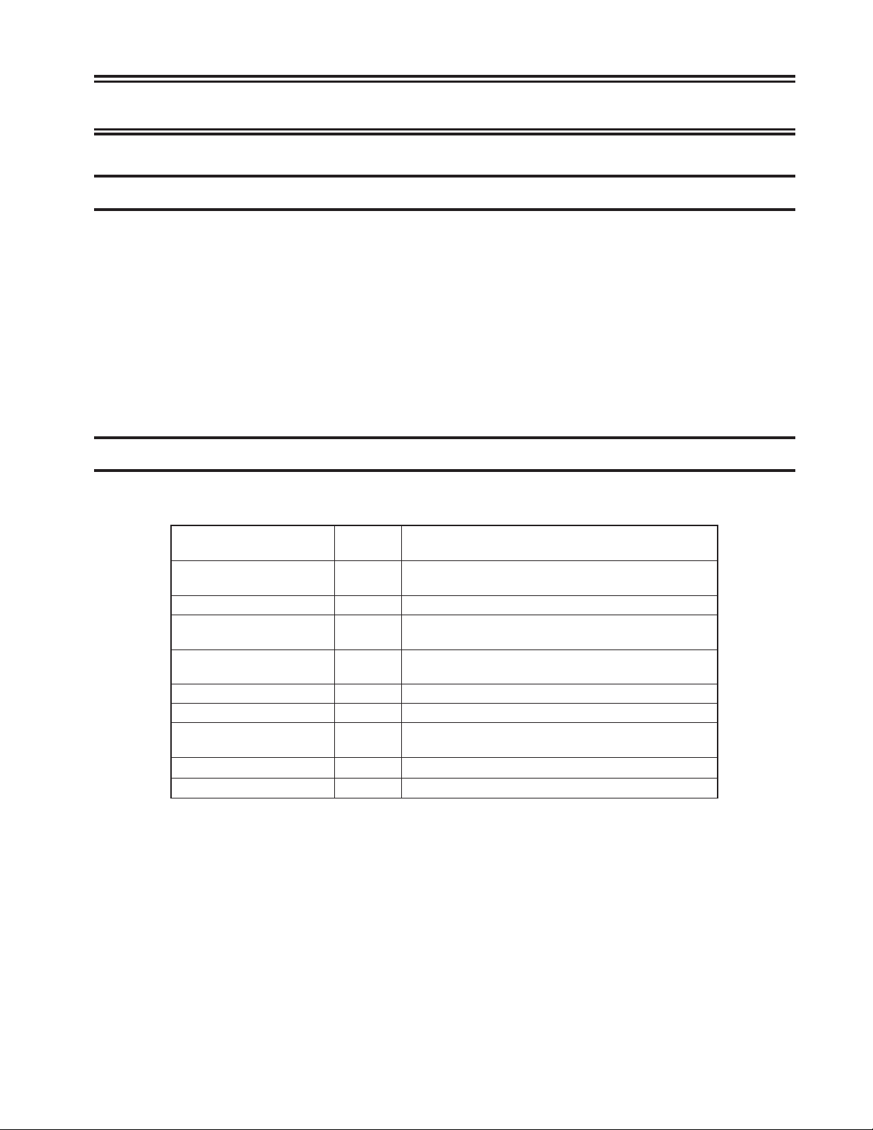
SCON-20L/22L Hardware Components
The following table includes hardware that may be installed in the SCON-20L/22L.
metIerawdraH
retpadAeciveDxaoC
)ADC(
yromeMnommoCBM4.sdraobretsamsubllaybelbisseccayromeM
CSE1
)TEF(CINtenrehtEtsaF1
virDksiDyppolF1.egarotsataD
e
evirDksiDdraH1.egarotsataD
draoBrehtoM1
lenaProtarepO1 .rellortnocehthtiwecafretnirotarepolacolsedivorP
ylppuSrewoP1 .rellortnocehtotrewopelbatss
* 2nd Coax Device Adapter only available on SCON-22L
#xaM
dellatsnI
*2
noitcnuF
.secived
owtenlennahc
.skr
.snoitc
nuf
edivorP
epytA-xaoC23otpurofnoitcennoctceridsedivorP
NOCSEotecafretninoitacinummocsedivorP
otgnicafretninoitacinummoclacisyhpsedivorP
skrowtentenrehtespbM001/01
AHSdna,CCM,PCSrofyrtiucricsniatnoC
707043-005 1-1


Installation Checklist
The following is a brief checklist of typical installation tasks for the SCON-20L/22L.
Detailed information is provided later in this chapter.
1. Check the shipping carton for any obvious shipping damage prior to unpacking.
2. Unpack the Console Concentrator per instructions provided with the shipping carton.
This unit weighs approximately 50 lbs., so please take any necessary precautions
such as seeking help with lifting.
3. Place the Console Concentrator in an appropriate location. Refer to “Environmental
Parameters.”
4. Remove the cardboard protector (if present) from the disk drive. The unit should
not be powered on with a cardboard protector in the disk drive or the disk drive may
be damaged.
5. Inspect the unit for any physical damage.
6. Install (if required) and connect 3270 Coax, ESCON, Ethernet, and/or Token Ring
cables as needed.
Chapter 2. Installation
7. Ensuring that the Power switch on the front of the Console Concentrator is off,
plug the Console Concentrator into an appropriate AC outlet.
8. Turn the Console Concentrator on (see Chapter 4, “Operation”). After a few seconds,
messages will appear on the LCD of the Operator Panel. These messages will change
as the unit proceeds through the various IML states until it has completed the boot
up procedure. When the boot has completed, the word ‘CONFIGURATION’ should
appear on the LCD. This initial boot process should take a few minutes (less than
10). If the boot process has not completed, or if you see a message that begins with
‘ERR’ or ‘XCP’, then a failure of the boot process has occurred. If a failure of the
boot process occurs, you will want to contact your Service Provider or the Visara
Intellicenter for assistance. Removal of the covers by unauthorized persons can
void your warranty.
9. Configure the Console Concentrator for use (see the SCON-20L/22L/25L/28L
Configuration Manual, SCON-20L/22L/25L/28L Installation Guide, and LINCS
Central Control manual).
707043-005 2-1

SCON-20L/22L Hardware Reference Manual
Printed Circuit
Some of the optional features require the installation of additional printed circuit boards.
WARNING
Due to electrical hazard, do not remove the system cover. Only qualified service
personnel may remove the system cover for service or installation of circuit cards.
Unpacking Additional Printed Circuit Boards (PCBs)
Follow these steps when you receive the shipment:
1. Inspect the carton for physical damage prior to unpacking.
2. If your PCBs packaging appears to have been damaged in shipment, please do not
open it. Rather, you should report the damage to the carrier upon delivery. If you
determine that your PCBs have concealed damage when you open the package,
report the damage to your carrier as soon as possible. In both situations, you should
also call Visara Customer Service to report the problem. Call 1-888-334-4380 or 1919-882-0200.
3. If you are unsure of who is providing your warranty or maintenance service, then
call the Visara Intellicenter.
4. If your PCBs fails to work properly during its initial installation or within 48 hours,
please call the Visara IntelliCenter to report the problem. Call 1-888-334-4380 or
1-919-882-0200.
5. If no damage is noted, carefully remove and unpack the package contents. Install
the printed circuit board(s) as described below.
Installing/Removing Printed Circuit Boards (PCBs) – by Authorized Service
Personnel Only
Each Circuit board assembly is plugged into connector slots on the Mother board and
fastened to the chassis with a mounting screw.
1. Ensure power is off and disconnect AC power.
2. Remove the cover.
3. Remove the mounting screw and slot cover from the selected slot.
4. Slide the board into place and ensure the connector is seated properly.
5. Secure the board into place by installing the mounting screw (removed in
Step 3).
6. Connect all required cables to the Circuit board installed.
7. Reinstall the cover.
8. Reconnect AC power and turn the unit on.
It is required that any empty slot have a slot cover installed to provide proper ventilation.
2-2 707043-005
Location Planning for the SCON-20L/22L
Use the following environmental parameters, power requirements, and cable distance
tables to aid in selecting a location for the 20L/22L.
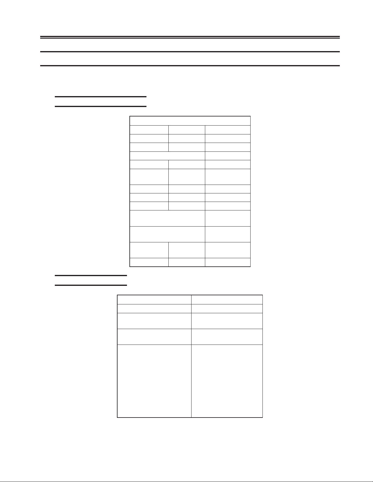
Environmental Parameters
L22/L02-NOCSsretemaraPlatnemnorivnE
:snoisnemiD
:thgieW
:secnaraelC
taeH
:tuptuO
:htdiW)mc5.44("5.71
:htpeD)mc15("02
:thgieH)mc02("8
:tnorF)mc16("42
:raeR
:poT)mc0("0
:tfeL)mc5("2
:thgiR)mc5("2
:egnaRerutarepmeT
:ytidimuHevitaleR
:tinUesaBrh/UTB013
:mumixaMrh/UTB006
K7.22(.bl05
)g
"21-01
)mc03-52(
F°501ot°05
)C°6.04ot°01(
htiw%08ot%8
noitasnednocon
Chapter 2. Installation
Power Requirements
stnemeriuqeRrewoPL22/L02-NOCS
:sesahP
:rewoP
:gnitaRtnerruC
1
AV031tinUesaB
AV042mumixaM
)zH06CAV511(A0.3
5CAV032(A4.1
)zH0
)zH06/05ta(V001
)zH06ta(V721
)zH06/05ta(V022
)zH06/05ta(V011
:)zH1-/+,%01-/+(egatloV
a(V002
)zH06/05t
)zH05ta(V032
)zH06ta(V021
)zH06ta(V802
)zH06/05ta(V042
707043-005 2-3
SCON-20L/22L Hardware Reference Manual
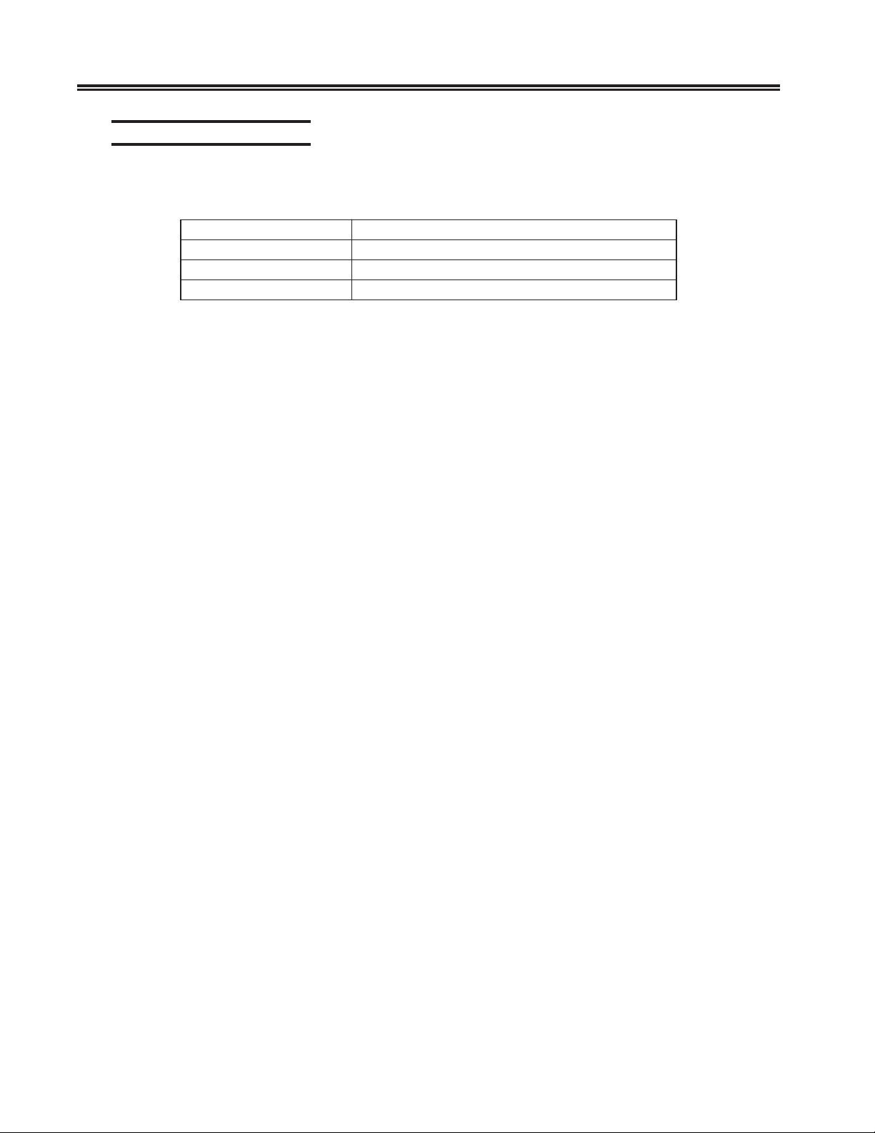
Supplied Cable Distance
The following table contains typical maximum distance information for some types of
cable used with the Console Concentrator:
epyTelbaCecnatsiDdeilppuS
elbaCrewoP)m75.4(tf51
selbaCeciveDxaoC.1-2erugifeeS
elbaCcitpOrebiFNOCSE.wolebdetsilslaunamehtotrefeR
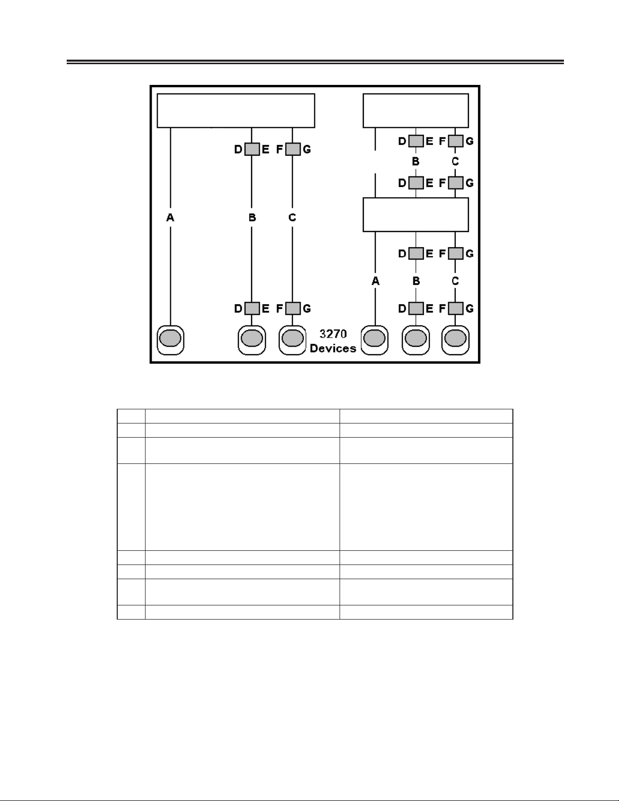
Use Figure 2-1 and the table on the following page to determine the typical maximum
allowable cable distance between the Console Concentrator and an attached device. If
your system has a multiplexer, you can install the maximum length of cable between the
Console Concentrator and the multiplexer and again between the multiplexer and an
attached device.
Additional information about cable types and distances is available in the following
IBM Publications:
Using the IBM Cabling System with Communication Products, GA27-3620
IBM Cabling System Planning and Installation Guide, GA27-3361
IBM System/360 and System/370 I/O Interface Channel to Control Unit Original
Equipment Manufacturers’ Information, GA22-6974
A Building Planning Guide for Communication Wiring, G320-8059
IBM Enterprise Systems Architecture/390, ESCON I/O interface, and Physical Layer
Specification SA23-0394
2-4 707043-005
Chapter 2. Installation
SCON-20L/22LSCON-20L/22L
A
1199-2A/C16/C32
Figure 2-1. Coax Device Cable Types and Lengths
edoCrotcennoCro/dnaaideMelbaChtgneLelbaC
AelbaClaixaoC)m0051(tf0294
BaideMdeificeps3epyTMBI
C9dna,2,1sepyTmetsySgnilbaCMBI
DretpadAriaP-detsiwT-ot-xaoC0723)m5.5(tf81
ErotcennoC3epyTCPDMBI)m5.4(tf51
F
GelbaCtnemhcattArotcennoCesopruPlauD)m9(tf03ro)m4.2(tf8
nulaB
xaoCssel-elbaCroylbmessAnulaBxaoC
01
:2dna1sepyT
lab1htiW
ulab2htiW
muminim)m5.03(tf0
mumixam)m572(tf009
)m0051(tf0294-snulab0htiW
)m0001(tf0823-nu
)m016(tf0002-snulab2htiW
)m766(tf6812-nulab1htiW
)m604(tf3331-sn
)m9.4(tf61ro)m4.2(tf8
Note: When using Type 3 media, a connector with a special actuator and filter (such
as IBM’s DPC-T3) is required in order to connect devices equipped with a
DPC. Otherwise, a Balun assembly is used.
)m0001(tf0823-snulab0htiW:9epyT
The following limitations apply to the use of these devices:
1. (coax length) + (5 * twisted pair length) <= 4500 ft (1375 m)
2. (minimum twisted pair length) => 100 ft (30.5 m)
707043-005 2-5

SCON-20L/22L Hardware Reference Manual
Power Cable Requirements
For units operating at 100-120V: The power cable required for domestic units is a UL
listed, CSA certified, 18/3 AWG, type SJT, cable (15-foot [4.57-meter] maximum). It is
terminated on one end by a 125V, 15A grounding type attachment plug. It is terminated
at the other end by a 125V, 15A parallel blade, grounding type attachment plug.
For units operating at 200-240V: The power cable required for domestic units is a UL
listed, CSA certified, 18/3 AWG, type SJT, cable (15-foot [4.57-meter] maximum). It is
terminated on one end by a 250V, 15A grounding type attachment plug. It is terminated
at the other end by a 250V, 15A tandem blade, grounding type attachment plug.
The power cable required for international units is an 18/3 AWG, type SJT, cable (15foot [4.57-meter] maximum). It is terminated on one end by a 250V, 15A grounding
type attachment plug body. It is terminated at the other end by a 250V, 15A grounding
type cord connector. The cord set is marked HAR to signify appropriate safety approvals.
The socket outlet must be nearby and easily accessible, per IEC 950 Sec. 1.7.2.
The installation site must provide a properly wired and grounded power outlet. Circuits
connected to air conditioners and devices that generate significant transient electrical
noise should be avoided.
Electrostatic discharge in the vicinity of the unit should be minimized by avoiding high
resistance floor material and carpeting that does not have antistatic properties, avoiding
the use of plastic seats and covers, and avoiding low humidity levels. The unit should be
located away from areas that generate electromagnetic interference (for example,
transformers, power distribution panels, and motors). The unit should not be installed
where the atmosphere contains corrosive elements that may damage the unit.
Cable runs should avoid areas that produce electromagnetic interference (for example,
near transformers, switching equipment, power distribution panels, and under carpets
where vacuum cleaning is done). Also, heavy equipment should not be moved or rolled
over the cable.
Connections
ESCON Channel Interface
An ESCON Controller (ESC), a PCI Feature Adaptor (PFA) board with a Luminex
ESCON board permanently connected/mounted in place, provides a single ESCON
Channel communications interface. The ESC provides a single channel attachment
interface for connecting the 20L/22L Console Concentrator to an ESCON director or to
a mainframe ESCON channel.
The fiber connection from the mainframe to the ESC shall be multimode 62.5/125 micron
cable for distances up to 3 kilometers with no directors, or 9 to 26 kilometers with 2
ESCON directors in series. Multimode 50/125 micron cable may also be used for
distances up to 2 kilometers with no directors, or 6 to 24 kilometers with 2 ESCON
directors in series.
2-6 707043-005
 Loading...