

Visara 1330-X02 User Manual

1330-X02 Printer
Operator’s Manual
P/N 701333-004
ELUDEHCSNOISIVER/EUSSI
stnemmoC.oN.veRetaD
esaeleRlaitinI100-33310739/13/01
etadpUlacinhceT
eussieRetelpmoC
etadpUlacinhceT
etadpUlacinhceT
eussieRetelpmoC
eussieRetelpmoC
IBM is a registered trademark of IBM Corporation.
602157100-
49/13/30
200-333107
100-602157
100-396657
300-333107
400-333107
49/01/60
49/51/90
49/02/21
69/20/20
99/11/60
© Copyright 1993, 1994, 1996 by MTX Corporation
ii 701333-004

This equipment complies with FCC regulations for EMI.
WARNING!
This equipment generates, uses, and can radiate radio
frequency energy, and, if not installed and used in accordance with the manual, may cause interference to radio
communications. It has been tested and found to comply
with the limits for a Class A computing device pursuant to
Subpart J of Part 15 of FCC Rules, which are designed to
provide reasonable protection against such interference
when operated in a commercial envir onment. Operation of
this equipment in a residential area is likely to cause interference, in which case users, at their own e xpense, will be
required to take whatever measures may be necessary to
correct the interference.
701333-004 iii

Table of Contents
Page
Chapter 1. Introduction ............................................................................................1-1
Interfacing with the 1330 ................................................................................1-2
A-Coax Attachment ....................................................................................1- 2
ASCII Attachment ......................................................................................1-3
Standard Features............................................................................................1-3
Character Codes .........................................................................................1-3
Color...........................................................................................................1-4
Paper Handling ...........................................................................................1-4
Print Qualities.............................................................................................1-4
Multiple Copies ..........................................................................................1-4
3270 Languages..........................................................................................1-4
Screen Sizes ...............................................................................................1-4
Self-Diagnostic T esting ..............................................................................1-5
Audible Alarm ............................................................................................1-5
Programmed Symbols ................................................................................1-5
IPDS ...........................................................................................................1-5
Optional Features............................................................................................1-5
Memory ......................................................................................................1-5
Continuous Forms Module .........................................................................1-5
Forms Handler Module...............................................................................1-6
Printer Pedestal Stand.................................................................................1-6
Forms Stand................................................................................................1-6
Related Manuals .............................................................................................1-6
Chapter 2. Preparing to Operate the 1330 ................................................................2-1
Inspecting the Package....................................................................................2-1
Unpacking the Printer .....................................................................................2-1
Installation Preparation ...................................................................................2-3
Installing the Ribbon Cartridge.......................................................................2-4
Ordering Ribbons .......................................................................................2-4
Installing a Shifting Ribbon........................................................................2-4
Installing a Nonshifting Ribbon .................................................................2-7
Connecting the Printer to a Power Source ......................................................2-8
Power Cable Requirements ........................................................................2-8
Connecting the Coax Cable ............................................................................2-9
Connecting a Parallel or Serial Cable ...........................................................2-10
Connecting a Parallel Cable .....................................................................2-10
Connecting a Serial Cable ........................................................................2-10
Powering on the 1330 ...................................................................................2-11
Forms Specifications.....................................................................................2-11
Installing the Forms – Continuous Forms Module........................................2-17
Setting the Platen Gap Lever ....................................................................2-20
Installing the Forms Handler Module ...........................................................2-21
Installing Forms Using the DOD Option..................................................2-21
Installing Forms Using the DID Option ...................................................2-23
Chapter 3. Operator Control Panel...........................................................................3-1
The Status Display..........................................................................................3- 1
Cu ...............................................................................................................3-2
S/C/A..........................................................................................................3-2
701333-004 v

Table of Contents
The Keypad.....................................................................................................3-3
Chapter 4. Configuring the 1330 in 3270 Mode ........................................................4-1
Configuration Procedure.................................................................................4-1
The Configuration Options .............................................................................4-5
Page
Operating Mode..........................................................................................3-2
Form Device ...............................................................................................3-2
Emulation Mode .........................................................................................3-2
Datastream Mode/Interface T ype................................................................3-3
Status Message ...........................................................................................3-3
Key Functions.............................................................................................3-3
Using the Keys ...........................................................................................4-1
Getting into the Menu Mode ......................................................................4-1
Scrolling Through Menu Selections ...........................................................4-2
Selecting a Menu Option ............................................................................4-4
Leaving Menu Mode ..................................................................................4-4
100 Page Format.........................................................................................4-5
200 Font & Print Quality ............................................................................4-8
300 Compatibility.....................................................................................4-13
400 Printer Setup ......................................................................................4-17
500 Communication .................................................................................4-25
600 Attachment.........................................................................................4-27
700 Extended Keypad...............................................................................4-28
800 Program Symbol ................................................................................4-33
900 Vital Product Data..............................................................................4-34
Chapter 5. Configuring the 1330 in ASCII Mode ....................................................5-1
Configuration Procedure.................................................................................5-1
Using the Keys ...........................................................................................5-1
Getting into the Menu Mode ......................................................................5-1
Scrolling Through Menu Selections ...........................................................5-2
Selecting a Menu Option ............................................................................5-4
Leaving Menu Mode ..................................................................................5-4
The Configuration Options .............................................................................5-5
100 Page Format.........................................................................................5-5
200 Font & Print Quality ............................................................................5-7
300 Compatibility.....................................................................................5-10
400 Printer Setup ......................................................................................5-14
500 Communication .................................................................................5-22
600 Attachment.........................................................................................5-26
700 Extended Keypad...............................................................................5-27
Chapter 6. Operating the 1330 .................................................................................6-1
Setting the Print Format ..................................................................................6-1
Specific Operating Procedures........................................................................6-2
Printing the Setup Line ...............................................................................6-2
Adjusting the Top of Form Position............................................................6-3
Storing Printer Configuration Values ..........................................................6-3
General Operating Procedures ........................................................................6-4
Reprinting the Print Buffer .........................................................................6- 4
vi 701333-004

Table of Contents
Page
Requesting a Host Application Program in SCS Mode ..............................6-5
Halting a Print Operation in SCS Mode .....................................................6-5
Chapter 7. Maintaining the 1330..............................................................................7-1
Ventilation.......................................................................................................7- 1
Cleaning the Printer ........................................................................................7-1
Replacing the Ribbon .....................................................................................7-1
Replacing the Print Head ................................................................................7-1
Checking Character W idth and Print Registration ..........................................7-5
Checking Character W idth .........................................................................7-6
Checking Print Registration .......................................................................7-7
Chapter 8. Error Detection and Recovery ................................................................8-1
T ypes of Errors................................................................................................8-1
Intervention Required Conditions...............................................................8-1
General Error Conditions ...........................................................................8-2
Unusual Error Conditions...........................................................................8-2
Appendix A. Status and Err or Message Chart ........................................................A-1
Appendix B. Programming Notes...........................................................................B-1
Programming in SCS Control Codes (Non-IPDS).........................................B-1
Set Print Density ............................................................................................B-2
Page Presentation Media................................................................................ B-2
Using Host Controlled Color/Highlighting/Symbol Set ................................B-3
LU1 Mode ................................................................................................. B-3
LU3 Mode ................................................................................................. B-4
Programming in IPDS Data Stream ...............................................................B-7
Initialization Defaults ................................................................................B-7
Command Format...................................................................................... B-9
IPDS Command Codes............................................................................ B-10
Device Control Function Set Commands ................................................ B-10
T ext Function Set Commands..................................................................B-11
Image Function Set Commands............................................................... B-11
Graphics Function Set Commands .......................................................... B-11
Bar Code Function Set Commands ......................................................... B-12
Overlay Function Set Commands............................................................B-12
Page Segment Function Set Commands ..................................................B-12
Loaded Font Function Set Commands.....................................................B-13
Using Escape Sequences in 3270 Mode.......................................................B-13
Selecting the Escape Character ............................................................... B-14
Selecting Escape Codes........................................................................... B-17
Using the Bar Code Feature .................................................................... B-19
Using Bar Code Escape Sequences ......................................................... B-21
Calculating Checksums ........................................................................... B-24
Print Optical Character Reader Parameter............................................... B-24
1330 Commands in ASCII Mode.................................................................B-27
Using Proprinter Commands in ASCII Mode ..............................................B-27
Print Mode Commands............................................................................ B-27
Horizontal Movement Commands........................................................... B-29
701333-004 vii

Table of Contents
Using TI-810 Command Functions in ASCII Mode .................................... B-38
Using Escape Sequences with ANSI Bar Codes.......................................... B-40
Appendix C. Character Sets..................................................................................... C-1
Appendix D. Consumables .....................................................................................D- 1
Ribbons..........................................................................................................D-1
Print Heads ....................................................................................................D-1
Page
Horizontal T abbing Commands ...............................................................B-30
V ertical Mo vement Commands ............................................................... B-30
V ertical T abbing Commands....................................................................B-31
Page Formatting Commands ................................................................... B-32
Bit Image Graphics Commands...............................................................B-32
Font Control and Download Commands ................................................. B-34
Character Set Selection Commands ........................................................ B-35
Language Set Selection Commands ........................................................B-35
Set Initial Condition Commands .............................................................B-36
Miscellaneous Commands....................................................................... B-37
Escape Command Strings........................................................................ B-39
Appendix E. Character Count Record..................................................................... E-1
Index ...................................................................................................................Index-1
viii 701333-004

List of Illustrations
Page
Figure 2-1. Unpacking the 1330 .................................................................2-2
Figure 2-2. Foam Shipping T ube ................................................................2-3
Figure 2-3. Shifting Ribbon Cartridge........................................................2-5
Figure 2-4. Platen Gap Lever......................................................................2-5
Figure 2-5. Disengaging the Ribbon Shifter Guide ....................................2-6
Figure 2-6. Nonshifting Ribbon Cartridge..................................................2-7
Figure 2-7. Installing the AC Power Cord ..................................................2-9
Figure 2-8. Connecting the Coax Cable .....................................................2-9
Figure 2-9. Connecting a Parallel or Serial Cable ....................................2-10
Figure 2-10. Forms Specifications - Physical Requirements......................2-12
Figure 2-11. Forms Specifications - Print Positioning................................2-13
Figure 2-12. Print Positioning - Continuous Forms....................................2-14
Figure 2-13. Print Positioning - Single Part Forms.....................................2-15
Figure 2-14. Paper Feed Slots.....................................................................2-17
Figure 2-15. Open Tractor Door .................................................................2-18
Figure 2-16. Flipping the Tractor Lever .....................................................2-18
Figure 2-17. Inserting Paper - Continuous Forms Module .........................2-19
Figure 2-18. Platen Gap Lev er....................................................................2-20
Figure 2-19. Forms Handler Module (DOD Option)..................................2-21
Figure 2-20. DOD Option with Roller Drive..............................................2-23
Figure 2-21. Forms Handler Module (DID Option) ...................................2-23
Figure 2-22. Inserting Paper - Forms Handler Module...............................2-24
Figure 2-23. DID Option with Roller Drive ...............................................2-25
Figure 3-1. 1330 Operator Control Panel ...................................................3-1
Figure 3-2. Status Display ..........................................................................3-1
Figure 4-1. Aligned and Unaligned Dots in Characters............................4-19
Figure 5-1. Aligned and Unaligned Dots in Characters............................5-16
Figure 7-1. Replacing the Print Head .........................................................7-3
Figure 7-2. Carriage Restraining Hook ......................................................7-3
Figure 7-3. Mounting Screws .....................................................................7-4
Figure 7-4. Carriage - Side View ................................................................7-5
Figure 7-5. Proper Print Registration..........................................................7-5
Figure 7-6. Increase Print Registration Value .............................................7-7
Figure 7-7. Decrease Print Registration V alue............................................7-8
Figure B-1. Escape Sequence Structure ...................................................B-13
Figure B-2. Table for Selecting Escape Character ...................................B-15
Figure B-3. Escape Codes ........................................................................B-18
Figure B-4. Bar Code T ypes..................................................................... B-20
Figure B-5. Calculating New Line Characters ......................................... B-23
Figure B-6. OCR-A Character Set ........................................................... B-25
Figure B-7. OCR-B Character Set ........................................................... B-26
701333-004 ix
Chapter 1. Introduction
The MTX 1330 Printer is designed for high-volume printing and combines high reliability
with convenient features such as modular paper handling, a 4-line, 80-character LCD
that displays menus, an automatic forms thickness adjustment, and self-diagnostic
messages. The 1330 produces clear, precise printing on up to six-part forms,
accommodates continuous forms and cut sheet paper, and operates quietly for office
environments.
A serial dot matrix bidirectional impact printer, the 1330 is av ailable in one model:
• 1330-X02
This model prints in four qualities. The maximum print speeds (at 10 CPI in monochrome)
in each quality are as follows (CPS = characters per second):
tfarDtsaF
*ytilauQ
SPC005SPC004SPC052SPC521
The 1330 is available with an 18-wire-shifting ruby print head. Output can be
monochrome, four colors or 8 colors, depending on the ribbon cartridge installed.
Comprehensive graphics support is offered through All Points Addressable (APA)
Programmed Symbols, as well as Intelligent Printer Data Stream (IPDS). The 1330 also
supports APL and 39 international character sets.
The 1330 supports several attachment cards that offer the highest possible flexibility for
your corporate printing strategy . Some of the attachment cards feature a 3270 interface
port, and parallel and serial ASCII input ports, thereby enabling automatic printer sharing
between 3270 hosts and personal workstations. (See table at the top of the following
page.)
*Fast Draft is only available in 3270 mode.
ytilauQ
gnissecorPataD
gnissecorPataD
ytilauQtxeT
retteLraeN
ytilauQ
701333-004 1-1
Introduction
sdraoBtnemhcattA stnemnorivnEnoitacinummoC
xaoCsretpadaxaoC-Ahtiwsrellortnocdnastsoh0723-
)lauD(IICSA/xaoCsretpadaxaoC-Ahtiwsrellortnocdnastsoh0723-
IICSAMBI(sretupmocinim,snoitatskrow,semarfniaM-
Interfacing with the 1330
A-Coax Attachment
,).cte,004SAMBI(sretupmocinim,semarfniaM-
htiwsretupmoclanosrepdna,snoitatskrow
laires234SR/232SRdnalellarapscinortneC
secafretni
ehtneewtebgnirahsretnirpgnihctiwsotuastroppuS
.tsohIICSAdna0723
htiwsretupmoclanosrepdna,).cte,004SA
laires234SR/232SRdnalellarapscinortneC
secafretni
The 1330 Coax can be attached to the following controllers via an A-type coax cable:
• T elex 046, 076, 274, and 276 controllers
• Memorex 2076, 2174, and 2274 controllers
• Memorex Telex 1174, 1274, and 1374 controllers
• IBM 3174, 3274, and 3276 controllers with “ A” terminal ports
• IBM 3694 Document Processor
• IBM 4321, 4331, 4341, and 4361 processors through the standard display/printer
adapter or expansion feature
• IBM 9370 processor
Emulation
The following printer emulations are av ailable as standard features on the 1330 Coax:
• IBM 3268 – Emulates a non-IPDS IBM 4224 printer with IBM 3628 programmed
symbols
• IBM 4224 – Emulates an IBM 4224 printer
• IBM 4230 – Emulates an IBM 4230 printer
• 2124 – Emulates a non-IPDS IBM 4224 printer with IBM 3268 programmed symbols
and supports escape codes to select bar codes, formatting, fonts, highlighting, OCR
printing, and so on
1-2 701333-004

ASCII Attachment
With an ASCII attachment, the follo wing features are av ailable on the 1330.
Interfaces
The following interfaces are software selectable from the front panel:
• Centronics parallel
• RS-232C
• RS-422
Emulation
The following printer emulations are available as standard features on the 1330 ASCII:
• IBM Proprinter III and III XL
• TI-810 modified
Introduction
Character Codes
In ASCII mode, the American Standard Code for Information Exchange (ASCII) character
set is recognized by the 1330. See Appendix C, “Character Sets,” for information about
ASCII character sets.
Print Buffer
In ASCII mode, the print b uffer is a reserv ed area of memory for storing incoming data
before it is printed. The buffer size is operator selecta ble for 2K, 8K, 16K, or 32K bytes.
ASCII Languages
The 1330 supports international languages through the use of its internal PC character
set. Selection is made from the front panel during printer configuration.
Standard Features
Standard features of the 1330 are described below . Information for using these printing
capabilities is presented in subsequent chapters of this manual.
Character Codes
In 3270 mode, the Extended Binary Coded Decimal Interchange Code (EBCDIC)
character set is recognized by the 1330, as well as the SNA Character String (SCS). See
Appendix B of this manual for character code charts for SCS support.
701333-004 1-3

Introduction
Color
The 1330 can print in monochrome or color, using an operator installable recirculating
cloth ribbon cartridge. Two monochrome ribbons, a 4-color accent ribbon (black, red,
blue, and green), and a subtractive 8-color r ibbon (black, red, blue, green, yello w, magenta,
cyan, and brown) are a vailable.
Paper Handling
The 1330 comes standard with pull tractors for continuous forms feeding, and allows for
easy paper loading at the front of the printer . Pinfeed forms from 3 to 14 inches (7.6 to
35.6 cm) long and 3 to 15 inches (7.6 to 38.1 cm) wide can be used. This configuration is
especially suited for a large volume of work or work that requires little operator
intervention.
Print Qualities
The 1330 can print in four qualities:
• Fast Draft Quality (FD) (av ailable only in 3270 mode)
• Data Processing (DP)
• Data Processing T e xt (DP Text)
• Near Letter Quality (NLQ)
All print qualities are selectable via the operator control panel.
Multiple Copies
The 1330 can print multiple copies, one original plus five copies, total thickness not to
exceed 0.025 inch (0.64 mm). The recommended maximum thickness for multipart forms
is 0.018 inch (0.46 mm).
3270 Languages
The 1330 enables the operator to select from 39 international language character sets.
Selection is made during printer configuration. The attached control unit should be
configured for the same language.
Screen Sizes
Any of the following display buf fer sizes can be selected for print operation:
• 1920 bytes
• 2560 bytes
1-4 701333-004

• 3440 bytes
• 3564 bytes
The size can be selected by the operator during configuration.
Self-Diagnostic T esting
The 1330 has a self-diagnostic ability to ensure that the printer is in good working
condition. If an error condition is encountered, the 1330 informs the operator by displaying
an error message on the control panel. Should this occur, refer to the er ror message chart
in Appendix A of this manual.
Audible Alarm
The 1330 features an audible alarm that sounds when the printer needs operator assistance
(such as when the paper is skewed or out). In this situation it will continue to beep
intermittently , unless it is disabled.
Programmed Symbols
Introduction
In 3270 mode, six symbol sets are operator configurable either as six single plane sets or
as three single plane sets and one triple plane set.
IPDS
Intelligent Printer Data Stream (IPDS) is a structured field datastream for managing
printing processes and data objects. IPDS uses All Points Ad dressability (AP A) to enable
the user to position text, graphics, image data, overlays, and bar codes at any defined
point on a printed page. Extended memory is recommended for graphics applications.
Optional Features
The following optional accessories are available for the 1330. These items can be ordered
through your sales representative.
Memory
This feature adds 512K bytes of RAM memory to the standard 128K bytes of memory
for a total of 640K bytes. The extra memory is recommended for the following
applications: IPDS, programmed symbols, ASCII graphics, ASCII do wnloaded fonts,
and dual host (auto-switching) operations.
Continuous Forms Module
The continuous forms module provides the operator with a reliable way of feeding the
1330 with continuous forms.
701333-004 1-5

Introduction
Forms Handler Module
The Forms Handler module is operator installable in the front of the printer to vertically
position forms. The module’ s forms tractors are adjustable for two options:
• Document on Demand (DOD) option – used for continuous forms
• Document Insertion Device (DID) option – used for cut sheet/single sheet forms
Printer Pedestal Stand
The pedestal stand is designed so that the printer can be securely seated. The forms
supply is placed in the stand’s paper compartment and feeds into the front of the 1330
from below .
Forms Stand
The forms stand is placed behind the printer to hold both new and printed fanfold forms.
Related Manuals
Appendix D of this manual contains programming information for special 1330 escape
codes.
For more information on printer control codes in Appendix B, see the IBM 4224 Printer
Product and Programming Description Manual, GC31-2551; IBM 4230 Printer Product
and Programming Description Manual, GC40-1701-00; IBM 3270 Information and
Display System, GA23-0061; IBM 3268 Printer Models 2 and 2C Description, GA273268; IBM Pr oprinter III and IIIXL Guide to Operations, SA34-2065-1; IBM Pr oprinter
F amily T echnical Reference, SC31-2589-3; and the ANSI Standar d X3.64-1979.
1-6 701333-004

Chapter 2. Preparing to Operate
The 1330 printer has been designed for customer setup and preliminary check. Please
read this chapter before you try to install or relocate your 1330.
Inspecting the Package
When the packaged 1330 printer arrives, inspect the carton for physical damage before
unpacking it. If the carton is damaged, do not open it. Notify the T raff ic De partment or
your sales representative, as appropriate.
Also call the delivery carrier to request examination of the damage. The carrier is required
to complete and sign a damage report form.
If you do not see any damage, unpack the printer according to the follo wing instructions.
Unpacking the Printer
the 1330
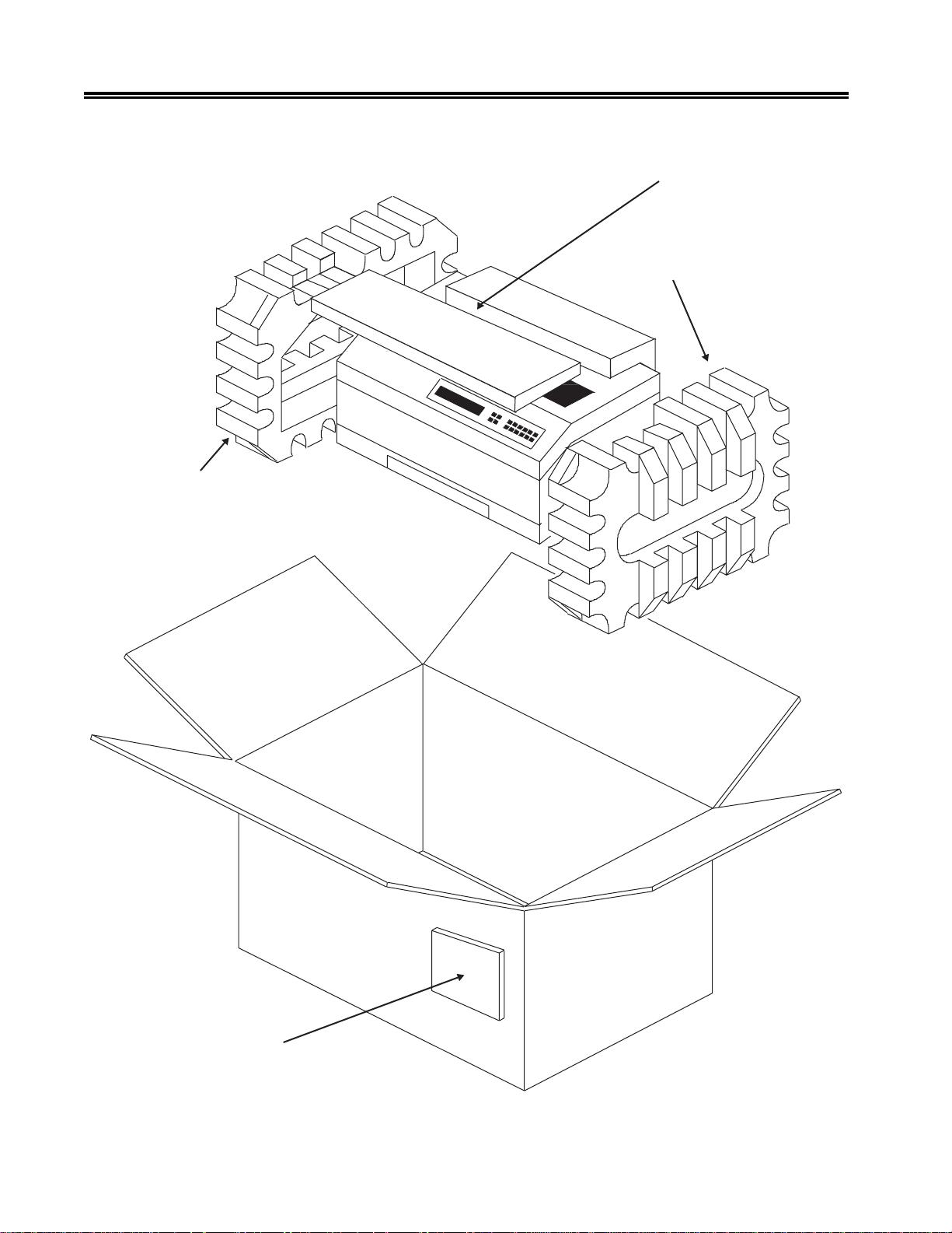
Refer to Figure 2-1 and follow these steps to unpack the 1330:
Caution
The 1330 weighs 66 pounds (29.9 kg). T w o people may be required to mov e the printer
to its operating location.
1. Move the packaged printer to the work area and place the car ton in an upright position.
2. Remove the packing list envelope from the outside of the box.
3. Open the flaps to the top of the box.
4. Remove the operator’s manual from the top of the printer .
5. Remove the continuous forms module feature (if ordered) located on top of the
printer.
6. Remove the printer from the box and remove the foam end caps and the bag from
the printer.
7. Remove the protective film from the top of the printer .
8. Lift the printer cover and remove the ribbon and power cord.
701333-004 2-1
Preparing to Operate the 1330
Left End Cap
Continuous Forms
Module Feature
Right End Cap
Packing List Envelope
Figure 2-1. Unpacking the 1330
2-2 701333-004
Preparing to Operate the 1330
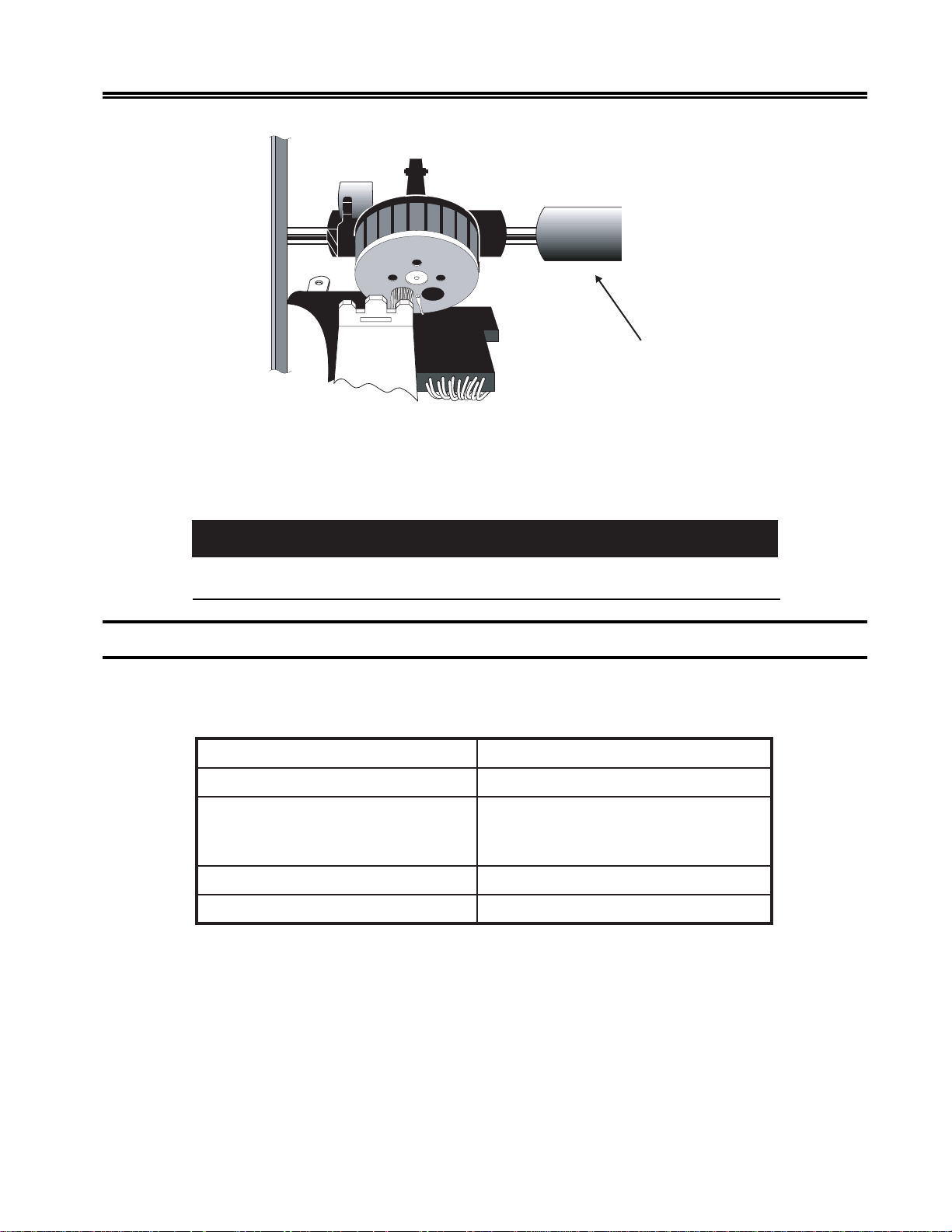
Shipping T ube
Figure 2-2. Foam Shipping Tube
9. The carriage on the 1330 is restrained by a foam shipping tube to prevent shifting during
shipping. Before installing the printer, remove this tube, illustrated in Figure 2-2.
Failure to remove the carriage shipping tube before turning on the 1330 may result in
damage to the printer.
Installation Preparation
The location for the 1330 must meet the following physical and environmental
requirements:
:rewoPesahpelgnis,zH36-74taCAV462-09
:ecnaraelCsedisllano)mc2.51(ni6
:snoisnemiDediw)mc5.56(ni8.52
:ytidimuHevitaleR)gnisnednocnon(%08ot%8
After unpacking the 1330, you are now ready to begin installing it.
Caution
hgih)mc5.13(ni4.21
peed)mc8.74(ni8.81
:egnaRerutarepmeTgnidnuorruS)C6.04-01(F501-05
701333-004 2-3

Preparing to Operate the 1330
Installing the Ribbon Cartridge
A monochrome ribbon cartridge is shipped with the 1330. Remember that if you have a
monochrome ribbon installed, the 1330 will print in one color only. A multitrack color
ribbon cartridge must be installed to allow printing in different colors.
Ordering Ribbons
Y ou can use a Shifting ribbon or a Nonshifting ribbon in the 1330-X02. The ribbons have
the same character life and for monochrome printing can be used interchangeably.
Caution
Use only approved ribbons that are av ailable from MTX. Third party ribbons may not be
compatible, resulting in improper operation and decreased print head life.
To order additional ribbon cartridges for the 1330-X02, contact your MTX Sales
Representative. Request the following ribbon cartridge part number(s):
epyTnobbiR N/PXTM
Following are instructions for installing each ribbon type.
Installing a Shifting Ribbon
This section explains how to install a Shifting ribbon cartridge. Y ou will need to install a
new ribbon when the existing ribbon wears out. Refer to Figure 2-3.
1. Make sure that the printer’s Power switch is in the O (OFF) position. Unplug the
power cord from the outlet.
2. Raise the printer cover.
3. Set the platen gap lever away from the platen (toward you) as far as it will go (see
Figure 2-4).
4. Slide the print head to the middle of the printer.
The print head may be hot. To move it, grasp the pr int head driv e belt.
gnitfihS–)tneccA(roloC-4200-078559
gnitfihsnoN–emorhconoM100-263559
Caution
2-4 701333-004
Preparing to Operate the 1330
Removable Corner Guides
Ribbon Drive
Gear Knob
Mounting Clip
Platen Gap Lever
Mounting Clip
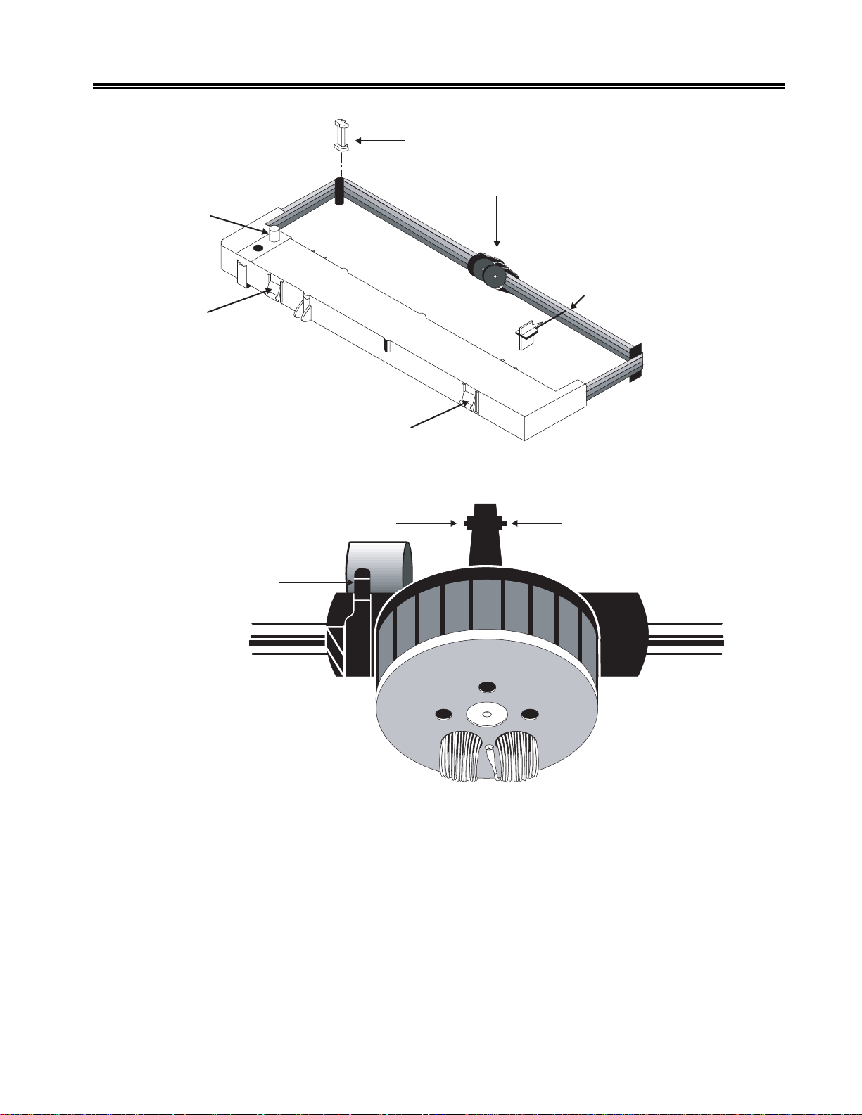
Figure 2-3. Shifting Ribbon Cartridge
Ribbon Shifter Button
Ribbon Shifter Guide
Ribbon Stop (REMOVE
AFTER INSTALLATION)
Ribbon Shifter Button
Figure 2-4. Platen Gap Lever
5. If you are replacing the ribbon cartridge, grasp both sides of the ribbon shifter guide,
as illustrated in Figure 2-5, and gently bend the sides toward the rear of the printer .
The ribbon shifter guide will disengage. Lift it away from the printer .
701333-004 2-5

Preparing to Operate the 1330
Ribbon Shifter Guide
Figure 2-5. Disengaging the Ribbon Shifter Guide
6. If you are replacing the ribbon car tridge, lift out the old cartridge and remove the
plastic corner guides. Reinstall the new corner guides (they are packed in the ne w
ribbon cartridge package) over the corner guide brackets.
7. Snap the new ribbon cartridge into place. Make sure that the tabs on the front and
back of the cartridge snap into the slots on the ribbon cartridge bracket.
8. Pull the ribbon stop out of the cartridge and put the stop aside for later use.
9. Install the r ibbon shifter guide by positioning it above the nose of the print head,
then press the guide down until it rocks into place on the ribbon shifter buttons. If
the ribbon shifter guide is properly installed, it will rotate smoothly.
Caution
Make sure that the barrel fits snugly against the print head nosepiece. Otherwise, it will
not shift properly.
10. Use the tapered end of the ribbon stop to route the ribbon around the right and left
corner guides.
11. Turn the ribbon drive gear knob counterclockwise several times to make sure the
ribbon is feeding properly .
12. Slide the print head to the far left and reset the platen gap lever to the appropriate
position to accommodate the thickness of the forms. If necessary, refer to “Setting
the Platen Gap Lever” later in this chapter. Close the printer cover.
Caution
If the platen gap adjustment is set too close to the paper, the life of the print head will be
reduced and the print head may be damaged.
13. Connect the printer to a power source, as explained later in this chapter .
2-6 701333-004
Installing a Nonshifting Ribbon
Follow these steps to install or replace a Nonshifting ribbon cartridge. Refer to Figure 2-6.
Note that the Nonshifting ribbon is monochrome only.
1. Turn the printer off and unplug the power cord from the outlet.
2. Raise the printer cover.
3. Set the platen gap lever away from the platen (toward you) as far as it will go (see
Figure 2-4).
The print head may be hot. To move it, grasp the print head driv e belt.
4. Slide the print head to the middle of the printer.
5. Grasp the ribbon guide, as illustrated in Figure 2-6, and lift it from the print head.
Preparing to Operate the 1330
W arning
Ribbon Advance Knob
Cassette T abs
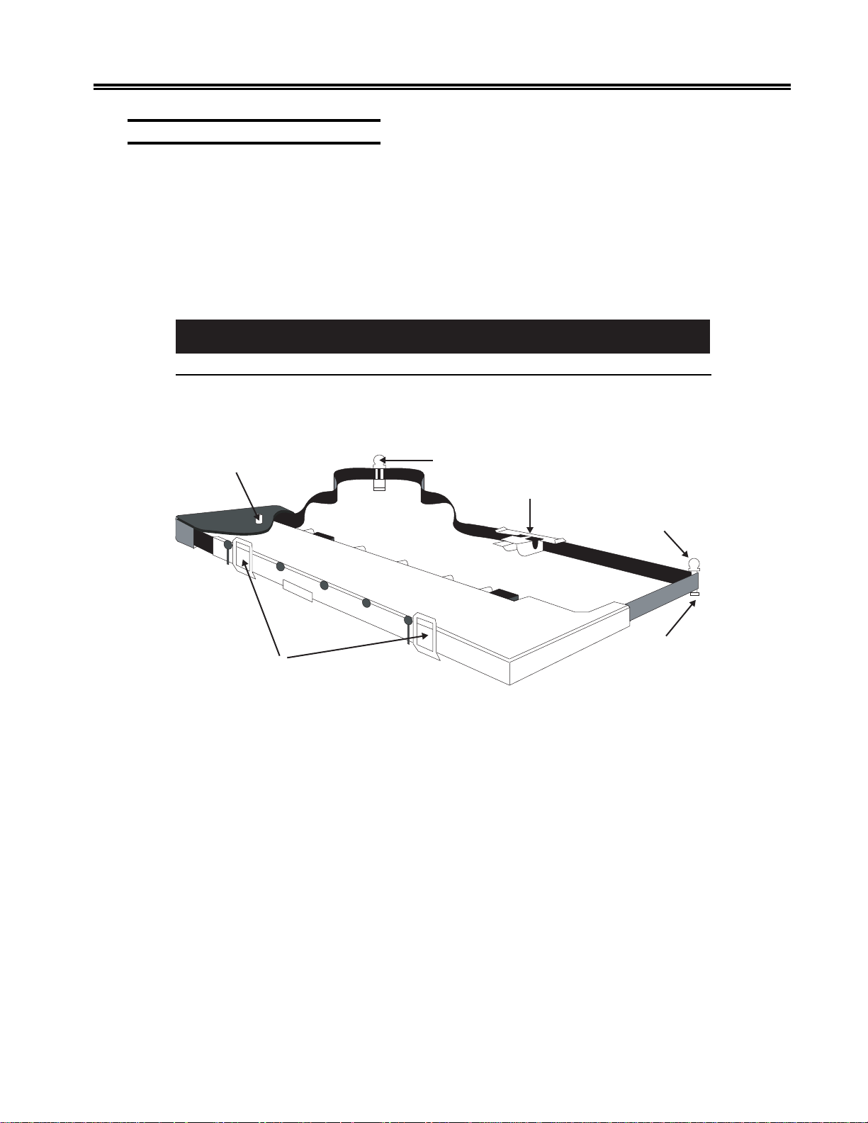
Figure 2-6. Nonshifting Ribbon Cartridge
6. Remove the used corner guides. The new corner guides are attached to the new
ribbon. (On Shifting ribbons, the corner guides are separate.)
7. Release the left end of the cartridge first. Push back the metal spring clip on the
printer, and squeeze the cassette tabs. Lift the left end of the cartridge clear, then
push the metal spring clip forward to release the right end.
8. Pull the ribbon guide from the body of the ne w cartridge and make sure the ribbon is
not twisted.
Corner Guide
Ribbon Guide
Corner Guide
Ribbon
Turning Post
9. Seat the car tridge onto the platform. Press down along the top of the cartridge to
ensure that it is firmly seated, with the cassette tabs snapped into the openings in the
platform.
10. Slide the plastic corner guides onto the ribbon turning posts while making sure the
ribbon is not twisted. Make sure that the corner guides are pressed all the way down.
701333-004 2-7

Preparing to Operate the 1330
11. Snap the ribbon guide onto the print head. The ribbon guide must fit securely on the
ribbon shifter buttons shown in Figure 2-4. Make sure the ribbon is not twisted.
12. T ak e up the ribbon slack by turning the ribbon advance knob in the direction of the
arrow .
Caution
If the platen gap adjustment is set too close to the paper, the life of the print head will be
reduced and the print head may be damaged.
13. Close the printer cover .
14. Connect the printer to a power source, as explained in the next section.
Connecting the Printer to a Power Source
A v oid connecting the 1330 to a po wer source shared by devices such as motors or fans
that may cause low fluctuating voltage or that may introduce noise into the power supply .
Unstable voltage can cause the printer to operate erratically .
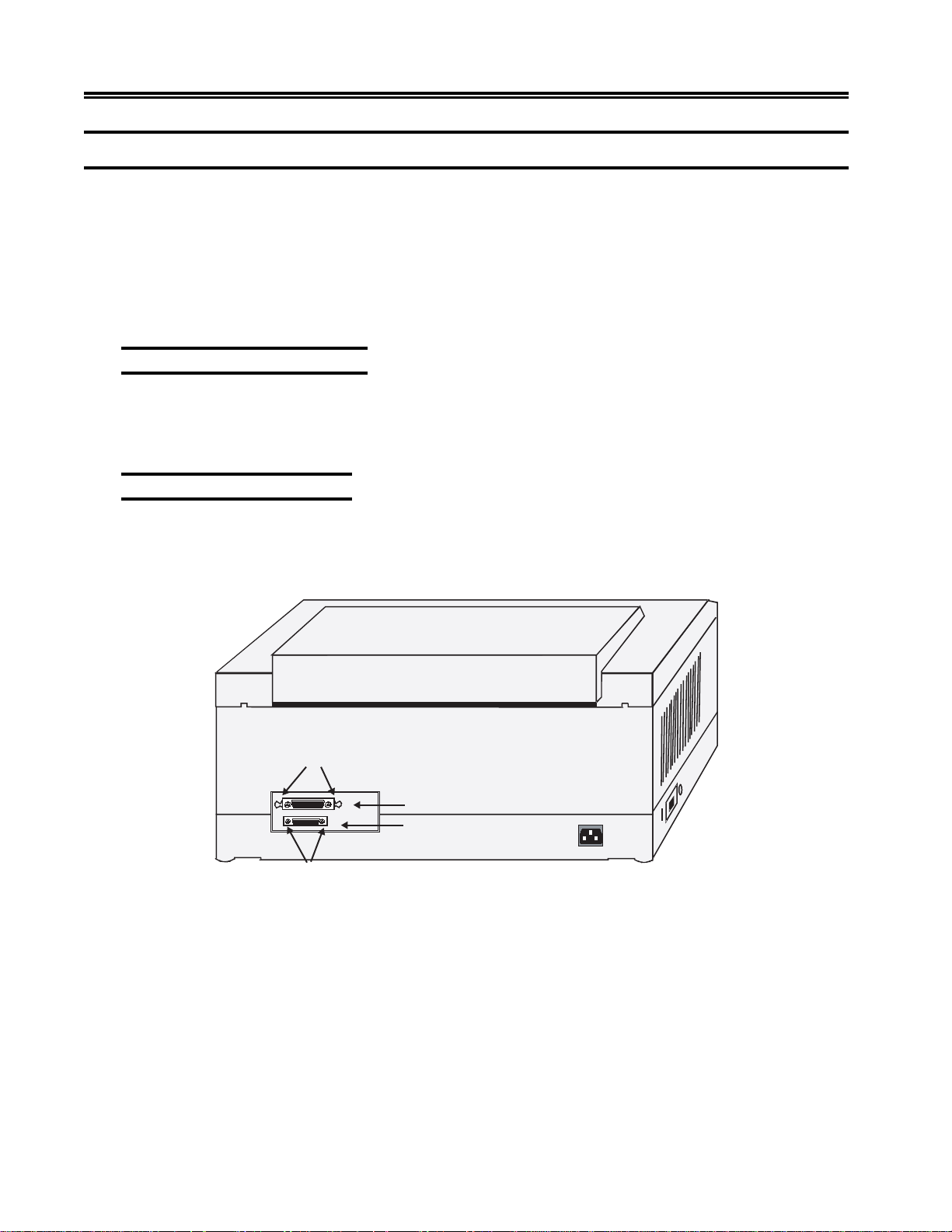
Uncoil the A C po wer cord. Plug the socket end of the power cord into the r eceptacle on
the back of the 1330 (see Figure 2-7), then plug the connector end of the power cord into
the proper A C outlet.
Power Cable Requirements
For operation at 100-120V: The power cable required for domestic units is a UL listed,
CSA certified, 18/3 AWG, type SVT or SJT cable (15-foot [4.6-meter] maximum). It is
terminated on one end by a 125V, 15A grounding type attachment connector. It is
terminated at the other end by a 125V, 15A parallel blade, grounding type attachment
plug.
For operation at 200-240V: The power cable required for domestic units is a UL listed,
CSA certified, 18/3 AWG, type SVT or SJT cable (15-foot [4.6-meter] maximum). It is
terminated on one end by a 250V, 15A grounding type attachment plug body. It is
terminated at the other end by a 250V, 15A tandem blade, grounding type attachment
connector.
The power cable required for international units is an 18/3 AWG, type SJT cable (15foot [4.6-meter] maximum). It is terminated on one end by a 250V, 15A grounding type
attachment plug body. It is terminated at the other end by a 250V, 15A grounding type
cord connector. The cord set is marked HAR to signify appropriate safety approvals.
The installation site must provide a properly wired and grounded power outlet. Circuits
connected to air conditioners and devices that generate significant transient electrical
noise should be avoided.
Electrostatic discharge in the vicinity of the unit should be minimized by avoiding high
resistance floor material and carpeting that does not have antistatic properties, avoiding
the use of plastic seats and covers, and avoiding lo w humidity levels. The unit should be
located away from areas that generate electromagnetic interference (for example,
2-8 701333-004
Preparing to Operate the 1330
transformers, power distribution panels, and motors). The unit should not be installed
where the atmosphere contains corrosive elements that may damage the unit.
Cable runs should avoid areas that produce electromagnetic interference (for example,
near transformers, switching equipment, power distribution panels, and under carpets
where vacuum cleaning is done). Also, heavy equipment should not be mo ved or rolled
over the cable.
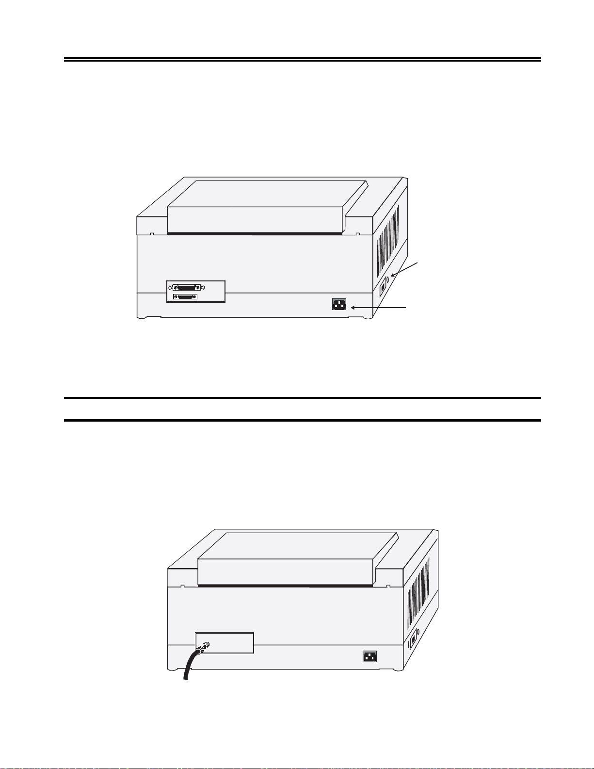
Power-On/Off
Switch
AC Power Cord
Receptacle
Figure 2-7. Installing the AC Power Cord
After installing the ribbon cartridge and connecting the 1330 to a power source, you are
ready to connect the coax cable.
Connecting the Coax Cable
Before you connect the coax data cable, make sure the Power switch is in the O (OFF)
position.
Route the coax cable to the coax connector receptacle on the back of the 1330. See
Figure 2-8. Plug the cable connector into the receptacle and turn the connector clockwise
until the slots on the side of the connector lock against the studs on the side of the
receptacle.
Figure 2-8. Connecting the Coax Cable
701333-004 2-9
Preparing to Operate the 1330
Connecting a Parallel or Serial Cable
T o comply with FCC regulations, use one of the follo wing cables:
• Parallel cable – MTX P/N 956588-001 (36-pin, 6 ft. EIA).
• RS-232 serial cable – This is available as P/N 957520-0 10 (10 feet). For other RS-232
or RS-422 applications, use locally available cables.
Before you connect the cable, make sure the Power switch is in the O (OFF) position.
Connecting a Parallel Cable
Push the male end of the parallel cable into the parallel receptacle on the back of the
1330 (see Figure 2-9). Push the wire guards, located at each end of the receptacle, in,
over the cable end, to hold the cable in place.
Connecting a Serial Cable
Loosen the screws at each end of the serial receptacle on the back of the 1330 (see Figure
2-9). Push the male end of the serial cable into the serial receptacle. Tighten the scre ws
to hold the cable in place.
Wire Guards
Parallel Receptacle
Serial Receptacle
Screws
Figure 2-9. Connecting a Parallel or Serial Cable
2-10 701333-004

Powering on the 1330
Turn the printer on by setting the Power switch to the | (ON) position (see Figure 2-7).
When the printer is powered on, B ASIC ASSURANCE TEST IN PR OGRESS will appear
in the display window . The Basic Assurance T est (B AT) tests various components of the
1330 and ensures that the printer is ready for operation. The current status of the test in
progress is displayed in the bottom row. If an error condition is encountered during the
BAT, the B A T will halt and the error message will be displayed. For a list of er ror messages
and recovery procedures, refer to Appendix A of this manual.
Note: If you have been following the pr ocedures for printer installation as presented
in this chapter, the display will indicate that there is no paper in the printer.
Continue to follow these procedures.
When the BAT is completed successfully (within a few seconds), the READY message
will appear in the display window . In 3270 mode, if communications hav e been established
with the host system, Cu will display . If communications have not been established with
the host, the display will read READY, and Cu will disappear in about 30 seconds.
Preparing to Operate the 1330
The next step is to check your forms against the 1330 forms specifications.
Forms Specifications
Before installing the forms, you should review the forms you intend to use to make sure
they meet 1330 specifications. Figures 2-10 through 2-13 show these specifications.
Specifications are given for the two types of form feed mechanism available for the
1330, the Continuous Forms module and the Forms Handler module (with both the
Document on Demand [DOD] option and Document Insertion Device [DID] option).
701333-004 2-11

Preparing to Operate the 1330
epyTeludoMABB
smroFfoepyTsuounitnoCsuounitnoCelgniS
htgneL
mumixaMni0.41ni0.41ni0.41
muminiMni0.3ni0.3ni5.7
htdiW
mumixaMni0.51ni0.51ni0.51
muminiMni0.3ni0.3ni0.3
ssenkcihTsmroF
traPelgniS
mumixaMni600.0ni600.0ni600.0
muminiMni300.0ni300.0ni300.0
suounitnoCDODDID
eludoMsmroFnoitpOnoitpO
mc6.53mc6.53mc6.53
mc6.7mc6.7mc0.91
mc1.83mc1.83mc1.83
mc6.7mc6.7mc6.7
mm51.0mm51.0mm51.0
mm80.0mm80.0mm80.0
trapitluM
elbawollAmumixaMni520.0ni520.0ni520.0
mm46.0mm46.0mm46.0
dednemmoceRmumixaMni810.0ni810.0ni810.0
mm64.0mm64.0mm64.0
trapitluMniteehShcaE
mumixaMni600.0ni600.0ni600.0
mm51.0mm51.0mm51.0
muminiMni200.0ni200.0ni200.0
mm50.0mm50.0mm50.0
straPelpitluM
*elbawollAmumixaM666
dednemmoceRmumixaM441
*thgieW
traPelgniS
**mumixaMbl04bl04bl04
muminiMbl51bl51bl51
trapitluMniteehShcaE
**mumixaMbl04bl04bl04
muminiMbl21bl21bl21
*Specifications are applicable in coordination with forms thickness specifications.
**Forms should be tested by the customer for acceptability.
Figure 2-10. Forms Specifications - Ph ysical Requirements
2-12 701333-004

Preparing to Operate the 1330
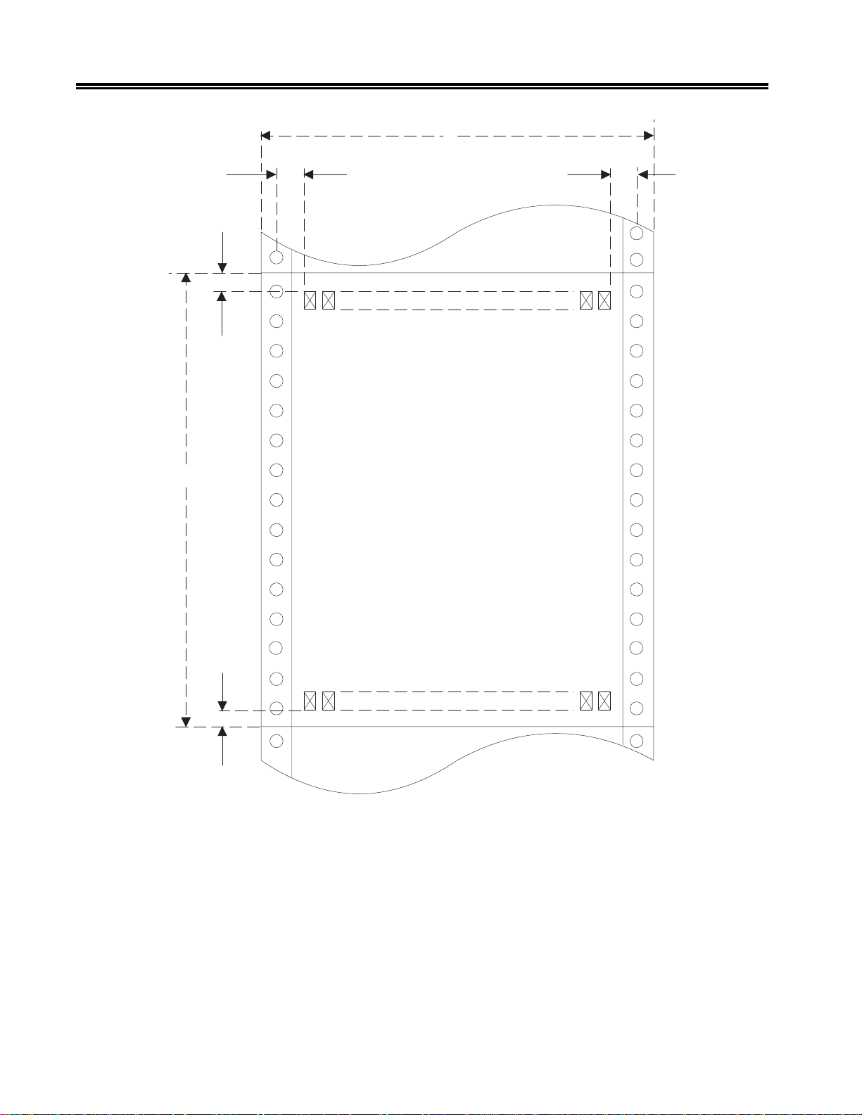
suounitnoCDODDID
eludoMsmroFnoitpOnoitpO
)A(htdiWsmroF
mumixaMni0.51ni0.51ni0.51
mc1.83mc1.83mc1.83
muminiMni0.3ni0.3ni0.3
mc6.7mc6.7mc6.7
)B(htgneLsmroF
mumixaMni0.41ni0.41ni0.41
mc6.53mc6.53mc6.53
muminiMni0.3ni0.3ni5.7
mc6.7mc6.7mc0.91
)C(noitisoPtnirPtsriF
mumixaMni56.0ni56.0ni56.0
mc7.1mc7.1mc7.1
muminiMni51.0ni51.0ni51.0
mc83.0mc83.0mc83.0
)D(noitisoPtnirPtsaL
muminiMni52.0ni52.0ni52.0
mc46.0mc46.0mc46.0
)E(eniLtnirPtsriFni052.0ni526.0ni005.0
mc46.0mc95.1mc72.1
)F(eniLtnirPtsaLni52.0ni52.0ni52.0
mc46.0mc46.0mc46.0
Figure 2-11. Forms Specifications - Print P ositioning
Refer to Figures 2-12 and 2-14 for an explanation of the meaning of the letters A through F.
701333-004 2-13
Preparing to Operate the 1330
A
C
E
B
D
F
Figure 2-12. Print Positioning - Continuous Forms
2-14 701333-004
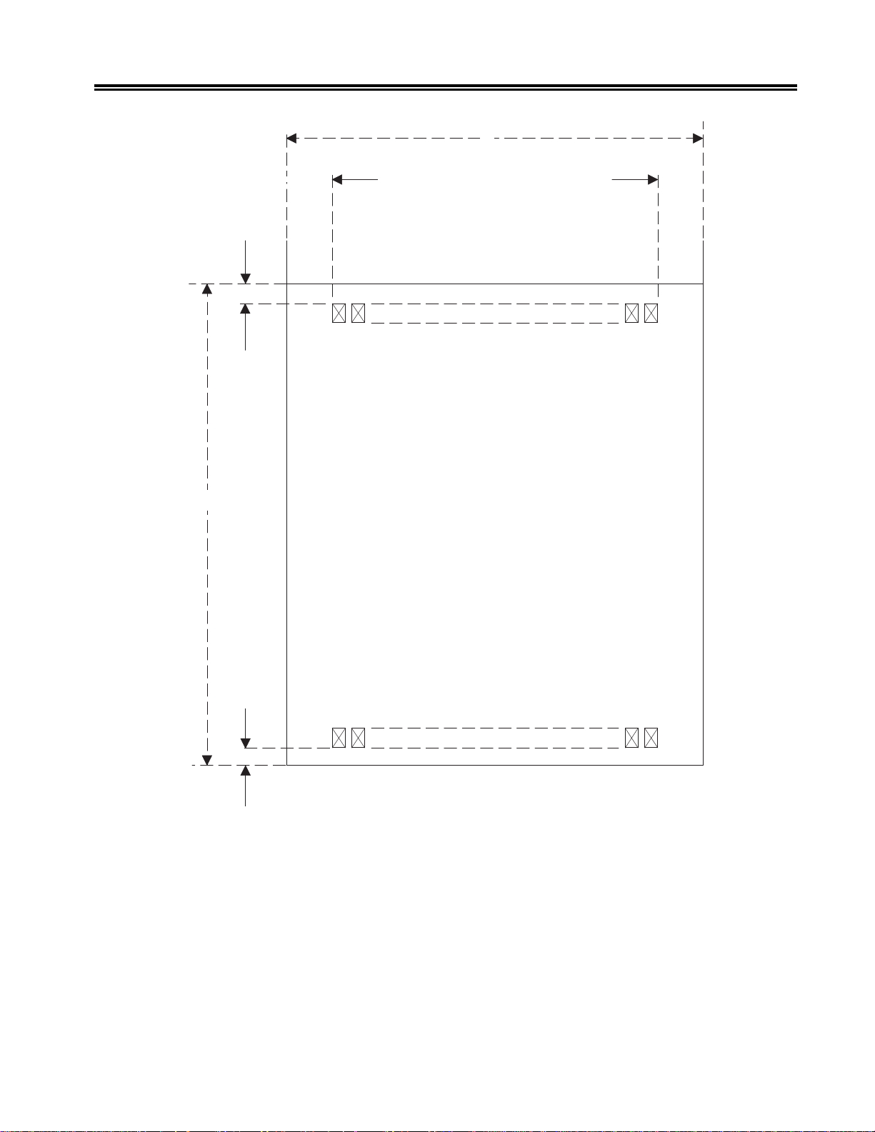
Preparing to Operate the 1330
A
C
E
B
D
F
Figure 2-13. Print Positioning - Single Part F orms
701333-004 2-15

Preparing to Operate the 1330
Review the following points carefully to ensure that your forms are appropriate for use
in the 1330.
1. Except for horizontal dimensions of the first print position specif ied in Figures 2-12
and 2-13, no printing should occur within 0.25 inch (0.6 cm) of any edge, perforation,
or fold.
2. Printing m ust not occur across any holes, perforations, or edges of the forms, nor
should printing occur directly on the platen.
3. Continuous card stock forms are not recommended.
4. Nar row width forms (less than 8.0 inches [20.3 cm]) contribute to instability of
stacking and may require operator attention. W ider base forms are recommended.
5. The minimum single part forms thickness is 0.003 inch (0.08 mm). The maximum
single part forms thickness is 0.006 inch (0.15 mm).
6. The maximum allowable multiple part forms thickness is 0.025 inch (0.64 mm).
The maximum recommended multipart forms thickness is 0.018 inch (0.46 mm).
The minimum thickness for any sheet in multipart forms is 0.002 inch (0.05 mm)
(carbon excluded). The maximum thickness for any sheet in multipart forms is 0.006
inch (0.15 mm).
7. Up to six-part continuous part forms (original plus fi ve copies) can be used. Howeve r,
for optimum feeding, registration, and print quality, a maximum of four parts is
recommended. All multipart forms should be tested by the customer prior to use for
satisfactory feeding, registration, and print quality .
8. Carbon forms are recommended for multipart continuous forms. Carbonless (ink
impregnated) forms can be used but may result in less legible print than carbon
paper.
9. No hard or metallic fasteners are permitted.
10. Gluing is the recommended method of fastening forms. The gluing must be adequate
to prevent separation or shifting of the forms as they are fed through the printer .
11. Crimping is not recommended. However, if crimping is used, the crimps must be
located no more than 2 inches (5.1 cm) apart along the margins of the forms length.
12. Partial forms separation is not permitted.
13. Translucent or thin forms may cause the paper motion detector to give f alse readings.
The paper motion detector can be disabled, if required, to allow the use of these
forms (see Chapter 4).
Next is the procedure for using the Continuous Forms module.
2-16 701333-004
 Loading...