


Viking Pump TSM685.1 User Manual
Electronic copies of the most current TSM issue can be found on the Viking Pump website at www.vikingpump.com
TECHNICAL SERVICE MANUAL
CONTENTS
Introduction . . . . . . . . . . . . . . . . . . . . . . . 1
Safety Information. . . . . . . . . . . . . . . . . . . . 2
Special Information . . . . . . . . . . . . . . . . . . . 3
Maintenance . . . . . . . . . . . . . . . . . . . . . . 3
Disassembly of Pump. . . . . . . . . . . . . . . . . . 4
Disassembly of Couplings . . . . . . . . . . . . . . . 7
Disassembly / Assembly Bearing Housing . . . . . . . 9
Installation of Bushings . . . . . . . . . . . . . . . . . 9
Assembly of Pump . . . . . . . . . . . . . . . . . . . 9
Pump Rotation . . . . . . . . . . . . . . . . . . . . .10
Assembly of Couplings . . . . . . . . . . . . . . . . . 11
Adjusting End Clearance . . . . . . . . . . . . . . . .13
Pressure Relief Valve Instructions . . . . . . . . . . .13
Troubleshooting. . . . . . . . . . . . . . . . . . . . 15
SECTION TSM
PAGE
ISSUE
SERIES 855
Sizes GS, GG, HJ, HL
MODEL NUMBER CHART
UNMOUNTED PUMPS UNITS
GS-855U, GS-855M,
GG-855U, GG-855M
HJ-855U, HJ-855M
HL-855U, HL-855M
Units are designated by the unmounted pump model numbers
followed by the magnetic coupling
size and a letter indicating drive
style.
(Example: GG-855MA MD2 A9 M )
D = Direct Drive
M = Motor Mount
B = Bearing Carrier
R = Viking Reducer Drive
P = Commercial Reducer Drive
See Page 4 for complete description of
the model number
TABLE 1
685.1
1 OF 16
F
WARNING!
Persons with surgical implants of a metallic
or electronic nature should avoid working on
pump – especially the inner magnet assembly.
INTRODUCTION
The illustrations used in this manual are for identification
purposes only and cannot be used for ordering parts. Obtain
a parts list from the factory or a Viking® representative.
Always give the complete name of the part, part number and
material with the model number and serial number of the
pump when ordering repair parts. The unmounted pump or
pump unit model number and serial number can be found on
the nameplate secured to the pump.
This manual deals only with Series 855 magnetic drive pumps.
Refer to Figures 1 through 34 for general configuration and
nomenclature used in this manual. Pump specifications and
recommendations are listed in Catalog Section 685.
In the Viking model number system, the basic size letters
are combined with the series number (855) indicating basic
pump construction material.
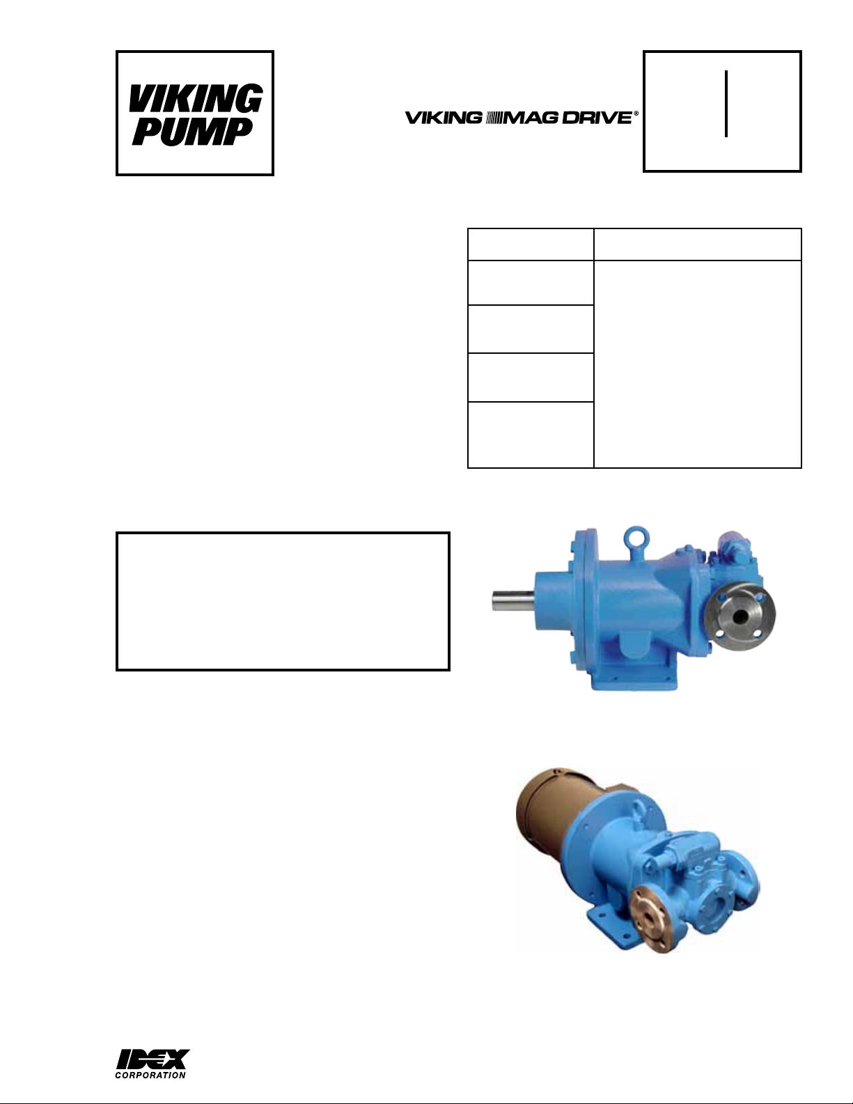
FIGURE 1
GS,GG SERIES 855MA MD2-A9 B
Pump with Bearing Carrier
FIGURE 2
HJ-HL SERIES 855MB MD2-B M
Pump with Motor Directly Mounted to the Bracket
VIKING PUMP, INC. • A Unit of IDEX Corporation • Cedar Falls, IA 50613 USAVIKING PUMP, INC. • A Unit of IDEX Corporation • Cedar Falls, IA 50613 USA
SAFETY INFORMATION AND INSTRUCTIONS
IMPROPER INSTALLATION, OPERATION OR MAINTENANCE OF PUMP MAY CAUSE SERIOUS INJURY
OR DEATH AND/OR RESULT IN DAMAGE TO PUMP AND/OR OTHER EQUIPMENT. VIKING’S WARRANTY
DOES NOT COVER FAILURE DUE TO IMPROPER INSTALLATION, OPERATION OR MAINTENANCE.
THIS INFORMATION MUST BE FULLY READ BEFORE BEGINNING INSTALLATION, OPERATION OR
MAINTENANCE OF PUMP AND MUST BE KEPT WITH PUMP. PUMP MUST BE INSTALLED, OPERATED
AND MAINTAINED ONLY BY SUITABLY TRAINED AND QUALIFIED PERSONS.
THE FOLLOWING SAFETY INSTRUCTIONS MUST BE FOLLOWED AND ADHERED TO AT ALL TIMES.
Symbol
Legend :
!
!
!
!
!
WARNING
!
WARNING
Danger - Failure to follow the indicated
instruction may result in serious injury
!
or death.
BEFORE opening any liquid chamber (pumping
chamber, reservoir, relief valve adjusting cap fitting,
etc.) be sure that :
● Any pressure in the chamber has been completely
vented through the suction or discharge lines or
other appropriate openings or connections.
● The pump drive system means (motor, turbine,
engine, etc.) has been “locked out” or otherwise
been made non-operational so that it cannot be
started while work is being done on the pump.
● You know what material the pump has been
handling, have obtained a material safety data
sheet (MSDS) for the material, and understand
and follow all precautions appropriate for the safe
handling of the material.
BEFORE operating the pump, be sure all drive guards
are in place.
DO NOT operate pump if the suction or discharge
piping is not connected.
DO NOT place fingers into the pumping chamber or
its connection ports or into any part of the drive train
if there is any possibility of the pump shafts being
rotated.
DO NOT exceed the pumps rated pressure, speed, and
temperature, or change the system/duty parameters
from those the pump was originally supplied, without
confirming its suitability for the new service.
BEFORE operating the pump, be sure that:
● It is clean and free from debris
● all valves in the suction and discharge pipelines
are fully opened.
● All piping connected to the pump is fully supported
and correctly aligned with the pump.
● Pump rotation is correct for the desired direction
of flow.
WARNING
WARNING
!
WARNING
!
!
!
WARNING
!
WARNING
Warning - In addition to possible serious
injury or death, failure to follow the
indicated instruction may cause damage
to pump and/or other equipment.
INSTALL pressure gauges/sensors next to the
pump suction and discharge connections to monitor
pressures.
USE extreme caution when lifting the pump. Suitable
lifting devices should be used when appropriate. Lifting
eyes installed on the pump must be used only to lift
the pump, not the pump with drive and/or base plate.
If the pump is mounted on a base plate, the base plate
must be used for all lifting purposes. If slings are used
for lifting, they must be safely and securely attached.
For weight of the pump alone (which does not include
the drive and/or base plate) refer to the Viking Pump
product catalog.
DO NOT attempt to dismantle a pressure relief valve
that has not had the spring pressure relieved or is
mounted on a pump that is operating.
AVOID contact with hot areas of the pump and/or
drive. Certain operating conditions, temperature
control devices (jackets, heat-tracing, etc.), improper
installation, improper operation, and improper
maintenance can all cause high temperatures on the
pump and/or drive.
THE PUMP must be provided with pressure protection.
This may be provided through a relief valve mounted
directly on the pump, an in-line pressure relief valve,
a torque limiting device, or a rupture disk. If pump
rotation may be reversed during operation, pressure
protection must be provided on both sides of pump.
Relief valve adjusting screw caps must always point
towards suction side of the pump. If pump rotation is
reversed, position of the relief valve must be changed.
Pressure relief valves cannot be used to control pump
flow or regulate discharge pressure. For additional
information, refer to Viking Pump’s Technical Service
Manual TSM 000 and Engineering Service Bulletin
ESB-31.
THE PUMP must be installed in a matter that allows
safe access for routine maintenance and for inspection
during operation to check for leakage and monitor
pump operation.
SECTION TSM 685.1 ISSUE G PAGE 2 OF 16
SPECIAL INFORMATION
DANGER !
For additional information on pressure relief valves, refer to
Technical Service Manual TSM000 and Engineering Service
Bulletin ESB-31.
Before opening any Viking pump liquid chamber (pumping chamber, reservoir, relief valve
adjusting cap fitting etc.) Be sure:
1. That any pressure in the chamber has been
completely vented through the suction or
discharge lines or other appropriate openings
or connections.
2. That the driving means (motor, turbine,
engine, etc.) has been “locked out” or made
non- operational so that it cannot be started
while work is being done on pump.
3. That you know what liquid the pump has been
handling and the precautions necessary to
safely handle the liquid. Obtain a material
safety data sheet (MSDS) for the liquid to be
sure these precautions are understood.
Failure to follow above listed precautionary measures may result in serious injury or
death.
ROTATION: Viking Mag Drive® pumps are designed to run
either direction. See PUMP ROTATION, page 10.
PRESSURE RELIEF VALVES:
1. Viking pumps are positive displacement pumps and must
be provided with some sort of pressure protection. This
may be a relief valve mounted directly on the pump, an
inline pressure relief valve, a torque limiting device or a
rupture disk. Do not rely on decoupling of magnets for
protection from over pressure; this may result in damage
to the magnets, pump, or other equipment.
2. Relief valves are mounted as standard on the casing of
GS, GG, HJ, and HL size pumps.
3. If the pump rotation is to be reversed during operation,
pressure protection must be provided on both sides of
the pump.
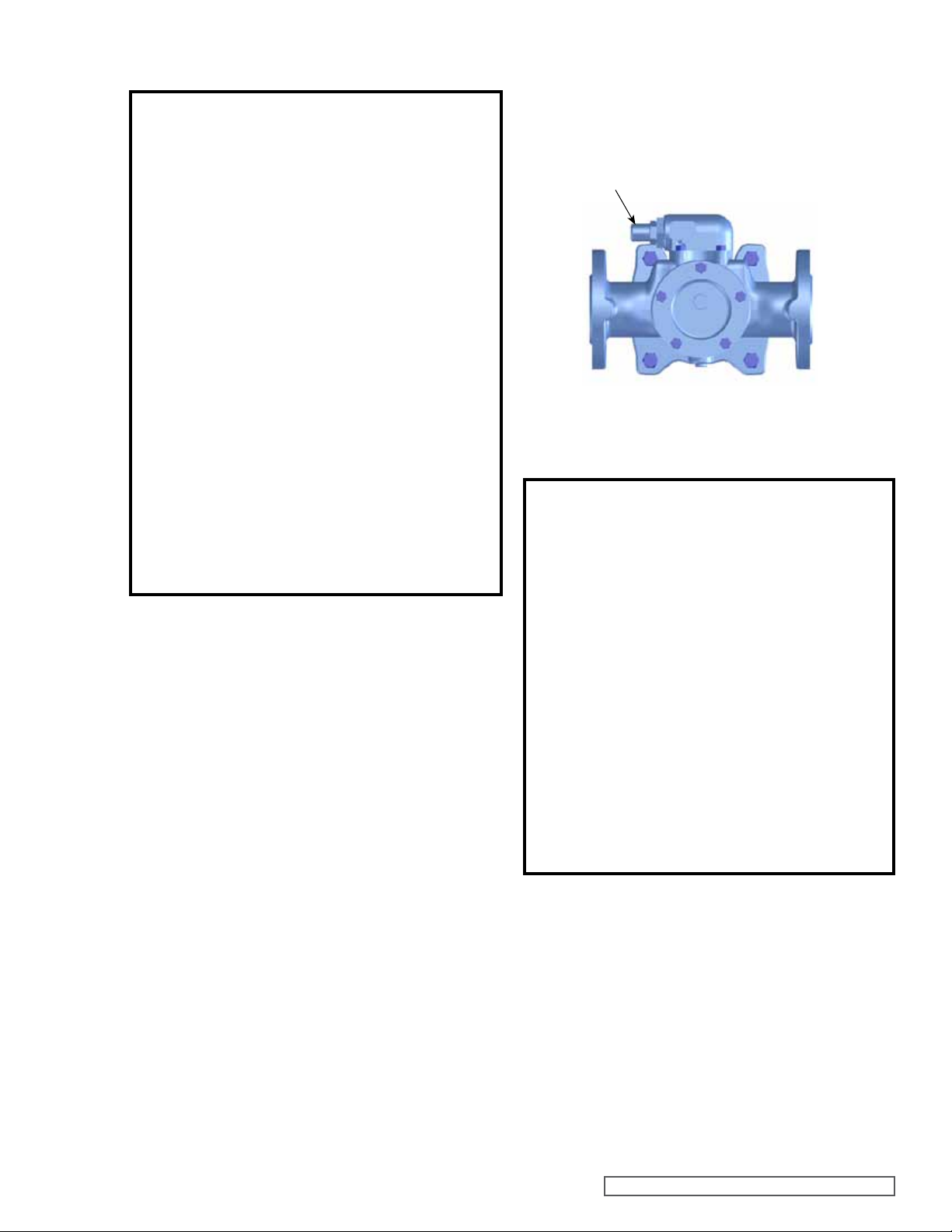
4. The relief valve adjusting screw cap must always point
towards the suction side of the pump. See Figure 3. If
the pump rotation is reversed, remove the pressure
relief valve and turn end for end (see PUMP ROTATION,
page 10 first for additional steps required for proper
operation).
5. Pressure relief valves cannot be used to control pump
flow or regulate discharge pressure.
RELIEF VALVE ADJUSTING
SCREW CAP
SUCTION
FIGURE 3
RELIEF VALVE POSITION
DISCHARGE
CAUTION !
Rare earth magnets used in couplings have
extremely strong magnetic fields capable of
changing performance or damaging items
such as the following:
Pacemakers
Metal Implants
Watches
Computers & disks
Credit Cards
Completely assembled magnetic couplings
will not affect items listed above – only disassembled components.
There are no known harmful effects of these
magnetic fields on the human body.
MAINTENANCE
Series 855 pumps are designed for long, trouble-free service
life under a wide variety of application conditions with a
minimum of maintenance. The points listed below will help
provide long service life.
CLEANING PUMP:
Keep the pump as clean as possible. This will facilitate
inspection, adjustment and repair work.
SECTION TSM 685.1 ISSUE G PAGE 3 OF 16
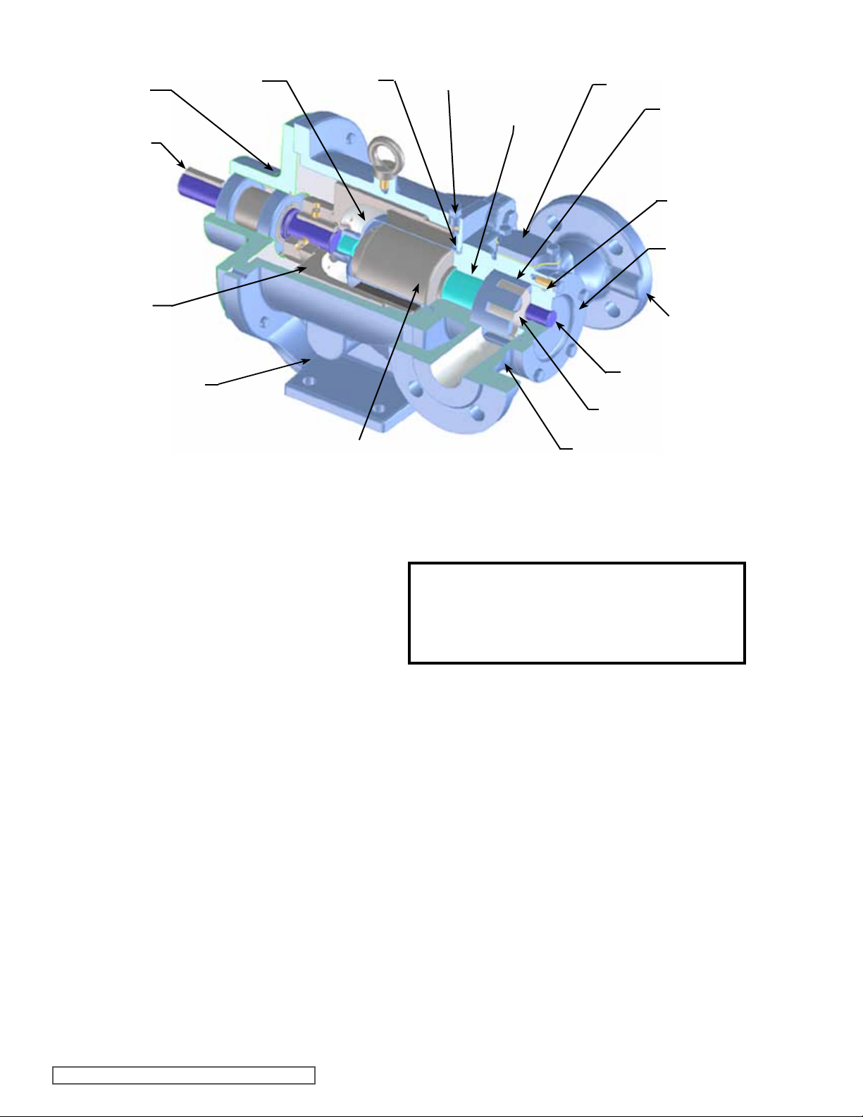
BEARING
CARRIER
ASSEMBLY
(Optional)
SHAFT
CANISTER
CANISTER
O-RING
TEMPERATURE
PROBE HOLE
CASING
BUSHING
RELIEF VALVE
(shown with optional
RV coverplate)
ROTOR
HEAD
GASKET
SEAL
HEAD
OUTER
MAGNET
ASSEMBLY
BRACKET
INNER MAGNET
ASSEMBLY
CASING
IDLER PIN
IDLER
CUTAWAY VIEW MAG DRIVE PUMP, MODEL HL855M MD2-B B ILLUSTRATED. (TYPICAL OF GG-HL SIZES)
FIGURE 4
MAINTENANCE (Cont.)
STORAGE:
If the pump and coupling are to be stored, drain the pump
and pour non-detergent SAE 30-weight oil into the pump port.
Apply grease to the pump or the coupling shaft extension, if
PUMP DISASSEMBLY
WARNING!
Refer to DANGER & CAUTION listed on page 2
before proceeding.
present or accessible.
Viking suggests rotating the pump shaft every 30 days to
circulate the oil in the pump. The coupling should be stored
in a dry area.
NOTE: If the liquid to be pumped reacts with oil, use an
acceptable alternate.
SUGGESTED REPAIR TOOLS:
The following tools are required to properly repair Series 855
pumps. These tools are in addition to standard mechanics’
tools such as open-end wrenches, pliers, screwdrivers, etc.
Most of the items can be obtained from an industrial supply
house.
1. Soft face hammer
2. Metric Allen wrenches (for set screws)
3. Torque Wrench with a locknut socket
4. External snap ring pliers - 2-810-029-375
5. Internal snap ring pliers - 2- 810-047-999
6. Arbor press
7. Brass bar
8. Hook style spanner wrench
1. To drain the liquid being pumped, remove the two (2)
drain plugs located in the bottom of the casing. Once the
liquid has drained replace the plugs.
2. Refer to Figures 4, 6 & 7 for names of parts.
3. Mark the head and casing before disassembly to insure
proper reassembly.
4. To inspect the head and pin assembly and idler and
bushing assembly, remove the head capscrews.
5. Remove the head from the pump. Do not allow the idler
to fall from the idler pin. Tilt the top of the pump head
back when removing to prevent this. Avoid damaging the
head shim set since all shims are required to maintain
end clearance.
6. Remove the idler and bushing assembly. If the idler
bushing needs to be replaced, see INSTALLATION OF
BUSHINGS, page 9. If further disassembly is required,
the pump must be separated from coupling. Refer
to DISASSEMBLY OF COUPLING, page 7, before
proceeding with Step 7.
GAUGE
PORT BOSS
SECTION TSM 685.1 ISSUE G PAGE 4 OF 16
Series
GS 8 5 5 M A-MD2 A9 B
Size
(Nominal displacement)
GS
HJ
GG
HL
Material
5 = Cast Iron
Port Design and Fasteners
M= DIN and metric fasteners
U= ANSI and inch fasteners
Coupling Size - Pump Related
A size = Used on GS, GG, HJ or HL
B size = Used on HJ, HL, AS, AK or AL
C size = Used on AS, AK, AL, KE, or KKE
AS
AK
AL
KE
KKE
FIGURE 5
MODEL NUMBER SYSTEM
Drive Congurations
D = Direct drive
R = Reducer drive
B = Bearing carrier
P = Purchased reducer
Magnetic Coupling Size and
Torque Specication - Drive
Related
A 4 and 9 Ft-Lbs
B 14,32 and 50 Ft-Lbs
C 40,90, 135 and 180 Ft-Lbs
Magnetic Coupling Design
Second generation and not interchangable
with previous design.
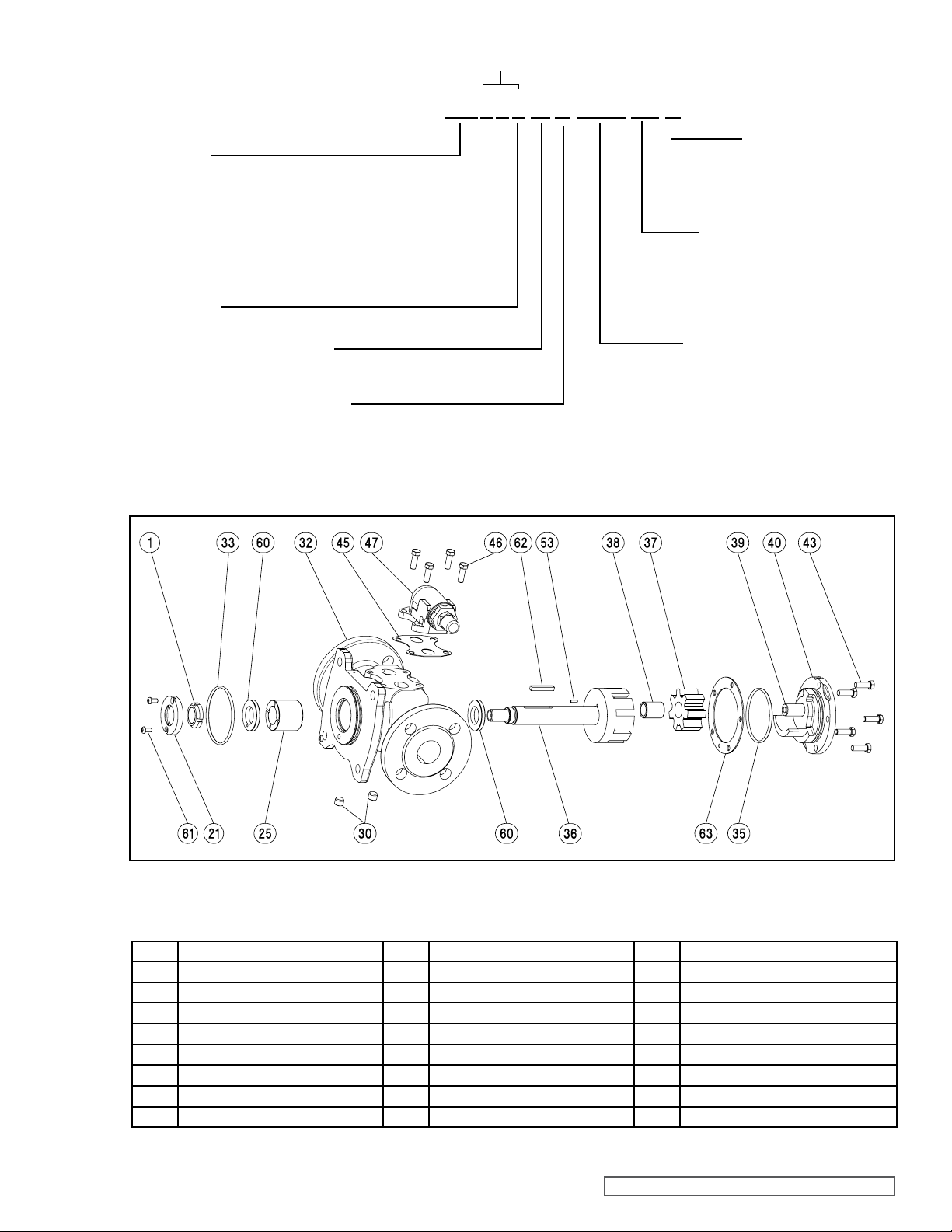
FIGURE 6
EXPLODED VIEW – SIZES GS, GG, HJ & HL MAG-DRIVE PUMPS
ITEM NAME OF PART ITEM NAME OF PART ITEM NAME OF PART
1 Locknut 37 Idler 53 Locating Pin
21 Set Collar 38 Idler Bushing 60 Thrust Washer (2 Req’d)
25 Casing Bushing 39 Idler Pin 61 Machine Screws (2 Req’d)
30 Pipe Plug (2 Req’d) 40 Head and Idler Pin Assembly 62 Drive Key
32 Casing and Bushing Assembly 43 Capscrews for Head 63 Shims for Head (metal)
33 Casing Stem O-ring 45 Relief Valve Gasket
35 Head O-ring 46 Capscrews for Relief Valve
36 Rotor and Shaft Assembly 47 Relief Valve
TABLE 2
SECTION TSM 685.1 ISSUE G PAGE 5 OF 16