

Viking Pump TSM153 User Manual
Electronic copies of the most current TSM issue can be found on the Viking Pump website at www.vikingpump.com
TECHNICAL SERVICE MANUAL
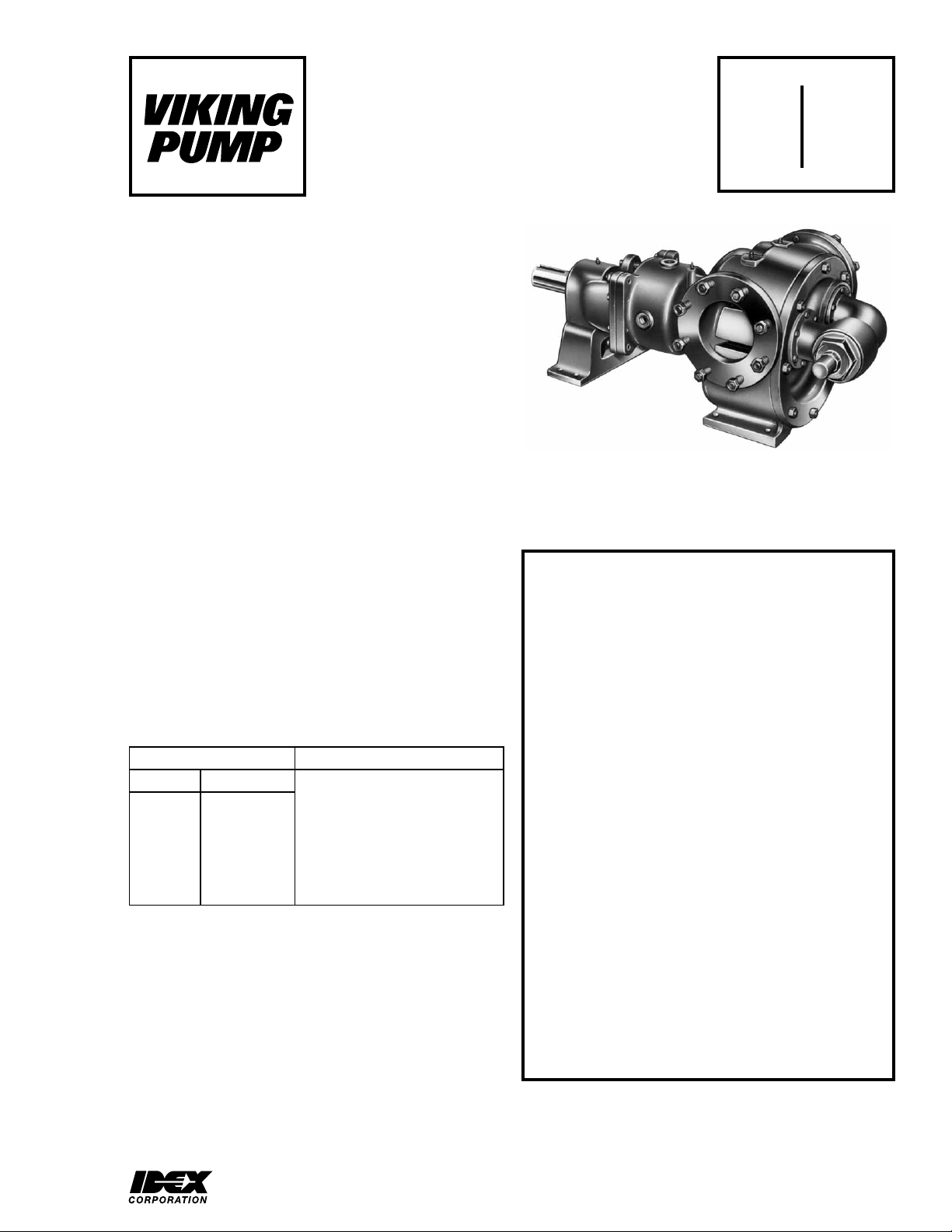
HEAVY-DUTY STEEL EXTERNAL PUMPS
CONTENTS
Introduction . . . . . . . . . . . . . . . . . . . . . . . 1
Special Information . . . . . . . . . . . . . . . . . . . 1
Maintenance . . . . . . . . . . . . . . . . . . . . . . 2
Packed Pumps . . . . . . . . . . . . . . . . . . . . . 4
Mechanical Seal Pumps . . . . . . . . . . . . . . . . 8
Optional PTFE Seal. . . . . . . . . . . . . . . . . . .13
Thrust Bearing Adjustment . . . . . . . . . . . . . . .14
Installation of Carbon Graphite Bushings . . . . . . . .14
Pressure Relief Valve Instructions . . . . . . . . . . 15
INTRODUCTION
The illustrations used in this manual are for identification
purposes only and cannot be used for ordering parts. Obtain a
parts list from the factory or a Viking® representative. Always
give complete name of part, part number and material with
model number and serial number of pump when ordering
repair parts. The unmounted pump or pump unit model
number and serial number are on the nameplate.
In the Viking model number system, basic size letters are
combined with series number (333 and 4333) are used to
indicate either an unmounted pump or mounted pump unit.
SECTION TSM 153
PAGE 1 Of 16
SERIES 333 AND 4333
ISSUE D
SIZES N AND R
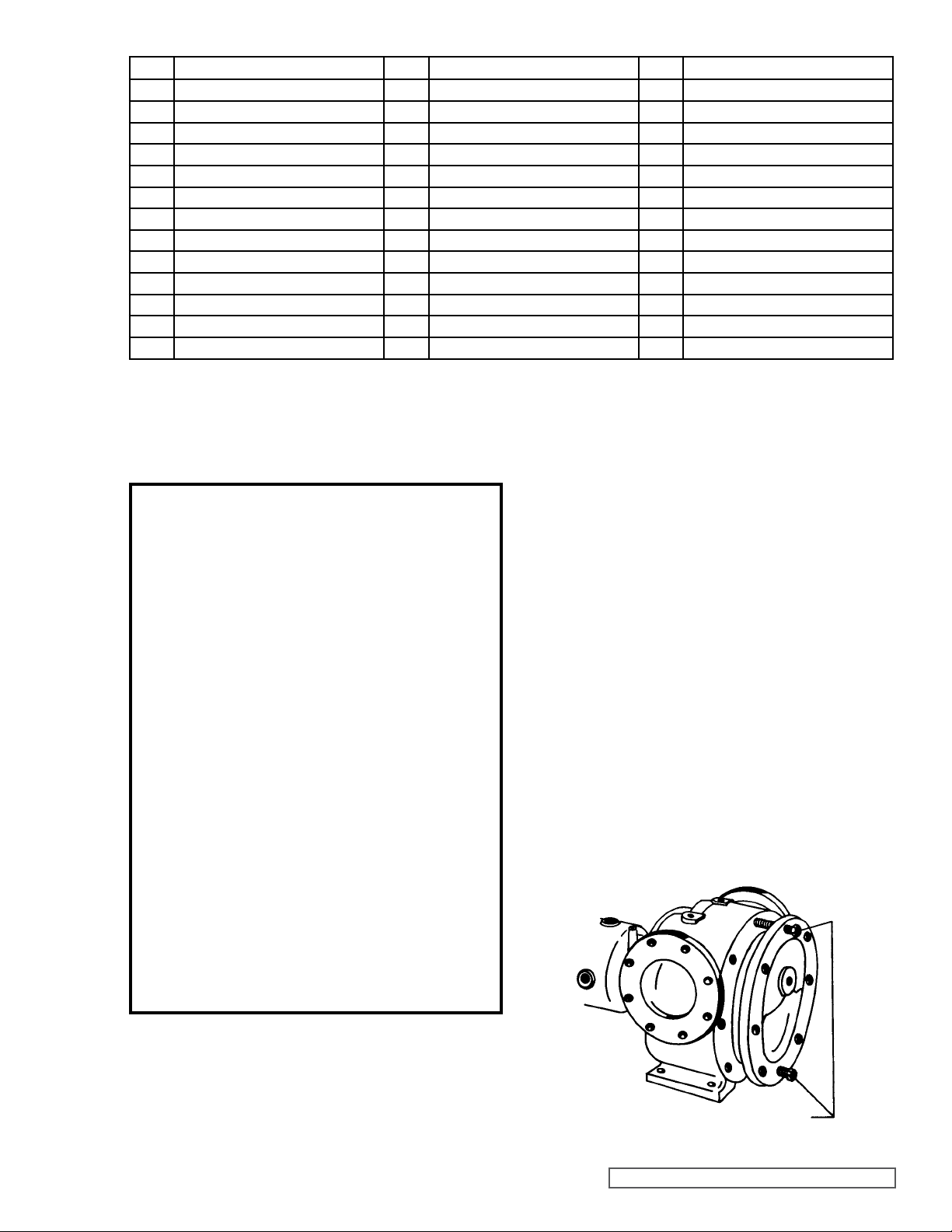
FIGURE 1
R333 SIZE SHOWN
SPECIAL INFORMATION
DANGER !
Before opening any Viking pump liquid
chamber (pumping chamber, reservoir,
relief valve adjusting cap fitting, etc.)
Be sure:
Model Chart Number
UNMOUNTED PUMP UNITS
PACKED MECH. SEAL
N333 N4333
R333 R4333
This manual deals only with Series 333 and 4333 Heavy Duty
Steel External Pumps. Refer to Figures 1 through 20 for
general configuration and nomenclature used in this manual.
Pump specifications and recommendations are listed in
Catalog Section 153, Series 333 and 4333 Heavy Duty Steel
External Pumps.
Units are designated by the
unmounted pump model
numbers followed by a letter(s)
indicating drive style.
P = Commercial Speed Reducer
1. That any pressure in the chamber has
been completely vented through the
suction or discharge lines or other
appropriate openings or connections.
2. That the driving means (motor,
turbine, engine, etc.) has been “locked
out” or made non-operational so that
it cannot be started while work is
being done on pump.
3. That you know what liquid the
pump has been handling and the
precautions necessary to safely
handle the liquid. Obtain a material
safety data sheet (MSDS) for the
liquid to be sure these precautions
are understood.
Failure to follow above listed
precautionary measures may result in
serious injury or death.
VIKING PUMP, INC. • A Unit of IDEX Corporation • Cedar Falls, IA 50613 USA
SAFETY INFORMATION AND INSTRUCTIONS
IMPROPER INSTALLATION, OPERATION OR MAINTENANCE OF PUMP MAY CAUSE SERIOUS INJURY
OR DEATH AND/OR RESULT IN DAMAGE TO PUMP AND/OR OTHER EQUIPMENT. VIKING’S WARRANTY
DOES NOT COVER FAILURE DUE TO IMPROPER INSTALLATION, OPERATION OR MAINTENANCE.
THIS INFORMATION MUST BE FULLY READ BEFORE BEGINNING INSTALLATION, OPERATION OR
MAINTENANCE OF PUMP AND MUST BE KEPT WITH PUMP. PUMP MUST BE INSTALLED, OPERATED
AND MAINTAINED ONLY BY SUITABLY TRAINED AND QUALIFIED PERSONS.
THE FOLLOWING SAFETY INSTRUCTIONS MUST BE FOLLOWED AND ADHERED TO AT ALL TIMES.
Symbol
Legend :
!
!
!
!
!
WARNING
!
WARNING
Danger - Failure to follow the indicated
instruction may result in serious injury
!
or death.
BEFORE opening any liquid chamber (pumping
chamber, reservoir, relief valve adjusting cap fitting,
etc.) be sure that :
● Any pressure in the chamber has been completely
vented through the suction or discharge lines or
other appropriate openings or connections.
● The pump drive system means (motor, turbine,
engine, etc.) has been “locked out” or otherwise
been made non-operational so that it cannot be
started while work is being done on the pump.
● You know what material the pump has been
handling, have obtained a material safety data
sheet (MSDS) for the material, and understand
and follow all precautions appropriate for the safe
handling of the material.
BEFORE operating the pump, be sure all drive guards
are in place.
DO NOT operate pump if the suction or discharge
piping is not connected.
DO NOT place fingers into the pumping chamber or
its connection ports or into any part of the drive train
if there is any possibility of the pump shafts being
rotated.
DO NOT exceed the pumps rated pressure, speed, and
temperature, or change the system/duty parameters
from those the pump was originally supplied, without
confirming its suitability for the new service.
BEFORE operating the pump, be sure that:
● It is clean and free from debris
● all valves in the suction and discharge pipelines
are fully opened.
● All piping connected to the pump is fully supported
and correctly aligned with the pump.
● Pump rotation is correct for the desired direction
of flow.
WARNING
WARNING
!
WARNING
!
!
!
WARNING
!
WARNING
Warning - In addition to possible serious
injury or death, failure to follow the
indicated instruction may cause damage
to pump and/or other equipment.
INSTALL pressure gauges/sensors next to the
pump suction and discharge connections to monitor
pressures.
USE extreme caution when lifting the pump. Suitable
lifting devices should be used when appropriate. Lifting
eyes installed on the pump must be used only to lift
the pump, not the pump with drive and/or base plate.
If the pump is mounted on a base plate, the base plate
must be used for all lifting purposes. If slings are used
for lifting, they must be safely and securely attached.
For weight of the pump alone (which does not include
the drive and/or base plate) refer to the Viking Pump
product catalog.
DO NOT attempt to dismantle a pressure relief valve
that has not had the spring pressure relieved or is
mounted on a pump that is operating.
AVOID contact with hot areas of the pump and/or
drive. Certain operating conditions, temperature
control devices (jackets, heat-tracing, etc.), improper
installation, improper operation, and improper
maintenance can all cause high temperatures on the
pump and/or drive.
THE PUMP must be provided with pressure protection.
This may be provided through a relief valve mounted
directly on the pump, an in-line pressure relief valve,
a torque limiting device, or a rupture disk. If pump
rotation may be reversed during operation, pressure
protection must be provided on both sides of pump.
Relief valve adjusting screw caps must always point
towards suction side of the pump. If pump rotation is
reversed, position of the relief valve must be changed.
Pressure relief valves cannot be used to control pump
flow or regulate discharge pressure. For additional
information, refer to Viking Pump’s Technical Service
Manual TSM 000 and Engineering Service Bulletin
ESB-31.
THE PUMP must be installed in a matter that allows
safe access for routine maintenance and for inspection
during operation to check for leakage and monitor
pump operation.
SECTION TSM 153 ISSUE D PAGE 2 OF 16
SPECIAL INFORMATION
ROTATION: Viking pumps operate equally well in a clockwise
or counterclockwise rotation. Shaft rotation determines which
port is suction and which is discharge. Port in area where
pumping elements (gear teeth) come out of mesh is suction
port.
FLUSH LINES: are standard equipment and must be hooked
up properly. Packed pumps have a flush connection from
packing chamber to suction port. Mechanical seal pumps
have a flush connection from seal chamber to discharge port.
If pump rotation is reversed be sure flush connections are
hooked up to the suction or discharge port as noted above
to avoid excessive leakage or damage to pump. If pump
is handling heated product be sure flush line is insulated to
assure continued flow.
Jacketed head (R only, optional on N size) and rotor bearing
sleeve provide large chambers at both ends of pumping
chamber for temperature control of product in pump. These
features do not alter basic steps in disassembly and assembly
of your pump.
PRESSURE RELIEF VALVES:
1. Viking pumps are positive placement pumps and must
be provided with some sort of pressure protection. This
may be a relief valve mounted directly on the pump, an
inline pressure relief valve, a torque limiting device or a
rupture disk.
2. There are relief valve options available on these pumps.
Options include a jacketed relief valve. Pumps equipped
with a jacketed head plate are generally not available
with a relief valve.
3. If pump rotation is to be reversed during operation,
pressure protection must be provided on both sides of
pump.
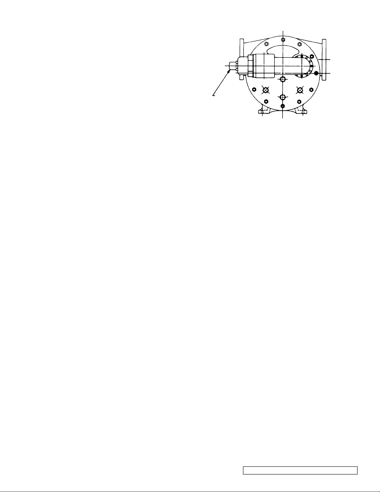
4. Relief valve adjusting screw cap must always point
towards suction side of pump. If pump rotation is
reversed, remove pressure relief valve and turn end for
end. Refer to Figures 1 and 2.
5. Pressure relief valves cannot be used to control pump
flow or regulate discharge pressure.
For additional information on pressure relief valves, refer
to Technical Service Manual TSM000 and Engineering
Service Bulletin ESB-31.
SPECIAL MECHANICAL SEALS: can be installed in a
modified stuffing box.
Extra care must be taken in repair of pumps with mechanical
seals. Read and follow all special information supplied with
the pump.
MAINTENANCE
Series 333 and 4333 pumps are designed for long trouble
free life under a wide variety of application conditions with a
minimum of maintenance. The points listed below will help
provide long service life.
INLET
OR
SUCTION
RELIEF
VALV E
ADJUSTING
SCREW
OUTLET
OR
SUCTION
FIGURE 2
LUBRICATION: External lubrication must be applied slowly
with a handgun to all lubrication fittings every 500 hours of
operation with multi-purpose grease, NLGI # 2. Do not overgrease. Applications involving very high or low temperatures
will require other types of lubrication. Refer to Engineering
Service Bulletin ESB-515. Consult factory with specific
lubrication questions.
PACKING ADJUSTMENT: New packed pumps require initial
packing adjustment to control leakage as packing “runs in”.
Make initial adjustments carefully and do not over-tighten
packing gland. After initial adjustment, inspection will reveal
need for packing gland adjustment or packing replacement.
Refer to instructions under DISASSEMBLY, page 5, and
Assembly, page 7, regarding repacking pump.
CLEANING PUMP: Keep pump as clean as possible. This
will facilitate inspection; adjustment and repair work and help
prevent overlooking a dirt covered grease fitting.
STORAGE: If pump is to be stored, or not used for six
months or more, pump must be drained and a light coat
of non-detergent SAE 30 weight oil must be applied to all
internal pump parts. Lubricate fittings and apply grease to
pump shaft extension. Viking suggests rotating pump shaft
by hand one complete revolution every 30 days to circulate
the oil.
SUGGESTED REPAIR TOOLS: The following tools must
be available to properly repair Series 333 and 4333 pumps.
These tools are in addition to standard mechanics’ tools such
as open end wrenches, pliers, screwdrivers etc. Most of the
items can be obtained from an industrial supply house.
1. Soft Headed Hammer
2. Allen Wrenches (some mechanical seals and set
collars)
3. Packing hooks, flexible (packed pumps)
Large for 0.375 inch and up cross section packing
4. Mechanical seal installation sleeve
5. Bearing locknut spanner wrench
(Source: #471 J.H. Williams & Co. or equal)
6. Spanner wrench (Supplied with pump)
Viking Part Number 3-810-009-631
7. Brass Bar
8. Arbor Press
SECTION TSM 153 ISSUE D PAGE 3 OF 16
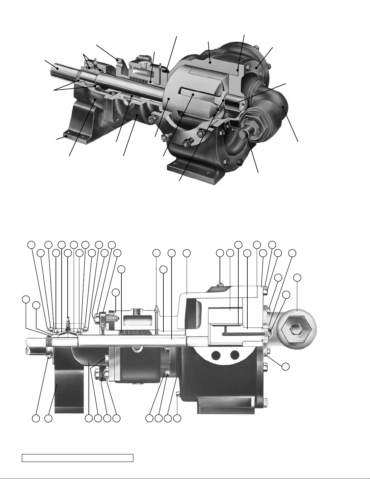
SHAFT
ROLLER
BEARINGS
PACKING
GLAND
ROTOR BEARING
SLEEVE GASKET
ROTOR BEARING
SLEEVE BUSHING
HEAD
GASKET
CASING
HEAD
END
CAPS
BEARING
HOUSING
STAND
THRUST
BEARING
HOUSING
PACKED PUMPS
Model N and R333
6
4 4
5
8 876
7 9 11
PACKING
ROTOR
BEARING
SLEEVE
28
5
29
ROTOR
IDLER
IDLER
BUSHING
FIGURE 3
CUTAWAY FROM PACKED PUMP
MODEL N333
15 36169
18 37
17
IDLER PIN
RELIEF VALVE
RELIEF VALVE ADJUSTING
SCREW CAP
21
2019
22
24
2
3
1 10 3027 35343332 31
13
12
14
36
FIGURE 4
SECTIONAL VIEW MODELS N AND R333
23
25
26
38
SECTION TSM 153 ISSUE D PAGE 4 OF 16
ITEM NAME OF PART ITEM NAME OF PART ITEM NAME OF PART
1 Locknut 14 Bushing, Rotor Bearing Sleeve 27 Bearing Housing Stand
2 Lockwasher 15 Casing 28 Packing Gland Stud
3 Bearing Spacer Collar 16 Rotor and Shaft 29 Packing Gland Nut
4 Capscrew for End Cap Lock 17 Idler and Bushing 30 Bearing Housing Stud
5 End Cap Lock 18 Idler Bushing 31 Bearing Housing Nut
6 Lip Seal 19 Idler Pin 32 Bearing Housing Capscrew
7 End Cap 20 Head and Idler Pin 33 Stud for Rotor Bearing Sleeve
8 Roller Bearing 21 Nut for Head 34 Nut for Rotor Bearing Sleeve
9 Grease Fitting 22 Stud for Head 35 Rotor Bearing Sleeve Gasket
10 Thrust Bearing Housing 23 Capscrew for Valve 36 Pipe Plug
11 Packing Gland 24 Idler Pin Nut (Not N) 37 Head Gasket
12 Rotor Bearing Sleeve & Bushing 25 Internal Relief Valve 38 Relief Valve Gasket
13 Packing 26 Pipe Plug * Suckback Line (Not Illustrated)
DETAILS FOR SECTIONAL VIEW - MODELS N AND R333
DISASSEMBLY
DANGER !
Before opening any Viking pump liquid
chamber (pumping chamber, reservoir,
relief valve adjusting cap fitting, etc.)
Be sure:
1. That any pressure in the chamber has
been completely vented through the
suction or discharge lines or other
appropriate openings or connections.
2. That the driving means (motor,
turbine, engine, etc.) has been “locked
out” or made non-operational so that
it cannot be started while work is
being done on pump.
3. That you know what liquid the
pump has been handling and the
precautions necessary to safely
handle the liquid. Obtain a material
safety data sheet (MSDS) for the
liquid to be sure these precautions
are understood.
1. Mark head and casing before disassembly to ensure
proper reassembly. The idler pin, which is offset in pump
head, must be positioned towards and equal distance
between port connections to allow for proper flow of
liquid through pump.
It is not necessary to remove relief valve to take head
off pump; however, removing relief valve will lessen total
weight of part. Do not use chain or cable around relief
value body to support the head during removal. For
Pressure Relief Instructions, refer to page 14.
Remove nuts from head. Jackscrews should be used to
back head away from casing. Refer to figure 5. Proper
size and length of jackscrews for pump size are shown in
figure 6. The use of a hoist to support head will facilitate
its removal.
Back head away from casing. Remove head from pump.
Do not allow idler to fall from idler pin. To prevent this,
tilt top of head back when removing. A lifting hook will
provide adequate connection for hoisting head. If a hoist
is not available, cribbing or blocking can be used to
support head. This will eliminate having to lift head into
position when reassembling pump.
Failure to follow above listed
precautionary measures may result in
serious injury or death.
JACKSCREWS
FIGURE 5
SECTION TSM 153 ISSUE D PAGE 5 OF 16
 Loading...