

Viking Pump TSM151.2 User Manual

r
r
TECHNICAL SERVICE MANUAL
HEAVY-DUTY STEEL EXTERNAL BRACKET MOUNTED PUMPS
CONTENTS
Introduction
Special Information
Maintenance
Packed Pumps
Mechanical Seal Pumps
Standard Rubber Bellows Type
(Sizes LS, Q, QS & M)
Optional Teflon Seal
Thrust Bearing Adjustment
Installation of Carbon Graphite Bushings
Pressure Relief Valve Instructions
11
12
12
13
1
2
2
3
7
INTRODUCTION
The illustrations in this manual are for identification purposes
only and cannot be used for ordering parts. Obtain a parts
list from the factory or a Viking Representative. Always give
complete name of part, part number and material with model
number and serial number of pump when ordering repai
parts. The unmounted pump or pump unit model numbe
and serial number are on the nameplate.
In the Viking model number system, basic size letters are
combined with series number (123 and 4123) indicating both
unmounted or mounted pump unit.
SERIES 123 AND 4123
SIZES LS, Q, QS, M
SECTION TSM 151.2
PAGE 1 OF 14
ISSUE B
FIGURE 1
SIZE LS
UNMOUNTED PUMP UNITS
PACKED
LS123
Q123
QS123
M123
This manual deals only with Series 123 and 4123 heavyduty Steel External Bracket Mounted Pumps. Refer to
Figures 1 through 14 for general configuration and
nomenclature used in this manual. Pump specifications and
recommendations are listed in Catalog Section 151, Series
123 and 4123 Heavy-Duty Steel External Bracket Mounted
Pumps.
MECH. SEAL
LS4123
Q4123
QS4123
M4123
Units are designated by the unmounted pump model numbers
followed by a letter(s)
indicating drive style.
V = V-Belt
D = Direct Connected
R = Viking Speed Reducer
P = Commercial Speed Reducer
VIKING PUMP INC. •
A Unit of IDEX Corporation •
FIGURE 2
SIZES Q, QS AND M

SPECIAL INFORMATION
DANGER
BEFORE OPENING ANY VIKING PUMP
LIQUID CHAMBER (PUMPING CHAM BER,
RESERVOIR, RELIEF V ALVE ADJUSTING
CAP FITTING, ETC.) BE SURE:
1. THAT ANY PRESSURE IN CHAMBER
HAS BEEN COMPLETELY VENTED
THROUGH SUCTION OR DISCHARGE
LINES OR OTHER APPROPRIATE
OPENINGS OR CONNECTIONS.
2. THAT THE DRIVING M EANS (MOTOR,
TURBINE, ENGINE, ETC.) HAS BEEN
"LOCKED OUT" OR MADE NONOPERATIONAL SO THAT IT CANNOT
BE START ED WHILE W ORK IS BEING
DONE ON PUMP.
3. THAT YOU KNOW WHAT LI QUID THE
PUMP HAS BEEN HANDLING AND
THE PRECAUTIONS NECESSARY TO
SAFELY HANDLE THE LIQUID.
OBTAIN A MATERIAL SAFETY DATA
SHEET (MSDS) FOR THE LIQUID TO
BE SURE THES E PRECAUTIONS ARE
UNDERSTOOD
FAILURE TO FOLLOW THE ABOVE
LISTED PRECAUTIONARY MEASURES
MAY RESULT IN SERIOUS INJURY OR
DEATH.
ROTATION: Viking pumps operate equally well in a clockwise
or counterclockwise rotation. Shaft rotation determines which
port is suction and which is discharge. Port in area where
pumping elements (gear teeth) come out of mesh is suction
port.
PRESSURE RELIEF VALVES:
1. Viking pumps are positive placement pumps and must be
provided with some sort of pressure protection. This may
be a relief valve mounted directly on the pump, an inline
pressure relief valve, a torque limiting device or a rupture
disk.
2. There are relief valve options available on those pump
models designed to accept a relief valve. Options may
include a return to tank relief valve and a jacketed relief
valve. Pumps equipped with a jacketed head plate are
generally not available with a relief valve.
3. If pump rotation is to be reversed during operation,
pressure protection must be provided on both sides of
pump.
4. Relief valve adjusting screw cap must always point
towards suction side of pump. If pump rotation is
reversed, remove pressure relief valve and turn end for
end. Refer to Figures 1 and 2.
5. Pressure relief valves cannot be used to control pump
flow or regulate discharge pressure.
For additional information on pressure relief valves, refer to
Technical Service Manual TSM000 and Engineering Service
Bulletin ESB-31.
SPECIAL MECHANICAL SEALS: Extra care should be taken
in repair of pumps with mechanical seals. Read and follow all
special information supplied with pump.
MAINTENANCE
Series 123 and 4123 pumps are designed for long, troublefree service life under a wide variety of application conditions
with a minimum of maintenance. The points listed below will
help provide long service life.
LUBRICATION: External lubrication must be applied slowly
with a handgun to all lubrication fittings every 500 hours of
operation with multi-purpose grease, NLGI # 2. Do not overgrease. Applications involving very high or low temperatures
will require other types of lubrication. Refer to Engineering
Service Bulleting ESB-515. Consult factory with specific
lubrication questions.
PACKING ADJUSTMENT: New packed pumps require initial
packing adjustment to control leakage as packing “runs in”.
Make initial adjustments carefully and do not over-tighten
packing gland. After initial adjustment, inspection will reveal
need for packing gland adjustment or packing replacement.
Refer to instructions under DISASSEMBLY, page 4, and
Assembly, page 5, regarding repacking pump.
CLEANING PUMP: Keep pump as clean as possible. This
will facilitate inspection; adjustment and repair work and help
prevent overlooking a dirt covered grease fitting.
STORAGE: If pump is to be stored, or not used for six months
or more, pump must be drained and a light coat of nondetergent SAE 30 weight oil must be applied to all internal
pump parts. Lubricate fittings and apply grease to pump shaft
extension. Viking suggests rotating pump shaft by hand one
complete revolution every 30 days to circulate the oil.
SUGGESTED REPAIR TOOLS: The following tools must be
available to properly repair Series 123 and 4123 pumps.
These tools are in addition to standard mechanics’ tools such
as open end wrenches, pliers, screwdrivers etc. Most of the
items can be obtained from an industrial supply house.
1. Soft Headed Hammer
2. Allen Wrenches (some mechanical seals and set
collars)
3. Packing hooks, flex ible (packe d pumps)
Large for 0.375 inch and up cross section packing
4. Mechanical seal insta llation sle ev e
2-751-005-630 for 2.4375 inch Q-M4123
5. Bearing locknut spanner wr ench
(Source: #471 J.H. Williams & Co. or equal)
6. Spanner wrench, adjustable pin type for use on double
end caps (Source #482 J.H. Williams & Co or equal)
7. Brass Bar
8. Arbor Press
SECTION TSM 151.2
ISSUE B PAGE 2 OF 14
PACKED PUMPS
G
IDLER
HEAD
PACKING GLAND
BRACKET
HAFT
PACKIN
R
T
CUTAWAY OF PACKED PUMP MODEL Q OR M123 (QS casing has opposite ports)
FIGURE 3
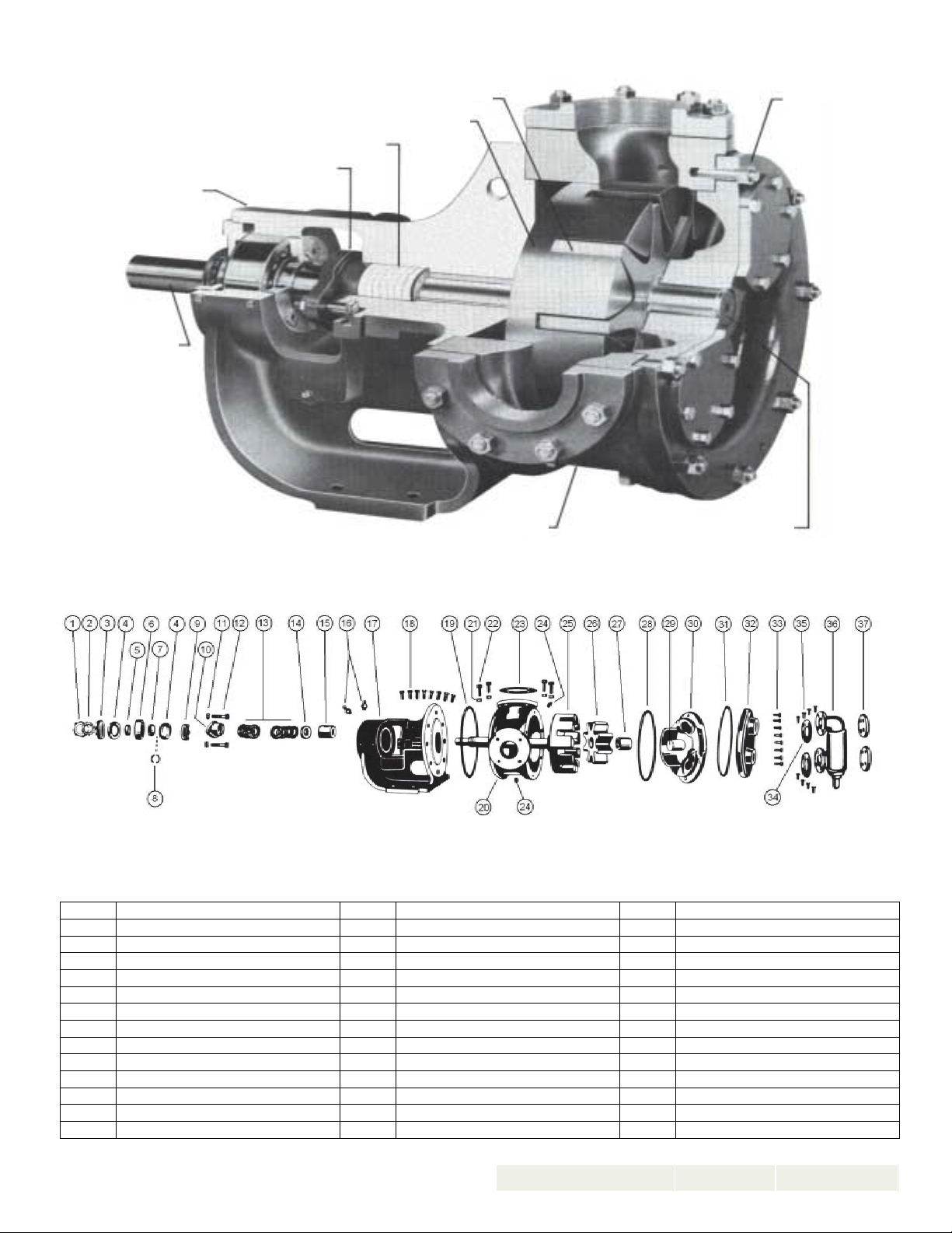
EXPLODED VIEW MODEL LS123
ITEM NAME OF PART ITEM NAME OF PART ITEM NAME OF PART
1
Locknut
2
Lockwasher
3
End Cap, Outer
4
Lip Seal for End Cap
5
Bearing Spacer Collar, Outer
6
Ball Bearing
7
Bearing Spacer Col lar, Inner
8
Ring, Half Round
9
End Cap, Inner
10
Packing Gland
11
Packing Gland Nut
12
Packing Gland Capscrew
13
Packing
14
Packing Retainer Washer
15
Bracket Bushing
16
Grease Fitting
17
Bracket and Bushing
18
Capscrew for Bracket
19
Bracket Gask et
20
Casing
21
Nut for Flanges
22
Capscrew for Flanges
23
Pipe Flange Gasket
24
Pipe Plug
25
Rotor and Shaft
26
Idler and Bushing
27
Idler Bushing
28
Head Gasket
29
Idler Pin
30
Head and Idler Pin
31
Gasket for Jacket Head Plate
32
Jacket Head Plate
33
Capscrew for Head
34
Relief Valve Gasket
35
Capscrew for Relief Valve
36
Internal Relief Valve
37
Cover Plate, Relief Valve
38
39
SECTION TSM 151.2
ISSUE B PAGE 3 OF 14

3
Y
EXPLODED VIEW Q, QS AND M12
ITEM NAME OF PART ITEM NAME OF PART ITEM NAME OF PART
1
Locknut
2
Lockwasher
3
End Cap, Outer
4
Lip Seal for End Cap
5
Bearing Spacer Collar
6
Ball Bearing
7
End Cap, Inner
8
Packing Gland
9
Packing Gland Nut
10
Packing Gland Capscrew
11
Packing
12
* QS Casing has Opposite ports
Packing Retainer Washer
13
Bracket Bushing
14
Bracket and Bushing
15
Grease Fitting
16
Capscrew for Bracket
17
Bracket Gask et
18
Nut, for Flanges
19
Stud for Flanges
20 Casing * 32
21
Pipe Flange Gasket
22
Pipe Plug Suckback Line, Not illus
23
Rotor and Shaft
24
Idler and Bushing
25
Idler Bushing
26
Head Gasket
27
Idler Pin
28
Head and Idler Pin
29
Stud for Head
30
Nut for Head
31
Relief Valve Gasket
Capscrew for Relief Valve
33
Internal Relief Valve
DANGER
BEFORE OPENING ANY VIKING PUMP
LIQUID CHAMBER (PUMPING CHAMBER,
RESERVOIR, RELIEF VALVE ADJUSTING
CAP FITTING, ETC.) BE SURE:
1. THAT ANY PRESSURE IN CHAMBER
HAS BEEN COMPLETELY VENTED
THROUGH SUCTION OR DISCHARGE
LINES OR OTHER APPROPRIATE
OPENINGS OR CONNECTIONS.
2. THAT THE DRIVING MEANS (MOTOR,
TURBINE, ENGINE, ETC.) HAS BEEN
"LOCKED OUT" OR MADE NONOPERATIONAL SO THAT IT CANNOT
BE STARTED WHILE WORK IS BEING
DONE ON PUMP.
3. THAT YOU KNOW WHAT LIQUID THE
PUMP HAS BEEN HANDLING AND THE
PRECAUTIONS NECESSARY TO
SAFELY HANDLE THE LI QUID. OBTAIN
A MATERIAL SAFETY DATA SHEET
(MSDS) FOR THE LIQUID T O BE SURE
THESE PRECAUTIONS ARE
UNDERSTOOD
FAILURE TO FOLLOW THE ABOVE LISTED
PRECAUTIONARY MEASURES MAY
RESULT IN SERIOUS INJURY OR DEATH.
DISASSEMBL
1. Mark head and casing before disassembly to insure
proper reassembly. The idler pin, which is offset in
pump head, must be positioned toward and equal
distance between port connections to allow for proper
flow of liquid through pump.
Remove head from pump. Do not allow idler to fall
from idler pin. Tilt top of head back when removing to
prevent this. Avoid damaging head gasket. If pump is
furnished with pressure relief valve, it need not be
removed from head or disassembled at this point.
Refer to PRESSURE RELIEF VALVE
INSTRUCTIONS, page 13.
If LS pump has jacketed head plate, it will separate from
head when it is removed. The gasket between head
and jacket head plate must be totally removed. Use
new gasket when assembling pump. Q, QS and M
pumps have jacketed plate welded to head.
2. Remove idler and bushing assembly.
3. Insert length of hardwood or brass through port opening
between rotor teeth to keep shaft from turning. Bend up
tang of lockwasher and with a spanner wrench remove
locknut and lockwasher from shaft.
Remove length of hardwood or brass from port opening
4. Remove packing gland nuts.
5. Tap shaft forward approximately 0.50 inch and remove
pair of half round rings under inner bearing spacer
collar. Q, QS and M size do not use half round rings.
SECTION TSM 151.2
ISSUE B PAGE 4 OF 14
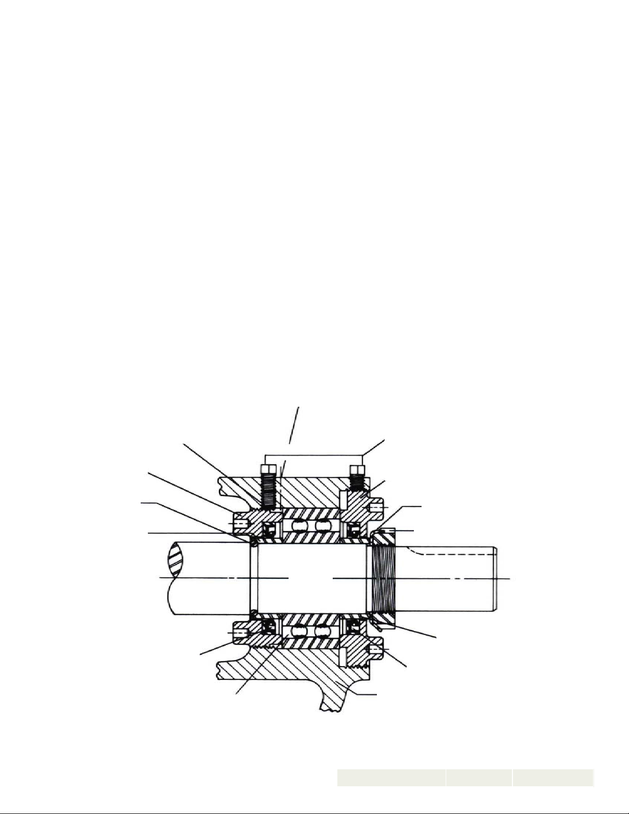
6. Carefully remove rotor and shaft to avoid damaging
G
SHAFT
INNER END CAP
R
7. Remove packing gland from side of bracket.
bracket bushing.
8. Loosen four setscrews over the inner and outer end
caps. Remove both end caps with lipseals, spacer
collars and ball bearing. Refer to Figure 4.
The inner cap can be removed through the side opening
of the bracket.
9. Remove packing and packing retainer washer.
10. Clean all parts thoroughly and examine for wear and
damage. Check lip seals, ball bearing, bushings and
idler pin and replace if necessary. Check all other parts
for nicks, burrs, excessive wear and replace if
necessary.
Wash bearings in clean solvent. Blow out bearings with
compressed air. Do not allow bearings to spin; turn
them slowly by hand. Spinning bearings will damage
race and balls. Make sure bearings are clean, then
lubricate with non-detergent SAE 30-weight oil and
check for roughness. Roughness can be determined
by turning outer race by hand.
If bearings have roughness, bearings will need to be
replaced.
11. Casing can be checked for wear or damage while
mounted on bracket.
ASSEMBLY
1. Install bracket bushing. If bracket bushing has a
lubrication groove, install bushing with groove at 6:00
o’clock position in bracket. If carbon graphite, refer to
INSTALLATION OF CARBON GRAPHITE BUSHINGS,
page 12.
2. Coat shaft of rotor shaft asse m bly w it h no n- de tergent SAE
30 weight oil. Start end of shaft in bracket bushing turning
from right to left, slow ly pu shing rotor in c asing.
3. Place packing retainer washer in bottom of packing
chamber and pack pum p with new packi ng. Us e packing
suitable for liquid being pumped. Install packing,
staggering the joints from one side of shaft to other.
Lubricate packing rings with oil, grease or graphite to aid
assembly. A lengt h of pipe will h elp to se at each packi ng
ring.
4. Insta ll packin g gland, capscre ws and nut s Back rotor an d
shaft out o f casing j ust fa r enough to inse rt packi ng glan d
through side opening of bracket over end of shaft. Make
sure gland is installed square and nuts are tightened
evenly. Tighten nuts wren ch tight then back off until gland
is slightly l oose.
5. Coat idler pin with non-detergent SAE 30 weight oil and
place idler and bushing on idler pin in head. If replacing
carbon graphite bushing, refer to INSTALLATION OF
CARBON GRAPHITE BUSHINGS, page 12.
HALF ROUND
INNER SPACER
COLLAR
INNER LIP
SEAL
REA
E FITTIN
L
ATI
N
TER END
AP
LOCKWASHE
L
KN
T
OUTER SPACER
TER LIP
COLLAR
EAL
BALL BEARIN
FI
RE 4
SECTION TSM 151.2
ISSUE B PAGE 5 OF 14
 Loading...