

Viking Pump TSM1470 User Manual
Electronic copies of the most current TSM issue can be found on the Viking Pump website at www.vikingpump.com
TECHNICAL SERVICE MANUAL
INSTALLATION, START UP, TROUBLESHOOTING,
PREVENTIVE MAINTENANCE, DO’S & DON’TS
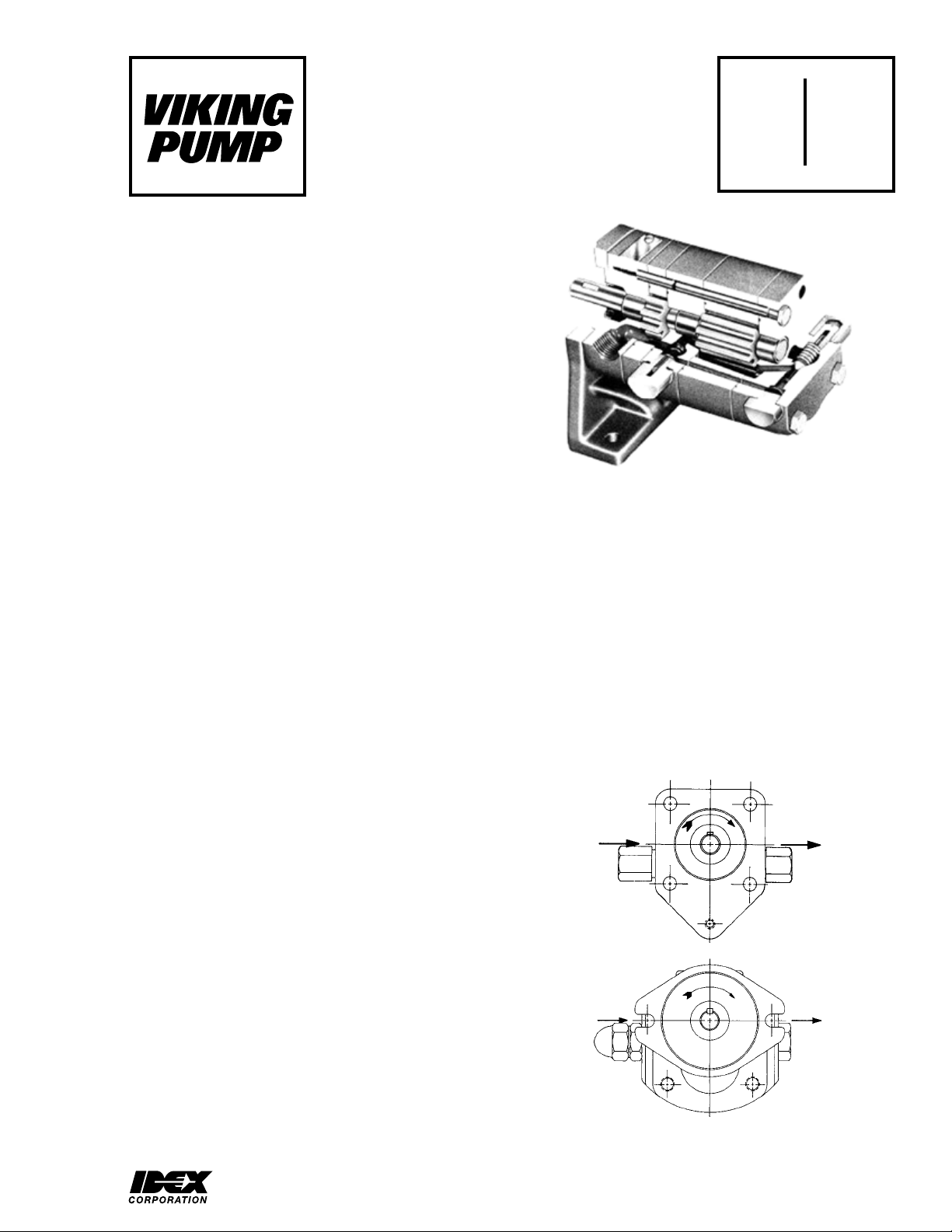
GP-04, GP-05 & GP-07 HI-LO DOUBLE PUMPS
CONTENTS
Introduction . . . . . . . . . . . . . . . . . . . . . . . 1
Repair . . . . . . . . . . . . . . . . . . . . . . . . . . 1
Safety Information. . . . . . . . . . . . . . . . . . . . 2
Installation. . . . . . . . . . . . . . . . . . . . . . . . 3
Start Up . . . . . . . . . . . . . . . . . . . . . . . . . 4
Troubleshooting. . . . . . . . . . . . . . . . . . . . . 4
Miscellaneous. . . . . . . . . . . . . . . . . . . . . . 5
Do’s and Don’ts . . . . . . . . . . . . . . . . . . . . . 6
INTRODUCTION
General
The following items must be considered prior to pump
installation:
1. Location - locate the pump as close as possible to the
supply of the liquid being pumped. If possible, locate
the pump below the liquid supply. Viking pumps are self
priming; but, the better the suction conditions, the better
the pump will perform.
2. Accessibility - the pump must be accessible for
inspection, maintenance and repair.
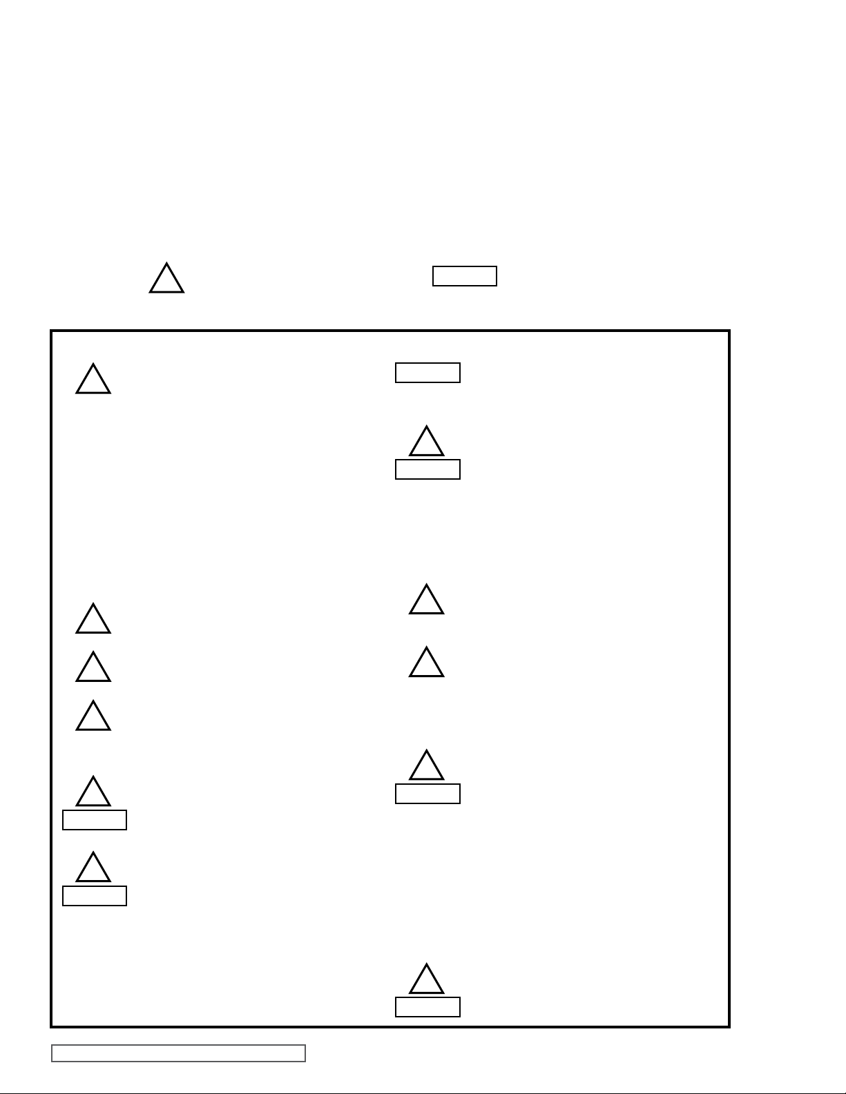
3. Suction/Discharge - Hi-Low Double pumps are
designed for clockwise rotation only (viewed from shaft
end). Refer to Figure 1.
4. Pump Life - pump life is a factor of many parameters,
mainly pressure, speed and duty cycle. Temperature,
contamination and type of hydraulic oil also have a
definite effect.
5. Hydraulic Oil - Viking recommends using industrial
grade hydraulic oil. Temperature must not exceed 150
ºF for optimum life of hydraulic oil. Operating viscosity
must be between 100 and 300 SSU.
6. Filter / Strainer - on a hydraulic system, use a return
line filter with a maximum 10 micron rating to keep the
system clean and free of contaminating elements. A 100
mesh strainer is recommended in the suction line.
7. Pressure Relief Valve - a pressure relief device must
be installed in the system to provide over-pressure
protection. If a line is blocked or closed, pressure builds
up until the motor stalls, drive equipment fails, a pump
part breaks or piping bursts.
8. Discharge Line - select discharge piping, hoses and
fittings rated for maximum system pressure.
9. Storage - if the pump is to be stored, drain the pump and
apply a light coat of non-detergent SAE 30 weight oil to
all internal pump parts. Apply grease to the pump shaft
extension. Viking suggests rotating the pump shaft by
hand one complete revolution every 30 days to circulate
the oil.
SECTION TSM 1470
PAGE 1 Of 8
ISSUE f
FIGURE 2
GP-05 HI-LO
DOUBLE PUMP
REPAIR
1. Parts For A Preventative Maintenance Program -
- Mechanical Seal or Lipseal(s) (Not applicable for Mag
Drive pumps)
- O-rings
2. Parts For A Major Overhaul - The Viking Spur Gear
series pumps have very tight clearances and precision
machining tolerances, and wear on any of the parts will
typically indicate that most of the critical parts are worn.
Therefore, if wear is found on any of the pump parts,
Viking recommends replacing the entire pump. Always
supply the serial number from your pump nameplate
when requesting a replacement.
S
S
FIGURE 1
D
D
VIKING PUMP, INC. • A Unit of IDEX Corporation • Cedar Falls, IA 50613 USAVIKING PUMP, INC. • A Unit of IDEX Corporation • Cedar Falls, IA 50613 USA
SAFETY INFORMATION AND INSTRUCTIONS
IMPROPER INSTALLATION, OPERATION OR MAINTENANCE OF PUMP MAY CAUSE SERIOUS INJURY
OR DEATH AND/OR RESULT IN DAMAGE TO PUMP AND/OR OTHER EQUIPMENT. VIKING’S WARRANTY
DOES NOT COVER FAILURE DUE TO IMPROPER INSTALLATION, OPERATION OR MAINTENANCE.
THIS INFORMATION MUST BE FULLY READ BEFORE BEGINNING INSTALLATION, OPERATION OR
MAINTENANCE OF PUMP AND MUST BE KEPT WITH PUMP. PUMP MUST BE INSTALLED, OPERATED
AND MAINTAINED ONLY BY SUITABLY TRAINED AND QUALIFIED PERSONS.
THE FOLLOWING SAFETY INSTRUCTIONS MUST BE FOLLOWED AND ADHERED TO AT ALL TIMES.
Symbol
Legend :
!
!
!
!
!
WARNING
!
WARNING
Danger - Failure to follow the indicated
instruction may result in serious injury
!
or death.
BEFORE opening any liquid chamber (pumping
chamber, reservoir, relief valve adjusting cap fitting,
etc.) be sure that :
● Any pressure in the chamber has been completely
vented through the suction or discharge lines or
other appropriate openings or connections.
● The pump drive system means (motor, turbine,
engine, etc.) has been “locked out” or otherwise
been made non-operational so that it cannot be
started while work is being done on the pump.
● You know what material the pump has been
handling, have obtained a material safety data
sheet (MSDS) for the material, and understand
and follow all precautions appropriate for the safe
handling of the material.
BEFORE operating the pump, be sure all drive guards
are in place.
DO NOT operate pump if the suction or discharge
piping is not connected.
DO NOT place fingers into the pumping chamber or
its connection ports or into any part of the drive train
if there is any possibility of the pump shafts being
rotated.
DO NOT exceed the pumps rated pressure, speed, and
temperature, or change the system/duty parameters
from those the pump was originally supplied, without
confirming its suitability for the new service.
BEFORE operating the pump, be sure that:
● It is clean and free from debris
● all valves in the suction and discharge pipelines
are fully opened.
● All piping connected to the pump is fully supported
and correctly aligned with the pump.
● Pump rotation is correct for the desired direction
of flow.
WARNING
WARNING
!
WARNING
!
!
!
WARNING
!
WARNING
Warning - In addition to possible serious
injury or death, failure to follow the
indicated instruction may cause damage
to pump and/or other equipment.
INSTALL pressure gauges/sensors next to the
pump suction and discharge connections to monitor
pressures.
USE extreme caution when lifting the pump. Suitable
lifting devices should be used when appropriate. Lifting
eyes installed on the pump must be used only to lift
the pump, not the pump with drive and/or base plate.
If the pump is mounted on a base plate, the base plate
must be used for all lifting purposes. If slings are used
for lifting, they must be safely and securely attached.
For weight of the pump alone (which does not include
the drive and/or base plate) refer to the Viking Pump
product catalog.
DO NOT attempt to dismantle a pressure relief valve
that has not had the spring pressure relieved or is
mounted on a pump that is operating.
AVOID contact with hot areas of the pump and/or
drive. Certain operating conditions, temperature
control devices (jackets, heat-tracing, etc.), improper
installation, improper operation, and improper
maintenance can all cause high temperatures on the
pump and/or drive.
THE PUMP must be provided with pressure protection.
This may be provided through a relief valve mounted
directly on the pump, an in-line pressure relief valve,
a torque limiting device, or a rupture disk. If pump
rotation may be reversed during operation, pressure
protection must be provided on both sides of pump.
Relief valve adjusting screw caps must always point
towards suction side of the pump. If pump rotation is
reversed, position of the relief valve must be changed.
Pressure relief valves cannot be used to control pump
flow or regulate discharge pressure. For additional
information, refer to Viking Pump’s Technical Service
Manual TSM 000 and Engineering Service Bulletin
ESB-31.
THE PUMP must be installed in a matter that allows
safe access for routine maintenance and for inspection
during operation to check for leakage and monitor
pump operation.
SECTION TSM 1470 ISSUE F PAGE 2 OF 8
INSTALLATION
Mounting
1. Surfaces to which the pump mounts against must be
clean and flat.
2. Use SAE Grade 5 or better capscrews to mount the
pump.
3. The 4 mounting capscrews for GP-04 and GP-05 pumps
must have a minimum of ½ inch engagement and must
be torqued evenly to 12-15 ft.-lbs.
4. The 2 mounting capscrews for the SG-07 pumps must
have a minimum of ½ inch thread engagement and must
be torqued evenly to 50-55 ft.-lbs.
5. Do not strike or press the pump drive coupling half to
install on the pump shaft. Damage to the pump or
coupling may result. If the coupling does not slide onto
the pump shaft, inspect the coupling bore, shaft and key
for nicks or burrs and remove if present.
6. Once the pump has been mounted, place a small amount
of compatible liquid into the suction port and turn by hand
to ensure the pump turns freely.
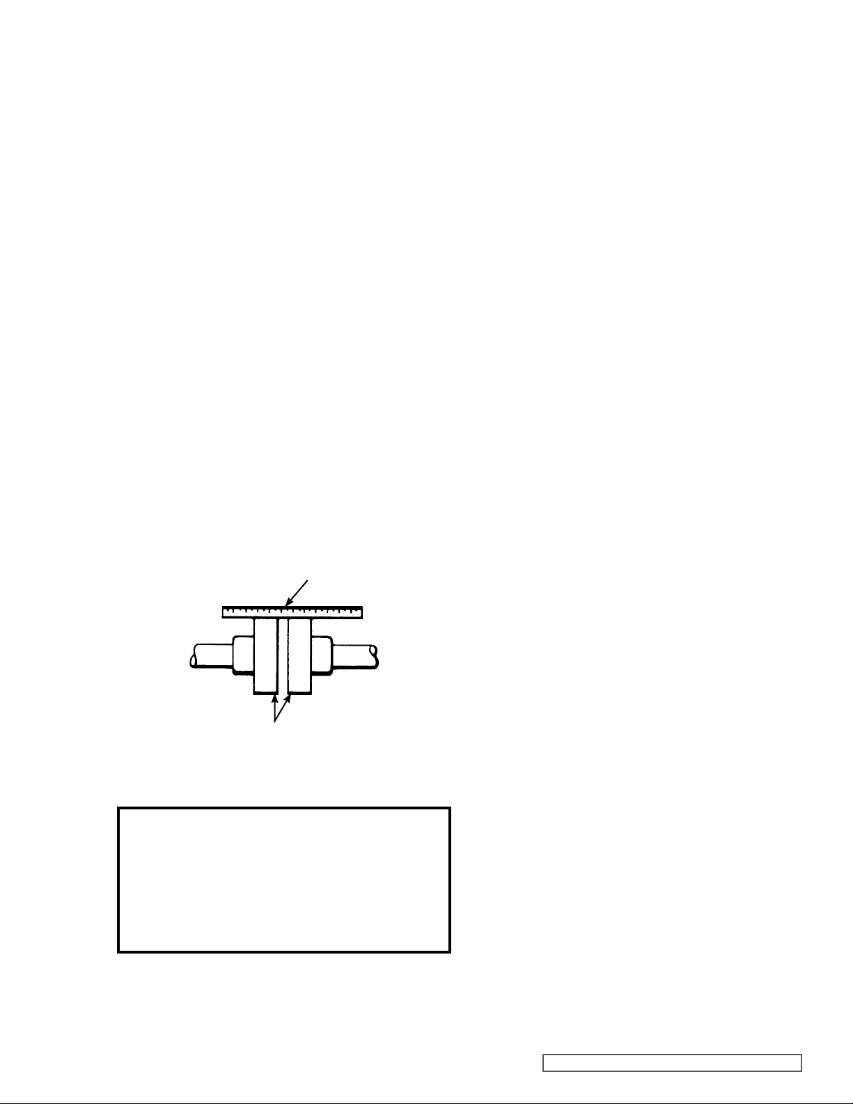
Alignment
Check alignment after mounting.
If the unit has a flexible coupling, remove any coupling guards
or covers and check alignment of coupling halves. A straight
edge (a piece of key stock will work) across the coupling
must rest evenly on both rims at the top, bottom and sides.
See Figure 3.
USE STRAIGHT EDGE.
THESE SURFACES
MUST BE PARALLEL.
CHECK WIDTH BETWEEN THESE SURFACES WITH INSIDE CALLIPERS OR FEELER
GAUGE TO BE CERTAIN THE FACES ARE EQUAL DISTANCE APART AND PARALLEL.
FIGURE 3
Danger !
Before starting pump, be sure all drive equipment
guards are in place.
Failure to properly mount guards may result in serious injury or death.
Piping/Hose
The cause of many pumping problems can be traced to the
suction piping. It should always be as large in diameter and
as short in length as possible.
Before starting the layout and installation of your piping
system, consider the following points:
1. Never use piping smaller than the pump port
connections. Piping larger in diameter than the port
connection is sometimes required to reduce friction
losses.
2. Be sure the inside of the pipe is clean before installing.
3. Do not use galvanized piping.
4. When approaching an obstacle in the suction line,
go around instead of over it. Going over an obstacle
may create an air pocket. Where practical, slope the
piping so no air or liquid pockets will be formed. Air
pockets in the suction line make it hard for the pump
to prime.
5. Viking recommends using a strainer on the suction
side of the pump. The strainer will keep foreign
objects from going into the pump. A 100 mesh
strainer is recommended. Provisions must be
made for cleaning the strainer. Use of a strainer is
particularly important at start up to help clean the
system of weld beads, pipe scale and other foreign
objects.
6. On a hydraulic system, it is recommended that a
return line filter be installed having a maximum 10
micron rating.
7. A pressure relief valve is required in the discharge
line. See Pressure Relief Valves, General page 1
item 7.
8. The pump must not be used to support piping.
Weight of the pipe must be carried by hangers,
supports, stands, etc.
9. When fastening to the pump do not impose any
strain on the pump casing. “Springing” or “drawing”
piping up to the pump will cause distortion, possible
misalignment and probable rapid wear of the pump.
Do not use the pump to correct errors in the piping
layout or assembly.
10. All joints of piping system must be tight; liquid thread
sealant will help assure leak free threaded joints.
Loose joints result in liquid leaks or suction side
leaks. Air leaks make the pump noisy and reduce
flow. CAUTION: Be careful not to over tighten
fittings as this can cause cracked joints. Do not use
PTFE / plumber’s tape. Reduced friction makes
over tightening very easy and will result in cracked
ports.
11. Drive alignment must be checked after the piping is
hooked up.
SECTION TSM 1470 ISSUE F PAGE 3 OF 8
 Loading...