

Viking K-1900-8-IP PRODUCT MANUAL
Designed, Manufactured and Supported in the USA
VIKING
PRODUCT MANUAL
SECURITY & COMMUNICATION SOLUTIONS
Vandal Resistant VoIP Phone with
Auto Dialer, Keypad, and Entry System
The K-1900-8-IP Series panel phone can either auto-dial a phone number each time the handset is lifted, be used
as a multi-number auto-dialer, or be used as a standard manual dial phone. The K-1900-8-IP Series phones are
designed to provide quick and reliable communication for SIP VoIP phone systems with PoE. The unit can be
programmed from any PC on the same LAN or remotely using a Static IP Address. The K-1900-8-IP Series phone
can dial up to 250 programmable numbers and another 250 rollover numbers.
When a call initiated by the K-1900-8-IP Series phone is answered by an apartment or business tenant, a built-in
contact closure may be activated to control an electric gate or door strike. Up to 1,000 keyless entry codes may
be programmed, providing tenants with keyless entry. A 26 Bit Wiegand input is provided for adding an optional
proximity card reader with capacity to program up to 1,000 card numbers. Keyless entry codes and card numbers
can be programmed to only allow access at specific times and/or day of the week. A request for exit (REX) input
is included for easy exiting. The K-1900-8-IP Series phone also has automatic event logging allowing you to review
the time and date of the call, which door was open/closed, what keyless entry code or proximity card was used,
request for exit usage and whether it was an inbound or outbound call.
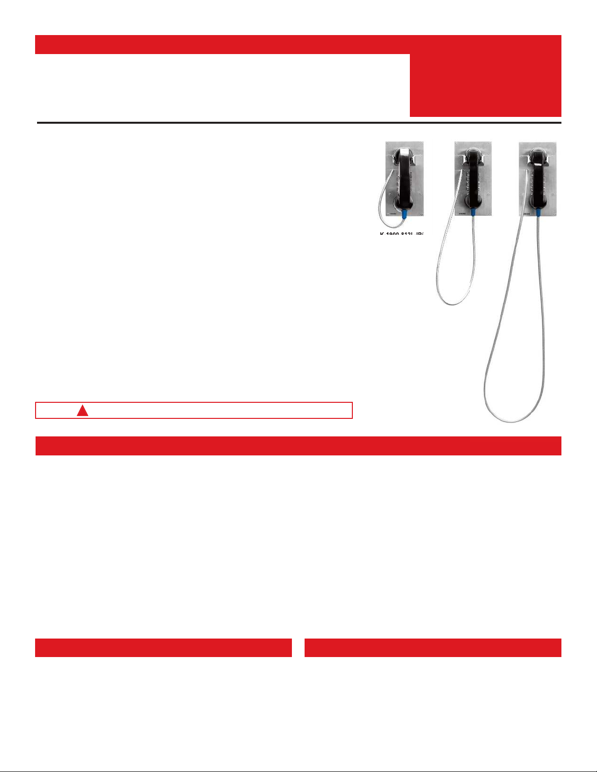
The K-1900-812L-IP and K-1900812LIPEWP have a 12” long armored cable with internal stainless steel lanyard
for additional cable strength.
The K-1900-8-IP-EWP and K-1900812LIPEWP shares all of the features of the K-1900-8-IP and K-1900-812L-IP
in addition to Enhanced Weather Protection (EWP) for outdoor installations where the unit is exposed to precipitation
or condensation. EWP products are designed to meet IP66 standards and may feature foam rubber gaskets,
sealed connections, gel-filled butt connectors, as well as potted circuit boards with internally sealed, field-adjustable
trim pots and DIP switches for easy on-site programming. For more information on EWP, see DOD 859.
Installation requires a Network Administrator / IT Technician
!
K-1900-812L-IP/
K-1900812LIPEWP
with 12” armored
cable and lanyard
K-1900-8-IP Series
VoIP Phone with Auto Dialer,
Keypad, and Entry System
January 10, 2020
K-1900-8-IP
with 36”
armored cable
K-1900-8-IP-EWP
with 54” armored
cable
Features
• Vandal Resistant Features: 12 gauge 316 stainless steel faceplate with permanent
laser etched graphics. Heavy duty metal keypad, hook switch, armored cable and T-10
security Torx drive mounting screws.
• Weather Resistant Features: Marine grade 316 stainless steel faceplate and Torx
security screws. Internally sealed keypad. Faceplate gaskets (on EWP models).
• Ring with adjustable volume and cadence
• Hearing aid compatible amplified handset with sealed push button volume control
• Two sets of SPDT 2 Amp relay contacts for door/gate or camera control
• Optional RC-4A for Secure Remote Relay Control, see DOD 582
• SIP compliant (see page 2 for list of compatible IP-PBX phone systems)
• PoE powered (class 2, <6.5 Watts)
• Outbound Proxy, Authentication ID, Peer to Peer, VLAN Tagging
• Network downloadable firmware
• K-1900-812L-IP and K-1900812LIPEWP: 12” armored handset cable
• K-1900-8-IP: 36” armored handset cable
• K-1900-8-IP-EWP: 54” armored handset cable
Applications
• Apartment Entry Phone
• Commercial Gate Entrance
• Courtesy Assistance Phone
• Customer Service Phone
• Use with Viking PRX-1 (DOD 221) or PRX-3 (DOD 228) Proximity Card
Readers
• Use with Viking LRT-4 Long Range Transmitter (DOD 226)
• Hot-Line Phone
• Door Entry Phone
• Kiosk Phone with up to
250 number speed dialing
• Programmable to speed dial up to 250 numbers
• 26 Bit Wiegand input for optional proximity card readers, see DOD 221 and 228
• 26 Bit Wiegand output connect to card reader input of an Access Control System
• Cycles to rollover phone number on busy or no-answer
• Program up to 1,000 keyless entry codes and/or proximity card numbers
• Keyless entry codes and proximity card numbers can be programmed to only allow
access at specific times and day of week
• Event logging with time and date stamp
• Optional Enhanced Weather Protection (EWP), EWP products are designed to meet IP66
Ingress Protection Rating, see DOD 859
• Remotely programmable
• Extended temperature range (-40°F to 140°F)
• Flush mount with included steel rough-in box, or use an optional VE-5x10 surface mount
box (not included, see DOD 424)
• Optional VE-LIGHT kit to illuminate the front panel at night, see DOD 428
• Diagnostics (for testing relays)
Specifications
For complete Specifications, see page 2.
www.VikingElectronics.com
Information: 715-386-8861
Specifications
Power: PoE class 2 (<6.5 Watts)
Dimensions for K-1900-8-IP and K-1900-812L-IP Models
Phone only: 5.0” x 10.0” x 4.68” (127mm x 254mm x 119mm)
Including rough-in box: 5.0” x 10.0” x 5.53” (127mm x 254mm x 141mm)
Dimensions for K-1900-8-IP-EWP and K-1900812LIPEWP Models
Phone only: 5.0” x 10.0” x 4.75” (127mm x 254mm x 121mm)
Including rough-in box: 5.0” x 10.0” x 5.61” (127mm x 254mm x 143mm)
Shipping Weight for K-1900-8-IP and K-1900-8-IP-EWP: 5.3 lbs (2.4 kg)
Shipping Weight for K-1900-812L-IP and K-190012L8IPEWP: 5.3 lbs (2.4 kg)
Operating Temperature: -40°F to 140°F (-40° C to 60° C)
Humidity - Standard Models: 5% to 95% non-condensing
Humidity - EWP Models: Up to 100%
Handset Cable Length on K-1900-812L-IP and K-1900812LIPEWP Models: 12” to 12.7” (31 cm to 33 cm)
Handset Cable Length on K-1900-8-IP Model: 34” to 37” (86 cm to 94 cm)
Handset Cable Length on K-1900-8-IP-EWP Model: 52” to 57” (132 cm to 145 cm)
Audio Codecs: G711u, G711a, G722
Network Compliance: IEEE 802.3 af PoE, SIP 2.0 RFC3261, 100BASE-TX with auto cross over
Regulatory Compliance: CE, FCC Part 15 and Canada ICES-003 Class A
Connections: (1) RJ45 10/100 Base-T, (14) gel-filled butt connectors
VoIP SIP System Compatibility
For compatibility and vendor specific detailed configuration instructions, see the Viking VoIP
SIP System Compatibility List, DOD 944. To open and download this PDF file:
Scan the QR code below to open
and download the Viking VoIP
- OR -
SIP System Compatibility List
Important: Exclusion from this list means only that compatibility has not been verified, it does not mean
incompatibility. If you have questions, please call Viking Electronics at 715-386-8861.
1. Go to www.vikingelectronics.com
and enter 944 in the search box
2. Click Application Note (DOD 944)
to open and download the PDF
2

Definitions
Client: A computer or device that makes use of a server. As an example, the client might request a particular file from the server.
DHCP: Dynamic Host Configuration Protocol. In this procedure the network server or router takes note of a client’s MAC address and
assigns an IP address to allow the client to communicate with other devices on the network.
DNS Server: A DNS (Domain Name System) server translates domain names (ie: www.vikingelectronics.com) into an IP address.
Ethernet: Ethernet is the most commonly used LAN
achieve transmission speeds up to 1Gbps.
Host: A computer or device connected to a network.
Host Name: A host name is a label assigned to a device connected to a computer network that is used to identify the device in various
forms of network communication.
Hosts File: A file stored in a computer that lists host names and their corresponding IP addresses with the purpose of mapping addresses
to hosts or vice versa.
Internet: A worldwide system of computer networks running on IP
IP: Internet Protocol is the set of communications conventions that govern the way computers communicate on networks and on the
Internet
IP Address: This is the address that uniquely identifies a host on a network.
LAN: Local Area Network. A LAN is a network connecting computers and other devices within an office or building.
Lease: The amount of time a DHCP
time, the lease can expire and the address can be assigned to another host.
MAC Address: MAC stands for Media Access Control. A MAC address, also called a hardware address or physical address, is a unique
address assigned to a device at the factory. It resides in the device’s memory and is used by routers to send network traffic to the correct
IP address. You can find the MAC address of your K-1900-8-IP phone printed on a white label on the top surface of the PoE LAN port.
Router: A device that forwards data from one network to another. In order to send information to the right location, routers look at IP
Address, MAC Address and Subnet Mask.
RTP: Real-Time Transport Protocol is an Internet protocol standard that specifies a way for programs to manage the real-time transmission
of multimedia data over either unicast or multicast network services.
Server: A computer or device that fulfills requests from a client. This could involve the server sending a particular file requested by the
client.
Session Initiation Protocol (SIP): Is a signaling communications protocol, widely used for controlling multimedia communication sessions
such as voice and video calls over Internet Protocol (IP
which govern establishment, termination and other essential elements of a call.
Static IP Address: A static IP Address has been assigned manually and is permanent until it is manually removed. It is not subject to the
Lease
Subnet: A portion of a network that shares a common address component. On TCP/IP networks, subnets are defined as all devices
whose IP addresses have the same prefix. For example, all devices with IP addresses
same subnet. Dividing a network into subnets is useful for both security and performance reasons. IP networks are divided using a subnet
mask.
TCP/IP: Transmission Control Protocol/Internet Protocol is the suite of communications protocols used to connect hosts on the Internet.
TCP/IP uses several protocols, the two main ones being TCP and IP. TCP/IP is built into the UNIX operating system and is used by the
Internet, making it the de facto standard for transmitting data over networks.
TISP: Telephone Internet Service Provider
WAN: Wide Area Network. A WAN is a network comprising a large geographical area like a state or country. The largest WAN is the
Internet
Wireless Access Point (AP): A device that allows wireless devices to connect to a wired network using Wi-Fi, or related standards. The
AP usually connects to a router (via a wired network) as a standalone device, but it can also be an integral component of the router itself.
Wireless Repeater (Wireless Range Extender): takes an existing signal from a wireless router or access point and rebroadcasts it to
create a second network. When two or more hosts have to be connected with one another over the IEEE 802.11 protocol and the distance
is too long for a direct connection to be established, a wireless repeater is used to bridge the gap.
.
server reserves an address it has assigned. If the address isn’t used by the host for a period of
limitations of a Dynamic IP Address assigned by the DHCP Server. The default static IP Address is: 192.168.154.1
.
technology. An Ethernet Local Area Network typically uses twisted pair wires to
protocol which can be accessed by individual computers or networks.
) networks. The protocol defines the messages that are sent between endpoints,
that start with 100.100.100. would be part of the
3
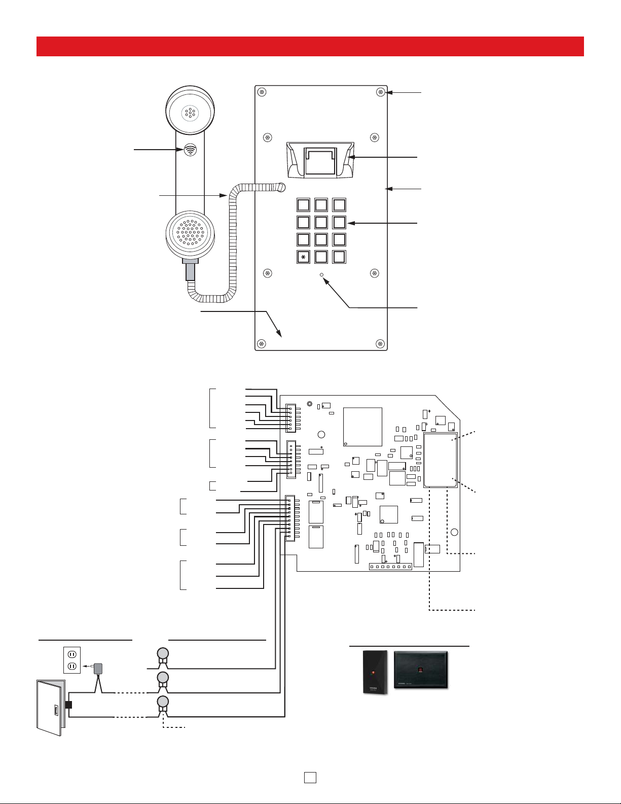
Features Overview
Front View of the
K-1900-8-IP Series Phone
Mounting Screws:
Marine grade 316 stainless steel,
flat head, T-10 Torx security
screws and drive bit (included).
(8) 6-32 X 3/4”
Hearing Aid
Compatible amplified
handset with sealed
push button
volume control
316 Stainless Steel
Armored Cable:
36” on K-1900-8-IP,
54” on K-1900-8-IP-EWP
Laser Etched Graphics:
For long lasting easy to read graphics.
To Handset
26 Bit Wiegand Input / Output
For connecting optional Proximity Card Readers,
see Viking models below right (not included)
or program as a output to connect to the card
reader input of an Access Control System
To Hookswitch
VE-LIGHT, etc.
12 VDC Power Output for
Relay 2 Output Contacts
(2A@30VDC/ 250VAC max)
(12VDC @ 50mA max)
Request for Exit
(REX) Input
- Black
+ Red
Green
Green
COM.
N.C.
N.O.
Black
Black
Yellow
Yellow
Red
Red
White
Green
+ Red
- Black
Black
Red
Brown
Violet
White
2
ABC
JKL
TUV
OPER
3
DEF
6
5
MNO
8
9
WXY
0
#
VIKING
GHI
PRS
1
4
7
Rear (PCB) View of the
K-1900-8-IP Series Phone
Metal Heavy duty Vandal
Resistant Hookswitch
Faceplate Material: 12 gauge 316
stainless steel with a #4 brushed
finish.
Sealed Metal Keypad
Condensation Drain Hole
PoE LAN Port 10/100,
PoE Class 2 (<6.5 Watts):
Connect to your LAN via
MAC:
asdesaxtff
18E80FXXXXXX
RJ45 plug and CAT5 or
greater twisted pair wire.
MAC Address Label: The
MAC address is a unique
12 digit number used by
routers to send network
traffic to the correct IP
address.
Yellow Network Status
LED: Lights steady to
indicate power and data
link. Blinks to indicate
network activity.
Connect to Optional
Doorstrike, Mag Lock,
Gate Controller, etc.
120V AC
connected)
(not
Relay 1
Output Contacts
(2A@30VDC/ 250VAC max)
N.C. (Gray)
Optional Viking Proximity Card Readers
Model PRX-1
Proximity Card
Reader DOD# 221
Green Unit Status LED
Model PRX-3 Medium
Range Proximity Card
Reader DOD# 228
COM. (Blue)
Doorstrike /
Magnetic Lock
(Power typically not
required for gate controllers)
N.O. (Yellow)
* 3 Gel-Filled Butt
Connectors (included)
Note: The gel-filled (water-tight) butt connectors are designed for insulation displacement on 19-26 gauge wire with a maximum insulation of 0.082 inches.
4
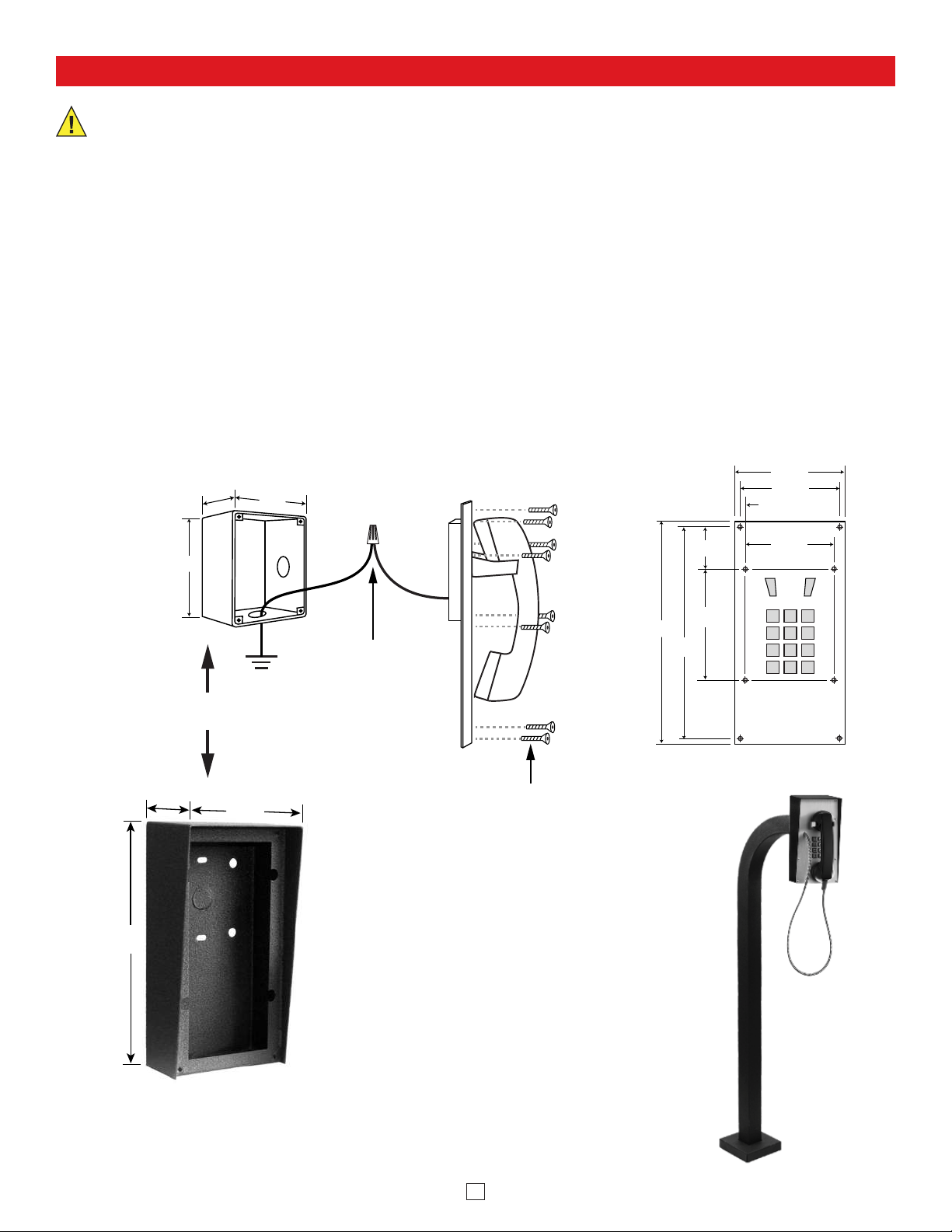
Installation and Mounting
IMPORTANT: Electronic devices are susceptible to lightning and power station electrical surges from both the AC
outlet and the telephone line. It is recommended that a surge protector be installed to protect against such surges.
To install the K-1900-8-IP Series panel phone, attach the phone panel using the provided screws or surface mount using
any of Viking’s VE-5x10 Series surface mount boxes (DOD 424). Note: Four extra screws and nuts are provided to fill the
unused mounting holes.
Viking’s optional Surface Mount Boxes (model VE-5x10 shown below) are designed to be surface mounted to a wall, post,
single gang box or a Viking gooseneck pedestal (model VE-GNP shown below). The K-1900-8-IP Series phone can also
be mounted in an optional VE-9x20 Weatherproof Enclosure, not shown (DOD 413).
Note: When mounting a K-1900-8-IP-EWP in an optional VE-9x20 Weatherproof Enclosure (not shown), the length of the
handset cable must be reduced. Use a 3/32” hex key or bit to loosen the set screw in the brass handset cable retainer. Pull
approximately 18 inches of the cable through the panel and retighten the set screw.
Important: Write down the MAC Address (on the RJ-45 jack) as this may be needed to identify the unit after installation.
Zinc-Plated Steel
Rough-In Box
(included)
2.5"
5.5"
OR
3.69"
5.22"
4.5"
Earth
Ground
Earth Ground the
Green/Yellow
wire using the
provided wire nut
Side View of the
K-1900-8-IP
(8) #6-32 x 3/4" Stainless
Steel T-10 Torx Security
Screws (included)
10.0"
9.5"
Front View of the
K-1900-8-IP
5.00"
4.50"
0.23"
1.72"
5.12"
4.04"
10.14"
Optional Surface Mount Box,
model VE-5x10 shown
(not included) other models
also available
Viking’s optional Surface Mount Boxes
(VE-5x10 shown left) are designed to be
surface mounted to a single gang box,
double gang box, or any Viking Gooseneck
Pedestal (VE-GNP shown right). For more
information on Viking Surface Mount Boxes
or Gooseneck Pedestals, see DOD 424.
K-1900-8-IP-EWP shown
with VE-5x10 Surface
Mount Box and VE-GNP
Gooseneck Pedestal
(not included)
5
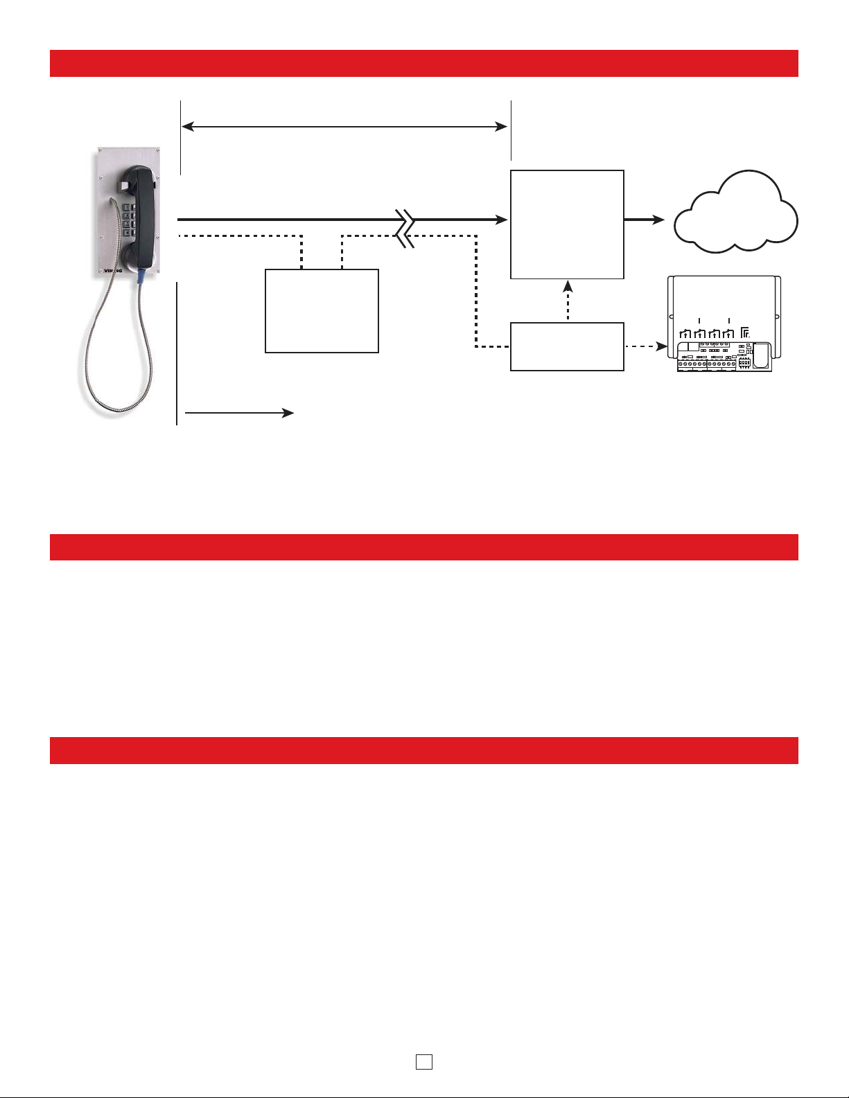
Typical Installation on SIP Based VoIP Phone System
(Extends range of cable, keeps
1 Gbps network speed for other
equipment on network)
SIP VoIP PBX
or
PC with
SIP Server
Software
100m (328 ft) maximum*
Viking supplies
Customer’s
Responsibility
Internet
10/100 Mbps
Maximum
Viking
K-1900-8-IP
VoIP Phone
* Note: A PoE extender can be used for an additional 100 meters per extender. For longer runs (up to 2 km / 1.2 miles)
a ethernet to ber media converter can be used.
Optional
PoE Injector
(If VoIP PBX does
not have PoE)
Optional
Switch / Hub
LED 7LED 5 LED 8LED 6
LED 3LED 2LED 1
LED 9
LED 4
123on4
MAC:
18E80FXXXXXX
asdesaxtff
C NO NC
RL 1
C NO NC
RL 2
C NO NC
RL 3
C NO NC
RL 4
1 2 3 4 NETWORK
1234
NETWORK
VIKING
ELECTRONICS
HUDSON, WI 54016
NETWORK ENABLED
RELAY CONTROLLER
MODEL RC-4A
©
VIKING
1
IN1 C IN2 IN3 C IN4
23456
LOGIC LEVEL
PROGRAMMING
RESTORE DEFAULTS
DEBOUNCE
POW
E
R 12V DC
RELAY 1 RELAY 2 RE LAY 3 RELAY 4
1 2 3 4 5 7 8 9 10 11 126
STATUS
LED
Optional Viking model
RC-4A Secure Remote
Relay Controller, see
page 6 (DOD# 582)
PC Requirements
• IBM compatible personal computer with:
Windows 7, 8 or 10
• Adobe Acrobat Reader 8 or higher
• K-1900-8-IP hardware
Download and install the programming software
PC Programming
1. Go to www.vikingelectronics.com and enter K-1900-8-IP or K-1900-812L-IP in the search box
2. Click K-1900-8-IP or K-1900-812L-IP in the search results
3. Scroll down the page to Downloads, click IP Programming Software
4. Install the programming software by saving or opening the file and then clicking on setup Viking IP
Programming.exe
5. Follow the prompts on your screen to complete software installation.
6. To start the Viking IP Programming application, click on the Viking IP Programming icon on your desk
top. The Main screen will appear, allowing the user to program any K-1900-8-IP Series connected to
that LAN.
Note: PC must be connected to the same LAN as the K-1900-8-IP Series.
• Available LAN with PoE (class 2, <6.5 watts)
• Ethernet cable ( CAT5 min.)
• 1 MB minimum free hard drive space for installation
• 16MB of free physical RAM
6
A. Manually Muting SIP/Network Failure Alarm Beeps (3 beeps repeated every 30 seconds)
With the unit connected and powered (Green LED on and Yellow LED off or blinking) it will output 3 beeps every 30
seconds in the handset of the K-1900-8-IP Series indicating a SIP registration failure, failure to receive an echo reply
from a pinged gateway or Ethernet connection failure. You can manually disable the beeps by pressing and holding the
“,” button for 5 seconds (2 beeps will then be heard) or by clicking the “Mute Alarm Until Next Failure” tab in the Viking
VoIP programming software. The LED will continue to flash allowing you to trouble shoot the failure.
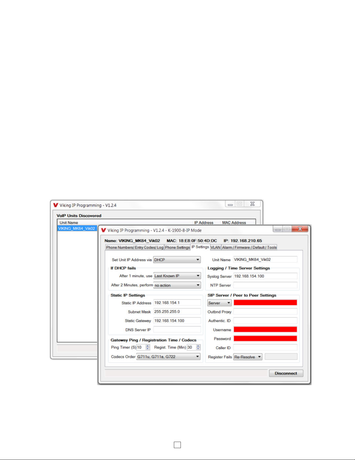
B. Connect / Disconnect
Open the “Viking IP Programming” software on the PC and the start screen shown below will appear. Any Viking IP
phones that are connected to the network will appear on the list. Simply select the K-1900-8-IP Series on the list and
click on the “Connect” button at the bottom or double click the selected phone. If the security code of the selected
phone is still set to default (845464), the PC software will not require entering a security code to connect to the phone.
K-1900-8-IP Series have a default name of “VIKING_MK64_Vik02”, so if many phones are connected to the same
network that all have the default name, MAC addresses must be used to identify each phone.
When finished programming, click on the “Disconnect” button at the bottom. Closing the program will also automatically
disconnect the unit.
7

C. Configuring the K-1900-8-IP Network Settings
Step 1.
Step 2.
Step 3.
Step 4.
Step 5.
Step 6.
Step 7.
Step 8.
Open the “Viking IP Programming” software on a windows PC that is connected to the same LAN as the K-1900-8-IP
Series phone to be programmed.
The window in the upper left corner of the menu will show you each K-1900-8-IP Series phone that is connected to that
LAN. Select the unit with the same MAC address shown on the label located on the top of the Ethernet connector on the
K-1900-8-IP Series phone.
Click the “Connect” button. If a pop up window appears, enter the unit’s security code (factory set to 845464) then click “OK”.
The program will then read and display the K-1900-8-IP Series phone’s IP and programming settings.
Click on the “IP Settings” tab.
Select the appropriate value Static IP Settings or DHCP for “Set Unit IP Address via”. Note: changing the IP address will
cause you to have to reconnect to the unit. Enter the values for the fields in “if DHCP fails” or “Static IP Settings” as needed.
Set the “Unit Name”, “Logging / Time Server Settings” as needed.
Select Peer-Peer in the “SIP Server / Peer to Peer Settings” to use the unit in Peer to Peer mode. Select Server to register
with a SIP registrar server and fill in the “Outbnd Proxy” (SIP Outbound Proxy Server Address, “ip:port”), “Authentic. ID”
(SIP Authentication ID), “Username” (SIP Username, <string>), “Password” (SIP Password), and “Caller ID” (SIP Caller
ID) with values from your VoIP provider.
Example 1: On-Premise SIP
Phone System
(Panasonic TDE 100/200)
Example 2: Cloud Based
Service Provider
(Voip.ms)
8
Example 3: Cloud Based
Service Provider requiring
Outbound Proxy and
Authentication ID (Ring Central)
 Loading...