

Viking hd-1 Service Manual
Telecommunication Peripheral Products
Handset Interfaced
Technical Practice
Touch Tone Dialer
Add Touch Tone Capability to
PABX Consoles
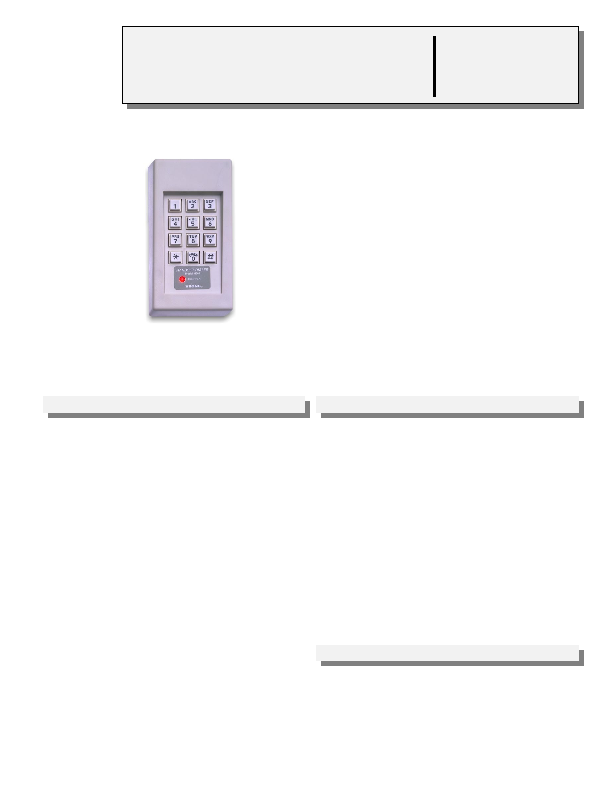
The HD-1 Handset Dialer is a universal keypad
Touch Tone generator capable of providing
DTMF signaling.
The HD-1 permits access via DTMF signaling to
beepers, voice mail and banking services from
phone system consoles or other equipment
which cannot provide Touch Tones. The HD-1 is
easily installed in series with modular handsets
and headsets or interfaces directly to Tip and
Ring.
HD-1
June 1, 1999
http://www.VikingElectronics.com
E-mail...Sales@VikingElectronics.com
VIKING©
Features Applications
• Easily connects in series with handset and
headsets or interfaces directly to Tip & Ring
with the furnished adapter kit
• Provides DTMF signaling across a dry pair
of wires for in-house applications
• Compatible with console phone auxiliary hand set jacks
• Powered by 9 V battery (provided) or optional
PS-1A 13.8V AC adapter
• "Battery O.K." LED indicator
• Add DTMF Signaling to Console Phones for:
1. Beeper paging
2. Voice mail systems
3. Automated attendants
4. Banking services
• Access control (interfaced with an RC-3 or
RC-2A for door/gate control)
Sales...(715) 386 - 8861
• Adjustable Touch Tone volume control
• Switch selectable transmit (per handset wiring
protocol)
• Optional Talk Battery adapter (PS-1A)
Made in the U.S.A.
Specifications
Power: 9 Volt battery provided. Optional Viking PS-1A (120V
AC/13.8V AC 1.25A UL listed adapter)
Battery Life: 1 year average (under normal use)
Dimensions: 152mm x 83mm x 44mm (6” x 3.25” x 1.75”)
Shipping Weight: .90 Kg (2 lbs)
Environmental: 0°C to 32°C (32°F to 90°F) with 5% to 95% non-
condensing humidity
Connections: (1) handset plug, (1) handset jack, optional
connections: (1) RJ11 plug, RJ11 jack
A. Handset Interface
Installation/Programming
ABC DEF
1
23
GHI
JKL MNO
56
4
PRS TUV WXY
789
OPER
#
0
*
HANDSET DIALER
MODEL HD-1
BATTERY OK
VIKING
PABX Console
1 2 3 4 5 6 7 8
10:18
1 2 3 4 5 6 7 8
100
110
120
130
140
150
160
200
210
220
230
240
250
260
1 2 3 4 5 6 7 8
256
1 2 3 4 5 6 7 8
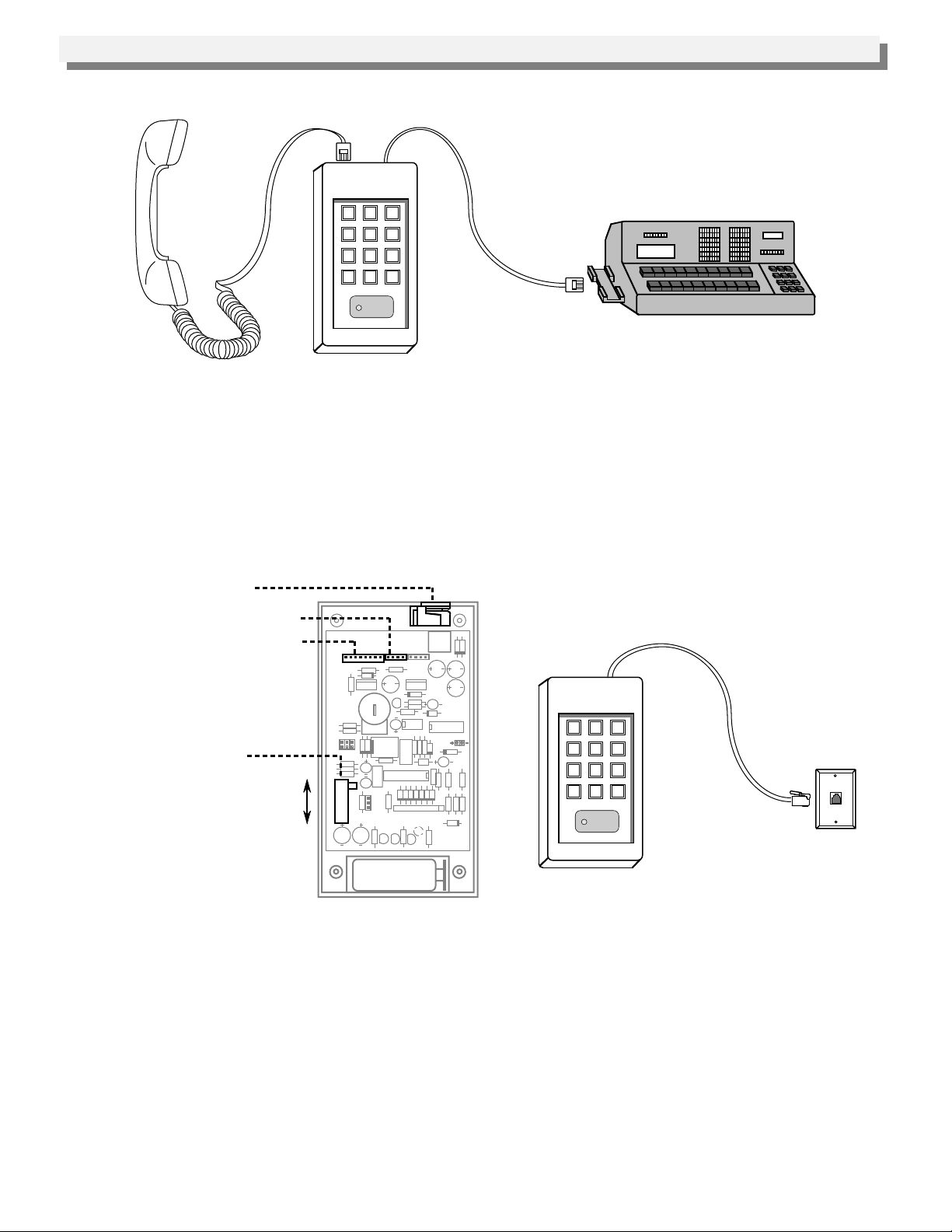
Connect the HD-1 in series with your handset or headset as shown below.
Note: If the handset or headset is terminated with a 5/8” on center twin telephone plug, a modular adapter plug and
socket must be used. Recommended WESTEK part numbers: W478 and PTL-6.
B. Tip & Ring Interface
The HD-1 can be used to dial Touch Tones directly on a Tip & Ring interface (C.O. line, analog PABX/KSU
extension, etc.), it is necessary to change from the default handset cord to the Tip/Ring interface cord.
Modular Handset Jack or
Modular Tip/Ring Jack
J2 Tip/Ring Interface connector
J1 Handset Interface connector
J2
J1
ABC DEF
1
23
GHI
JKL MNO
56
Wiring Protocol switch
S1
A B C
4
PRS TUV WXY
789
OPER
#
0
*
HANDSET DIALER
MODEL HD-1
BATTERY OK
VIKING
1. Locate the Tip/Ring interface cord included in the HD-1 package (6 ft cord with 4 pin connector, RJ11C plug and
jack).
2. Remove the four screws on the back of the HD-1 and remove the cover.
3. Locate J1 (8 pin header on the top of the circuit board) and remove the cord and modular handset jack
connected to J1.
4. Connect the Tip/Ring interface cord to J2.
Note: Connector position 1 to pin 1. Slide the Modular Tip/Ring jack into place.
5. Slide Wiring Protocol switch to position "C.”
6. Replace the back cover and connect the modular cord from the phone to the modular jack on the HD-1.
7. Plug the HD-1 cord into the modular jack the phone was connected to.
 Loading...