


AIR BAND TRANSCEIVER
VXA-700
Operating Manual
SPIRIT

CONTENTS
Important Notice! ........................................................... |
1 |
Introduction .................................................................... |
2 |
Control & Connectors ................................................... |
3 |
Top Panel .............................................................................. |
3 |
Front Panel ........................................................................... |
4 |
Side Panel ............................................................................. |
5 |
Keypad .................................................................................. |
6 |
Before You Begin ........................................................... |
8 |
Precautions ........................................................................... |
8 |
How to Install the Quick Draw Clip ................................... |
8 |
Installation of FNB-80LI Battery Pack .............................. |
9 |
Battery Charging .................................................................. |
9 |
Installation of FBA-23 Alkaline Battery Case ................. |
10 |
Battery Life Information .................................................... |
11 |
AC Operation Using NC-72B/C ....................................... |
11 |
Basic Operation ........................................................... |
12 |
Preliminary Steps ............................................................... |
12 |
Operation Quick Start ........................................................ |
12 |
Squelch Adjustment ........................................................... |
13 |
Accessing the 121.5 MHz Emergency Frequency ........... |
14 |
Tuning Methods ................................................................. |
14 |
Transmission ...................................................................... |
15 |
Reception of Weather Channel Broadcasts ...................... |
16 |
Monitor Key ....................................................................... |
17 |
ANL (Automatic Noise Limiter) Feature ......................... |
17 |
LOCK Function ................................................................. |
18 |
Beep On/Off ....................................................................... |
18 |
Receive Battery Saver Setup ............................................. |
19 |
Memory Operation ....................................................... |
20 |
Memory System Operation ............................................... |
20 |
Memory Storage ................................................................. |
20 |
Recalling the Memories..................................................... |
21 |
Scanning Operation .................................................... |
22 |
Basic Scan .......................................................................... |
22 |
Channel-Skip Scanning ..................................................... |
23 |
Programmable (Band Limit) Memory Scan (PMS) ........ |
23 |
Dual Watch Operation ................................................. |
24 |
Priority Dual Watch Operation ................................... |
25 |
Spectrum Scope Monitor ............................................ |
26 |
Advance Operation (VOR Navigation: AIR Band) ... |
28 |
To Select the VOR Mode .................................................. |
29 |
Flying to a VOR Station .................................................... |
30 |
Entering a Desired Course ................................................ |
32 |
Position Cross-checking .................................................... |
33 |
Split Operation ................................................................... |
34 |
Advanced Operation (Amateur Radio Band) ........... |
35 |
Repeater Operation ............................................................ |
35 |
CTCSS Operation .............................................................. |
37 |
DCS Operation ................................................................... |
39 |
ARTS (Automatic Range Transponder System) Operation ......... |
40 |
Miscellaneous Setting ................................................. |
42 |
Changing the Channel Step ............................................... |
42 |
Changing the Operating Mode .......................................... |
42 |
Automatic Power-Off (APO) Feature) ............................. |
42 |
Transmitter Time-Out Timer (TOT) ................................. |
43 |
Programming the Key Assignments ................................. |
44 |
Display Customization ...................................................... |
45 |
TX/BUSY Indicator Customization ................................. |
46 |
Field Programming Mode ........................................... |
47 |
CPU Resetting .............................................................. |
48 |
Timer Mode ................................................................... |
48 |
Menu (“Set”) Mode ...................................................... |
49 |
Specifications ............................................................... |
60 |
Accessories & Options ............................................... |
62 |
Incase of Difficulty ....................................................... |
64 |

IMPORTANT NOTICE!
FCC RF Exposure Compliance Requirements for Occupational Use Only:
This Radio has been tested and complies with the Federal Communications Commission (FCC) RF exposure limits for Occupational Use/Controlled exposure environment. In addition, it complies with the following Standards and Guidelines:
rFCC 96-326, Guidelines for Evaluating the Environmental Effects of Radio-Frequency Radiation.
rFCC OET Bulletin 65 Edition 97-01 (1997) Supplement C, Evaluating Compliance with FCC Guidelines for Human Exposure to Radio Frequency Electromagnetic Fields.
rANSI/IEEE C95.1-1992, IEEE Standard for Safety Levels with Respect to Human Exposure to Radio Frequency Electromagnetic Fields, 3 kHz to 300 GHz.
rANSI/IEEE C95.3-1992, IEEE Recommended Practice for the Measurement of Potentially Hazardous Electromagnetic Fields - RF and Microwave.
¦This radio is NOT approved for use by the general population in an uncontrolled environment. This radio is restricted to occupational use, work related operations only where the radio operator must have the knowledge to control its RF exposure conditions.
¦When transmitting, hold the radio in a vertical position with its microphone 1 to 2 inches (2.5 to 5 cm) away from your mouth and keep the antenna at least 1 inch (2.5 cm) away from your head and body.
¦The radio must be used with a maximum operating duty cycle not exceeding 50%, in typical Push-to-Talk configurations. DO NOT transmit for more than 50% of total radio use time (50% duty cycle). Transmitting more than 50% of the time can cause FCC RF exposure compliance requirements to be exceeded.
The radio is transmitting when the red LED on the top of the radio is illuminated. You can cause the radio to transmit by pressing the P-T-T button.
¦Always use Vertex Standard authorized accessories.
NOTICE
rThere are no user-serviceable points inside this transceiver. All service jobs must be referred to your Authorized Service Center.
rAmateur Radio License required for operation on Amateur Radio frequencies.
 1
1
VXA-700 SPIRIT OPERATING MANUAL

INTRODUCTION
The Vertex Standard VXA-700 Spirit is a compact, stylish, solid hand-held transceiver providing communication (transmit and receive) capability on the International Aircraft Communication Band (“COM” band: 118 ~ 136.975 MHz), and it additionally provides VOR and CDI navigation features on the “NAV” band (108 ~ 117.975 MHz). What’s more, it also is operational on the Amateur Radio 144 MHz band, for those operators appropriately licensed by the FCC (or the appropriate licensing authority in your country).
The VXA-700 includes Temperature display with our exclusive Omni-Glow™ display back-light for minimal degradation of your night vision, NOAA weather band monitoring, 8-character Alpha/Numeric Display, 102 Memory Channels, and 90 “Book Memory” Channels.
We recommend that you read this manual in its entirety, so as to understand the many features of the VXA-700 completely. Keep this manual handy, so you may use it for reference.
NOTE: The VXA-700’s VOR and CDI Navigation features are supplemental aids to navigation only, and are not intended to be a substitute for accurate (primary) VOR/CDI or landing service equipment.
Congratulations!
You now have at your fingertips a valuable communications tool-a Vertex Standard two-way radio! Rugged, reliable and easy to use, your Vertex Standard radio will keep you in constant touch with your colleagues for years to come, with negligible maintenance down-time.
Please take a few minutes to read this manual carefully. The information presented here will allow you to derive maximum performance from your radio, in case questions arise later on.
We’re glad you joined the Vertex Standard team. Call on us anytime, because communications is our business. Let us help you get your message across.
2 
VXA-700 SPIRIT OPERATING MANUAL
|
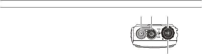
CONTROLS & CONNECTORS (TOP PANEL) |
• Antenna Jack |
• ‚ ƒ |
This SMA jack accepts the supplied flexible antenna, or another antenna designed to provide 50 Ohm impedance on the Aircraft Communication Band and 2- m Amateur Band.
‚ MIC/SP Jack
You may connect the supplied CT-96 Headset Cable,
optional MH-44B4B Speaker/Microphone to this jack. „ Never connect any Speaker/Microphone that is not
recommended by the manufacturer. Because these jack connections are unique, using a Speaker/Microphone that is not specified by Vertex Standard may damage the VXA-700.
ƒ VOL Knob
This control adjusts the audio volume level. Clockwise rotation increases the volume level.
„ DIAL Selector Knob
This 20-position detented rotary switch tunes the operating frequency or selects the memory channels.
 3
3
VXA-700 SPIRIT OPERATING MANUAL
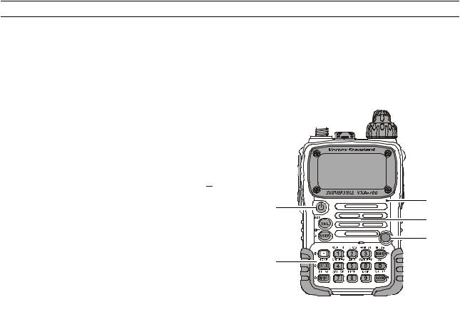
CONTROLS & CONNECTORS (FRONT PANEL)
• LCD (Liquid Crystal Display)
The display shows the current operating conditions, including frequency, etc.
‚ PWR (Power) Switch
Press and hold this switch for 3 seconds to toggle the transceiver’s power on and off.
ƒ Keypad
Several keys have triple functions.
The primary functions are labeled on the key top (activated by simply pressing the key momentarily). The secondary functions are labeled in yellow above the top edge of the key (activated by pressing the  key first, then the indicated key).
The third functions are labeled in black above the top edge of the key (activated by press and holding the indicated key for 2 seconds).
These functions are described in detail on the page 6.
„ BUSY/TX Indicator Lamp
This lamp glows green when a signal is being received and red when transmitting.
You may customize the color setup via the Menu mode.
… Loudspeaker
The internal speaker is located in this position.
† Microphone
Speak across this opening in a normal voice level while pressing the PTT switch, to transmit.
‡ Battery Pack Latch
Open this latch for battery removal.
•

‚ |
† |
|
… |
||
|
||
|
„ |
|
ƒ |
|
‡
4 
VXA-700 SPIRIT OPERATING MANUAL
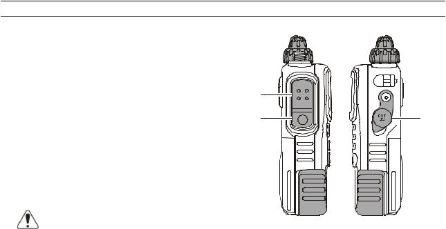
CONTROLS & CONNECTORS (SIDE PANEL)
• PTT (Push To Talk) Switch
Press this button to transmit when you are operating in the COM band or 2-m amateur band. Release this button to return to the “Receive” mode. See page 15.
‚ MONITOR Switch
This button may be pressed to “Open” the squelch manually, allowing you to listen for very weak signals. Press and hold this button for 2 seconds to “Open” the squelch continuously. Press this button again to resume normal (quiet) monitoring. See page 17.
ƒ EXT DC Jack
When an external 12-Volt DC power source is available, you may connect the (optional) E-DC-5B DC Cable w/Noise Filetr or E-DC-6 DC Cable here.
Do not connect any wire to this jack if that wire is connected directly to a 28-Volt DC source. Connecting the VXA-700 directly to a source which exceeds 15.0 Volts DC will result in damage
to the unit.
• |
|
‚ |
ƒ |
 5
5
VXA-700 SPIRIT OPERATING MANUAL
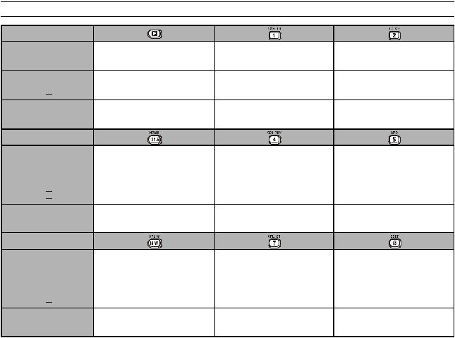
CONTROL & CONNECTORS (KEYPAD)
Primary Function
(Press Key)
Secondary Function (Press +  )
)
Thrid Function (Press and hold key)
Primary Function
(Press Key)
Secondary Function (Press +  )
)
Thrid Function (Press and hold key)
Primary Function
(Press Key)
Secondary Function (Press +  )
)
Thrid Function (Press and hold key)
Activates the “Secondary” key mode.
None
None
Selects the Emergency Channel
(121.5 MHz).
Switches operation to the “Home” (favorite frequency) channel.
None
None
Split-Memory “Write” Command
Memory “Write” Command
Frequency entry digit “1.” |
Frequency entry digit “2.” |
|
Activates VOR mode. |
Selects “TO” VOR mode. |
|
Recalls Menu Item “SQL Type” |
Recalls Menu Item “TONE Set” |
|
(for activating the CTCSS or DCS |
(for selecting the CTCSS tone |
|
operation). |
frequency). |
|
Frequency entry digit “4.” |
Frequency entry digit “5.” |
|
Activates the Course Deviation |
None |
|
Indicator mode. |
||
|
||
Reverse the transmit and receive |
Recalls Menu Item “APO” (for |
|
frequencies while working through |
setting of the Automatic Power- |
|
a repeater. |
Off time). |
|
Frequency entry digit “7.” |
Frequency entry digit “8.” |
|
Activates Split (Duplex) mode. |
None |
|
Recalls Menu Item “Step” (for |
Recalls Menu Item “Beep” (for |
|
setting of the synthesizer steps). |
setting of the keypad beeper). |
6 
VXA-700 SPIRIT OPERATING MANUAL
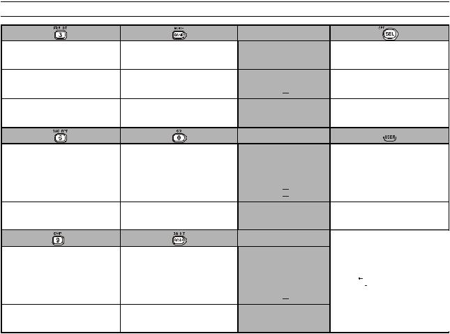
CONTROL & CONNECTORS (KEYPAD)
Frequency entry digit “3.”
Selects “FROM” VOR mode.
Activates the DTMF Autodialer
function.
Frequency entry digit “6.”
Selects the display type (Frequency or Alpha-numeric Tag) during Memory operation.
Select the operation band among the AIR band, Amateur band, and FM BC band in the VFO mode.
Select the operation mode among the AM, FM, and Wide FM.
None
Frequency entry digit “0.”
None
Recalls Menu Item “RPT Shift” (for |
Recalls Menu Item “SQL” (for |
selecting the direction of the uplink |
setting the squelch threshold |
frequency shift during repeater operation). |
level. |
Frequency entry digit “9.” |
Activates the Scanner. |
None |
Activates Dual Watch. |
Sets the Memory Skip (Omit) |
Activates the “Memory Tune” |
feature to the current memory |
mode while in the Memory Recall |
channel. |
mode. |
Primary Function
(Press Key)
Secondary Function (Press +  )
)
Thrid Function (Press and hold key)
Primary Function
(Press Key)
Secondary Function (Press +  )
)
Thrid Function (Press and hold key)
Primary Function
(Press Key)
Secondary Function (Press +  )
)
Thrid Function (Press and hold key)
Select the tuning methods among the VFO, MR, BMR, and WXø1.
Enter the “Set” (Menu) mode.
None

 ø2
ø2
Activate the Automatic Noise
Limiter during AM reception.
Lock the Keypad.
Switches the frequency display between the “Large Character” and “Small Character” mode.
ø1: VFO:Variable Frequency Oscillator MR: Memory Recall BMR:Pre-Programmed Memories WX:Weather Channel Memories
ø2: The Primary and Third function of the  key may be customized by user via the Menu mode. See page 44.
 7
7
VXA-700 SPIRIT OPERATING MANUAL
BEFORE YOU BEGIN
Precautions
¦This apparatus is capable of two-way communication on channels used for critical aviation safety communications. Therefore, it is important that this radio be kept away from children or other unauthorized users at all times.
¦When making DC connections via the (optional) E- DC-5B DC cable, be absolutely certain to observe the proper voltage level and polarity guidelines. Do not connect this radio directly to any 24 ~ 28 Volt DC source, nor to AC power of any kind. Connecting the VXA-700 directly to a source which exceeds 15.0 Volts DC will result in damage to the unit.
¦Do not dispose of the LI-ion Battery Pack in a fire. Do not carry a LI-ion Battery Pack in your pocket, where keys or coins could short the terminals. This could create a serious fire/burn danger, and possibly cause damage to the LI-ion pack.
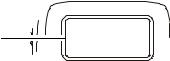
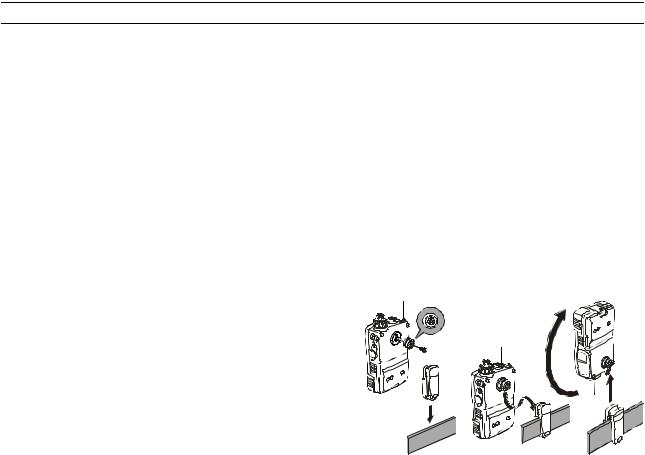
How to Install the Quick Draw Belt Clip
rConnect the hanger to the rear of the VXA-700, with the notch pointing directly up, using the supplied screw (Figure 1). Use only the screw included with the clip to mount the clip to the back of the VXA-700!
rClip the Quick-Draw Belt Clip onto your belt (Figure 2).
rTo install the VXA-700 into the Quick-Draw Belt Clip, align the hanger with the Quick-Draw Belt Clip, and slide the VXA-700 into its slot until a click is heard (Figure 3).
rTo remove the VXA-700 from the Quick-Draw Belt Clip, rotate the VXA-700 180 degrees, then slide the VXA-700 out from the Quick-Draw Belt Clip (Figure 4).
Figure 1
Figure 2 |
Figure 3 |
Figure 4 |
8 
VXA-700 SPIRIT OPERATING MANUAL
BEFORE YOU BEGIN
Installation of FNB-80LI Battery Pack
The FNB-80LI is a high-performance Lithium-Ion battery providing high capacity in a very compact package. Under normal use, the FNB-80LI may be used for approximately 300 charge cycles, after which operating time may be expected to decrease. If you have an old battery pack which is displaying capacity which has become diminished, you should replace the pack with a new one.
rInstall the FNB-80LI as shown in the illustration.
rClose the Battery Pack Latch on the bottom of the radio.
Do not attempt to open any of the rechargeable LI-ion packs, as personal injury or damage to the LI-ion pack could occur if a cell or cells become
accidentally short-circuited.
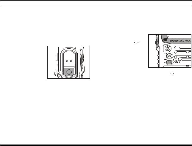
Battery Charging
If the battery has never been used, or its charge is depleted, it may be charged by connecting the NC-72B/C Battery Charger, as shown in the illustration, to the EXT DC jack. If only 12 ~ 16 Volt DC power is 

available, the optional E-DC-5B DC Cable (w/cigarette lighter plug) or E-DC-6 DC Cable may also be used for charging the bat-
tery, as shown in the illustration.
The “Now Charging . . .” will
blink in the display while the battery is being charged. When charging is finished, the display will change to indicate “Complete” and the BUSY/TX indicator will blink blue.
Important Notes:
¦Do not leave the charger connected to the transceiver for continuous periods in excess of 24 hours. Long term overcharging can degrade the LI-ion battery pack and significantly shorten its useful life.
¦If using a charger other than the NC-72B/C, or if using a battery pack other than the FNB-80LI, follow the appropriate instructions provided with the charger/ battery. Contact your Dealer if you have any doubts about the appropriateness of the particular charger or battery pack you intend to use.
 9
9
VXA-700 SPIRIT OPERATING MANUAL

BEFORE YOU BEGIN
Installation of
FBA-23 Alkaline Battery Case (Option)
The optional FBA-23 Battery Case allows receive monitoring using two “AA” size Alkaline batteries.
To Install Alkaline Batteries into the FBA-23 r Slide the batteries into the FBA-23 
as shown in the illustration, with the Negative [–] side of the batteries touching the spring connections in-
side the FBA-23. r Open the Battery Pack Latch on the
bottom of the radio.
r. Install the FBA-23 as shown in the illustration, with the [+] side facing the bottom of the transceiver.
rClose the Battery Pack Latch on the bottom of the radio.
The FBA-23 does not provide connections for charging, since Alkaline cells cannot be re-charged. Therefore, the
NC-72B/C, E-DC-5B, or E-DC-6 may safely be connected to the EXT DC jack when the FBA-23 is installed.
Notes:
¦The FBA-23 is designed for use only with AA-type Alkaline cells.
¦If you do not use the VXA-700 for a long time, remove the Alkaline batteries from the FBA-23, as battery leakage could cause damage to the FBA-23 and/ or the transceiver.
10 
VXA-700 SPIRIT OPERATING MANUAL

BEFORE YOU BEGIN
Low Battery Indication
¦As your battery discharges during use, the voltage will gradually become lower. When the “


 ” icon will blink on the LCD display, the battery pack must be recharged before further use.
¦Avoid recharging Li-Ion batteries before the “Low Battery” indicator is observed, as this can degrade the charge capacity of your Li-Ion battery pack. Vertex Standard recommends that you carry an extra, fullycharged pack with you so you will not lose communications capability due to a depleted Li-Ion battery.
This “deep cycling” practice will help to maintain longer overall battery life after many recharging cycles.
AC Operation Using NC-72B/C (Receiving only)
The VXA-700 may be operated from your house current by use of the supplied NC-72B/C Battery Charger. The NC-72B/C should only be used for reception, because it is not capable of supplying sufficient current to support transmission.
To use the NC-72B/C, turn the transceiver off, then plug the miniature connector of the Battery Charger into the EXT DC jack on the side of the radio. Now plug the Battery Charger into the wall outlet. You may now turn on the transceiver.
11
VXA-700 SPIRIT OPERATING MANUAL
BASIC OPERATION
Preliminary Steps
rInstall a charged battery pack onto the transceiver, as described previously.
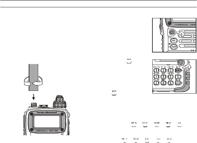
rScrew the supplied antenna onto the Antenna jack. Never operate this transceiver without an antenna connected.
rIf you have an optional Speaker/Microphone or headset. we recommend that it not be connected until you are familiar with the basic operation of the VXA-700.
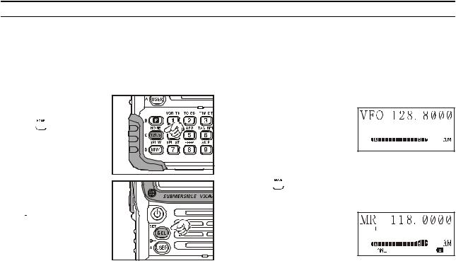
Operation Quick Start
r To turn the radio on, press and hold in the  (PWR) Switch for 3
seconds. r The opening message will appear on the display, then frequency dis-
play will appear.
r Press the  key repetitively, switch the operating band among the AIR band, 2-m Amateur band, and FM BC band each time you press the
 key.
key.
rDirectly entering frequencies from the keypad is the easiest method if you know the frequency on which you wish to operate. Just enter the five digits of the frequency to move to that frequency.
For example, to set 134.35 MHz,
press  Ò
Ò  Ò
Ò  Ò
Ò  Ò
Ò  .
.
To set 118.275 MHz, you do not need to press the final “5” in the frequency:
 Ò
Ò  Ò
Ò  Ò
Ò  Ò
Ò  .
.
12 
VXA-700 SPIRIT OPERATING MANUAL
BASIC OPERATION
Note: When the entered frequency is outside of the current operating band, this feature is ignored (i.e. VXA-700 does not permit entry of a 2-m Amateur band frequency while operating in the AIR band).
r You may also turn the top panel’s DIAL selec-
tor knob to choose the desired operating frequency. The channel frequency will appear on the LCD.
rTo change frequency in 1 MHz steps, press the  key momentarily, then rotate the DIAL selector knob
to select the MHz digit desired. Press the  key once more to resume normal channel step.
rRotate the VOL knob to  set the volume level. If
no signal is present, press and hold in the MONITOR button for 2 seconds; background noise will now be heard,
and you may use this noise to set the VOL knob for the desired audio level. Press the MONITOR button momentarily to silence the noise and resume normal (quiet) monitoring.
rTo turn the radio off, press and hold in the  (PWR) switch for 3 seconds.
Squelch Adjustment
r Press and hold in the |
key for 3 seconds. This in- |
|||
stantly recalls Menu Item |
|
|
|
|
|
|
|
|
|
|
|
|
|
|
“SQL:” on the AM or Nar- |
|
|
|
|
r o w F M m o d e ” o r |
|
|
|
|
“WSQL:” on the WFM |
|
|
|
|
|
|
|
|
|
mode. |
|
|
|
|
rPress the  key to enable adjustment of this Menu Item.
rRotate the DIAL selector knob to set the squelch threshold (0 - 8) so that the receiver is just silenced. A higher number indicates that a higher signal level is required in order to open the squelch.
rWhen you have made your setting, press the  key to save the new setting, then press the PTT key repetitively until the radio exits to normal operation.
13
VXA-700 SPIRIT OPERATING MANUAL
BASIC OPERATION
Accessing the 121.5 MHz Emergency Frequency
The VXA-700 can quickly access the 121.500 MHz Emergency Frequency. This function can be activated even when the keypad lock function is in use.
r To access the Emergency Frequency, press the  key momentarily.
r To exit the Emergency Frequency, press the 

 key momentarily.
Tuning Methods
Throughout this manual, you will see references to several different frequency setting methods. Each will be particularly useful in a particular operating situation, and they are described below:
¦VFO (Variable Frequency Oscillator)
The VFO is a “tuning
dial” system which allows
you to tune through the 


 AIR band, 2-m Amateur


 band, and FM BC band using the DIAL selector, the Keypad, or the scanner. To select these bands, press the
  key momentarily.
¦MR (Memory Recall)
The MR (Memory Re-
call) mode of the VXA700 provides the user
with the ability to store
and recall as many as 102 channels in the radio’s main memory bank. These memory channels may also be labeled by you with an alpha/numeric name of up to 8 characters in length, to aid in quick identification of the channel. See page 20 for details on creating alpha/ numeric labels.
14 
VXA-700 SPIRIT OPERATING MANUAL
BASIC OPERATION
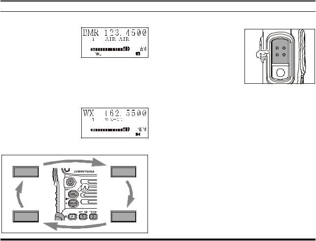
¦ BOOK (Pre-Programmed) Memories
The Book memories are
pre-programmed, either at the factory or by your
Dealer (depending on
your country’s requirements), typically including the major AIR band station frequencies used in your area. The Book memories can be changed by the user. See page 47 for details.
¦ WX (Weather Channel) Memories (USA version only)
Ten Weather Channels
are pre-programmed at
the factory. The VXA700 will automatically
scan this special bank when it is selected by the user.
Transmission
r To transmit, press and hold in the PTT switch. Speak into the micro-
phone area of the front
panel grille in a normal voice level.
r To return to the receive mode, release the PTT switch.
VFO |
MR |
WX |
BOOK |
(USA version only)
15
VXA-700 SPIRIT OPERATING MANUAL
BASIC OPERATION
Reception of Weather Channel Broadcasts (USA version only)
The VXA-700 can receive VHF Weather Channel broadcasts, which may assist your flight planning. The VXA700 includes a ten-channel auto-search feature, which simplifies access to Weather Channels when you are in an unfamiliar location.
r To receive Weather  Channels, press the


 key (repeatedly, if nec-


 essary) to select the


 Weather Channel mode.

 In the Weather Channel


 mode, “WX” will appear
  upper left corner of the display.
rThe VXA-700 will now scan quickly though the ten standard Weather Channels, and will stop on the first active station found.
rIf there are two or more weather channels audible in your area, you may select the alternate channel(s) by pressing the PTT switch. Pressing the PTT switch reinitiates the scanning process.
rIf there are no Weather Channels in your area, the scanner will not stop. Press the MONITOR button to stop the scanner.
rYou can also select Weather Channels manually by rotating the DIAL selector knob.
rTo exit the Weather Channel mode, press the 

 key momentarily to return to the VFO mode.
Note: The Weather Channel mode memorizes the last Weather Channel you have used, and will retain this information until the radio is turned off.
16 
VXA-700 SPIRIT OPERATING MANUAL
BASIC OPERATION
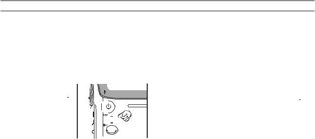
Monitor Key
When listening to a very weak signal from an aircraft or ground station, you may observe the signal disappearing periodically as the incoming signal strength becomes too weak to override the squelch threshold setting.
To disable the squelch temporarily, press and hold the MONITOR key for 2 sec-  onds on the left side of the


 radio, just below the PTT


button. The squelch will remain open and you should
have a better chance of hearing weak signals.
To return to normal operation, press the MONITOR key momentarily.
ANL (Automatic Noise Limiter) Feature
For reduction of impulse noise, such as that produced by an engine’s ignition system, the ANL feature may prove helpful.
r To activate the ANL feature, press the 

 key m o m e n t a r i l y. T h e “ANL” icon will appear on the display, and you should observe a reduction in the ignition noise.
rTo turn the ANL feature off, press the 

 key again; the “ANL” icon will disappear from the display.
17
VXA-700 SPIRIT OPERATING MANUAL
BASIC OPERATION
LOCK Function
The lock function prevents accidental changes to the frequency setting and the keypad controls.
r To activate the lock feature, press  Ò
Ò 

 . r In the LOCK mode, the “

 ” icon will appear on
the display.
r To turn the lock feature off, press  Ò
Ò 

 again.
rYou can still access the 121.500 MHz Emergency Frequency when the LOCK function is on. Simply press
the  key momentarily (this key never locks). Pressing this key also unlocks the radio.
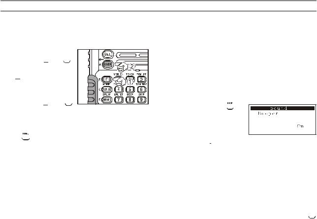
Beep On/Off
The VXA-700’s key/button beeper provides convenient audible feedback whenever a button is pressed. Each key and button has a different beep pitch, and each function has a unique beep combination.
When you are scanning, the beeper will be heard each time the scanner halts on a busy channel. This may be distracting in some environments; if you want to turn the beeper off (or back on again):
r Press and hold the  key for 2 seconds. This instantly recalls Menu Item “Beeper.”
rPress the 

 key to enable adjustment of this Menu Item.
rRotate the DIAL selector knob to select the desired selection.
On: Sounds a keypad beeper corresponding to a musical note.
DTMF: Sounds a keypad beeper corresponding to a DTMF tone.
Off: Keypad beeper is “off.”
rWhen you have made your selection, press the 

 key to save the new setting, then press the PTT key repetitively until the radio exits to normal operation.
18 
VXA-700 SPIRIT OPERATING MANUAL
BASIC OPERATION
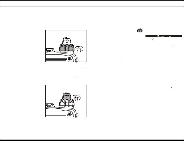
Receive Battery Saver Setup
An important feature of the VXA-700 is its Receive Battery Saver, which “puts the radio to sleep” for a time interval, periodically “waking it up” to check for activity. If somebody is talking on the channel, the VXA-700 will remain in the “active” mode, then resume its “sleep” cycles. This feature significantly reduces quiescent battery drain, and you may change the amount of “sleep” time between activity checks using the Menu System:
rPress the  key, then press the

 key to activate the Menu (“SET”) mode.
rRotate the DIAL selector knob to select Menu Item “3. Receive,” then press the 

 key.
key.
rRotate the DIAL selector knob to select Sub Menu Item “5. RX Save,” then press the 

 key.
key.
rPress the 

 key again to enable adjustment of this Menu Item.
rRotate the DIAL selector knob to select the desired “duty cycle” (receive:sleep). The selections available are 1:1, 1:2, 1:3, 1:4, 1:5, and ABS* or oFF. The default value is 1:1.
rWhen you have made your selection, press the 

 key to save the new setting, then press the PTT key repetitively until the radio exits to normal operation.
*ABS: Automatic Battery Saver, based on activity on the receiver.
The setting of 1:5 will promote the greatest conservation of battery capacity, but the receiver’s response time to incoming calls will be slowed somewhat.
Note: This feature does not operate during Scan or Dual Watch.
19
VXA-700 SPIRIT OPERATING MANUAL
 Loading...