How it Works
Log In / Sign Up
Buy Points
How it Works
FAQ
Contact Us
Questions and Suggestions
Users
Vertex Standard
Loading...
V
VX-131
VX-131 Series
VX-132
2
VX-132 Series
VX-1400
2
VX-1400 series
VX-146
VX-150
2
VX-160
2
VX-160E
VX-160 Series
VX-160U
5
VX-160V
2
VX-170
VX-1700
6
VX-1700 Series
2
VX-170R
VX-177
VX-177R
VX-180
3
VX-180E
VX-180 Series
VX-180U
4
VX-180V
VX-1R
VX-2000R
VX-2000U
VX-2000V
VX-210
VX-2100
6
VX-2100E
VX-2100E Series
VX-2100 Series
5
VX-210A
VX-210AU
VX-2200
7
VX-2200E Series
2
VX-2200 LTR Series
2
VX-2200 series
6
VX-230
3
VX-230 Series
5
VX-231
VX-241PMR446
2
VX-2500
4
VX-2500 Series
4
VX-2500U
5
VX-2500U(A)
VX-2500U(D)
VX-2500U(F)
VX-2500V
6
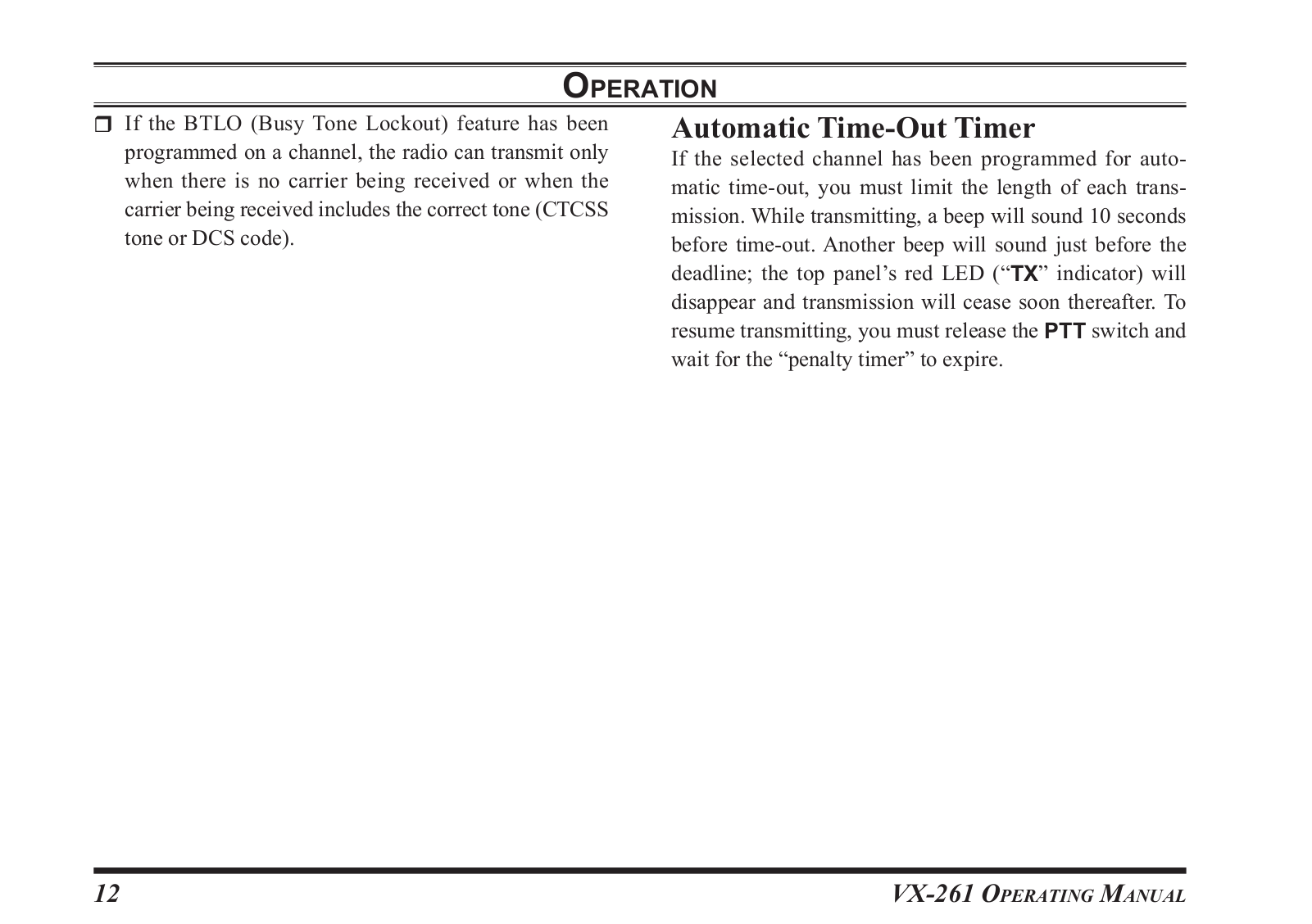
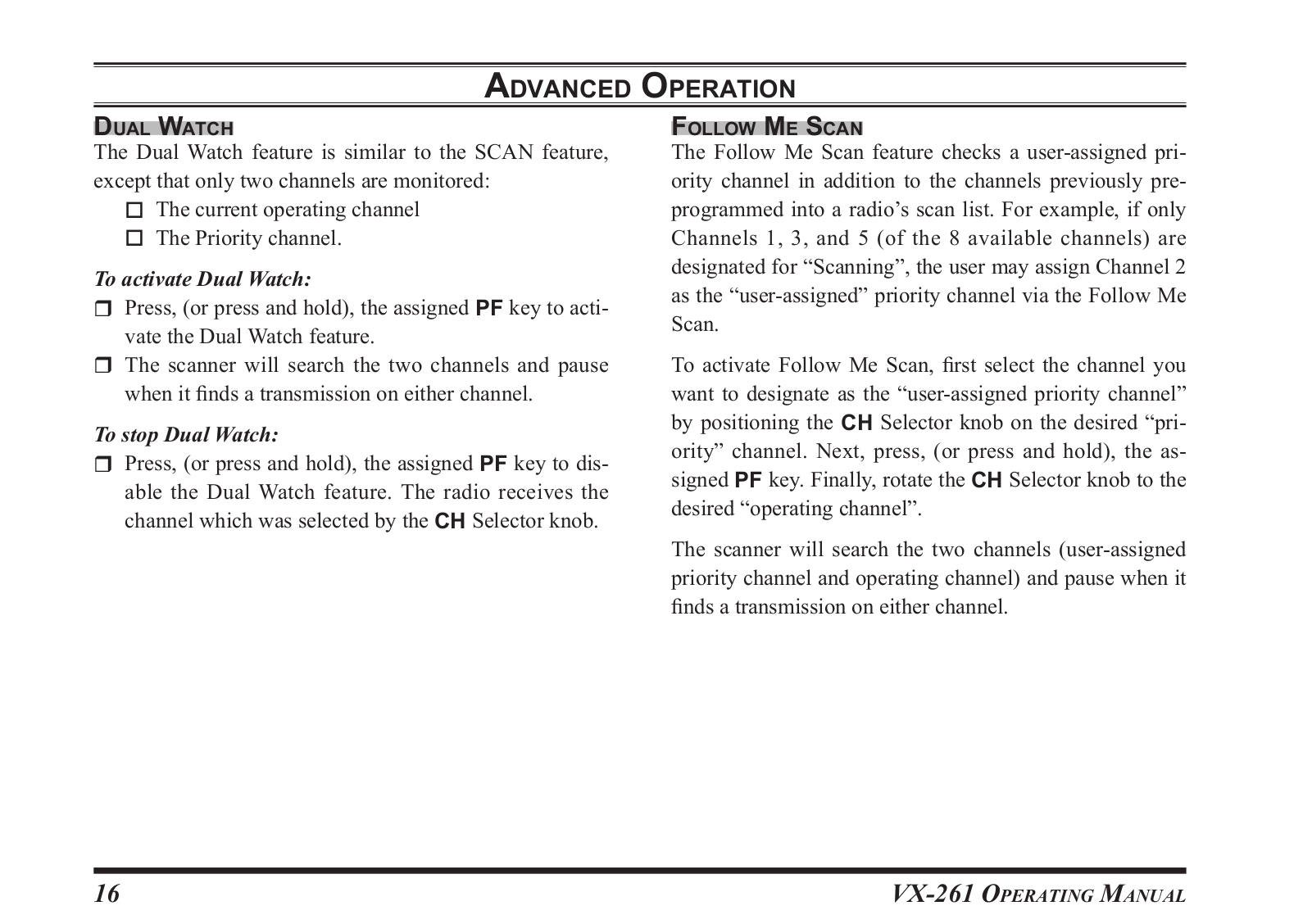
VX-261
2
VX-264
VX-2R
VX-3000
VX-3200
2
VX-3200 Series
VX-3200U
VX-3200U u001f
VX-3200V
2
VX-350
2
VX-350 series
7
Vx-351
3
VX-351-EG3J-1
VX-351PMR446
Vx-354
3
VX-3R
3
VX-4000
2
VX-4000L
2
VX-4000 Series
2
VX-4000U
2
VX-4000V
2
VX-410
2
VX-4100
VX-4100E Series
VX-4100 Series
5
VX-4104
2
VX-4104E
VX-4107
2
VX-4107E
VX-410E series
2
VX-410 Series
5
VX-414
VX-417
VX-420
5
VX-4200
2
VX-4200E Series
VX-4200 Series
6
VX-4204
2
VX-4204E
VX-4207
2
VX-4207E
VX-420A Series
3
VX-420E
VX-420E series
VX-420 Series
7
VX-424
VX-424A
VX-427
VX-427A
VX-450
Loading...
Loading...
Nothing found
VX-261
Service Manual
17 pgs
4.28 Mb
0
User Manual
24 pgs
3.87 Mb
1
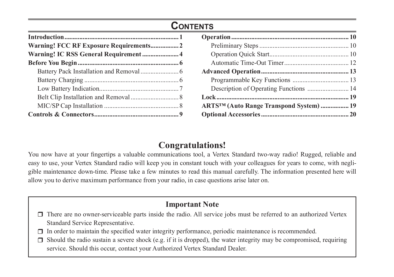
Table of contents
Loading...
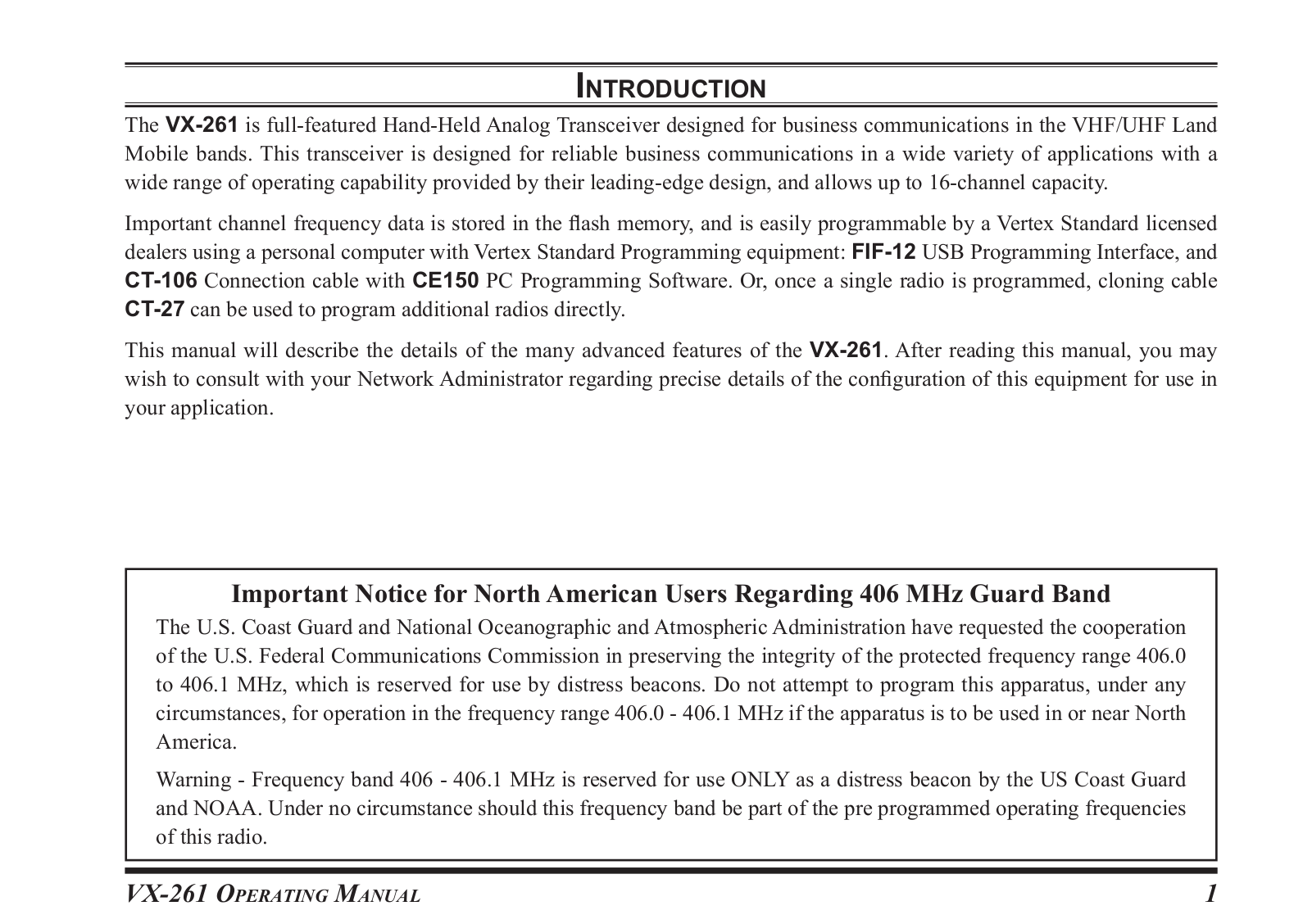
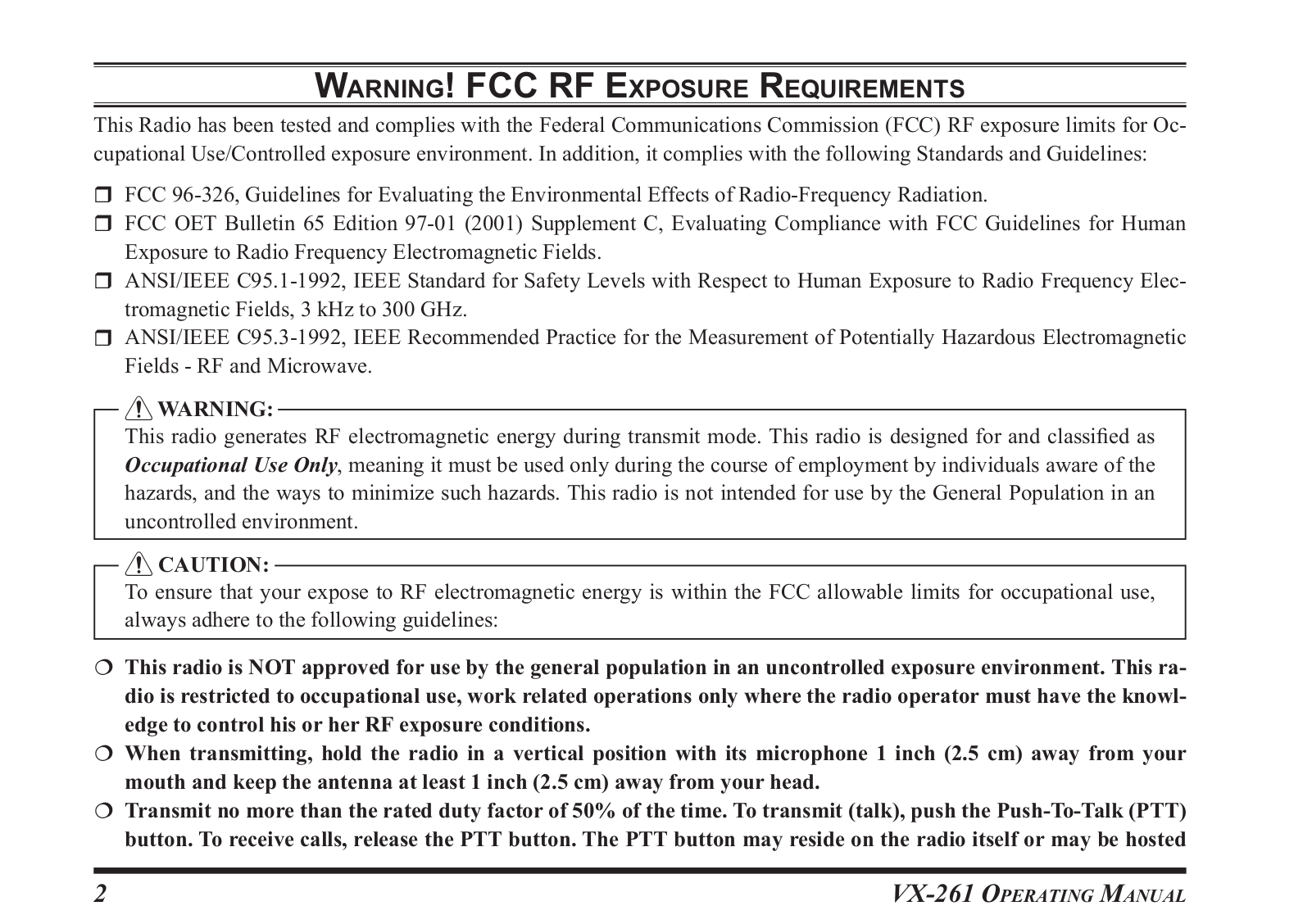
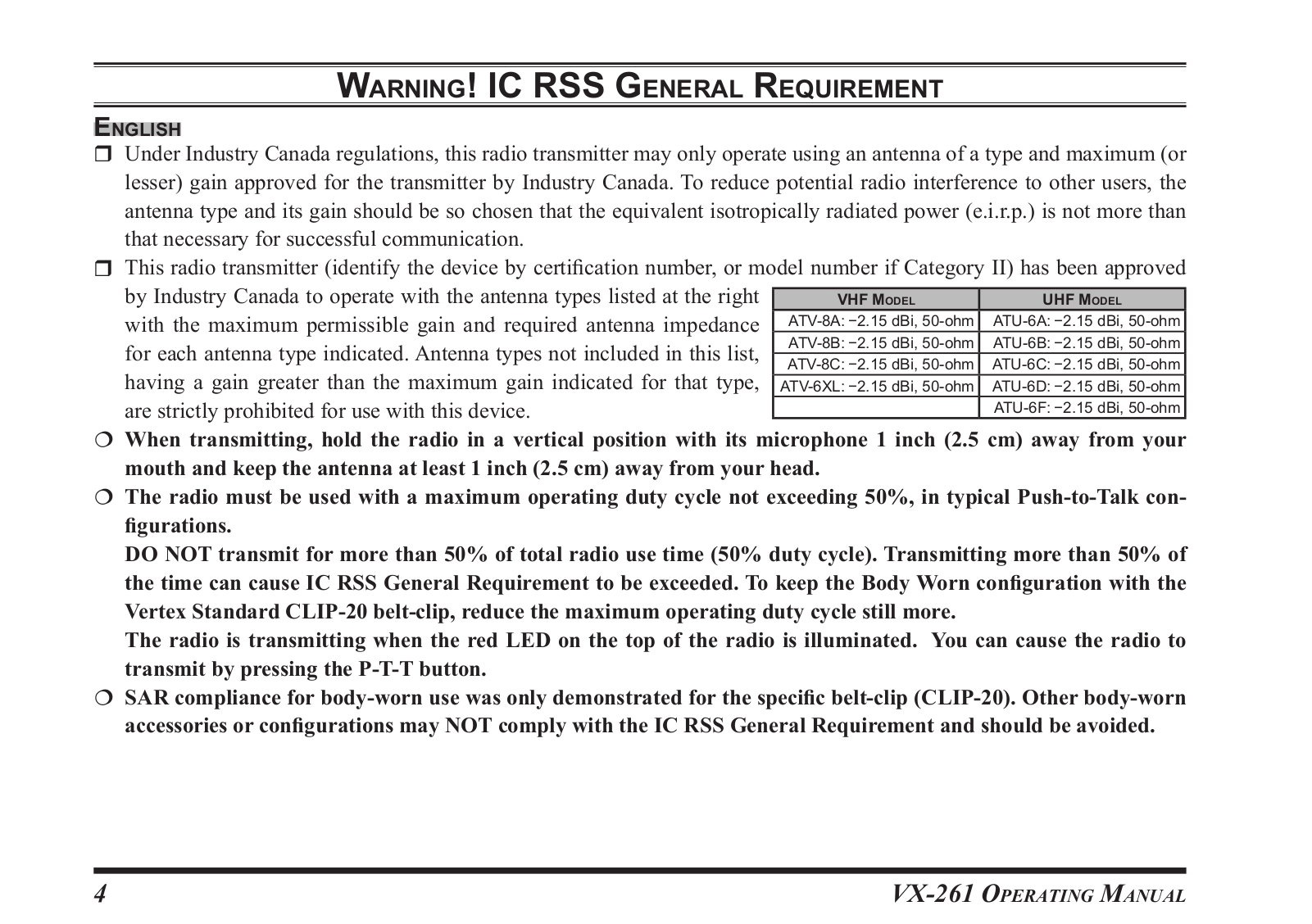
Vertex Standard VX-261 User Manual
...
Vertex Standard User Manual
Download
Specifications and Main Features
Frequently Asked Questions
User Manual
Download
Loading...
+
hidden pages
Unhide
You need points to download manuals.
1 point = 1 manual.
You can buy points or you can get point for every manual you upload.
Buy points
Upload your manuals