


VX-264
Operating Manual
Programmable Functions/Features
IP55 Water Resistant
Six Programmable Function Keys
2-Tone Encode/Decode
5-Tone Encode/Decode
MDC-1200® Encode (ANI Encode)
DTMF Encode
Scan
Group Scan
Dual Watch
Follow-Me Scan
Talk Around Scan
Voice Inversion Encryption
VOX
Talk Around
Emergency
Lone Worker
TX Save Disable
Lock
ARTS™(Auto Range Transpond System)

Contents
......................................................................Introduction |
1 |
........................................................................Operation |
12 |
Warning! FCC RF Exposure Requirements.................. |
2 |
Preliminary Steps....................................................... |
12 |
Warning! IC RSS General Requirement....................... |
4 |
Operation Quick Start................................................ |
12 |
Before You Begin.............................................................. |
6 |
Automatic Time-Out Timer....................................... |
14 |
Battery Pack Installation and Removal........................ |
6 |
Advanced Operation...................................................... |
15 |
Battery Charging.......................................................... |
6 |
Programmable Key Functions .................................. |
15 |
Low Battery Indication................................................ |
7 |
Description of Operating Functions .......................... |
18 |
Belt Clip Installation and Removal.............................. |
8 |
Lock................................................................................. |
27 |
MIC/SP Cap Installation.............................................. |
8 |
ARTS™ (Auto Range Transpond System).................. |
27 |
Controls & Connectors.................................................. |
10 |
Optional Accessories...................................................... |
28 |
LCD Icons & Indicators................................................ |
11 |
|
|
Congratulations!
You now have at your fingertips a valuable communications tool, a Vertex Standard two-way radio! Rugged, reliable and easy to use, your Vertex Standard radio will keep you in constant touch with your colleagues for years to come, with negligible maintenance down-time. Please take a few minutes to read this manual carefully. The information presented here will allow you to derive maximum performance from your radio, in case questions arise later on.
Important Note
rThere are no owner-serviceable parts inside the radio. All service jobs must be referred to an authorized Vertex Standard Service Representative.
rIn order to maintain the specified water integrity performance, periodic maintenance is recommended.
rShould the radio sustain a severe shock (e.g. if it is dropped), the water integrity may be compromised, requiring service. Should this occur, contact your Authorized Vertex Standard Dealer.

Introduction
The VX-264 is full-featured Hand-Held Analog Transceiver designed for business communications in the VHF/UHF Land Mobile bands. This transceiver is designed for reliable business communications in a wide variety of applications with a wide range of operating capability provided by their leading-edge design, and allows up to 128-channel capacity within a maximum 8 groups. Each channel can be programmed with an 8-character Alpha-Numeric Tag.
Important channel frequency data is stored in the flash memory, and is easily programmable by a Vertex Standard licensed dealers using a personal computer with Vertex Standard Programming equipment: FIF-12 USB Programming Interface, and CT-106 Connection cable with CE150 PC Programming Software. Or, once a single radio is programmed, cloning cable CT-27 can be used to program additional radios directly.
This manual will describe the details of the many advanced features of the VX-264. After reading this manual, you may wish to consult with your Network Administrator regarding precise details of the configuration of this equipment for use in your application.
Important Notice for North American Users Regarding 406 MHz Guard Band
The U.S. Coast Guard and National Oceanographic and Atmospheric Administration have requested the cooperation of the U.S. Federal Communications Commission in preserving the integrity of the protected frequency range 406.0 to 406.1 MHz, which is reserved for use by distress beacons. Do not attempt to program this apparatus, under any circumstances, for operation in the frequency range 406.0 - 406.1 MHz if the apparatus is to be used in or near North America.
Warning - Frequency band 406 - 406.1 MHz is reserved for use ONLY as a distress beacon by the US Coast Guard and NOAA. Under no circumstance should this frequency band be part of the pre programmed operating frequencies of this radio.
VX-264 Operating Manual |
1 |
Warning! FCC RF Exposure Requirements
This Radio has been tested and complies with the Federal Communications Commission (FCC) RF exposure limits for Occupational Use/Controlled exposure environment. In addition, it complies with the following Standards and Guidelines:
FCC 96-326, Guidelines for Evaluating the Environmental Effects of Radio-Frequency Radiation.
FCC OET Bulletin 65 Edition 97-01 (2001) Supplement C, Evaluating Compliance with FCC Guidelines for Human Exposure to Radio Frequency Electromagnetic Fields.
ANSI/IEEE C95.1-1992, IEEE Standard for Safety Levels with Respect to Human Exposure to Radio Frequency Electromagnetic Fields, 3 kHz to 300 GHz.
ANSI/IEEE C95.3-1992, IEEE Recommended Practice for the Measurement of Potentially Hazardous Electromagnetic Fields - RF and Microwave.

 WARNING:
This radio generates RF electromagnetic energy during transmit mode. This radio is designed for and classified as Occupational Use Only, meaning it must be used only during the course of employment by individuals aware of the hazards, and the ways to minimize such hazards. This radio is not intended for use by the General Population in an uncontrolled environment.

 CAUTION:
To ensure that your expose to RF electromagnetic energy is within the FCC allowable limits for occupational use, always adhere to the following guidelines:
This radio is NOT approved for use by the general population in an uncontrolled exposure environment. This radio is restricted to occupational use, work related operations only where the radio operator must have the knowledge to control his or her RF exposure conditions.
When transmitting, hold the radio in a vertical position with its microphone 1 inch (2.5 cm) away from your mouth and keep the antenna at least 1 inch (2.5 cm) away from your head.
Transmit no more than the rated duty factor of 50% of the time. To transmit (talk), push the Push-To-Talk (PTT) button. To receive calls, release the PTT button. The PTT button may reside on the radio itself or may be hosted
2 |
VX-264 Operating Manual |

Warning! FCC RF Exposure Requirements
on approved accessories. Transmitting 50% of the time, or less, is important because this radio generates measurable RF energy exposure only when transmitting (in terms of measuring for standards compliance).
The radio is transmitting when the red LED on the top of the radio is illuminated. You can cause the radio to transmit by pressing the P-T-T button.
In front of the face. Hold the radio in a vertical position with the microphone (and other parts of the radio including the antenna) at least 1 inch (2.5 cm) away from the nose or lips. Keeping the radio at a proper distance is important to ensure compliance.
SAR compliance for body-worn use was only demonstrated for the specific belt-clip (CLIP-20). Other body-worn accessories or configurations may NOT comply with the FCC RF exposure requirements and should be avoided.
Always use Vertex Standard authorized accessories.
The information listed above provides the user with the information needed to make him or her aware of RF exposure, and what to do to assure that this radio operates with the FCC RF exposure limits of this radio.
Electromagnetic Interference/Compatibility
During transmissions, this radio generates RF energy that can possibly cause interference with other devices or systems. To avoid such interference, turn off the radio in areas where signs are posted to do so.
Do not operate the transmitter in areas that are sensitive to electromagnetic radiation such as hospitals, health care facilities, aircraft, and blasting sites.
VX-264 Operating Manual |
3 |

Warning! IC RSS General Requirement
English
rUnder Industry Canada regulations, this radio transmitter may only operate using an antenna of a type and maximum (or lesser) gain approved for the transmitter by Industry Canada. To reduce potential radio interference to other users, the antenna type and its gain should be so chosen that the equivalent isotropically radiated power (e.i.r.p.) is not more than that necessary for successful communication.
rThis radio transmitter (identify the device by certification number, or model number if Category II) has been approved
by Industry Canada to operate with the antenna types listed at the right with the maximum permissible gain and required antenna impedance for each antenna type indicated. Antenna types not included in this list, having a gain greater than the maximum gain indicated for that type, are strictly prohibited for use with this device.
VHF Model |
UHF Model |
ATV-8A: −2.15 dBi, 50-ohm |
ATU-6A: −2.15 dBi, 50-ohm |
ATV-8B: −2.15 dBi, 50-ohm |
ATU-6B: −2.15 dBi, 50-ohm |
ATV-8C: −2.15 dBi, 50-ohm |
ATU-6C: −2.15 dBi, 50-ohm |
ATV-6XL: −2.15 dBi, 50-ohm |
ATU-6D: −2.15 dBi, 50-ohm |
|
ATU-6F: −2.15 dBi, 50-ohm |
When transmitting, hold the radio in a vertical position with its microphone 1 inch (2.5 cm) away from your mouth and keep the antenna at least 1 inch (2.5 cm) away from your head.
The radio must be used with a maximum operating duty cycle not exceeding 50%, in typical Push-to-Talk configurations.
DO NOT transmit for more than 50% of total radio use time (50% duty cycle). Transmitting more than 50% of the time can cause IC RSS General Requirement to be exceeded. To keep the Body Worn configuration with the Vertex Standard CLIP-20 belt-clip, reduce the maximum operating duty cycle still more.
The radio is transmitting when the red LED on the top of the radio is illuminated. You can cause the radio to transmit by pressing the P-T-T button.
SAR compliance for body-worn use was only demonstrated for the specific belt-clip (CLIP-20). Other body-worn accessories or configurations may NOT comply with the IC RSS General Requirement and should be avoided.
4 |
VX-264 Operating Manual |

Warning! IC RSS General Requirement
French
rConformément à la réglementation d’Industrie Canada, le présent émetteur radio peut fonctionner avec une antenne d’un type et d’un gain maximal (ou inférieur) approuvé pour l’émetteur par Industrie Canada. Dans le but de réduire les risques de brouillage radioélectrique à l’intention des autres utilisateurs, il faut choisir le type d’antenne et son gain de sorte que la puissance isotrope rayonnée quivalente (p.i.r.e.) ne dépassepas l’intensité nécessaire à l’établissement d’une communication satisfaisante.
rLe présent émetteur radio (identifier le dispositif par son numéro de certification ou son numéro de modèle s’il fait par-
tie du matériel de catégorie I) a été approuvé par Industrie Canada pour fonctionner avec les types d’antenne énumérés dans le droit et ayant un gain admissible maximal et l’impédance requise pour chaque type d’antenne. Les types d’antenne non inclus dans cette liste, ou dont le gain est supérieur au gain maximal indiqué, sont strictement interdits pour l’exploitation de l’émetteur.
VHF Modèle |
UHF Modèle |
ATV-8A: −2.15 dBi, 50-ohm |
ATU-6A: −2.15 dBi, 50-ohm |
ATV-8B: −2.15 dBi, 50-ohm |
ATU-6B: −2.15 dBi, 50-ohm |
ATV-8C: −2.15 dBi, 50-ohm |
ATU-6C: −2.15 dBi, 50-ohm |
ATV-6XL: −2.15 dBi, 50-ohm |
ATU-6D: −2.15 dBi, 50-ohm |
|
ATU-6F: −2.15 dBi, 50-ohm |
Pour émettre, tenez votre radio verticalement en plaçant le microphone entre 2,5 cm de la bouche. L’antenne doit toujours être à plus de 2,5 cm de votre tête.
Le temps total d’émission de la radio ne doit pas dépasser 50% du temps de fonctionnement dans une configuration normale avec alternat. Par conséquent, vous ne devez PAS émettre pendant plus de 50% du temps total d’utilisation de la radio. Si cette règle n’est pas respectée, vous exposez à un dépassement de l’exposition aux fréquences électromagnétiques telle que définie par la norme de sécurité. La radio émet lorsque le voyant LED rouge (situé au sommet de la radio) est allumé. Vous pouvez déclencher l’émission en appuyant sur le bouton Alternat ou avec un micro-casque VOX, si la radio permet d’utiliser cet accessoire.
La conformité SAR pour utilisation sur le corps n’a été confirmée que pour l’attache ceinture de nomenclature CLIP-20. L’utilisation de tout autre accessoire pour port sur le corps PEUT être non conforme aux normes d’exposition aux radio-fréquences et doit donc être évitée.
N’opérez pas votre radio en mode d’émission lorsque vous la portez fixée sur le corps à l’aide de l’accessoire suivant : CLIP-20 attache ceinture.
VX-264 Operating Manual |
5 |
Before You Begin
Battery Pack Installation and Removal
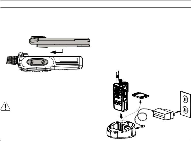
To install the battery pack, align the battery pack to the radio with an offset about 1/2 inch (1.5 cm) from the top edge of battery compartment, then slide the battery pack upward until it locks in place with a “Click.”
To remove the battery, turn the radio off and remove any protective cases. Slide the Battery Pack Latch on the bottom of the radio toward the front panel while sliding the battery down about 1/2 inch (1.5 cm). Then lift the battery out from the radio.
Do not attempt to open any of the rechargeable Lithium-Ion packs, as they could explode if ac-
cidentally short-circuited.
Battery Charging
Remove the Spacer Plate from the nest of the optional CD-58 Desktop Charger, if the Battery Spacer is installed.
Insert the DC plug from the optional PA-55 AC Adapter into the DC jack on the rear panel of the optional CD-58 Desktop Charger, and then connect the PA-55 AC Adapter to the AC line outlet.
Insert the battery pack into the CD-58 Desktop Charger while aligning the slots of the battery pack with the guides in the nest of the CD-58; refer to the following illustration for details on proper positioning of the
Spacer Plate |
AC Line Outlet |
|
PA-55
CD-58
6 |
VX-264 Operating Manual |
Before You Begin
battery pack. If charging with the transceiver attached, turn the transceiver off. The antenna jack should be at the left side when viewing the charger from the front.
If the battery pack is inserted correctly, the LED indicator will glow red. A fully-discharged battery pack will charge completely in 1.5 - 3.0 hours (depending on the battery pack being charged).
When charging is completed, the LED indicator will change to green.
Disconnect the battery pack from the CD-58 Desktop Charger and unplug the PA-55 AC Adapter from the AC line outlet.
1) Always use the Vertex Standard FNB-V133LI- UNI or FNB-V134LI-UNI Lithium-Ion Battery
Pack.
2)Use only the Vertex Standard CD-58 Desktop Charger and the Vertex Standard PA-55 AC Adapter.
3)To reduce the risk of explosion, recharge the batteries outside of hazardous locations.
4)Perform the battery charging where the ambient temperature range +41 °F to +104 °F (+5 °C to +40 °C). Charging outside of this temperature range could cause damage to the battery pack.
5)Battery Pack should not be exposed to excessive heat such as sunshine, fire, or similar heat sources.
6)Risk of explosion exists if battery is replaced by an incorrect type. Refer to the enclosed instructions for disposal of used batteries.
7)For further details and cautions of the charging, refer to the Operating Manual of the CD-58 Desktop Charger.
Low Battery Indication
As the battery discharges during use, the voltage gradually becomes lower. When the battery voltage becomes too low, substitute a freshly charged battery and recharge the depleted pack. The LED indicator on the top of the radio will blink red when the battery voltage is low.
You may confirm the battery condition by the Battery Icon on the display. See page 11 for more information.
 CAUTION
Danger of explosion if battery is replaced with an incorrect battery. Replace only with the same or equivalent type.
VX-264 Operating Manual |
7 |

Before You Begin
Belt Clip Installation and Removal
To install the Belt Clip: align the Belt Clip to the groove of the Battery pack, then press the Belt Clip downward until it locks in place with a “Click.”
To remove the Belt Clip: use a flat head screw driver to press the Belt Clip Tab away from the battery pack to unlock the Belt Clip, then slide the Belt Clip upward to remove it.
Belt Clip Tab 
MIC/SPCAPInstallation
Install the MIC/SP cap with the supplied screws.
Use only the supplied screws when install the MIC/SP cap.
This radio does not keep the Water Resistant Rating (IP55) when the MIC/SP cap is not installed in the MIC/SP jack.
8 |
VX-264 Operating Manual |
 Loading...