

Page 1
VX 820
Installation Guide
C
V
O
E
N
R
F
T
I
I
F
D
E
M
O
E
L
P
N
N
A
T
T
E
E
R
IA
A
EV
L
4
.
VeriFone Part Number DOC282-003-EN-A, Revision A.5
Page 2

VX 820 Installation Guide
© 2010 VeriFone, Inc.
All rights reserved. No part of the contents of this document may be reproduced or transmitted in any form without the written
permission of VeriFone, Inc.
The information contained in this document is subject to change without notice. Although VeriFone has attempted to ensure the
accuracy of the contents of this document, this document may include errors or omissions. The examples and sample programs are
for illustration only and may not be suited for your purpose. You should verify the applicability of any example or sample program
before placing the software into productive use. This document, including without limitation the examples and software programs, is
supplied “As-Is.”
VeriFone, the VeriFone logo, Omni, VeriCentre, Verix, and ZonTalk are registered trademarks of VeriFone. Other
brand names or trademarks associated with VeriFone’s products and services are trademarks of VeriFone, Inc.
All other brand names and trademarks appearing in this manual are the property of their respective holders.
Comments? Please e-mail all comments in this document to your local VeriFone Support Team.
VeriFone, Inc.
2099 Gateway Place, Suite 600
San Jose, CA, 95110 USA
www.verifone.com
VeriFone Part Number DOC282-003-EN-A, Revision A.5
Page 3

CHAPTER 1
Overview
CHAPTER 2
Setup Select Location . . . . . . . . . . . . . . . . . . . . . . . . . . . . . . . . . . . . . . . . . . . . . . . . . . . 9
V
O
C
CONTENTS
PREFACE . . . . . . . . . . . . . . . . . . . . . . . . . . . . . . . . . . . . . . . 3
Audience. . . . . . . . . . . . . . . . . . . . . . . . . . . . . . . . . . . . . . . . . . . . . . . . . . . . . . . . 3
Organization . . . . . . . . . . . . . . . . . . . . . . . . . . . . . . . . . . . . . . . . . . . . . . . . . . . . . 3
Related Documentation . . . . . . . . . . . . . . . . . . . . . . . . . . . . . . . . . . . . . . . . . . . . 3
Guide Conventions. . . . . . . . . . . . . . . . . . . . . . . . . . . . . . . . . . . . . . . . . . . . . . . . 4
Acronym Definitions . . . . . . . . . . . . . . . . . . . . . . . . . . . . . . . . . . . . . . . . . . . . 5
VX 820 . . . . . . . . . . . . . . . . . . . . . . . . . . . . . . . . . . . . . . . . . . . . . . . . . . . . . . . . . 7
Features at a Glance . . . . . . . . . . . . . . . . . . . . . . . . . . . . . . . . . . . . . . . . . . . . . . 7
Features and Benefits . . . . . . . . . . . . . . . . . . . . . . . . . . . . . . . . . . . . . . . . . . . . . 8
N
O
E
L
IA
T
Ease of Use . . . . . . . . . . . . . . . . . . . . . . . . . . . . . . . . . . . . . . . . . . . . . . . . . . 9
Environmental Factors . . . . . . . . . . . . . . . . . . . . . . . . . . . . . . . . . . . . . . . . . . 9
R
Electrical Considerations . . . . . . . . . . . . . . . . . . . . . . . . . . . . . . . . . . . . . . . 10
E
Unpack Shipping Carton. . . . . . . . . . . . . . . . . . . . . . . . . . . . . . . . . . . . . . . . . . . 10
Examine
VX 820 Features. . . . . . . . . . . . . . . . . . . . . . . . . . . . . . . . . . . . . . . . . . . . . . . . . 11
MSAM / Micro SD Cards . . . . . . . . . . . . . . . . . . . . . . . . . . . . . . . . . . . . . . . . . . 12
N
Cable Connections . . . . . . . . . . . . . . . . . . . . . . . . . . . . . . . . . . . . . . . . . . . . . . . 14
Power Supply . . . . . . . . . . . . . . . . . . . . . . . . . . . . . . . . . . . . . . . . . . . . . . . . . . . 17
Smart Card Reader Use . . . . . . . . . . . . . . . . . . . . . . . . . . . . . . . . . . . . . . . . . . . 18
Magnetic Card Reader Use . . . . . . . . . . . . . . . . . . . . . . . . . . . . . . . . . . . . . . . . 18
Contactless Transactions . . . . . . . . . . . . . . . . . . . . . . . . . . . . . . . . . . . . . . . . . . 19
Optional Accessories . . . . . . . . . . . . . . . . . . . . . . . . . . . . . . . . . . . . . . . . . . . . . 20
F
Connection to another VeriFone Terminal . . . . . . . . . . . . . . . . . . . . . . . . . . 14
RS232 Connection using an External Power Brick. . . . . . . . . . . . . . . . . . . . 15
Direct USB Connection . . . . . . . . . . . . . . . . . . . . . . . . . . . . . . . . . . . . . . . . . 15
USB–Download Support using an External Power Brick . . . . . . . . . . . . . . . 15
PoweredUSB connection . . . . . . . . . . . . . . . . . . . . . . . . . . . . . . . . . . . . . . . 16
Ethernet Connection with External Power Brick . . . . . . . . . . . . . . . . . . . . . . 17
To Conduct a Credit/Debit Card Transaction . . . . . . . . . . . . . . . . . . . . . . . . 18
Using the VX 820 for Contactless Transactions . . . . . . . . . . . . . . . . . . . . . . 19
Privacy Shield . . . . . . . . . . . . . . . . . . . . . . . . . . . . . . . . . . . . . . . . . . . . . . . . 20
Stylus and Holder . . . . . . . . . . . . . . . . . . . . . . . . . . . . . . . . . . . . . . . . . . . . . 20
F
I
D
I
P
M
E
T
E
L
N
A
T
E
R
EV
A
5
.
CHAPTER 3
Specifications Unit Power Requirements. . . . . . . . . . . . . . . . . . . . . . . . . . . . . . . . . . . . . . . 21
Power Pack. . . . . . . . . . . . . . . . . . . . . . . . . . . . . . . . . . . . . . . . . . . . . . . . . . 21
Temperature . . . . . . . . . . . . . . . . . . . . . . . . . . . . . . . . . . . . . . . . . . . . . . . . . 21
Humidity . . . . . . . . . . . . . . . . . . . . . . . . . . . . . . . . . . . . . . . . . . . . . . . . . . . . 21
External Dimensions . . . . . . . . . . . . . . . . . . . . . . . . . . . . . . . . . . . . . . . . . . . 21
Weight. . . . . . . . . . . . . . . . . . . . . . . . . . . . . . . . . . . . . . . . . . . . . . . . . . . . . . 21
Processor . . . . . . . . . . . . . . . . . . . . . . . . . . . . . . . . . . . . . . . . . . . . . . . . . . . 21
VX 820 INSTALLATION GUIDE 1
Page 4

Memory . . . . . . . . . . . . . . . . . . . . . . . . . . . . . . . . . . . . . . . . . . . . . . . . . . . . . 21
Display . . . . . . . . . . . . . . . . . . . . . . . . . . . . . . . . . . . . . . . . . . . . . . . . . . . . . 21
Magnetic Card Reader . . . . . . . . . . . . . . . . . . . . . . . . . . . . . . . . . . . . . . . . . 21
Primary Smart Card . . . . . . . . . . . . . . . . . . . . . . . . . . . . . . . . . . . . . . . . . . . 21
SAM Card Reader. . . . . . . . . . . . . . . . . . . . . . . . . . . . . . . . . . . . . . . . . . . . . 21
Keypad . . . . . . . . . . . . . . . . . . . . . . . . . . . . . . . . . . . . . . . . . . . . . . . . . . . . . 22
Peripheral Ports . . . . . . . . . . . . . . . . . . . . . . . . . . . . . . . . . . . . . . . . . . . . . . 22
Security . . . . . . . . . . . . . . . . . . . . . . . . . . . . . . . . . . . . . . . . . . . . . . . . . . . . . 22
CHAPTER 4
Maintenance and
Cleaning
CHAPTER 5
Service and Support Service Returns . . . . . . . . . . . . . . . . . . . . . . . . . . . . . . . . . . . . . . . . . . . . . . . . . 25
CHAPTER 6
Troubleshooting
Guidelines
V
Clean the PIN Pad. . . . . . . . . . . . . . . . . . . . . . . . . . . . . . . . . . . . . . . . . . . . . . . 23
Card Readers . . . . . . . . . . . . . . . . . . . . . . . . . . . . . . . . . . . . . . . . . . . . . . . . . . . 23
Accessories Accessories and Documentation . . . . . . . . . . . . . . . . . . . . . . . . . . 27
Supplementary Hardware . . . . . . . . . . . . . . . . . . . . . . . . . . . . . . . . . . . . . . . 27
Data Cables . . . . . . . . . . . . . . . . . . . . . . . . . . . . . . . . . . . . . . . . . . . . . . . . . 27
Power Supply . . . . . . . . . . . . . . . . . . . . . . . . . . . . . . . . . . . . . . . . . . . . . . . . 27
USB Power Cable . . . . . . . . . . . . . . . . . . . . . . . . . . . . . . . . . . . . . . . . . . . . . 27
O
F
I
R
Blank Display . . . . . . . . . . . . . . . . . . . . . . . . . . . . . . . . . . . . . . . . . . . . . . . . . . . 29
Keypad Does Not Respond . . . . . . . . . . . . . . . . . . . . . . . . . . . . . . . . . . . . . . . . 29
E
Transactions Fail To Process. . . . . . . . . . . . . . . . . . . . . . . . . . . . . . . . . . . . . . . 30
D
I
E
N
N
E
T
L
IA
F
C
O
N
T
E
M
P
L
A
T
E
R
EV
A
4
.
2 VX 820 INSTALLATION GUIDE
Page 5

PREFACE
This guide is the primary source of information for setting up and installing the VX
820.
Audience
Organization
V
O
Related
Documentation
C
This guide describes the VX 820 features, and provides the basic information for
its installation and configuration.
This guide is organized as follows:
Chapter 1, Overview. Provides an overview of the VX 820.
Chapter 2, Setup. Explains setup and installation of the VX 820, selecting a
location, and establishing connections with other devices.
E
L
N
Chapter 3, Specifications. Discusses power requirements and dimensions of the
VX 820.
F
Chapter 4, Maintenance and Cleaning. Explains maintenance of the VX 820.
R
Chapter 5, Service and Support. Provides information on contacting your
VeriFone service provider and information on how to order accessories or
E
documentations from VeriFone.
I
D
I
O
N
E
IA
T
F
Chapter 6, Troubleshooting Guidelines. Provides troubleshooting guidelines
N
should you encounter a problem in terminal installation and configuration.
5
To learn more about the VX 820, refer to the following set of documents:
• Vx820 Certifications and Regulations Sheet, VPN - DOC282-001-EN-A
• Vx820 Quick Installation Guide, VPN - DOC282-002-EN-A.
• Vx820 Reference Guide, VPN - DOC282-004-EN-A.
• Verix eVo Volume I: Operating System Programmers Manual, VPN -
DOC00301.
E
R
V
S
I
I
N
O
.
A
• Verix eVo Volume II: Operating System and Communication Programmers
Manual, VPN - DOC00302.
• Verix eVo Volume III: Operating System Programming Tools Reference
Manual, VPN - DOC00304.
VX670 INSTALLATION GUIDE 3
Page 6

PREFACE
NOTE
CAUTION
WARNING
Guide Conventions
Guide
Conventions
E
V
Various conventions are used to help you quickly identify special formatting.
Table 1 describes these conventions and provides examples of their use.
Table 1 Document Conventions
Convention Meaning Example
Blue Text in blue indicates terms that
are cross references.
Italics Italic typeface indicates book
titles or emphasis.
The pencil icon is used to
highlight important information.
The caution symbol indicates
hardware or software failure, or
loss of data.
O
N
E
IA
See Guide Conventions.
You must not use this unit
underwater.
RS232-type devices do not work
on the VX 820 communication
port.
L
The unit is not waterproof or
dustproof, and is intended for
indoor use only.
T
R
I
F
The lighting symbol is used as a
warning when bodily injury might
occur.
D
E
N
Due to risk of shock do not use
the terminal near water.
I
F
C
O
N
R
E
V
4
.
A
N
O
I
S
I
4 VX 820 INSTALLATION GUIDE
Page 7

PREFACE
Guide Conventions
Acronym Definitions
V
Various acronyms are used in place of the full definition. Table 2 presents
acronyms and their definitions.
Table 2 Acronym Definitions
Acronym Definitions
AES Advanced Encryption Standard Algorithm
DUKPT Derived Unique Key Per Transaction Method as defined in the
VISA’s POS Equipment Requirement: PIN processing and Data
Authentication, International Version 1.0, August 1988
ECR Electronic Cash Register
EMV Joint Europay, MasterCard and Visa Standard
MSAM Multiple Secure Access Module
OS Operating System
PIN Personal Identification Number
POS Point-of-Sale
RFID Radio Frequency Identification
SAM Secure Access Module
SC Smart Card (Integrated Chip Card)
SD Secure Digital
R
SR Ship Release
E
SRAM Static Random Access Memory
UI User Interface
F
USB Universal Serial Bus
N
F
I
D
I
O
E
N
N
E
T
L
IA
C
O
R
E
V
5
.
A
N
O
I
S
I
X
V
670 INSTALLATION GUIDE 5
Page 8

PREFACE
Guide Conventions
C
V
O
E
N
R
F
I
I
F
D
R
O
E
V
E
N
N
S
I
T
O
I
E
N
IA
.
A
L
4
6 VX 820 INSTALLATION GUIDE
Page 9
Overview
CHAPTER 1
This chapter provides a brief description of VeriFone’s VX 820.
VX 820
V
Features at a
Glance
O
C
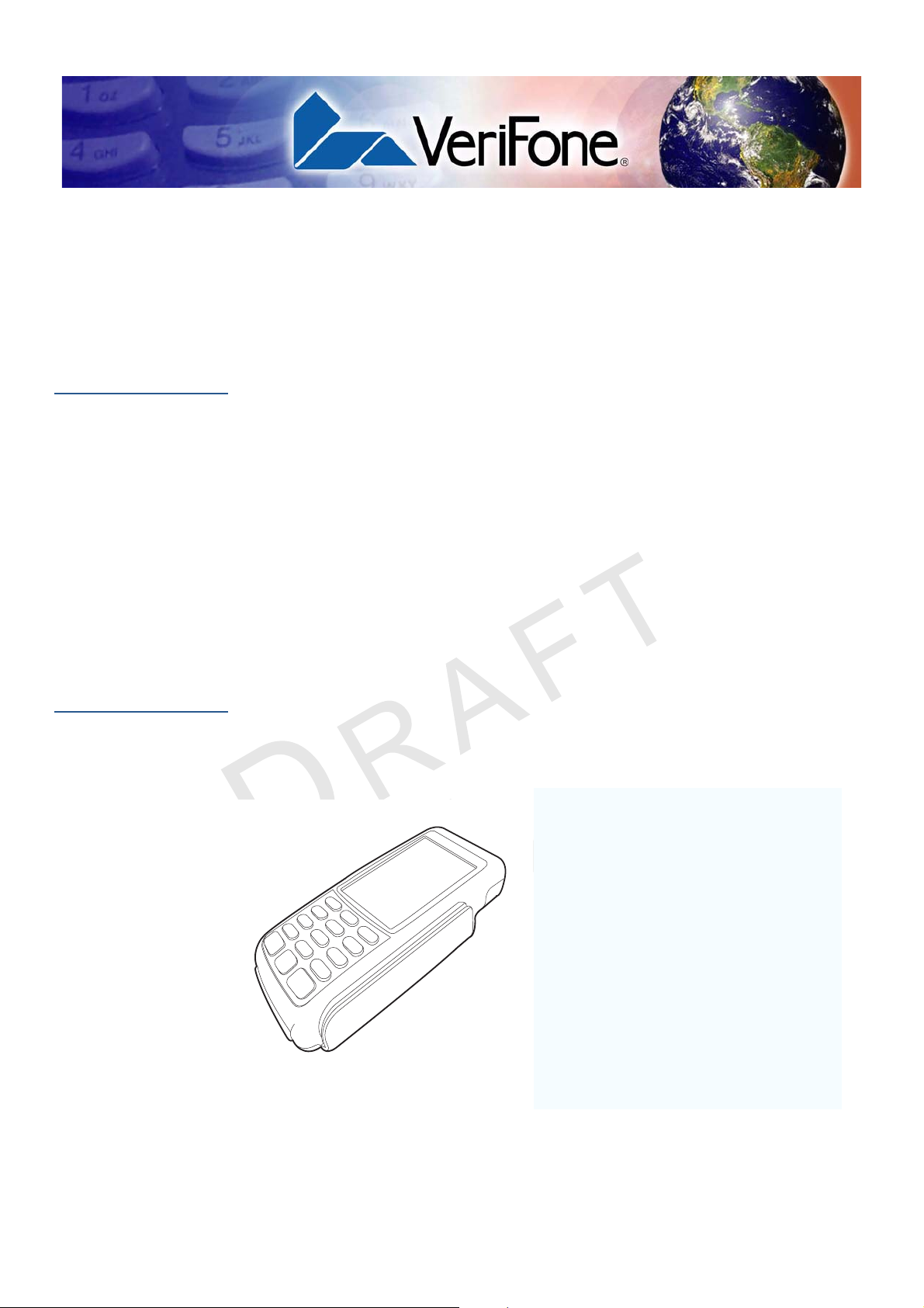
The VX 820 takes the most usable and ergonomic hand-held PIN pad payment
device and takes it to a new level by adding a color touchscreen display, a larger
keypad, and integrated contactless capability. It is designed to fit in a variety of
payment environments to suit nearly any need. With VeriFone’s patent-pending
MAXui design, enhanced with a robust 3.5” color QVGA display, and larger blue
backlit keys, the device is easy to use under any lighting conditions. A tapered
design and ergonomically balanced midpoint help the VX 820 fit comfortably in
even the smallest hands, and the rugged design holds up to the most demanding
conditions.
F
O
I
The VX 820 is a programmable device, allowing a custom or EMV-approved
R
transaction application to run from the PCI PED 3.0-compliant PIN pad, either to
E
meet local regulatory requirements or relieve the ECR or terminal of this task.
The VX 820 has a sleek and stylish ergonomic design that offers power and
N
performance in a smart card- and MSR-integrated PIN pad device. The VX 820
provides the right combination of features and functions in a sleek, stylish device
that fits in the palm of your hand. This includes a magnetic stripe card reader,
smart card reader, an integrated PIN pad, and optional integrated contactless
F
D
I
E
N
N
I
V
E
R
S
T
O
I
E
L
IA
5
.
A
N
• Displays vibrant colors and comes
with a touchscreen interface ideal
for large and small retailers
• Integrated contactless option
• PCI PED 3.0 approved
• EMV Level 1 and 2 Type Approved,
offering the most reliable security
available, including SSL and
VeriShield file authentication, and
VeriShield Protect to help prevent
fraud.
.
Figure 1 VX 820 with new handheld design
VX 820 INSTALLATION GUIDE 7
Page 10

OVERVIEW
Features and Benefits
Features and
Benefits
E
V
O
C
Exceptional Ease of Use
• Bold, ergonomic design is sleek, stylish, and lightweight for conveniently
handing the unit to the consumer for PIN entry or other input
• Intuitive telco-style interface with large, colored control keys and optionally 4
soft-function keys as well as 4 screen-addressable keys via touchscreen
simplify training and reduce support requests
• 240 x 320 pixel color TFT (QVGA) display that supports up to 26 lines x 26
characters and handles multiple languages for global applications
Critical Security Protection
• Incorporates tamper-detection circuitry to resist unauthorized intrusion and
supports a broad spectrum of software-based security features
• Integrated security modules simultaneously support sophisticated encryption
(AES, DES, 3DES, RSA) and key management schemes, including single and
3DES Master Session, single, and 3DES Derived
O
N
E
IA
L
T
Strong Feature Set
• Ensures uncompromising reliability from VeriFone, the worldwide leader in
R
e-payment
I
F
D
N
E
I
• Primary smart card reader support for synchronous and asynchronous smart
F
cards
N
• Support for international character sets and Unicode standard
4
• Received EMV Level 1 and Level 2 approval for smart card solutions
• Offers the most reliable security available, including SSL, VeriShield file
authentication, and VeriShield Protect to help prevent fraud and other
intrusions
S
I
I
N
O
V
Extended PIN pad Capabilities
• Optional privacy shield
E
R
.
A
8 VX 820 INSTALLATION GUIDE
• Patent-pending MAXui design, enhanced with a robust 3.5” color QVGA
display, and larger blue backlit keys, makes it easy to use under any lighting
condition
• Triple-track, high-coercivity, bi-directional card reader handles most magnetic
stripe cards
• Three Security Access Modules (SAMs) safeguard sensitive financial data
and support multiple smart card schemes
• Integrated contactless option
• PCI PED 3.0 approved for PIN-based debit transactions
• Can be powered by other Vx series terminals through a single multi-port
connector which supports RS-232, USB 2.0 device, USB Host, and Ethernet
Page 11

Setup
CAUTION
Select Location
C
Ease of Use
V
O
CHAPTER 2
This chapter describes the setup procedure for the VX 820, in the following
sections:
• Select Location
• Unpack Shipping Carton
• Examine VX 820 Features
• MSAM / Micro SD Cards
E
L
N
• Cable Connections
O
• Cable Connections
• Power Supply
R
• Smart Card Reader Use
E
• Magnetic Card Reader Use
• Contactless Transactions
N
• Optional Accessories
Use the following guidelines to select a location for the VX 820.
• Select a location convenient for both merchant and cardholder.
• Select a flat support surface, such as a countertop or table.
• Select a location near a power outlet and the terminal, ECR, or computer
F
connected to the VX 820. For safety, do not string cables or cords across a
walkway.
I
I
F
D
R
E
V
E
N
S
I
I
T
O
IA
A
N
5
.
Environmental
Factors
• Do not use the unit where there is high heat, dust, humidity, moisture, or
caustic chemicals or oils.
• Keep the unit away from direct sunlight and anything that radiates heat, such
as a stove or a motor.
• Do not use the VX 820 outdoors.
The VX 820 is not waterproof or dustproof, and is intended for indoor use only.
Any damage to the unit from exposure to rain or dust can void any warranty.
VX 820 INSTALLATION GUIDE 9
Page 12

SETUP
WARNING
WARNING
Unpack Shipping Carton
Electrical
Considerations
Unpack
Shipping Carton
E
V
O
C
• Avoid using this product during electrical storms.
• Avoid locations near electrical appliances or other devices that cause
excessive voltage fluctuations or emit electrical noise (for example, air
conditioners, electric motors, neon signs, high-frequency or magnetic security
devices, or computer equipment).
• Do not use the VX 820 near water or in moist conditions.
Due to risk of shock or damage, do not use the VX 820 near water, including a
bathtub, wash bowl, kitchen sink or laundry tub, in a wet basement, or near a
swimming pool.
Open the shipping carton and carefully inspect its contents for possible tampering
or shipping damage. The VX 820 is a secure product and any tampering can
cause it to cease to function or to operate in an unsecured manner.
1 Remove and inspect the contents of the shipping carton, since the VX 820
ships in multiple configurations, the carton may include any or all of the
following:
F
O
I
• VX 820
R
• Data cable
• Power pack
D
I
E
N
N
E
T
L
IA
F
N
• Power cord
• ECR cable
5
• Privacy shield
2 Remove all plastic wrapping from the terminal and components.
3 Remove the clear protective film from the display.
4 Save the shipping carton and packing material for future repacking or moving
of the device.
E
R
V
S
I
I
N
O
.
A
10 VX 820 INSTALLATION GUIDE
Do not use a unit that has been tampered with or damaged.
The VX 820 comes equipped with tamper-evident labels. If a label or component
appears damaged, please notify the shipping company and your VeriFone
service provider immediately.
Page 13

SETUP
TOUCH-SCREEN
TELCO KEYPAD
COLOR-CODED
FUNCTION KEYS
MAGNETIC CARD
READER
SMART CARD
READER
DISPLAY
Examine VX 820 Features
Examine
VX 820 Features
V
Before you continue with the installation process, familiarize yourself with the VX
820 features:
E
L
N
O
IA
T
F
I
R
E
Figure 2 VX 820 Features
The VX 820 includes the following features:
N
F
D
I
N
E
C
O
• A touch-screen display.
• Three color-coded function keys below the keypad (CANCEL [RED],
BACKSPACE [YELLOW], ENTER [GREEN]).
• A magnetic card reader, built into the right side. An icon shows the
proper swipe direction, with the stripe facing down and towards the
keypad.
E
V
S
I
I
N
O
A
5
.
R
• A smart card reader, built into the unit’s front side. An icon indicates the
proper card position and insertion direction.
• A SAM (Security Access Module) compartment, built into the back side
of the unit. The VX 820 contains multiple-SAM (MSAM) cardholders to
support multiple stored-value card programs or other merchant card
requirements.
• An optional Micro SD Card slot built into the back side of the unit.
X
V
670 INSTALLATION GUIDE 11
Page 14

SETUP
CAUTION
NOTE
MSAM / Micro SD Cards
MSAM / Micro
SD Cards
To change or install
MSAMs
V
You may need to install one or more multiple security access module (MSAM)
cards or replace the old cards.
Observe standard precautions in handling electrostatically sensitive devices.
Electrostatic discharges can damage the equipment. VeriFone recommends
using a grounded anti-static wrist strap.
1 Remove the data cable from the back of the unit.
2 Place the VX 820 facedown on a soft, clean surface to protect the lens from
scratches.
3 Loosen the retaining screw. The restraining screw is captive, which means
that it cannot be fully removed from the slot.
E
L
N
O
IA
T
E
F
I
R
D
I
N
E
F
C
O
N
Figure 3 VX 820 Compartment Door and Locking Screw
5
4 Slide out the compartment door. The MSAM cardholders are now accessible.
Each cardholder consists of a slot inboard of a numbered tray.
S
I
V
E
I
N
O
R
Figure 4 Opening VX 820 Compartment Door
Before inserting the MSAM card, position it as shown in Figure 5, with the card’s
gold contacts facing away from you, toward the unit. The cardholder slot in the
VX 820 has a set of contacts. The MSAM card has a notch on one corner to
ensure that it fits into the connector base in only one way; the VX 820 has a
matching notch cast into the backside of the MSAM compartment door to ensure
the MSAM card is positioned correctly when the cover is closed.
.
A
12 VX 820 INSTALLATION GUIDE
Page 15

MSAM / Micro SD Cards
5 Install the MSAM card by aligning the card to match the embossed number
and carefully sliding it into the slots until fully inserted.
Figure 5 MSAM Insertion
SETUP
To change or install a
Micro SD Card
V
O
C
1 Follow steps 1-4 for opening the VX 820 compartment door.
E
L
N
2 Insert the Micro SD card directly into the slot across the MSAM card holders.
O
IA
T
E
F
I
R
D
I
N
E
F
N
5
.
A
Figure 6 Inserting a Micro SD Card
3 Close the VX 820 compartment door after inserting/replacing the necessary
cards and tighten the locking screw.
E
V
S
I
R
I
N
O
Figure 7 Closed VX 820 Compartment
X
V
670 INSTALLATION GUIDE 13
Page 16

SETUP
CAUTION
Cable Connections
Cable
Connections
Connection to
another VeriFone
Terminal
V
The VX 820 has six general cabling scenarios, depending on what the VX 820
connects to:
1 Connection to another VeriFone Terminal
2 RS232 Connection using an External Power Brick
3 Direct USB Connection
4 USB–Download Support using an External Power Brick
5 PoweredUSB connection
6 Ethernet Connection with External Power Brick
Using an incorrectly rated power supply can damage the unit or cause it not to
work properly. Use only a power pack with VPN PWR282-001-01-A (see
Specifications for detailed power supply specifications).
E
L
N
The VX 820 connects to a VeriFone terminal via a straight cable. There is a
minimum power requirement for the VX 820, currently specified as 4.2W. In cases
where the terminal is only able to provide a 7 V DC output to power the VX 820,
the terminal must be able to source at least 0.57 A of current. Otherwise, proper
R
functioning of the VX 820 is not guaranteed.
E
F
I
D
I
O
N
E
IA
T
F
C
O
N
5
.
A
N
O
I
S
I
V
E
Figure 8 VX 820 Connected to Another VeriFone Terminal
R
14 VX 820 INSTALLATION GUIDE
Page 17

SETUP
Cable Connections
RS232 Connection
using an External
Power Brick
Direct USB
Connection
V
A special dongle cable is used, where one end of the cable plugs into the VX 820
while the other end terminates in a DB-9 connector housing. On the housing, a
DC jack is provided to connect to an external power brick. This is a generic cable
for all RS232-based hosts.
Figure 9 VX 820 with an RS232 Connection Using an External Power
Brick
O
Similarly, a dongle cable is required in standard USB environments. For this cable
option, the host end has a molded housing which exposes the standard USB plug.
R
E
F
I
E
D
I
N
IA
T
N
E
L
F
O
C
USB–Download
Support using an
External Power
Brick
N
5
.
A
N
S
I
O
Figure 10 Direct USB Connection
This cable option comes with a junction box that provides a mini-style Type B
USB socket for connecting to the USB-based host and a DC jack for external
power connection.
In addition, a Type A USB socket is provided on the junction box to support
application download via a USB thumb drive.
E
R
I
V
Figure 11 VX 820 Connected to a USB with Download Support
X
V
670 INSTALLATION GUIDE 15
Page 18

SETUP
A
C
B
CAUTION
Cable Connections
PoweredUSB
connection
V
For a USB-based host with PoweredUSB feature, a straight cable is all that is
required. The VX 820 supports the 12 V DC option.
Figure 12 PoweredUSB Connection
Use the DC jack provided on the USB power cable to connect to an external
power brick. Connect the cable to the VX 820 and plug the male USB connector
into the corresponding USB port on the USB host as illustrated in Figure 10.
N
O
E
L
IA
T
E
F
I
R
D
I
N
E
F
C
O
N
Figure 13 USB Power Cable Connections
N
Using an incorrectly rated power supply can damage the unit or cause it not to
work properly. Use only a power pack with PWR282-001-01-A (see
Specifications for detailed power supply specifications).
E
I
V
S
I
O
R
A
5
.
16 VX 820 INSTALLATION GUIDE
Page 19

SETUP
CAUTION
WARNING
NOTE
Power Supply
Ethernet
Connection with
External Power
Brick
Power Supply
V
The cable required junction box that provides a standard RJ-45 LAN socket and a
DC jack. However, since most hosts do not support peer-to-peer LAN connection
to a PIN pad, an additional RJ-45 socket is provided on the junction box to allow a
direct connection between VX 820 and the host.
Figure 14 Ethernet Connection with External Power Brick
E
L
N
Not all VX 820 configurations and device contexts require the use of a power
supply – VeriFone ships power supplies with the VX 820 as required.
F
If you have changed the context in which the VX 820 is used or have questions
about which power supply should be used, contact your VeriFone representative.
R
E
Using an incorrectly rated power supply can damage the unit or cause it not to
work properly. Use only a power pack with VPN PWR282-001-01-A (see
Specifications for detailed power supply specifications).
N
I
D
I
F
O
N
E
IA
T
C
O
Before connecting a power supply, disconnect the power pack cord from the
power outlet.
Connect and route all cables between the VX 820, ECR, and PC before plugging
the power pack cord into a wall outlet or surge protector.
S
I
I
N
O
A
5
.
V
Do not plug the power pack into an outdoor outlet or operate the VX 820
outdoors. Also, disconnecting power during a transaction can cause transaction
data files not yet stored in memory to be lost.
To protect against possible damage caused by lightning strikes and electrical
surges, VeriFone recommends installing a power surge protector.
When the VX 820 has power and an application is loaded, the application starts
after the initial VeriFone copyright screen and displays a unique copyright screen.
If no application is loaded,
initial VeriFone copyright screen.
E
R
DOWNLOAD NEEDED appears on the display after the
X
V
670 INSTALLATION GUIDE 17
Page 20

SETUP
CAUTION
Smart Card Reader Use
Smart Card
Reader Use
To Conduct a Smart
Card Transaction
V
The smart card transaction procedure can vary depending on the application.
Verify the proper procedure with your application provider before performing a
smart card transaction.
1 Position the smart card with the gold contacts facing upward (see Figure 15).
2 Insert it into the smart card reader slot in a smooth, continuous motion until it
seats firmly.
3 Remove the card when the display indicates the transaction is completed.
E
L
N
O
IA
T
F
I
Figure 15 Smart Card Reader Use
R
E
Leave the smart card in the card reader until the transaction is completed.
F
Premature removal can void the transaction.
D
I
N
E
N
Magnetic Card
Reader Use
C
To Conduct a Credit/
O
Debit Card
Transaction
The VX 820 has a magnetic card reader that uses a triple track stripe reader. This
gives the unit greater reliability over a wide range of swipe speeds and operating
environments.
1 Position a magnetic card with the stripe facing the keypad.
2 Swipe it through the magnetic card reader.
E
V
S
I
I
N
O
A
5
.
R
Figure 16 Magnetic Card Reader Use
18 VX 820 INSTALLATION GUIDE
Page 21

SETUP
Contactless Transactions
Contactless
Transactions
Using the VX 820 for
Contactless
Transactions
V
The VX 820 supports contactless transactions through an integrated contactless
module.
The VX 820 only becomes active for contactless smart card transactions when
initialized by an application.
To perform a contactless smart card transaction:
1 Gently tap the card onto or hold the card (within to 4 cm.) against the surface
of the display.
2 An activated LED visual on the display accompanied by a short beeping sound
indicates a successful transaction.
E
L
N
O
IA
T
E
F
I
R
D
I
N
E
F
C
N
O
Figure 17 Contactless Reader Use
V
E
R
5
.
A
N
O
I
S
I
X
V
670 INSTALLATION GUIDE 19
Page 22

SETUP
Optional Accessories
Optional
Accessories
Privacy Shield
Stylus and Holder
V
These accessories do not come with the standard VX 820 package but can be
used to further enhance the device’s functionality.
This figure shows an example of a VX 820 with the privacy shield installed.
E
L
N
O
Figure 18 Installed Privacy Shield
An stylus with holder can be attached to the VX 820 and used as an alternative
R
device input method.
E
I
I
F
D
N
E
IA
T
F
C
O
N
5
.
A
N
O
I
S
I
V
E
R
To attach the stylus holder, screw it into the back of the VX 820 as shown in the
illustration below:
20 VX 820 INSTALLATION GUIDE
Page 23

SETUP
M3 screws
Optional Accessories
Mounting Adapter
V
This optional accessory is used to mount the VX 820 to vertical or inclined
surfaces. First, screw the mounting adapter in place using the two slots behind the
terminal, and optionally the stylus holder.
E
L
N
Attach three M3 screws to the desired surface. Make sure that they are placed at
distances that align with the slots on the mounting adapter. Finaly, slide the
terminal with the attached adapter in place.
F
I
R
E
D
I
O
N
E
IA
T
F
C
O
N
V
E
R
5
.
A
N
O
I
S
I
X
V
670 INSTALLATION GUIDE 21
Page 24

SETUP
Optional Accessories
C
V
O
E
N
R
F
I
I
F
D
R
O
E
V
E
N
N
S
I
T
O
I
E
N
IA
.
A
L
5
22 VX 820 INSTALLATION GUIDE
Page 25

Specifications
CHAPTER 3
This chapter discusses power requirements, dimensions, and other specifications
of the VX 820.
Unit Power
Requirements
Power Pack
Temperature
Humidity
V
External
Dimensions
O
C
Weight
Processor
• 5-12VDC, 4.2W Max
(Maximum consumption with backlight and contactless active)
• PWR282-001-01-A (varies per region)
• UL, ITE listed, Class 2, switching power supply
• PS, 100-240V, 9V DC UNIVERSAL, 1A, 9W
O
N
E
L
IA
T
• Operating temperature: 0q to 50q C (32q to 122q F)
R
• Storage temperature: -30q to 60q C (-22q to 140q F)
E
• Relative humidity: 5% to 95%; no condensation
I
D
I
F
N
E
F
• Length : 173.25 mm (6.82 in)
N
• Width: 87 mm (3.43 in)
• Depth: 31.7 mm (1.25 in)
N
• Unit weight: 0.27 Kg (0.6 lb)
• Shipping weight: 0.850 Kg (1.9 lb)
I
S
I
O
V
E
• 400 MHz ARM11 32-bit RISC processor
R
A
5
.
Memory
Display
Magnetic Card
Reader
Primary Smart Card
SAM Card Reader
• 160 MB (128 MB of Flash, 32 MB of mDDR)
• 240 x 320 pixel color TFT (QVGA)
• supports up to 26 lines x 26 characters
• Triple track (tracks 1, 2, 3), high coercivity, bi-directional
• ISO 7816, 1.8V, 3V, 5V
• synchronous and asynchronous cards
• EMV Approved
• 3 Security Access Modules (SAMs)
VX 820 INSTALLATION GUIDE 21
Page 26

SPECIFICATIONS
Keypad
Peripheral Ports
Security
V
• 3 x 4 numeric keypad, plus screen addressable
• keys can be simulated on touchscreen
• Single multi-port connector which supports RS-232, USB 2.0 device, USB
Host, Ethernet
• 3DES encryption, Master/Session and DUKPT key management
• VeriShield file authentication
• PCI PED 3.0 approved
E
L
N
O
IA
T
E
F
I
R
D
I
N
E
F
C
O
N
R
E
V
4
.
A
N
O
I
S
I
22 VX 820 INSTALLATION GUIDE
Page 27

Maintenance and Cleaning
CAUTION
The VX 820 has no user-serviceable parts.
CHAPTER 4
Clean the
PIN Pad
Card Readers
V
O
C
To clean the unit, use a clean cloth slightly dampened with water and a drop or
two of mild soap. For stubborn stains, use alcohol or an alcohol-based cleaner.
Never use thinner, trichloroethylene, or ketone-based solvents – they can
deteriorate plastic or rubber parts.
Do not spray cleaners or other solutions directly onto the keypad or display.
N
O
Do not attempt to clean the card readers. Doing so can void any warranty. For
card reader service, contact your VeriFone distributor or service provider.
R
E
I
I
F
D
N
E
E
IA
T
L
F
N
5
.
A
N
O
I
S
I
V
E
R
VX 820 INSTALLATION GUIDE 23
Page 28

MAINTENANCE AND CLEANING
Card Readers
C
V
O
E
N
R
F
I
I
F
D
R
O
E
V
E
N
N
S
I
T
O
I
E
N
IA
.
A
L
5
24 VX 820 INSTALLATION GUIDE
Page 29

Service and Support
NOTE
For VX 820 problems, contact your local VeriFone representative or service
provider.
For VX 820 product service and repair information:
• USA – VeriFone Service and Support Group, 1-800-834-4366,
Monday - Friday, 8 A.M. - 8 P.M., eastern time.
• International – Contact your VeriFone representative.
Service Returns
Before returning the VX 820 to VeriFone, you must obtain a Merchandise Return
Authorization (MRA) number. The following procedure describes how to return
one or more VX 820 for repair or replacement (U.S. customers only).
International customers, please contact your local VeriFone representative for
E
assistance with your service, return, or replacement.
V
R
F
I
I
F
D
O
E
N
N
E
T
CHAPTER 5
L
IA
C
N
1 Gather the following information from the printed labels (see Figure 19) on the
O
bottom of each VX 820 to be returned:
• Product ID, including the model and part number. For example,
“m282-xxx-xx” and “PTID xxxxxxxx.”
• Serial number (S/N xxx-xxx-xxx).
2 Within the United States, call VeriFone toll-free at 1-800-834-4366.
3 Select the MRA option from the automated message. The MRA department is
open Monday–Friday, 8 A.M.–8 P.M., eastern time.
4 Give the MRA representative the information gathered in Step 1.
If the list of serial numbers is long, you can fax the list, along with the
information gathered in Step 1, to the MRA department at 1-727-953-4172
(U.S.).
• Please address the fax clearly to the attention of the “VeriFone MRA
Dept.”
• Include a telephone number where you can be reached and your fax
number.
E
R
V
S
I
I
N
O
A
5
.
VX 820 INSTALLATION GUIDE 25
Page 30

SERVICE AND SUPPORT
NOTE
MODEL NUMBER
SERIAL NUMBER
Service Returns
V
• You will be issued MRA number(s) and the fax will be returned to you.
One MRA number must be issued for each VX 820 you return to VeriFone, even
if you are returning several of the same model.
5 Describe the problem(s) and provide the shipping address where the repaired
or replacement unit must be returned.
6 Keep a record of the following items:
• Assigned MRA number(s).
• VeriFone serial number assigned to the VX 820 you are returning for
E
service or repair (serial numbers are located on the bottom of the unit (see
Figure 19).
• Shipping documentation, such as air bill numbers used to trace the
shipment.
• Model(s) returned (model numbers are located on the VeriFone label on
R
F
I
the bottom of the VX 820).
O
E
N
N
D
I
E
T
L
IA
F
C
O
N
A
N
O
I
S
I
V
E
R
Figure 19 Information Label on Unit Bottom
5
.
26 VX 820 INSTALLATION GUIDE
Page 31

SERVICE AND SUPPORT
Accessories Accessories and Documentation
Accessories
Accessories and
Documentation
Supplementary
Hardware
Data Cables
V
VeriFone produces accessories and documentation for the VX 820. When
ordering, please refer to the part number in the left column.
VeriFone Online Store at www.store.verifone.com
• USA – VeriFone Customer Development Center, 1-800-834-4366,
Monday - Friday, 7 A.M. - 8 P.M., eastern time
• International – Contact your VeriFone representative
The following parts come as optional accessories:
PPL282-015-01-A Mounting adapter
PPL282-009-01-A Privacy shield
MSC282-003-01-A Stylus
PPL282-012-01-A Stylus holder
E
L
N
08361-XX-(R) Connects to VX 520 and other countertop terminals
F
08398-XX-(R) Connects VX 820 to ECR with USB Type A
R
Various others, depending on what they connect to. Contact your local
E
VeriFone representative or service provider to identify the best cable for your
needs.
I
D
I
F
O
(Mod-10)
N
E
IA
T
Power Supply
O
C
USB Power Cable
N
Power packs are optional, except in certain instances (see Power Supply).
A
5
.
PWR282-001-01-A DC power pack (US)
PWR282-002-01-A DC power pack (UK)
S
I
O
PWR282-003-01-A DC power pack (EU)
I
08541-01-R USB Power Cable
V
E
N
R
X
V
670 INSTALLATION GUIDE 27
Page 32

SERVICE AND SUPPORT
Accessories Accessories and Documentation
C
V
O
E
N
R
F
I
I
F
D
R
O
E
V
E
N
N
S
I
T
O
I
E
N
IA
.
A
L
5
28 VX 820 INSTALLATION GUIDE
Page 33

CHAPTER 6
NOTE
CAUTION
Troubleshooting
Guidelines
V
O
C
Blank Display
This chapter lists typical examples of malfunctions that you may encounter while
operating your VX 820 and the steps that you can take to resolve them.
The troubleshooting guidelines provided in the following section are included to
assist successful installation and configuration of the VX 820. If you are having
problems operating your VX 820, please read these troubleshooting examples. If
the problem persists even after performing the outlined guidelines or if the
problem is not described, contact your local VeriFone representative for
assistance.
N
O
The VX 820 comes equipped with tamper-evident labels. The VX 820 contains
no user-serviceable parts. Do not, under any circumstance, attempt to
disassemble the unit. Perform only those adjustments or repairs specified in this
R
guide. For all other services, contact your local VeriFone service provider.
E
Service conducted by parties other than authorized VeriFone representatives
may void any warranty.
F
I
I
F
D
N
E
E
T
L
IA
N
Not all units require use of a power supply.
5
Using an incorrectly rated power supply may damage the unit or cause it not to
work properly. Before troubleshooting, ensure that the power supply used to
power the unit matches the requirements specified on the back of the unit (see
Specifications for detailed power supply specifications). If not, obtain the
appropriately rated power supply before continuing with troubleshooting.
V
S
I
I
N
O
E
When the VX 820 display does not show correct or clearly readable information:
R
.
A
Keypad Does
Not Respond
• Check all power and cable connections.
• If the problem persists, contact your local VeriFone service provider.
If the keypad does not respond properly:
• Check the display. If it displays the wrong character or nothing at all when you
press a key, follow the steps outlined in Transactions Fail To Process.
• If pressing a function key does not perform the expected action, refer to the
user documentation for that application to ensure you are entering data
correctly.
• If the problem persists, contact your local VeriFone representative.
VX 820 INSTALLATION GUIDE 29
Page 34

TROUBLESHOOTING GUIDELINES
Transactions Fail To Process
Transactions
Fail To Process
E
V
There are several possible reasons why the unit may not be processing
transactions. Use the following steps to troubleshoot failures.
Check Magnetic Card Reader
• Perform a test transaction using one or more different magnetic stripe cards to
ensure the problem is not a defective card.
• Ensure that you are swiping cards properly (see Magnetic Card Reader Use).
• Process a transaction manually using the keypad instead of the card reader. If
the manual transaction works, the problem may be a defective card reader.
• If the problem persists, contact your local VeriFone representative.
Check Smart Card Reader
• Perform a test transaction using several different smart cards to ensure the
problem is not a defective card.
• Ensure that the card is inserted correctly (see Smart Card Reader Use).
O
N
E
L
IA
T
• Ensure the MSAM cards are properly inserted in the slots and are properly
secured (see MSAM / Micro SD Cards).
R
• If the problem persists, contact your local VeriFone representative.
I
F
D
N
E
I
F
C
O
N
R
E
V
5
.
A
N
O
I
S
I
30 VX 820 INSTALLATION GUIDE
Page 35

TROUBLESHOOTING GUIDELINES
Transactions Fail To Process
C
V
O
E
N
R
F
I
I
F
D
R
O
E
V
E
N
N
S
I
T
O
I
E
N
IA
.
A
L
5
X
V
670 INSTALLATION GUIDE 31
Page 36

VeriFone, Inc.
2099 Gateway Place, Suite 600
San Jose, CA, 95110 USA
Tel: (800) VeriFone (837-4366)
www.verifone.com
C
V
O
E
N
R
F
I
I
F
D
R
O
E
V
E
N
N
S
I
T
O
I
E
N
IA
.
A
L
5
VX 820
Installation Guide
VeriFone Part Number DOC282-003-EN-A, Revision A.5
 Loading...