

Page 1
Vx810CTLS
Installation Guide
VeriFone Part Number 24963, Revision A
Page 2

x
810CTLS Installation Guide
V
© 2007 VeriFone, Inc.
All rights reserved. No part of the contents of this document may be reproduced or transmitted in any form without the written
permission of VeriFone, Inc.
The information contained in this document is subject to change without notice. Although VeriFone has attempted to ensure the
accuracy of the contents of this document, this document may include errors or omissions. The examples and sample programs are
for illustration only and may not be suited for your purpose. You should verify the applicability of any example or sample program
before placing the software into productive use. This document, including without limitation the examples and software programs, is
supplied “As-Is.”
VeriFone, the VeriFone logo, Omni, VeriCentre, Verix, and ZonTalk are registered trademarks of VeriFone. Other brand
names or trademarks associated with VeriFone’s products and services are trademarks of VeriFone, Inc.
All other brand names and trademarks appearing in this manual are the property of their respective holders.
Comments? Please e-mail all comments in this document to your local VeriFone Support Team.
VeriFone, Inc.
2099 Gateway Place, Suite 600
San Jose, CA, 95110 USA
www.verifone.com
VeriFone Part Number 24963, Revision A
Page 3

CONTENTS
PREFACE . . . . . . . . . . . . . . . . . . . . . . . . . . . . . . . . . . . . . . . 3
Audience. . . . . . . . . . . . . . . . . . . . . . . . . . . . . . . . . . . . . . . . . . . . . . . . . . . . . . . . 3
Organization . . . . . . . . . . . . . . . . . . . . . . . . . . . . . . . . . . . . . . . . . . . . . . . . . . . . . 3
Related Documentation . . . . . . . . . . . . . . . . . . . . . . . . . . . . . . . . . . . . . . . . . . . . 3
Guide Conventions. . . . . . . . . . . . . . . . . . . . . . . . . . . . . . . . . . . . . . . . . . . . . . . . 4
Acronym Definitions . . . . . . . . . . . . . . . . . . . . . . . . . . . . . . . . . . . . . . . . . . . . 4
CHAPTER 1
Overview V
CHAPTER 2
Setup Select Location . . . . . . . . . . . . . . . . . . . . . . . . . . . . . . . . . . . . . . . . . . . . . . . . . . . 9
x
810 PIN pad . . . . . . . . . . . . . . . . . . . . . . . . . . . . . . . . . . . . . . . . . . . . . . . . . . . 7
Features at a Glance . . . . . . . . . . . . . . . . . . . . . . . . . . . . . . . . . . . . . . . . . . . . . . 7
Features and Benefits . . . . . . . . . . . . . . . . . . . . . . . . . . . . . . . . . . . . . . . . . . . . . 8
Ease of Use . . . . . . . . . . . . . . . . . . . . . . . . . . . . . . . . . . . . . . . . . . . . . . . . . . 9
Environmental Factors . . . . . . . . . . . . . . . . . . . . . . . . . . . . . . . . . . . . . . . . . . 9
Electrical Considerations . . . . . . . . . . . . . . . . . . . . . . . . . . . . . . . . . . . . . . . 10
Unpack Shipping Carton. . . . . . . . . . . . . . . . . . . . . . . . . . . . . . . . . . . . . . . . . . . 10
Examine
x
810 Features. . . . . . . . . . . . . . . . . . . . . . . . . . . . . . . . . . . . . . . . . . . . . . . . . . 11
V
Install/Replace MSAM Cards . . . . . . . . . . . . . . . . . . . . . . . . . . . . . . . . . . . . . . . 12
Privacy Shield. . . . . . . . . . . . . . . . . . . . . . . . . . . . . . . . . . . . . . . . . . . . . . . . . . . 14
Cable Connections . . . . . . . . . . . . . . . . . . . . . . . . . . . . . . . . . . . . . . . . . . . . . . . 14
Connection to another VeriFone Terminal . . . . . . . . . . . . . . . . . . . . . . . . . . 15
RS232 Connection using an External Power Brick. . . . . . . . . . . . . . . . . . . . 15
Direct USB Connection . . . . . . . . . . . . . . . . . . . . . . . . . . . . . . . . . . . . . . . . . 16
USB–Download Support using an External Power Brick . . . . . . . . . . . . . . . 16
Terminal using a PoweredUSB connection . . . . . . . . . . . . . . . . . . . . . . . . . 16
Ethernet Connection with External Power Brick . . . . . . . . . . . . . . . . . . . . . . 17
Power Supply . . . . . . . . . . . . . . . . . . . . . . . . . . . . . . . . . . . . . . . . . . . . . . . . . . . 17
Smart Card Reader Use . . . . . . . . . . . . . . . . . . . . . . . . . . . . . . . . . . . . . . . . . . . 18
Magnetic Card Reader Use . . . . . . . . . . . . . . . . . . . . . . . . . . . . . . . . . . . . . . . . 19
To Conduct a Credit/Debit Card Transaction . . . . . . . . . . . . . . . . . . . . . . . . 19
CHAPTER 3 Specifications . . . . . . . . . . . . . . . . . . . . . . . . . . . . . . . . . . . . . . . . . . . . . . . . . . . 21
Unit Power Requirements. . . . . . . . . . . . . . . . . . . . . . . . . . . . . . . . . . . . . . . 21
Power Pack. . . . . . . . . . . . . . . . . . . . . . . . . . . . . . . . . . . . . . . . . . . . . . . . . . 21
Temperature . . . . . . . . . . . . . . . . . . . . . . . . . . . . . . . . . . . . . . . . . . . . . . . . . 21
Humidity . . . . . . . . . . . . . . . . . . . . . . . . . . . . . . . . . . . . . . . . . . . . . . . . . . . . 21
External Dimensions . . . . . . . . . . . . . . . . . . . . . . . . . . . . . . . . . . . . . . . . . . . 21
Weight. . . . . . . . . . . . . . . . . . . . . . . . . . . . . . . . . . . . . . . . . . . . . . . . . . . . . . 21
CHAPTER 4
Maintenance and
Cleaning
Clean the PIN Pad. . . . . . . . . . . . . . . . . . . . . . . . . . . . . . . . . . . . . . . . . . . . . . . 23
Card Readers . . . . . . . . . . . . . . . . . . . . . . . . . . . . . . . . . . . . . . . . . . . . . . . . . . . 23
VX810 INSTALLATION GUIDE 1
Page 4

CONTENTS
CHAPTER 5
Service and Support Service Returns . . . . . . . . . . . . . . . . . . . . . . . . . . . . . . . . . . . . . . . . . . . . . . . . . 25
Accessories and Documentation . . . . . . . . . . . . . . . . . . . . . . . . . . . . . . . . . . . . 27
Supplementary Hardware . . . . . . . . . . . . . . . . . . . . . . . . . . . . . . . . . . . . . . . 27
Data Cables . . . . . . . . . . . . . . . . . . . . . . . . . . . . . . . . . . . . . . . . . . . . . . . . . 27
Power Supply . . . . . . . . . . . . . . . . . . . . . . . . . . . . . . . . . . . . . . . . . . . . . . . . 27
Power Cord . . . . . . . . . . . . . . . . . . . . . . . . . . . . . . . . . . . . . . . . . . . . . . . . . . 27
Cleaning Kit. . . . . . . . . . . . . . . . . . . . . . . . . . . . . . . . . . . . . . . . . . . . . . . . . . 27
Documentation . . . . . . . . . . . . . . . . . . . . . . . . . . . . . . . . . . . . . . . . . . . . . . . 27
CHAPTER 6
Troubleshooting
Guidelines
Blank Display . . . . . . . . . . . . . . . . . . . . . . . . . . . . . . . . . . . . . . . . . . . . . . . . . . . 29
Keypad Does Not Respond . . . . . . . . . . . . . . . . . . . . . . . . . . . . . . . . . . . . . . . . 29
Transactions Fail To Process . . . . . . . . . . . . . . . . . . . . . . . . . . . . . . . . . . . . . . . 30
2 V
X
810 INSTALLATION GUIDE
Page 5

PREFACE
This guide is the primary source of information for setting up and installing Vx810CTLS.
Audience
Organization
Related
Documentation
This guide provides simple descriptions of Vx810CTLS features, as well as basic
information for the installation and configuration of the V
x
810CTLS.
This guide is organized as follows:
x
Chapter 1, Overview. Provides an overview of the V
Chapter 2, Setup. Explains setup and installation of V
810CTLS.
x
810CTLS, selecting a location
and establishing connections with other devices.
Chapter 3, Specifications. Discusses power requirements and dimensions of the
x
810.
V
Chapter 4, Maintenance and Cleaning. Explains maintenance of the V
x
810CTLS.
Chapter 5, Service and Support. Provides information on contacting your
VeriFone service provider and information on how to order accessories or
documentations from VeriFone.
Chapter 6, Troubleshooting Guidelines. Provides troubleshooting guidelines
should you encounter a problem in terminal installation and configuration.
To learn more about Vx810CTLS, refer to the following set of documents:
x
V
810 Certification and Regulation Sheet
VPN 24960
x
V
810 Quick Installation Guide
x
V
810 Reference Guide
x
V
810 Privacy Shield Quick Installation Guide
x
V
810 Stand Adapter Quick Installation Guide
VPN 24961
VPN 24964
VPN 24965
VPN 24966
VX810CTLS INSTALLATION GUIDE 3
Page 6
PREFACE
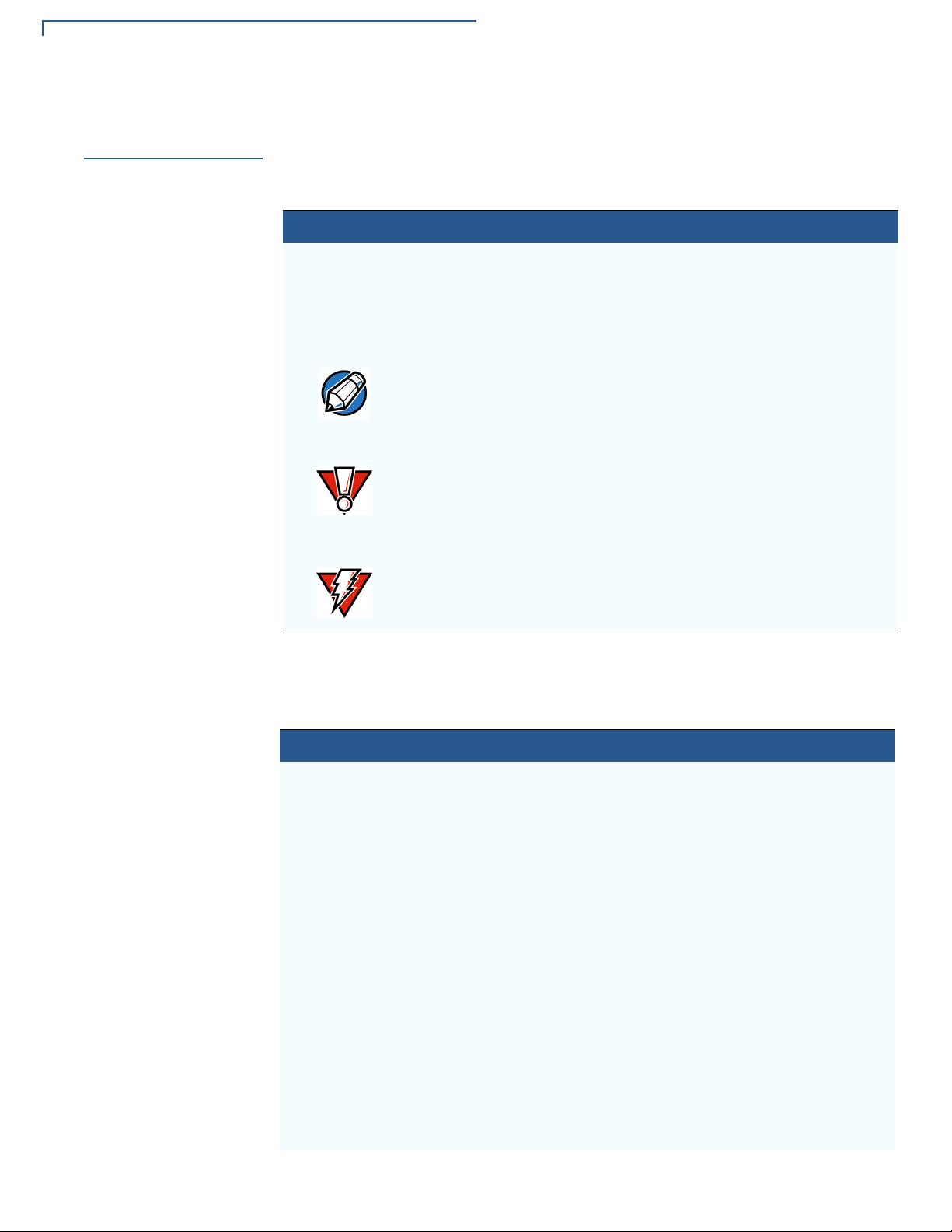
Guide Conventions
Guide
Conventions
Various conventions are used to help you quickly identify special formatting.
Table 1 describes these conventions and provides examples of their use.
Table 1 Document Conventions
Convention Meaning Example
Blue Text in blue indicates terms that
are cross references.
Italics Italic typeface indicates book
titles or emphasis.
The pencil icon is used to
NOTE
CAUTION
WARNING
highlight important information.
The caution symbol indicates
hardware or software failure, or
loss of data.
The lighting symbol is used as a
warning when bodily injury might
occur.
See Guide Conventions.
You must not use this unit
underwater.
RS232-type devices do not work
x
on the V
port.
The unit is not waterproof or
dustproof, and is intended for
indoor use only.
Due to risk of shock do not use
the terminal near water.
810CTLS communication
Acronym Definitions
Various acronyms are used in place of the full definition. Table 2 presents
acronyms and their definitions.
Table 2 Acronym Definitions
Acronym Definitions
AES Advanced Encryption Standard Algorithm
API Application Programming Interface
ARM Advanced RISC Machines
CAPK Certification Authority Public Key as in the EMV standard
CBC Cipher Block Chaining mode, as defined in ANSI X3.106
COG Chip on Glass
COGS Cost of Goods Sold
CTS Clear to Send
DEA/DES Data Encryption Algorithm/Standard, as defined in ANSI X3.92
DUKPT Derived Unique Key Per Transaction Method as defined in the
VISA’s POS Equipment Requirement: PIN processing and Data
Authentication, International Version 1.0, August 1988
ECB Electronic Code Book mode, as defined in ANSI X3.106
ECR Electronic Cash Register
EMV Joint Europay, MasterCard and Visa Standard
ERS Engineering Requirements Specification
4 V
X
810 INSTALLATION GUIDE
Page 7

Guide Conventions
Table 2 Acronym Definitions (continued)
Acronym Definitions
GID Group Identifier - Concept inherited from Verix terminals file
system
HDLC High-level Data Link Control
ICC Integrated Chip Card (Smart Card)
LCD Liquid Crystal Display
MAC Message Authentication Code, as defined in ANSI X9.19
MMU Memory Management Unit
MSAM Multiple Secure Access Module
MSR Magnetic Stripe Reader
OS Operating System
PED PIN Entry Device
PIN Personal Identification Number
POS Point-of-Sale
PRD Product Requirement Document
PSCR Primary Smart Card Reader
RFID Radio Frequency Identification
RTS Ready to Send
SOC System on Chip
SAM Secure Access Module
SC Smart Card (Integrated Chip Card)
SD Secure Digital
SDK Software Development Kit
SL3 Security Level 3 and 4
SR Ship Release
SRAM Static Random Access Memory
STN Super Twisted Nematic
UI User Interface
USB Universal Serial Bus
VSS VeriShield Security Scripts
PREFACE
X
810 INSTALLATION GUIDE 5
V
Page 8

PREFACE
Guide Conventions
6 V
X
810 INSTALLATION GUIDE
Page 9

Vx810 Overview
7
CHAPTER 1
This chapter provides a brief description of the Vx810. The Vx810 is a customerfacing premium PIN pad brought about by VeriFone’s innovative Purpose Inspired
Design program which focuses on real-world usage.
Apart from its sleek, compact, and functional design, the V
track, high coercivity magnetic stripe reader (MSR) and a Smart Card reader , both
built and proven to perform consistently, even under the heaviest volumes. It also
has an SD card slot for supporting application download via SD memory card. The
SD card slot also serves as an SDIO expansion port to simplify upgrades to
contactless or other emerging technologies – without replacing the PIN pad.
x
The V
(including serial, USB, or optional Ethernet) so you can connect to almost any
device or ECR. Plus, the V
printer and modem to create a fully-loaded payment solution with a hand-over PIN
pad – all in one single device.
810 also offers an array of connectivity options all from a single port
x
810 gives you the option to add a base unit with a
3
.
B
ON
I
S
I
x
810 features a triple-
V
E
R
x
Figure 1 The V
NOTE
Ve riFone ships variant s of the Vx810 for different markets. Your device may have
a different configuration. For example, the V
may or may not have an MSR; it may have none or 3 SAMs; flash ROM size may
be from 4MB, to 8MB or 16MB; and SRAM size may be from 2MB to 4MB.
However, the basic processes described in this guide remain the same,
regardless of configuration.
810
x
810 may or may not have a PSCR; it
Page 10

VX810 OVERVIEW
8
Features and Benefits
Features and
Benefits
E
V
O
C
Acclaimed Vx Solutions Reliability and Security Guarantees Extra
Protection
• Runs on V erix-based platform, proven in millions of VeriFone V
installed worldwide.
• Has exceptionally reliable magnetic stripe and smart card readers to
reduce read errors.
• Is PCI-PED approved for secure, reliable PIN entry on debit transactions.
• Has received EMV Level 1 and 2 Type Approval for smart card
transactions.
• Provides end-to-end SSL security and supports the latest security options
– including 3DES encryption, and Master/Session and DUKPT (Derived
Unique Key Per Transaction) key management.
• Relies on V eriShield file authentication to help stop fraud and misuse, such
as downloading rogue files or physical tampering.
• Hardware and software application separation minimizes or eliminates the
F
need to re-certify existing payment applications every time an application
is added or modified.
ONE
NT
IA
L
x
RI
DE
Flexibility and Future-Proofing Can Put You Years Ahead to
FI
Safeguard Your Investment
N
• Includes an SD card slot for supporting application download via SD
memory card. The SD card slot also serves as an SDIO expansion port to
simplify upgrades to contactless (the V
technologies – without replacing the PIN pad.
ON
• Provides for a wide range of connectivity via a single connector – including
RS-232, USB, and optional Ethernet – to accomodate nearly any ECR and
fit most merchant needs.
V
E
I
S
I
R
• Offers the option of adding a base unit (the V
x
the V
thermal printer, modem, Ethernet, USB, and serial ports.
810 PIN pad into an all-in-one countertop payment solution with
3
.
x
810 CTLS) or other emerging
B
x
810 DUET) that transforms
Solutions
• Extensive memory (6 MB standard, 12 MB or 20 MB optional) to support
multiple applications, including revenue-producing value-added solutions.
• Uses a 200 MHz, 32-bit, ARM 9 processor for trouble-free multitasking.
12 V
X
810 REFERENCE GUIDE
Page 11

Setup
9
CHAPTER 3
This chapter describes the setup procedure for Vx810, in the following sections:
• Selecting Location
• Unpacking the Shipping Carton
V
Selecting
Location
O
C
Ease of Use
• Examining the V
• Installing/Replacing MSAM Cards
• Options
• Cable Connections
• Power Supply
• Using the Primary Smart Card Reader
x
810 Features
F
L
IA
ONE
NT
RI
• Using the Magnetic Stripe Card Reader
E
• Using the SDIO Contactless Module
DE
FI
Use the following guidelines to select a location for the Vx810.
N
2
.
B
• Select a location convenient for both merchant and cardholder.
ON
• Select a flat support surface, such as a countertop or table.
• Select a location near a power outlet and the other VFI device, ECR, or
computer connected to the V
across a walkway.
R
V
E
I
S
I
x
810. For safety, do not string cables or cords
Environmental
Factors
CAUTION
• Do not use the device where there is high heat, dust, humidity, moisture, or
caustic chemicals or oils.
• Keep the device away from direct sunlight and anything that radiates heat,
such as a stove or a motor.
• Do not use the device outdoors.
The device is not waterproof or dustproof, and is intended for indoor use only.
Any damage to the device from exposure to rain or dust can void warranty.
VX810 REFERENCE GUIDE 21
Page 12

SETUP
Unpack Shipping Carton
Electrical
Considerations
WARNING
Unpack
Shipping Carton
• Avoid using this product during electrical storms.
• Avoid locations near electrical appliances or other devices that cause
excessive voltage fluctuations or emit electrical noise (for example, air
conditioners, electric motors, neon signs, high-frequency or magnetic security
devices, or computer equipment).
• Do not use the V
Due to risk of shock or damage, do not use the Vx810 near water, including a
bathtub, wash bowl, kitchen sink or laundry tub, in a wet basement, or near a
swimming pool.
Open the shipping carton and carefully inspect its contents for possible tampering
or shipping damage. The V
it to cease to function or to operate in an unsecured manner.
1 Remove and inspect the contents of the shipping carton, since the V
ships in multiple configurations, the carton may include any or all of the
following:
x
• V
810CTLS
x
810 near water or in moist conditions.
x
810 is a secure product and any tampering can cause
x
810
WARNING
• Data cable
• Power pack
• Power cord
• ECR cable
• Privacy shield
2 Remove all plastic wrapping from the terminal and components.
3 Remove the clear protective film from the display.
4 Save the shipping carton and packing material for future repacking or moving
of the device.
Do not use a unit that has been tampered with or damaged.
x
The V
appears damaged, please notify the shipping company and your VeriFone
service provider immediately.
810 comes equipped with tamper-evident labels. If a label or component
10 V
X
810 INSTALLATION GUIDE
Page 13

SETUP
Examine Vx810 Features
Examine
Vx810 Features
Before you continue with the installation process, familiarize yourself with the
x
810 features:
V
FUNCTION KEYS
DISPLAY
MAGNETIC CARD
READER
ALPHA
COLOR-CODED
FUNCTION KEYS
(OPTIONAL)
Figure 2 V
x
The V
810 includes the following features:
x
810 Features
ATM SYLE KEYS
TELCO KEYPAD
SMART CARD
READER
(OPTIONAL)
• A display.
• Three types of keys:
• Keypad matrix for four ATM-style keys and four Function keys.
• Alpha key for entering text.
• Three color-coded function keys below the keypad (CANCEL [RED],
BACKSPACE [YELLOW], ENTER [GREEN]).
• A magnetic card reader, built into the top side. An icon shows the proper
swipe direction, with the stripe facing down and towards the keypad.
• A smart card reader, built into the unit’s front side. An icon indicates the
proper card position and insertion direction. (Optional)
• A SAM (Security Access Module) compartment, built into the back side
x
of the unit. The V
support multiple stored-value card programs or other merchant card
requirements. (Optional)
810 contains multiple-SAM (MSAM) cardholders to
VX810 INSTALLATION GUIDE 11
Page 14

SETUP
Install/Replace MSAM Cards
Install/Replace
MSAM Cards
CAUTION
To change or install
MSAMs
You may need to install one or more multiple security access module (MSAM)
cards or replace the old cards.
Observe standard precautions in handling electrostatically sensitive devices.
Electrostatic discharges can damage the equipment. VeriFone recommends
using a grounded anti-static wrist strap.
1 Remove the data cable from the back of the unit.
2 Place the V
scratches.
x
810 facedown on a soft, clean surface to protect the lens from
3 Loosen the retaining screw. The restraining screw is captive, which means
that it cannot be fully removed from the slot.
NOTE
Figure 3 MSAM Compartment Door and Locking Screw
4 Lift open the compartment door. The MSAM cardholders are now accessible.
Each cardholder consists of a slot inboard of a numbered tray.
Figure 4 Opening MSAM Compartment Door
Before inserting the MSAM card, position it as shown in Figure 5, with the card’s
gold contacts facing away from you, toward the unit. The cardholder slot in the
x
V
810 has a set of contacts. The MSAM card has a notch on one corner to
ensure that it fits into the connector base in only one way; the V
matching notch cast into the backside of the MSAM compartment door to ensure
the MSAM card is positioned correctly when the cover is closed.
x
810 has a
12 V
X
810 INSTALLATION GUIDE
Page 15

Install/Replace MSAM Cards
5 Install the MSAM card by aligning the card to match the embossed number
and carefully sliding it into the slots until fully inserted.
Figure 5 MSAM Insertion
6 Close the MSAM compartment door and tighten the locking screw.
SETUP
Figure 6 Closed MSAM Compartment
X
810 INSTALLATION GUIDE 13
V
Page 16

SETUP
13-1
Options
Options
SDIO Contactless
Module
V
VeriFone ships variants of the Vx810 for different markets. Your device may have
a different configuration. Additionally, these variants can be ordered with different
options.
This SD card slot on the Vx810 also serves as an SDIO expansion port for
installing an optional SDIO contactless module used for contactless smart card
transactions.
Installing the SDIO Contactless Module
To install the SDIO contactless module:
1 Place the device facedown on a soft, clean surface to protect the lens from
scratches.
2 Insert the SD card of the RFID canopy into the SD card slot of the V
L
x
810.
IA
O N E
F
N T
R I
E
Figure 7 Sliding the RFID Canopy
F I
3 Install the metal plate onto the back of the RFID canopy and V
N
locking screws to lock the metal plate into position.
D E
x
810. Use the
C
O
NOTE
2
.
B
O N
I
S
I
V
E
Figure 8 Installing the Metal Plate
Figure 9 Installed SDIO Contactless Module
Proper care to ensure that the contactless module is working properly includes:
• Preventing the module from coming into contact with other metallic surfaces
while in use.
R
26 V
X
810 REFERENCE GUIDE
• Turning off the module when not in use.
Page 17

SETUP
Privacy Shield
Privacy Shield
Cable
Connections
This figure shows an example of a Vx810 with the privacy shield installed.
Figure 10 Installed Priva
The Vx810 has six general cabling scenarios, depending on what the Vx810
connects to:
cy Shield
1 Connection to another VeriFone Terminal
CAUTION
2 RS232 Connection using an External Power Brick
3 Direct USB Connection
4 USB–Download Support using an External Power Brick
5 Terminal using a PoweredUSB connection
6 Ethernet Connection with External Power Brick
Using an incorrectly rated power supply can damage the unit or cause it not to
work properly. Use only a power pack with VPN CPS11212-3A-(R) (see
Specifications for detailed power supply specifications).
14 V
X
810 INSTALLATION GUIDE
Page 18

SETUP
Cable Connections
Connection to
another VeriFone
Termi nal
RS232 Connection
using an External
Power Brick
The Vx810 connects to a VeriFone terminal via a straight cable. There is a
minimum power requirement for the V
where the terminal is only able to provide a 7 V DC output to power the V
x
810, currently specified as 3.5W. In cases
x
810, the
terminal must be able to source at least 0.5 A of current. Otherwise, proper
functioning of the V
Figure 11 V
x
810 is not guaranteed.
x
810 Connected to Another VeriFone Terminal
A special dongle cable is used, where one end of the cable plugs into the Vx810
while the other end terminates in a DB-9 connector housing. On the housing, a
DC jack is provided to connect to an external power brick. This is a generic cable
for all RS232-based hosts.
Figure 12 V
Brick
x
810 with an RS232 Connection Using an External Power
X
810 INSTALLATION GUIDE 15
V
Page 19

SETUP
Cable Connections
Direct USB
Connection
USB–Download
Support using an
External Power
Brick
Similarly, a dongle cable is required in standard USB environments. For this cable
option, the host end has a molded housing which exposes the standard USB plug.
Figure 13 Direct USB Connection
This cable option comes with a junction box that provides a mini-style Type B USB
socket for connecting to the USB-based host and a DC jack for external power
connection.
In addition, a Type A USB socket is provided on the junction box to support
application download via a USB thumb drive.
16 V
Terminal using a
PoweredUSB
connection
X
810 INSTALLATION GUIDE
x
Figure 14 V
810 Connected to a USB with Download Support
For a USB-based host with PoweredUSB feature, a straight cable is all that is
required. The V
x
810 supports the 12 V DC option.
Figure 15 PoweredUSB Connection
Page 20

SETUP
Power Supply
Ethernet
Connection with
External Power
Brick
Power Supply
The cable required junction box that provides a standard RJ-45 LAN socket and a
DC jack. However, since most hosts do not support peer-to-peer LAN connection
to a PIN pad, an additional RJ-45 socket is provided on the junction box to allow a
direct connection between V
Figure 16 Ethernet Connection with Exte
x
810 and the host.
rnal Power Brick
Not all Vx810 configurations and device contexts require the use of a power
x
supply – VeriFone ships power supplies with the V
If you have changed the context in which the V
810 as required.
x
810 is used or have questions
about which power supply should be used, contact your VeriFone representative.
CAUTION
WARNING
NOTE
Using an incorrectly rated power supply can damage the unit or cause it not to
work properly. Use only a power pack with VPN CPS11212-3A-(R) (see
Specifications for detailed power supply specifications).
Before connecting a power supply, disconnect the power pack cord from the
power outlet.
Connect and route all cables between the V
x
810, ECR, and PC before plugging
the power pack cord into a wall outlet or surge protector.
Do not plug the power pack into an outdoor outlet or operate the Vx810 outdoors.
Also, disconnecting power during a transaction can cause transaction data files
not yet stored in memory to be lost.
To protect against possible damage caused by lightning strikes and electrical
surges, VeriFone recommends installing a power surge protector.
When the V
x
810 has power and an application is loaded, the application starts
after the initial VeriFone copyright screen and displays a unique copyright screen.
If no application is loaded,
DOWNLOAD NEEDED appears on the display after the
initial VeriFone copyright screen.
X
810 INSTALLATION GUIDE 17
V
Page 21

SETUP
Smart Card Reader Use
Smart Card
Reader Use
To Conduct a Smart
Card Transaction
The smart card transaction procedure can vary depending on the application.
Verify the proper procedure with your application provider before performing a
smart card transaction.
1 Position the smart card with the gold contacts facing upward (see Figure 14).
2 Insert it into the smart card reader slot in a smooth, continuous motion until it
seats firmly.
3 Remove the card when the display indicates the transaction is completed.
Figure 17 Smart Card Reader Use
CAUTION
Leave the smart card in the card reader until the transaction is completed.
Premature removal can void the transaction.
18 V
X
810 INSTALLATION GUIDE
Page 22

SETUP
Magnetic Card Reader Use
Magnetic Card
Reader Use
To Conduct a Credit/
Debit Card
Transaction
The Vx810 has a magnetic card reader that uses a triple track stripe reader. This
gives the unit greater reliability over a wide range of swipe speeds and operating
environments.
1 Position a magnetic card with the stripe facing the keypad.
2 Swipe it through the magnetic card reader.
Figure 18 Magnetic Card Reader Use
X
810 INSTALLATION GUIDE 19
V
Page 23

SETUP
20
Using the SDIO Contactless Module
Using the SDIO
Contactless
Module
E
To conduct a contactless smart card transaction:
1 Gently tap the card onto or hold the card (up to 4 cm.) against the surface of
the RFID canopy.
2 An activated LED visual on the RFID canopy accompanied by a short beeping
sound indicates a successful transaction.
L
Figure 19 Contactless Smart Card Reader Use
F
O N E
N T
R I
D E
IA
C
V
O
N
F I
R
E
V
2
.
B
O N
I
S
I
32 V
X
810 REFERENCE GUIDE
Page 24

Specifications
3
21
Product
Specifications
CHAPTER 7
This chapter describes the technical specifications for the Vx810 device.
Model
Processor
Flash ROM
SRAM
Operating System
V
Display
O
C
Magnetic Card
Reader
Primary Smart Card
Reader
SAM Card Reader
Vx810
L
200 MHz Samsung S3C2410 ARM920 32-bit microprocessor
4MB installed (expandable to 8MB or 16MB)
F
2MB installed (expandable to 4MB)
NT
RI
ONE
E
Verix V platform. Built specifically to provide true and secure multi-application
capability, as well as dynamic memory allocation and file authentication.
N
128 x 128 pixel (2.75-inch) graphical LCD with high-contrast white backlighting.
Supports 16 lines x 21 characters with standard font set.
(Optional) Triple-track. High coercivity. Bi-directional. Compliant to ISO 7810 and
ISO 7811.
(Optional) Support for ISO 7816, 1.8V, 3V, 5V or synchronous and asynchronous
cards. EMV Level 1 and Level 2 Type approved.
(Optional) 1-3 Security Access Modules.
FI
DE
V
E
R
I
S
I
IA
ON
B
.
2
SD Card Reader
SDIO Contactless
Module
Support for standard SD memory card.
(Optional) Wireless Dynamics SDiD 1050 RFID Canopy with RFID SD Card.
• Reading range: 0 to 4 cm.
• Support for ISO 14443 A&B, Mifare, NFC, and FeliCa card types.
• Support for standard payment applications: PayPass MChip and MSD,
Visa qVSDC and MSD, Express Pay, Discover Contactless, and NETS
CEPAS.
VX810 REFERENCE GUIDE 129
Page 25

SPECIFICATIONS
22
Environmental, Regulatory and Performance Specifications
Input Device
Peripheral Ports
Supported Memory
Media
V
Security
O
C
Audio Output
Physical
Rubber keys:
• 4 ATM-style function keys (F1 to F4)
• 4 programmable function keys (PF1 to PF4)
• 1 ALPHA key
• Main keypad (0 to 9, *, and #)
• 3 command keys (CANCEL, CLEAR, and ENTER)
Single multi-connector, which supports power, RS-232, USB Client, USB Host,
Ethernet, and power over Ethernet. SDIO interface supports optional expansion
module for contactless payments or SD memory card.
SD Memory Card
• Sandisk SD: SDSDB-512 / SDSDB-256 / SDSDB-128
USB Flash Drive
IA
L
ONE
E
• Sandisk Cruzer Mini: SDCZ2-256-A10
• Memorex Thumbdrive: 32507725
RI
• Kingston DataTraveler: KUSBDTI256
• PNY USB Flash: PFD256U20RF
FI
• Lexar USB Pro: JD256-80-231
F
DE
NT
N
3DES encryption, Master / Session and DUKPT key management. PCI-PED
B
.
2
approved. VeriShield file authentication.
Monophonic
ON
I
V
S
I
Standard: Length: 150 mm (5.9 in.). Width: 85 mm (3.3 in.). Height: 32 mm (1.2
in.). Weight: terminal, 270 g (0.59 lbs.); full shipping, 850 g (1.87 lbs.).
With contactless module: Length: XXX mm (XXX in.). Width: 85 mm (3.3 in.).
Height: XXX mm (XXX in.). Weight: terminal, XXX g (XXX lbs.); full shipping, XXX
g (XXX lbs.).
E
R
Environmental,
Regulatory and
Performance
Specifications
130 V
X
810 REFERENCE GUIDE
Voltag e
Input: AC 100-240V, 50-60Hz. Output: DC 5-12V. 2.5-W maximum consumption.
The Vx810 meets all the necessary environmental, regulatory and performance
standards for its intended use and expected market. VeriFone recognizes its
responsibility to minimize the environmental impacts of its operations and
products.
x
The V
operation in retail environments where the product is handed over the counter to
the consumer for payment transactions, PIN verification, etc.
810 is classified as a “portable general purpose” device. It is designed for
Page 26

SPECIFICATIONS
22-1
Environmental, Regulatory and Performance Specifications
This device is not intended for outdoor use and is certified for indoor use only.
Temperature and
Humidity
Compliance
Certifications
V
O
C
Operating Temperature and Humidity
• Temperature: 0
• Humidity: 5% to 90% RH, non-condensing
Storage Temperature and Humidity
• Temperature: -40
• Humidity: 15% to 95% RH, non-condensing
Emission Standards
This device is compliant to the following emission standards for information
technology equipment: Radiated and Conducted Emissions (EN 55022:2006 /
CISPR22).
o
C to +40oC (+32oF to +104oF)
o
C to +70oC (-40oF to +158oF)
L
IA
Immunity Standards
F
This device is compliant to the following immunity standards for information
technology equipment: Immunity Limits & Methods of Measurement (EN
RI
55024:1998+A1:2001+A2:2003), Electrostatic Discharge (ESD) Immunity (IEC
E
61000-4-2:2001), Radiated Immunity (IEC 61000-4-3:2006), Electrical Fast
Transients (EFT) Burst Immunity (IEC 61000-4-4:2004), Surge (IEC 61000-45:2005), Conducted Immunity (IEC 61000-4-6:2004+A1:2004+A2:2006),
N
Magnetic Field Susceptibility (IEC 61000-4-8:2001), Voltage Dips (IEC 61000-411:2004), Harmonic Current Emissions (EN 61000-3-2:2006), Flicker (EN 610003-3:1995+A1:2001+A2:2005).
FI
DE
ONE
NT
B
.
2
S
ON
I
X
810 REFERENCE GUIDE 131
V
Safety Standards
This device is compliant to the following immunity standards for information
technology equipment: UL 60950-1:2003 (1st Ed.) and EN 60950-1:2001+
A11:2004.
Other Standards
This device is compliant to the following PTT certifications: CFR 47 Part 68 and
CS-03.
E
R
I
V
Page 27

Maintenance and Cleaning
The Vx810CTLS has no user-serviceable parts.
CHAPTER 4
Clean the
PIN Pad
CAUTION
Card Readers
To clean the unit, use a clean cloth slightly dampened with water and a drop or
two of mild soap. For stubborn stains, use alcohol or an alcohol-based cleaner.
For best results, use a Verifone Cleaning Kit (refer to the Accessories and
Documentation section).
Never use thinner, trichloroethylene, or ketone-based solvents – they can
deteriorate plastic or rubber parts.
Do not spray cleaners or other solutions directly onto the keypad or display.
Do not attempt to clean the card readers. Doing so can void any warranty. For
card reader service, contact your VeriFone distributor or service provider.
VX810 INSTALLATION GUIDE 23
Page 28

MAINTENANCE AND CLEANING
Card Readers
24 V
X
810 INSTALLATION GUIDE
Page 29

Service and Support
For Vx810CTLS problems, contact your local VeriFone representative or service
provider.
For V
• USA – VeriFone Service and Support Group, 1-800-834-4366,
Monday - Friday, 8 A.M. - 8 P.M., eastern time.
• International – Contact your VeriFone representative.
x
810CTLS product service and repair information:
CHAPTER 5
Service Returns
NOTE
Before returning the Vx810 to VeriFone, you must obtain a Merchandise Return
Authorization (MRA) number. The following procedure describes how to return
x
one or more V
International customers, please contact your local VeriFone representative for
assistance with your service, return, or replacement.
810 for repair or replacement (U.S. customers only).
1 Gather the following information from the printed labels (see Figure 16) on the
x
bottom of each V
810 to be returned:
• Product ID, including the model and part number. For example,
“m108-xxx-xx” and “PTID xxxxxxxx.”
• Serial number (S/N xxx-xxx-xxx).
2 Within the United States, call VeriFone toll-free at 1-800-834-4366.
3 Select the MRA option from the automated message. The MRA department is
open Monday–Friday, 8 A.M.–8 P.M., eastern time.
4 Give the MRA representative the information gathered in Step 1.
If the list of serial numbers is long, you can fax the list, along with the
information gathered in Step 1, to the MRA department at 1-727-953-4172
(U.S.).
• Please address the fax clearly to the attention of the “VeriFone MRA
Dept.”
• Include a telephone number where you can be reached and your fax
number.
VX810 INSTALLATION GUIDE 25
Page 30

SERVICE AND SUPPORT
Service Returns
• You will be issued MRA number(s) and the fax will be returned to you.
NOTE
One MRA number must be issued for each Vx810 you return to VeriFone, even if
you are returning several of the same model.
5 Describe the problem(s) and provide the shipping address where the repaired
or replacement unit must be returned.
6 Keep a record of the following items:
• Assigned MRA number(s).
• VeriFone serial number assigned to the V
service or repair (serial numbers are located on the bottom of the unit (see
Figure 16).
x
810 you are returning for
• Shipping documentation, such as air bill numbers used to trace the
shipment.
• Model(s) returned (model numbers are located on the VeriFone label on
the bottom of the V
x
810).
Figure 20 Informat
MODEL NUMBER
SERIAL NUMBER
ion Label on Unit Bottom
26 V
X
810 INSTALLATION GUIDE
Page 31

SERVICE AND SUPPORT
Accessories and Documentation
Accessories and
Documentation
Supplementary
Hardware
Data Cables
Power Supply
VeriFone produces accessories and documentation for the Vx810CTLS. When ordering,
please refer to the part number in the left column.
VeriFone Online Store at www.store.verifone.com
• USA – VeriFone Customer Development Center, 1-800-834-4366,
Monday - Friday, 7 A.M. - 8 P.M., eastern time
• International – Contact your VeriFone representative
08392-01-(R) Mounting adapter
08368-01-(R) Privacy shield
08361-XX-(R) Connects Vx810 to Vx510, Vx570 and, Vx610 terminals (Mod-
10)
08398-XX-(R) Connects V
Various others, depending on what they connect to. Contact your local
VeriFone representative or service provider to identify the best cable for your
needs.
Power packs are optional, except in certain instances (see Power Supply).
x
810 to ECR with USB Type A
Power Cord
Cleaning Kit
Documentation
CPS11212-3A-R DC power pack (universal)
07152-02-R
AC power cord (US)
07152-xx United States of America
Various others, by country: contact your local VeriFone representative or
service provider to identify the best power cord for your needs.
02746-01(-R) VeriFone Cleaning Kit
To learn more about Vx810, refer to the following set of documents:
x
V
810 Certification and Regulation Sheet
x
V
810 Quick Installation Guide
x
V
810 Reference Guide
x
V
810 Privacy Shield Quick Installation Guide
x
V
810 Stand Adapter Quick Installation Guide
VPN 24960
VPN 24961
VPN 24964
VPN 24965
VPN 24966
X
810 INSTALLATION GUIDE 27
V
Page 32

SERVICE AND SUPPORT
Accessories and Documentation
28 V
X
810 INSTALLATION GUIDE
Page 33

CHAPTER 6
Troubleshooting
NOTE
CAUTION
Guidelines
This chapter lists typical examples of malfunctions that you may encounter while
operating your V
The troubleshooting guidelines provided in the following section are included to
assist successful installation and configuration of the V
problems operating your V
the problem persists even after performing the outlined guidelines or if the
problem is not described, contact your local VeriFone representative for
assistance.
The Vx810 comes equipped with tamper-evident labels. The Vx810 contains no
user-serviceable parts. Do not, under any circumstance, attempt to disassemble
the unit. Perform only those adjustments or repairs specified in this guide. For all
other services, contact your local VeriFone service provider. Service conducted
by parties other than authorized VeriFone representatives may void any warranty.
Not all units require use of a power supply.
x
810 and the steps that you can take to resolve them.
x
810. If you are having
x
810, please read these troubleshooting examples. If
Blank Display
Keypad Does
Not Respond
Using an incorrectly rated power supply may damage the unit or cause it not to
work properly. Before troubleshooting, ensure that the power supply used to
power the unit matches the requirements specified on the back of the unit (see
Specifications for detailed power supply specifications). If not, obtain the
appropriately rated power supply before continuing with troubleshooting.
When the Vx810 display does not show correct or clearly readable information:
• Check all power and cable connections.
• If the problem persists, contact your local VeriFone service provider.
If the keypad does not respond properly:
• Check the display. If it displays the wrong character or nothing at all when you
press a key, follow the steps outlined in Transactions Fail To Process.
• If pressing a function key does not perform the expected action, refer to the
user documentation for that application to ensure you are entering data
correctly.
• If the problem persists, contact your local VeriFone representative.
VX810 INSTALLATION GUIDE 29
Page 34

TROUBLESHOOTING GUIDELINES
Transactions Fail To Process
Transactions
Fail To Process
There are several possible reasons why the unit may not be processing
transactions. Use the following steps to troubleshoot failures.
Check Magnetic Card Reader
• Perform a test transaction using one or more different magnetic stripe cards to
ensure the problem is not a defective card.
• Ensure that you are swiping cards properly (see Magnetic Card Reader Use).
• Process a transaction manually using the keypad instead of the card reader. If
the manual transaction works, the problem may be a defective card reader.
• If the problem persists, contact your local VeriFone representative.
Check Smart Card Reader
• Perform a test transaction using several different smart cards to ensure the
problem is not a defective card.
• Ensure that the card is inserted correctly (see Smart Card Reader Use).
• Ensure the MSAM cards are properly inserted in the slots and are properly
secured (see Install/Replace MSAM Cards).
• If the problem persists, contact your local VeriFone representative.
30 V
X
810 INSTALLATION GUIDE
Page 35

x
V
810 CTLS
Certifications and Regulations
FCC Compliance
The following product has been tested and certified as compliant with the regulations and guidelines set forth in Part 15 of FCC Rules:
Manufacturer: VeriFone, Inc.
Model:
Vx810 CTLS
Part 15 of FCC Rules
The equipment has been tested and found to co mpl y with th e lim it s for Cl ass B d igit al device , purs uant to Part 15 of th e FCC R ules.
This device complies with Part 15 of the FCC Rules. Operation is subject to the following conditions:
• This device must not cause harmful interference; and
• This device must accept any interference received including interference that may caused undesired operation.
This equipment generates and uses radio frequency energy, and if not installed and used in accordance with the instructions, may
cause harmful interference to radio communications. However, there is no guarantee that interference will not occur in a particular
installation.
In the unlikely event that there is interference to ra dio or tele vision recep tion (whi ch can be deter mined by turn ing the eq uipment off
and on), the user is encouraged to try to correct the interference by one or more of the following measures:
• Reorient or relocate the receiving antenna.
• Increase the separation between the equipment and receiver.
• Connect the equipment into an outlet on a circuit different from that to which the receiver is connected.
• Consult with the dealer or ask an experienced radio/TV technician for help.
Any changes or modifications to this equipment not expressly approved by VeriFone could void the user’s authority to operate this
equipment.
Warning
The IC Warning Message operation is subject to the following conditions:
• This device may not cause interference, and
• This device must accept any interference that may cause undesired operation of the device.
To comply with the FCC RF exposure compliance requirements, make sure to use only the antenna that is included with the d evice.
This device and its antenna must not b e in the same lo cation or operating in the sam e area in conjun ction with any o ther ant enna o r
transmitter.
RF Exposure
This device was verified for RF exposure. To comply with Council Recommendation 1999/519/EC, IC RSS-102, and FCC RF
exposure requirements, a minimum separation distance of 20 cm must be maintained between the user's body and the device,
including the antenna. Any metallic components should be far from this device. Conditions that do not meet these requirements
may not comply with Council Recommendation 1999/519/EC, IC RSS-102 and FCC RF exposure requirements and should be
avoided.
Other Information
This equipment may be operated in AUT, BUL, HRV, CZE, CYP, DNK, EST , FIN, F, D, GRC, HNG, ISL, IRL, I , LIE, LUX, HOL, POL
POR, ROU, SVN, SVK, E, S, SUI, G.
The use of this equipment requir es a licence in BEL, LVA, LTU, NOR.
Page 36

VeriFone, Inc.
2099 Gateway Place, Suite 600
San Jose, CA, 95110 USA
Tel: (800) VeriFone (837-4366)
www.verifone.com
Vx810 CTLS
Installation Guide
VeriFone Part Number 24963, Revision A
 Loading...