

Page 1
VTTEST
1
K
R
C
E
R
O
U
A
N
A
C
ÉR
E
T
T
CABLE TRAC
KABELTESTE
TESTEUR DE
DETECTOR D
KABELFINDE
1N
ER WITH TONE GE
MET TOONGENER
ÂBLE AVEC GÉN
CABLES CON GEN
MIT TONGENERA
ERATOR
TOR
ATEUR DE TONALI
RADOR DE TONOS
OR
USER MANUAL
GEBRUIKERSH
MODE D'EMPL
MANUAL DEL
BEDIENUNGS
ANDLEIDING
I
SUARIO
NLEITUNG
3
8
14
20
26
Page 2
VTTEST11N
V. 01 – 15/01/2013 2 ©Velleman nv
Page 3
/
t
n
n
o
r
i
u
o
o
ging
n
g
p
n
epag
m
n
k
s
t
m
s
r
o
o
r
e
e
h
T
A
m
o
;
e
a
v
n
n
c
e
e
o
r
k
m
a
©
o
a
a
o
s
o
a
a
y
u
h
v
i
b
m
n
e
g
g
1. Introduc
To all reside
Important e
returned to yo
the local env ir
If in doubt, c
Thank you for
before brin
transit, don't i
This cable trac
without dama
checking for o
2. Safety I
Refer to the V
es of this
• Keep this d
temperatur
• Protect this
operating t
V. 01 – 15/01
USER M
ion
ts of the European
vironmental infor
This
symbol on the device
sal of the device afte
disp
envi
onment. Do not disp
unso
rted municipal waste
alized company for r
spec
r distributor or to a l
nmental rules .
ntact your local w
choosing Velleman! P
this device into ser
stall or use it and co
ker is designed to ide
ing the insulation, an
ens / shorts.
structions
lleman® Service a
anual.
ing: Live, facility ele
War
shoc
s, burns, and even d
hand
or arms. If the cabl
circui
, the circuit breaker
the
ain breaker box befo
In thi
case, the cable trac
elect
ician.
Do n
t use the devic e in a
Not f
llowing instructions
or pe
sonal injury.
vice away from rain
s.
device from shocks a
e device.
2013 3
VTTES
11N
NUAL
Union
ation about this pr
or the package indic
r its lifecycle could h
se of the unit (or bat
it should be taken t
cycling. This device
ocal recycling service
ste disposal auth
lease read the manu
ice. If the device was
tact your dealer.
ntify and trace wires
d to test continuity al
d Quality Warrant
trical circuits can ca
ath if the circuit is to
tracker is used for t
r fuse must be remo
e tracking any electr
ing should be done
high voltage environ
ay cause damage to
nd moisture, dust a
nd abuse. Avoid brut
duct
tes that
rm the
teries) as
a
hould be
. Respect
rities.
l thoroughly
ed in
dama
nd cables
lowin
on the last
se serious
uched by
is type of
ed from
cal circuit.
y a licensed
ent.
the device
d extreme
force when
Velleman nv
Page 4
/
c
y
t
u
a
e
r
u
e
t
w
u
p
c
t
n
r
r
T
r
(
s
e
h
C
T
m
e
e
c
n
f
e
o
d
d
g
s
t
n
g
©
e
g
e
h
g
e
t
o
e
d
• Always swit
• Familiarise
using it.
• All modifica
Damage ca
by the warr
• Only use th
an unautho
• Damage ca
is not cover
responsibili
• Keep this m
3. Overvie
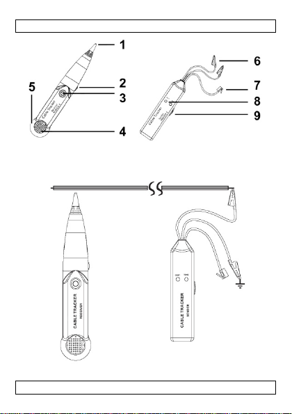
Refer to the ill
cable tracker
1 probe ti
2 volume
3 trace bu
4 speaker
5 3.5 mm
4. Operatio
Neve
powe
4.1 Cable
The tone gene
is interrupted
1. Set the to
2. Create a
end of th
3. Connect t
tested:
o If the
uninter
h off both the trans
ourself with the func
ions of the device ar
sed by user modifica
nty.
device for its intend
ised way will void th
sed by disregard of
d by the warranty a
y for any ensuing de
anual for future refer
strations on page 2
VTTES
(receiver)
ontrol
ton
headphones output
connect the test lea
ed line.
est
ator can be used to
test per wire pair).
enerator’s mode
ne
hort circuit between
cable.
e red and black con
ONT indicator [8] li
rupted.
11N
itter and the receive
tions of the device b
forbidden for safety
tions to the device is
ed purpose. Usin
warranty.
ertain guidelines in t
d the dealer will not
ects or problems.
nce.
f this manual.
tone
enerator (s
6 test leads
7 phone connec
8 LED indicators
9 mode switch
s with an active AC
etermine whether or
witch [9] to CONT.
he wires to be tested
ectors [6] to the wir
hts up, the two teste
r after use.
fore actually
reasons.
not covered
th
device in
is manual
accept
nder)
or
r DC-
not a cable
at the far
s to be
wires are
V. 01 – 15/01
2013 4
Velleman nv
Page 5

VTTEST11N
o If the CONT indicator [8] does not light, one or both of the
wires are broken, or the wrong wires were connected or short
circuited.
Caution: Make sure the pair of wires under test is not in contact
with any other electrified or earthed object, as this may cause an
incorrect result.
4.2 Cable Detection / Test
Use both the tone generator and the cable tracker to verify where a
cable is going, if it is interrupted or not and where the interruption is
located.
1. Set the tone generator's mode switch [9] to TONE.
The TONE indicator [8] starts flashing.
2. At one end of the cable / wires to be tested, connect the red clip
to any wire or one specific wire you want to test. Connect the
black clip to the ground wire or, if you cannot find it, one of the
other wires.
3. Use the volume control [2] on the side of the cable tracker to
control the volume.
4. Use the probe tip [1] of the cable tracker as follows:
o If you do not know where the cable is going or if there are
several similar cables, you can detect the correct one with the
probe. Hold the probe to the suspected wire and press the
trace button. The signal is the loudest at the correct wire.
o If you do know where the cable is going, the probe allows you
to verify immediately at the other end whether or not the
cable is interrupted. Hold the probe to the end of the wire and
press the trace button. If no signal is obtained, the test wire
is probably interrupted.
o Press and hold the trace button [3] and follow the cable to
where the signal stops: the signal wire is interrupted at that
point.
Remarks:
• The best test results are obtained when the black clip is connected
to a separate ground wire.
• The probe is very sensitive: as it gets nearer the signal wire, the
tone gets louder.
• Electric fields may interfere with the detection of the signal wire.
V. 01 – 15/01/2013 5 ©Velleman nv
Page 6

VTTEST11N
4.3 RJ12 Phone Connector Test
The tone generator can be used to determine the polarity of a phone
line, and the status of a working line.
1. Set the tone generator's mode switch [9] to OFF.
2. Insert the phone line connector [7] in the phone socket and
connect the red and black connectors [6] to the wires to be
connected. The CONT indicator [8] lights.
o Green means th e polarity is correct (black is "+" (tip) and red
is "–" (ring)).
o Red means the polarity is inversed (black is "–" (ring) and red
is "+" (tip)).
o If the LED does not light up, either the connections are not
established correctly or the socket is not connected.
3. To test the status of a telephone line, first connect the red
connector to the "–" (ring) side and the black connector to the
"+" (tip) side. The CONT indicator [8] lights.
o Green indicates a clear line.
o Flickering yellow means there is an incoming phone call (ring
signal).
Note: In this case, set the mode switch to CONT to terminate
the call on the line.
o If the LED does not light up, the line is busy.
4.4 Selecting the Tone
Select the tone you want to hear (single or dual tone) with the audio
signal switch at the inside of the tone generator.
1. Open the battery compartment and remove the battery.
2. Unscrew the screw in the battery compartment and the four
screws in the back cover.
3. Carefully remove the back cover and lift the PCB.
The audio signal switch is located at the left side of the PCB
(component side up, battery connectors at the bottom).
4. Set the switch in the desired position.
5. Replace the PCB carefully and put the cover back.
Caution: Make sure that no wires are crimped and that the
mode switch is in position. The indicator LEDs should fit easily
through the holes. Do not force.
6. Fix the back cover with the 5 screws.
7. Replace the battery and close the cover.
V. 01 – 15/01/2013 6 ©Velleman nv
Page 7
/
o
d
r
r
n
n
2
b
h
e
O
e
e
l
r
o
v
o
p
t
T
o
e
t
r
t
2
gh
e
n
s
9
5
3
9
0
0
2
2
6
©
a
g
r
d
O
h
t
u
5
×
×0 g
5. Batteries
1. On the to
2. Slide ope
3. Close the
4. On the ca
5. Replace t
6. Close the
Do n
explo
batte
local
(9 V, 6LF
t puncture batteries
e. Do not attempt to
ies (alkaline). Dispos
egulations. Keep bat
e generator, set the
the battery cover at
2). Respect the pola
battery cover.
le tracker, unscrew
e battery (9 V, 6LF2
battery cover and ti
6. Storage
• Remove th
long time.
• Store the d
temperatur
7. Technica
tone generato
working v
output wa
single audi
dual audio
cable tracker
working v
max. rece
maximum
dimensions
receiver
transmit
total weight
batteries from the d
ld batteries can begi
vice in a dry and du
.
Specifications
ltage DC
e form squa
o frequency ± 1
frequency ± 1
ltage DC
tion sensitivity > 3
output volume ± 1
er 145 × 35 ×
VTTES
238 x 43 ×
± 1
11N
r throw them in fire
recharge non-rechar
of batteries in acco
eries away from chil
mode switch [9] to
the back and replace
ity.
he battery cover at t
). Respect the polari
ten the screw.
vice if it will not be
to leak and damage
t-free place at room
V (battery not incl.)
re wave signals ± 3.
00 Hz
00 Hz - 1700 Hz
V (battery not incl.)
mV
0 dB
6 mm / 9.4" × 1.7"
5 mm / 5.7" × 1.4"
s they may
eable
dance with
ren.
FF.
the battery
e back.
y.
sed for a
the device.
Vpp
1.0"
1.0"
V. 01 – 15/01
2013 7
Velleman nv
Page 8
/
c
l
m
o
a
i
T
t
g
a
E
gez
m
y
d
v
a
n
n
e
w
a
t
o
T
e
f
w
s
T
o
a
o
c
o
e
l
a
j
s
e
g
e
t
m
a
©
e
o
s
m
ge
y
g
G
e
n
j
o
a
r
jd
o
Use this devi
cannot be he
resulting fro
For more inf
of this manu
The informat
prior notice.
© COPYRIGH
The copyrigh
worldwide ri
reproduced, tr
otherwise with
1. Inleiding
Aan alle in
Belangrijke
Dit s
als h
scha
even
afval
terechtkomen
naar een loka
milieuwetgevi
Hebt u vrage
betreffend d
Dank u voor u
toestel in gebr
transport, inst
Deze kabeltes
identificeren z
V. 01 – 15/01
e with original acc
d responsible in th
(incorrect) use o
concerning this pr
l, please visit our
on in this manual i
NOTICE
to this manual is
hts reserved. No p
nslated or reduced t
out the prior written
G
BRUIKERSH
etenen van de Eur
ilieu-informatie b
mbool op het toeste
et na zijn levenscyclu
e kan toebrengen a
tuele batterijen) niet
; het moet bi
oor recyclage. U mo
l recyclagepunt bren
.
, contacteer dan d
verwijdering.
aankoop! Lees dez
uik neemt. Werd het
lleer het dan niet en
er werd ontworpen o
nder beschadiging v
2013 8
VTTES
11N
essories only. Vell
event of damage
this device.
oduct and the late
ebsite www.velle
subject to chan
wned by Velleman
rt of this manual ma
any electronic medi
onsent of the copyri
ANDLEIDIN
pese Unie
treffende dit produ
of de verpakking ge
s wordt weggeworpe
n het milieu. Gooi dit
bi
een ge
pecialiseerd bedrijf
t dit toestel naar uw
en. Respecteer de pl
e plaatselijke auto
handleiding grondig
oestel beschadigd ti
raadpleeg uw dealer.
een kabel op te sp
n de isolatie, en de c
het gewone huish
man nv
r injury
t version
an.eu.
without
nv. All
be copied,
um or
ht holder.
ct
ft aan dat,
, dit toestel
toestel (en
udelijke
verdeler of
atselijke
iteiten
voor u het
ens het
ren en te
ontinuïteit
Velleman nv
Page 9
/
e
g
d
V
e
r
r
d
t
m
n
e
u
n
o
e
e
g
d
ghe
d
u
j
n
d
s
e
T
o
a
e
d
d
e
u
i
d
e
e
ge
g
d
o
©
s
n
c
g
,
e
c
n
g
h
c
n
u
e
e
b
j
a
m
ging
te testen om t
ontstaan.
2. Veili
hei
Raadpleeg de
achteraan dez
Waa
onde
bran
kabel
stroo
zeker
teste
door
Gebr
span
Het n
verw
• Bescherm d
temperatur
• Bescherm t
bediening.
• Schakel na
• Leer eerst
gebruiken.
• Om veili
Schade doo
niet onder
• Gebruik het
onoordeelk
• De garantie
richtli
nen i
verantwoor
rechtstreek
• Bewaar dez
zien of de leiding d
VTTES
sinstructies
elleman® service-
handleiding.
schuwing: Het aanr
stroom in gebouwen
wonden en zelfs fatal
ester gebruikt wordt
onderbreker of zek
ingkast alvorens een
. In dit geval, dient
en erkende elektrici
ik het toestel niet in
ing.
iet naleven van instr
ndingen veroorzaken
it toestel tegen regen
n.
en schokken. Verm
ebruik zowel de zen
e functies van het to
idsredenen mag u ge
r wijzigingen die de
e garantie.
toestel enkel waarvo
ndig gebruik vervalt
eldt niet voor scha
deze handleiding en
elijkheid afwijzen vo
verband mee houde
handleiding voor ve
11N
orloopt en geen kort
en kwaliteitsgara
ken van elektrische
kan leiden tot ernsti
e gevolgen hebben. I
voor dit type circuits
ring verwijderd word
er welk elektrisch cir
e kabeltest te worde
n.
eving onder
een om
cties kan materiële s
.
en vochtigheid, stof
d brute kracht tijde
er als de ontvanger
stel kennen voor u h
n wijzigingen aanbr
bruiker heeft aange
or het gemaakt is. Bi
de garantie.
e door het negeren v
uw dealer zal de
r defecten of proble
n.
rdere raadple
luiting is
tie
ircuits
e schokken,
ndien de
moet de
n uit de
uit te
uitgevoerd
oge
hade of
en extreme
s de
it.
t gaat
ngen.
racht valt
n bepaalde
en die hier
.
V. 01 – 15/01
2013 9
Velleman nv
Page 10
/
jv
a
o
e
k
-
n
e
n
s
o
e
e
e
gn
r
gn
l
n
e
e
o
l
T
0ing
n
o
e
e
d
m
c
t
r
r
g
t
e
e
©
d
e
c
a
o
e
n
j
p
b
o
g
g
3. Omschri
Raadpleeg de
meetsonde (
1 testpunt
2 volumer
3 zoekkno
4 luidspre
5 3.5 mm
4. Gebruik
Verbi
of lijn
4.1 Kabelt
Met de toonge
onderbroken i
1. Zet de m
2. Maak aan
de kabelk
3. Verbind d
kabelkern
o Als si
onderb
o Als si
kernen
aanges
Let op: zorg e
contact maken
stroom; dit ka
4.2 Kabeld
Gebruik zowel
komen waar e
zo ja: waar di
1. Zet de m
De signaa
VTTES
fbeeldingen op pagi
ntvanger)
eling
p
er
koptelefoonuitgang
d de meetsnoeren n
en (AC of DC).
st
erator kunt u bepal
(test per twee kabel
dusschakelaar van d
het andere eind van
rnen die u wil testen
rode en zwarte kle
n:
aalled CONT [8] opli
oken.
aalled CONT [8] nie
onderbroken, ofwel z
oten of kortgesloten.
rvoor dat de kabelke
met een geaard voo
een onjuist testresu
etectie / -test
de toon
enerator als
n kabel naartoe gaa
onderbreking zich b
dusschakelaar van d
led TONE [8] begint
11N
a 2 van deze handlei
toongenerator (z
6 testdraden
7 telefoonconne
8 signaalleds
9 modusschakel
oit met stroomvoere
n of een kabel al dan
kernen).
toongenerator [9]
e kabel een kortsluit
.
men [6] met de te t
ht, zijn de twee ker
oplicht, is ofwel één
n de verkeerde kern
i
nen die getest worde
werp of een voorwer
ltaat opleveren.
de meetsonde om te
, of een kabel onder
vindt.
toongenerator [9]
te knipperen.
ing.
nder)
tor
ar
nde kabels
niet
p CONT.
tussen
in
sten
en niet
of beide
en
een
n
onder
weten te
roken is en
p TONE.
V. 01 – 15/01
2013 1
Velleman nv
Page 11

VTTEST11N
2. Verbind aan het ene uiteinde van de te testen kabel de rode
klem met eender welke draadkern, of één specifieke kern die u
wil testen. Zet de zwarte klem op de aarding of, als deze niet
voorhanden is, op een van de andere draadkernen.
3. De geluidssterkte is regelbaar met de volumeregeling [2].
4. Gebruik het testpunt [1] als volgt:
o Als u niet weet waar een kabel naartoe gaat of er zijn
verschillende gelijke kabels, kunt u de juiste kabel vinden met
de sonde. Houd de sonde tegen de vermoedelijke kabel en
druk op de zoekknop. Het signaal klinkt het luidst ter hoogte
van de juiste kabel.
o Als u wel weet waar een kabel uitkomt, kunt u aan het andere
eind meteen testen of de kabel niet onderbroken is. Houd de
sonde tegen het uiteinde van de kabel en druk op de
zoekknop. Als er geen signaal is, is de geteste draadkern
waarschijnlijk ergens onderbroken.
o Volg de kabe l terwijl u de zoekknop [3] ingedrukt houdt tot
waar het signaal ophoudt; de draadkern is op dat punt
onderbroken.
Opmerkingen:
• U zult de beste testresultaten krijgen wanneer de zwarte klem
met een afzonderlijke aardekabel is verbonden.
• De sonde is zeer gevoelig: naarmate ze dichter bij de kabel komt,
wordt de toon luider.
• Elektrische velden kunnen de ontvangst van de signaalkabel
storen.
4.3 Telefoonaansluitingtest (RJ12)
De toongenerator kan worden gebruikt om de polariteit van een
telefoonlijn te bepalen, en de status van een actieve lijn.
1. Zet de modusschakelaar van de toongenerator [9] op OFF.
2. Steek de telefoonconnector [7] in de contactdoos van de
telefoon en verbind de rode en zwarte klemmen [6] met de
draden die moeten aangesloten worden. De signaalled CONT [8]
licht op.
o Groen betekent dat de polariteit juist is (zwart is "+" (tip) en
rood is "–" (ring)).
o Rood betekent dat de polariteit omgekeerd is (zwart is "–"
(ring) en rood is "+" (tip)).
V. 01 – 15/01/2013 11 ©Velleman nv
Page 12

/
t
a
o
gro
r
o
d
n
o
a
b
k
i
p
)
h
p
o
ge
d
b
n
g
o
r
n
g
b
T
2
e
o
n
g
v
t
e
e
r
n
jd
t
g
k
o
s
v
n
p
d
5
g
p
e
o
a
F
©
o
r
p
n
j
e
p
m
e
a
e
n
g
p
n
p
g
o Als de l
de con
3. Om de st
klem aan
(tip) kant.
o Een
o Een kni
oproep
Opme
om de
o Indien
4.4 De too
Selecteer de t
de audiosigna
1. Open het
2. Draai de s
de achter
3. Verwijder
De audios
(met com
onderaan
4. Zet de sc
5. Plaats de
Let op: Z
modussch
moeten
6. Bevestig
7. Plaats de
5. Batterije
1. Op de too
2. Schuif het
en vervan
3. Sluit het
V. 01 – 15/01
ed niet oplicht zijn d
actdoos niet aangesl
tus te testen van ee
p de "–" (ring) kant
De si
en led betekent een
pperende gele led be
is (belsignaal).
king: In dit geval, z
proep op de lijn te b
e led niet oplicht, da
selecteren
on die u wenst te ho
lschakelaar in de too
atterijvak en verwi
chroef los van het ba
lep.
voorzichti
naalschakelaar bevi
onentenzijde naar b
.
akelaar in de gewen
rintplaat en de klep
rg ervoor dat er gee
akelaar op de juiste
makkelijk doorheen
e achterklep met de
atterij terug en sluit
U ma
batterijen nooit doo
(expl
siegevaar). Herlaad
batte
ijen weg volgens de
Houd
batterijen uit het ber
enerator, zet de m
batterijdeksel open
de batterij (9 V, 6L
atterijdeksel.
2013 1
VTTES
naalled CONT
de achter
11N
aansluitingen niet c
ten.
telefoonlijn, sluit ee
en de zwarte klem o
[8] licht op.
rije lijn.
ekent dat er een bin
t de modusschakelaa
ëindigen.
n is de li
n bezet.
en (enkele of dubbel
enerator.
er de batterij.
terijvak en de 4 schr
lep en de printplaat.
ndt zich links van de
ven, de batterijklem
te positie.
oorzichtig terug.
kabels gekneld zitt
laats staat. De signa
e gaatjes passen. Ni
schroeven.
het batterijvak.
rboren of in het vuur
een alkalinebatterije
laatselijke milieuwet
ik van kinderen.
dusschakelaar [9] o
an de achterkant va
22). Respec teer de
rrect of is
st de rode
de "+"
enkomende
r op CONT
toon) met
oeven van
rintplaat
en
n en dat de
lleds
ts forceren.
ooien
. Gooi
eving.
OFF.
het toestel
olariteit.
Velleman nv
Page 13

VTTEST11N
4. Op de kabeltester, schroef het batterijdeksel aan de achterkant
van het toestel los.
5. Vervang de batterij (9 V, 6LF22). Respecteer de polariteit.
6. Sluit het batterijvak en draai de schroef vast.
6. Opbergen
• Verwijder de batterijen als het toestel gedurende een langere tijd
niet gebruik wordt. Oude batterijen kunnen lekken en het toestel
beschadigen.
• Bewaar het toestel in een droge en stofvrije ruimte op
kamertemperatuur.
7. Technische specificaties
toongenerator
werkspanning DC 9 V (batterij niet meegelev.)
uitgangsgolfvorm blokgolf ± 3.5 Vpp
enkele audiofrequentie ± 1500 Hz
dubbele audiofrequentie ± 1300 Hz - 1700 Hz
meetsonde
werkspanning DC 9 V (batterij niet meegelev.)
max.
ontvangstgevoeligheid
max. uitgangsvolume ± 100 dB
afmetingen
ontvanger 238 x 43 × 26 mm
zender 145 × 35 × 25 mm
totaal gewicht ± 160 g
Gebruik dit toestel enkel met originele accessoires. Velleman
nv is niet aansprakelijk voor sc hade of kwetsuren bij
(verkeerd) gebruik van dit toestel.
Voor meer informatie over dit product en de laatste versie van
deze handleiding, zie www.velleman.eu.
De informatie in deze handleiding kan te allen tijde worden
gewijzigd zonder voorafgaande kennisgeving.
V. 01 – 15/01/2013 13 ©Velleman nv
> 30 mV
Page 14

/
h
g
e
t
s
i
y
m
i
r
e
g
n
e
m
g
u
c
e
T
4
e
e
r
E
e
t
o
je
é
e
e
e
a
v
r
f
o
©
t
t
s
e
r
s
o
a
t
n
é
i
g
© AUTEURSR
Velleman nv
Alle wereldw
om deze handl
te vertalen, te
zonder vooraf
rechthebbend
VTTES
ECHT
eeft het auteur sr
ijde rechten voorb
eiding of gedeelten e
bewerken en op te sl
aande schriftelijke to
.
11N
cht voor deze hand
houden. Het is niet
van over te nemen,
aan op een elektroni
estemming van de
leiding.
oegestaan
e kopiëren,
ch medium
1. Introduc
Aux résident
Des informat
ce produit
traitera l’appa
votre fourniss
respecter la ré
l’environneme
En cas de qu
élimination.
Nous vous re
attentivement
été endomma
votre revende
Ce traceur de
endommagem
pour découvrir
V. 01 – 15/01
MODE D'
ion
de l'Union europé
ons environnemen
mbole sur l'appareil
Ce s
l’éli
ination d’un appareil
l'env
ironnement. Ne pas
ronique (et des piles
élect
cipaux non sujets au
mun
eil en question. Renv
ur ou à un service d
lementation loc a le r
t.
stions, contacter l
ercions de votre ach
avant la mise en ser
é pendant le transpo
r.
âble permet d'identi
nt de l'isolation, et d
une coupure ou un c
2013 1
MPLOI
nne
ales importantes c
u l'emballage indiqu
en fin de vie peut pol
ter un appareil élect
ventuelles) parmi le
tri sélectif ; une déch
oyer les équipements
recyclage local. Il co
lative à la protection
s autorités locales
t ! Lire la présente n
ice de l’appareil. Si l’
t, ne pas l’installer e
ier et de retrouver u
e vérifier la continuit
urt-circuit dans celu
oncernant
que
luer
ique ou
déchets
èterie
és à
usa
nvient de
de
pour
tice
ppareil a
consulter
fil sans
d’un câble
-ci.
Velleman nv
Page 15

/
e
t
o
r
u
n
n
r
a
o
a
m
p
r
p
É
r
s
f
o
s
ga
glig
c
e
T
5
g
e
e
gr
ê
a
c
e
t
u
m
.
x
e
u
©
e
s
r
o
t
s
s
r
ge
a
s
s
2. Consign
Se référer à la
fin de notice.
Aver
tensi
élect
teste
disjo
disjo
Dans
élect
Ne p
tensi
Ne p
dom
• Protéger l’a
chaleur ext
• Protéger l’a
l’opération.
•
teindre le
• Se familiari
• Toute modi
dommages
tombent pa
• N’utiliser qu
d'office la
• La garantie
eant
né
déclinera to
qui en résul
• Garder cett
s de sécurité
VTTES
arantie de servic
issement : Toucher
n dans des immeubl
iques, des brûlures
r de câble est utilisé
cteur ou fusible doit
cteur principal avant
ce cas, le test de câb
icien agréé.
s utiliser l'appareil d
n.
s respecter les instru
ages matériels ou d
pareil contre la pluie
ême.
pareil des chocs. Évi
écepteur et l’émette
er avec le fonctionne
ication est interdite p
ccasionnés par des
sous la garantie.
’à sa fonction prévue
rantie.
ne s’applique pas au
ertaines directives d
ute responsabilité po
tent.
notice pour toute ré
11N
et de qualité Velle
aux circuits électriqu
s peut provoquer de
aves et même la mo
pour ce type de circu
tre déconnecté du b
de tester tout circuit
le doit être effectué p
ns un environnemen
tions peut causer de
s lésions corporelles.
et l’humidité, la pou
er de secouer l’appa
r après chaque usa
ment avant l’emploi.
our des raisons de sé
odifications par le cl
Un usage impropre
dommages survenu
cette notice et votre
r les problèmes et le
férence ultérieure.
man® en
s sous
chocs
t. Si le
it, le
îtier du
électrique.
ar un
à haute
sière et la
eil pendant
.
curité. Les
ient ne
nnule
en
revendeur
défauts
V. 01 – 15/01
2013 1
Velleman nv
Page 16

/
o
e
e
d
d
r
a
n
d
s
c
r
E
E
x
e
i
é
s
o
T
6
g
s
m
e
g
]
]
e
e
j
é
e
l
,
p
©
m
e
u
g
t
e
o
u
e
e
e
r
3. Descripti
Se référer aux
capteur (rec
1 pointe d
2 réglage
3 bouton
4 haut-pa
5 sortie ca
3.5 mm
4. Emploi
Ne p
par u
4.1 Essai
Le générateur
interrompu ou
1. Mettre le
CONT.
2. Créer un
câble.
3. Connecte
o Si la L
sont pa
o Si la L
les deu
circuité
Attention : V
contact avec u
causer un résu
4.2 Détect
Utiliser le gén
un câble, s'il e
interrompu et
n
VTTES
illustrations en pa
iver)
sonde
u volume
e détection
leur
sque audio de
s connecter les câble
e tension CA ou CC.
e câble
de tonalité vous per
non (essai par coupl
électeur de mode du
ourt-circu it entre les
les connecteurs rou
D de signal CONT [8
s interrompus.
D de signal CONT [8
, sont cassés, ou bi
s ne sont pas les just
iller à ce que le coup
et électrifi
n autre ob
ltat d'essai incorrect.
on / essai du câbl
rateur de tonalité et
t interrompu ou non
ù se trouve l'interru
11N
e
2 de cette notice.
générateur de ton
(sender)
6 câbles d'essai
7 connecteur de
8 LEDs de signal
9 sélecteur de
d'essai sur une lign
et de déterminer si
de fils).
énérateur de tonali
fils à tester à l'autre
e et noir [6] aux fils
s'allume, les 2 fils c
ne s'allume pas, un
n les fils connectés o
s.
le de fils testé n'entr
ou mis à la terre ; c
e capteur pour vérifi
et s'il est effectivem
tion.
alité
téléphone
ode
alimentée
n câble est
é [9] sur
xtrémité du
à teste
:
nnectés ne
des fils, ou
court-
pas en
eci peut
r où aboutit
nt
V. 01 – 15/01
2013 1
Velleman nv
Page 17

VTTEST11N
1. Mettre le sélecteur de mode du générateur de tonalité [9] sur
TONE.
La LED de signal TONE [8] commence à clignoter.
2. A l'extrémité du câble à tester, attacher la pince rouge à un fil
quelconque ou un fil spécifique à tester. Connecte r la pinc e noire
au fil de masse, ou tout autre fil s'il n'est pas disponible.
3. Le volume du son est réglable avec le réglage de volume [2] sur
le côté.
4. Utiliser la pointe de la sonde [1] comme suit :
o Si vous ne savez pas où aboutit le câble ou s'il y a plusieurs
câbles similaires, il est possible de détecter le câble correct
avec le capteur. Tenir la sonde contre le câble suspect et
appuyer sur le bouton de détection. Le signal est le plus fort
au niveau du câble correct.
o Si vous savez où aboutit le câble, le capteur vous permet de
détecter immédiatement à l'autre bout si le câble est
interrompu ou non. Tenir la sonde contre l'extrémité du câble
et appuyer sur le bouton de détection. S'il n'à a pas de signal
à l'autre extrémité du câble, le fil d'essai est probablement
interrompu.
o Suivre le câble pendant que le bouton de détection [3] est
enfoncé jusqu'à ce que le signal s'arrête ; le fil de signal est
interrompu à ce point.
Remarques :
• Les meilleur s résultats sont obtenus lorsque la pince noire est
connectée à un fil de masse séparé.
• Le capteur est très sensible : plus qu'il s'approche du fil signal,
plus le ton devient fort.
• Des champs électriques peuvent causer des perturbations lors de
la détection du fil signal.
4.3 Essai connecteur téléphone RJ12
Le générateur de tonalité peut être utilisé pour déterminer la polarité
d'une connexion téléphonique, et l'état d'une connexion active.
1. Mettre le sélecteur de mode du générateur de tonalité [9] sur
OFF.
2. Insérer le connecteur de téléphone [7] dans la prise de
téléphone et connecter les connecteurs noirs et rouges [6] aux
fils à connecter. La LED CONT [8] s'allume.
V. 01 – 15/01/2013 17 ©Velleman nv
Page 18

VTTEST11N
o Vert signifie que la polarité est correcte (noir "+" et rouge
"–").
o Rouge signifie que la polarité est inverse (noir "–" et rouge
"+").
o Si la LED ne s'allume pas, les connexions ne sont pas établies
correctement ou bien la prise n'est pas connectée.
3. Pour tester l'état d'une connexion téléphonique, connecter
d'abord le connecteur rouge au côté "–" et le connecteur noir au
côté "+". La LED CONT [8] s'allume.
o Une LED verte indique que la connexion est libre.
o Une LED jaune clignotante indique qu'il y a un appel
téléphonique (signal de sonnette).
Remarque : Dans ce cas, mettre le sélecteur de mode sur
CONT pour terminer l'appel sur la connexion.
o Si la LED ne s'allume pas, la connexion est occupée.
4.4 Sélectionner la tonalité
Sélectionner le son que vous souhaiter entendre (simple ou double)
avec le sélecteur du signal audio à l'intérieur du générateur de
tonalité.
1. Ouvrir le compartiment à pile et enlever la pile .
2. Dévisser la vis du compartiment à pile et les 4 vis du couvercle
arrière.
3. Enlever soigneusement le couvercle arrière et soulever le circuit
imprimé.
Le sélecteur du signal audio se trouve sur le côté gauche du
circuit imprimé (côté composants vers le haut, connecteurs de
pile en bas).
4. Mettre le sélecteur dans la position souhaitée.
5. Remettre soigneusement le circuit imprimé et le couvercle.
Attention : S'assurer que les câbles ne soient pas sertis et que
le sélecteur de mode soit en position. Les LEDs doivent
facilement passer par les trous. Ne pas forcer.
6. Fixer le couvercle arrière avec les 5 vis.
7. Remettre la pile et fermer le couv ercle.
V. 01 – 15/01/2013 18 ©Velleman nv
Page 19

/
m
g
nréglem
r
t
t
p
ge
p
p
e
t
g
o
q
r
T
9
s
ja
e
i
s
m
v
R
e
u
t
e
5
3
0
0
2
2
©
u
t
t
p
e
a
r
5. Les piles
1. Sur le gén
2. Pour ouvri
3. Fermer le
4. Sur le tes
5. Remettre
6. Fermer le
6. Stocka
• Retirer les
• Stocker l'ap
7. Spécifica
tension de
onde de s
fréquence
double fré
sonde
tension de
sensibilité
volume de
dimensions
récepteu
émetteu
V. 01 – 15/01
Ne ja
(dan
alcali
l’envi
enfan
sur OFF.
remplacer
dos de l'a
durée. Des
températur
énérateur de
max.
VTTES
ais perforer les pile
er d’explosion). Ne
es. Se débarrasser d
entation locale relat
onnement. Garder le
s.
érateur de tonalité,
r, faire glisser le cou
la pile (9 V, 6LF22).
compartiment à pile.
eur de câble, dévisse
pareil.
la pile (9 V, 6LF22).
compartiment à pile
iles si l'appareil n'est
iles usées peuvent f
pareil dans un endroi
de chambre.
ions techniques
tonalité
travail CC 9
rtie ond
audio simple ± 1
uence audio ± 1
travail CC 9
de réception > 3
sortie max. ± 1
r 238 x 43 ×
145 × 35 ×
2013 1
11N
et ne pas les jeter a
mais recharger des p
s piles en respectan
ve à la protection de
piles hors de la por
ettre le sélecteur de
ercle à pile situé sur
Respecter la polarité.
r le compartiment à
especter la polarité.
t serrer la vis.
pas utilisé durant un
ir et endommager l'
sec et sans poussiè
V (pile non incl.)
carrée ± 3.5 Vpp
00 Hz
00 Hz - 1700 Hz
V (pile non incl.)
mV
0 dB
6 mm
5 mm
feu
iles
la
ée des
mode [9]
le dos et
ile situé au
longue
ppareil.
e à
Velleman nv
Page 20

/
r
n
n
e
a
f
e
A
d
p
a
c
a
a
c
a
n
T
0
6
e
é
a
é
s
s
gr
L
r
r
a
e
a
e
j
©0 g
o
d
o
c
o
u
o
c
a
t
m
a
t
e
poids total
N’employer c
SA Velleman
applicable êt
(directs ou i
appareil.
Pour plus d’i
version de c
www.vellem
Toutes les in
être modifié
© DROITS D’
SA Velleman
notice. Tous
traduction, co
cette notice p
que ce soit est
VTTES
± 1
et appareil qu’avec
ne peut, dans la m
e tenue responsab
directs) pouvant r
formation concern
tte notice, visiter n
n.eu.
ormations présent
s sans notification
UTEUR
est l’ayant droit de
roits mondiaux ré
ie ou diffusion , inté
r quelque procédé ou
interdite sans l’accor
11N
des accessoires d’
sure conforme au
le des dommages o
sulter de l’utilisati
nt cet article et la
otre site web
es dans cette noti
préalable.
droits d’auteur p
ervés. Toute reprod
ale ou partielle, du c
sur tout support éle
d préalable écrit de l’
rigine. La
roit
u lésions
n de cet
dernière
e peuvent
ur cette
ction,
ntenu de
tronique
yant droit.
1. Introduc
A los ciudad
Importantes
concerniente
Este
tira l
ambi
en la
espe
distribuidor o
en relación co
V. 01 – 15/01
MANUAL DE
ión
nos de la Unión Eu
informaciones sob
a este producto
símbolo en este apar
s muestras inservibl
ente. No tire este ap
basura doméstica; d
ializada en reciclaje.
la unidad de recicla
el medio ambiente.
2013 2
USUARIO
opea
e el medio ambien
to o el embalaje indi
s, podrían dañar el
rato (ni las pilas, si l
be ir a una empresa
Devuelva este apara
e local. Respete las l
e
ca que, si
edio
s hubiera)
o a su
yes locales
Velleman nv
Page 21

/
a
d
.
a
m
o
o
n
e
a
e
t
e
m
r
s
n
g
a
c
l
á
d
e
g
p
e
T
1
T
e
o
a
c
é
o
c
t
x
n
o
ñ
o
p
o
a
p
©
s
m
a
o
r
j
r
b
a
m
e
d
g
m
d
s
j
Si tiene duda
residuos.
¡Gracias por h
instrucciones
algún daño en
su distribuidor
Este comprob
dañar el aisla
descubrir un c
2. Instrucci
Véase la Gara
este manual d
• No exponga
extremas.
• No a
y la instala
• Desactive e
• Familiaríces
• Por razones
aparato est
no autoriza
• Utilice sólo
manual. Su
• Los daños c
se
uridad d
no será res
resultantes.
• Guarde est
V. 01 – 15/01
s, contacte con las
ber comprado el VT
el manual antes de u
el transporte no lo in
dor de cables permit
iento y controlar la c
rte o un cortocircuit
nes de seguridad
tía de servicio y c
l usuario.
Cuid
do: Cualquier conta
pued
causar descargas el
muer
e. Si utiliza el aparat
saqu
el disyuntor o el fusi
de co
probar cualquier cir
elect
icista cualificado com
No ut
ilice el aparato en en
cuido de las instrucci
El de
lesio
es.
este equipo a lluvia,
ite el
parato. Evite usar e
ión.
receptor y el emisor
e con el funcionamie
de seguridad, las m
n prohibidas. Los da
as, no están cubiert
l aparato para las a
uso incorrecto anula
ausados por descuid
e este manual invalid
onsable de ningún d
manual del usuario
2013 2
VTTES
11N
autoridades locale
EST11N! Lea atenta
sarlo. Si el aparato h
stale y póngase en c
identificar y localiza
ontinuidad de un cabl
.
lidad Velleman® al
to con un circuito ba
ctricas, quemaduras
para este tipo de ci
ble de la caja de fusi
uito. En este caso, d
pruebe el circuito.
ornos de alta tensión
ones puede causar d
humedad, polvo o te
cesiva fuerza durant
después de cada uso
to del aparato antes
dificaciones no autori
os causados por mo
s por la garantía.
licaciones descritas e
arantía completa
la
de las instrucciones
arán su garantía y su
ño u otros problema
ara cuando necesite
para
ente las
sufrido
ntacto con
cables sin
e para
final de
o tensión
e incluso la
cuitos,
les antes
e
e que un
.
ños o
peraturas
el manejo
.
de utilizarlo.
zadas del
ificaciones
n este
ente.
e
distribuidor
consultarlo.
Velleman nv
Page 22

/
gur
p
e
e
e
n
a
o
l
o
o
o
E
a
E
,
r
e
u
g
d
n
¿
T
2
e
p
e
j
c
n
m
o
a
j
r
s
s
©
r
g
l
g
o
b
e
s
e
r
3. Descripci
Véase las fi
sensor (rece
1 punta
2 ajuste d
3 botón d
4 altavoz
5 salida d
3.5 mm
4. Uso
4.1 Prueb
El generador d
interrumpido
1. Coloque e
posición C
2. Cree un c
extremo d
3. Conecte l
quiere pr
o Si el L
conect
o Si el L
los dos
cortoci
¡Ojo!: Asegúr
contacto con o
causar un res
4.2 Detecc
enera
Use el
cable, si está i
interrumpido:
V. 01 – 15/01
ón
as en la página 2 de
tor)
l volumen
detección
auriculares de
necte las puntas de
No co
por u
a tensión CA o CC.
de cable
e sonido le permite d
no (prueba por pare
selector de modo de
ONT.
rtocircuito entre los
el cable.
s conectores rojos y
bar:
D de señal CONT [8]
dos no están interru
D de señal CONT [8]
están rotos, o bien l
cuitados no son los c
se de que el par de c
tro ob
eto electrificad
ltado de prueba inco
ión / prueba del ca
or de sonido y el sen
terrumpido o no, y
Dónde se encuentra
2013 2
VTTES
11N
ste manual del usua
enerador de soni
(transmisor)
6 cables de prue
7 conector de te
8 LEDs de señal
9 selector modo
rueba en una línea al
terminar si un cable
a de cables).
enerador de sonid
l
ables que quiere pro
egros [6] a los cabl
se ilumina, los 2 hilo
pidos.
no se ilumina, uno d
s hilos conectados o
bles correctos.
ables comprobado no
o o puesto a tierra; e
recto.
ble
or para verificar el t
i está efectivamente
la interrupción?
io.
do
ba
éfono
imentada
está
[9] en la
ar al otro
s que
los hilos, o
esté en
sto podría
azado de un
Velleman nv
Page 23

VTTEST11N
1. Coloque el selector de modo del generador de sonido [9] en la
posición TONE.
El LED « TONE» [8] empieza a parpadear.
2. Fije la pinza roja de un extremo del cable a cualquier cable o a
un cable específico que quiere probar. Conecte la pinza negra al
cable de masa o a cualquier otro cable si no está disponible.
3. El volumen del sonido se ajusta con el ajuste de volumen [2].
4. Utilice la punta [1] del comprobador de la siguiente manera:
o Si no conoce el trazado del cable o si hay varios cables
similares, es posible detectar el cable correcto con el sensor.
Mantenga la punta contra el hilo que quiere probar y pulse el
botón de detección. El hilo correcto se distingue con el tono
más alto.
o Si conoce el trazado del cable, el sensor le permite detectar
inmediatamente en el otro extremo si el cable está
interrumpido o no. Mantenga la punta de prueba contra el
extremo del cable y pulse el botón de detección. Si no obtiene
una señal en el otro extremo del cable, el cable de prueba
está probablemente interrumpido.
o Siga el cable mientras que pulsa el botón de detección [3]
hasta que se pare la señal; el cable está interrumpido en este
punto.
Observaciones:
• Obtiene los mejores resultados al conectar la pinza negra a un
cable con masa separado.
• El sensor es muy sensible: cuanto más se acerque del cable señal,
más fuerte será el sonido.
• Campos eléctricos pueden causar perturbaciones durante la
detección del cable de señal.
4.3 Prueba de conector de teléfono RJ12
Es posible usar el generador de sonido para determinar la polaridad
de una conexión telefónica y el estado de una línea que funciona.
1. Coloque el selector de modo del generador de sonido [9] en la
posición OFF.
2. Introduzca el conector de teléfono [7] en el enchufe del teléfono
y conecte los conectores negros y rojos [6] a los cables que
quiere conectar. El LED « CONT » [8] se ilumina.
o Verde significa una polaridad correcta (negro "+" (punta) y
rojo "–" (anillo)).
V. 01 – 15/01/2013 23 ©Velleman nv
Page 24

/
g
u
E
a
p
n
o
v
n
E
i
o
ge
e
d
r
m
s
s
c
r
n
a
s
e
T
4
i
o
n
aeg
E
d
r
n
o
s
p
m
r
s
gujer
r
o
e
m
©
n
x
s
l
n
i
b
a
t
e
e
o Rojo si
"+" (p
o Si el L
maner
3. Para com
conecte el
conector
o Verde:
o Amarill
Obser
posició
o Si el L
4.4 Selecc
Seleccione el t
de audio del
1. Abra el co
2. Desatornil
tornillos d
3. Saque cui
impreso.
El selecto
circuito i
conectore
4. Ponga el
5. Vuelva a
cuidadosa
Cuidado:
el selecto
pasan fáci
6. Vuelva a f
7. Vuelva a i
5. Las pilas
V. 01 – 15/01
nifica una polaridad
nta)).
D no se ilumina, no s
correcta o no está c
robar el estado de u
conector rojo a "–" (
ro a "+" (punta).
línea libre.
intermitente: llama
ación: En este caso,
CONT para termina
D no se ilumina, la lí
onar el tono
no deseado (sencill
nerador de tonos.
mpartimiento de pila
le el tornillo del com
la tapa trasera.
adosamente la tapa
de la señal de audio
preso (lado de los co
de pilas en la parte
elector en la posición
olocar el circuito imp
mente en su lugar.
Asegúrese de que lo
de modo está e n su
lmente por los a
ijar los tornillos de la
troducir la pila y cie
Nunc
perfore las pilas y n
explo
ión). Nunca recargu
locale
s en relación con el
nga las pilas lejos de
Mant
2013 2
VTTES
11N
nversa (negro "–" (a
e han hecho las cone
nectado el enchufe.
a línea telefónica, pri
nillo). Luego, conect
l LED « CONT » [8]
a entrante (tono de
ponga el selector de
la llamada entrante.
ea está ocupada.
o doble) con el botó
y quite la pila.
artimiento de pilas y
trasera y levante el c
está en la parte izqui
ponentes hacia arri
inferior).
deseado.
eso y la tapa trasera
hilos no estén crimp
posición. Normalmen
os. No fuerce.
tapa trasera.
re la tapa.
las eche al fuego (p
pilas alcalinas. Resp
edio ambiente al tira
l alcance de niños.
illo) y rojo
iones de
mero,
e el
e ilumina.
lamada).
modo en la
de la señal
los cuatro
rcuito
erda del
a,
dos y que
e, los LEDs
ligro de
te las leyes
r las pilas.
Velleman nv
Page 25

VTTEST11N
1. Para el generador de tonos: Ponga el selector de modo [9] en la
posición OFF.
2. Abra la tapa del compartimiento de pilas de la parte trasera e
introduzca la pila (9 V, 6LF22). Respete la polaridad.
3. Cierre el compartimiento de pilas.
4. En el detector de cables, desatornille del tornillo de la tapa de la
parte trasera.
5. Introduzca la pila (9 V, 6LF22). Respete la polaridad.
6. Cierre la tapa y atornille el tornillo.
6. Almacenamiento
• Quite las pilas si no va a utilizar el aparato durante un largo
período de tiempo. Pilas agotadas pueden tener fugas y dañar el
aparato.
• Guarde el aparato en un lugar seco y sin polvo a temperatura
ambiente.
7. Especificaciones
generador de tonos
tensión de trabajo DC 9 V (pila no incl.)
onda de salida onda cuadrada ± 3.5 Vpp
frecuencia de audio
simple
frecuencia de audio doble ± 1300 Hz - 1700 Hz
comprobador
tensión de trabajo DC 9 V (pila no incl.)
sensibilidad de recepción
máx.
volumen de salida máx. ± 100 dB
dimensiones
receptor 238 x 43 × 26 mm
transmisor 145 × 35 × 25 mm
peso total ± 160 g
Utilice este aparato sólo con los accesorios originales.
Velleman NV no será responsable de daños ni lesiones
causados por un uso (indebido) de este aparato.
V. 01 – 15/01/2013 25 ©Velleman nv
± 1500 Hz
> 30 mV
Page 26

/
o
s
a
o
s
S
s
E
y
o
B
n
o
w
e
d
o
t
B
e
e
gungsr
g
e
e
T
6
e
a
e
e
o
h
S
c
ü
r
(
s
D
g
h
S
ö
g
a
e
t
©
s
n
a
a
t
a
F
n
h
e
g
g
Para más inf
reciente de e
www.vellem
Se pueden m
este manual
© DERECHO
Velleman NV
manual del u
reservados.
copiar, editar
previo permis
rmación sobre est
te manual del usu
n.eu.
dificar las especifi
in previo aviso.
DE AUTOR
dispone de los der
uario. Todos los d
stá estrictamente pr
guardar este manua
escrito del derecho
VTTES
11N
producto y la ver
rio, visite nuestra
caciones y el conte
chos de autor par
rechos mundiales
hibido reproducir, tr
l del usuario o partes
abiente.
ión más
pá
ina
ido de
este
ducir,
de ello sin
1. Einführu
An alle Einw
Wichtige Um
verwendeten
zwecks Recycli
Händler oder
werden. Resp
Falls Zweifel
Entsor
Wir bedanken
Bedienun
Überprüfen Si
sein, verwend
Händler.
V. 01 – 15/01
EDIENUNG
hner der Europäis
eltinformationen
Dies
s Symbol auf dem P
an,
ass die Entsorgung d
Lebe
nszyklus der Umwelt
rgen Sie die Einheit
Ents
nich
als unsortiertes Hau
atterien müssen von
ng entsorgt werden.
in örtliches Recyclin
ktieren Sie die örtlic
bestehen, wenden
ichtlinien an Ihre
uns für den Kauf des
sanl
vor Inbetriebn
eitun
, ob Transportschäd
n Sie das Gerät nich
2013 2
ANLEITUNG
hen Union
ber dieses Produk
odukt oder der Verpa
ieses Produktes nach
Schaden zufügen kan
oder verwendeten B
müll; die Einheit ode
einer spezialisierten
iese Einheit muss a
-Unternehmen retour
en Umweltvorschrifte
ie sich für
rtliche Behörde.
VTTEST11N! Lesen Si
hme sorgfältig durc
n vorliegen. Sollte di
und wenden Sie sich
zeigt
ckun
seinem
n.
tterien)
r
irma
den
niert
n.
e diese
.
s der Fall
an Ihren
Velleman nv
Page 27

/
gung
gang
z
i
a
n
s
n
a
n
e
s
N
V
e
S
e
a
e
k
e
n
e
n
w
T
7
Qu
m
m
g
z
n
i
c
V
d
o
t
g
n
e
t
G
c
G
n
©
r
r
n
d
e
d
V
G
c
g
ge
g
r
e
g
k
g
Dieser Kabelte
Beschädi
Durch
es keinen Kur
2. Sicherhe
Siehe Vellem
Bedienungsanl
• Schützen Si
extremen T
• Vermeiden
während de
• Schalten Si
Empfänger
• Nehmen Si
seinen Fun
• Eigenmächt
verboten. B
Änderunge
• Verwenden
dieser Bedi
Produkt füh
• Bei Schäde
verursacht
resultierend
Haftung.
V. 01 – 15/01
ster wurde entworfen
der Isolation zu lokali
prüfen, um zu sehen,
zu
schluss gibt.
tshinweise
n® Service- und
eitung.
ung: Jeder Kontakt
War
stehe
nden Kreis kann Stro
verur
achen und sogar töd
Gerät
für diesen Typ von K
sschutzschalter ode
Leitu
run
Siche
skasten, bevor S
ssen Sie einen lizen
Fall, l
teste
.
Verw
nden Sie das Gerät
Hoch
pannungsumgebung.
Eine
ichtbeachtung der H
oder
erletzungen verursa
e das Gerät vor Rege
mperaturen.
ie Erschütterungen.
r Installation und Be
nach Verwendung s
us.
das Gerät erst in Be
tionen vertraut gema
e Veränderungen si
i
i Schäden verursach
erlischt der Garanti
Sie das Gerät nur für
nungsanleitung sons
ren und erlischt der
, die durch Nichtbea
erden, erlischt der
e Folgeschäden über
2013 2
VTTES
11N
, um ein Kabel ohne
sieren und identifizie
ob die Leitung weite
alitätsgarantie am
it einem unter Span
schläge, Brandwun
lich sein. Verwenden
reisen, dann entfern
r die Sicherung aus d
ie einen Kreis testen.
ierten Elektriker den
icht in einer
nweise kann Beschä
hen.
n und Feuchte, Staub
ermeiden Sie rohe
ienung des Gerätes.
wohl den Sender als
rieb, nachdem Sie si
cht haben.
d aus Sicherheitsgrü
t durch ei
anspruch.
Anwendun
kann dies zu Schäd
arantieanspruch.
htung der Bedienun
arantieanspruch. Für
immt der Hersteller
enmächti
en besch
en, und den
läuft oder
Ende dieser
ung
en
Sie das
n Sie den
em
In diesem
Kreis
igungen
und
ewalt
den
h mit
nden
ieben in
n am
sanleitun
daraus
eine
Velleman nv
Page 28

/
S
m
i
n
z
k
t
e
K
u
n
p
ge
e
d
d
d
n
A
n
ge
a
e
n
T
8
e
u
g
e
n
h
N
n
N
t
d
e
s
e
e
©
g
n
s
n
ü
a
n
n
]
s
a
e
• Bewahren
Einsichtnah
3. Umschre
Siehe Abbildu
Messgerät (E
1 Prüfspit
2 Lautstär
3 Suchtas
4 Lautspr
5 3.5mm-
4. Anwend
Verbi
Kabel
4.1 Kabel
Mit dem Ton
unterbrochen i
1. Stellen Si
2. Verursach
zwischen
3. Verbinden
prüfenden
o Wenn
beiden
o Wenn
ein ode
falsche
Beachtung:
Kontakt mit ei
könnte zu un
4.2 Kabel
Verwenden Si
herauszufinde
ie diese Bedienungsa
e auf.
bung
en, Seite 2 dieser B
VTTES
mpfänger)
e
enregelung
e
cher
opfhörerausgang
ng
den Sie die Messleit
n oder Leitungen (AC
rüfen
nerator können Sie h
st oder nicht (Prüfun
den Wahlschalter d
en Sie am anderen E
en 2 Kabelklemmen,
Sie die roten und sc
Kabeln:
ie Signalanzeige CO
Kabel ununterbroche
ie Signalanzeige CO
r sind beide Kabel un
Kabel verbunden o
chten Sie darauf, das
em geerdeten oder
nauen Messergebnis
ufspüren / prüfen
sowohl den Tongen
in welche Richtung
11N
nleitung für künftige
dienungsanleitung.
Ton
enerator (Se
6 Messleitungen
7 Modular-/Netz
8 Signalanzeige
9 Wahlschalter
ngen nie mit stromf
oder DC).
erausfinden ob ein K
per 2 Kabelklemme
s Tongenerators [9]
de des Kabels einen
die Sie prüfen wolle
warzen Klemmen [6
T [8] aufleuchtet, da
.
T [8] nicht aufleucht
erbrochen oder dann
er gibt es einen Kurz
s die zu prüfenden K
lektrifizierten Objekt
en führen.
rator als auch das M
in Kabel verläuft, ob
der)
tecker
hrenden
bel
).
auf CONT.
Kurzschluss
.
mit den zu
nn sind die
et, dann ist
sind die
chluss.
bel keinen
haben; dies
ssgerät um
es
V. 01 – 15/01
2013 2
Velleman nv
Page 29

VTTEST11N
unterbrochen ist oder nicht und wenn ja, wo sich die Unterbrechung
befindet.
1. Stellen Sie den Wahlschalter des Tongenerators [9] auf TONE.
Die TONE-LED [8] fängt an zu blinken.
2. Verbinden Sie am Ende der zu prüfenden Kabel / Leitungen die
rote Klemme mit einer beliebigen Leitung oder einer spezifischen
Leitung, die Sie prüfen wollen. Schließen Sie die schwarze
Klemme an die Erdung, oder wenn es keine gibt, an eine andere
Leitung an.
3. Die Lautstärke können Sie mit der Lautstärkenregelung [2]
regeln.
4. Verwenden Sie die Prüfspitze [1] wie folgt:
o Wenn Sie nicht wissen, wie ein Kabel verläuft oder wenn es
verschiedene gleiche Kabel gibt, dann können Sie mithilfe des
Messgerätes das richtige Kabel lokalisieren. Halten Sie die
Prüfspitze gegen das vermutliche Kabel und drücken Sie die
Suchtaste. Das Signal ist am lautesten bei einem korrekten
Kabel.
o Wenn Sie schon wissen wo sich ein Kabel befindet, dann
können Sie am anderen Ende prüfen ob das Kabel nicht
unterbrochen ist. Halten Sie die Prüfspitze gegen das
Kabelende und drücken Sie die Suchtaste. Wenn es am
anderen Ende kein Signal gibt, dann ist das geprüfte Kabel
wahrscheinlich unterbrochen.
o Folgen Sie dem Kabel während Sie die Suchtaste [3]
eingedrückt halten. An der Stelle, wo das Signal aufhört, ist
das Kabel unterbrochen.
Anmerkungen:
• Sie werden die besten Messergebnisse bekommen wenn die
schwarze Klemme mit einer separaten Erdleitung verbunden ist.
• Das Messgerät ist sehr empfindlich: je dichter es sich dem Kabel
nähert, desto lauter wird der Ton.
• Elektrische Felder können den Empfang des Signalkabels stören.
4.3 RJ12 / Prüfen eines Modularsteckers
Der Tongenerator kann zum Bestimmen der Polarität einer
Telefonleitung verwendet werden und für den Status einer
funktionierenden Leitung.
1. Stellen Sie den Wahlschalter des Tongenerators [9] auf OFF.
V. 01 – 15/01/2013 29 ©Velleman nv
Page 30

VTTEST11N
2. Stecken Sie den Modularstecker [7] in die Telefonsteckdose und
verbinden Sie die roten und schwarzen Klemmen [6] mit den
anzuschließenden Leitungen. Die CONT-LED [8] leuchtet.
o Grün bedeutet, dass die Polarität richtig ist (schwarz "+"
(Spitze) und rot "–" (Ring)).
o Rot bedeutet, dass die Polarität umgekehrt ist (Schwarz "–"
(Ring) und rot "+" (Spitze)).
o Wenn die LED nicht aufleuchtet, sind die Verbindungen nicht
richtig hergestellt worden oder ist die Steckdose nicht
angeschlossen.
3. Um den Status einer Telefonleitung zu testen, verbinden Sie
zuerst den roten Anschluss mit "–" (Ring) und den schwarzen
Anschluss mit "+" (Spitze). Die CONT-LED [8] leuchtet.
o Grün: freie Leitung.
o Gelb, blinkend: eingehendes Gespräch (Rufton).
Bemerkung: In diesem Fall, stellen Sie den Wahlschalter auf
CONT, um das eingehende Gespräch zu beenden.
o Leuchtet die LED nicht, dann ist die Leitung besetzt.
4.4 Einen Ton auswählen
Wählen Sie den gewünschten Ton (einfach oder doppel) mit dem
Audio-Signalschalter auf der Seite des Tongenerators.
1. Öffnen Sie das Batteriefach und entfernen Sie die Batterie.
2. Lockern Sie die Schraube im Batteriefach und die vier Schrauben
der Rückplatte.
3. Entfernen Sie die Rückplatte und heben Sie die Leiterplatte
hoch.
Der Audio-Signalschalter befindet sich links auf der Leiterplatte
(Komponentenseite nach oben, Batterie-Anschlüsse unten).
4. Stellen Sie den Schalter in die gewünschte Position.
5. Installieren Sie die Leiterplatte und die Rückplatte vorsichtig
zurück.
Beachtung: Beachten Sie, dass die Leitungen nicht gekrimpt
sind und, dass sich den Wahlschalter in Position befindet.
Normalerweise, passieren die LEDs einfach durch die Löcher.
Forcieren Sie nicht.
6. Befestigen Sie die Rückplatte wieder mit den Schrauben.
7. Legen Sie die Batterie wieder ein und schließen Sie die Platte.
V. 01 – 15/01/2013 30 ©Velleman nv
Page 31

/
e
h
b
e
e
o
e
e
a
g
g
g
B
n
d
o
h
a
w
d
o
a
gse
g
T
1
a
g
e
e
S
d
,
e
V
u
l
o
e
9
d
5
3
9
0ang
0
©
g
u
e
e
g
g
5. Die Batt
Durc
nicht
Alkali
Umw
Sie di
1. Für den T
2. Öffnen Si
legen Sie
Polarität.
3. Schließen
4. Für den K
Rückseite.
en Sie
5. Le
Polarität.
6. Schließen
fest.
6. La
erun
• Entfernen S
Gerät. Alte
beschädige
• Lagern Sie
an einem tr
7. Technisc
Tongenerator
Betriebssp
Ausgangs
'single' Au
'dual' Audi
Prüfspitze
Betriebssp
max.
Empfan
max. Aus
VTTES
11N
rien
bohren Sie nie die B
ins Feuer (Explosions
atterien. Respektier
ltvorschriften beim E
Batterien von Kind
ngenerator: Stellen
das Batteriefach, in
ine Batterie ein (9 V
Sie das Batteriefach.
belfinder: lockern Si
eine Batterie ein (9
Sie das Batteriefach
tterien und werfen Si
efahr). Laden Sie ke
n Sie die örtlichen
ntsor
rn fern.
ie den Wahlschalter
em Sie die Platte sch
6LF22). Beachten Si
die Batterieplatte a
, 6LF22). Beachten S
nd schrauben Sie di
ie die Batterien bei lä
atterien können aus
.
as Gerät bei einer n
ckenen und staubfr
ngerem Nichtgebrauc
aufen und das Gerät
rmalen Umgebungst
ien Ort.
e Daten
nnung DC
ellenform qua
iofrequenz ± 1
frequenz ± 1
nnung DC
mpfindlichkeit
slautstärke ± 1
V (Batterie nicht mit
ratisch ± 3.5 Vpp
00 Hz
00 Hz - 1700 Hz
V (Batterie nicht mit
> 3
mV
0 dB
en der Batterie
e diese
ine
n. Halten
[9] auf OFF.
ieben und
e die
f der
ie die
Schraube
h aus dem
mperatur
eliefert)
eliefert)
V. 01 – 15/01
2013 3
Velleman nv
Page 32

VTTEST11N
Abmessungen
Empfänger 238 x 43 × 26 mm
Sender 145 × 35 × 25 mm
Gesamtgewicht ± 160 g
Verwenden Sie dieses Gerät nur mit originellen Zubehörteilen.
Velleman NV übernimmt keine Haftung für Schaden oder
Verletzungen bei (falscher) Anwendung dieses Gerätes.
Für mehr Informationen zu diesem Produkt und die neueste
Version dieser Bedienungsanleitung, siehe www.velleman.eu.
Alle Änderungen ohne vorherige Ankündigung vorbehalten.
© URHEBERRECHT
Velleman NV besitzt das Urheberrecht für diese
Bedienungsanleitung. Alle weltweiten Rechte vorbehalten.
Ohne vorherige schriftliche Genehmigung des Urhebers ist es nicht
gestattet, diese Bedienungsanleitung ganz oder in Teilen zu
reproduzieren, zu kopieren, zu übersetzen, zu bearbeiten oder zu
speichern.
V. 01 – 15/01/2013 32 ©Velleman nv
Page 33

Velleman® Service and Quality Warranty
Since its foundation in 1972, Velleman®
acquired extensive experience in the
electronics world and currently distributes its
products in over 85 countries.
All our products fulfil strict quality
requirements and legal stipulations in the
EU. In order to ensure the quality, our
products regularly go through an extra
quality check, both by an internal quality
department and by specialized external
organisations. If, all precautionary measures
notwithstanding, problems should occur,
please make appeal to our warranty (see
guarantee conditions).
General Warranty Conditions Concerning
Consumer Products (for EU):
• All consumer products are subject to a 24month warranty on production flaws and
defective material as from the original date of
purchase.
• Velleman® can decide to replace an article
with an equivalent article, or to refund the
retail value totally or partially when the
complaint is valid and a free repair or
replacement of the article is impossible, or if
the expenses are out of proportion.
You will be delivered a replacing article or a
refund at the value of 100% of the purchase
price in case of a flaw occurred in the first
year after the date of purchase and delivery,
or a replacing article at 50% of the purchase
price or a refund at the value of 50% of the
retail value in case of a flaw occurred in the
second year after the date of purchase and
delivery.
• Not covered by warranty:
- all direct or indirect damage caused after
delivery to the article (e.g. by oxidation,
shocks, falls, dust, dirt, humidity...), and by
the article, as well as its contents (e.g. data
loss), compensation for loss of profits;
- consumable goods, parts or accessories
that are subject to an aging process during
normal use, such as batteries (rechargeable,
non-rechargeable, built-in or replaceable),
lamps, rubber parts, drive belts... (unlimited
list);
- flaws resulting from fire, water damage,
lightning, accident, natural disaster, etc.…;
- flaws caused deliberately, negligently or
resulting from improper handling, negligent
maintenance, abusive use or use contrary to
the manufacturer’s instructions;
- damage caused by a commercial,
professional or collective use of the article
(the warranty validity will be reduced to six
(6) months when the article is used
professionally);
- damage resulting from an inappropriate
packing and shipping of the article;
- all damage caused by modification, repair
or alteration performed by a third party
without written permission by Velleman®.
• Articles to be repaired must be delivered to
your Velleman® dealer, solidly packed
(preferably in the original packaging), and be
completed with the original receipt of
purchase and a clear flaw description.
• Hint: In order to save on cost and time,
please reread the manual and check if the
flaw is caused by obvious causes prior to
presenting the article for repair. Note that
returning a non-defective article can also
involve handling costs.
• Repairs occurring after warranty expiration
are subject to shipping costs.
• The above conditions are without prejudice
to all commercial warranties.
The above enumeration is subject to
modification according to the article (see
article’s manual).
Velleman® service- en kwaliteitsgarantie
Velleman® heeft sinds zijn oprichting in 1972
een ruime ervaring opgebouwd in de
elektronicawereld en verdeelt op dit moment
producten in meer dan 85 landen. Al onze
producten beantwoorden aan strikte
kwaliteitseisen en aan de wettelijke
bepalingen geldig in de EU. Om de kwaliteit
te waarborgen, ondergaan onze producten
op regelmatige tijdstippen een extra
kwaliteitscontrole, zowel door onze eigen
kwaliteitsafdeling als door externe
gespecialiseerde organisaties. Mocht er
ondanks deze voorzorgen toch een
probleem optreden, dan kunt u steeds een
beroep doen op onze waarborg (zie
waarborgvoorwaarden).
Page 34

Algemene waarborgvoorwaarden
consumentengoederen (voor Europese
Unie):
• Op alle consumentengoederen geldt een
garantieperiode van 24 maanden op
productie- en materiaalfouten en dit vanaf de
oorspronkelijke aankoopdatum.
• Indien de klacht gegrond is en een gratis
reparatie of vervanging van een artikel
onmogelijk is of indien de kosten hiervoor
buiten verhouding zijn, kan Velleman®
beslissen het desbetreffende artikel te
vervangen door een gelijkwaardig artikel of
de aankoopsom van het artikel gedeeltelijk of
volledig terug te betalen. In dat geval krijgt u
een vervangend product of terugbetaling ter
waarde van 100% van de aankoopsom bij
ontdekking van een gebrek tot één jaar na
aankoop en levering, of een vervangend
product tegen 50% van de kostprijs of
terugbetaling van 50 % bij ontdekking na één
jaar tot 2 jaar.
• Valt niet onder waarborg:
- alle rechtstreekse of onrechtstreekse
schade na de levering veroorzaakt aan het
toestel (bv. door oxidatie, schokken, val, stof,
vuil, vocht...), en door het toestel, alsook zijn
inhoud (bv. verlies van data), vergoeding
voor eventuele winstderving.
- verbruiksgoederen, onderdelen of
hulpstukken die onderhevig zijn aan
veroudering door normaal gebruik zoals bv.
batterijen (zowel oplaadbare als nietoplaadbare, ingebouwd of vervangbaar),
lampen, rubberen onderdelen,
aandrijfriemen... (onbeperkte lijst).
- defecten ten gevolge van brand,
waterschade, bliksem, ongevallen,
natuurrampen, enz.
- defecten veroorzaakt door opzet,
nalatigheid of door een onoordeelkundige
behandeling, slecht onderhoud of abnormaal
gebruik of gebruik van het toestel strijdig met
de voorschriften van de fabrikant.
- schade ten gevolge van een commercieel,
professioneel of collectief gebruik van het
apparaat (bij professioneel gebruik wordt de
garantieperiode herleid tot 6 maand).
- schade veroorzaakt door onvoldoende
bescherming bij transport van het apparaat.
- alle schade door wijzigingen, reparaties of
modificaties uitgevoerd door derden zonder
toestemming van Velleman®.
• Toestellen dienen ter reparatie aangeboden
te worden bij uw Velleman®-verdeler. Het
toestel dient vergezeld te zijn van het
oorspronkelijke aankoopbewijs. Zorg voor
een degelijke verpakking (bij voorkeur de
originele verpakking) en voeg een duidelijke
foutomschrijving bij.
• Tip: alvorens het toestel voor reparatie aan
te bieden, kijk nog eens na of er geen voor
de hand liggende reden is waarom het
toestel niet naar behoren werkt (zie
handleiding). Op deze wijze kunt u kosten en
tijd besparen. Denk eraan dat er ook voor
niet-defecte toestellen een kost voor controle
aangerekend kan worden.
• Bij reparaties buiten de waarborgperiode
zullen transportkosten aangerekend worden.
• Elke commerciële garantie laat deze
rechten onverminderd.
Bovenstaande opsomming kan eventueel
aangepast worden naargelang de aard
van het product (zie handleiding van het
betreffende product).
Garantie de service et de qualité
Velleman®
Depuis 1972, Velleman® a gagné une vaste
expérience dans le secteur de l’électronique
et est actuellement distributeur dans plus de
85 pays.
Tous nos produits répondent à des
exigences de qualité rigoureuses et à des
dispositions légales en vigueur dans l’UE.
Afin de garantir la qualité, nous soumettons
régulièrement nos produits à des contrôles
de qualité supplémentaires, tant par notre
propre service qualité que par un service
qualité externe. Dans le cas improbable d’un
défaut malgré toutes les précautions, il est
possible d’invoquer notre garantie (voir les
conditions de garantie).
Conditions générales concernant la
garantie sur les produits grand public
(pour l’UE) :
• tout produit grand public est garanti 24
mois contre tout vice de production ou de
matériaux à dater du jour d’acquisition
effective ;
• si la plainte est justifiée et que la réparation
ou le remplacement d’un article est jugé
Page 35

impossible, ou lorsque les coûts s’avèrent
disproportionnés, Velleman® s’autorise à
remplacer ledit article par un article
équivalent ou à rembourser la totalité ou une
partie du prix d’achat. Le cas échéant, il vous
sera consenti un article de remplacement ou
le remboursement complet du prix d’achat
lors d’un défaut dans un délai de 1 an après
l’achat et la livraison, ou un article de
remplacement moyennant 50% du prix
d’achat ou le remboursement de 50% du prix
d’achat lors d’un défaut après 1 à 2 ans.
• sont par conséquent exclus :
- tout dommage direct ou indirect survenu à
l’article après livraison (p.ex. dommage lié à
l’oxydation, choc, chute, poussière, sable,
impureté…) et provoqué par l’appareil, ainsi
que son contenu (p.ex. perte de données) et
une indemnisation éventuelle pour perte de
revenus ;
- toute pièce ou accessoire nécessitant un
remplacement causé par un usage normal
comme p.ex. piles (rechargeables comme
non rechargeables, intégrées ou
remplaçables), ampoules, pièces en
caoutchouc, courroies… (liste illimitée) ;
- tout dommage qui résulte d’un incendie, de
la foudre, d’un accident, d’une catastrophe
naturelle, etc. ;
- out dommage provoqué par une
négligence, volontaire ou non, une utilisation
ou un entretien incorrect, ou une utilisation
de l’appareil contraire aux prescriptions du
fabricant ;
- tout dommage à cause d’une utilisation
commerciale, professionnelle ou collective
de l’appareil (la période de garantie sera
réduite à 6 mois lors d’une utilisation
professionnelle) ;
- tout dommage à l’appareil qui résulte d’une
utilisation incorrecte ou différente que celle
pour laquelle il a été initialement prévu
comme décrit dans la notice ;
- tout dommage engendré par un retour de
l’appareil emballé dans un conditionnement
non ou insuffisamment protégé.
- toute réparation ou modification effectuée
par une tierce personne sans l’autorisation
explicite de SA Velleman® ; - frais de
transport de et vers Velleman® si l’appareil
n’est plus couvert sous la garantie.
• toute réparation sera fournie par l’endroit
de l’achat. L’appareil doit nécessairement
être accompagné du bon d’achat d’origine et
être dûment conditionné (de préférence dans
l’emballage d’origine avec mention du
défaut) ;
• tuyau : il est conseillé de consulter la notice
et de contrôler câbles, piles, etc. avant de
retourner l’appareil. Un appareil retourné
jugé défectueux qui s’avère en bon état de
marche pourra faire l’objet d’une note de
frais à charge du consommateur ;
• une réparation effectuée en-dehors de la
période de garantie fera l’objet de frais de
transport ;
• toute garantie commerciale ne porte pas
atteinte aux conditions susmentionnées.
La liste susmentionnée peut être sujette à
une complémentation selon le type de
l’article et être mentionnée dans la notice
d’emploi.
Garantía de servicio y calidad Velleman®
Desde su fundación en 1972 Velleman® ha
adquirido una amplia experiencia como
distribuidor en el sector de la electrónica en
más de 85 países. Todos nuestros productos
responden a normas de calidad rigurosas y
disposiciones legales vigentes en la UE.
Para garantizar la calidad, sometemos
nuestros productos regularmente a controles
de calidad adicionales, tanto a través de
nuestro propio servicio de calidad como de
un servicio de calidad externo. En el caso
improbable de que surgieran problemas a
pesar de todas las precauciones, es posible
recurrir a nuestra garantía (véase las
condiciones de garantía).
Condiciones generales referentes a la
garantía sobre productos de venta al
público (para la Unión Europea):
• Todos los productos de venta al público
tienen un período de garantía de 24 meses
contra errores de producción o errores en
materiales desde la adquisición original;
• Si la queja está fundada y si la reparación o
sustitución de un artículo no es posible, o si
los gastos son desproporcionados,
Velleman® autoriza reemplazar el artículo
por un artículo equivalente o reembolsar la
totalidad o una parte del precio de compra.
En este caso, usted recibirá un artículo de
Page 36

recambio o el reembolso completo del precio
de compra si encuentra algún fallo hasta un
año después de la compra y entrega, o un
artículo de recambio al 50% del precio de
compra o el reembolso del 50% del precio
de compra si encuentra un fallo después de
1 año y hasta los 2 años después de la
compra y entrega.
Por consiguiente, están excluidos entre
otras cosas:
- todos los daños causados directa o
indirectamente al aparato (p.ej. por
oxidación, choques, caída,...) y a su
contenido (p.ej. pérdida de datos) después
de la entrega y causados por el aparato, y
cualquier indemnización por posible pérdida
de ganancias;
- partes o accesorios, que estén expuestos
al desgaste causado por un uso normal,
como por ejemplo baterías (tanto
recargables como no recargables,
incorporadas o reemplazables), bombillas,
partes de goma, etc. (lista ilimitada);
- defectos causados por un incendio, daños
causados por el agua, rayos, accidentes,
catástrofes naturales, etc.;
- defectos causados a conciencia, descuido
o por malos tratos, un mantenimiento
inapropiado o un uso anormal del aparato
contrario a las instrucciones del fabricante;
- daños causados por un uso comercial,
profesional o colectivo del aparato (el
período de garantía se reducirá a 6 meses
con uso profesional);
- daños causados por un uso incorrecto o un
uso ajeno al que está previsto el producto
inicialmente como está descrito en el manual
del usuario;
- daños causados por una protección
insuficiente al transportar el aparato.
- daños causados por reparaciones o
modificaciones efectuadas por una tercera
persona sin la autorización explícita de
Velleman®;
- se calcula gastos de transporte de y a
Velleman® si el aparato ya no está cubierto
por la garantía.
• Cualquier artículo que tenga que ser
reparado tendrá que ser devuelto a su
distribuidor Velleman®. Devuelva el aparato
con la factura de compra original y
transpórtelo en un embalaje sólido
(preferentemente el embalaje original).
Incluya también una buena descripción del
fallo;
• Consejo: Lea el manual del usuario y
controle los cables, las pilas, etc. antes de
devolver el aparato. Si no se encuentra un
defecto en el artículo los gastos podrían
correr a cargo del cliente;
• Los gastos de transporte correrán a carga
del cliente para una reparación efectuada
fuera del período de garantía.
• Cualquier gesto comercial no disminuye
estos derechos.
La lista previamente mencionada puede
ser adaptada según el tipo de artículo
(véase el manual del usuario del artículo
en cuestión).
Velleman® Service- und Qualitätsgarantie
Seit der Gründung in 1972 hat Velleman®
sehr viel Erfahrung als Verteiler in der
Elektronikwelt in über 85 Ländern aufgebaut.
Alle Produkte entsprechen den strengen
Qualitätsforderungen und gesetzlichen
Anforderungen in der EU. Um die Qualität zu
gewährleisten werden unsere Produkte
regelmäßig einer zusätzlichen
Qualitätskontrolle unterworfen, sowohl von
unserer eigenen Qualitätsabteilung als auch
von externen spezialisierten Organisationen.
Sollten, trotz aller Vorsichtsmaßnahmen,
Probleme auftreten, nehmen Sie bitte die
Garantie in Anspruch (siehe
Garantiebedingungen).
Allgemeine Garantiebedingungen in
Bezug auf Konsumgüter (für die
Europäische Union):
• Alle Produkte haben für Material- oder
Herstellungsfehler eine Garantieperiode von
24 Monaten ab Verkaufsdatum.
• Wenn die Klage berechtigt ist und falls eine
kostenlose Reparatur oder ein Austausch
des Gerätes unmöglich ist, oder wenn die
Kosten dafür unverhältnismäßig sind, kann
Velleman® sich darüber entscheiden, dieses
Produkt durch ein gleiches Produkt zu
ersetzen oder die Kaufsumme ganz oder
teilweise zurückzuzahlen. In diesem Fall
erhalten Sie ein Ersatzprodukt oder eine
Rückzahlung im Werte von 100% der
Kaufsumme im Falle eines Defektes bis zu
Page 37

1 Jahr nach Kauf oder Lieferung, oder Sie
bekommen ein Ersatzprodukt im Werte von
50% der Kaufsumme oder eine Rückzahlung
im Werte von 50 % im Falle eines Defektes
im zweiten Jahr.
• Von der Garantie ausgeschlossen sind:
- alle direkten oder indirekten Schäden, die
nach Lieferung am Gerät und durch das
Gerät verursacht werden (z.B. Oxidation,
Stöße, Fall, Staub, Schmutz, Feuchtigkeit,
...), sowie auch der Inhalt (z.B. Datenverlust),
Entschädigung für eventuellen
Gewinnausfall.
- Verbrauchsgüter, Teile oder Zubehörteile,
die durch normalen Gebrauch dem
Verschleiß ausgesetzt sind, wie z.B.
Batterien (nicht nur aufladbare, sondern
auch nicht aufladbare, eingebaute oder
ersetzbare), Lampen, Gummiteile,
Treibriemen, usw. (unbeschränkte Liste).
- Schäden verursacht durch Brandschaden,
Wasserschaden, Blitz, Unfälle,
Naturkatastrophen, usw.
- Schäden verursacht durch absichtliche,
nachlässige oder unsachgemäße
Anwendung, schlechte Wartung,
zweckentfremdete Anwendung oder
Nichtbeachtung von Benutzerhinweisen in
der Bedienungsanleitung.
- Schäden infolge einer kommerziellen,
professionellen oder kollektiven Anwendung
des Gerätes (bei gewerblicher Anwendung
wird die Garantieperiode auf 6 Monate
zurückgeführt).
- Schäden verursacht durch eine
unsachgemäße Verpackung und
unsachgemäßen Transport des Gerätes.
- alle Schäden verursacht durch
unautorisierte Änderungen, Reparaturen
oder Modifikationen, die von einem Dritten
ohne Erlaubnis von Velleman®
vorgenommen werden.
• Im Fall einer Reparatur, wenden Sie sich
an Ihren Velleman®-Verteiler. Legen Sie das
Produkt ordnungsgemäß verpackt
(vorzugsweise die Originalverpackung) und
mit dem Original-Kaufbeleg vor. Fügen Sie
eine deutliche Fehlerbeschreibung hinzu.
• Hinweis: Um Kosten und Zeit zu sparen,
lesen Sie die Bedienungsanleitung nochmals
und überprüfen Sie, ob es keinen auf de
Hand liegenden Grund gibt, ehe Sie das
Gerät zur Reparatur zurückschicken. Stellt
sich bei der Überprüfung des Gerätes
heraus, dass kein Geräteschaden vorliegt,
könnte dem Kunden eine
Untersuchungspauschale berechnet.
• Für Reparaturen nach Ablauf der
Garantiefrist werden Transportkosten
berechnet.
• Jede kommerzielle Garantie lässt diese
Rechte unberührt.
Die oben stehende Aufzählung kann
eventuell angepasst werden gemäß der
Art des Produktes (siehe
Bedienungsanleitung des Gerätes).
Legen Heirweg 33, 9890 Gavere, Belgium
Made in PRC
Imported by Velleman nv
www.velleman.eu
 Loading...